Embed Size (px)
Citation preview
SPDF DF3100
Machine Code: D3B0
Field Service Manual
May, 2016

Symbols, Abbreviations and Trademarks
Symbols, Abbreviations
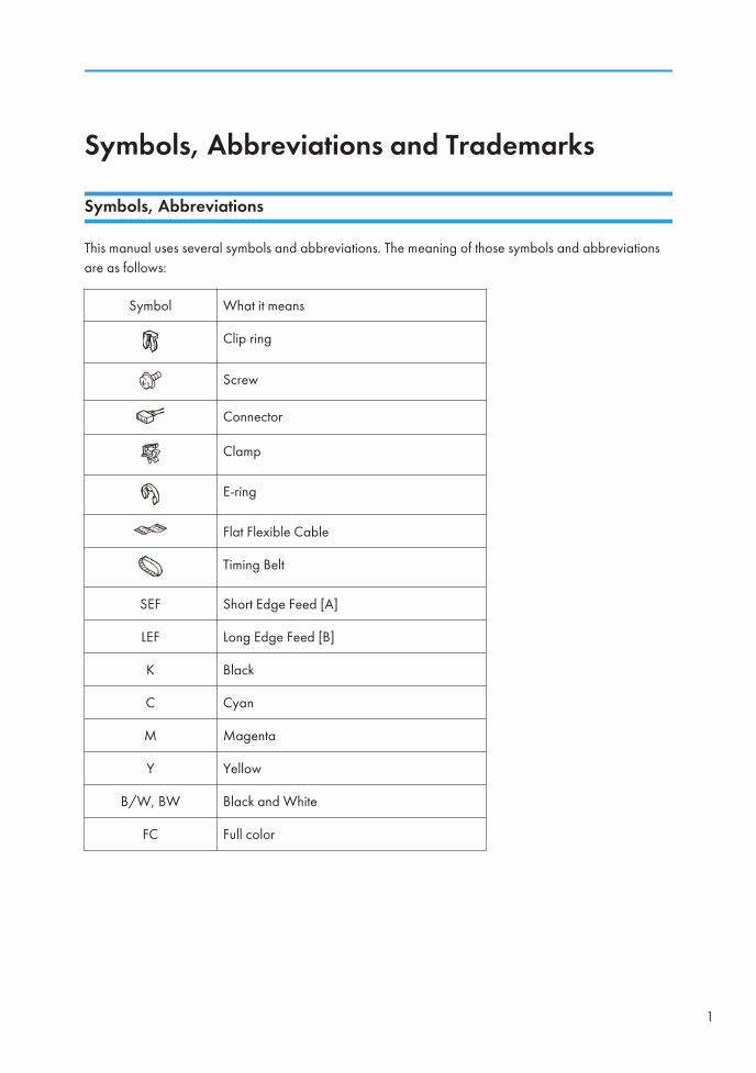
This manual uses several symbols and abbreviations. The meaning of those symbols and abbreviationsare as follows:
Symbol What it means
Clip ring
Screw
Connector
Clamp
E-ring
Flat Flexible Cable
Timing Belt
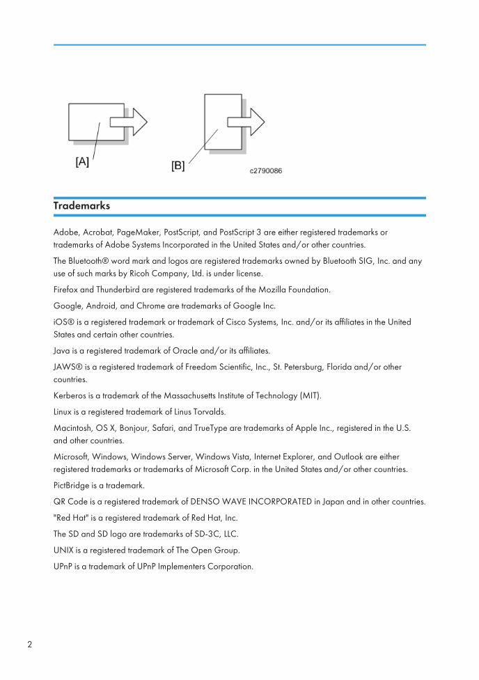
SEF Short Edge Feed [A]
LEF Long Edge Feed [B]
K Black
C Cyan
M Magenta
Y Yellow
B/W, BW Black and White
FC Full color
1
Trademarks
Adobe, Acrobat, PageMaker, PostScript, and PostScript 3 are either registered trademarks ortrademarks of Adobe Systems Incorporated in the United States and/or other countries.
The Bluetooth® word mark and logos are registered trademarks owned by Bluetooth SIG, Inc. and anyuse of such marks by Ricoh Company, Ltd. is under license.
Firefox and Thunderbird are registered trademarks of the Mozilla Foundation.
Google, Android, and Chrome are trademarks of Google Inc.
iOS® is a registered trademark or trademark of Cisco Systems, Inc. and/or its affiliates in the UnitedStates and certain other countries.
Java is a registered trademark of Oracle and/or its affiliates.
JAWS® is a registered trademark of Freedom Scientific, Inc., St. Petersburg, Florida and/or othercountries.
Kerberos is a trademark of the Massachusetts Institute of Technology (MIT).
Linux is a registered trademark of Linus Torvalds.
Macintosh, OS X, Bonjour, Safari, and TrueType are trademarks of Apple Inc., registered in the U.S.and other countries.
Microsoft, Windows, Windows Server, Windows Vista, Internet Explorer, and Outlook are eitherregistered trademarks or trademarks of Microsoft Corp. in the United States and/or other countries.
PictBridge is a trademark.
QR Code is a registered trademark of DENSO WAVE INCORPORATED in Japan and in other countries.
"Red Hat" is a registered trademark of Red Hat, Inc.
The SD and SD logo are trademarks of SD-3C, LLC.
UNIX is a registered trademark of The Open Group.
UPnP is a trademark of UPnP Implementers Corporation.
2
This product includes RSA BSAFE® Cryptographic software of EMC Corporation. RSA and BSAFE areregistered trademarks or trademarks of EMC Corporation in the United States and other countries.
The proper names of Internet Explorer 6, 7, and 8 are as follows:
• Microsoft® Internet Explorer® 6
• Windows® Internet Explorer® 7
• Windows® Internet Explorer® 8
The proper names of the Windows operating systems are as follows:
• The product names of Windows Vista are as follows:
Microsoft® Windows Vista® Ultimate
Microsoft® Windows Vista® Business
Microsoft® Windows Vista® Home Premium
Microsoft® Windows Vista® Home Basic
Microsoft® Windows Vista® Enterprise
• The product names of Windows 7 are as follows:
Microsoft® Windows® 7 Home Premium
Microsoft® Windows® 7 Professional
Microsoft® Windows® 7 Ultimate
Microsoft® Windows® 7 Enterprise
• The product names of Windows 8 are as follows:
Microsoft® Windows® 8
Microsoft® Windows® 8 Pro
Microsoft® Windows® 8 Enterprise
• The product names of Windows 8.1 are as follows:
Microsoft® Windows® 8.1
Microsoft® Windows® 8.1 Pro
Microsoft® Windows® 8.1 Enterprise
• The product names of Windows 10 are as follows:
3

Microsoft® Windows® 10 Home Premium
Microsoft® Windows® 10 Pro
Microsoft® Windows® 10 Enterprise
Microsoft® Windows® 10 Education
• The product names of Windows Server 2003 are as follows:
Microsoft® Windows Server® 2003 Standard Edition
Microsoft® Windows Server® 2003 Enterprise Edition
• The product names of Windows Server 2003 R2 are as follows:
Microsoft® Windows Server® 2003 R2 Standard Edition
Microsoft® Windows Server® 2003 R2 Enterprise Edition
• The product names of Windows Server 2008 are as follows:
Microsoft® Windows Server® 2008 Standard
Microsoft® Windows Server® 2008 Enterprise
• The product names of Windows Server 2008 R2 are as follows:
Microsoft® Windows Server® 2008 R2 Standard
Microsoft® Windows Server® 2008 R2 Enterprise
• The product names of Windows Server 2012 are as follows:
Microsoft® Windows Server® 2012 Foundation
Microsoft® Windows Server® 2012 Essentials
Microsoft® Windows Server® 2012 Standard
• The product names of Windows Server 2012 R2 are as follows:
Microsoft® Windows Server® 2012 R2 Foundation
Microsoft® Windows Server® 2012 R2 Essentials
Microsoft® Windows Server® 2012 R2 Standard
Other product names used herein are for identification purposes only and might be trademarks of theirrespective companies. We disclaim any and all rights to those marks.
Microsoft product screen shots reprinted with permission from Microsoft Corporation.
4
TABLE OF CONTENTSSymbols, Abbreviations and Trademarks.........................................................................................................1
Symbols, Abbreviations................................................................................................................................. 1
Trademarks..................................................................................................................................................... 2
1. Replacement and Adjustment
Exterior Covers....................................................................................................................................................7
ADF Front Cover.............................................................................................................................................7
ADF Rear Cover............................................................................................................................................. 8
Feed Cover..................................................................................................................................................... 9
Feed Unit...........................................................................................................................................................11
Original Feed Unit....................................................................................................................................... 11
Sensors, Feeler, and Switches.........................................................................................................................12
Original Registration Sensor....................................................................................................................... 12
Original Exit Sensor.....................................................................................................................................14
Separation Sensor, Skew Correction Sensor............................................................................................ 16
Original Width Sensor, Interval Sensor..................................................................................................... 17
Original Length Sensors.............................................................................................................................. 19
A4 LEF, LT LEF Sensor......................................................................................................................... 19
APS Feeler.................................................................................................................................................... 20
ADF Lift Interlock Switch, Lift Sensor...........................................................................................................21
Original Set Sensor......................................................................................................................................22
Bottom Plate HP Sensor............................................................................................................................... 23
Bottom Plate Position Sensor....................................................................................................................... 24
ADF Feed Cover Interlock Switch, Pick-up Roller HP Sensor...................................................................24
Motors...............................................................................................................................................................27
ADF Entrance Motor....................................................................................................................................27
ADF Scanning Motor...................................................................................................................................28
ADF Exit Motor.............................................................................................................................................29
ADF Bottom Plate Lift Motor........................................................................................................................ 31
ADF Pick-up Roller Lift Motor, ADF Transport Motor................................................................................32
ADF Feed Motor.......................................................................................................................................... 34
Rollers and Belts............................................................................................................................................... 36
Pick-up Roller, Transport Belt...................................................................................................................... 36
ADF Separation Roller.................................................................................................................................38
5
Boards...............................................................................................................................................................40
ADF Controller Board..................................................................................................................................40
CIS Unit............................................................................................................................................................. 41
CIS Unit.........................................................................................................................................................41
Reinstallation........................................................................................................................................43
CIS White Roller Cleaning..........................................................................................................................45
Adjustment after ADF Replacement................................................................................................................ 47
Checking the vertical registration............................................................................................................... 47
Checking the horizontal registration.......................................................................................................... 47
Checking skew............................................................................................................................................. 48
Checking magnification...............................................................................................................................48
Platen Adjustment.........................................................................................................................................49
2. Detailed Descriptions
SPDF DF3100 (D3B0).....................................................................................................................................51
Changes from the Previous Machine......................................................................................................... 51
Parts Layout.................................................................................................................................................. 55
Cross-Section of the ADF Unit............................................................................................................55
Scanning Sequence............................................................................................................................ 56
Mechanism...................................................................................................................................................57
Motors..................................................................................................................................................57
Original Pick-up.................................................................................................................................. 57
Bottom Plate Lift................................................................................................................................... 59
Original Feed and Separation Mechanism...................................................................................... 59
Skew Correction Mechanism............................................................................................................. 60
Original Size Detection...................................................................................................................... 61
Original Transport...............................................................................................................................63
Original Scanning...............................................................................................................................66
Jam Detection ..................................................................................................................................... 68
ADF SC Errors.............................................................................................................................................. 70
SP6-901-001 (Setting to give priority to stackability)..............................................................................72
6
1. Replacement and Adjustment
Exterior Covers
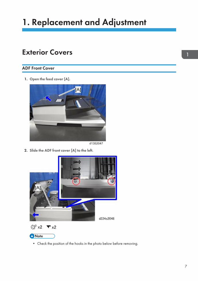
ADF Front Cover
1. Open the feed cover [A].
2. Slide the ADF front cover [A] to the left.
• Check the position of the hooks in the photo below before removing.
7
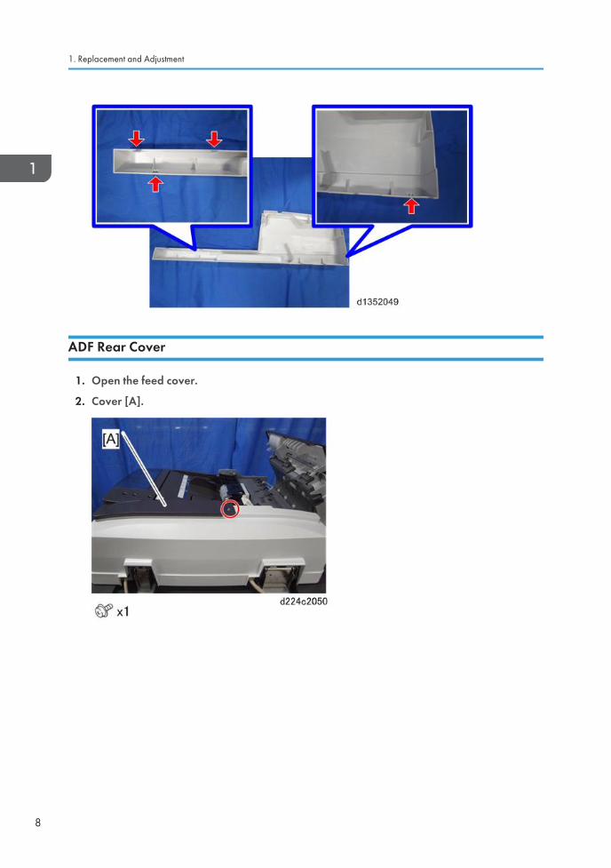
ADF Rear Cover
1. Open the feed cover.
2. Cover [A].
1. Replacement and Adjustment
8
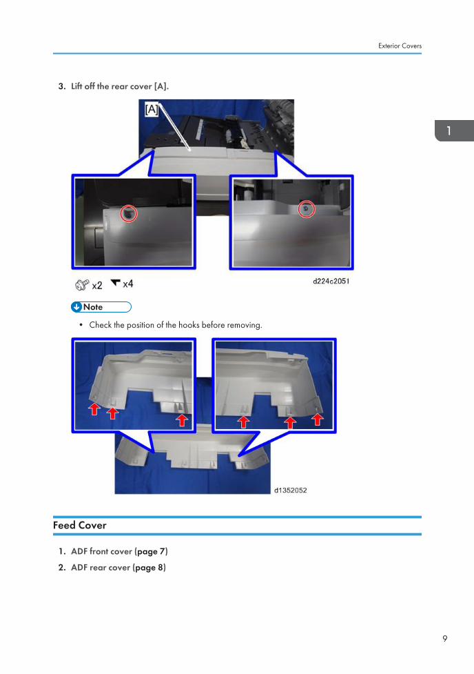
3. Lift off the rear cover [A].
• Check the position of the hooks before removing.
Feed Cover
1. ADF front cover (page 7)
2. ADF rear cover (page 8)
Exterior Covers
9
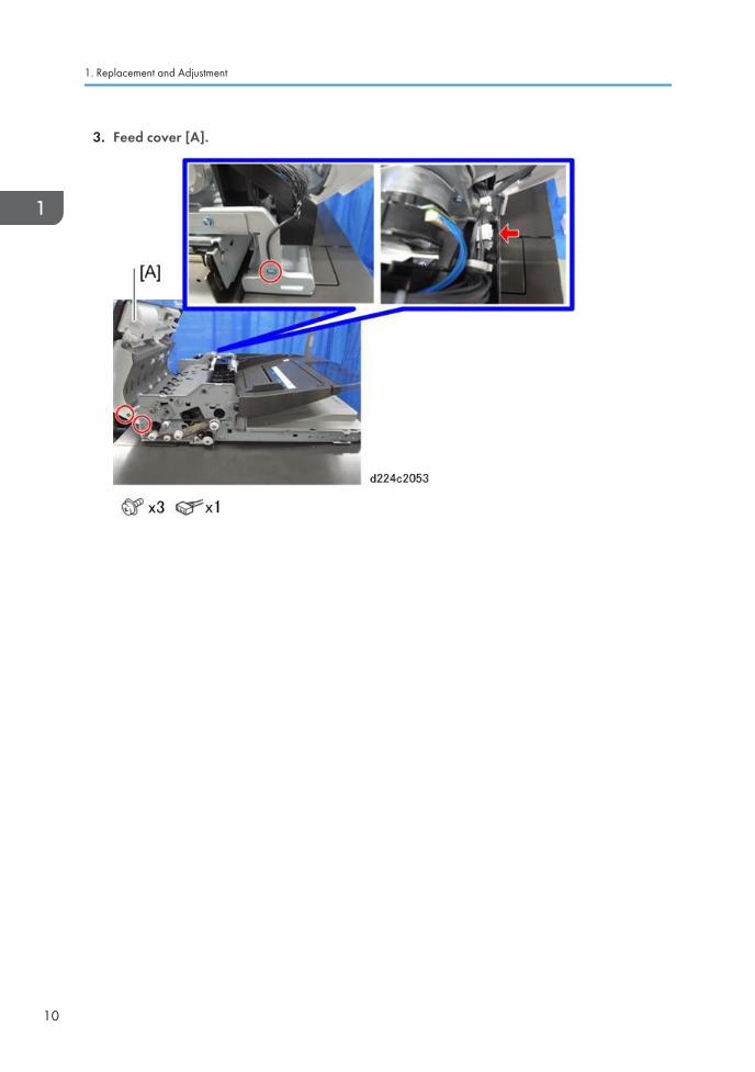
3. Feed cover [A].
1. Replacement and Adjustment
10
Feed Unit
Original Feed Unit
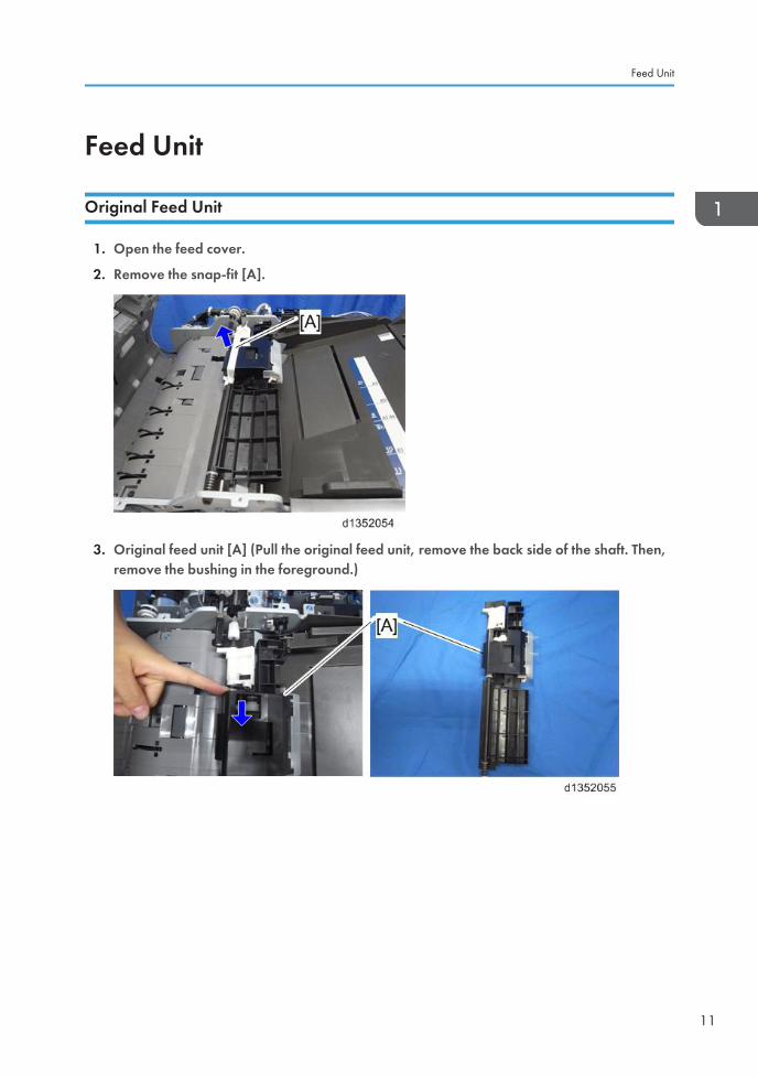
1. Open the feed cover.
2. Remove the snap-fit [A].
3. Original feed unit [A] (Pull the original feed unit, remove the back side of the shaft. Then,remove the bushing in the foreground.)
Feed Unit
11
Sensors, Feeler, and Switches
Original Registration Sensor
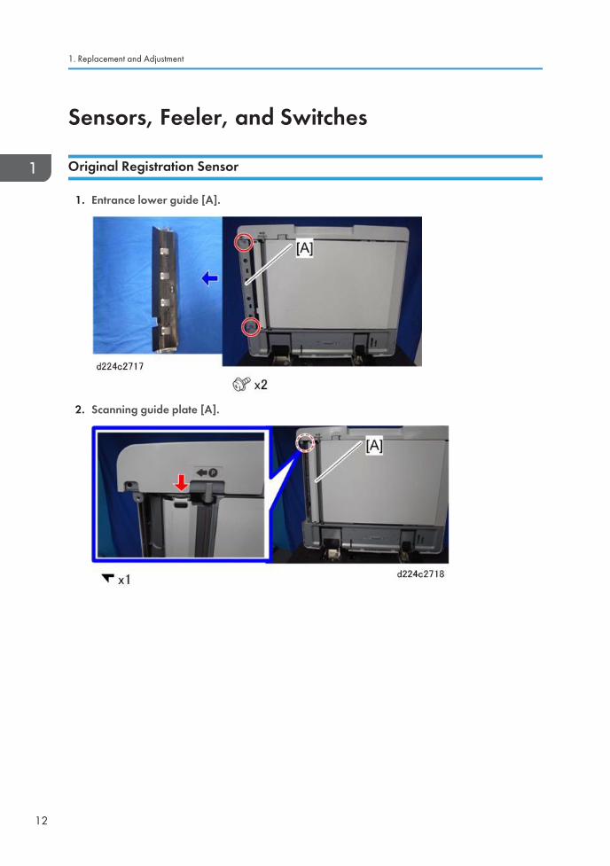
1. Entrance lower guide [A].
2. Scanning guide plate [A].
1. Replacement and Adjustment
12
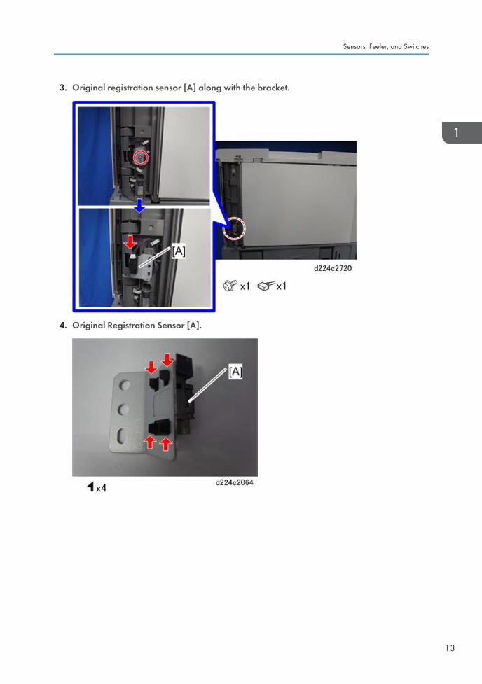
3. Original registration sensor [A] along with the bracket.
4. Original Registration Sensor [A].
Sensors, Feeler, and Switches
13
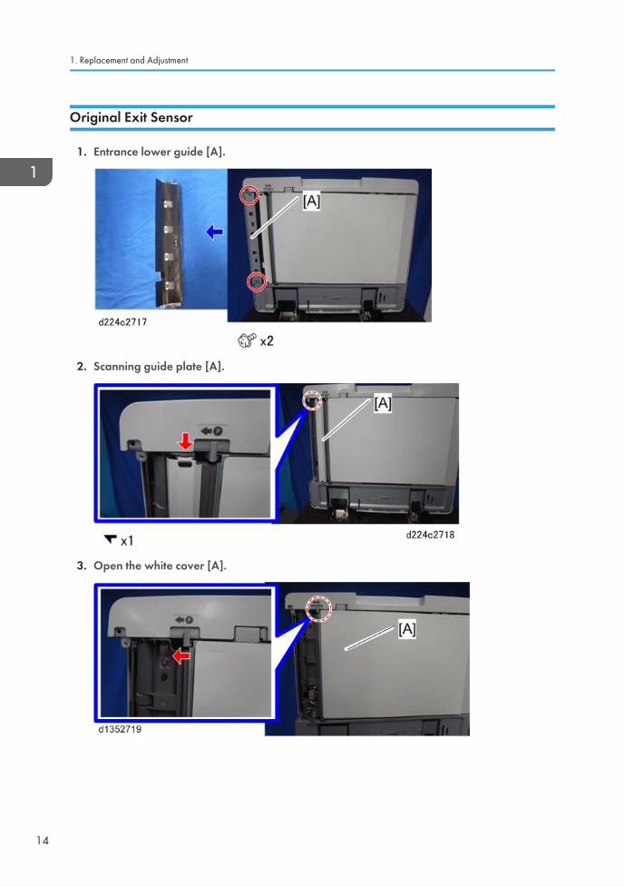
Original Exit Sensor
1. Entrance lower guide [A].
2. Scanning guide plate [A].
3. Open the white cover [A].
1. Replacement and Adjustment
14
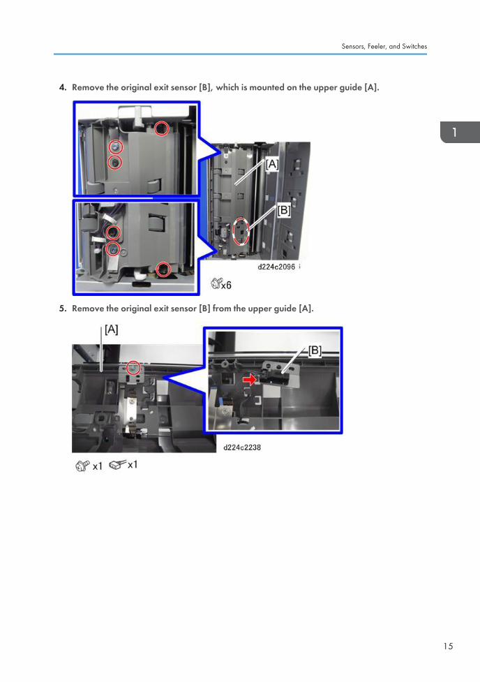
4. Remove the original exit sensor [B], which is mounted on the upper guide [A].
5. Remove the original exit sensor [B] from the upper guide [A].
Sensors, Feeler, and Switches
15
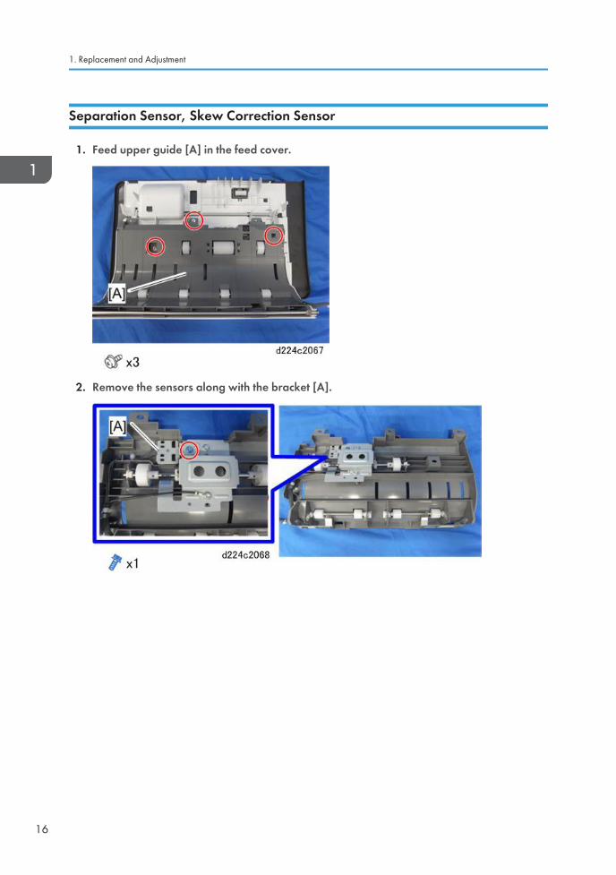
Separation Sensor, Skew Correction Sensor
1. Feed upper guide [A] in the feed cover.
2. Remove the sensors along with the bracket [A].
1. Replacement and Adjustment
16
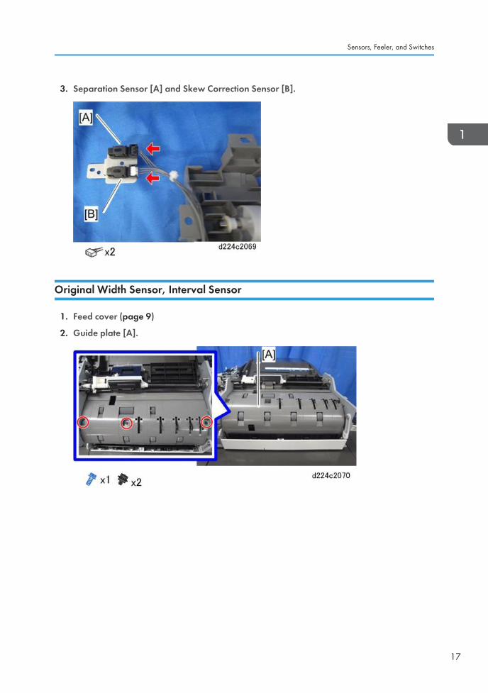
3. Separation Sensor [A] and Skew Correction Sensor [B].
Original Width Sensor, Interval Sensor
1. Feed cover (page 9)
2. Guide plate [A].
Sensors, Feeler, and Switches
17
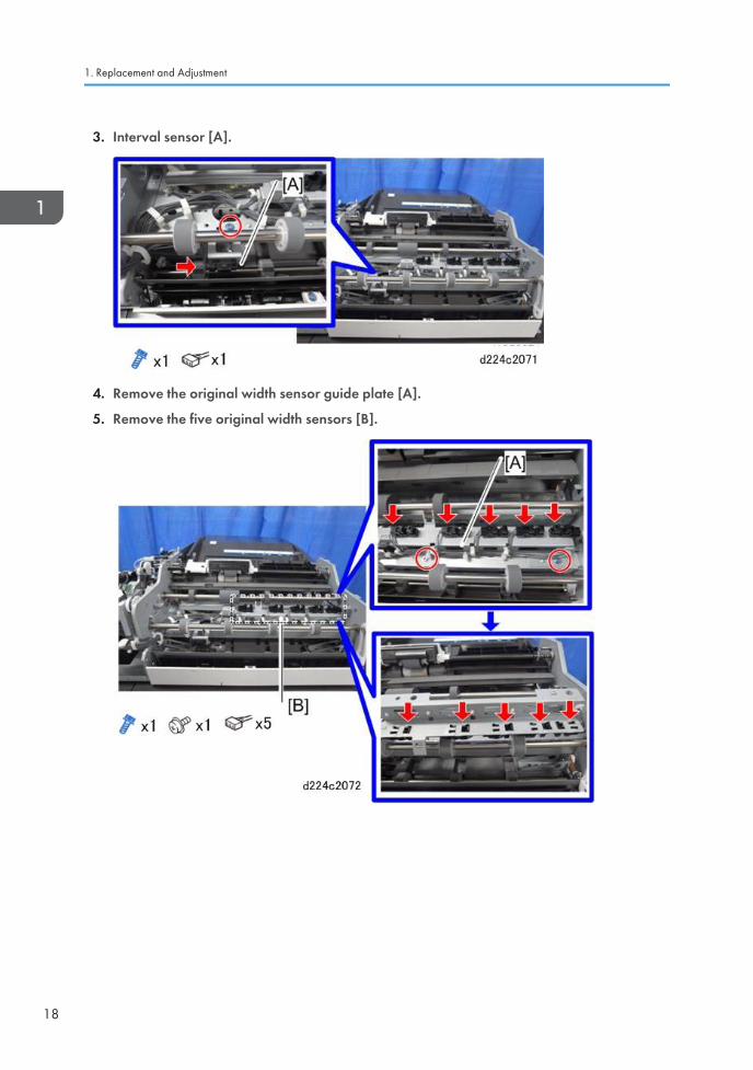
3. Interval sensor [A].
4. Remove the original width sensor guide plate [A].
5. Remove the five original width sensors [B].
1. Replacement and Adjustment
18
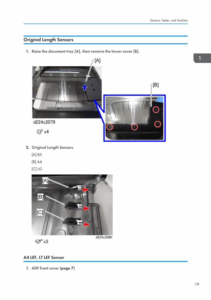
Original Length Sensors
1. Raise the document tray [A], then remove the lower cover [B].
2. Original Length Sensors
[A] B5
[B] A4
[C] LG
A4 LEF, LT LEF Sensor
1. ADF front cover (page 7)
Sensors, Feeler, and Switches
19
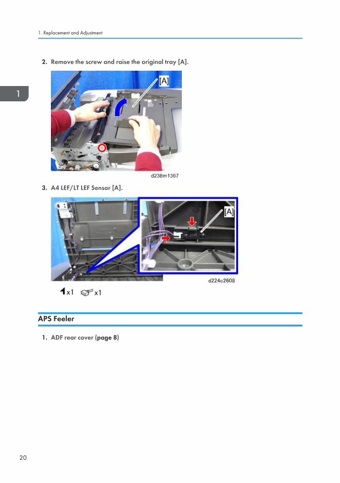
2. Remove the screw and raise the original tray [A].
3. A4 LEF/LT LEF Sensor [A].
APS Feeler
1. ADF rear cover (page 8)
1. Replacement and Adjustment
20
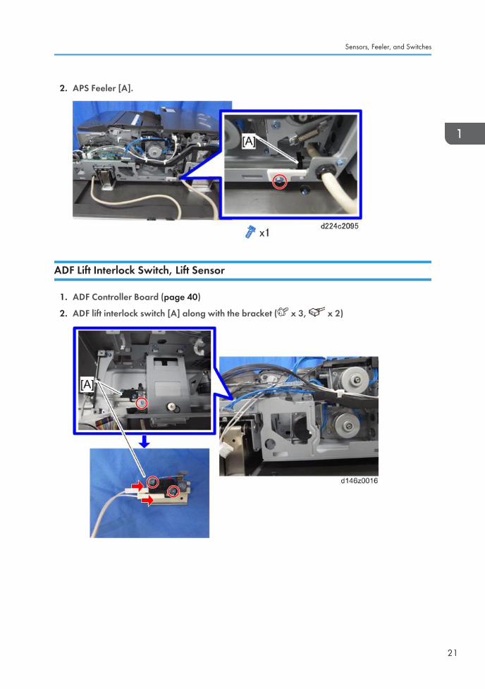
2. APS Feeler [A].
ADF Lift Interlock Switch, Lift Sensor
1. ADF Controller Board (page 40)
2. ADF lift interlock switch [A] along with the bracket ( x 3, x 2)
Sensors, Feeler, and Switches
21
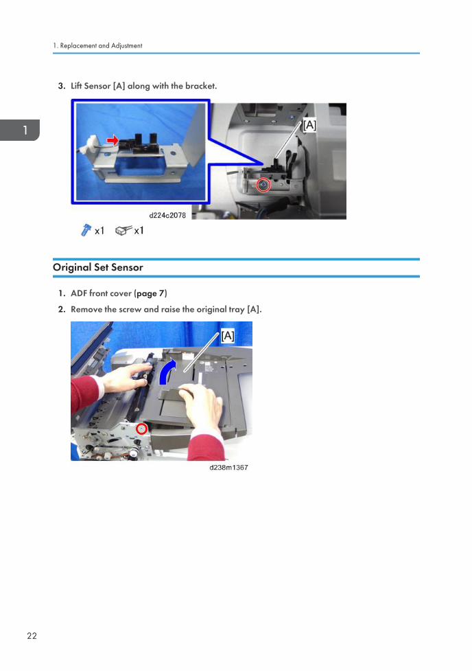
3. Lift Sensor [A] along with the bracket.
Original Set Sensor
1. ADF front cover (page 7)
2. Remove the screw and raise the original tray [A].
1. Replacement and Adjustment
22
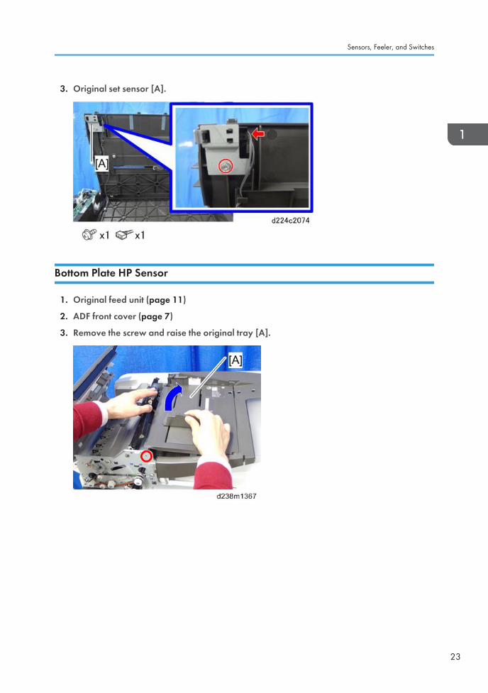
3. Original set sensor [A].
Bottom Plate HP Sensor
1. Original feed unit (page 11)
2. ADF front cover (page 7)
3. Remove the screw and raise the original tray [A].
Sensors, Feeler, and Switches
23
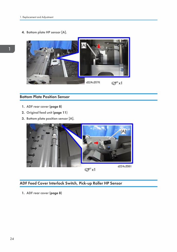
4. Bottom plate HP sensor [A].
Bottom Plate Position Sensor
1. ADF rear cover (page 8)
2. Original feed unit (page 11)
3. Bottom plate position sensor [A].
ADF Feed Cover Interlock Switch, Pick-up Roller HP Sensor
1. ADF rear cover (page 8)
1. Replacement and Adjustment
24
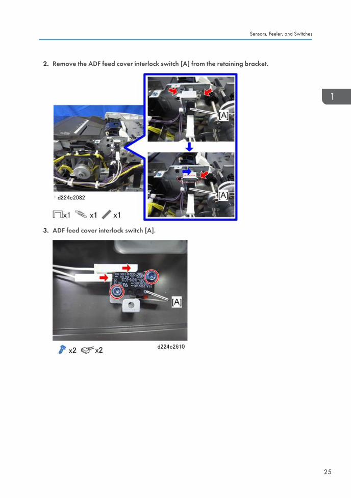
2. Remove the ADF feed cover interlock switch [A] from the retaining bracket.
3. ADF feed cover interlock switch [A].
Sensors, Feeler, and Switches
25
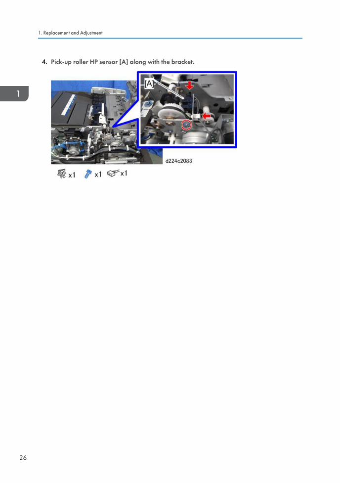
4. Pick-up roller HP sensor [A] along with the bracket.
1. Replacement and Adjustment
26
Motors
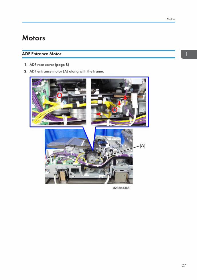
ADF Entrance Motor
1. ADF rear cover (page 8)
2. ADF entrance motor [A] along with the frame.
Motors
27
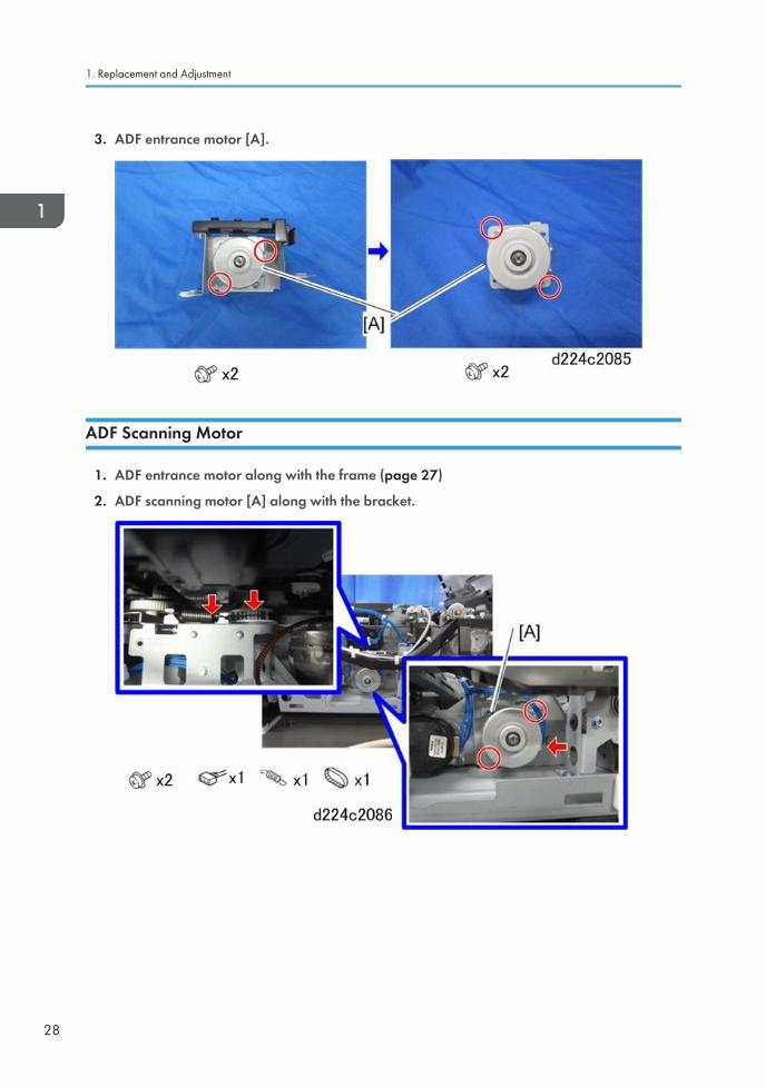
3. ADF entrance motor [A].
ADF Scanning Motor
1. ADF entrance motor along with the frame (page 27)
2. ADF scanning motor [A] along with the bracket.
1. Replacement and Adjustment
28
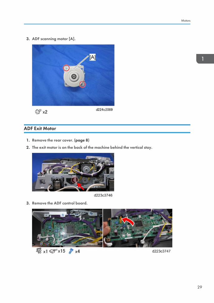
3. ADF scanning motor [A].
ADF Exit Motor
1. Remove the rear cover. (page 8)
2. The exit motor is on the back of the machine behind the vertical stay.
3. Remove the ADF control board.
Motors
29
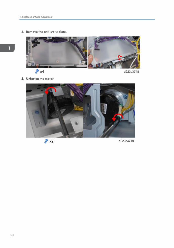
4. Remove the anti-static plate.
5. Unfasten the motor.
1. Replacement and Adjustment
30
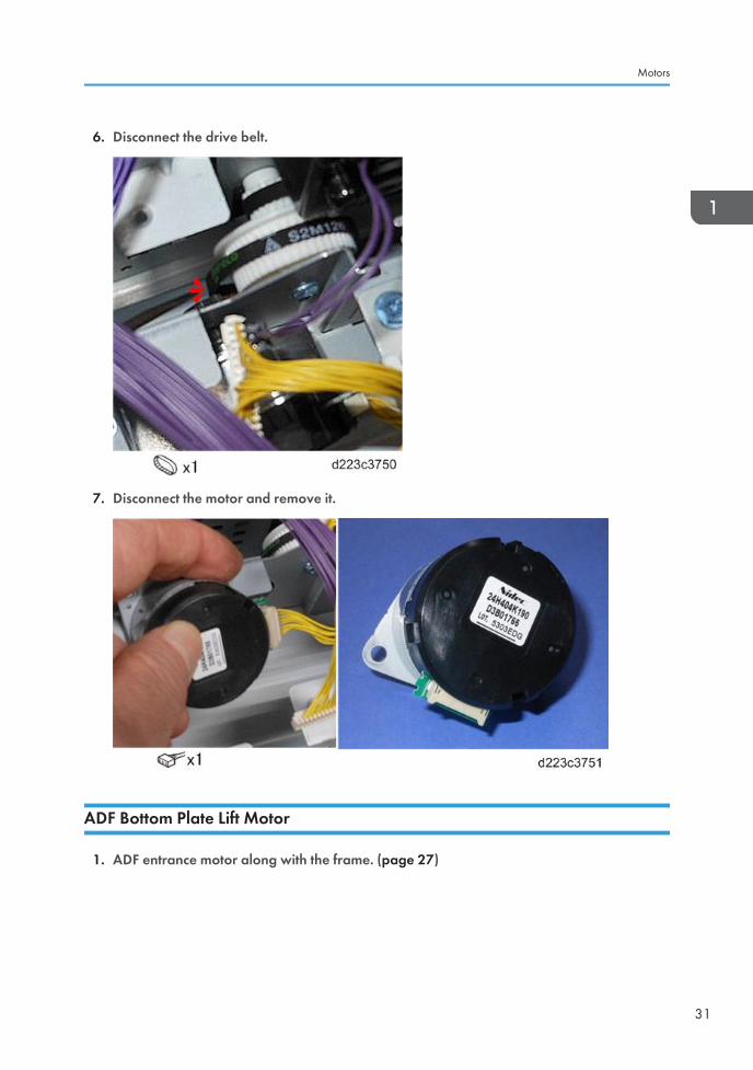
6. Disconnect the drive belt.
7. Disconnect the motor and remove it.
ADF Bottom Plate Lift Motor
1. ADF entrance motor along with the frame. (page 27)
Motors
31
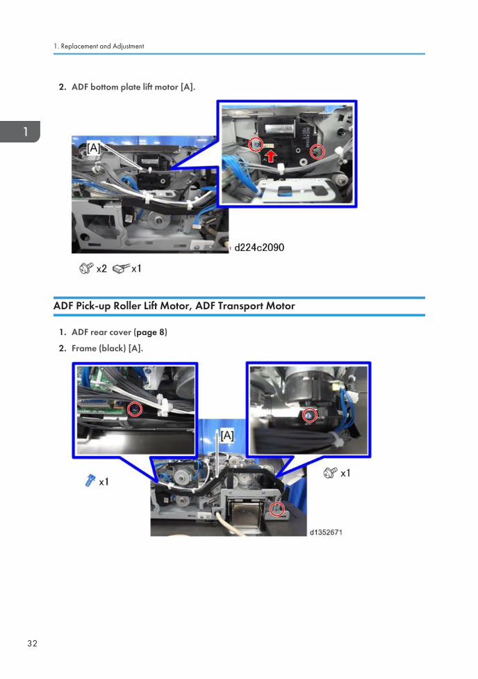
2. ADF bottom plate lift motor [A].
ADF Pick-up Roller Lift Motor, ADF Transport Motor
1. ADF rear cover (page 8)
2. Frame (black) [A].
1. Replacement and Adjustment
32
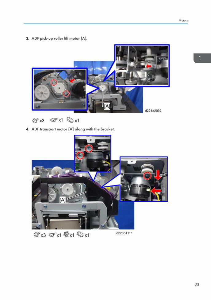
3. ADF pick-up roller lift motor [A].
4. ADF transport motor [A] along with the bracket.
Motors
33
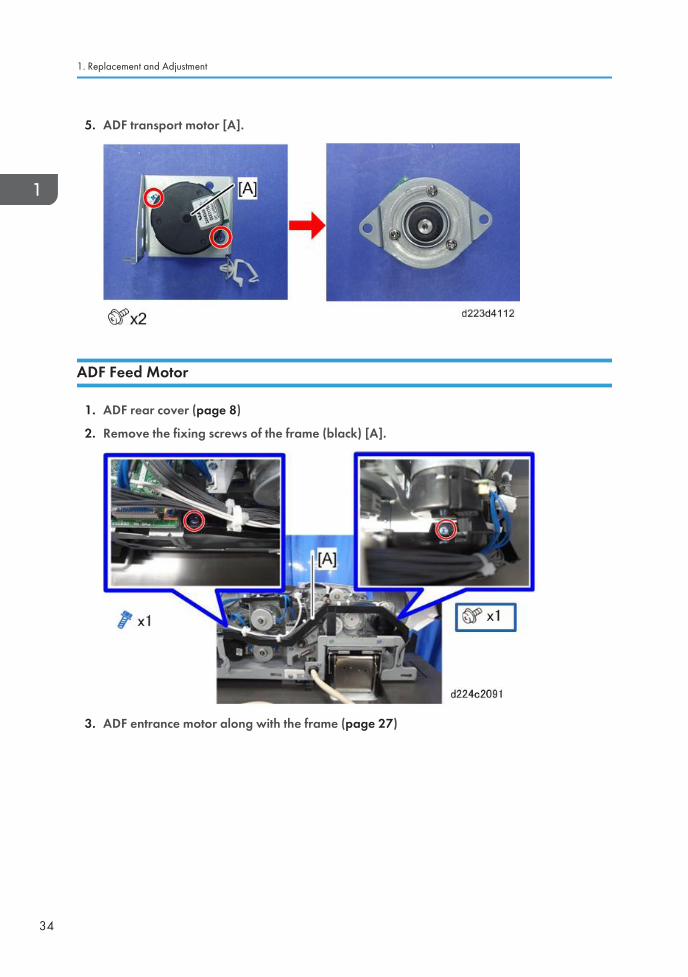
5. ADF transport motor [A].
ADF Feed Motor
1. ADF rear cover (page 8)
2. Remove the fixing screws of the frame (black) [A].
3. ADF entrance motor along with the frame (page 27)
1. Replacement and Adjustment
34
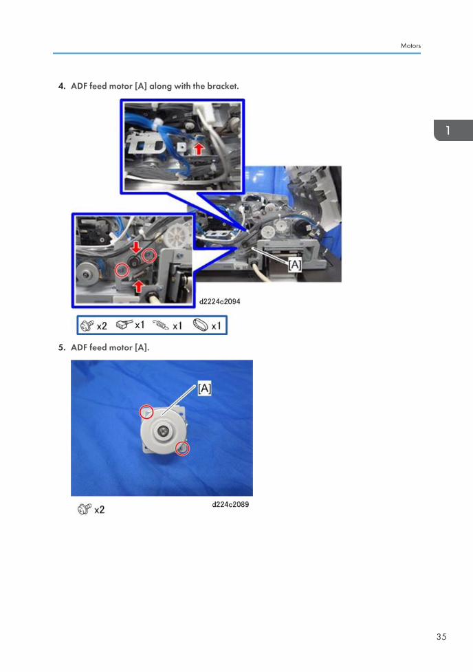
4. ADF feed motor [A] along with the bracket.
5. ADF feed motor [A].
Motors
35
Rollers and Belts
Pick-up Roller, Transport Belt
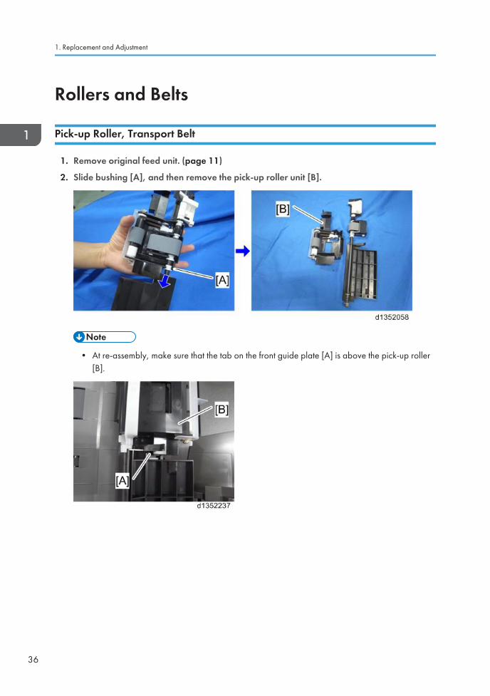
1. Remove original feed unit. (page 11)
2. Slide bushing [A], and then remove the pick-up roller unit [B].
• At re-assembly, make sure that the tab on the front guide plate [A] is above the pick-up roller[B].
1. Replacement and Adjustment
36
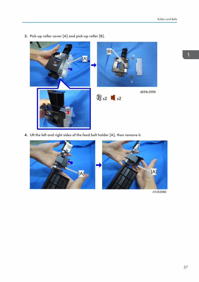
3. Pick-up roller cover [A] and pick-up roller [B].
4. Lift the left and right sides of the feed belt holder [A], then remove it.
Rollers and Belts
37

5. Remove the feed belt [B] from the feed belt holder [A].
ADF Separation Roller
1. Open the feed cover.
2. Original feed unit (page 11)
3. ADF separation roller cover [A].
1. Replacement and Adjustment
38
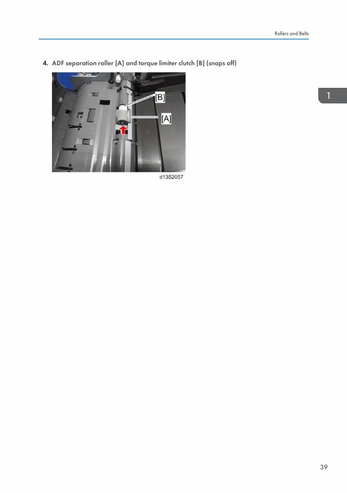
4. ADF separation roller [A] and torque limiter clutch [B] (snaps off)
Rollers and Belts
39
Boards
ADF Controller Board
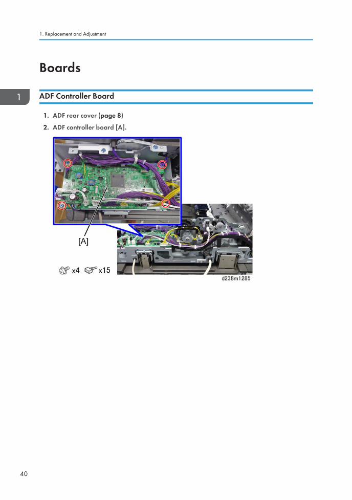
1. ADF rear cover (page 8)
2. ADF controller board [A].
1. Replacement and Adjustment
40
CIS Unit
CIS Unit
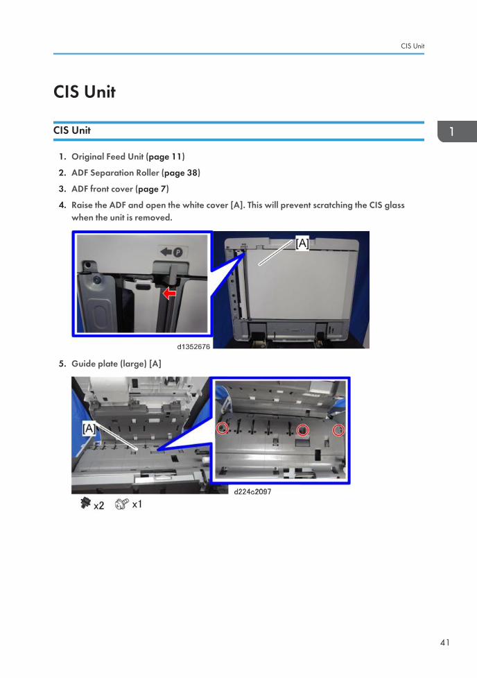
1. Original Feed Unit (page 11)
2. ADF Separation Roller (page 38)
3. ADF front cover (page 7)
4. Raise the ADF and open the white cover [A]. This will prevent scratching the CIS glasswhen the unit is removed.
5. Guide plate (large) [A]
CIS Unit
41
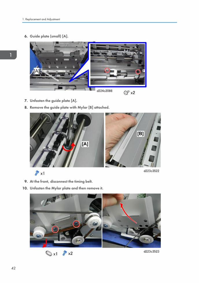
6. Guide plate (small) [A].
7. Unfasten the guide plate [A].
8. Remove the guide plate with Mylar [B] attached.
9. At the front, disconnect the timing belt.
10. Unfasten the Mylar plate and then remove it.
1. Replacement and Adjustment
42
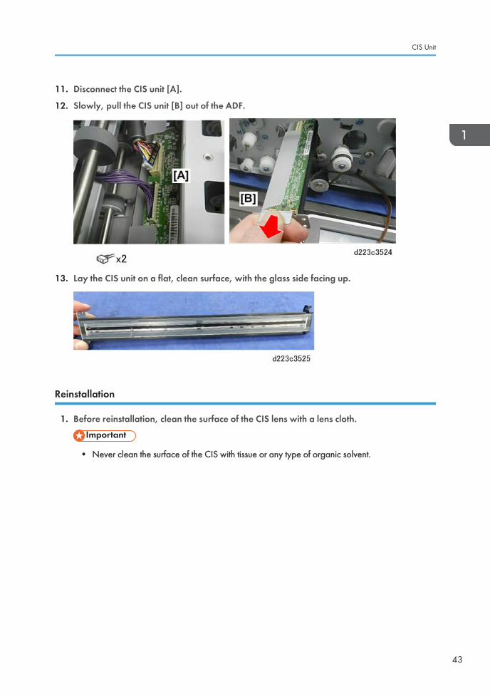
11. Disconnect the CIS unit [A].
12. Slowly, pull the CIS unit [B] out of the ADF.
13. Lay the CIS unit on a flat, clean surface, with the glass side facing up.
Reinstallation
1. Before reinstallation, clean the surface of the CIS lens with a lens cloth.
• Never clean the surface of the CIS with tissue or any type of organic solvent.
CIS Unit
43
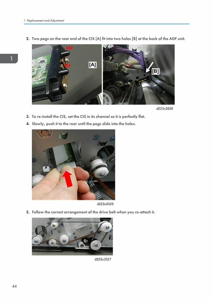
2. Two pegs on the rear end of the CIS [A] fit into two holes [B] at the back of the ADF unit.
3. To re-install the CIS, set the CIS in its channel so it is perfectly flat.
4. Slowly, push it to the rear until the pegs slide into the holes.
5. Follow the correct arrangement of the drive belt when you re-attach it.
1. Replacement and Adjustment
44
6. If you have replaced the CIS unit, do these SP three codes in the following order:
• SP4-730-001 (FROM ADF Factory Setting: CIS Parameter)
Writes the initial value of the scan parameter in FROM.
• SP4-730-004 (FROM Data Update)
Writes the SP value of the scan parameter in FROM.
• SP4-730-002 (FROM Main Factory Setting Execution ON/OFF)
Copies the parameters written in FROM to the engine board in the MFP.
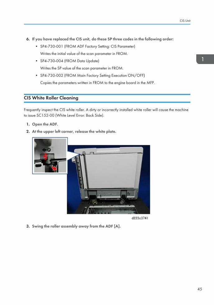
CIS White Roller Cleaning
Frequently inspect the CIS white roller. A dirty or incorrectly installed white roller will cause the machineto issue SC152-00 (White Level Error: Back Side).
1. Open the ADF.
2. At the upper left corner, release the white plate.
3. Swing the roller assembly away from the ADF [A].
CIS Unit
45
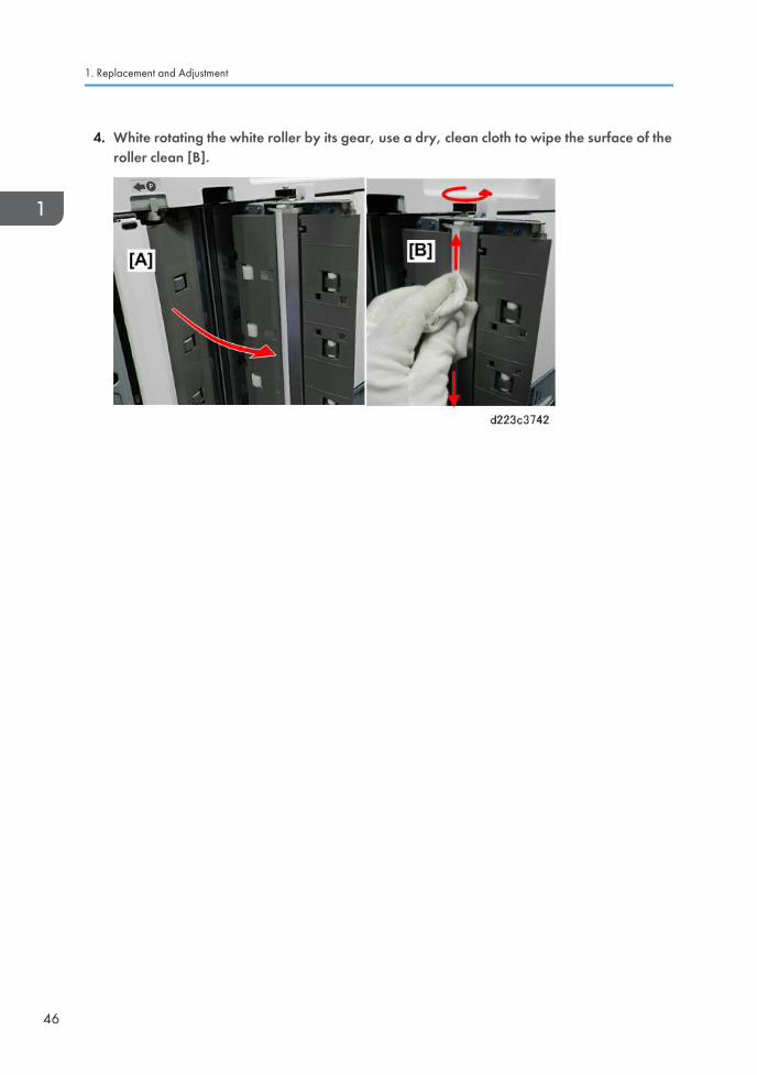
4. White rotating the white roller by its gear, use a dry, clean cloth to wipe the surface of theroller clean [B].
1. Replacement and Adjustment
46
Adjustment after ADF Replacement
• If the ADF is being replaced, do SP4-730-001, SP4-730-004 and SP4-730-002 (in that order)after the new ADF has been installed.
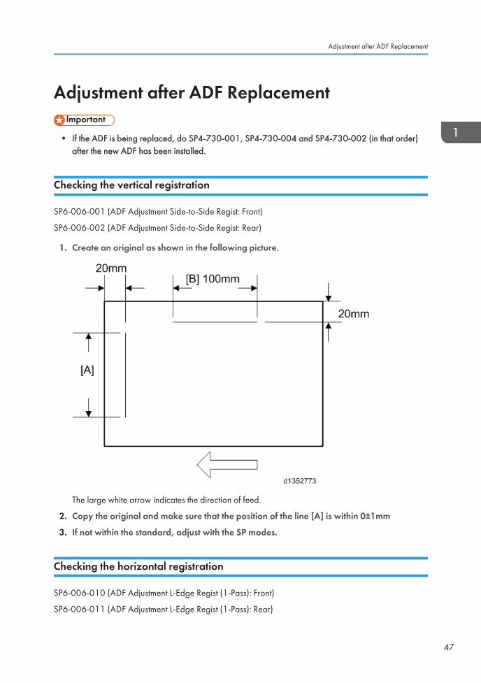
Checking the vertical registration
SP6-006-001 (ADF Adjustment Side-to-Side Regist: Front)
SP6-006-002 (ADF Adjustment Side-to-Side Regist: Rear)
1. Create an original as shown in the following picture.
The large white arrow indicates the direction of feed.
2. Copy the original and make sure that the position of the line [A] is within 0±1mm
3. If not within the standard, adjust with the SP modes.
Checking the horizontal registration
SP6-006-010 (ADF Adjustment L-Edge Regist (1-Pass): Front)
SP6-006-011 (ADF Adjustment L-Edge Regist (1-Pass): Rear)
Adjustment after ADF Replacement
47
1. Copy the original and make sure that the position of the line [B] is within 0±2mm.
2. If not within the standard, adjust with the SP modes.
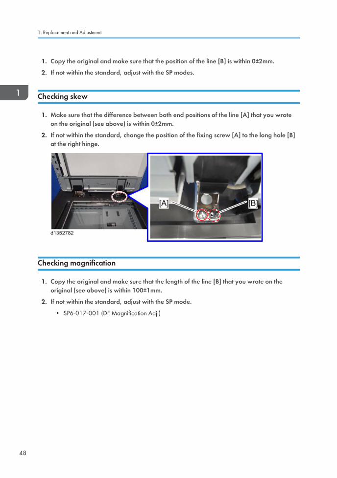
Checking skew
1. Make sure that the difference between both end positions of the line [A] that you wroteon the original (see above) is within 0±2mm.
2. If not within the standard, change the position of the fixing screw [A] to the long hole [B]at the right hinge.
Checking magnification
1. Copy the original and make sure that the length of the line [B] that you wrote on theoriginal (see above) is within 100±1mm.
2. If not within the standard, adjust with the SP mode.
• SP6-017-001 (DF Magnification Adj.)
1. Replacement and Adjustment
48
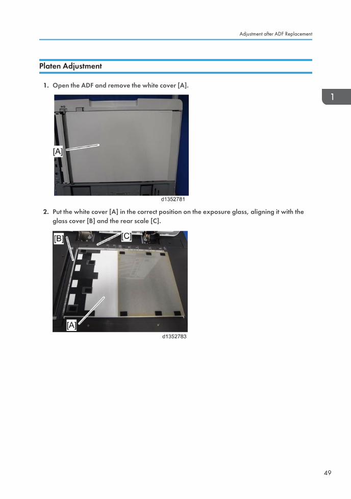
Platen Adjustment
1. Open the ADF and remove the white cover [A].
2. Put the white cover [A] in the correct position on the exposure glass, aligning it with theglass cover [B] and the rear scale [C].
Adjustment after ADF Replacement
49
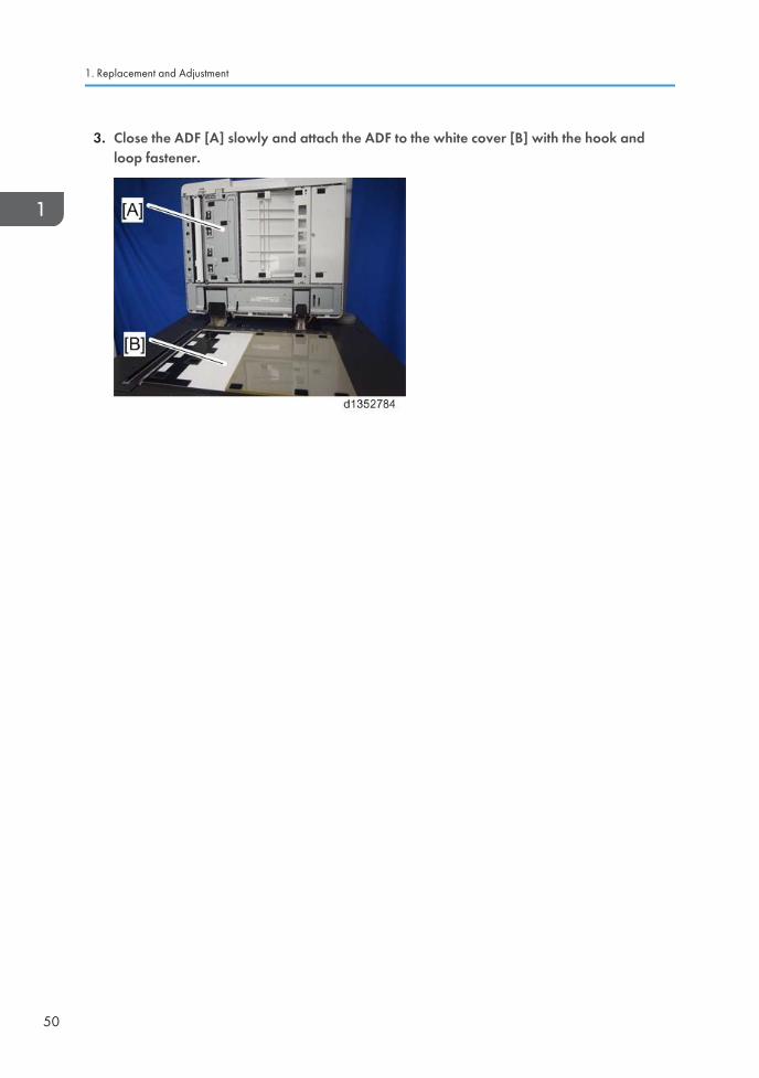
3. Close the ADF [A] slowly and attach the ADF to the white cover [B] with the hook andloop fastener.
1. Replacement and Adjustment
50
2. Detailed Descriptions
SPDF DF3100 (D3B0)
Changes from the Previous Machine
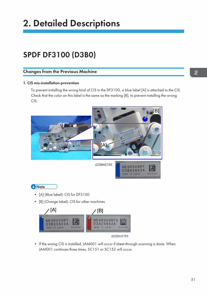
1. CIS mis-installation prevention
To prevent installing the wrong kind of CIS in the DF3100, a blue label [A] is attached to the CIS.Check that the color on this label is the same as the marking [B], to prevent installing the wrongCIS.
• [A] (Blue label): CIS for DF3100
• [B] (Orange label): CIS for other machines
• If the wrong CIS is installed, JAM001 will occur if sheet-through scanning is done. WhenJAM001 continues three times, SC151 or SC152 will occur.
51
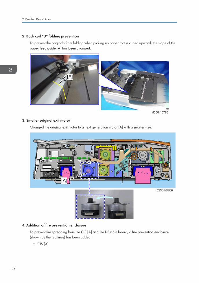
2. Back curl "U" folding prevention
To prevent the originals from folding when picking up paper that is curled upward, the slope of thepaper feed guide [A] has been changed.
3. Smaller original exit motor
Changed the original exit motor to a next generation motor [A] with a smaller size.
4. Addition of fire prevention enclosure
To prevent fire spreading from the CIS [A] and the DF main board, a fire prevention enclosure(shown by the red lines) has been added.
• CIS [A]
2. Detailed Descriptions
52
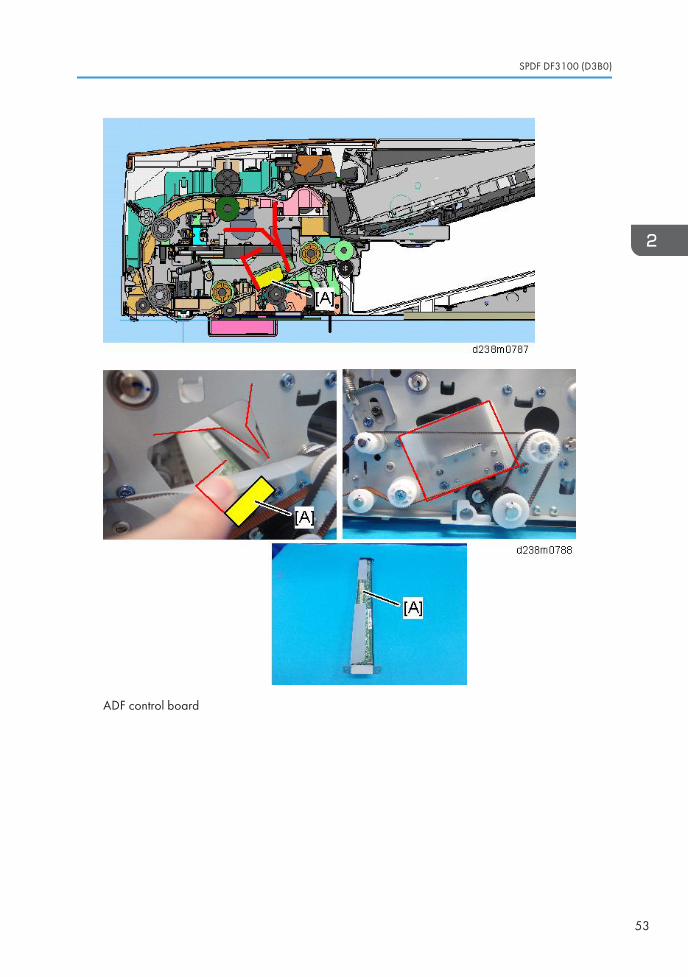
ADF control board
SPDF DF3100 (D3B0)
53
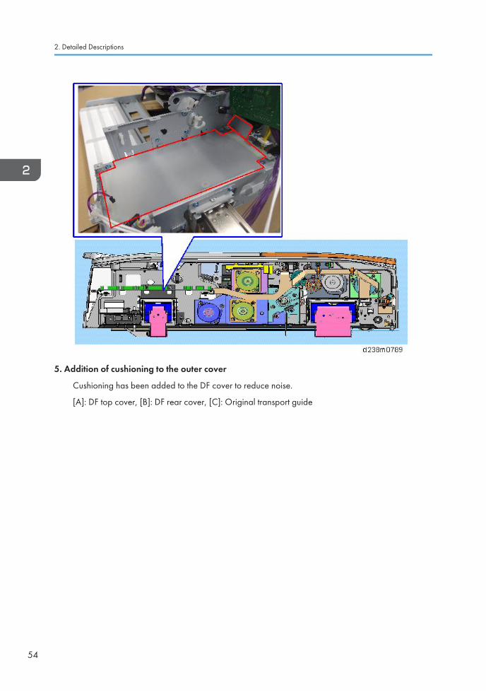
5. Addition of cushioning to the outer cover
Cushioning has been added to the DF cover to reduce noise.
[A]: DF top cover, [B]: DF rear cover, [C]: Original transport guide
2. Detailed Descriptions
54
.
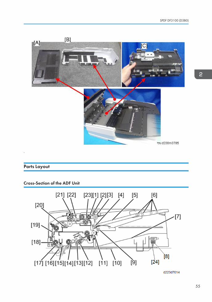
Parts Layout
Cross-Section of the ADF Unit
SPDF DF3100 (D3B0)
55
No, Part No. Part
1 Feed Belt 13 CIS
2 Bottom Plate Position Sensor 14 Original Exit Sensor
3 Pick-up Roller 15 Scanning guide plate
4 Original Set Sensor 16 Sheet-through exposure glass
5 Original Tray 17 Original Registration Sensor
6 Original Length Sensors 18 Scanning Entrance Roller
7 Output Tray 19 Interval Sensor
8 Lift Sensor 20 Original Width Sensors
9 Bottom Plate HP Sensor 21 Skew Correction Sensor
10 Exposure Glass 22 Separation Sensor
11 Exit Roller 23 ADF Separation Roller
12 CIS White Roller 24 ADF Lift Interlock Switch
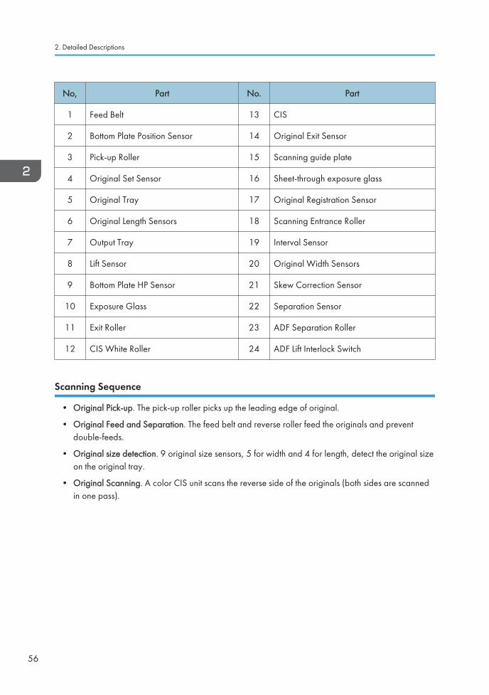
Scanning Sequence
• Original Pick-up. The pick-up roller picks up the leading edge of original.
• Original Feed and Separation. The feed belt and reverse roller feed the originals and preventdouble-feeds.
• Original size detection. 9 original size sensors, 5 for width and 4 for length, detect the original sizeon the original tray.
• Original Scanning. A color CIS unit scans the reverse side of the originals (both sides are scannedin one pass).
2. Detailed Descriptions
56
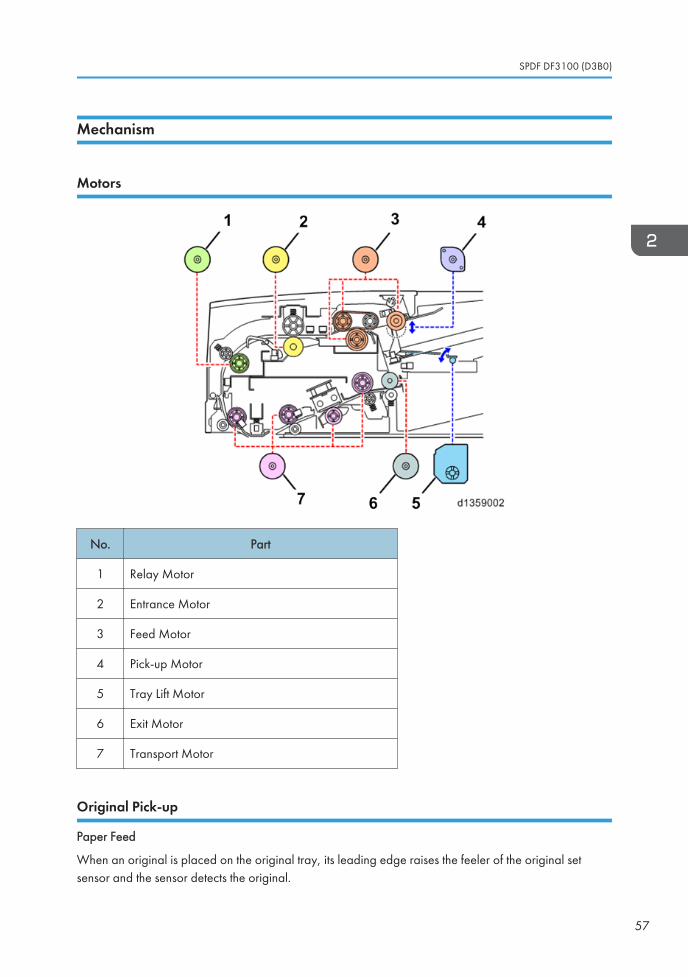
Mechanism
Motors
No. Part
1 Relay Motor
2 Entrance Motor
3 Feed Motor
4 Pick-up Motor
5 Tray Lift Motor
6 Exit Motor
7 Transport Motor
Original Pick-up
Paper Feed
When an original is placed on the original tray, its leading edge raises the feeler of the original setsensor and the sensor detects the original.
SPDF DF3100 (D3B0)
57
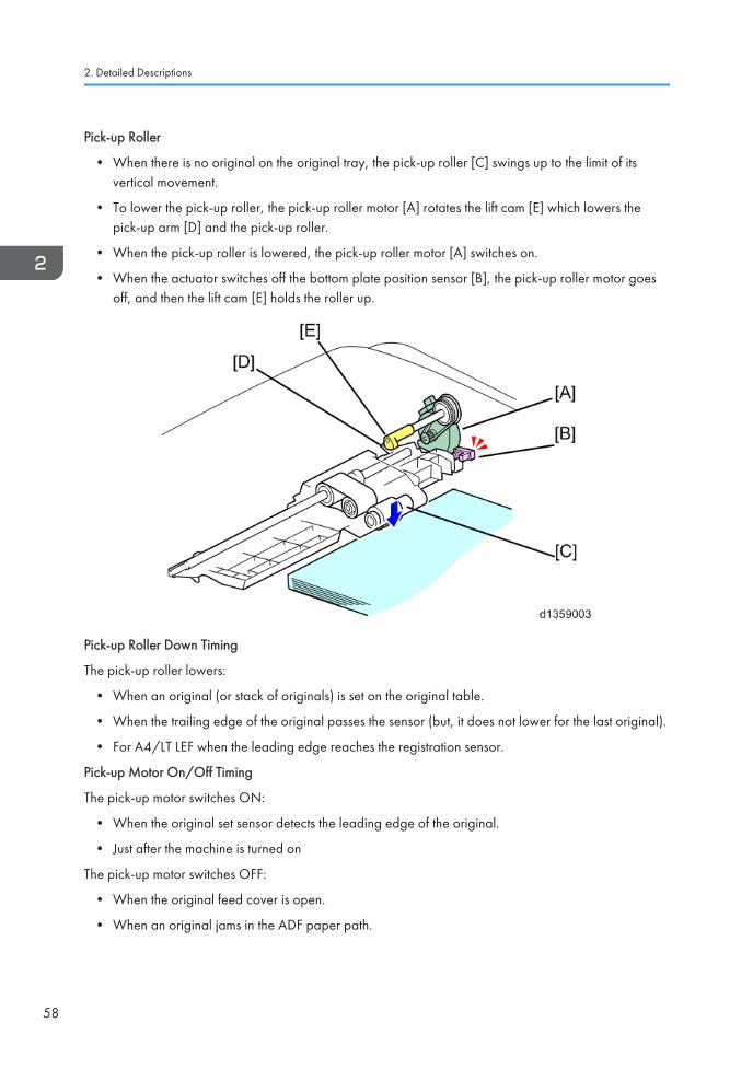
Pick-up Roller
• When there is no original on the original tray, the pick-up roller [C] swings up to the limit of itsvertical movement.
• To lower the pick-up roller, the pick-up roller motor [A] rotates the lift cam [E] which lowers thepick-up arm [D] and the pick-up roller.
• When the pick-up roller is lowered, the pick-up roller motor [A] switches on.
• When the actuator switches off the bottom plate position sensor [B], the pick-up roller motor goesoff, and then the lift cam [E] holds the roller up.
Pick-up Roller Down Timing
The pick-up roller lowers:
• When an original (or stack of originals) is set on the original table.
• When the trailing edge of the original passes the sensor (but, it does not lower for the last original).
• For A4/LT LEF when the leading edge reaches the registration sensor.
Pick-up Motor On/Off Timing
The pick-up motor switches ON:
• When the original set sensor detects the leading edge of the original.
• Just after the machine is turned on
The pick-up motor switches OFF:
• When the original feed cover is open.
• When an original jams in the ADF paper path.
2. Detailed Descriptions
58
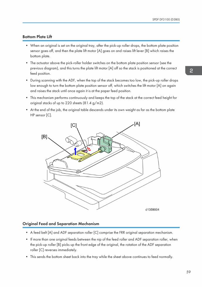
Bottom Plate Lift
• When an original is set on the original tray, after the pick-up roller drops, the bottom plate positionsensor goes off, and then the plate lift motor [A] goes on and raises lift lever [B] which raises thebottom plate.
• The actuator above the pick-roller holder switches on the bottom plate position sensor (see theprevious diagram), and this turns the plate lift motor [A] off so the stack is positioned at the correctfeed position.
• During scanning with the ADF, when the top of the stack becomes too low, the pick-up roller dropslow enough to turn the bottom plate position sensor off, which switches the lift motor [A] on againand raises the stack until once again it is at the paper feed position.
• This mechanism performs continuously and keeps the top of the stack at the correct feed height fororiginal stacks of up to 220 sheets (81.4 g/m2).
• At the end of the job, the original table descends under its own weight as far as the bottom plateHP sensor [C].
Original Feed and Separation Mechanism
• A feed belt [A] and ADF separation roller [C] comprise the FRR original separation mechanism.
• If more than one original feeds between the nip of the feed roller and ADF separation roller, whenthe pick-up roller [B] picks up the front edge of the original, the rotation of the ADF separationroller [C] reverses immediately.
• This sends the bottom sheet back into the tray while the sheet above continues to feed normally.
SPDF DF3100 (D3B0)
59
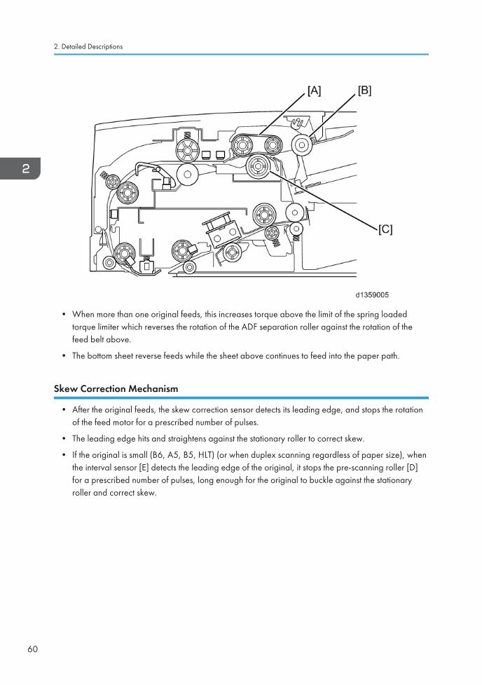
• When more than one original feeds, this increases torque above the limit of the spring loadedtorque limiter which reverses the rotation of the ADF separation roller against the rotation of thefeed belt above.
• The bottom sheet reverse feeds while the sheet above continues to feed into the paper path.
Skew Correction Mechanism
• After the original feeds, the skew correction sensor detects its leading edge, and stops the rotationof the feed motor for a prescribed number of pulses.
• The leading edge hits and straightens against the stationary roller to correct skew.
• If the original is small (B6, A5, B5, HLT) (or when duplex scanning regardless of paper size), whenthe interval sensor [E] detects the leading edge of the original, it stops the pre-scanning roller [D]for a prescribed number of pulses, long enough for the original to buckle against the stationaryroller and correct skew.
2. Detailed Descriptions
60
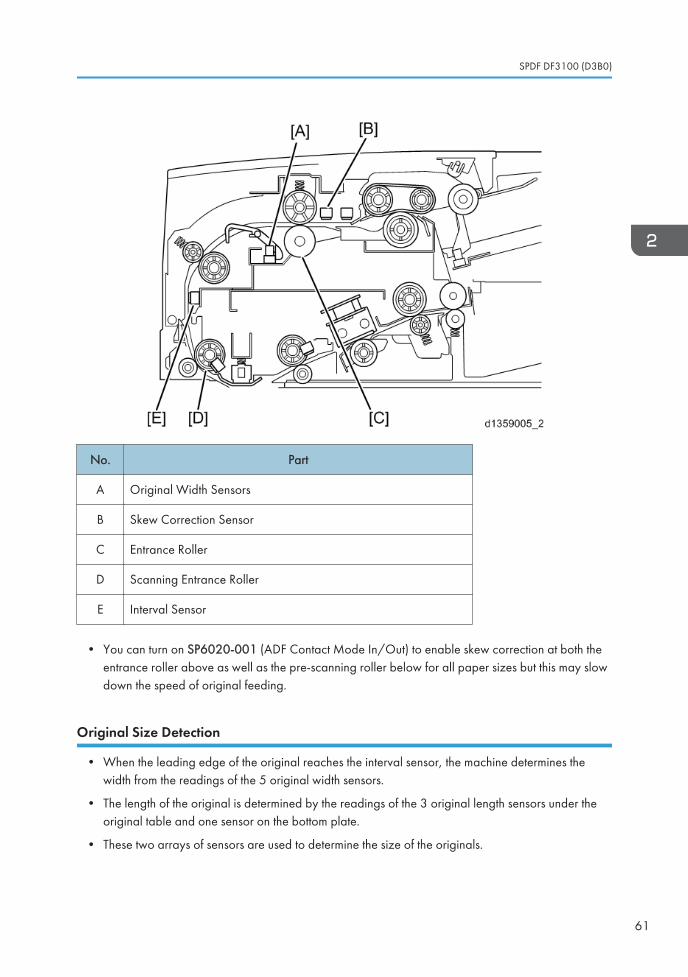
No. Part
A Original Width Sensors
B Skew Correction Sensor
C Entrance Roller
D Scanning Entrance Roller
E Interval Sensor
• You can turn on SP6020-001 (ADF Contact Mode In/Out) to enable skew correction at both theentrance roller above as well as the pre-scanning roller below for all paper sizes but this may slowdown the speed of original feeding.
Original Size Detection
• When the leading edge of the original reaches the interval sensor, the machine determines thewidth from the readings of the 5 original width sensors.
• The length of the original is determined by the readings of the 3 original length sensors under theoriginal table and one sensor on the bottom plate.
• These two arrays of sensors are used to determine the size of the originals.
SPDF DF3100 (D3B0)
61
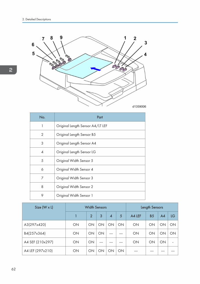
No. Part
1 Original Length Sensor A4/LT LEF
2 Original Length Sensor B5
3 Original Length Sensor A4
4 Original Length Sensor LG
5 Original Width Sensor 5
6 Original Width Sensor 4
7 Original Width Sensor 3
8 Original Width Sensor 2
9 Original Width Sensor 1
Size (W x L) Width Sensors Length Sensors
1 2 3 4 5 A4 LEF B5 A4 LG
A3(297x420) ON ON ON ON ON ON ON ON ON
B4(257x364) ON ON ON --- --- ON ON ON ON
A4 SEF (210x297) ON ON --- --- --- ON ON ON -
A4 LEF (297x210) ON ON ON ON ON --- --- --- ---
2. Detailed Descriptions
62
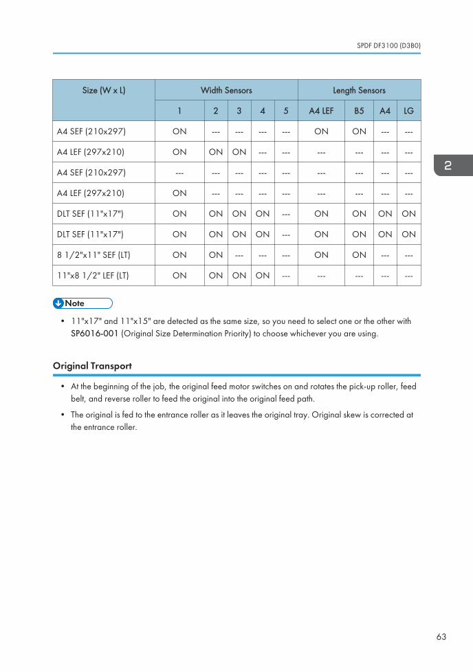
Size (W x L) Width Sensors Length Sensors
1 2 3 4 5 A4 LEF B5 A4 LG
A4 SEF (210x297) ON --- --- --- --- ON ON --- ---
A4 LEF (297x210) ON ON ON --- --- --- --- --- ---
A4 SEF (210x297) --- --- --- --- --- --- --- --- ---
A4 LEF (297x210) ON --- --- --- --- --- --- --- ---
DLT SEF (11"x17") ON ON ON ON --- ON ON ON ON
DLT SEF (11"x17") ON ON ON ON --- ON ON ON ON
8 1/2"x11" SEF (LT) ON ON --- --- --- ON ON --- ---
11"x8 1/2" LEF (LT) ON ON ON ON --- --- --- --- ---
• 11"x17" and 11"x15" are detected as the same size, so you need to select one or the other withSP6016-001 (Original Size Determination Priority) to choose whichever you are using.
Original Transport
• At the beginning of the job, the original feed motor switches on and rotates the pick-up roller, feedbelt, and reverse roller to feed the original into the original feed path.
• The original is fed to the entrance roller as it leaves the original tray. Original skew is corrected atthe entrance roller.
SPDF DF3100 (D3B0)
63
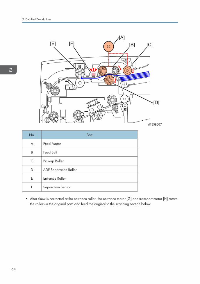
No. Part
A Feed Motor
B Feed Belt
C Pick-up Roller
D ADF Separation Roller
E Entrance Roller
F Separation Sensor
• After skew is corrected at the entrance roller, the entrance motor [G] and transport motor [H] rotatethe rollers in the original path and feed the original to the scanning section below.
2. Detailed Descriptions
64
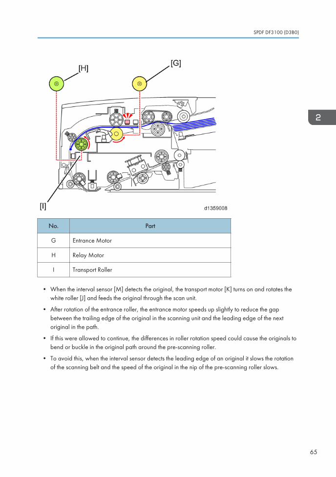
No. Part
G Entrance Motor
H Relay Motor
I Transport Roller
• When the interval sensor [M] detects the original, the transport motor [K] turns on and rotates thewhite roller [J] and feeds the original through the scan unit.
• After rotation of the entrance roller, the entrance motor speeds up slightly to reduce the gapbetween the trailing edge of the original in the scanning unit and the leading edge of the nextoriginal in the path.
• If this were allowed to continue, the differences in roller rotation speed could cause the originals tobend or buckle in the original path around the pre-scanning roller.
• To avoid this, when the interval sensor detects the leading edge of an original it slows the rotationof the scanning belt and the speed of the original in the nip of the pre-scanning roller slows.
SPDF DF3100 (D3B0)
65
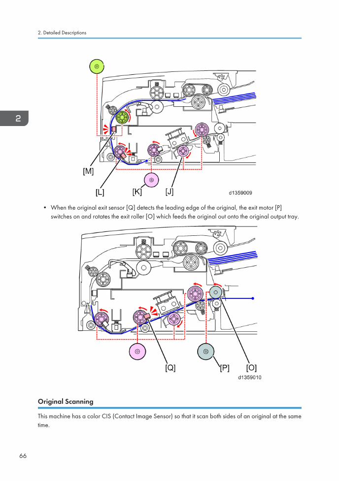
• When the original exit sensor [Q] detects the leading edge of the original, the exit motor [P]switches on and rotates the exit roller [O] which feeds the original out onto the original output tray.
Original Scanning
This machine has a color CIS (Contact Image Sensor) so that it scan both sides of an original at the sametime.
2. Detailed Descriptions
66
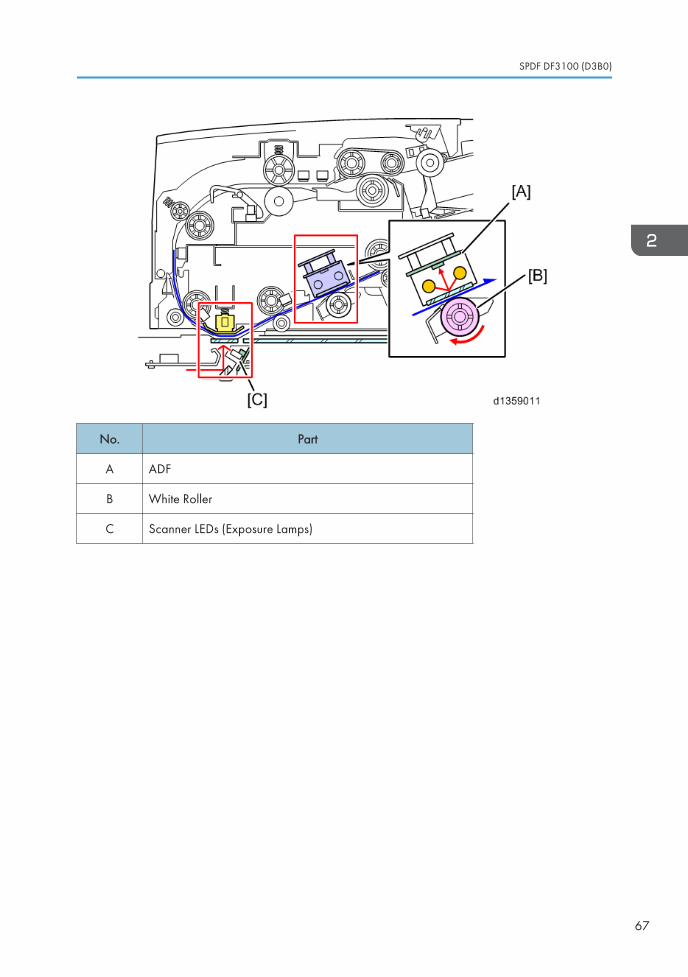
No. Part
A ADF
B White Roller
C Scanner LEDs (Exposure Lamps)
SPDF DF3100 (D3B0)
67
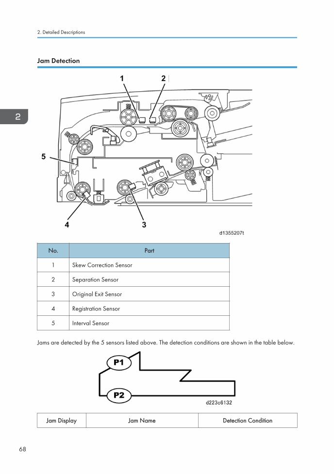
Jam Detection
No. Part
1 Skew Correction Sensor
2 Separation Sensor
3 Original Exit Sensor
4 Registration Sensor
5 Interval Sensor
Jams are detected by the 5 sensors listed above. The detection conditions are shown in the table below.
Jam Display Jam Name Detection Condition
2. Detailed Descriptions
68
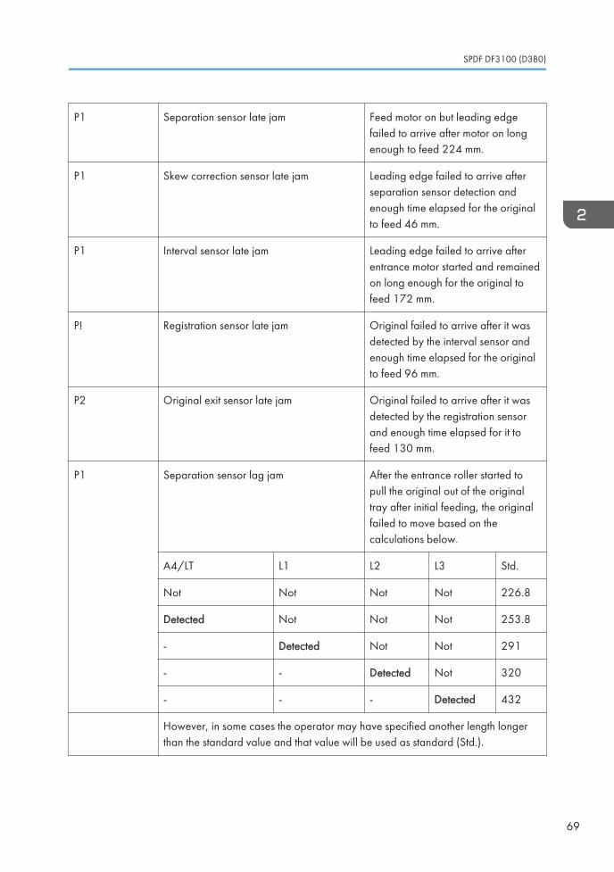
P1 Separation sensor late jam Feed motor on but leading edgefailed to arrive after motor on longenough to feed 224 mm.
P1 Skew correction sensor late jam Leading edge failed to arrive afterseparation sensor detection andenough time elapsed for the originalto feed 46 mm.
P1 Interval sensor late jam Leading edge failed to arrive afterentrance motor started and remainedon long enough for the original tofeed 172 mm.
P! Registration sensor late jam Original failed to arrive after it wasdetected by the interval sensor andenough time elapsed for the originalto feed 96 mm.
P2 Original exit sensor late jam Original failed to arrive after it wasdetected by the registration sensorand enough time elapsed for it tofeed 130 mm.
P1 Separation sensor lag jam After the entrance roller started topull the original out of the originaltray after initial feeding, the originalfailed to move based on thecalculations below.
A4/LT L1 L2 L3 Std.
Not Not Not Not 226.8
Detected Not Not Not 253.8
- Detected Not Not 291
- - Detected Not 320
- - - Detected 432
However, in some cases the operator may have specified another length longerthan the standard value and that value will be used as standard (Std.).
SPDF DF3100 (D3B0)
69
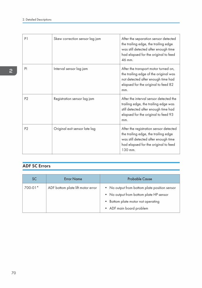
P1 Skew correction sensor lag jam After the separation sensor detectedthe trailing edge, the trailing edgewas still detected after enough timehad elapsed for the original to feed46 mm.
P! Interval sensor lag jam After the transport motor turned on,the trailing edge of the original wasnot detected after enough time hadelapsed for the original to feed 82mm.
P2 Registration sensor lag jam After the interval sensor detected thetrailing edge, the trailing edge wasstill detected after enough time hadelapsed for the original to feed 93mm.
P2 Original exit sensor late lag After the registration sensor detectedthe trailing edge, the trailing edgewas still detected after enough timehad elapsed for the original to feed130 mm.
ADF SC Errors
SC Error Name Probable Cause
700-01* ADF bottom plate lift motor error • No output from bottom plate position sensor
• No output from bottom plate HP sensor
• Bottom plate motor not operating
• ADF main board problem
2. Detailed Descriptions
70
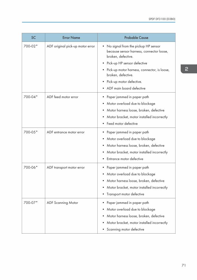
SC Error Name Probable Cause
700-02* ADF original pick-up motor error • No signal from the pickup HP sensorbecause sensor harness, connector loose,broken, defective.
• Pick-up HP sensor defective
• Pick-up motor harness, connector, is loose,broken, defective.
• Pick-up motor defective.
• ADF main board defective
700-04* ADF feed motor error • Paper jammed in paper path
• Motor overload due to blockage
• Motor harness loose, broken, defective
• Motor bracket, motor installed incorrectly
• Feed motor defective
700-05* ADF entrance motor error • Paper jammed in paper path
• Motor overload due to blockage
• Motor harness loose, broken, defective
• Motor bracket, motor installed incorrectly
• Entrance motor defective
700-06* ADF transport motor error • Paper jammed in paper path
• Motor overload due to blockage
• Motor harness loose, broken, defective
• Motor bracket, motor installed incorrectly
• Transport motor defective
700-07* ADF Scanning Motor • Paper jammed in paper path
• Motor overload due to blockage
• Motor harness loose, broken, defective
• Motor bracket, motor installed incorrectly
• Scanning motor defective
SPDF DF3100 (D3B0)
71
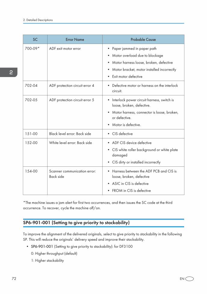
SC Error Name Probable Cause
700-09* ADF exit motor error • Paper jammed in paper path
• Motor overload due to blockage
• Motor harness loose, broken, defective
• Motor bracket, motor installed incorrectly
• Exit motor defective
702-04 ADF protection circuit error 4 • Defective motor or harness on the interlockcircuit.
702-05 ADF protection circuit error 5 • Interlock power circuit harness, switch isloose, broken, defective.
• Motor harness, connector is loose, broken,or defective.
• Motor is defective.
151-00 Black level error: Back side • CIS defective
152-00 White level error: Back side • ADF CIS device defective
• CIS white roller background or white platedamaged
• CIS dirty or installed incorrectly
154-00 Scanner communication error:Back side
• Harness between the ADF PCB and CIS isloose, broken, defective
• ASIC in CIS is defective
• FROM in CIS is defective
*The machine issues a jam alert for first two occurrences, and then issues the SC code at the thirdoccurrence. To recover, cycle the machine off/on.
SP6-901-001 (Setting to give priority to stackability)
To improve the alignment of the delivered originals, select to give priority to stackability in the followingSP. This will reduce the originals’ delivery speed and improve their stackability.
• SP6-901-001 (Setting to give priority to stackability): for DF3100
0: Higher throughput (default)
1: Higher stackability
2. Detailed Descriptions
72 EN