Embed Size (px)
Citation preview
Spatial variability of liquefaction susceptibility in the
Metropolitan area of Granada (Spain)
I. Valverde-Palacios & Valverde-Espinosa Department of Building Construction, Building Engineering School, University of Granada.
Campus de Fuentenueva s/n 18071, Granada (Spain)
F. Vidal Andalusian Institute of Geophysics. University of Granada. Campus Universitario de Cartuja
18071 Granada (Spain)
J. Chacón & C. Irigaray Department of Civil Engineering. University of Granada. Campus de Fuentenueva s/n 18071,
Granada (Spain)
SUMMARY:
Underlying the metropolitan area of Granada (southern Spain) exist thick Quaternary sediments with Holocene
deposits extending more than 200 m. In addition, there is a substantial shallow groundwater reservoir where the
water table is at a depth of only a few meters in its NW zone. This study assesses local liquefaction throughout
the area. We have estimated liquefaction susceptibility at 104 sites on the basis of (N1)60 values, fines content,
water table depth, and the magnitude of the reference earthquake. Input data, parameters, and results were
incorporated into a GIS and presented in maps and tables. When seismological data (e.g. Vs, local amplification,
duration of seismic shaking, etc.) and observations of liquefaction due to historical earthquakes were taken into
account, the potentially liquefiable area was wider than previously estimated. The results show that the eastern
section of the metropolitan area is not liquefiable, whereas the western one is.
Keywords: Liquefaction susceptibility, local mapping, building foundation, earthquake hazards, Vega de
Granada (Spain).
1. INTRODUCTION Liquefaction is not a randomly occurring phenomenon but, rather, tends to be restricted to deposits with certain geologic and hydrologic conditions (Youd, 1973). In general, areas susceptible to liquefaction are underlain by water-saturated, cohesionless granular sediment within less than 13-15 m of the ground surface. The second condition needed for liquefaction to occur is that ground shaking must be strong enough to liquefy susceptible soils. During liquefaction, formerly solid ground is transformed temporarily to a softened or liquefied state that can no longer support the built environment. Effects of liquefaction are commonly observed following moderate to great earthquakes and it is a common cause of ground failure and deformation that can cause significant, potentially life-threatening structural damage. Liquefaction susceptibility is a measure of a soil-inherent resistance to liquefaction, and can range from not susceptible, regardless of seismic loading, to highly susceptible, which means very little seismic energy is required to induce liquefaction. Since the early 1970s, a number of methods have been used to assess liquefaction potential (e.g. Youd & Idriss, 1997, 2001; Robertson & Wride, 1998; Andrews & Martin, 2000; Youd et al., 2001; Seed et al., 2003; Kramer & Stewart, 2004; Idriss & Boulanger, 2004, 2008; Cetin et al., 2004; Bray & Sancio, 2006; Bol et al. 2010; Papathanassiou & Valkaniotis, 2010; Vipin et al., 2010; Hou et al., 2011; Moradi et al., 2011; and references therein). Many of these methods are derived from the early Seed & Idriss (1971) simplified procedure or from the more recent update by Seed et al (2003). They enable us to develop liquefaction susceptibility maps, which classify superficial deposits according to the
likelihood of their failing due to liquefaction, assuming the susceptible materials are saturated and that ground shakings are sufficient. The Granada Basin (South Spain) is a Neogene-Quaternary intra-montane depression located in the central sector of the Betic Cordilleras alpine region. This basin is the most active seismic zone in Spain, according to the Spanish seismic code (NCSE-02). The Vega de Granada zone is a plain located in the north-eastern part of the Granada basin and bordered by active NW-SE trending faults with paleoseismic and historic evidence of earthquake activity (Vidal et al, 2010). The plain is underlain by two relevant depocenters (Morales et al, 1990) that subside along the NW-SE-striking structures during the Holocene related to the nearby Sierra Elvira and Sierra Nevada mountains. That motion has increased the thickness of Quaternary sediments, where Holocene deposits reach more than 200 m. In addition, an important groundwater reservoir is located beneath the ground surface of the plain and the water table level varies markedly, decreasing from SE to NW, where it is only a few meters deep. The lithological and hydrological properties of recent deposits in the Vega de Granada, consist of unconsolidated to poorly-cemented alluvial materials that have accumulated as valley-filling sediments together with the thick layers of water-saturated soils close to or near to the ground surface. This suggests that the liquefaction susceptibility and related phenomena in the zone, such as ground settlements, are worthy of study. Moreover, this is further justified because liquefaction and sand boiling phenomena were observed in the Vega de Granada zone during historical earthquakes of both large-to-moderate (e.g. the two destructive events of 1431, Mw ~ 7.0) and low magnitude (the 1806 and 1911 seismic events). During the 1806 earthquake (Mw = 5.6 ± 0.2 and 6 ± 3 km deep) liquefaction and ground settlement effects were observed between El Soto de Roma village and the Sierra Elvira mountains where the water table was near the surface. Previous research into the liquefaction susceptibility of materials in the Vega de Granada (Chacón et al., 1988) defined the areas where fine granular soils with low compactness and shallow groundwater levels coincided–accounting for a high probability of liquefaction for local earthquakes of a magnitude greater than 5.25. Evidence of soil liquefaction was reported at several sites in the Granada basin for the 1884 Andalusia earthquake (I0= IX-X EMS, and Mw = 6.7), especially in its western zone (Vidal, 1986; Arango et al, 1995). Since 1884, no local earthquake in the Granada basin has exceeded a magnitude of 5.2, except the deep (~ 630 km) events of 1954 (Mw = 7.9) and 1910 (Mw = 6.3). Nevertheless, Sanchez Navarro-Neuman (1916) reported sand boiling phenomena had been observed in the 1911 low magnitude Santafe earthquake (Mw = 5.0), showing surface evidence of liquefaction. The need to analyze ground liquefaction and the different types of common foundations (Valverde-Palacios et al., 2012) in the study area account for the abundant (though not uniform) geotechnical information available today. The present research was made possible by constructing a comprehensive database from more than 300 geotechnical reports of 459 boreholes, 691 dynamic penetrations, 354 trial pits and numerous in situ and laboratory tests (Valverde-Palacios, 2010). The city of Granada (capital of Granada province) is an urban area located on the central-eastern border of the Vega de Granada, and growing rapidly into the plain. Furthermore, 31 towns surrounding Granada city are currently being integrated into a large metropolitan area with strong prospects of increasing the building stock and corresponding infrastructure (Valverde-Palacios & Valverde-Espinosa, 2012). This expected growth is another reason for evaluating liquefaction susceptibility due to potential strong ground motions to help reduce earthquake damage and aid future urban planning. In this research, we first review the relevant characteristics of the study area and describe the database of lithological, geotechnical, hydrological and seismological data on the sites being investigated. Secondly, we briefly describe the methodology used to estimate liquefaction susceptibility on the basis of Standard Penetration Test (SPT) data samples, obtaining the corrected SPT-N (N1)60, and applying corrections for the fines content and magnitude scaling factors (MSF). We also consider Atterberg limits (LL, LP, PI) for clays and silts. Thirdly, we present and discuss the results of applying Seed & Idriss’s (1971) approach for sandy soils, and Seed et al.’s (2003) approach for clay-bearing sediments, in the evaluation of liquefaction susceptibility at 104 sites.
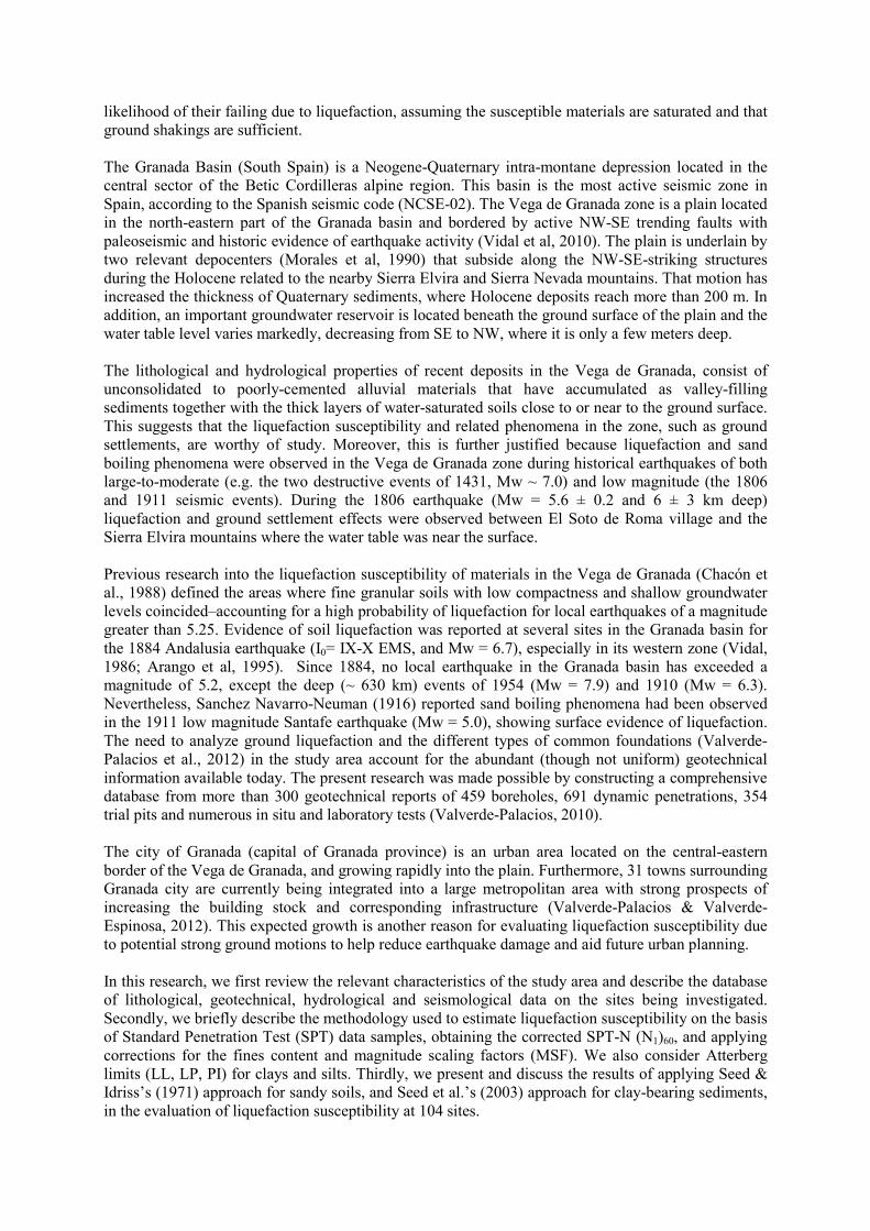
2. GEOLOGICAL SETTING AND ENGINEERING GEOLOGY OF THE STUDY AREA The Granada basin is settled on the central part of the Betic Cordillera. It is one of a set of intra-mountain basins developed in Neogene times during post-orogenic events of tectono-sedimentary deposits. The basin is composed of Miocene age deposits which are more than 2 km thick in some areas (Morales et al., 1990). The Vega de Granada is a predominantly Quaternary plain located in the NE part of the Granada basin. The plain is a highly-irrigated alluvial plain recently deposited along the Genil river and its subsidiaries (Cubillas, Fraile and Colomera streams, Darro River and Aguas Blancas, Monachil and Dilar streams), all descending from the surrounding hills and accumulating thick deposits of eroded material of which those dating from the Holocene are more than 200 m in thickness (Figure 2.1). As a part of the liquefaction susceptibility mapping of the Vega de Granada area, surface geologic and subsurface geotechnical data have been compiled in a database and managed with a geographic information system. This database contains 459 drill holes, where 1556 SPTs were made, and 3586 disturbed and undisturbed samples were obtained for laboratory testing. We have also compiled data from 691 dynamic penetration tests and 354 trenches (Valverde-Palacios, 2010).
Figure 2.1. Spatial distribution of soil units. 7 zones, 10 subzones and borehole location are shown.
The Vega de Granada and its proximal edges present highly heterogeneous geotechnical conditions resulting from lithological, textural and hydro-geological variations. Seven zones and ten sub-zones were defined (Figure 2.1) for 22 areas with different lithologies. The Quaternary alluvial formation is predominant in the study area. Three sub-zones have been distinguished: Zone 1.1: fine alluvial (CL and ML with intercalated [SM and SC] granular levels; Zone 1.2: alluvial fine-granular (alternation of CL-ML and SC, SM and GC, GM); and Zone1.3: coarse alluvial (SM, GW-GM with silt intercalations [ML]). These materials are located on a stretch running WNW-SSE from Láchar to Ogíjares (Figures 2.1, 2.2 –a, b, c- and Table 2.1). The SPT-N values ranged between 5 and 20 blows, corresponding to loose-to-medium density index values (Terzaghi & Peck, 1948) in Zone 1.1, and between 15 and 50 blows, corresponding to medium-dense to very-dense density index values (Terzaghi & Peck, 1948) in Zone 1.3. The ultimate bearing
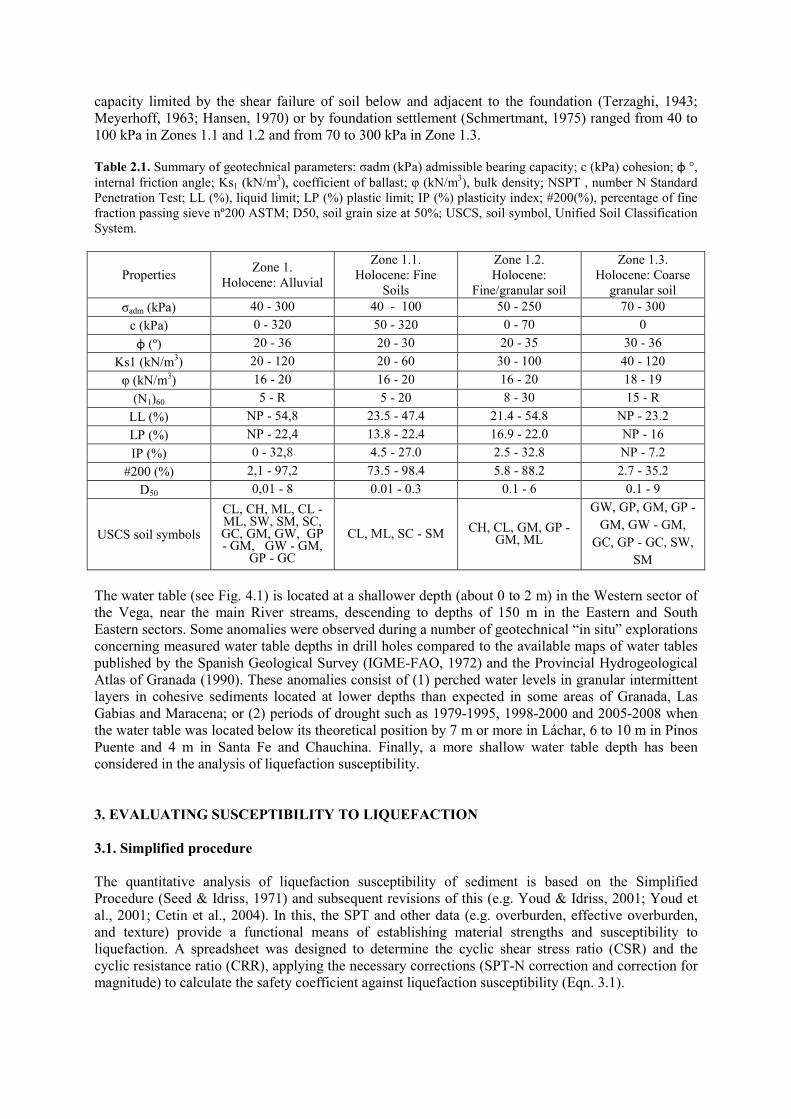
capacity limited by the shear failure of soil below and adjacent to the foundation (Terzaghi, 1943; Meyerhoff, 1963; Hansen, 1970) or by foundation settlement (Schmertmant, 1975) ranged from 40 to 100 kPa in Zones 1.1 and 1.2 and from 70 to 300 kPa in Zone 1.3.
Table 2.1. Summary of geotechnical parameters: σadm (kPa) admissible bearing capacity; c (kPa) cohesion; φ °, internal friction angle; Ks1 (kN/m3), coefficient of ballast; φ (kN/m3), bulk density; NSPT , number N Standard Penetration Test; LL (%), liquid limit; LP (%) plastic limit; IP (%) plasticity index; #200(%), percentage of fine fraction passing sieve nº200 ASTM; D50, soil grain size at 50%; USCS, soil symbol, Unified Soil Classification System.
Properties Zone 1.
Holocene: Alluvial
Zone 1.1. Holocene: Fine
Soils
Zone 1.2. Holocene:
Fine/granular soil
Zone 1.3. Holocene: Coarse
granular soil σadm (kPa) 40 - 300 40 - 100 50 - 250 70 - 300
c (kPa) 0 - 320 50 - 320 0 - 70 0
φ (º) 20 - 36 20 - 30 20 - 35 30 - 36
Ks1 (kN/m3) 20 - 120 20 - 60 30 - 100 40 - 120
φ (kN/m3) 16 - 20 16 - 20 16 - 20 18 - 19
(N1)60 5 - R 5 - 20 8 - 30 15 - R
LL (%) NP - 54,8 23.5 - 47.4 21.4 - 54.8 NP - 23.2
LP (%) NP - 22,4 13.8 - 22.4 16.9 - 22.0 NP - 16
IP (%) 0 - 32,8 4.5 - 27.0 2.5 - 32.8 NP - 7.2
#200 (%) 2,1 - 97,2 73.5 - 98.4 5.8 - 88.2 2.7 - 35.2
D50 0,01 - 8 0.01 - 0.3 0.1 - 6 0.1 - 9
USCS soil symbols
CL, CH, ML, CL - ML, SW, SM, SC, GC, GM, GW, GP - GM, GW - GM,
GP - GC
CL, ML, SC - SM CH, CL, GM, GP - GM, ML
GW, GP, GM, GP -
GM, GW - GM,
GC, GP - GC, SW,
SM
The water table (see Fig. 4.1) is located at a shallower depth (about 0 to 2 m) in the Western sector of the Vega, near the main River streams, descending to depths of 150 m in the Eastern and South Eastern sectors. Some anomalies were observed during a number of geotechnical “in situ” explorations concerning measured water table depths in drill holes compared to the available maps of water tables published by the Spanish Geological Survey (IGME-FAO, 1972) and the Provincial Hydrogeological Atlas of Granada (1990). These anomalies consist of (1) perched water levels in granular intermittent layers in cohesive sediments located at lower depths than expected in some areas of Granada, Las Gabias and Maracena; or (2) periods of drought such as 1979-1995, 1998-2000 and 2005-2008 when the water table was located below its theoretical position by 7 m or more in Láchar, 6 to 10 m in Pinos Puente and 4 m in Santa Fe and Chauchina. Finally, a more shallow water table depth has been considered in the analysis of liquefaction susceptibility. 3. EVALUATING SUSCEPTIBILITY TO LIQUEFACTION
3.1. Simplified procedure The quantitative analysis of liquefaction susceptibility of sediment is based on the Simplified Procedure (Seed & Idriss, 1971) and subsequent revisions of this (e.g. Youd & Idriss, 2001; Youd et al., 2001; Cetin et al., 2004). In this, the SPT and other data (e.g. overburden, effective overburden, and texture) provide a functional means of establishing material strengths and susceptibility to liquefaction. A spreadsheet was designed to determine the cyclic shear stress ratio (CSR) and the cyclic resistance ratio (CRR), applying the necessary corrections (SPT-N correction and correction for magnitude) to calculate the safety coefficient against liquefaction susceptibility (Eqn. 3.1).
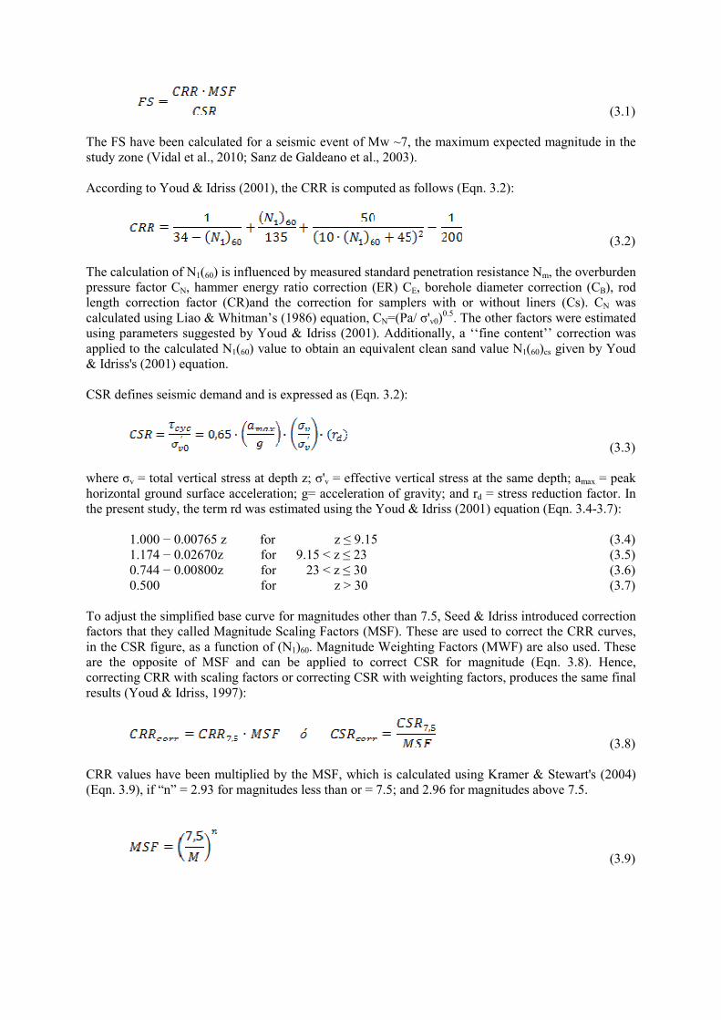
(3.1) The FS have been calculated for a seismic event of Mw ~7, the maximum expected magnitude in the study zone (Vidal et al., 2010; Sanz de Galdeano et al., 2003). According to Youd & Idriss (2001), the CRR is computed as follows (Eqn. 3.2):
(3.2) The calculation of N1(60) is influenced by measured standard penetration resistance Nm, the overburden pressure factor CN, hammer energy ratio correction (ER) CE, borehole diameter correction (CB), rod length correction factor (CR)and the correction for samplers with or without liners (Cs). CN was calculated using Liao & Whitman’s (1986) equation, CN=(Pa/ σ'v0)
0.5. The other factors were estimated using parameters suggested by Youd & Idriss (2001). Additionally, a ‘‘fine content’’ correction was applied to the calculated N1(60) value to obtain an equivalent clean sand value N1(60)cs given by Youd & Idriss's (2001) equation. CSR defines seismic demand and is expressed as (Eqn. 3.2):
(3.3) where σv = total vertical stress at depth z; σ'v = effective vertical stress at the same depth; amax = peak horizontal ground surface acceleration; g= acceleration of gravity; and rd = stress reduction factor. In the present study, the term rd was estimated using the Youd & Idriss (2001) equation (Eqn. 3.4-3.7): 1.000 − 0.00765 z for z ≤ 9.15 (3.4) 1.174 − 0.02670z for 9.15 < z ≤ 23 (3.5) 0.744 − 0.00800z for 23 < z ≤ 30 (3.6) 0.500 for z > 30 (3.7) To adjust the simplified base curve for magnitudes other than 7.5, Seed & Idriss introduced correction factors that they called Magnitude Scaling Factors (MSF). These are used to correct the CRR curves, in the CSR figure, as a function of (N1)60. Magnitude Weighting Factors (MWF) are also used. These are the opposite of MSF and can be applied to correct CSR for magnitude (Eqn. 3.8). Hence, correcting CRR with scaling factors or correcting CSR with weighting factors, produces the same final results (Youd & Idriss, 1997):
(3.8) CRR values have been multiplied by the MSF, which is calculated using Kramer & Stewart's (2004) (Eqn. 3.9), if “n” = 2.93 for magnitudes less than or = 7.5; and 2.96 for magnitudes above 7.5.
(3.9)

3.1. Compositional Criteria
The liquefaction susceptibility criteria formulated by Youd (1998), Andrews & Martin (2000), Seed et al. (2003), Idriss & Boulanger (2004), and Bray & Sancio (2006) were considered to soil elements up to 15 m from the boreholes. Seed et al.'s (2003) criteria have been adopted. These suggest a soil layer is likely to liquefy when the LL is less than 37%, the PI less than 12%, and when 37<LL<47 and 12<PI<20. Figure 3.1 shows the distribution of soil layers on the basis of their LL and PI. The areas prone to liquefaction soils are plotted with solid squares, non-liquefiable soils are plotted with open circles, and soils which require laboratory tests to check their behavior are plotted with open triangles.
Figure 3.1. Liquefaction susceptibility criteria using Seed et al. limits. 4. LIQUEFACTION SUSCEPTIBILITY MAPPING When defining the zones, characterized by the in situ and laboratory tests, we need to establish a series of premises to calculate liquefaction susceptibility: - Seismic accelerations greater than 0.16g, a figure which is surpassed throughout the study zone (NCSE-02). - Soil type: sandy soils with low fines content, although liquefaction can occur in clay soils and/or silts that meet the established criteria. In this case we have used Seed et al.'s (2003) criteria, finding soils susceptible to liquefaction in a clay and/or silt layer located between 2 and 9 m from the surface. - Water level near the surface. A priori, this premise has been used to establish the relevant zones when calculating susceptibility, either to test established recommendations in the case of fine soils, or to estimate the FS in the case of granular soils. However, in the potential risk zone we have included areas where the water level is deeper (up to about 8 m) as we have detected materials that fulfil the conditions for liquefaction with water levels at the depth indicated (see Fig. 4.1). Finally, we have calculated liquefaction susceptibility at 104 sites, fundamentally using the value of (N1)60 based on the SPT-N (Fig. 4.1), fines content (% that passes through a #200 ASTM sieve), water level depth (Fig. 4.1), depth of analysis and magnitude of the earthquake being studied. Following the analysis, a map (Fig. 4.2) of areas susceptible to liquefaction was drawn up, classifying these as liquefiable, potentially liquefiable, and non-liquefiable. The liquefiable areas are found in the
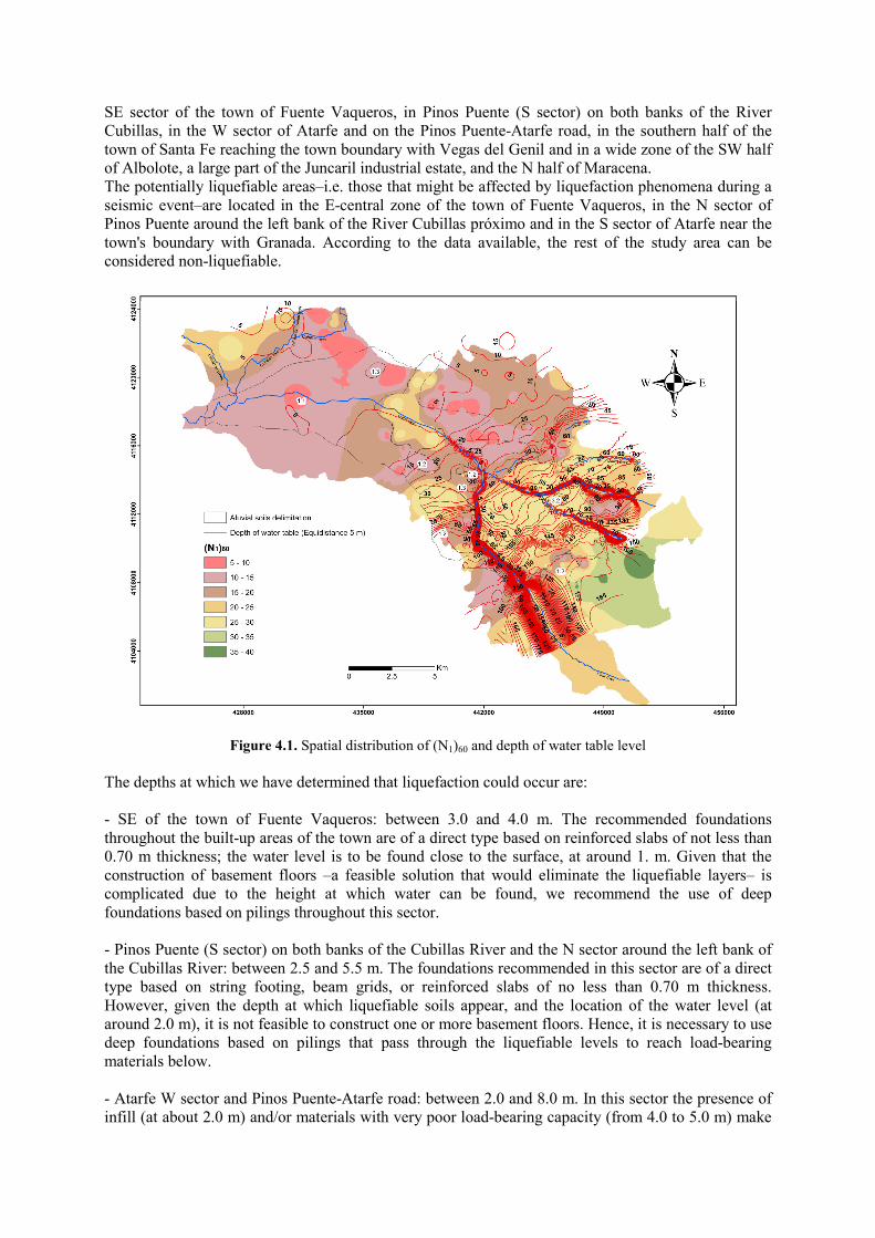
SE sector of the town of Fuente Vaqueros, in Pinos Puente (S sector) on both banks of the River Cubillas, in the W sector of Atarfe and on the Pinos Puente-Atarfe road, in the southern half of the town of Santa Fe reaching the town boundary with Vegas del Genil and in a wide zone of the SW half of Albolote, a large part of the Juncaril industrial estate, and the N half of Maracena. The potentially liquefiable areas–i.e. those that might be affected by liquefaction phenomena during a seismic event–are located in the E-central zone of the town of Fuente Vaqueros, in the N sector of Pinos Puente around the left bank of the River Cubillas próximo and in the S sector of Atarfe near the town's boundary with Granada. According to the data available, the rest of the study area can be considered non-liquefiable.
Figure 4.1. Spatial distribution of (N1)60 and depth of water table level
The depths at which we have determined that liquefaction could occur are: - SE of the town of Fuente Vaqueros: between 3.0 and 4.0 m. The recommended foundations throughout the built-up areas of the town are of a direct type based on reinforced slabs of not less than 0.70 m thickness; the water level is to be found close to the surface, at around 1. m. Given that the construction of basement floors –a feasible solution that would eliminate the liquefiable layers– is complicated due to the height at which water can be found, we recommend the use of deep foundations based on pilings throughout this sector. - Pinos Puente (S sector) on both banks of the Cubillas River and the N sector around the left bank of the Cubillas River: between 2.5 and 5.5 m. The foundations recommended in this sector are of a direct type based on string footing, beam grids, or reinforced slabs of no less than 0.70 m thickness. However, given the depth at which liquefiable soils appear, and the location of the water level (at around 2.0 m), it is not feasible to construct one or more basement floors. Hence, it is necessary to use deep foundations based on pilings that pass through the liquefiable levels to reach load-bearing materials below. - Atarfe W sector and Pinos Puente-Atarfe road: between 2.0 and 8.0 m. In this sector the presence of infill (at about 2.0 m) and/or materials with very poor load-bearing capacity (from 4.0 to 5.0 m) make
it a priori essential to use deep foundations based on pilings. No other measures are therefore needed. - SSE half of the town of Santa Fe: between 6.0 and 9.0 m. In this sector the location of the water level ranges from 6.0 to 13.0 m. Generally, we would recommend the use of deep foundations based on pilings that pass through the levels susceptible to liquefaction, which are of very low consistency, reaching levels of more competent granular soils that can be detected at around 24.0 m. - SW half of Albolote town, most of the Juncaril industrial estate and the N half of Maracena town: between 1.0 and 4.5 m–although in the SE sector of the Juncaril estate, once the low load-bearing capacity infill has been traversed, our calculations predict possible liquefaction at around 9 m depth. In this case the water level is located at between 2 and 10 m, and the recommended foundations include reinforced slabs, string footing and pilings (presence of anthropic infill and materials of very poor load-bearing capacity). As a general rule, we recommend the construction of deep foundations based on pilings in those zones where no previously established recommendations exist and water is found at above 6.0 m. In the remaining cases, we recommend direct foundations such as string footing, beam grids or reinforced slabs of not less than 0.70 m thickness.
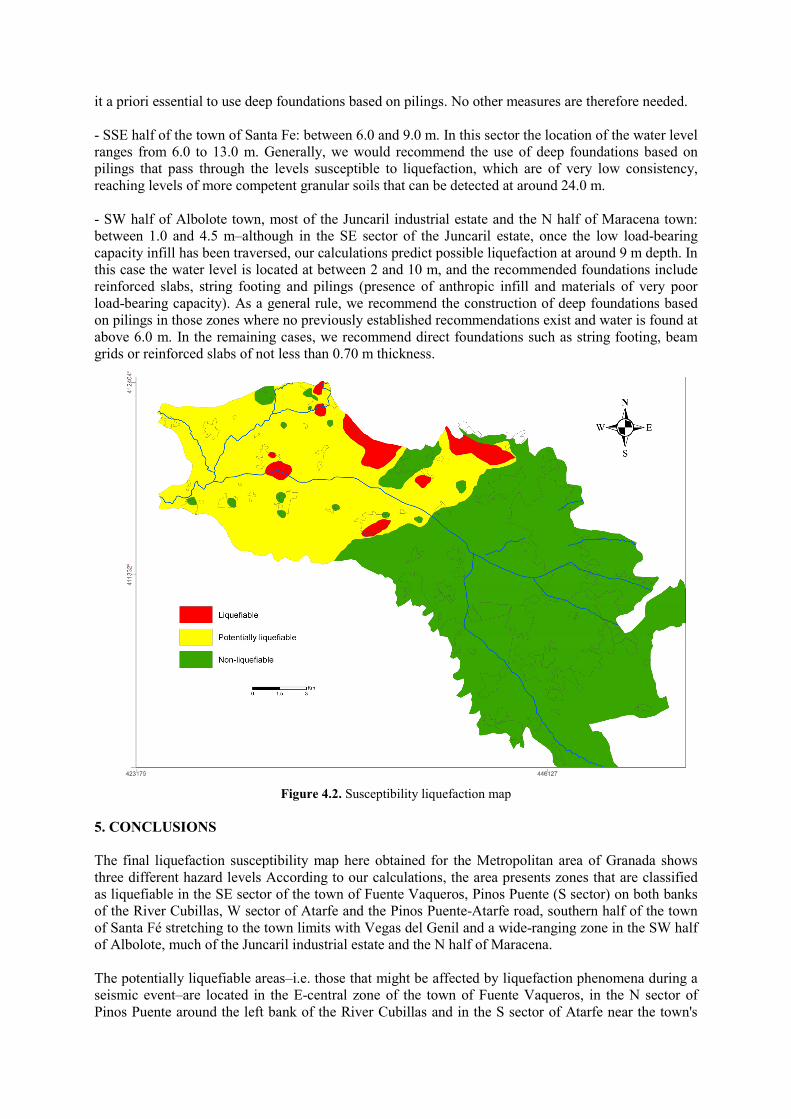
Figure 4.2. Susceptibility liquefaction map
5. CONCLUSIONS
The final liquefaction susceptibility map here obtained for the Metropolitan area of Granada shows three different hazard levels According to our calculations, the area presents zones that are classified as liquefiable in the SE sector of the town of Fuente Vaqueros, Pinos Puente (S sector) on both banks of the River Cubillas, W sector of Atarfe and the Pinos Puente-Atarfe road, southern half of the town of Santa Fé stretching to the town limits with Vegas del Genil and a wide-ranging zone in the SW half of Albolote, much of the Juncaril industrial estate and the N half of Maracena. The potentially liquefiable areas–i.e. those that might be affected by liquefaction phenomena during a seismic event–are located in the E-central zone of the town of Fuente Vaqueros, in the N sector of Pinos Puente around the left bank of the River Cubillas and in the S sector of Atarfe near the town's
boundary with Granada. The rest of the the study area, according to the data available can be considered non-liquefiable. However, the liquefiable or potentially liquefiable zones may occupy a larger area than indicated because for some sectors, such as the centre of the Vega de Granada (a zone within the town limits of Fuente Vaqueros, Chauchina, Atarfe and Santa Fé), we have no information from field or laboratory tests, although the position of the water level and the type of material could be said to be potentially liquefiable, but we would need more information to confirm this. Vidal et al. (2010) have analyzed the effects of site associated with the earthquake that occurred in Santa Fé in 1806 (I=VIII and M=5.6 ± 0.2) by reviewing historic texts held in town and church archives. One of their conclusions is that liquefaction-related phenomena can be identified in the sector between Fuente Vaqueros and the Sierra Elvira mountains–sectors that coincide with those detected in the calculations made in the present study. Moreover, a strong correlation exists with the zone demarcation of earlier research conducted by Chacón et al. (1988). The results of our susceptibility hazard mapping indicate that large zones of the Vega de Granada may be vulnerable to liquefaction-related phenomenon resulting from strong earthquake-induced ground shaking. These results can help in earthquake damage reduction and to aid future urban planning. REFERENCES Ambraseys, N. N. (1988). Engineering seismology. Earthquake Engrg.and Struct. Dynamic, 17. Andrews, D. C., and Martin, G. R. (2000). Criteria for liquefaction of silty soils. 12th World Conf. on
Earthquake Engineering. Upper Hutt, New Zealand: NZ Soc. for EQ Engrg., Paper No. 0312. Andrus, R. D., and Stokoe, K. H. (2000). Liquefaction resistance of soils from shear-wave velocity. Journal of
geotechnical and geoenvironmental engineering , 126:11, 1015-1025. Arango, I. (1996). Magnitude scaling factors for soil liquefaction evaluations. Journal of Geotechnical
Engineering , 122:11, 929-936. Bol, E., Önalp, A., Arel, E., Sert, S. and Özocak, A. (2010). Liquefaction of silts: The Adapazari criteria.
Bulletin of Earthquake Engineering, 8:4, 859-873. Bray, J. D., and Sancio, R. B. (2006). Assessment of the Liquefaction Susceptibility of Fine-Grained Soils.
Journal of Geotechnical and Geoenvironmental Engineering , 132:9, 1165-1177. Cetin, K.O., Seed, R.B., Der Kiureghian, A., Tokimatsu, K., Harder Jr., L.F., Kayen, R.E. And Moss, R.E.S..
(2004). Standard penetration test-based probabilistic and deterministic assessment of seismic soil liquefaction potential. Journal of Geotechnical and Geoenvironmental Engineering, 130:12, 1314-1340.
Chacón, J., Casado, C. L., Rodríguez-Moreno, I., and Irigaray, C. (1988). Geotechnical site conditions and seismic microzonation of the Granada basin (Spain). In Carlos S.Oliveira (edt). Proc. ECE/UN Seminar on Prediction of Earthquakes: Occurrence and Ground Motion, 1, part. 3., págs. 449-460. Lab. Nac.Eng.Civil. Lisboa, Portugal.
Hansen, J. B. (1970). A revised and extended formula for bearing capacity. Geotecnisk Inst. Hou, L., Li, A., Xu, H., He, C. and Hu, P., (2011). Recent advances in gravelly soils liquefaction evaluation.
Applied Mechanics and Materials, 90-93, 1443-1446 Hunt, R. E. (1884). Geotechnical engineering investigation manual. McGraw-Hill Book Co. Idriss, I. M., and Boulanger, R. W. (2004). Semi-empirical procedures for evaluating liquefaction potential
during earthquakes . 11th International Conference on Soil Dynamics & Earthquake Engineering and The 3rd International Conference on Earthquake Geotechnical Engineering, (págs. 32-56). Berkeley, California.
Idriss, I.M. and Boulanger, R.W. (2008). Soil Liquefaction during Earthquakes, EERI Publication (2008), 235 pp.
Kramer, S., and Stewart, J. (2004). Geotechnical Aspects of Seismic Hazards. En Y. Bozorgnia, & V. Bertero, Earthquake Engineering: From Engineering Seismology to Performance-Based Engineering. London. Taylor and Francis Group.
Meyerhof, G. G. (1963). Some recent research on the bearing capacity of foundations. The ultimate bearing capacity of foundations. Can. Geotech. 16-26.
Moradi, G., Khatibi, B.R. and Sutubadi, M.H. (2011). Determination of liquefaction potential of soil using (N1)60 by numerical modeling method. Electronic Journal of Geotechnical Engineering, 16 D, 407-417.
Morales, J., Seo, K., Samano, T., Peña, J. A., Ibañez, J. M., and Vidal, F. (1993). Site response on seismic motion in the Granada basin (southern Spain) based on microtremor measurements. Journal of Physics of the Earth , 41:4, 221-238.
Papathanassiou, G. and Valkaniotis, S., 2010. Liquefaction hazard mapping at the town of Edessa, Northern Greece. Natural Hazards, 53:11, 109-123.
Robertson, P. K., and Wride, C. E. (1998). Evaluating cyclic liquefaction potential using cone penetration test. Journal Canadian Geotechnical , 35:3, 442-459.
Sanz De Galdeano, C., Peláez Montilla, J. A., and López Garrido, A. C. (Edits.). (2001). La Cuenca de Granada. Estructura, Tectónica activa, Sismicidad, Geomorfología y dataciones existentes. Granada.
Sanz De Galdeano, C., Peláez Montilla, J. A., and López Casado, C. (2003). Seismic Potential of Main Acive Faults in the Granada Basin (Southern Spain). Pure Appl. Geophys. 160, 1537-1556.
Schmertmann, J. H. (1978). Measurement of in situ shera strength. Proc. of Conference on In situ Measurement of Soil Properties. ASCE. New York.
Seed, H. B., and Idriss, I. M. (1971). Simplified procedure for evaluating soil liquefaction potential. J. Soil. Mech. and Found. Div., ASCE , 1249-1273.
Seed, H. B., and Idriss, I. M. (1982). Ground motions and soil liquefaction during earthquakes. Berkeley, Calif.: Earthquake Engineering Research Institute.
Seed, R B; Cetin, K O; Moss, R E. S.; Kammerer, A M; Wu, J; Pestana, J M; Riemer, M F; Sancio, R B; Bray, J D; Kayen, R E; and Faris, A. (2003). Recent advances in soil liquefaction engineering: a unified and consistent framework. Report Nº. EERC 2003-06. University of California. Berkeley, Calif.
Terzaghi, K. (1943). Theoretical Soil Mechanics. New York: John Wiley and Sons. Terzaghi, K., and Peck, R. B. (1948). Soil Mechanics in Engineering Practice. John Wiley, New York, 566 pp Valverde Palacios, I. (2010). Cimentaciones de edificios en condiciones estáticas y dinámicas. Casos de estudio
al W de la ciudad de Granada. Universidad de Granada (España). Tesis Doctoral. Valverde-Palacios, I., Chacón, J., Valverde-Espinosa, I. and Irigaray, C. (2012) Foundation models in seismic
areas: Four case studies near the city of Granada (Spain), Engineering Geology. 131-132, 57-69 Valverde-Palacios, I. and Valverde-Espinosa, I. (2012). Increase of seismic risk for growth of a large
metropolitan area of Granada (Spain). Case studies. Journal Earth Science Research (ESR), Canadian Center of Science and Education. In Press.
Vidal, F., Espinar, M., Morcillo, J. and Navarro, M. (2010). The 1806 Santa Fe (Spain) earthquake and site-related effects. 9Th Internacional Workshop on Seismic Microzoning Risk Reduction, Cuernavaca, México.
Vipin, K.S., Sitharam, T.G. and Anbazhagan, P. (2010). Probabilistic evaluation of seismic soil liquefaction potential based on SPT data. Natural Hazards, 53:3, 547-560.
Youd, T. L., & Idriss, I. M. (1997). Workshop on Evaluation of Liquefaction Resistance of Soils. Proceedings of
the NCEER 97-0022. Buffalo, N.Y. National Center for Earthquake Engineering Research. Youd, T. L., and Noble, S. K. (1997). Magnitude scaling factors. Proc., NCEER Workshop on Evaluation of
Liquefaction Resistance of Soils, Nat. Ctr. for Earthquake Engrg. Res., State Univ. of New York at Buffalo, 149–165.
Youd, T. L. (1998). Screening guide for rapid assessment of liquefaction hazard at highway bridge sites. Technical Rep. MCEER-98-0005. Multidisciplinary Center for Earthquake Engineering Research. Buffalo, N.Y.
Youd, T. L. and Idriss, I. M. (2001). Liquefaction resistance of soils: summary report from the 1996 NCEER and 1998 NCEER/NSF workshops on evaluation of liquefaction resistance of soils. Journal of Geotechnical and Geoenvironmental Engineering , 127:4, 297-313.
Youd T.L., Idriss I.M., Andrus R.D., Arango I., Castro G., Christian J.T., Dobry R., Finn W.D.L., Harder L.F., Hynes M.E., Ishihara K., Koester J.P., Liao S.S.C., Marcurson W.F.Iii., Marti G.R., Mitchell J.K., Moriwaki Y., Power M.S., Robertson P.K., Seed R.B., and Stokoe K.H.Ii. (2001) Liquefaction resistance of soils: summary report from the 1996 NCEER and 1998 NCEER/NSF workshops on evaluation of liquefaction resistance of soils. J Geotech Geoenv Eng ASCE, 127:10, 817–833.


![docs.assembly.ab.ca · Claimant Name: Yasin Cetin Expense Category: Hosting For hosting, select one: C] Individual Constituent(s) Individual Stakeholder(s) C] Group: Constituency](https://img.pdfslide.us/doc/110x75/60732ca978f493113433166b/docs-claimant-name-yasin-cetin-expense-category-hosting-for-hosting-select-one.jpg)