Embed Size (px)
Citation preview
EUROGRAPHICS 2017 / L. Barthe and B. Benes(Guest Editors)
Volume 36 (2017), Number 2
Sparse Inertial Poser:Automatic 3D Human Pose Estimation from Sparse IMUs
T. von Marcard1 B. Rosenhahn1 M. J. Black2 G. Pons-Moll2
1Institut für Informationsverarbeitung (TNT), Leibniz-Universität Hannover, Germany2Max Planck Institute for Intelligent Systems, Tübingen, Germany
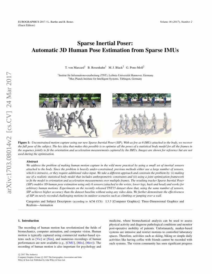
Figure 1: Unconstrained motion capture using our new Sparse Inertial Poser (SIP). With as few as 6 IMUs attached to the body, we recoverthe full pose of the subject. The key idea that makes this possible is to optimise all the poses of a statistical body model for all the frames inthe sequence jointly to fit the orientation and acceleration measurements captured by the IMUs. Images are shown for reference but are notused during the optimisation.
AbstractWe address the problem of making human motion capture in the wild more practical by using a small set of inertial sensorsattached to the body. Since the problem is heavily under-constrained, previous methods either use a large number of sensors,which is intrusive, or they require additional video input. We take a different approach and constrain the problem by: (i) makinguse of a realistic statistical body model that includes anthropometric constraints and (ii) using a joint optimization frameworkto fit the model to orientation and acceleration measurements over multiple frames. The resulting tracker Sparse Inertial Poser(SIP) enables 3D human pose estimation using only 6 sensors (attached to the wrists, lower legs, back and head) and works forarbitrary human motions. Experiments on the recently released TNT15 dataset show that, using the same number of sensors,SIP achieves higher accuracy than the dataset baseline without using any video data. We further demonstrate the effectivenessof SIP on newly recorded challenging motions in outdoor scenarios such as climbing or jumping over a wall.
Categories and Subject Descriptors (according to ACM CCS): I.3.3 [Computer Graphics]: Three-Dimensional Graphics andRealism—Animation
1. Introduction
The recording of human motion has revolutionized the fields ofbiomechanics, computer animation, and computer vision. Humanmotion is typically captured using commercial marker-based sys-tems such as [Vic] or [Sim], and numerous recordings of humanperformances are now available (e.g., [CMU], [Mix], [Mov]). Therecording of human motion is also important for psychology and
medicine, where biomechanical analysis can be used to assessphysical activity and diagnose pathological conditions and monitorpost-operative mobility of patients. Unfortunately, marker-basedsystems are intrusive and restrict motions to controlled laboratoryspaces. Therefore, activities such as skiing, biking or simple dailyactivities like having coffee with friends cannot be recorded withsuch systems. The vision community has seen significant progress
c© 2017 The Author(s)Computer Graphics Forum c© 2017 The Eurographics Association and JohnWiley & Sons Ltd. Published by John Wiley & Sons Ltd.
arX
iv:1
703.
0801
4v2
[cs
.CV
] 2
4 M
ar 2
017
v. Marcard et al. / Sparse Inertial Poser:Automatic 3D Human Pose Estimation from Sparse IMUs
in the estimation of 3D human pose from images, but this typi-cally involves multi-camera calibrated systems, which again limitapplicability. Existing methods for estimating 3D human pose fromsingle images, e.g. [BKL∗16], are still less accurate than motioncapture systems. However, to record human motion in everyday sit-uations and in natural settings one would need a dedicated camerato track a specific subject. Hence, it is unlikely that vision-basedsystems will be able to record large amounts of continuous dailyactivity data.
Systems based on Inertial Measurement Units (IMUs) do notsuffer from such limitations; they can track the human pose with-out cameras which make them more suitable for outdoor record-ings, scenarios with occlusions, baggy clothing or where trackingwith a dedicated camera is simply not possible. However, inertialmeasurement systems such as Xsens BioMech [Xse] are quite in-trusive, requiring 17 sensors worn on the body or attached to a suit.This is one of the reasons that large amounts of data have not beenrecorded yet. Hence, a less intrusive solution that can capture peo-ple through occlusions is needed.
In this paper, we present the Sparse Inertial Poser (SIP), amethod to recover the full 3D human pose from only 6 IMUs.Six sensors, measuring orientation and acceleration are attachedto the wrists, lower legs, waist and head, resulting in a minimallyintrusive solution to capture human activities. Furthermore, manyconsumer products already have IMUs integrated, e.g., fitness andsmartwatches, smartphones, Google glasses and Oculus rift. Our 6-sensor system could easily be worn with a hat or glasses, two wristbands, a belt, and shoe or ankle sensors. However, recovering hu-man pose from only 6 IMUs is a very difficult task. Orientation atthe extremities and waist only provides a weak constraint on thehuman motion and incorporation of acceleration data is usually af-fected by drift.
To solve this problem, we exploit the rich statistical SMPL bodymodel [LMR∗15]. One key insight is that the body model can befit to incomplete and ambiguous data because it captures informa-tion about the kinematic constraints of the human body. A similarobservation has been made by [TST∗15] and [TBC∗16] who lever-aged a statistical model for hand pose tracking. Unfortunately, thisalone is not sufficient to compensate for drift. Most previous meth-ods (e.g. [RLS07,VAV∗07]) integrate acceleration frame by frame,which results in unstable estimates when using very few sensors.Optimizing frame by frame is similar to a double explicit inte-gration scheme, which is known to be unstable and only accuratewithin small time intervals.
We take a different approach and optimize all the poses of allthe frames of a sequence at once. Hence, our objective functionenforces the coherency between the body model orientation andacceleration estimates against the IMU recordings. Effectively, therealistic body model simplifies the estimation problem, providingsufficient constraints to solve the problem from sparse measure-ments, even for complex movements. Some examples are shown inFig. 1.
In several experiments we show that SIP, while simple, is verypowerful and can recover all the poses of a sequence as a resultof a single optimization. We report results on the recently releasedTNT15 dataset [MPMR16] which features 4 subjects wearing 10
IMUs performing a variety of human actions. To evaluate SIP weuse 6 IMUs for tracking and 4 IMUs for validation. We compare totwo baselines, namely an orientation-only tracker that uses only theorientation information and a variant of SIP that uses a different hu-man body model. Qualitative and quantitative results demonstratethat SIP is significantly more accurate than the baselines. To furtherdemonstrate the applicability of SIP, we present additional trackingresults of two subjects wearing 6 IMUs in an outdoor setting (seeFig. 1).
In summary, SIP makes the challenging problem of human poseestimation from sparse IMU data feasible by:
• Making use of a realistic body model that incorporates anthro-pomorphic constraints (with a skeletal rig).
• A joint optimization framework that fits the poses of a bodymodel to the orientation and acceleration measurements overmultiple frames.
Altogether SIP is the first method that is able to estimate the 3Dhuman pose from only 6 IMUs without relying on databases ofMoCap or learning methods that make strong assumptions aboutthe recorded motion.
2. Related Work
The literature on human pose estimation from images is vast andin this paper we focus only on methods integrating multiple sen-sor modalities and methods predicting full pose from sparse lowdimensional control signals.
2.1. Database retrieval and learning based methods
Some work has focused on recovering full pose from sparse incom-plete sensor signals. In [SH08, TZK∗11] they reconstruct humanpose from 5 accelerometers by retrieving pre-recorded poses withsimilar accelerations from a database. Acceleration data is howeververy noisy and the space of possible accelerations is huge whichmakes learning a very difficult task. A somewhat easier problemis addressed in [CH05]; they reconstruct full 3D pose from a setof sparse markers attached at the body. They build online localPCA models using the sparse marker locations as input to query thedatabase of human poses. This approach works well since the 5-10marker locations can constrain the pose significantly; furthermorethe mapping from 3D locations to pose is much more direct thanfrom acceleration data. Unfortunately, this approach is restrictedto a lab with cameras capturing the reflective markers. Followingsimilar ideas, in [LWC∗11] they regress to full pose using onlinelocal models but using 6 IMUs to query the database. In [SMN09]they directly regress full pose using only 4 IMUs with GaussianProcess regression. Both methods report very good results whenthe test motions are present in the database. In [HKP∗16] they ex-tract gait parameters using deep convolutional neural networks. Al-though pre-recorded human motion greatly constrains the problem,methods that heavily rely on pre-recorded data are limited; in par-ticular capturing arbitrary activities is difficult if it is missing in thedatabases.
c© 2017 The Author(s)Computer Graphics Forum c© 2017 The Eurographics Association and John Wiley & Sons Ltd.
v. Marcard et al. / Sparse Inertial Poser:Automatic 3D Human Pose Estimation from Sparse IMUs
2.2. Full-body IMU MoCap
There exist commercial solutions for human motion capture fromIMUs; [RLS07] use 17 IMUs equipped with 3D accelerometers,gyroscopes and magnetometers and all the measurements are fusedusing a Kalman Filter. By achieving stable orientation measure-ments the 17 IMUs completely define the pose of the subject. How-ever it is very intrusive for a subject to wear them, and long setuptimes are required. In the seminal work of [VAV∗07] they propose acustom made system consisting of 18 sensor boards, each equippedwith an IMU and acoustic distance sensors, to compensate for typi-cal drift in the orientation estimates. While the approach is demon-strated in challenging outdoor settings like ours, the system is alsovery intrusive and difficult to reproduce. Other approaches havecombined sparse IMUs with video input [PMBG∗11,MPMR16] orsparse optical markers [AHK∗16] to constrain the problem. Simi-larly [HMST13] combines sparse IMUs with a depth camera. IMUsare only used to query similar poses in a database and depth datais used to obtain the full pose. While powerful, using video inputdoes not allow human movements to be captured with occlusions orin applications that require continuous activity monitoring. Hence,instead of constraining the problem using additional sensors, weconstrain the problem by using a statistical body model and opti-mizing the pose over multiple frames. While 6 IMUs do not provideenough constraints to determine the full pose for a single frame, wefind that accurate pose estimates can be obtained when integratingall orientation and acceleration measurements into a single opti-mization objective.
3. Background
3.1. Exponential Map on SO(3) and SE(3)
In this section we quickly review the concept of exponential map-ping on the Special Orthogonal Group SO(3) and the Special Eu-clidean Group SE(3). The exponential map representation providesa geometric and elegant treatment of rigid body motion, which weuse to relate pose parameters to human body motions. Using theexponential map has some advantadges for optimization w.r.t. otherrepresentations such as Euler angles [PMR09]; for more details onthe exponential mapping and a comparison to other parameteriza-tions we refer the reader to [MLSS94, PMR11].
Both SO(3) and SE(3) are Lie groups with an associatedLie algebra. Throughout this paper we will use the cross-operator × to construct a Lie algebra element from its coordi-nates and the vee-operator ∨ to extract the coordinates of a Liealgebra element into a column vector. The group of rotationsabout the origin in 3 dimensions SO(3) is defined as SO(3) ={R ∈ R3×3 :RT R = I,det(R) = 1}. Every rotation R can be ex-pressed in exponential form
R = exp(ω×), (1)
where ω× ∈ so(3) is a skew-symmetric matrix and can be com-
puted analytically using the Rodriguez Formula [MLSS94]. Thethree independent parameters ω ∈ R3 of ω
× are called exponen-tial coordinates of R and define the axis of rotation and ||ω|| is theangle of rotation about this axis. The group SE(3) represents rigidbody motions composed by a rotation R ∈ SO(3) and translation
(a) (b)
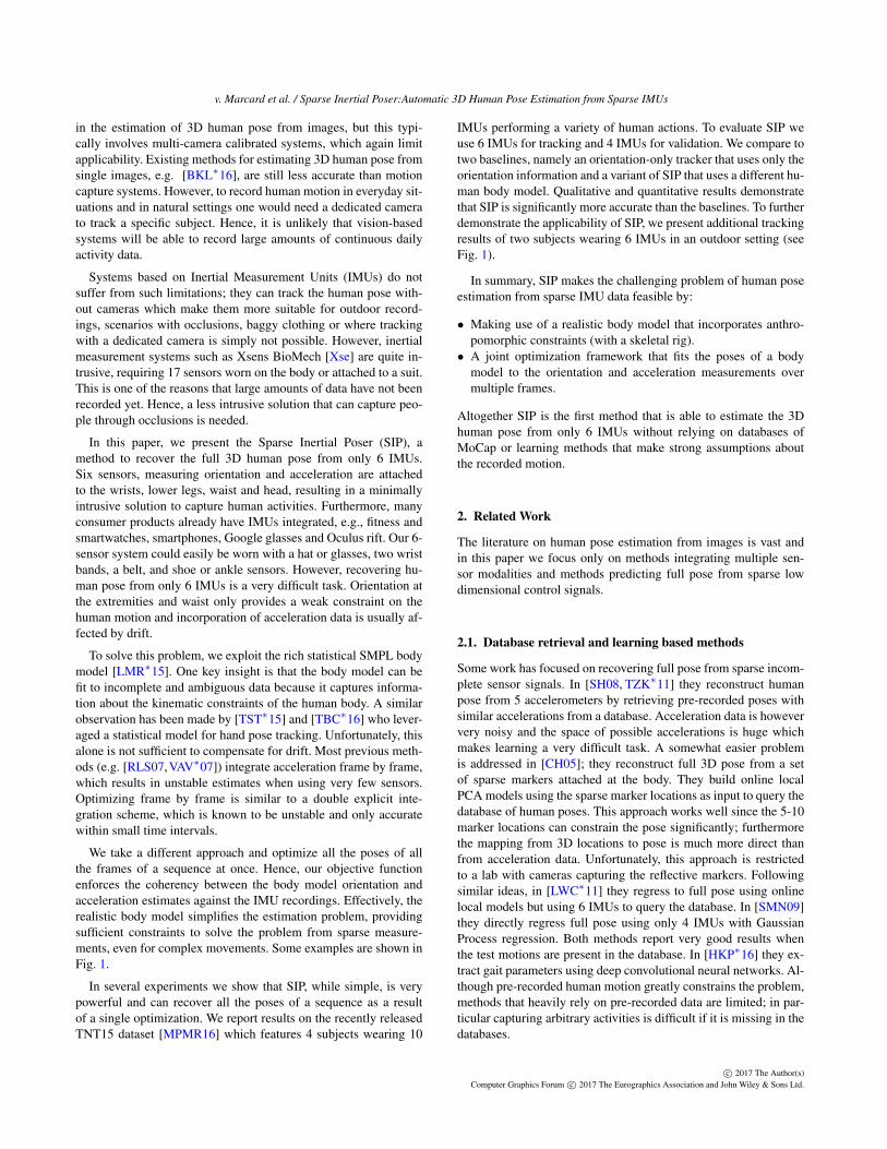
Figure 2: (a) The joints of the skeleton in SMPL are predicted asa function of the surface. This allows us to obtain accurate jointlocations which are used to predict the acceleration measurements.(b) Manually rigged models lead to worse performance fitting in-complete sensor measurements.
t ∈ R3. Any rigid motion G ∈ R4×4 can be written in exponentialform
G =
[R t0 1
]= exp(ξ×), (2)
where ξ× ∈ se(3) is called the associated twist action and se(3)
refers to the corresponding Lie algebra. The six independent pa-rameters ξ ∈ R6 of ξ
× are called exponential coordinates of G.They are composed of the rotational parameters ω∈R3 and v∈R3,where the latter encodes location of the axis of rotation and trans-lation along the axis.
The inverse operation of Eq. (1) and Eq. (2) is the logarithm andrecovers a Lie algebra element from a Lie group element. We alsointroduce the Taylor expansion of the matrix exponential given by
exp(ξ×) = I+ξ×+
(ξ×)2
2!+
(ξ×)3
3!+ . . . , (3)
and the first-order approximation for the logarithm
log(exp(δω×)exp(ω×))∨ ≈ δω+ω, (4)
for a small δω ∈ R3.
3.2. SMPL Body Model
SMPL [LMR∗15] is a body model that uses a learned template withV = 6890 vertices T, and a learned rigged template skeleton. Theactual vertex positions of SMPL are adapted according to identity-dependent shape parameters and the skeleton pose. The skeletalstructure of the human body is modeled with a kinematic chain con-sisting of rigid bone segments linked by n = 24 joints. Each joint ismodeled as a ball joint with 3 rotational Degrees of Freedom (DoF),parametrized with exponential coordinates ω. Including translation,the pose x is determined by a pose vector of d = 3×24+3= 75 pa-rameters. The rigid motion GT B(x) of a bone depends on the statesof parent joints in the kinematic chain and can be computed by the
c© 2017 The Author(s)Computer Graphics Forum c© 2017 The Eurographics Association and John Wiley & Sons Ltd.
v. Marcard et al. / Sparse Inertial Poser:Automatic 3D Human Pose Estimation from Sparse IMUs
forward kinematic map GT B : Rd → SE(3):
GT B(x) =
(∏
j∈I(i)
[exp(ω×j ) j
~0 1
])=
(∏
j∈I(i)exp(
ξ×j
)),
(5)where I(i)⊆ {1, · · · ,n+1} is an ordered set of parent joints, ω j ∈R3 are the exponential coordinates of the joint rotation, j ∈ R3 isthe joint location and ξ
×j ∈ se(3) is the twist action of joint j. The
initial offset between the bone and the tracking frame is the identity.
SMPL models body shape variation using shape blend shapes,that are linearly added to the template mesh. A new subject shapeis typically obtained by adding a linear combination of blendshapesSi ∈ R3V to the template mesh T′ = T+∑i βiSi. SMPL automat-ically predicts the joint locations Q = [jT
1 . . . jTn ]
T as a function ofthe surface mesh using a sparse regression matrix Q = JT′. Whilethe orientation of the limbs do not depend at all on the body joints,the linear acceleration of a particular part of the body depends onthe joint locations. By using SMPL we can track any shape withouthaving to manually edit the skeleton, see Figure 2(a).
3.3. IMUs
An Inertial Measurement Unit (IMU) is a device that is com-monly equipped with 3-axes accelerometers, gyroscopes and mag-netometers. It measures acceleration, rate of turn and magnetic fieldstrength with respect to the IMU-aligned sensor coordinate systemFS. Typically, a Kalman Filter is then applied to track the sensororientation with respect to a global inertial coordinate system F I .
In order to utilize IMU data together with the body model weintroduce several coordinate systems depicted in Figure 3(a). Thebody model is defined in the global tracking coordinate system FG
and each bone segment of the body has a local coordinate systemFB. The map GGB : FB → FG defines the mapping from bone totracking coordinate system. Equivalently, GIS : FS → F I definesthe mapping from the local IMU sensor coordinate system FS toF I . Both global coordinate systems FG and F I are related by theconstant mapping GGI : F I→ FG. In the following we will assumeGGI is known and express all IMU readings in the global trackingframe FG using the transformation rule
GGS(t) = GGIGIS(t). (6)
For a more detailed description of relating inertial data to other sen-sor or model coordinate systems we refer the reader to [BHM∗10].Our aim is to find a pose trajectory such that the motion of a limbis consistent with IMU acceleration and orientation attached to it.Thus we need to know the offset between IMU and its correspond-ing bone coordinate system GBS(t) : FS → FB. We assume that itis constant as the sensors are tightly attached to the limbs and com-pute it at the first frame of the tracking sequence according to
GBS = GBG(0)GGS(0). (7)
4. Sparse Inertial Poser
Recovering full pose from only N = 6 IMUs (strapped at lowerarms, lower legs, head and waist) is highly ambiguous. Assumingno sensor noise, orientation data only constrains the full pose to lie
FT
FB
FS
GIS
GT I
GT B
GBS
F I
(a) (b)
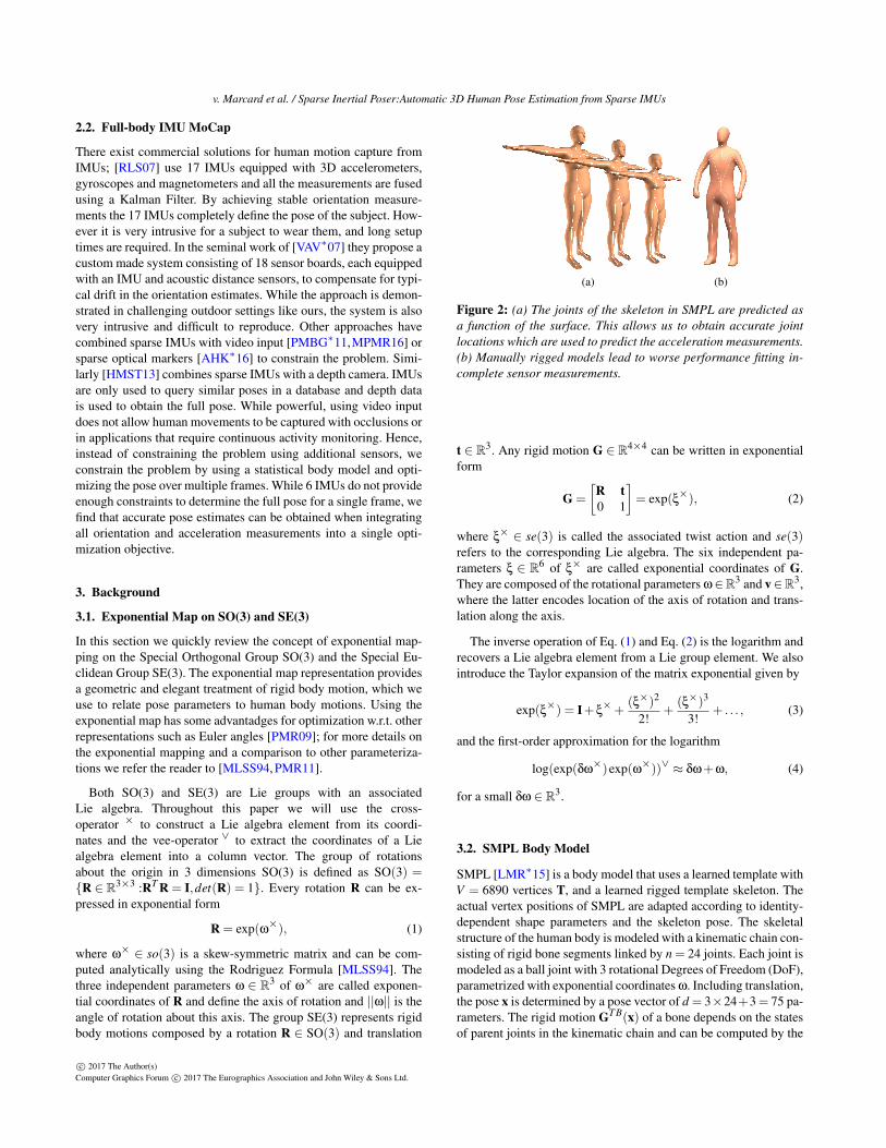
Figure 3: (a) Coordinate frames: Global tracking coordinateframe FG, Inertial coordinate frame F I , Bone coordinate frameFB and Sensor coordinate frame FS. (b) Sensor placement at head,lower legs, wrists and back.
0 50 100 150 200
1
1.5
2
0 50 100 150 200
-1
0
1
2
Figure 4: Y- and Z-coordinates of the left wrist sensor position(Y pointing upwards) for a jumping jack sequence, which is alsoshown in Figure 7. Ground truth positions obtained by trackingwith 10 IMUs, are shown in purple and are almost indistinguish-able from the estimated sensor positions obtained with SIP (blue).Using only orientation (yellow) of 6 IMUs provides accurate esti-mates for some portions of the sequence, but cannot correctly re-construct the extended, raised arm. Double integrating accelera-tion values (red) provides only reasonable estimates at the begin-ning of the sequences and the error accumulates over time.
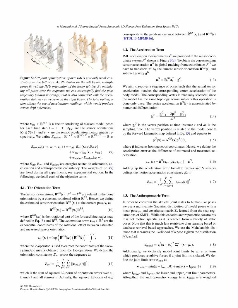
on a lower dimensional manifold. Acceleration measurements arenoisy and naive double integration to obtain position leads to un-bounded exponential drift, see Figure 4. Looking at a single framethe problem is ill-posed. However, looking at the full sequence,and using anthropometric constraints from a body model, makesthe problem much more constrained, see Figure 5. This motivatesus to formulate the following multi-frame objective function:
x∗1:T = arg minx1:T
Emotion(x1:T ,R1:T ,a1:T ), (8)
c© 2017 The Author(s)Computer Graphics Forum c© 2017 The Eurographics Association and John Wiley & Sons Ltd.
v. Marcard et al. / Sparse Inertial Poser:Automatic 3D Human Pose Estimation from Sparse IMUs
f ramesf rames
Figure 5: SIP joint optimization: sparse IMUs give only weak con-straints on the full pose. As illustrated on the left figure, multipleposes fit well the IMU orientation of the lower left leg. By optimiz-ing all poses over the sequence we can successfully find the posetrajectory (shown in orange) that is also consistent with the accel-eration data as can be seen on the right figure. The joint optimiza-tion allows the use of acceleration readings, which would producesevere drift otherwise.
where x1:T ∈ R75T is a vector consisting of stacked model posesfor each time step t = 1 . . .T . R1:T are the sensor orientationsRt ∈ SO(3) and a1:T are the sensor acceleration measurements re-spectively. We define Emotion : Rd×T ×R3N×T ×R3N×T → R as
Emotion(x1:T ,ω1:T ,a1:T ) =wori ·Eori(x1:T ,R1:T )
+wacc ·Eacc(x1:T ,a1:T )
+wanthro ·Eanthro(x1:T ),
(9)
where Eori, Eacc and Eanthro are energies related to orientation, ac-celeration and anthropometric consistency. The weights of Eq. (9)are fixed during all experiments, see experimental section. In thefollowing, we detail each of the objective terms.
4.1. The Orientation Term
The sensor orientations, RGS(t) : FS→ FG are related to the boneorientations by a constant rotational offset RBS. Hence, we definethe estimated sensor orientation RGS(xt) at the current pose xt as
RGS(xt) = RGB(xt)RBS, (10)
where RGB(xt) is the rotational part of the forward kinematics mapdefined in Eq. (5) and RBS. The orientation error eori ∈ R3 are theexponential coordinates of the rotational offset between estimatedand measured sensor orientation:
eori(xt) = log(
RGS(xt)(
RGS(t))−1
)∨, (11)
where the ∨-operator is used to extract the coordinates of the skew-symmetric matrix obtained from the log-operation. We define theorientation consistency Eori across the sequence as
Eori =1
T N
T
∑t=1
N
∑n=1||eori,n(t)||2, (12)
which is the sum of squared L2-norm of orientation errors over allframes t and all sensors n. Actually, the squared L2-norm of eori
corresponds to the geodesic distance between RGS(xt) and RGS(t)[HTDL13, MPMR16].
4.2. The Acceleration Term
IMU acceleration measurements aS are provided in the sensor coor-dinate system FS shown in Figure 3(a). To obtain the correspondingsensor acceleration aG in global tracking frame coordinates FG wehave to transform aS by the current sensor orientation RGS(t) andsubtract gravity gG
aGt = RGS
t aSt −gG. (13)
We aim to recover a sequence of poses such that the actual sensoracceleration matches the corresponding vertex acceleration of thebody model. The corresponding vertex is manually selected; sincethe model has the same topology across subjects this operation isdone only once. The vertex acceleration aG(t) is approximated bynumerical differentiation
aGt =
pGt−1−2pG
t +pGt+1
dt2 , (14)
where pGt is the vertex position at time instance t and dt is the
sampling time. The vertex position is related to the model pose xby the forward kinematic map defined in Eq. (5) and equates to
pG(x) = GGB(x)pB(0), (15)
where p indicates homogeneous coordinates. Hence, we define theacceleration error as the difference of estimated and measured ac-celeration
eacc(t) = aG(xt−1,xt ,xt+1)−aGt . (16)
Adding up the acceleration error for all T frames and N sensorsdefines the motion acceleration consistency Eacc:
Eacc =1
T N
T
∑t=1
N
∑n=1||eacc,n(t)||2. (17)
4.3. The Anthropometric Term
In order to constrain the skeletal joint states to human-like poseswe use a multivariate Gaussian distribution of model poses with amean pose µx and covariance matrix Σx learned from the scan reg-istrations of SMPL. While this encodes anthropometric constraintsit is not motion specific as it is learned from a variety of staticposes. Note that this is much less restrictive than learning based ordatabase retrieval based approaches. We use the Mahalanobis dis-tance that measures the likelihood of a pose x given the distributionN (µx,Σx):
dmahal =
√(x−µx)
TΣ−1x (x−µx). (18)
Additionally, we explicitly model joint limits by an error termwhich produces repulsive forces if a joint limit is violated. We de-fine the joint limit error elimit as
elimit = min(x− llower,0)+max(x− lupper,0) (19)
where llower and lupper are lower and upper joint limit parameters.Altogether, the anthropometric energy term Eantro is a weighted
c© 2017 The Author(s)Computer Graphics Forum c© 2017 The Eurographics Association and John Wiley & Sons Ltd.
v. Marcard et al. / Sparse Inertial Poser:Automatic 3D Human Pose Estimation from Sparse IMUs
(a) (b) (c) (d)
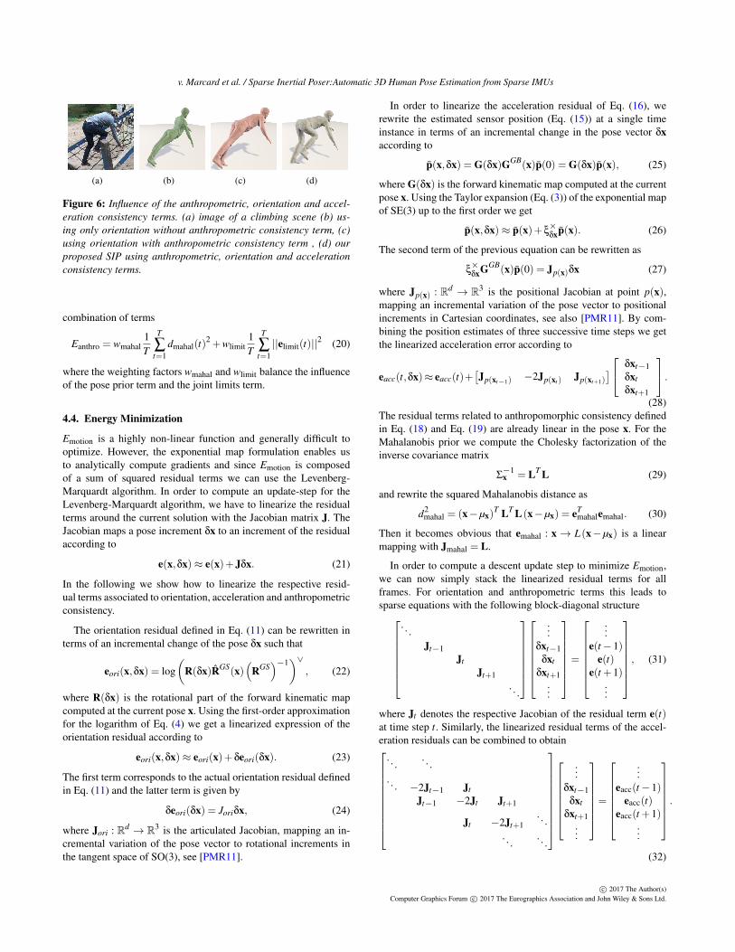
Figure 6: Influence of the anthropometric, orientation and accel-eration consistency terms. (a) image of a climbing scene (b) us-ing only orientation without anthropometric consistency term, (c)using orientation with anthropometric consistency term , (d) ourproposed SIP using anthropometric, orientation and accelerationconsistency terms.
combination of terms
Eanthro = wmahal1T
T
∑t=1
dmahal(t)2 +wlimit
1T
T
∑t=1||elimit(t)||2 (20)
where the weighting factors wmahal and wlimit balance the influenceof the pose prior term and the joint limits term.
4.4. Energy Minimization
Emotion is a highly non-linear function and generally difficult tooptimize. However, the exponential map formulation enables usto analytically compute gradients and since Emotion is composedof a sum of squared residual terms we can use the Levenberg-Marquardt algorithm. In order to compute an update-step for theLevenberg-Marquardt algorithm, we have to linearize the residualterms around the current solution with the Jacobian matrix J. TheJacobian maps a pose increment δx to an increment of the residualaccording to
e(x,δx)≈ e(x)+Jδx. (21)
In the following we show how to linearize the respective resid-ual terms associated to orientation, acceleration and anthropometricconsistency.
The orientation residual defined in Eq. (11) can be rewritten interms of an incremental change of the pose δx such that
eori(x,δx) = log(
R(δx)RGS(x)(
RGS)−1
)∨, (22)
where R(δx) is the rotational part of the forward kinematic mapcomputed at the current pose x. Using the first-order approximationfor the logarithm of Eq. (4) we get a linearized expression of theorientation residual according to
eori(x,δx)≈ eori(x)+δeori(δx). (23)
The first term corresponds to the actual orientation residual definedin Eq. (11) and the latter term is given by
δeori(δx) = Joriδx, (24)
where Jori : Rd → R3 is the articulated Jacobian, mapping an in-cremental variation of the pose vector to rotational increments inthe tangent space of SO(3), see [PMR11].
In order to linearize the acceleration residual of Eq. (16), werewrite the estimated sensor position (Eq. (15)) at a single timeinstance in terms of an incremental change in the pose vector δxaccording to
p(x,δx) = G(δx)GGB(x)p(0) = G(δx)p(x), (25)
where G(δx) is the forward kinematic map computed at the currentpose x. Using the Taylor expansion (Eq. (3)) of the exponential mapof SE(3) up to the first order we get
p(x,δx)≈ p(x)+ξ×δxp(x). (26)
The second term of the previous equation can be rewritten as
ξ×δxGGB(x)p(0) = Jp(x)δx (27)
where Jp(x) : Rd → R3 is the positional Jacobian at point p(x),mapping an incremental variation of the pose vector to positionalincrements in Cartesian coordinates, see also [PMR11]. By com-bining the position estimates of three successive time steps we getthe linearized acceleration error according to
eacc(t,δx)≈ eacc(t)+[Jp(xt−1) −2Jp(xt ) Jp(xt+1)
] δxt−1δxtδxt+1
.(28)
The residual terms related to anthropomorphic consistency definedin Eq. (18) and Eq. (19) are already linear in the pose x. For theMahalanobis prior we compute the Cholesky factorization of theinverse covariance matrix
Σ−1x = LT L (29)
and rewrite the squared Mahalanobis distance as
d2mahal = (x−µx)
T LT L(x−µx) = eTmahalemahal. (30)
Then it becomes obvious that emahal : x→ L (x−µx) is a linearmapping with Jmahal = L.
In order to compute a descent update step to minimize Emotion,we can now simply stack the linearized residual terms for allframes. For orientation and anthropometric terms this leads tosparse equations with the following block-diagonal structure
. . .Jt−1
JtJt+1
. . .
...δxt−1
δxtδxt+1
...
=
...e(t−1)
e(t)e(t +1)
...
, (31)
where Jt denotes the respective Jacobian of the residual term e(t)at time step t. Similarly, the linearized residual terms of the accel-eration residuals can be combined to obtain
. . .. . .
. . . −2Jt−1 JtJt−1 −2Jt Jt+1
Jt −2Jt+1. . .
. . .. . .
...δxt−1
δxtδxt+1
...
=
...eacc(t−1)
eacc(t)eacc(t +1)
...
.
(32)
c© 2017 The Author(s)Computer Graphics Forum c© 2017 The Eurographics Association and John Wiley & Sons Ltd.
v. Marcard et al. / Sparse Inertial Poser:Automatic 3D Human Pose Estimation from Sparse IMUs
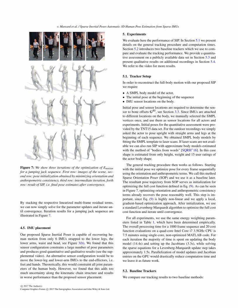
Figure 7: We show three iterations of the optimization of Emotionfor a jumping jack sequence. First row: images of the scene, sec-ond row: pose initialization obtained by minimizing orientation andanthropometric consistency, third row: intermediate iteration, forthrow: result of SIP, i.e. final pose estimates after convergence.
By stacking the respective linearized multi-frame residual terms,we can now simply solve for the parameter updates and iterate un-til convergence. Iteration results for a jumping jack sequence areillustrated in Figure 7.
4.5. IMU placement
Our proposed Sparse Inertial Poser is capable of recovering hu-man motion from only 6 IMUs strapped to the lower legs, thelower arms, waist and head, see Figure 3(b). We found that thissensor configuration constrains a large number of pose parametersand produces good quantitative and qualitative results (see the sup-plemental video). An alternative sensor configuration would be tomove the lower-leg and lower-arm IMUs to the end-effectors, i.e.feet and hands. Theoretically, this would constraint all joint param-eters of the human body. However, we found that this adds toomuch uncertainty along the kinematic chain structure and resultsin worse performance than the proposed sensor placement.
5. Experiments
We evaluate here the performance of SIP. In Section 5.1 we presentdetails on the general tracking procedure and computation times.Section 5.2 introduces two baseline trackers which we use to com-pare and evaluate the tracking performance. We provide a quantita-tive assessment on a publicly available data set in Section 5.3 andpresent qualitative results on additional recordings in Section 5.4.We refer to the video for more results.
5.1. Tracker Setup
In order to reconstruct the full-body motion with our proposed SIPwe require
• A SMPL body model of the actor,• The initial pose at the beginning of the sequence• IMU sensor locations on the body.
Initial pose and sensor locations are required to determine the sen-sor to bone offsets GBS, see Section 3.3. Since IMUs are attachedto different locations on the body, we manually selected the SMPLvertices once, and use them as sensor locations for all actors andexperiments. Initial poses for the quantitative assessment were pro-vided by the TNT15 data set. For the outdoor recordings we simplyasked the actor to pose upright with straight arms and legs at thebeginning of each sequence. We obtained SMPL body models byfitting the SMPL template to laser scans. If laser scans are not avail-able we can also run SIP with approximate body models estimatedwith the method of "bodies from words" [SQRH∗16]. In this caseshape is estimated from only height, weight and 15 user ratings ofthe actor body shape.
The general tracking procedure then works as follows. Startingwith the initial pose we optimize pose for every frame sequentiallyusing the orientation and anthropometric terms. We call this methodSparse Orientation Poser (SOP) and we use it as a baseline later.The resultant pose trajectory from SOP serves as initialization foroptimizing the full cost function defined in Eq. (9). As can be seenin Figure 7, optimizing orientation and anthropometric consistencyterms already recovers the pose reasonably well. This step is im-portant, since Eq. (9) is highly non-linear and we apply a local,gradient-based optimization approach. After initialization, we usea standard Levenberg-Marquardt algorithm to optimize the full costcost function and iterate until convergence.
For all experiments, we use the same energy weighting param-eters listed in Table 1, which have been determined empirically.The overall processing time for a 1000 frame sequence and 20 costfunction evaluations on a quad-core Intel Core i7 3.5GHz CPU is7.5 minutes using single-core, non-optimized MATLAB code. Foreach iteration the majority of time is spent on updating the bodymodel (14.4s) and setting up the Jacobians (3.3s), while solvingthe sparse equations for a Levenberg-Marquardt update step takesapproximately 1.5s. Parallelization of model updates and Jacobianentries on the GPU would drastically reduce computation time andwe leave it as future work.
5.2. Baseline Trackers
We compare our tracking results to two baseline methods:
c© 2017 The Author(s)Computer Graphics Forum c© 2017 The Eurographics Association and John Wiley & Sons Ltd.
v. Marcard et al. / Sparse Inertial Poser:Automatic 3D Human Pose Estimation from Sparse IMUs
wori wacc wanthro wmahal wlimits1 0.05 1 0.003 0.1
Table 1: Weighting parameters of Emotion, which have been usedfor all experiments.
0 200 400 600
0
20
40
0 200 400 600
0
0.1
0.2
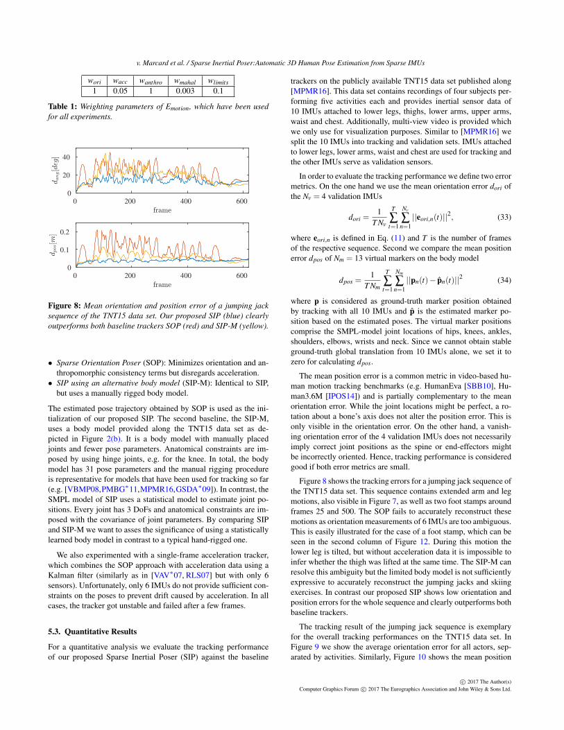
Figure 8: Mean orientation and position error of a jumping jacksequence of the TNT15 data set. Our proposed SIP (blue) clearlyoutperforms both baseline trackers SOP (red) and SIP-M (yellow).
• Sparse Orientation Poser (SOP): Minimizes orientation and an-thropomorphic consistency terms but disregards acceleration.• SIP using an alternative body model (SIP-M): Identical to SIP,
but uses a manually rigged body model.
The estimated pose trajectory obtained by SOP is used as the ini-tialization of our proposed SIP. The second baseline, the SIP-M,uses a body model provided along the TNT15 data set as de-picted in Figure 2(b). It is a body model with manually placedjoints and fewer pose parameters. Anatomical constraints are im-posed by using hinge joints, e.g. for the knee. In total, the bodymodel has 31 pose parameters and the manual rigging procedureis representative for models that have been used for tracking so far(e.g. [VBMP08,PMBG∗11,MPMR16,GSDA∗09]). In contrast, theSMPL model of SIP uses a statistical model to estimate joint po-sitions. Every joint has 3 DoFs and anatomical constraints are im-posed with the covariance of joint parameters. By comparing SIPand SIP-M we want to asses the significance of using a statisticallylearned body model in contrast to a typical hand-rigged one.
We also experimented with a single-frame acceleration tracker,which combines the SOP approach with acceleration data using aKalman filter (similarly as in [VAV∗07, RLS07] but with only 6sensors). Unfortunately, only 6 IMUs do not provide sufficient con-straints on the poses to prevent drift caused by acceleration. In allcases, the tracker got unstable and failed after a few frames.
5.3. Quantitative Results
For a quantitative analysis we evaluate the tracking performanceof our proposed Sparse Inertial Poser (SIP) against the baseline
trackers on the publicly available TNT15 data set published along[MPMR16]. This data set contains recordings of four subjects per-forming five activities each and provides inertial sensor data of10 IMUs attached to lower legs, thighs, lower arms, upper arms,waist and chest. Additionally, multi-view video is provided whichwe only use for visualization purposes. Similar to [MPMR16] wesplit the 10 IMUs into tracking and validation sets. IMUs attachedto lower legs, lower arms, waist and chest are used for tracking andthe other IMUs serve as validation sensors.
In order to evaluate the tracking performance we define two errormetrics. On the one hand we use the mean orientation error dori ofthe Nv = 4 validation IMUs
dori =1
T Nv
T
∑t=1
Nv
∑n=1||eori,n(t)||2, (33)
where eori,n is defined in Eq. (11) and T is the number of framesof the respective sequence. Second we compare the mean positionerror dpos of Nm = 13 virtual markers on the body model
dpos =1
T Nm
T
∑t=1
Nm
∑n=1||pn(t)− pn(t)||2 (34)
where p is considered as ground-truth marker position obtainedby tracking with all 10 IMUs and p is the estimated marker po-sition based on the estimated poses. The virtual marker positionscomprise the SMPL-model joint locations of hips, knees, ankles,shoulders, elbows, wrists and neck. Since we cannot obtain stableground-truth global translation from 10 IMUs alone, we set it tozero for calculating dpos.
The mean position error is a common metric in video-based hu-man motion tracking benchmarks (e.g. HumanEva [SBB10], Hu-man3.6M [IPOS14]) and is partially complementary to the meanorientation error. While the joint locations might be perfect, a ro-tation about a bone’s axis does not alter the position error. This isonly visible in the orientation error. On the other hand, a vanish-ing orientation error of the 4 validation IMUs does not necessarilyimply correct joint positions as the spine or end-effectors mightbe incorrectly oriented. Hence, tracking performance is consideredgood if both error metrics are small.
Figure 8 shows the tracking errors for a jumping jack sequence ofthe TNT15 data set. This sequence contains extended arm and legmotions, also visible in Figure 7, as well as two foot stamps aroundframes 25 and 500. The SOP fails to accurately reconstruct thesemotions as orientation measurements of 6 IMUs are too ambiguous.This is easily illustrated for the case of a foot stamp, which can beseen in the second column of Figure 12. During this motion thelower leg is tilted, but without acceleration data it is impossible toinfer whether the thigh was lifted at the same time. The SIP-M canresolve this ambiguity but the limited body model is not sufficientlyexpressive to accurately reconstruct the jumping jacks and skiingexercises. In contrast our proposed SIP shows low orientation andposition errors for the whole sequence and clearly outperforms bothbaseline trackers.
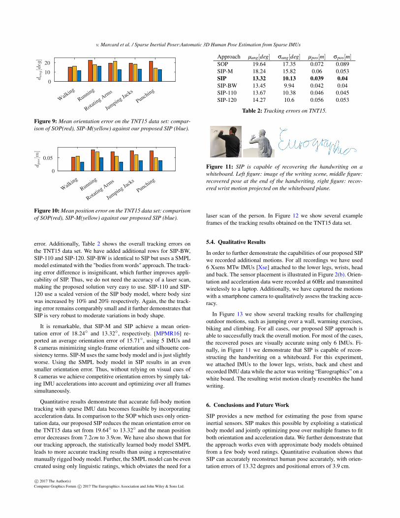
The tracking result of the jumping jack sequence is exemplaryfor the overall tracking performances on the TNT15 data set. InFigure 9 we show the average orientation error for all actors, sep-arated by activities. Similarly, Figure 10 shows the mean position
c© 2017 The Author(s)Computer Graphics Forum c© 2017 The Eurographics Association and John Wiley & Sons Ltd.
v. Marcard et al. / Sparse Inertial Poser:Automatic 3D Human Pose Estimation from Sparse IMUs
Walk
ing
Running
Rotating A
rms
Jumping Ja
cks
Punching
0
10
20
dang[d
eg]
Figure 9: Mean orientation error on the TNT15 data set: compar-ison of SOP(red), SIP-M(yellow) against our proposed SIP (blue).
Walk
ing
Running
Rotating A
rms
Jumping Ja
cks
Punching
0
0.05
dpos[m
]
Figure 10: Mean position error on the TNT15 data set: comparisonof SOP(red), SIP-M(yellow) against our proposed SIP (blue).
error. Additionally, Table 2 shows the overall tracking errors onthe TNT15 data set. We have added additional rows for SIP-BW,SIP-110 and SIP-120. SIP-BW is identical to SIP but uses a SMPLmodel estimated with the "bodies from words" approach. The track-ing error difference is insignificant, which further improves appli-cability of SIP. Thus, we do not need the accuracy of a laser scan,making the proposed solution very easy to use. SIP-110 and SIP-120 use a scaled version of the SIP body model, where body sizewas increased by 10% and 20% respectively. Again, the the track-ing error remains comparably small and it further demonstrates thatSIP is very robust to moderate variations in body shape.
It is remarkable, that SIP-M and SIP achieve a mean orien-tation error of 18.24◦ and 13.32◦, respectively. [MPMR16] re-ported an average orientation error of 15.71◦, using 5 IMUs and8 cameras minimizing single-frame orientation and silhouette con-sistency terms. SIP-M uses the same body model and is just slightlyworse. Using the SMPL body model in SIP results in an evensmaller orientation error. Thus, without relying on visual cues of8 cameras we achieve competitive orientation errors by simply tak-ing IMU accelerations into account and optimizing over all framessimultaneously.
Quantitative results demonstrate that accurate full-body motiontracking with sparse IMU data becomes feasible by incorporatingacceleration data. In comparison to the SOP which uses only orien-tation data, our proposed SIP reduces the mean orientation error onthe TNT15 data set from 19.64◦ to 13.32◦ and the mean positionerror decreases from 7.2cm to 3.9cm. We have also shown that forour tracking approach, the statistically learned body model SMPLleads to more accurate tracking results than using a representativemanually rigged body model. Further, the SMPL model can be evencreated using only linguistic ratings, which obviates the need for a
Approach µang[deg] σang[deg] µpos[m] σpos[m]
SOP 19.64 17.35 0.072 0.089SIP-M 18.24 15.82 0.06 0.053SIP 13.32 10.13 0.039 0.04SIP-BW 13.45 9.94 0.042 0.04SIP-110 13.67 10.38 0.046 0.045SIP-120 14.27 10.6 0.056 0.053
Table 2: Tracking errors on TNT15.
Figure 11: SIP is capable of recovering the handwriting on awhiteboard. Left figure: image of the writing scene, middle figure:recovered pose at the end of the handwriting, right figure: recov-ered wrist motion projected on the whiteboard plane.
laser scan of the person. In Figure 12 we show several exampleframes of the tracking results obtained on the TNT15 data set.
5.4. Qualitative Results
In order to further demonstrate the capabilities of our proposed SIPwe recorded additional motions. For all recordings we have used6 Xsens MTw IMUs [Xse] attached to the lower legs, wrists, headand back. The sensor placement is illustrated in Figure 2(b). Orien-tation and acceleration data were recorded at 60Hz and transmittedwirelessly to a laptop. Additionally, we have captured the motionswith a smartphone camera to qualitatively assess the tracking accu-racy.
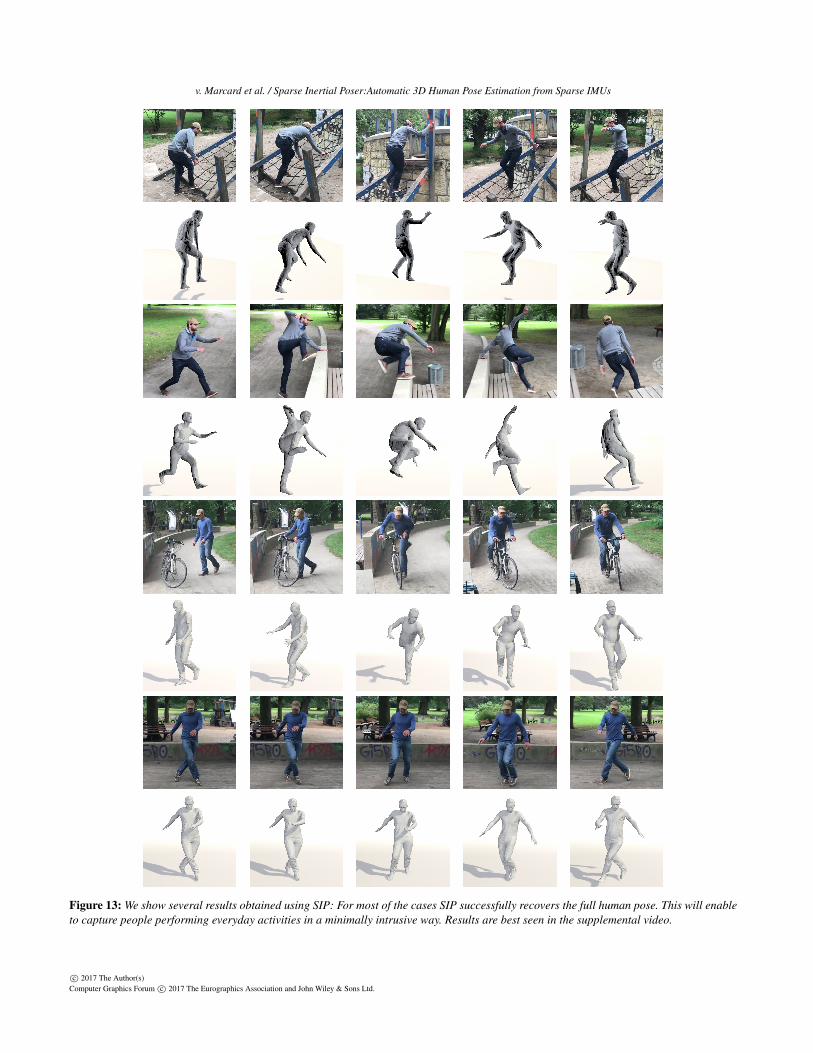
In Figure 13 we show several tracking results for challengingoutdoor motions, such as jumping over a wall, warming exercises,biking and climbing. For all cases, our proposed SIP approach isable to successfully track the overall motion. For most of the cases,the recovered poses are visually accurate using only 6 IMUs. Fi-nally, in Figure 11 we demonstrate that SIP is capable of recon-structing the handwriting on a whiteboard. For this experiment,we attached IMUs to the lower legs, wrists, back and chest andrecorded IMU data while the actor was writing “Eurographics” on awhite board. The resulting wrist motion clearly resembles the handwriting.
6. Conclusions and Future Work
SIP provides a new method for estimating the pose from sparseinertial sensors. SIP makes this possible by exploiting a statisticalbody model and jointly optimizing pose over multiple frames to fitboth orientation and acceleration data. We further demonstrate thatthe approach works even with approximate body models obtainedfrom a few body word ratings. Quantitative evaluation shows thatSIP can accurately reconstruct human pose accurately, with orien-tation errors of 13.32 degrees and positional errors of 3.9 cm.
c© 2017 The Author(s)Computer Graphics Forum c© 2017 The Eurographics Association and John Wiley & Sons Ltd.
v. Marcard et al. / Sparse Inertial Poser:Automatic 3D Human Pose Estimation from Sparse IMUs
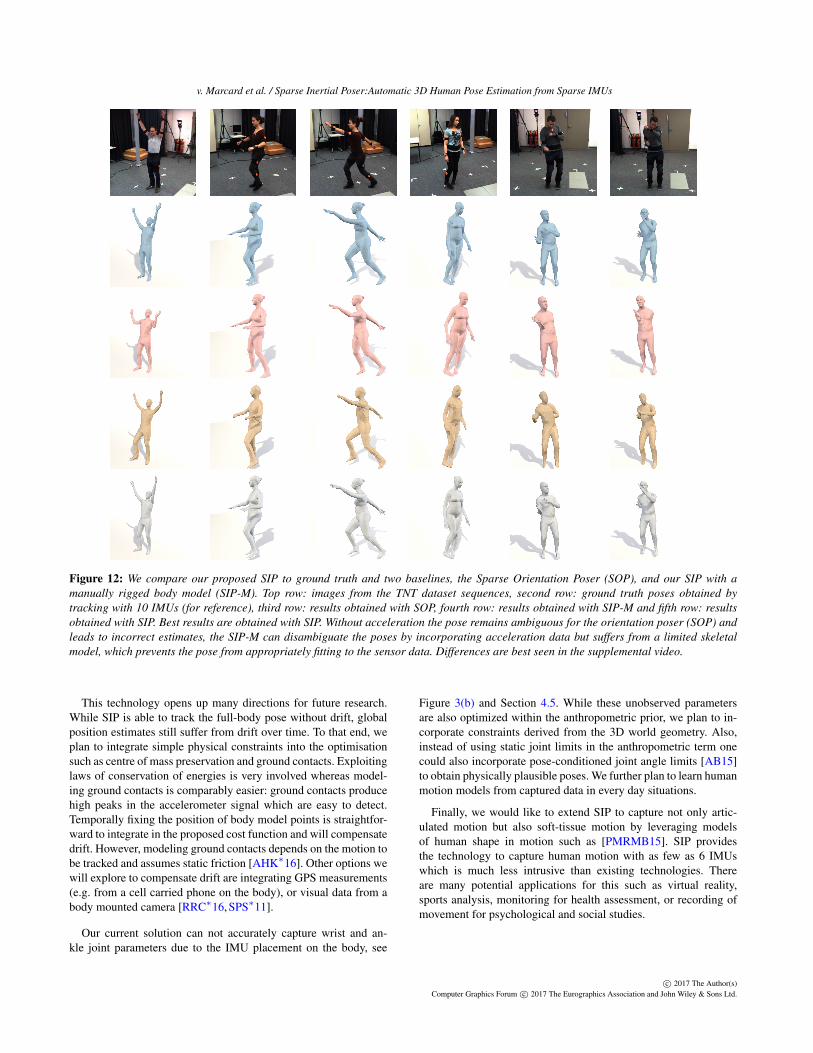
Figure 12: We compare our proposed SIP to ground truth and two baselines, the Sparse Orientation Poser (SOP), and our SIP with amanually rigged body model (SIP-M). Top row: images from the TNT dataset sequences, second row: ground truth poses obtained bytracking with 10 IMUs (for reference), third row: results obtained with SOP, fourth row: results obtained with SIP-M and fifth row: resultsobtained with SIP. Best results are obtained with SIP. Without acceleration the pose remains ambiguous for the orientation poser (SOP) andleads to incorrect estimates, the SIP-M can disambiguate the poses by incorporating acceleration data but suffers from a limited skeletalmodel, which prevents the pose from appropriately fitting to the sensor data. Differences are best seen in the supplemental video.
This technology opens up many directions for future research.While SIP is able to track the full-body pose without drift, globalposition estimates still suffer from drift over time. To that end, weplan to integrate simple physical constraints into the optimisationsuch as centre of mass preservation and ground contacts. Exploitinglaws of conservation of energies is very involved whereas model-ing ground contacts is comparably easier: ground contacts producehigh peaks in the accelerometer signal which are easy to detect.Temporally fixing the position of body model points is straightfor-ward to integrate in the proposed cost function and will compensatedrift. However, modeling ground contacts depends on the motion tobe tracked and assumes static friction [AHK∗16]. Other options wewill explore to compensate drift are integrating GPS measurements(e.g. from a cell carried phone on the body), or visual data from abody mounted camera [RRC∗16, SPS∗11].
Our current solution can not accurately capture wrist and an-kle joint parameters due to the IMU placement on the body, see
Figure 3(b) and Section 4.5. While these unobserved parametersare also optimized within the anthropometric prior, we plan to in-corporate constraints derived from the 3D world geometry. Also,instead of using static joint limits in the anthropometric term onecould also incorporate pose-conditioned joint angle limits [AB15]to obtain physically plausible poses. We further plan to learn humanmotion models from captured data in every day situations.
Finally, we would like to extend SIP to capture not only artic-ulated motion but also soft-tissue motion by leveraging modelsof human shape in motion such as [PMRMB15]. SIP providesthe technology to capture human motion with as few as 6 IMUswhich is much less intrusive than existing technologies. Thereare many potential applications for this such as virtual reality,sports analysis, monitoring for health assessment, or recording ofmovement for psychological and social studies.
c© 2017 The Author(s)Computer Graphics Forum c© 2017 The Eurographics Association and John Wiley & Sons Ltd.
v. Marcard et al. / Sparse Inertial Poser:Automatic 3D Human Pose Estimation from Sparse IMUs
Figure 13: We show several results obtained using SIP: For most of the cases SIP successfully recovers the full human pose. This will enableto capture people performing everyday activities in a minimally intrusive way. Results are best seen in the supplemental video.
c© 2017 The Author(s)Computer Graphics Forum c© 2017 The Eurographics Association and John Wiley & Sons Ltd.
v. Marcard et al. / Sparse Inertial Poser:Automatic 3D Human Pose Estimation from Sparse IMUs
Acknowledgments. This work is partly funded by the DFG-Project RO 2497/11-1. Authors gratefully acknowledge the sup-port. We thank Timo Bolkart, Laura Sevilla, Sergi Pujades, NaureenMahmood, Melanie Feldhofer and Osman Ulusoy for proofreading,Bastian Wandt and Aron Sommer for help with motion recordings,Talha Zaman for voice recordings, Alejandra Quiros for providingthe bodies from words and Senya Polikovsky, Andrea Keller andJorge Marquez for technical support.
References[AB15] AKHTER I., BLACK M. J.: Pose-conditioned joint angle limits
for 3D human pose reconstruction. In Proceedings of the IEEE Conf. onComputer Vision and Pattern Recognition (2015), pp. 1446–1455. 10
[AHK∗16] ANDREWS S., HUERTA I., KOMURA T., SIGAL L.,MITCHELL K.: Real-time physics-based motion capture with sparse sen-sors. In Proceedings of the 13th European Conference on Visual MediaProduction (CVMP 2016) (2016), ACM, p. 5. 3, 10
[BHM∗10] BAAK A., HELTEN T., MÜLLER M., PONS-MOLL G.,ROSENHAHN B., SEIDEL H.-P.: Analyzing and evaluating markerlessmotion tracking using inertial sensors. In European Conference on Com-puter Vision (2010), Springer, pp. 139–152. 4
[BKL∗16] BOGO F., KANAZAWA A., LASSNER C., GEHLER P.,ROMERO J., BLACK M. J.: Keep it SMPL: Automatic estimation of3D human pose and shape from a single image. In Computer Vision –ECCV 2016 (Oct. 2016), Lecture Notes in Computer Science, SpringerInternational Publishing. 2
[CH05] CHAI J., HODGINS J. K.: Performance animation from low-dimensional control signals. In ACM Transactions on Graphics (TOG)(2005), vol. 24, ACM, pp. 686–696. 2
[CMU] CMU motion capture database. http://mocap.cs.cmu.edu/. 1
[GSDA∗09] GALL J., STOLL C., DE AGUIAR E., THEOBALT C.,ROSENHAHN B., SEIDEL H.-P.: Motion capture using joint skeletontracking and surface estimation. In Computer Vision and Pattern Recog-nition, 2009. CVPR 2009 (2009), pp. 1746–1753. 8
[HKP∗16] HANNINK J., KAUTZ T., PASLUOSTA C., GASSMANN K.-G., KLUCKEN J., ESKOFIER B.: Sensor-based gait parameter extractionwith deep convolutional neural networks. IEEE Journal of Biomedicaland Health Informatics (2016). 2
[HMST13] HELTEN T., MULLER M., SEIDEL H.-P., THEOBALT C.:Real-time body tracking with one depth camera and inertial sensors. InProceedings of the IEEE International Conference on Computer Vision(2013), pp. 1105–1112. 3
[HTDL13] HARTLEY R., TRUMPF J., DAI Y., LI H.: Rotation averag-ing. International Journal of Computer Vision 103, 3 (2013), 267–305.5
[IPOS14] IONESCU C., PAPAVA D., OLARU V., SMINCHISESCU C.:Human3.6M: Large scale datasets and predictive methods for 3D humansensing in natural environments. IEEE Transactions on Pattern Analysisand Machine Intelligence 36, 7 (jul 2014), 1325–1339. 8
[LMR∗15] LOPER M., MAHMOOD N., ROMERO J., PONS-MOLL G.,BLACK M. J.: SMPL: A skinned multi-person linear model. ACM Trans.Graphics (Proc. SIGGRAPH Asia) 34, 6 (Oct. 2015), 248:1–248:16. 2,3
[LWC∗11] LIU H., WEI X., CHAI J., HA I., RHEE T.: Realtime humanmotion control with a small number of inertial sensors. In Symposiumon Interactive 3D Graphics and Games (2011), ACM, pp. 133–140. 2
[Mix] Mixamo. http://www.mixamo.com/. 1
[MLSS94] MURRAY R. M., LI Z., SASTRY S. S., SASTRY S. S.: Amathematical introduction to robotic manipulation. CRC press, 1994. 3
[Mov] House of moves. http://moves.com/. 1
[MPMR16] MARCARD T. V., PONS-MOLL G., ROSENHAHN B.: Hu-man pose estimation from video and IMUs. IEEE Transactions on Pat-tern Analysis and Machine Intelligence (TPAMI) 38, 8 (aug 2016), 1533–1547. 2, 3, 5, 8, 9
[PMBG∗11] PONS-MOLL G., BAAK A., GALL J., LEAL-TAIXE L.,MULLER M., SEIDEL H., ROSENHAHN B.: Outdoor human mo-tion capture using inverse kinematics and von mises-fisher sampling.pp. 1243–1250. 3, 8
[PMR09] PONS-MOLL G., ROSENHAHN B.: Ball joints for marker-lesshuman motion capture. In Applications of Computer Vision (WACV),2009 Workshop on (2009), IEEE, pp. 1–8. 3
[PMR11] PONS-MOLL G., ROSENHAHN B.: Model-Based Pose Estima-tion. Springer, 2011, ch. 9, pp. 139–170. 3, 6
[PMRMB15] PONS-MOLL G., ROMERO J., MAHMOOD N., BLACKM. J.: Dyna: A model of dynamic human shape in motion. ACM Trans-actions on Graphics, (Proc. SIGGRAPH) 34, 4 (2015), 120. 10
[RLS07] ROETENBERG D., LUINGE H., SLYCKE P.: Moven: Full 6dofhuman motion tracking using miniature inertial sensors. Xsen Technolo-gies, December (2007). 2, 3, 8
[RRC∗16] RHODIN H., RICHARDT C., CASAS D., INSAFUTDINOV E.,SHAFIEI M., SEIDEL H.-P., SCHIELE B., THEOBALT C.: EgoCap:egocentric marker-less motion capture with two fisheye cameras. 162.10
[SBB10] SIGAL L., BALAN A., BLACK M.: Humaneva: Synchronizedvideo and motion capture dataset and baseline algorithm for evaluationof articulated human motion. International Journal on Computer Vision(IJCV) 87, 1 (2010), 4–27. 8
[SH08] SLYPER R., HODGINS J.: Action capture with accelerometers.In ACM SIGGRAPH/Eurographics, SCA (2008). 2
[Sim] Simi Reality Motion Systems. http://www.simi.com. 1
[SMN09] SCHWARZ L., MATEUS D., NAVAB N.: Discriminative humanfull-body pose estimation from wearable inertial sensor data. Modellingthe Physiological Human (2009), 159–172. 2
[SPS∗11] SHIRATORI T., PARK H. S., SIGAL L., SHEIKH Y., HODGINSJ. K.: Motion capture from body-mounted cameras. In ACM Transac-tions on Graphics (TOG) (2011), vol. 30, ACM, p. 31. 10
[SQRH∗16] STREUBER S., QUIROS-RAMIREZ M. A., HILL M. Q.,HAHN C. A., ZUFFI S., O’TOOLE A., BLACK M. J.: Body Talk:Crowdshaping realistic 3D avatars with words. ACM Trans. Graph.(Proc. SIGGRAPH) 35, 4 (July 2016), 54:1–54:14. 7
[TBC∗16] TAYLOR J., BORDEAUX L., CASHMAN T., CORISH B., KE-SKIN C., SHARP T., SOTO E., SWEENEY D., VALENTIN J., LUFF B.,ET AL.: Efficient and precise interactive hand tracking through joint,continuous optimization of pose and correspondences. ACM Transac-tions on Graphics (TOG) 35, 4 (2016), 143. 2
[TST∗15] TAGLIASACCHI A., SCHRÖDER M., TKACH A., BOUAZIZS., BOTSCH M., PAULY M.: Robust articulated-ICP for real-time handtracking. In Computer Graphics Forum (2015), vol. 34, Wiley OnlineLibrary, pp. 101–114. 2
[TZK∗11] TAUTGES J., ZINKE A., KRÜGER B., BAUMANN J., WEBERA., HELTEN T., MÜLLER M., SEIDEL H.-P., EBERHARDT B.: Motionreconstruction using sparse accelerometer data. ACM Transactions onGraphics (TOG) 30, 3 (2011), 18. 2
[VAV∗07] VLASIC D., ADELSBERGER R., VANNUCCI G., BARNWELLJ., GROSS M., MATUSIK W., POPOVIC J.: Practical motion capture ineveryday surroundings. vol. 26, ACM, p. 35. 2, 3, 8
[VBMP08] VLASIC D., BARAN I., MATUSIK W., POPOVIC J.: Articu-lated mesh animation from multi-view silhouettes. In ACM Transactionson Graphics (TOG) (2008), vol. 27, ACM, p. 97. 8
[Vic] Vicon. http://www.vicon.com. 1
[Xse] XSens. https://www.xsens.com/products/. 2, 9
c© 2017 The Author(s)Computer Graphics Forum c© 2017 The Eurographics Association and John Wiley & Sons Ltd.