Embed Size (px)
DESCRIPTION
spark plugs info
Citation preview
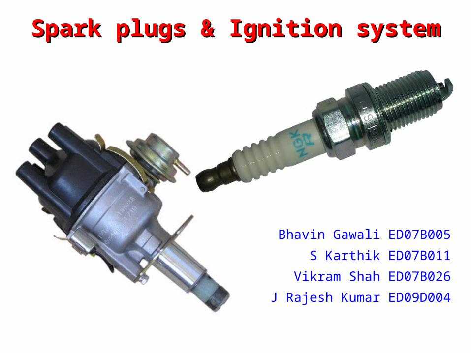
Spark plugs & Ignition systemSpark plugs & Ignition system
Bhavin Gawali ED07B005
S Karthik ED07B011Vikram Shah ED07B026
J Rajesh Kumar ED09D004
Structure of presentationStructure of presentation
• Ignition systems
• Spark plugs
Ignition systemIgnition system
FunctionFunction
• An ignition system is a system for igniting a fuel-air mixture at the right instant.
• It is best known in the field of internal combustion engines but also has other applications, e.g. in oil-fired and gas-fired boilers.
HistoryHistory
• The earliest internal combustion engines used a flame, or a heated tube, for ignition
• These were later replaced by systems using an electric spark. The instant of sparking is decided by the ignition system.
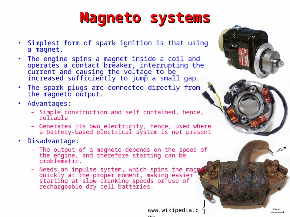
Magneto systemsMagneto systems• Simplest form of spark ignition is that using a magnet.• The engine spins a magnet inside a coil and operates a
contact breaker, interrupting the current and causing the voltage to be increased sufficiently to jump a small gap.
• The spark plugs are connected directly from the magneto output.
• Advantages:– Simple construction and self contained, hence, reliable– Generates its own electricity, hence, used where a battery-
based electrical system is not present• Disadvantage:
– The output of a magneto depends on the speed of the engine, and therefore starting can be problematic.
– Needs an impulse system, which spins the magnet quickly at the proper moment, making easier starting at slow cranking speeds or use of rechargeable dry cell batteries.
www.wikipedia.com
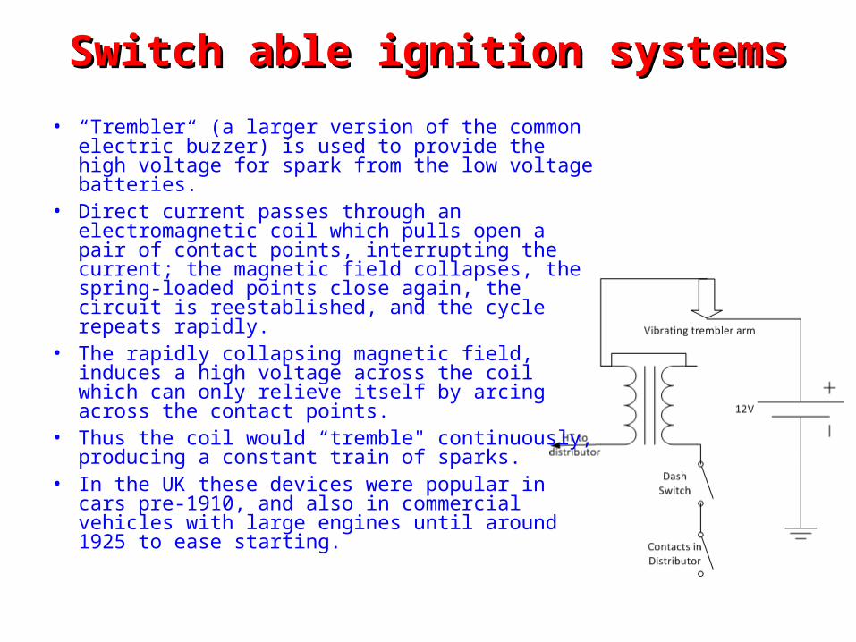
Switch able ignition systemsSwitch able ignition systems• “Trembler“ (a larger version of the common
electric buzzer) is used to provide the high voltage for spark from the low voltage batteries.
• Direct current passes through an electromagnetic coil which pulls open a pair of contact points, interrupting the current; the magnetic field collapses, the spring-loaded points close again, the circuit is reestablished, and the cycle repeats rapidly.
• The rapidly collapsing magnetic field, induces a high voltage across the coil which can only relieve itself by arcing across the contact points.
• Thus the coil would “tremble" continuously, producing a constant train of sparks.
• In the UK these devices were popular in cars pre-1910, and also in commercial vehicles with large engines until around 1925 to ease starting.
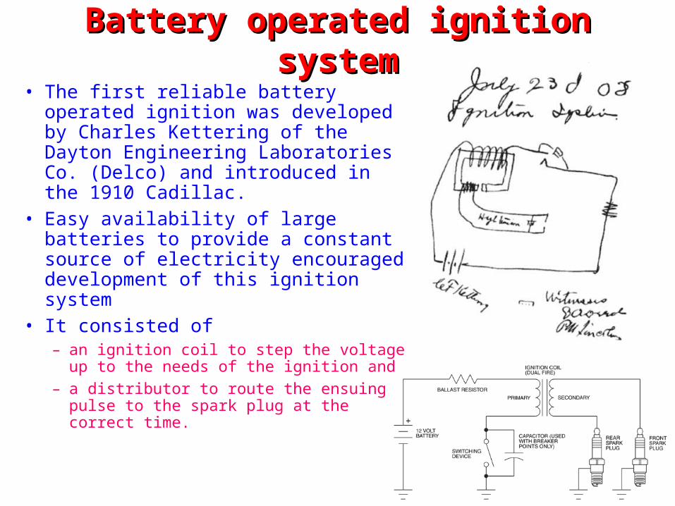
Battery operated ignition systemBattery operated ignition system• The first reliable battery operated
ignition was developed by Charles Kettering of the Dayton Engineering Laboratories Co. (Delco) and introduced in the 1910 Cadillac.
• Easy availability of large batteries to provide a constant source of electricity encouraged development of this ignition system
• It consisted of– an ignition coil to step the voltage up to
the needs of the ignition and– a distributor to route the ensuing pulse
to the spark plug at the correct time.
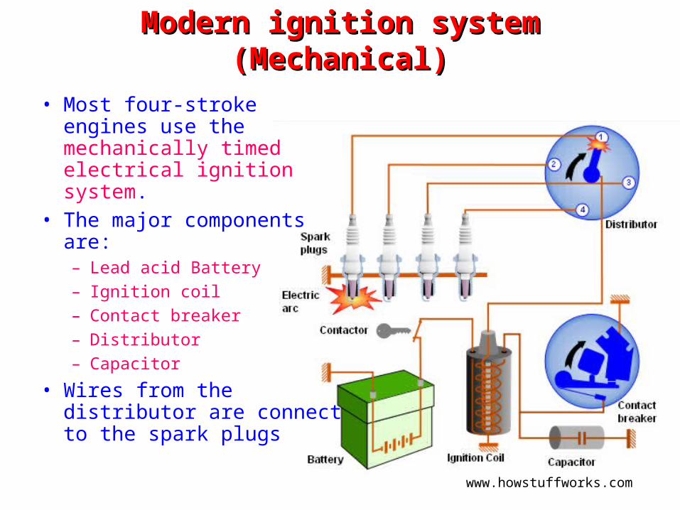
Modern ignition system (Mechanical)Modern ignition system (Mechanical)
• Most four-stroke engines use the mechanically timed electrical ignition system.
• The major components are:– Lead acid Battery– Ignition coil– Contact breaker– Distributor– Capacitor
• Wires from the distributor are connect to the spark plugs
www.howstuffworks.com
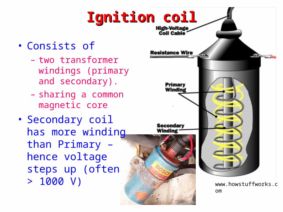
Ignition coilIgnition coil
• Consists of– two transformer
windings (primary and secondary).
– sharing a common magnetic core
• Secondary coil has more winding than Primary – hence voltage steps up (often > 1000 V)
www.howstuffworks.com
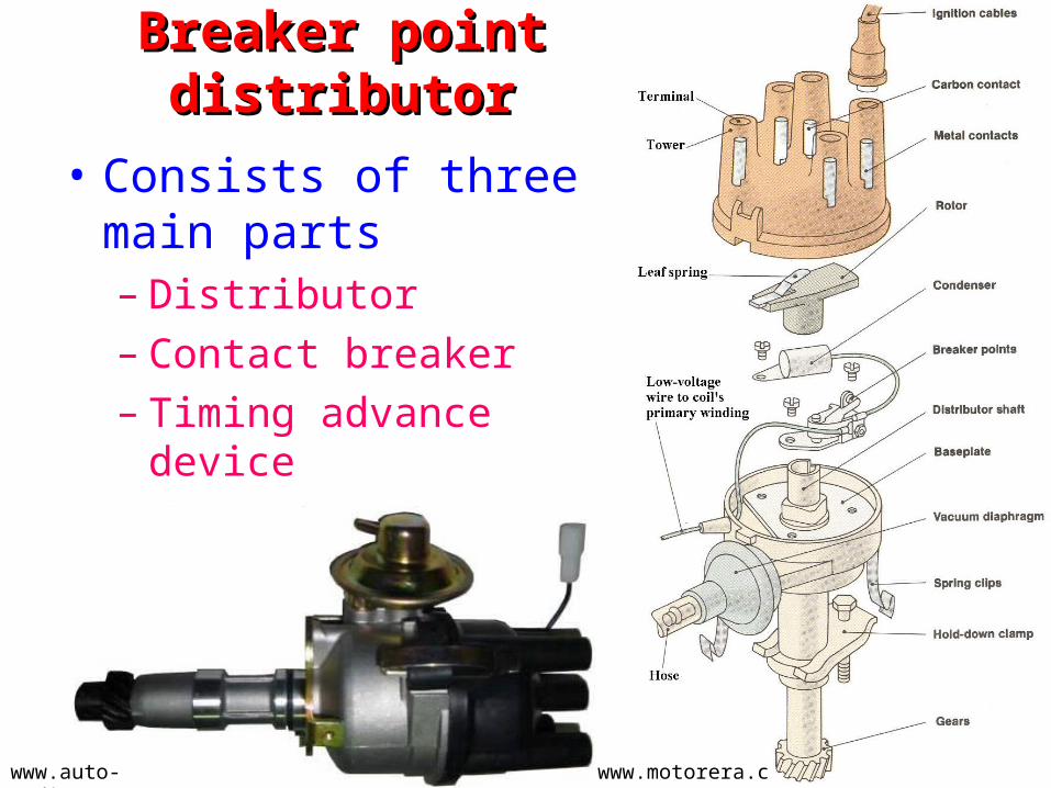
• Consists of three main parts– Distributor– Contact breaker– Timing advance device
• Driven by the engine
Breaker point distributorBreaker point distributor
www.motorera.comwww.auto-zodiac.com
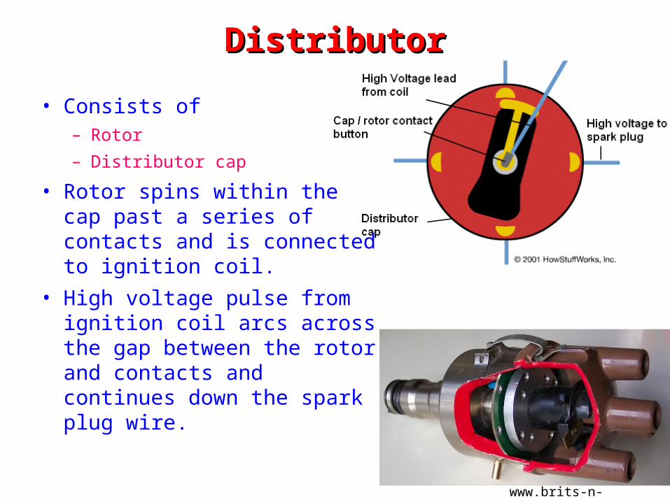
DistributorDistributor
• Consists of– Rotor– Distributor cap
• Rotor spins within the cap past a series of contacts and is connected to ignition coil.
• High voltage pulse from ignition coil arcs across the gap between the rotor and contacts and continues down the spark plug wire.
www.brits-n-pieces.com
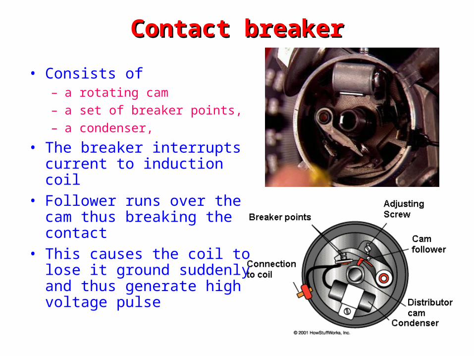
Contact breakerContact breaker
• Consists of– a rotating cam– a set of breaker points,– a condenser,
• The breaker interrupts current to induction coil
• Follower runs over the cam thus breaking the contact
• This causes the coil to lose it ground suddenly and thus generate high voltage pulse
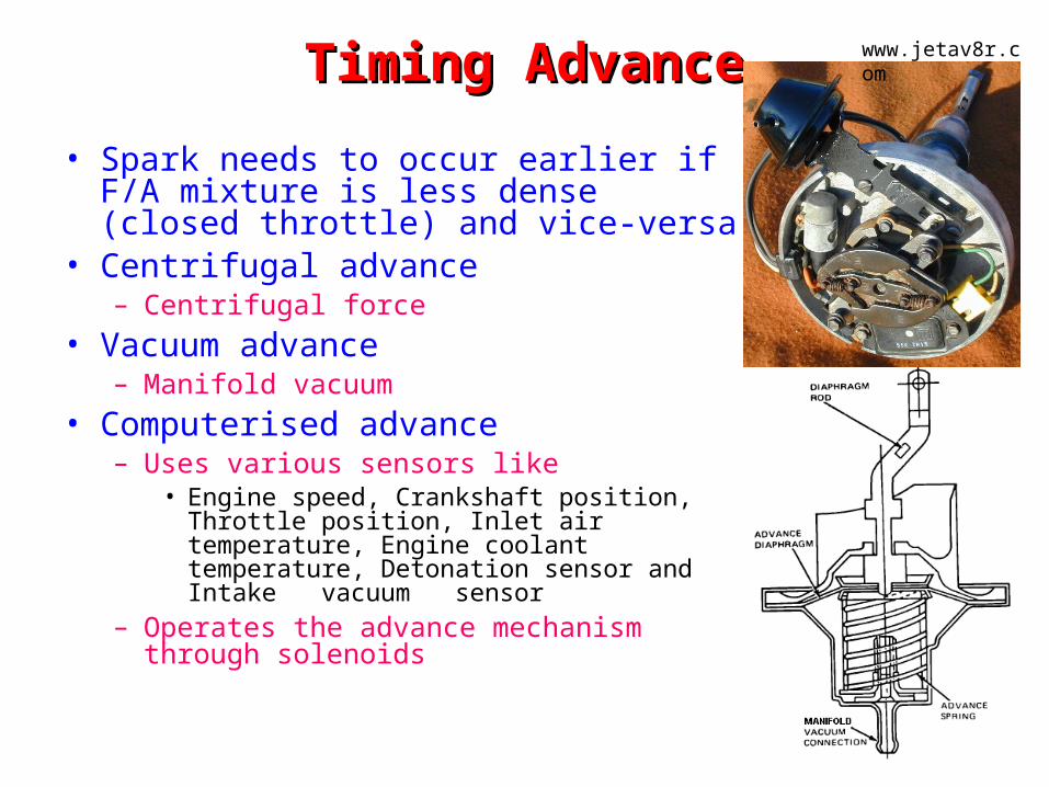
Timing AdvanceTiming Advance• Spark needs to occur earlier if F/A
mixture is less dense (closed throttle) and vice-versa
• Centrifugal advance– Centrifugal force
• Vacuum advance– Manifold vacuum
• Computerised advance– Uses various sensors like
• Engine speed, Crankshaft position, Throttle position, Inlet air temperature, Engine coolant temperature, Detonation sensor and Intake vacuum sensor
– Operates the advance mechanism through solenoids
www.jetav8r.com
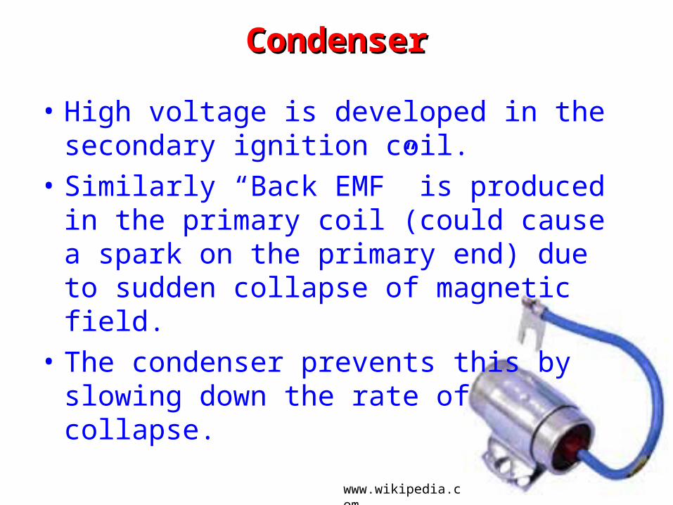
CondenserCondenser
• High voltage is developed in the secondary ignition coil.
• Similarly “Back EMF” is produced in the primary coil (could cause a spark on the primary end) due to sudden collapse of magnetic field.
• The condenser prevents this by slowing down the rate of collapse.
www.wikipedia.com
Disadvantage of the mechanical systemDisadvantage of the mechanical system
• Breaker contact points require regular replacement because– points are subject to mechanical wear where they ride
the cam to open and shut– oxidation and burning at the point contact surfaces
from the constant sparking.• Spark voltage is also dependent on contact
effectiveness, and poor sparking can lead to lower engine efficiency.
• Beyond average ignition current ~ 3A, service life reduces, thus limiting the power of the spark and ultimate engine speed.
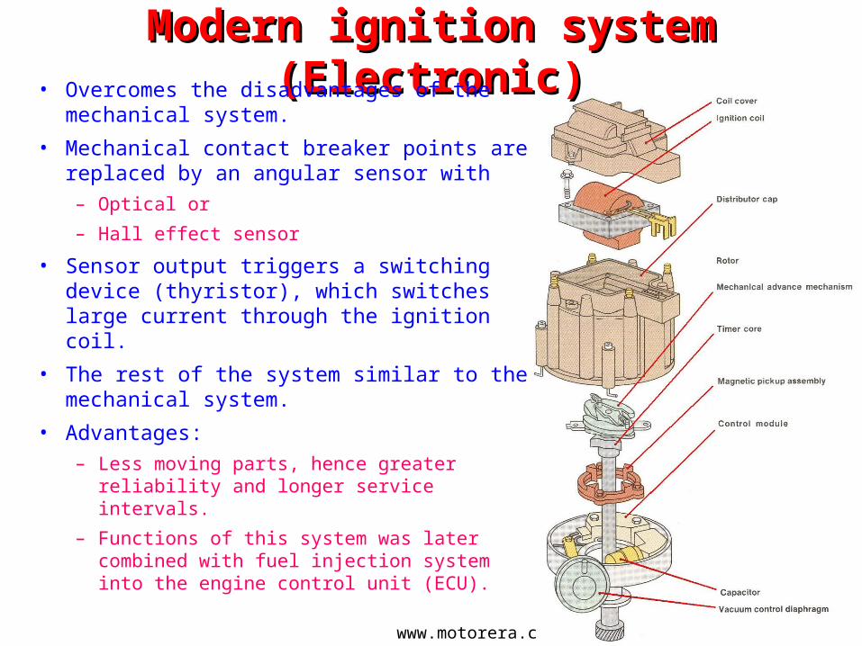
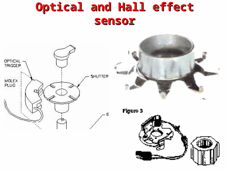
Modern ignition system (Electronic)Modern ignition system (Electronic)• Overcomes the disadvantages of the
mechanical system.• Mechanical contact breaker points are
replaced by an angular sensor with– Optical or– Hall effect sensor
• Sensor output triggers a switching device (thyristor), which switches large current through the ignition coil.
• The rest of the system similar to the mechanical system.
• Advantages:– Less moving parts, hence greater reliability
and longer service intervals.– Functions of this system was later combined
with fuel injection system into the engine control unit (ECU).
www.motorera.com
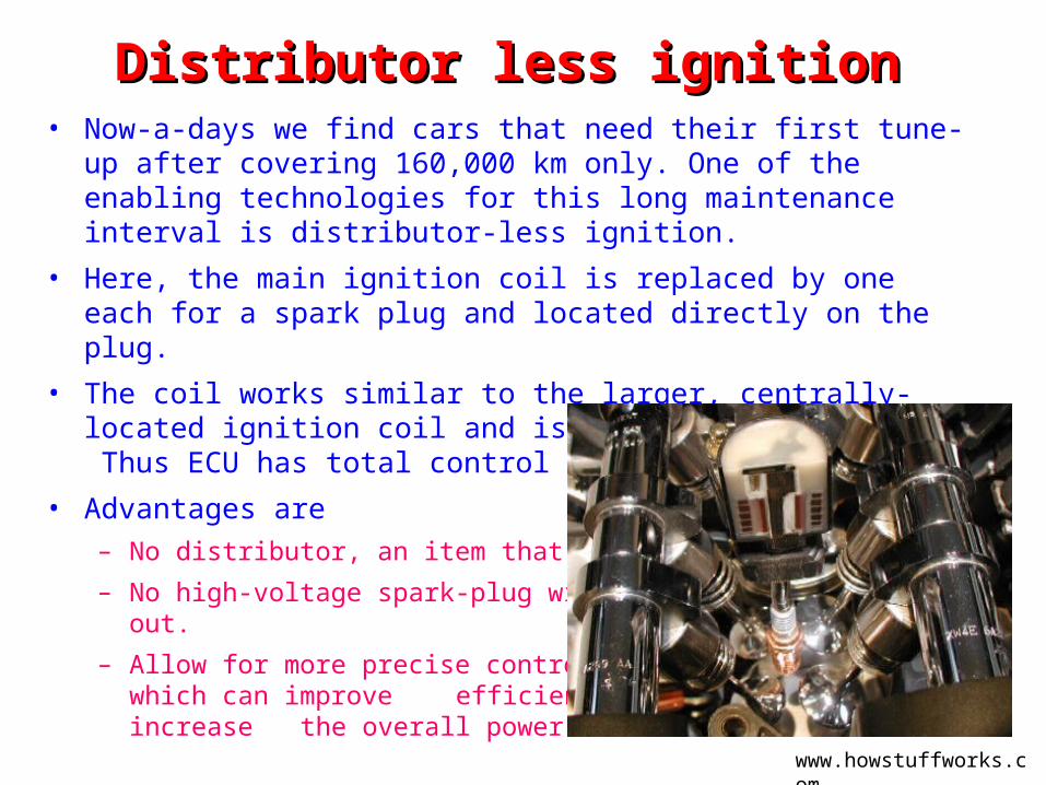
Distributor less ignition Distributor less ignition • Now-a-days we find cars that need their first tune-up after covering
160,000 km only. One of the enabling technologies for this long maintenance interval is distributor-less ignition.
• Here, the main ignition coil is replaced by one each for a spark plug and located directly on the plug.
• The coil works similar to the larger, centrally-located ignition coil and is controlled by the ECU. Thus ECU has total control over spark timing.
• Advantages are– No distributor, an item that eventually
wears out.– No high-voltage spark-plug wires,
which also wear out.– Allow for more precise control of the
spark timing, which can improve efficiency, emissions and increase
the overall power of a car. www.howstuffworks.com
Spark PlugsSpark Plugs
Spark plugsSpark plugs
• Used in SI engines• Function
– Starts the combustion process when the piston is at the TDC.
– Electricity converted in to spark by forcing electricity to arc across a gap, just like a bolt of lightning.
• Salient Features– Voltage at the spark plug can be anywhere from 40,000 to
100,000 volts.– Spark plugs also transfer heat away from the combustion
chamber.
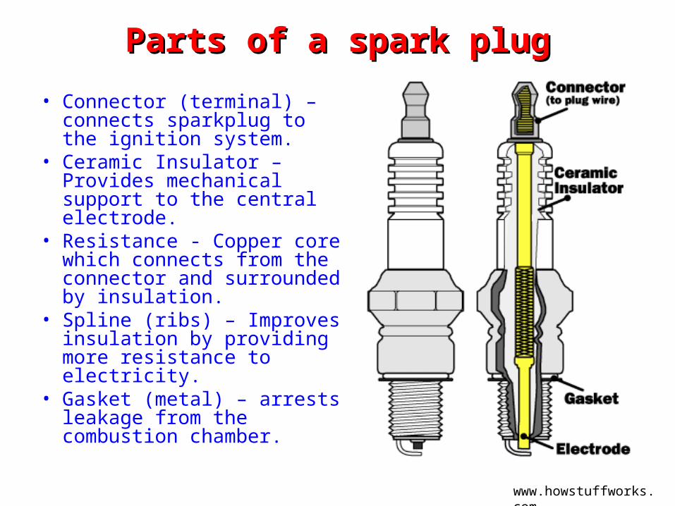
Parts of a spark plugParts of a spark plug• Connector (terminal) –
connects sparkplug to the ignition system.
• Ceramic Insulator – Provides mechanical support to the central electrode.
• Resistance - Copper core which connects from the connector and surrounded by insulation.
• Spline (ribs) – Improves insulation by providing more resistance to electricity.
• Gasket (metal) – arrests leakage from the combustion chamber.
www.howstuffworks.com
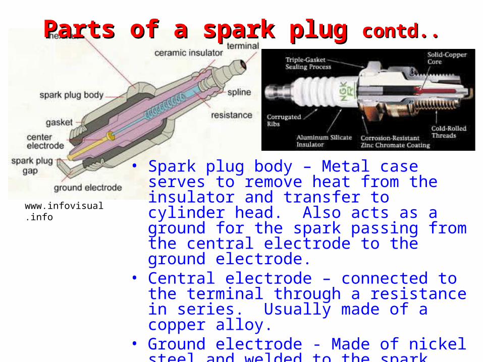
Parts of a spark plug Parts of a spark plug contd..contd..
• Spark plug body – Metal case serves to remove heat from the insulator and transfer to cylinder head. Also acts as a ground for the spark passing from the central electrode to the ground electrode.
• Central electrode – connected to the terminal through a resistance in series. Usually made of a copper alloy.
• Ground electrode - Made of nickel steel and welded to the spark plug body.
• Spark plug gap – Gap between the central electrode and ground electrode
www.infovisual.info
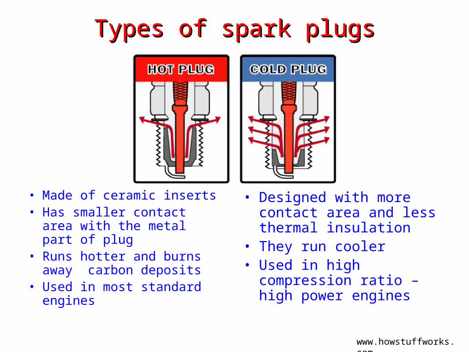
Types of spark plugsTypes of spark plugs
• Made of ceramic inserts• Has smaller contact area
with the metal part of plug• Runs hotter and burns away
carbon deposits• Used in most standard
engines
• Designed with more contact area and less thermal insulation
• They run cooler• Used in high compression
ratio – high power engines
www.howstuffworks.com
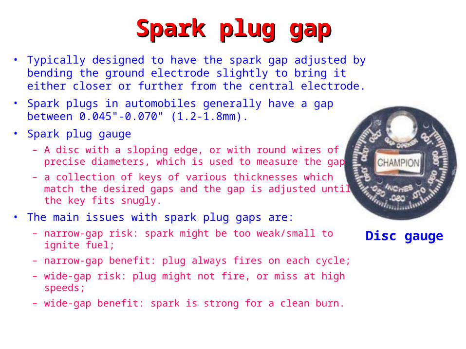
Spark plug gapSpark plug gap• Typically designed to have the spark gap adjusted by
bending the ground electrode slightly to bring it either closer or further from the central electrode.
• Spark plugs in automobiles generally have a gap between 0.045"-0.070" (1.2-1.8mm).
• Spark plug gauge– A disc with a sloping edge, or with round wires of precise
diameters, which is used to measure the gap– a collection of keys of various thicknesses which match the
desired gaps and the gap is adjusted until the key fits snugly.
• The main issues with spark plug gaps are:– narrow-gap risk: spark might be too weak/small to ignite fuel; – narrow-gap benefit: plug always fires on each cycle;– wide-gap risk: plug might not fire, or miss at high speeds;– wide-gap benefit: spark is strong for a clean burn.
Disc gauge
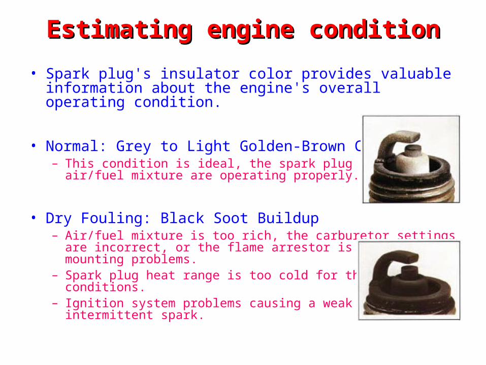
Estimating engine conditionEstimating engine condition• Spark plug's insulator color provides valuable information
about the engine's overall operating condition.
• Normal: Grey to Light Golden-Brown Color– This condition is ideal, the spark plug and engine
air/fuel mixture are operating properly.
• Dry Fouling: Black Soot Buildup – Air/fuel mixture is too rich, the carburetor settings
are incorrect, or the flame arrestor is dirty or has mounting problems.
– Spark plug heat range is too cold for the operating conditions.
– Ignition system problems causing a weak or intermittent spark.
Estimating engine condition Estimating engine condition contd..contd..
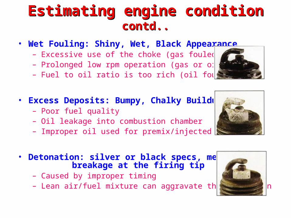
• Wet Fouling: Shiny, Wet, Black Appearance – Excessive use of the choke (gas fouled) – Prolonged low rpm operation (gas or oil fouled) – Fuel to oil ratio is too rich (oil fouled)
• Excess Deposits: Bumpy, Chalky Buildup – Poor fuel quality – Oil leakage into combustion chamber – Improper oil used for premix/injected
• Detonation: silver or black specs, melting or breakage at the firing tip– Caused by improper timing – Lean air/fuel mixture can aggravate this condition
Estimating engine condition Estimating engine condition contd..contd..
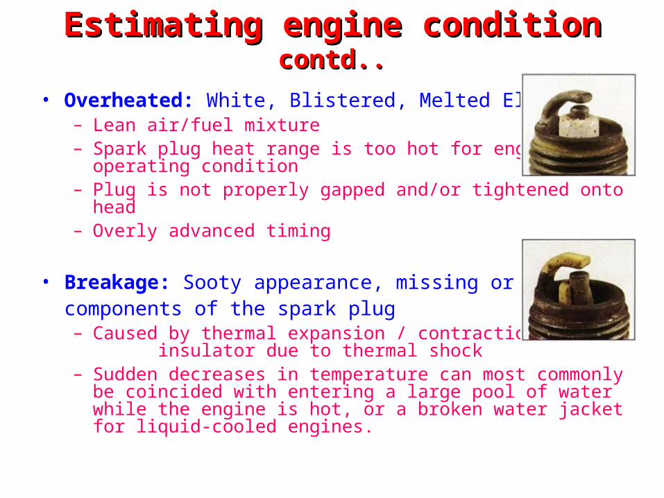
• Overheated: White, Blistered, Melted Electrode – Lean air/fuel mixture – Spark plug heat range is too hot for engine
operating condition– Plug is not properly gapped and/or tightened onto head – Overly advanced timing
• Breakage: Sooty appearance, missing or damage components of the spark plug– Caused by thermal expansion / contraction of the
insulator due to thermal shock– Sudden decreases in temperature can most commonly be
coincided with entering a large pool of water while the engine is hot, or a broken water jacket for liquid-cooled engines.
ReferencesReferences
• www.howcarswork.co.uk• www.rd.com• www.aa1car.com• www.auto-repair-help.com• www.infovisual.info• www.4x4review.com• www.howstuffworks.com• www.dieselpowermag.com• www.tpub.com • www.wikipedia.org• www.motorera.com

Thank youThank you

Optical and Hall effect sensorOptical and Hall effect sensor
Fuel Injection SystemFuel Injection System
• Used in both SI engines and CI engines
• In SI engines– mixture of fuel and air is injected into the
intake manifold• In CI engines
– pressurized fuel is sprayed into the cylinder.
Fuel Injection System in SI engineFuel Injection System in SI engine
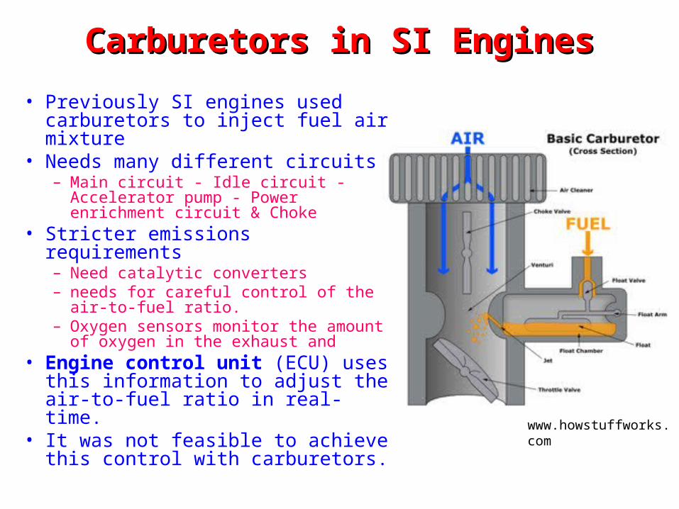
Carburetors in SI EnginesCarburetors in SI Engines• Previously SI engines used
carburetors to inject fuel air mixture• Needs many different circuits
– Main circuit - Idle circuit - Accelerator pump - Power enrichment circuit & Choke
• Stricter emissions requirements– Need catalytic converters– needs for careful control of the air-to-
fuel ratio.– Oxygen sensors monitor the amount of
oxygen in the exhaust and• Engine control unit (ECU) uses this
information to adjust the air-to-fuel ratio in real-time.
• It was not feasible to achieve this control with carburetors.
www.howstuffworks.com
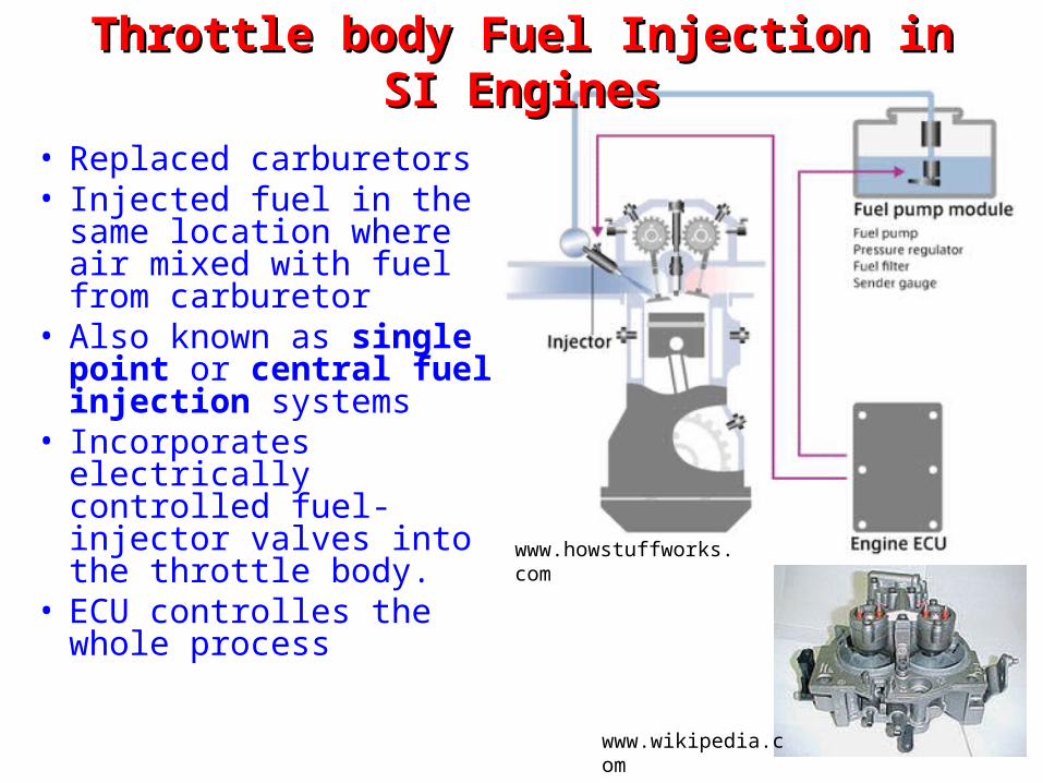
Throttle body Fuel Injection in SI EnginesThrottle body Fuel Injection in SI Engines
• Replaced carburetors• Injected fuel in the same
location where air mixed with fuel from carburetor
• Also known as single point or central fuel injection systems
• Incorporates electrically controlled fuel-injector valves into the throttle body.
• ECU controlles the whole process
www.howstuffworks.com
www.wikipedia.com
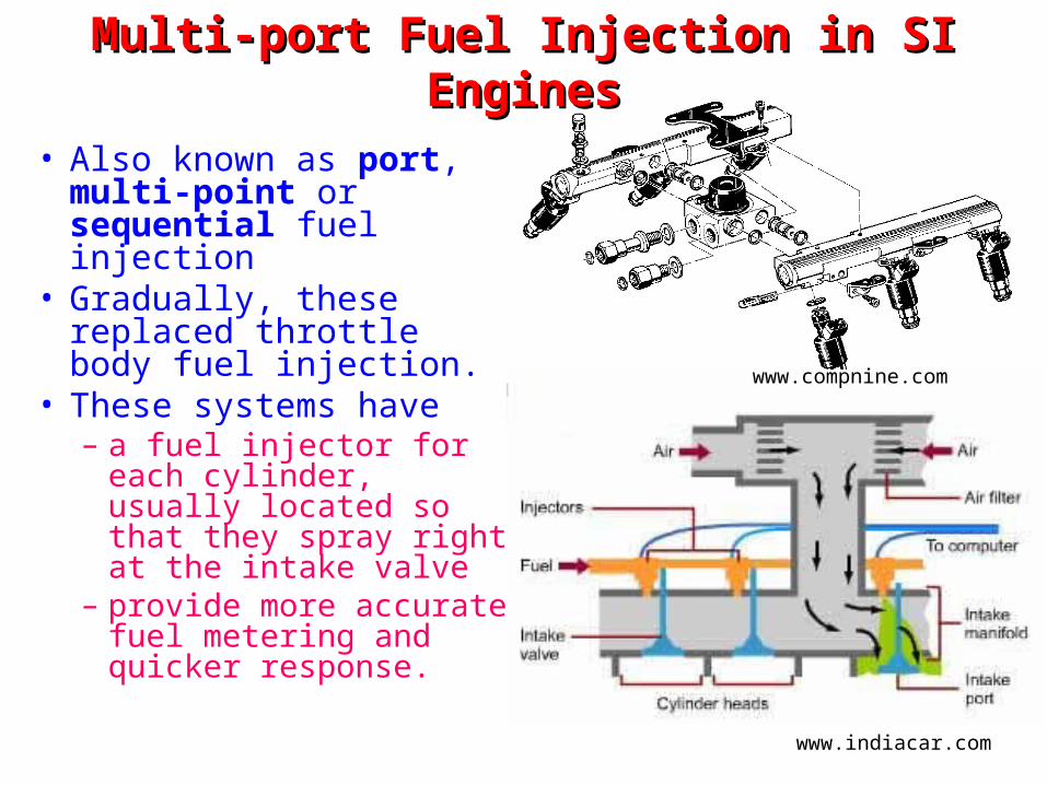
Multi-port Fuel Injection in SI EnginesMulti-port Fuel Injection in SI Engines
• Also known as port, multi-point or sequential fuel injection
• Gradually, these replaced throttle body fuel injection.
• These systems have– a fuel injector for each
cylinder, usually located so that they spray right at the intake valve
– provide more accurate fuel metering and quicker response.
www.indiacar.com
www.compnine.com
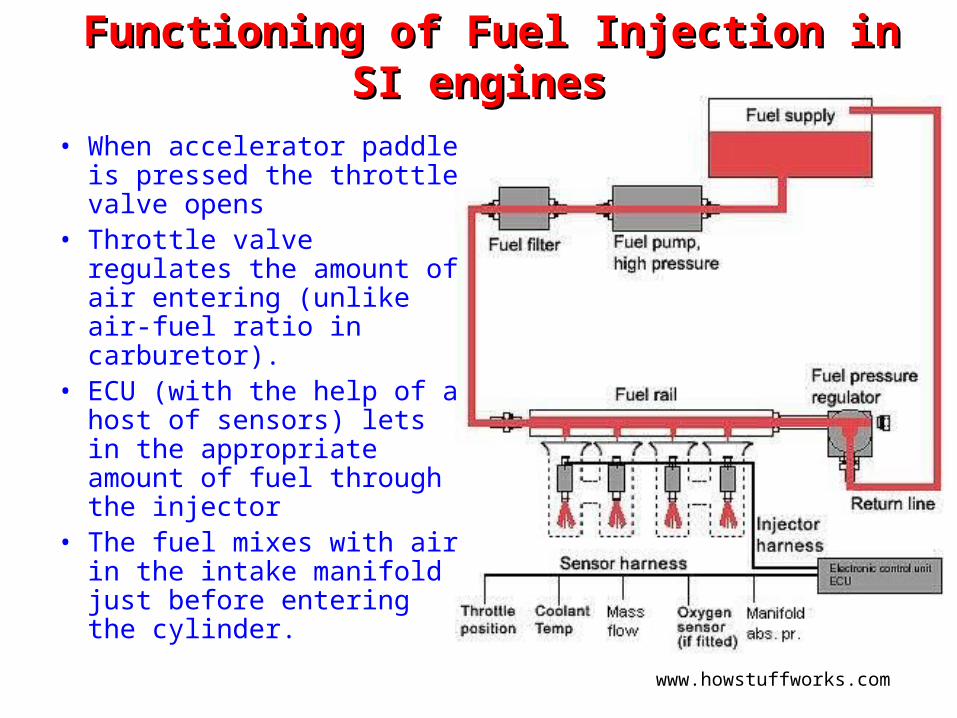
Functioning of Fuel Injection in SI enginesFunctioning of Fuel Injection in SI engines
• When accelerator paddle is pressed the throttle valve opens
• Throttle valve regulates the amount of air entering (unlike air-fuel ratio in carburetor).
• ECU (with the help of a host of sensors) lets in the appropriate amount of fuel through the injector
• The fuel mixes with air in the intake manifold just before entering the cylinder.
www.howstuffworks.com
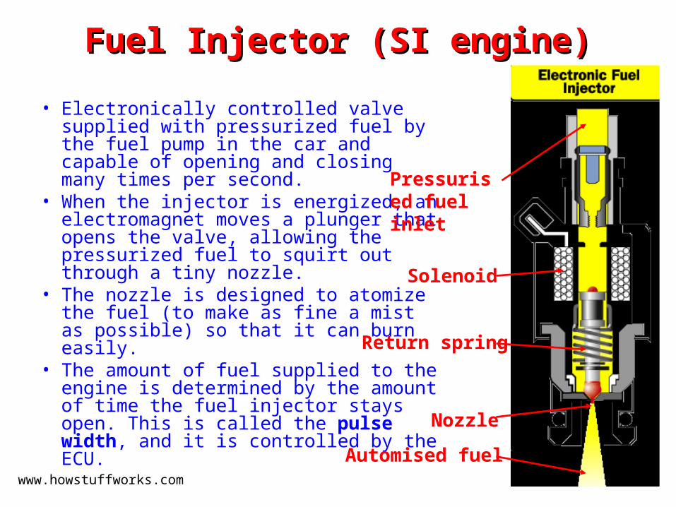
Fuel Injector (SI engine)Fuel Injector (SI engine)
• Electronically controlled valve supplied with pressurized fuel by the fuel pump in the car and capable of opening and closing many times per second.
• When the injector is energized, an electromagnet moves a plunger that opens the valve, allowing the pressurized fuel to squirt out through a tiny nozzle.
• The nozzle is designed to atomize the fuel (to make as fine a mist as possible) so that it can burn easily.
• The amount of fuel supplied to the engine is determined by the amount of time the fuel injector stays open. This is called the pulse width, and it is controlled by the ECU.
www.howstuffworks.com
Pressurised fuel inlet
Solenoid
Nozzle
Automised fuel
Return spring
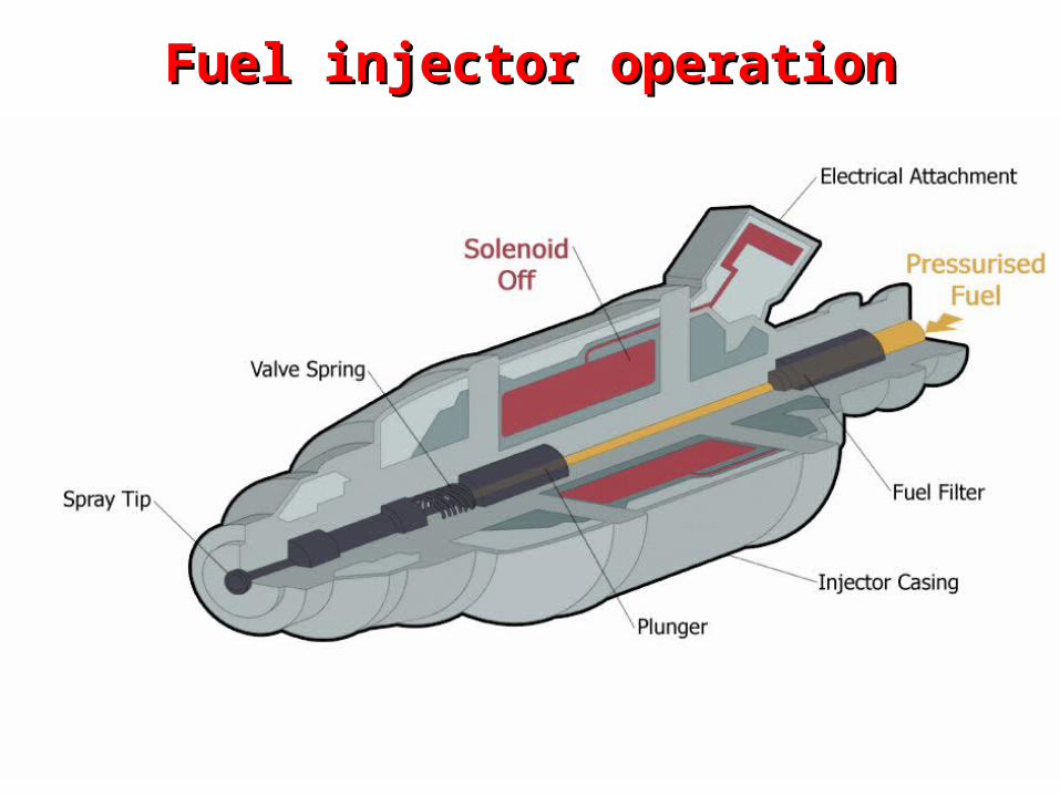
Fuel injector operationFuel injector operation

Fuel Injection System in CI engineFuel Injection System in CI engine

Fuel Injection in CI enginesFuel Injection in CI engines• First developed by Herbert
Akroyd Stuart• One major difference between a
CI and SI engine is in the fuel injection process.
• In CI engines fuel is injected directly into the combustion chamber.
• Consists of– Mechanically driven high pressure
injection pump with separate plungers for each cylinder
– The high pressure fuel from pump is deliver drectly into the combustion chamber by a fuel injector
• Pressurized fuel is sprayed towards the end of compression stroke
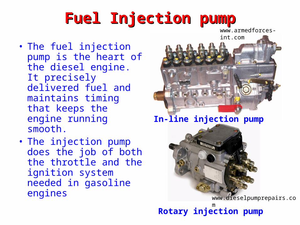
Fuel Injection pumpFuel Injection pump
• The fuel injection pump is the heart of the diesel engine. It precisely delivered fuel and maintains timing that keeps the engine running smooth.
• The injection pump does the job of both the throttle and the ignition system needed in gasoline engines
www.armedforces-int.com
In-line injection pump
Rotary injection pumpwww.dieselpumprepairs.com
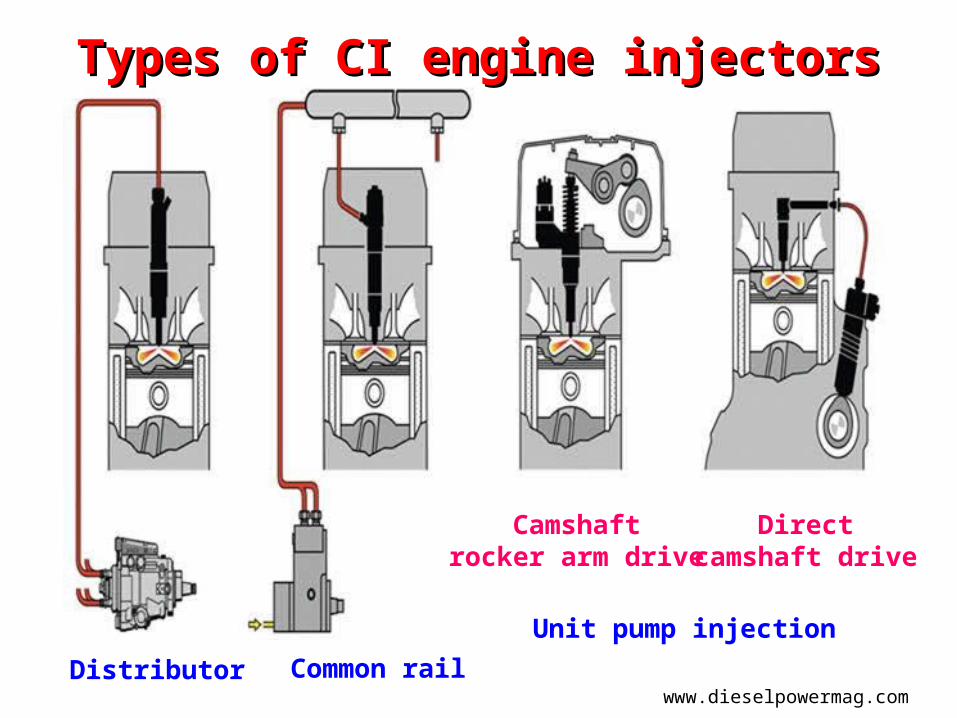
Types of CI engine injectorsTypes of CI engine injectors
www.dieselpowermag.comDistributor Common rail
Camshaftrocker arm drive
Directcamshaft drive
Unit pump injection
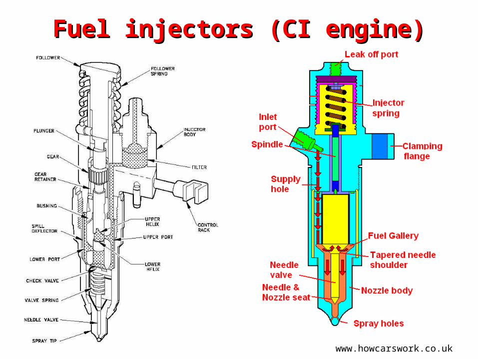
Fuel injectors (CI engine)Fuel injectors (CI engine)
www.howcarswork.co.uk