Embed Size (px)
Citation preview


SPARC EnterpriseTM T5120 andT5220 Servers Installation Guide
Part No. 875-4191-12July 2009, Revision A
Manual Code C120-E462-03EN

Copyright © 2009 Sun Microsystems, Inc., 4150 Network Circle, Santa Clara, California 95054, U.S.A. All rights reserved.
FUJITSU LIMITED provided technical input and review on portions of this material.
Sun Microsystems, Inc. and Fujitsu Limited each own or control intellectual property rights relating to products and technology described inthis document, and such products, technology and this document are protected by copyright laws, patents and other intellectual property lawsand international treaties. The intellectual property rights of Sun Microsystems, Inc. and Fujitsu Limited in such products, technology and thisdocument include, without limitation, one or more of the United States patents listed at http://www.sun.com/patents and one or moreadditional patents or patent applications in the United States or other countries.
This document and the product and technology to which it pertains are distributed under licenses restricting their use, copying, distribution,and decompilation. No part of such product or technology, or of this document, may be reproduced in any form by any means without priorwritten authorization of Fujitsu Limited and Sun Microsystems, Inc., and their applicable licensors, if any. The furnishing of this document toyou does not give you any rights or licenses, express or implied, with respect to the product or technology to which it pertains, and thisdocument does not contain or represent any commitment of any kind on the part of Fujitsu Limited or Sun Microsystems, Inc., or any affiliate ofeither of them.
This document and the product and technology described in this document may incorporate third-party intellectual property copyrighted byand/or licensed from suppliers to Fujitsu Limited and/or Sun Microsystems, Inc., including software and font technology.
Per the terms of the GPL or LGPL, a copy of the source code governed by the GPL or LGPL, as applicable, is available upon request by the EndUser. Please contact Fujitsu Limited or Sun Microsystems, Inc.
This distribution may include materials developed by third parties.
Parts of the product may be derived from Berkeley BSD systems, licensed from the University of California. UNIX is a registered trademark inthe U.S. and in other countries, exclusively licensed through X/Open Company, Ltd.
Sun™, Sun Microsystems™, the Sun logo©, Java™, Netra™, Solaris™, Sun StorageTek™, docs.sun.comSM, OpenBoot™, SunVTS™, Sun Fire™,SunSolveSM, CoolThreads™, and J2EE™, are trademarks or registered trademarks of Sun Microsystems, Inc. or its subsidiaries in the U.S. andother countries.
Fujitsu and the Fujitsu logo are registered trademarks of Fujitsu Limited.
All SPARC trademarks are used under license and are registered trademarks of SPARC International, Inc. in the U.S. and other countries.Products bearing SPARC trademarks are based upon architecture developed by Sun Microsystems, Inc.
SPARC64 is a trademark of SPARC International, Inc., used under license by Fujitsu Microelectronics, Inc. and Fujitsu Limited.
SSH is a registered trademark of SSH Communications Security in the United States and in certain other jurisdictions.
The OPEN LOOK and Sun™ Graphical User Interface was developed by Sun Microsystems, Inc. for its users and licensees. Sun acknowledgesthe pioneering efforts of Xerox in researching and developing the concept of visual or graphical user interfaces for the computer industry. Sunholds a non-exclusive license from Xerox to the Xerox Graphical User Interface, which license also covers Sun’s licensees who implement OPENLOOK GUIs and otherwise comply with Sun’s written license agreements.
United States Government Rights - Commercial use. U.S. Government users are subject to the standard government user license agreements ofSun Microsystems, Inc. and Fujitsu Limited and the applicable provisions of the FAR and its supplements.
Disclaimer: The only warranties granted by Fujitsu Limited, Sun Microsystems, Inc. or any affiliate of either of them in connection with thisdocument or any product or technology described herein are those expressly set forth in the license agreement pursuant to which the product ortechnology is provided.
EXCEPT AS EXPRESSLY SET FORTH IN SUCH AGREEMENT, FUJITSU LIMITED, SUN MICROSYSTEMS, INC. AND THEIR AFFILIATESMAKE NO REPRESENTATIONS OR WARRANTIES OF ANY KIND (EXPRESS OR IMPLIED) REGARDING SUCH PRODUCT ORTECHNOLOGY OR THIS DOCUMENT, WHICH ARE ALL PROVIDED AS IS, AND ALL EXPRESS OR IMPLIED CONDITIONS,REPRESENTATIONS AND WARRANTIES, INCLUDING WITHOUT LIMITATION ANY IMPLIED WARRANTY OF MERCHANTABILITY,FITNESS FOR A PARTICULAR PURPOSE OR NON-INFRINGEMENT, ARE DISCLAIMED, EXCEPT TO THE EXTENT THAT SUCHDISCLAIMERS ARE HELD TO BE LEGALLY INVALID.
Unless otherwise expressly set forth in such agreement, to the extent allowed by applicable law, in no event shall Fujitsu Limited, SunMicrosystems, Inc. or any of their affiliates have any liability to any third party under any legal theory for any loss of revenues or profits, loss ofuse or data, or business interruptions, or for any indirect, special, incidental or consequential damages, even if advised of the possibility of suchdamages.
DOCUMENTATION IS PROVIDED “AS IS” AND ALL EXPRESS OR IMPLIED CONDITIONS, REPRESENTATIONS AND WARRANTIES,INCLUDING ANY IMPLIED WARRANTY OF MERCHANTABILITY, FITNESS FOR A PARTICULAR PURPOSE OR NON-INFRINGEMENT,ARE DISCLAIMED, EXCEPT TO THE EXTENT THAT SUCH DISCLAIMERS ARE HELD TO BE LEGALLY INVALID.
PleaseRecycle

Copyright © 2009 Sun Microsystems, Inc., 4150 Network Circle, Santa Clara, California 95054, Etats-Unis. Tous droits réservés.
Entrée et revue tecnical fournies par FUJITSU LIMITED sur des parties de ce matériel.
Sun Microsystems, Inc. et Fujitsu Limited détiennent et contrôlent toutes deux des droits de propriété intellectuelle relatifs aux produits ettechnologies décrits dans ce document. De même, ces produits, technologies et ce document sont protégés par des lois sur le copyright, desbrevets, d’autres lois sur la propriété intellectuelle et des traités internationaux. Les droits de propriété intellectuelle de Sun Microsystems, Inc.et Fujitsu Limited concernant ces produits, ces technologies et ce document comprennent, sans que cette liste soit exhaustive, un ou plusieursdes brevets déposés aux États-Unis et indiqués à l’adresse http://www.sun.com/patents de même qu’un ou plusieurs brevets ou applicationsbrevetées supplémentaires aux États-Unis et dans d’autres pays.
Ce document, le produit et les technologies afférents sont exclusivement distribués avec des licences qui en restreignent l’utilisation, la copie, ladistribution et la décompilation. Aucune partie de ce produit, de ces technologies ou de ce document ne peut être reproduite sous quelqueforme que ce soit, par quelque moyen que ce soit, sans l’autorisation écrite préalable de Fujitsu Limited et de Sun Microsystems, Inc., et de leurséventuels bailleurs de licence. Ce document, bien qu’il vous ait été fourni, ne vous confère aucun droit et aucune licence, expresses ou tacites,concernant le produit ou la technologie auxquels il se rapporte. Par ailleurs, il ne contient ni ne représente aucun engagement, de quelque typeque ce soit, de la part de Fujitsu Limited ou de Sun Microsystems, Inc., ou des sociétés affiliées.
Ce document, et le produit et les technologies qu’il décrit, peuvent inclure des droits de propriété intellectuelle de parties tierces protégés parcopyright et/ou cédés sous licence par des fournisseurs à Fujitsu Limited et/ou Sun Microsystems, Inc., y compris des logiciels et destechnologies relatives aux polices de caractères.
Par limites du GPL ou du LGPL, une copie du code source régi par le GPL ou LGPL, comme applicable, est sur demande vers la fin utilsateurdisponible; veuillez contacter Fujitsu Limted ou Sun Microsystems, Inc.
Cette distribution peut comprendre des composants développés par des tierces parties.
Des parties de ce produit pourront être dérivées des systèmes Berkeley BSD licenciés par l’Université de Californie. UNIX est une marquedéposée aux Etats-Unis et dans d’autres pays et licenciée exclusivement par X/Open Company, Ltd.
Sun™, Sun Microsystems™, le logo Sun©, Java™, Netra™, Solaris™, Sun StorageTek™, docs.sun.comSM, OpenBoot™, SunVTS™, Sun Fire™,SunSolveSM, CoolThreads™, et J2EE™ sont des marques de fabrique ou des marques déposées de Sun Microsystems, Inc. , ou ses filiales auxEtats-Unis et dans d’autres pays.
Fujitsu et le logo Fujitsu sont des marques déposées de Fujitsu Limited.
Toutes les marques SPARC sont utilisées sous licence et sont des marques de fabrique ou des marques déposées de SPARC International, Inc.aux Etats-Unis et dans d’autres pays. Les produits portant les marques SPARC sont basés sur une architecture développée par SunMicrosystems, Inc.
SPARC64 est une marques déposée de SPARC International, Inc., utilisée sous le permis par Fujitsu Microelectronics, Inc. et Fujitsu Limited.
SSH est une marque déposée registre de SSH Communications Security aux Etats-Uniset dans certaines autres juridictions.
L’interface d’utilisation graphique OPEN LOOK et Sun™ a été développée par Sun Microsystems, Inc. pour ses utilisateurs et licenciés. Sunreconnaît les efforts de pionniers de Xerox pour la recherche et le développement du concept des interfaces d’utilisation visuelle ou graphiquepour l’industrie de l’informatique. Sun détient une license non exclusive de Xerox sur l’interface d’utilisation graphique Xerox, cette licencecouvrant également les licenciés de Sun qui mettent en place l’interface d’utilisation graphique OPEN LOOK et qui, en outre, se conforment auxlicences écrites de Sun.
Droits du gouvernement américain - logiciel commercial. Les utilisateurs du gouvernement américain sont soumis aux contrats de licencestandard de Sun Microsystems, Inc. et de Fujitsu Limited ainsi qu’aux clauses applicables stipulées dans le FAR et ses suppléments.
Avis de non-responsabilité: les seules garanties octroyées par Fujitsu Limited, Sun Microsystems, Inc. ou toute société affiliée de l’une ou l’autreentité en rapport avec ce document ou tout produit ou toute technologie décrit(e) dans les présentes correspondent aux garanties expressémentstipulées dans le contrat de licence régissant le produit ou la technologie fourni(e).
SAUF MENTION CONTRAIRE EXPRESSÉMENT STIPULÉE DANS CE CONTRAT, FUJITSU LIMITED, SUN MICROSYSTEMS, INC. ET LESSOCIÉTÉS AFFILIÉES REJETTENT TOUTE REPRÉSENTATION OU TOUTE GARANTIE, QUELLE QU’EN SOIT LA NATURE (EXPRESSEOU IMPLICITE) CONCERNANT CE PRODUIT, CETTE TECHNOLOGIE OU CE DOCUMENT, LESQUELS SONT FOURNIS EN L’ÉTAT. ENOUTRE, TOUTES LES CONDITIONS, REPRÉSENTATIONS ET GARANTIES EXPRESSES OU TACITES, Y COMPRIS NOTAMMENT TOUTEGARANTIE IMPLICITE RELATIVE À LA QUALITÉ MARCHANDE, À L’APTITUDE À UNE UTILISATION PARTICULIÈRE OU ÀL’ABSENCE DE CONTREFAÇON, SONT EXCLUES, DANS LA MESURE AUTORISÉE PAR LA LOI APPLICABLE.
Sauf mention contraire expressément stipulée dans ce contrat, dans la mesure autorisée par la loi applicable, en aucun cas Fujitsu Limited, SunMicrosystems, Inc. ou l’une de leurs filiales ne sauraient être tenues responsables envers une quelconque partie tierce, sous quelque théoriejuridique que ce soit, de tout manque à gagner ou de perte de profit, de problèmes d’utilisation ou de perte de données, ou d’interruptionsd’activités, ou de tout dommage indirect, spécial, secondaire ou consécutif, même si ces entités ont été préalablement informées d’une telleéventualité.
LA DOCUMENTATION EST FOURNIE “EN L’ETAT” ET TOUTES AUTRES CONDITIONS, DECLARATIONS ET GARANTIES EXPRESSESOU TACITES SONT FORMELLEMENT EXCLUES, DANS LA MESURE AUTORISEE PAR LA LOI APPLICABLE, Y COMPRIS NOTAMMENTTOUTE GARANTIE IMPLICITE RELATIVE A LA QUALITE MARCHANDE, A L’APTITUDE A UNE UTILISATION PARTICULIERE OU AL’ABSENCE DE CONTREFACON.


Contents
Preface ix
Preparing for Installation 1
Server Overview 1
Server Handling Precautions 3
Input Power Information and Precautions 3
Tools and Equipment Needed 4
Optional Component Installation 5
ESD Precautions 5
Installation Overview 6
Preparing for Installation 8
Installing the Hardware 8
Configuring the Service Processor 9
Configuring the Host Software 10
Cabling Notes for Both Servers 10
Port, Connector, and LED Locations for Both Servers 12
Slide Rail Assembly Notes for Both Servers 15
Cable Management Notes for Both Servers 18
Installing the SPARC Enterprise T5120 and T5220 Servers 19
Installing the Servers in a Rack 19
▼ To Install the Slide Rail Assemblies 20
▼ To Insert and Lock the Server in the Rack 26
v

Installing the Cable Management Arm for Both Servers 27
▼ To Install the Cable Management Arm 28
▼ To Verify the Operation of the Slide Rails and the CMA 32
Connecting the Server Cables for Both Servers 34
To Connect the Service Processor Serial Management Port 35
▼ To Connect the Service Processor Network Management Port 36
▼ To Connect the Ethernet Network Cables 38
▼ To Connect the AC Power Cable to the Server 38
Managing Cables With the CMA 39
▼ To Secure the Server Cables in the CMA 39
Dismounting the Servers 40
Powering On the System 43
Powering On the System for the First Time 43
ILOM System Console 43
ILOM Service Processor 44
▼ To Power On the System for the First Time 44
Enabling the Service Processor Network Management Port 49
Logging Into the Service Processor 51
▼ To Log Into the Service Processor Using the Serial Management Port51
▼ To Configure the Service Processor Network Management Port 52
▼ To Log Into the Service Processor Using the Network ManagementPort 55
Using the Service Processor for Common Operations 56
▼ To Power On the System 56
▼ To Connect to the System Console 58
▼ To Perform a Normal System Initialization 58
Devices in the OpenBoot Device Tree 60
Booting the Solaris Operating System 61
vi SPARC Enterprise T5120 and T5220 Servers Installation Guide • July 2009

▼ To Boot the Solaris Operating System 61
▼ To Avoid Booting the Solaris Operating System at Startup 63
▼ To Reset the System 63
▼ To Power Cycle the System 63
Verifying System Functionality 65
Updating the Firmware 67
flashupdate command 67
▼ To Update the Firmware 68
Selecting a Boot Device 71
Selecting a Boot Device 71
▼ To Select a Boot Device 72
Installing the Servers With the Express Rail Rackmounting Kit 73
Slide Rail Assembly Notes for the Express Rail Rackmounting Kit 74
Installing the Servers in a Rack With Express Rails 76
▼ To Install the Slide Rail Assemblies 76
▼ To Insert and Lock the Server in the Rack 81
Installing the Cable Management Arm 83
Dismounting the Server 84
Assembling and Installing DC Power Cables for the SPARC Enterprise T5120Server 85
Requirements for Servers With DC Input Power 85
DC Supply and Ground Conductor Requirements 86
Overcurrent Protection Requirements 87
Assembling and Installing the DC Input Power Cables 87
▼ To Assemble the DC Input Power Cables 88
▼ To Install the Strain Relief Housings 93
▼ Connecting the DC Input Power Cords to the Server 96
Contents vii

Assembling and Installing DC Power Cables for the SPARC Enterprise T5220Server 99
Requirements for Servers With DC Input Power 99
DC Supply and Ground Conductor Requirements 100
Overcurrent Protection Requirements 100
Assembling and Installing the DC Input Power Cables 101
▼ To Assemble the DC Input Power Cables 101
▼ To Connect the DC Input Power Cords 104
Index 107
viii SPARC Enterprise T5120 and T5220 Servers Installation Guide • July 2009

Preface
The SPARC Enterprise T5120 and T5220 Servers Installation Guide provides instructions,background information, and reference material to help you install SPARCEnterprise™ T5120 and T5220 servers.
The installation instructions in this document assume that a system administrator isexperienced with the Solaris™ Operating System (Solaris OS).
Note – All internal components except hard drives must be installed by qualifiedservice technicians only.
For Safe OperationThis manual contains important information regarding the use and handling of thisproduct. Read this manual thoroughly. Pay special attention to the section “Notes onSafety” on page xvi. Use the product according to the instructions and informationavailable in this manual. Keep this manual handy for further reference.
Fujitsu makes every effort to prevent users and bystanders from being injured orfrom suffering damage to their property. Use the product according to this manual.
ix

Structure and Contents of This ManualThis manual is organized as described below:
■ Preparing for Installation
Provides an installation overview for the servers.
■ Installing the SPARC Enterprise T5120 and T5220 Servers
Provides instructions for installing the servers into a rack.
■ Powering On the System
Provides instructions for configuring and powering on the servers.
■ Updating the Firmwaree
Provides instructions for updating the service processor firmware and the systemfirmware.
■ Selecting a Boot Device
Provides instructions for selecting a boot device.
■ Installing the Servers With the Express Rail Rackmounting Kit
Provides instructions for installing the servers into a rack with the Express railrackmounting kit.
■ Assembling and Installing DC Power Cables for the SPARC Enterprise T5120Server
Provides instructions for assembling and installing DC power cables on SPARCEnterprise T5120 servers with DC input power.
■ Assembling and Installing DC Power Cables for the SPARC Enterprise T5220Server
Provides instructions for assembling and installing DC power cables on SPARCEnterprise T5220 servers with DC input power.
Related DocumentationThe latest versions of all the SPARC Enterprise Series manuals are available at thefollowing Web sites:
Global Site
x SPARC Enterprise T5120 and T5220 Servers Installation Guide • July 2009

(http://www.fujitsu.com/sparcenterprise/manual/)
Japanese Site
(http://primeserver.fujitsu.com/sparcenterprise/manual/)
Title Description Manual Code
SPARC Enterprise T5120 ServerGetting Started Guide
Minimum steps to power on and boot theserver for the first time
C120-E518
SPARC Enterprise T5120 ServerGetting Started Guide For ModelsThat Run on DC Input Power
Minimum steps to power on and boot theserver that run on DC input power for thefirst time
C120-E552
SPARC Enterprise T5220 ServerGetting Started Guide
Minimum steps to power on and boot theserver for the first time
C120-E519
SPARC Enterprise T5220 ServerGetting Started Guide For ModelsThat Run on DC Input Power
Minimum steps to power on and boot theserver that run on DC input power for thefirst time
C120-E553
SPARC Enterprise T5120 andT5220 Servers Product Notes
Information about the latest productupdates and issues
C120-E458
Important Safety Information forHardware Systems
Safety information that is common to allSPARC Enterprise series servers
C120-E391
SPARC Enterprise T5120 andT5220 Servers Safety andCompliance Guide
Safety and compliance information that isspecific to the servers
C120-E461
SPARC Enterprise/PRIMEQUEST CommonInstallation Planning Manual
Requirements and concepts of installationand facility planning for the setup ofSPARC Enterprise and PRIMEQUEST
C120-H007
SPARC Enterprise T5120 andT5220 Servers Site PlanningGuide
Server specifications for site planning C120-H027
SPARC Enterprise T5120 andT5220 Servers Overview Guide
Product features C120-E460
SPARC Enterprise T5120 andT5220 Servers Installation Guide
Detailed rackmounting, cabling, power on,and configuring information
C120-E462
SPARC Enterprise T5120 andT5220 Servers Service Manual
How to run diagnostics to troubleshoot theserver, and how to remove and replaceparts in the server
C120-E463
SPARC Enterprise T5120 andT5220 Servers AdministrationGuide
How to perform administrative tasks thatare specific to the servers
C120-E464
Preface xi

Note – Product Notes are available on the website only. Please check for the recentupdate on your product.
Integrated Lights Out Manager2.0 User’s Guide
Information that is common to allplatforms managed by Integrated LightsOut Manager (ILOM) 2.0
C120-E474
Integrated Lights Out Manager2.0 Supplement for SPARCEnterprise T5120 and T5220Servers
How to use the ILOM 2.0 software on theservers
C120-E465
Integrated Lights Out Manager(ILOM) 3.0 Concepts Guide
Information that describes ILOM 3.0features and functionality
C120-E573
Integrated Lights Out Manager(ILOM) 3.0 Getting Started Guide
Information and procedures for networkconnection, logging in to ILOM 3.0 for thefirst time, and configuring a user accountor a directory service
C120-E576
Integrated Lights Out Manager(ILOM) 3.0 Web InterfaceProcedures Guide
Information and procedures for accessingILOM 3.0 functions using the ILOM webinterface
C120-E574
Integrated Lights Out Manager(ILOM) 3.0 CLI Procedures Guide
Information and procedures for accessingILOM 3.0 functions using the ILOM CLI
C120-E575
Integrated Lights Out Manager(ILOM) 3.0 SNMP and IPMIProcedures Guide
Information and procedures for accessingILOM 3.0 functions using SNMP or IPMImanagement hosts
C120-E579
Integrated Lights Out Manager(ILOM) 3.x Feature Updates andRelease Notes
Enhancements that have been made toILOM firmware since the ILOM 3.0 release
C120-E600
Integrated Lights Out Manager(ILOM) 3.0 Supplement forSPARC Enterprise T5120 andT5220 Servers
How to use the ILOM 3.0 software on theservers
C120-E577
External I/O Expansion UnitInstallation and Service Manual
Procedures for installing the External I/OExpansion Unit on the SPARC EnterpriseT5120/T5140/T5220/T5240/T5440 servers
C120-E543
External I/O Expansion UnitProduct Notes
Important and late-breaking informationabout the External I/O Expansion Unit
C120-E544
Title Description Manual Code
xii SPARC Enterprise T5120 and T5220 Servers Installation Guide • July 2009

UNIX CommandsThis document might not contain information on basic UNIX® commands andprocedures such as shutting down the system, booting the system, and configuringdevices. Refer to the following for this information:
■ Software documentation that you received with your system
■ Solaris™ Operating System documentation, which is at
(http://docs.sun.com)
Text Conventions
* The settings on your browser might differ from these settings.
Typeface* Meaning Examples
AaBbCc123 The names of commands, files,and directories; on-screencomputer output
Edit your .login file.Use ls -a to list all files.% You have mail.
AaBbCc123 What you type, whencontrasted with on-screencomputer output
% su
Password:
AaBbCc123 Book titles, new words or terms,words to be emphasized.Replace command-linevariables with real names orvalues.
Read Chapter 6 in the User’s Guide.These are called class options.To delete a file, type rm filename.
Preface xiii

Prompt NotationsThe following prompt notations are used in this manual.
Conventions for Alert MessagesThis manual uses the following conventions to show alert messages, which areintended to prevent injury to the user or bystanders as well as property damage, andimportant messages that are useful to the user.
Warning – This indicates a hazardous situation that could result in death or seriouspersonal injury (potential hazard) if the user does not perform the procedurecorrectly.
Caution – This indicates a hazardous situation that could result in minor ormoderate personal injury if the user does not perform the procedure correctly. Thissignal also indicates that damage to the product or other property may occur if theuser does not perform the procedure correctly.
Caution – This indicates that hazardous voltages are present. To reduce the risk ofelectric shock and danger to personal health, follow the instructions.
Shell Prompt Notations
C shell machine-name%
C shell superuser machine-name#
Bourne shell and Korn shell $
Bourne shell and Korn shell superuser #
ILOM service processor ->
ALOM compatibility shell sc>
OpenBoot PROM firmware ok
xiv SPARC Enterprise T5120 and T5220 Servers Installation Guide • July 2009

Tip – This indicates information that could help the user to use the product moreeffectively.
Alert Messages in the TextAn alert message in the text consists of a signal indicating an alert level followed byan alert statement. A space of one line precedes and follows an alert statement.
Caution – The following tasks regarding this product and the optional productsprovided from Fujitsu should only be performed by a certified service engineer.Users must not perform these tasks. Incorrect operation of these tasks may causemalfunction.
Also, important alert messages are shown in “Important Alert Messages” onpage xvi.
Preface xv

Notes on Safety
Important Alert MessagesThis manual provides the following important alert signals:
Caution – This indicates a hazardous situation could result in minor or moderatepersonal injury if the user does not perform the procedure correctly. This signal alsoindicates that damage to the product or other property may occur if the user doesnot perform the procedure correctly.
Caution – This indicates that hazardous voltages are present. To reduce the risk ofelectric shock and danger to personal health, follow the instructions.
Task Warning
Installation DamageDeploy the antitilt feature on the rack before beginning an installation.
The SPARC Enterprise T5220 server weighs approximately 55 lb (25 kg).Two people are required to lift and mount the system into a rackenclosure when using the procedures in this book.
When completing a two-person procedure, always communicate yourintentions clearly before, during, and after each step to minimizeconfusion.
The weight of the server on extended slide rails can be enough tooverturn an equipment rack.
Task Warning
Installation Electric shockThere is a potential for electric shock if the server and related equipmentare not properly grounded.
xvi SPARC Enterprise T5120 and T5220 Servers Installation Guide • July 2009
Product Handling
Maintenance
Warning – Certain tasks in this manual should only be performed by a certifiedservice engineer. User must not perform these tasks. Incorrect operation of thesetasks may cause electric shock, injury, or fire.
■ Installation and reinstallation of all components, and initial settings
■ Removal of front, rear, or side covers
■ Mounting/de-mounting of optional internal devices
■ Plugging or unplugging of external interface cards
■ Maintenance and inspections (repairing, and regular diagnosis and maintenance)
Caution – The following tasks regarding this product and the optional productsprovided from Fujitsu should only be performed by a certified service engineer.Users must not perform these tasks. Incorrect operation of these tasks may causemalfunction.
■ Unpacking optional adapters and such packages delivered to the users
■ Plugging or unplugging of external interface cards
Remodeling/Rebuilding
Caution – Do not make mechanical or electrical modifications to the equipment.Using this product after modifying or reproducing by overhaul may causeunexpected injury or damage to the property of the user or bystanders.
Preface xvii

Alert LabelThe following is a label attached to this product:
■ Never peel off the label.
■ The following label provides information to the users of this product.
xviii SPARC Enterprise T5120 and T5220 Servers Installation Guide • July 2009

Fujitsu Welcomes Your CommentsIf you have any comments or requests regarding this document, or if you find anyunclear statements in the document, please state your points specifically on the format the following URL.
For Users in U.S.A., Canada, and Mexico:
(https://download.computers.us.fujitsu.com/)
For Users in Other Countries:
(http://www.fujitsu.com/global/contact/computing/sparce_index.html)
Preface xix

xx SPARC Enterprise T5120 and T5220 Servers Installation Guide • July 2009

Preparing for Installation
This chapter provides background information about the installation procedures forboth servers. This chapter contains these topics:
■ “Server Handling Precautions” on page 3
■ “Input Power Information and Precautions” on page 3
■ “Tools and Equipment Needed” on page 4
■ “Optional Component Installation” on page 5
■ “ESD Precautions” on page 5
■ “Installation Overview” on page 6
■ “Preparing for Installation” on page 8
■ “Installing the Hardware” on page 8
■ “Configuring the Service Processor” on page 9
■ “Configuring the Host Software” on page 10
■ “Cabling Notes for Both Servers” on page 10
■ “Port, Connector, and LED Locations for Both Servers” on page 12
■ “Slide Rail Assembly Notes for Both Servers” on page 15
■ “Cable Management Notes for Both Servers” on page 18
Server OverviewThe SPARC Enterprise T5120 server is a 1 rack unit (1U) server. The SPARCEnterprise T5220 server is a 2 rack unit (2U) server.
1

FIGURE: SPARC Enterprise T5120 Server
FIGURE: SPARC Enterprise T5220 Server
Related Information
■ SPARC Enterprise T5120 and T5220 Servers Getting Started Guide
■ SPARC Enterprise T5120 and T5220 Servers Getting Started Guide (DC)
2 SPARC Enterprise T5120 and T5220 Servers Installation Guide • July 2009

Server Handling Precautions
Caution – Deploy the antitilt bar on the equipment rack before beginning aninstallation.
Caution – The SPARC Enterprise T5220 server weighs approximately 55 lb (25. kg).Two people are required to lift and mount this 2U server into a rack enclosure whenusing the procedures in this document.
Caution – When completing a two-person procedure, always communicate yourintentions clearly before, during, and after each step to minimize confusion.
Related Information
■ “Input Power Information and Precautions” on page 3
■ SPARC Enterprise T5120 and T5220 Servers Getting Started Guide
■ SPARC Enterprise T5120 and T5220 Servers Getting Started Guide (DC)
Input Power Information andPrecautionsThe SPARC Enterprise T5120 and T5220 servers are available in the following inputpower configurations:
■ Two redundant, hot-swappable AC power supplies
■ Two redundant, DC power supplies
Preparing for Installation 3

Note – Safety agency requirements prohibit manufacturers from changing a productfrom AC input to DC input or from DC input to AC input after the product has beenremoved from the agency approved manufacturing site.
Note – The DC version of the server must be installed in a restricted-access location.According to the intent of the National Electrical Code, a restricted-access location isan area intended for qualified or trained personnel only and has access controlled bya locking mechanism, such as a key lock or an access card system.
When each power supply is connected to a separate power source, the servercontinues to operating under the following fault conditions:
■ A power source failure that removes input power from one of the power supplies.
■ Failure of one of the power supplies.
■ Service actions which require removal of one of the power supplies.
Refer to the SPARC Enterprise T5120 and T5220 Servers Site Planning Guide for inputpower specifications.
Note – Input AC/DC power cables: To avoid missing initialization messages, do notattach power cables to the power supplies until you have finished connecting thedata cables, and have connected the server to a serial terminal or a terminal emulator(PC or workstation). The server goes into Standby mode and the ILOM serviceprocessor initializes as soon as the input power cables are connected to the powersource.
Related Information
■ SPARC Enterprise T5120 and T5220 Servers Site Planning Guide
Tools and Equipment NeededTo install the system, you must have the following tools:
■ No. 2 Phillips screwdriver
■ ESD mat and grounding strap
In addition, you must provide a system console device, such as one of the following:
■ ASCII terminal
4 SPARC Enterprise T5120 and T5220 Servers Installation Guide • July 2009
■ Workstation
■ Terminal server
■ Patch panel connected to a terminal server
Related Information
■ “Optional Component Installation” on page 5
Optional Component InstallationThe standard components of the server are installed at the factory. However, if youordered options such as additional memory or PCI cards, these options will beshipped separately. If possible, install these components prior to installing the serverin a rack.
If you ordered any options that are not factory-installed, see the SPARC EnterpriseT5120 and T5220 Servers Service Manual for installation instructions.
Note – The list of optional components can be updated without notice. See theproduct web pages for the most current list of components supported in the server.
Related Information
■ SPARC Enterprise T5120 and T5220 Servers Getting Started Guide
■ SPARC Enterprise T5120 and T5220 Servers Getting Started Guide (DC)
■ SPARC Enterprise T5120 and T5220 Servers Service Manual
ESD PrecautionsElectronic equipment is susceptible to damage by static electricity. Use a groundedantistatic wriststrap, footstrap, or equivalent safety equipment to preventelectrostatic damage (ESD) when you install or service the servers.
Preparing for Installation 5

Caution – To protect electronic components from electrostatic damage, which canpermanently disable the system or require repair by service technicians, placecomponents on an antistatic surface, such as an antistatic discharge mat, an antistaticbag, or a disposable antistatic mat. Wear an antistatic grounding strap connected to ametal surface on the chassis when you work on system components.
Related Information
■ “Installation Overview” on page 6
Installation OverviewThis installation guide provides procedures that are to be performed in the followingorder.
6 SPARC Enterprise T5120 and T5220 Servers Installation Guide • July 2009

FIGURE: Installation Overview
Figure Legend
1 Preparing for installation
2 Installing the hardware
3 Configuring the service processor
4 Configuring the host software
Preparing for Installation 7

Preparing for Installation1. Verify that you have received all of the components that ship with your server.
2. Gather configuration information for your system. See your system administratorfor specific details, including these parameters:
■ Netmask
■ IP address for the service processor
■ Gateway IP address
3. Install any optional components shipped with your system. If you have purchasedother optional components such as additional memory, install them prior tomounting the server in a rack.
Related Information
■ “Optional Component Installation” on page 5
Installing the Hardware1. Mount the server into a rack or cabinet. See “Installing the Servers in a Rack” on
page 19 for both the 1U and 2U servers. Or, if you ordered the express railrackmounting kit, which has the same rack rail assemblies for both servers, see“Installing the Servers in a Rack With Express Rails” on page 76.
Note – In the rest of this manual, the term rack means either an open rack or a closedcabinet.
2. Connect the server to a serial terminal or a terminal emulator (PC or workstation)to display system messages. See “Powering On the System for the First Time” onpage 43.
8 SPARC Enterprise T5120 and T5220 Servers Installation Guide • July 2009

Tip – The serial terminal or a terminal emulator should be connected before youconnect the power cables. As soon as AC power is connected to the system, theservice processor immediately powers on and runs diagnostics. Diagnostic testfailures will be printed on the serial terminal. For more information, refer to theIntegrated Lights Out Manager 2.0 Supplement for SPARC Enterprise T5120 and T5220Servers.
3. Connect the data cables to the server, but do not connect the AC power cable yet.See “Connecting the Server Cables for Both Servers” on page 34.
4. Connect the AC power cable to the server and examine the display for any errormessages. See “Powering On the System for the First Time” on page 43.
Caution – There is a potential for electric shock if the server and related equipmentare not properly grounded.
Note – The service processor runs on the 3.3V standby voltage. As soon as ACpower is connected to the system, the service processor immediately powers on, runsdiagnostics, and initializes the ILOM firmware.
Related Information
■ “Configuring the Service Processor” on page 9
Configuring the Service Processor1. After the service processor boots, access the ILOM command-line interface (CLI)
through the serial management port. See “To Log Into the Service Processor Usingthe Network Management Port” on page 55.
2. Configure the service processor network addresses. See “To Configure the ServiceProcessor Network Management Port” on page 52.
Note – The service processor network management port is not operational until youconfigure network settings for the service processor (through the service processorserial management port).
Preparing for Installation 9
3. Commit the changes to the service processor network parameters. See Step 3 in“To Power On the System for the First Time” on page 44.
4. Power on the server from a keyboard using the ILOM software.
Related Information
■ “To Power On the System” on page 56
Configuring the Host Software1. Configure the Solaris OS. See “Booting the Solaris Operating System” on page 61.
The Solaris OS is preinstalled on the servers. When you power on, you areautomatically guided through the Solaris OS configuration procedure.
2. Install any required patches to the server.
Refer to the SPARC Enterprise T5120 and T5220 Server Product Notes for a list ofrequired patches.
3. Load additional software from the Solaris media kit (optional).
The Solaris media kit (sold separately) includes several CDs containing softwareto help you operate, configure, and administer your server. Refer to thedocumentation provided with the media kit for a complete listing of includedsoftware and detailed installation instructions.
Related Information
■ “Cabling Notes for Both Servers” on page 10
■ SPARC Enterprise T5120 and T5220 Servers Product Notes
Cabling Notes for Both Servers■ Minimum cable connections for the servers:
■ At least one system on-board Ethernet network connection (NET port)
■ The service processor serial management port (SER MGT port)
■ The service processor network management port (NET MGT port)
■ Power cables for the two system power supplies
10 SPARC Enterprise T5120 and T5220 Servers Installation Guide • July 2009

■ Service processor management ports: There are two service processormanagement ports for use with the ILOM service processor.
■ The service processor serial management port (labeled SER MGT) uses anRJ-45 cable and is always available. This port is the default connection to theILOM service processor.
■ The service processor network management port (labeled NET MGT) is theoptional connection to the ILOM service processor. This port is not availableuntil you configure network settings for the service processor (through theservice processor serial management port). See “Enabling the Service ProcessorNetwork Management Port” on page 49. The service processor networkmanagement port uses an RJ-45 cable for a 10/100 BASE-T connection. Thisport does not support connections to Gigabit networks.
See the SPARC Enterprise T5120 and T5220 Servers Overview for more information.
■ Ethernet ports are labeled NET0, NET1, NET2, and NET3. The Ethernet interfacesoperate at 10 Mbps, 100 Mbps, and 1000 Mbps.
■ TTY serial port: Use the DB-9 connector with a null modem cable for serialdevices. This port appears as ttya in Solaris OS and OpenBoot messages. Thisport is not connected to the service processor serial management port.
■ USB Ports: USB ports support hot-plugging. You can connect and disconnect USBcables and peripheral devices while the system is running, without affectingsystem operations.
■ You can only perform USB hot-plug operations while the OS is running. USBhot-plug operations are not supported when the system ok prompt is displayedor before the system has completed booting.
■ You can connect up to 126 devices to each of the four USB controllers, for a totalof 504 USB devices per system.
■ AC power cables: Do not attach power cables to the power supplies until youhave finished connecting the data cables, and have connected the server to a serialterminal or a terminal emulator (PC or workstation). The server goes into Standbymode and the ILOM service processor initializes as soon as the AC power cablesare connected to the power source. System messages might be lost after 60 secondsif the server is not connected to a terminal, PC, or workstation.
TABLE: Ethernet Connection Transfer Rates
Connection Type IEEE Terminology Transfer Rate
Ethernet 10BASE-T 10 Mbit/sec
Fast Ethernet 100BASE-TX 100 Mbits/sec
Gigabit Ethernet 1000BASE-T 1000 Mbit/sec
Preparing for Installation 11

Related Information
■ SPARC Enterprise T5120 and T5220 Servers Getting Started Guide
■ SPARC Enterprise T5120 and T5220 Servers Getting Started Guide (DC)
■ SPARC Enterprise T5120 and T5220 Servers Overview
Port, Connector, and LED Locations forBoth ServersThe ports on the servers are shown in the figures below.
FIGURE: Rear Panel Cable Connectors and LEDs on the SPARC Enterprise T5120 Server
USB ports 2 and 3 are located on the front panel.
Figure Legend
1 Power supply 0 10 Gbit Enet port NET2
2 Power supply 1 11 Gbit Enet port NET3
3 Locator LED button 12 USB port 0
4 Service Required LED 13 USB port 1
5 Power OK LED 14 TTYA serial port
6 Service processor serial management port 15 PCIe/XAUI slot 0
7 Service processor network management port 16 PCIe/XAUI slot 1
8 Gbit Enet port NET0 17 PCIe slot 2
9 Gbit Enet port NET1
12 SPARC Enterprise T5120 and T5220 Servers Installation Guide • July 2009

FIGURE: Front Panel USB Ports on the SPARC Enterprise T5120 Server
FIGURE: Rear Panel Cable Connectors and LEDs on the SPARC Enterprise T5220 Server
Figure Legend
1 System status indicators: Top to bottom:Locator LED button, Service Required LED,Power OK LED, Power button
5 Hard drive HDD3
2 Hard drive HDD0 6 USB port 2
3 Hard drive HDD1 7 USB port 3
4 Hard drive HDD2
Figure Legend
1 Power supply 0 11 Gbit Enet port NET3
2 Power supply 1 12 USB port 0
3 Locator LED button 13 USB port 1
4 Service Required LED 14 TTYA serial port
5 Power OK LED 15 PCIe slot 3
6 Service processor serial management port 16 PCIe or XAUI slot 0
7 Service processor network management port 17 PCIe slot 4
Preparing for Installation 13

USB ports 2 and 3 are located on the front panel.
FIGURE: Front Panel USB Ports on the SPARC Enterprise T5220 Server
Related Information
■ SPARC Enterprise T5120 and T5220 Servers Getting Started Guide
■ SPARC Enterprise T5120 and T5220 Servers Getting Started Guide (DC)
■ SPARC Enterprise T5120 and T5220 Servers Service Manual
8 Gbit Enet port NET0 18 PCIe or XAUI slot 1
9 Gbit Enet port NET1 19 PCIe slot 5
10 Gbit Enet port NET2 20 PCIe slot 2
Figure Legend
1 System status indicators: Top to bottom: Locator LED button,Service Required LED, Power OK LED, Power button
7 Hard drive HDD5
2 Hard drive HDD0 8 Hard drive HDD6
3 Hard drive HDD1 9 Hard drive HDD7
4 Hard drive HDD2 10 USB port 2
5 Hard drive HDD3 11 USB port 3
6 Hard drive HDD4
Figure Legend (Continued)
14 SPARC Enterprise T5120 and T5220 Servers Installation Guide • July 2009

Slide Rail Assembly Notes for BothServersThe rackmounting kit has two slide rail assemblies. A slide rail assembly can beinstalled on either the right or left side of the rack.
Note – The slide rail assemblies are different for the T5120 and T5220 servers. Theremovable mounting bracket of the SPARC Enterprise T5120 rails slides 13 in. (33 cm)out of the slide rail, then locks in place. The removable mounting bracket of theSPARC Enterprise T5220 rails slide 14 in. (35.5 cm) before locking.
Each slide rail assembly consists of a three-section slide rail and a removablemounting bracket.
FIGURE: Sections of the Slide Rail Assembly on the SPARC Enterprise T5220 Server
Figure Legend
1 Mounting bracket
2 Front section
3 Middle section
4 Rear section
Preparing for Installation 15

■ The front, middle, and rear sections form the slide rail. The middle and rear sectionshave holes for mounting screws, and adjust to fit rack depths from 24 in. (61 cm)to 36.5 in. (93 cm). The front section can be extended to allow movement of theserver out of the rack.
■ The removable mounting bracket slides 14 in. (35.5 cm) out of the slide rail, thenlocks in place. If you unlock the mounting bracket at this point, it slides anadditional 12 in. (30 cm) before separating from the slide rail. You can then mountthe mounting bracket to the right or left side of the server chassis.
■ Note that there are five locks in a slide rail assembly. Four are on the mountingbracket. One lock is on the front section of the slide rail. The locks are described in“Installing the SPARC Enterprise T5120 and T5220 Servers” on page 19.
16 SPARC Enterprise T5120 and T5220 Servers Installation Guide • July 2009

FIGURE: Locating the Locks on the Slide Rail Assembly for the SPARC Enterprise T5220Server
Preparing for Installation 17

Related Information
■ “Cable Management Notes for Both Servers” on page 18
■ “Installing the Servers in a Rack” on page 19
Cable Management Notes for BothServersThe same cable management arm (CMA) is included with the rackmounting kit foreach server. The CMA clips onto the slide rails. Use the velcro straps to securecabling to the CMA.
FIGURE: Cable Management Arm for Both Servers
18 SPARC Enterprise T5120 and T5220 Servers Installation Guide • July 2009

Installing the SPARC EnterpriseT5120 and T5220 Servers
This chapter provides instructions for installing the servers into an equipment rack.
Note – If your rackmounting kit came with its own instructions, use the instructionsin your rackmounting kit instead of the instructions in this chapter. After performingthe server installation, proceed to “Powering On the System” on page 43 forfirst-time power on.
This chapter contains the following sections:
■ “Installing the Servers in a Rack” on page 19
■ “Installing the Cable Management Arm for Both Servers” on page 27
■ “Connecting the Server Cables for Both Servers” on page 34
■ “Managing Cables With the CMA” on page 39
■ “Dismounting the Servers” on page 40
Note – References to left and right are from your viewpoint as you face either thefront or rear of the equipment.
Installing the Servers in a Rack
Note – Ensure that you have all of the parts in the rackmounting kit before youbegin the installation of the server.
Note – The procedures in this chapter are the same for both the 1U and 2U servers.The illustrations show a 2U server only as an example.
19

The rackmounting kit (same for both 1U and 2U servers) contains two slide railassemblies, which can be installed on either the right or left side of the rack. A sliderail assembly consists of two parts, a slide rail and a removable mounting bracket.The slide rail attaches to the rack posts. The mounting bracket attaches to the serverchassis. See “Slide Rail Assembly Notes for Both Servers” on page 15 for moreinformation about slide rail assemblies.
Related Information
■ “Slide Rail Assembly Notes for Both Servers” on page 15
■ “To Install the Slide Rail Assemblies” on page 20
▼ To Install the Slide Rail Assemblies1. Pull both mounting brackets completely out of their respective slide rails.
a. Simultaneously press and hold the upper and lower lock buttons of the sliderail lock.
FIGURE: Unlocking the Slide Rail Assembly (Either Server)
b. Pull the mounting bracket out until it locks in the extended position.
20 SPARC Enterprise T5120 and T5220 Servers Installation Guide • July 2009

c. Slide the mounting bracket release button out in the direction shown, thenslide the mounting bracket out of the slide rail.
FIGURE: Location of the Mounting Bracket Release Button (Either Server)
d. Press the metal lever (labeled Push) on the middle section of the sliding rail,then push the middle section back into the rack.
Installing the SPARC Enterprise T5120 and T5220 Servers 21

FIGURE 0-1 Unlocking the Slide Rail Middle Section (Either Server)
2. Attach a mounting bracket to the right side of the chassis.
a. Position the mounting bracket against the chassis. Ensure that the slide raillock is at the front and the three keyed openings on the mounting bracket arealigned with the three locating pins on the side of the chassis.
22 SPARC Enterprise T5120 and T5220 Servers Installation Guide • July 2009

FIGURE: Attaching a Mounting Bracket to the Chassis (Either Server)
b. Ensure that the heads of the locating pins protrude though the keyedopenings in the mounting bracket. Pull the mounting bracket toward thefront of the chassis until the bracket locks into place with an audible click.
c. Verify that all locating pins are trapped in the keyed openings and that thecorrect locating pin has engaged the mounting bracket lock.
3. Attach the second mounting bracket to the left side of the chassis.
4. Determine which rack hole numbers to use when attaching the slide rails to therack posts.
If the server is two rack units high (2U), the slide rails occupy the lower half of the2U space.
5. Determine which screws you will use to mount the slide rails.
If your rack has threaded mounting holes in the rack posts, determine whether thethreads are metric or standard. Select the appropriate screws from the packageincluded in the mounting kit.
If your rack does not have threaded mounting holes, the mounting screws aresecured with a caged nut.
Installing the SPARC Enterprise T5120 and T5220 Servers 23

6. Attach a slide rail to the right front rack post.
a. Loosely attach the front of a slide rail to the right front rack post using twoscrews.
Note – Do not tighten the screws yet.
FIGURE: Mounting a Slide Rail (Either Server)
b. Adjust the length of the slide rail by sliding the rear mounting flange toreach the outside edge of the rear rack post.
c. Loosely attach the rear of the slide rail to the rear rack post with two screws.
7. Attach the second slide rail to the left rack posts in a similar manner.
Do not tighten the screws.
8. Use the slide rail spacing tool to adjust the distance between the slide rails.
a. At the front of the rack, plug the left side of the tool into slots at the end ofthe left rail.
24 SPARC Enterprise T5120 and T5220 Servers Installation Guide • July 2009

FIGURE: Using the Slide Rail Spacing Tool to Adjust the Distance Between the Slide Rails(Either Server)
b. Insert the right side of the tool into the front end of the right rail.
c. Slide the end of the rail to the right or left as needed to allow the ends of thetool to enter the ends of both rails.
The distance between the rails is now equal to the width of the server withmounting brackets.
d. Tighten the screws to lock the ends of the rails in place.
e. At the rear of the rack, repeat Step a through Step d for the rear ends of therails.
Related Information■ “To Insert and Lock the Server in the Rack” on page 26
Installing the SPARC Enterprise T5120 and T5220 Servers 25

▼ To Insert and Lock the Server in theRack1. Insert the ends of the mounting brackets into the sliding rails.
Caution – The weight of the servers on extended slide rails can be enough tooverturn an equipment rack.
Caution – The 2U server weighs approximately 55 lb (25 kg). Two people arerequired to lift and mount the server into a rack enclosure when using theprocedures in this chapter.
Caution – Before continuing, verify that the server is securely mounted in the rack,and that the slide rails are locked to the mounting brackets.
2. Deploy the antitilt bar, if the chassis or rack has an antilt bar.
3. Slide the chassis into the rack.
26 SPARC Enterprise T5120 and T5220 Servers Installation Guide • July 2009

FIGURE: Mounting the Chassis on the Slide Rails (Either Server)
Related Information■ “Installing the Cable Management Arm for Both Servers” on page 27
Installing the Cable Management Armfor Both ServersThe rackmounting kit for each server comes with the same cable management arm(CMA) assembly. The CMA installation and cable management procedures are thesame for both servers. See “Cable Management Notes for Both Servers” on page 18for more information on the cable management arm.
Installing the SPARC Enterprise T5120 and T5220 Servers 27

Note – The CMA includes velcro straps to secure the cables inside the CMA. Do notinstall the velcro straps until you install the CMA, connect the cables, and place thecabling inside the CMA as described in the following procedures.
▼ To Install the Cable Management Arm
Caution – Support the CMA during this installation. Do not allow the assembly tohang by its own weight until it is secured by all three attachment points.
1. Remove the tape from the CMA rail extension (on the left of the CMA) andremove the CMA rail extension.
2. Attach the CMA rail extension to rear left slide rail.
At the rear of the rack, plug the CMA rail extension into the end of the left slidingrail assembly. The tab at the front of the rail extension clicks into place.
28 SPARC Enterprise T5120 and T5220 Servers Installation Guide • July 2009

FIGURE: Inserting the CMA Rail Extension Into the Rear of the Left Slide Rail (Either Server)
The right sides of the two CMA arms have hinged extensions. On themanufacturer’s instruction sheet, the smaller extension is called the CMAConnector for Inner Member. This extension attaches to the right mountingbracket. The larger extension is called the CMA Connector for Outer Member, andattaches to the right sliding rail.
3. Insert the smaller extension into the clip located at the end of the mountingbracket.
Slide the smaller extension into the square hole on the middle-in-width of the clipthat is located at the end of the mounting bracket.
Installing the SPARC Enterprise T5120 and T5220 Servers 29

FIGURE: Mounting the Inner CMA Connector (Either Server)
4. Insert the larger extension into the end of the right sliding rail.
30 SPARC Enterprise T5120 and T5220 Servers Installation Guide • July 2009

FIGURE: Attaching the Outer CMA Connector (Either Server)
5. Insert the hinged plastic connector at the left side of the CMA fully into theCMA rail extension.
The plastic tab on the CMA rail extension locks the hinged plastic connector inplace.
Installing the SPARC Enterprise T5120 and T5220 Servers 31

FIGURE: Mounting the Left Side of the Slide Rail (Either Server)
Related Information■ “To Verify the Operation of the Slide Rails and the CMA” on page 32
■ “Cable Management Notes for Both Servers” on page 18
▼ To Verify the Operation of the Slide Rails and theCMA
Tip – Two people are needed for this procedure, one to move the server in and outof the rack, and one to observe the cables and CMA.
1. For a free-standing rack, deploy the antitilt bar.
32 SPARC Enterprise T5120 and T5220 Servers Installation Guide • July 2009

2. Unlock the slide lock buttons at the right and left sides of the chassis.
3. Slowly pull the server out of the rack until the slide rails reach their stops.
FIGURE: Unlocking the Slide Rail Assembly (Either Server)
4. Inspect any attached cables for binding or kinks.
5. Verify that the CMA extends fully and does not bind in the slide rails.
6. Verify that the server extends fully and locks in the maintenance position.
The server should stop after approximately 15 in. (40 cm) of travel.
7. Pull both slide rail release buttons toward you simultaneously and slide theserver back into the rack.
The server should slide smoothly into the rack without binding.
Installing the SPARC Enterprise T5120 and T5220 Servers 33

FIGURE: Rail Mounting Bracket Release Button (Either Server)
8. Verify that the CMA retracted without binding.
9. Adjust the cable straps and CMA as required to secure the cables.
See “Managing Cables With the CMA” on page 39.
Connecting the Server Cables for BothServersTo boot the server, you must connect and configure the network and serial ports. Theprocedures are given in the following sections.
■ “Managing Cables With the CMA” on page 39
■ “Dismounting the Servers” on page 40
The servers also have serial and USB ports available for connections to optionaldevices. See “Port, Connector, and LED Locations for Both Servers” on page 12 formore information.
34 SPARC Enterprise T5120 and T5220 Servers Installation Guide • July 2009

Note – When you are finished connecting the cables to the server, ensure that theserver can slide smoothly in and out of the rack without binding or damaging thecables. See the section, “To Verify the Operation of the Slide Rails and the CMA” onpage 32.
Related Information
■ “To Verify the Operation of the Slide Rails and the CMA” on page 32
■ “To Connect the Service Processor Serial Management Port” on page 35
■ “To Connect the Service Processor Network Management Port” on page 36
To Connect the Service Processor SerialManagement PortThe service processor serial management port is marked SER MGT. This port is thefarthest left RJ-45 port on the rear panel.
Note – The cable and DB-9 RJ-45 adapters are for the host serial port, and not for theserver SER MGT port.
FIGURE: Service Processor Serial Management Port – Rear Panel
Installing the SPARC Enterprise T5120 and T5220 Servers 35

Use this port for server management. This port is needed to set up the serviceprocessor network management port, as detailed in “Enabling the Service ProcessorNetwork Management Port” on page 49.
Note – Use the service processor serial management port only for servermanagement. This port is the default connection between the service processor and aterminal or a computer.
1. Connect a Category 5 cable from the SER MGT serial management port to theterminal device.
2. When connecting either a DB-9 or a DB-25 cable, use an adapter to perform thecrossovers given for each connector.
Caution – Do not attach a modem to this port.
Related Information
■ “Enabling the Service Processor Network Management Port” on page 49
■ “To Connect the Service Processor Network Management Port” on page 36
▼ To Connect the Service ProcessorNetwork Management PortThe service processor network management port is labeled NET MGT. This port islocated just to the right of the serial management (SER MGT) port on the rear panel.
● Connect a Category 5 cable from the NET MGT network management port toyour network switch or hub.
36 SPARC Enterprise T5120 and T5220 Servers Installation Guide • July 2009

FIGURE: Service Processor Network Management Port – Rear Panel
Note – This port is not operational until you configure the network settings (throughthe serial management port), as detailed in “To Configure the Service ProcessorNetwork Management Port” on page 52.
Note – If you have access to a DHCP server on the network, you can see the serviceprocessor get an IP address because the DHCP client is enabled by default.
Note – The service processor network management port is configured by default toretrieve network settings with Dynamic Host Configuration Protocol (DHCP) andallow connections using Solaris Secure Shell (SSH). You might need to modify thesesettings for your network. Instructions are given in “Powering On the System” onpage 43.
Related Information■ “To Connect the Ethernet Network Cables” on page 38
Installing the SPARC Enterprise T5120 and T5220 Servers 37

▼ To Connect the Ethernet NetworkCablesThe server has four network connectors, marked NET0, NET1, NET2, and NET3.These connectors are RJ-45 Gigabit Ethernet.
1. Connect a Category 5 cable from your network switch or hub to Ethernet Port 0(NET0) on the rear of the chassis.
NET0 is the farthest left port in the 4-port network cluster.
2. Connect Category 5 cables from your network switch or hub to the remainingEthernet ports (NET1, NET2, NET3), as needed.
FIGURE: Service Processor Ethernet Network Ports – Rear Panel
Related Information■ “To Connect the AC Power Cable to the Server” on page 38
▼ To Connect the AC Power Cable to the ServerPowering on the system for the first time requires special preparation andprocedures. For example, if you have not prepared a display before connecting theAC power cable, system messages might be lost.
38 SPARC Enterprise T5120 and T5220 Servers Installation Guide • July 2009

Caution – Finish the hardware procedures in this chapter, but do not attach the ACpower cable yet.
Powering on the system for the first time requires special preparation andprocedures. For example, if you have not prepared a display before connecting theAC power cable, system messages could be lost.
Caution – The server goes into Standby mode and the service processor initializes assoon as the AC power cable is connected to the power source.
● Go to “Powering On the System for the First Time” on page 43 for instructionson connecting the server to AC power.
Related Information■ “Powering On the System for the First Time” on page 43
Managing Cables With the CMAManaging the cables with the CMA is the same for both servers.
Related Information
■ “To Secure the Server Cables in the CMA” on page 39
▼ To Secure the Server Cables in the CMA● Once the server cables are connected and placed inside the CMA, open the
velcro cable straps and wrap the straps around the CMA securing the cablesinside the CMA.
Installing the SPARC Enterprise T5120 and T5220 Servers 39

FIGURE: Securing the Server Cables With the CMA and Velcro Straps (Either Server)
Caution – Verify the operation of the slide rails and CMA, and cable service loops.Perform the steps in the following procedure again before continuing: “To Verify theOperation of the Slide Rails and the CMA” on page 32.
Related Information■ “Dismounting the Servers” on page 40
Dismounting the ServersTo install or replace internal parts in the server, you must first remove the serverfrom the rack.
40 SPARC Enterprise T5120 and T5220 Servers Installation Guide • July 2009

Related Information
■ SPARC Enterprise T5120 and T5220 Servers Service Manual
Installing the SPARC Enterprise T5120 and T5220 Servers 41

42 SPARC Enterprise T5120 and T5220 Servers Installation Guide • July 2009

Powering On the System
This chapter includes instructions for booting the servers and for enabling the serviceprocessor network management port.
This chapter contains the following topics:
■ “Powering On the System for the First Time” on page 43
■ “Enabling the Service Processor Network Management Port” on page 49
■ “Logging Into the Service Processor” on page 51
■ “Using the Service Processor for Common Operations” on page 56
■ “Booting the Solaris Operating System” on page 61
■ “Verifying System Functionality” on page 65
Powering On the System for the FirstTimeThis section provides an overview and instructions for powering on your system thefirst time.
Related Information
■ “ILOM System Console” on page 43
■ “Enabling the Service Processor Network Management Port” on page 49
■ “Verifying System Functionality” on page 65
ILOM System ConsoleWhen you power on the system, the boot process begins under the control of theIntegrated Lights Out Manager (ILOM) system console. The system console displaysstatus and error messages generated by firmware-based tests during system startup.
43

Note – To see these status and error messages, connect a terminal or terminalemulator to the serial management port (SER MGT). For a basic procedure to connecta terminal or terminal emulator, see “To Power On the System for the First Time” onpage 44.
For a more detailed discussion on configuring the system console and connectingterminals, refer to the SPARC Enterprise T5120 and T5220 Server Administration Guide.
Related Information
■ “ILOM Service Processor” on page 44
■ SPARC Enterprise T5120 and T5220 Servers Administration Guide
ILOM Service ProcessorAfter the system console finishes its low-level system diagnostics, the ILOM serviceprocessor initializes and runs a higher level of diagnostics. When you access theILOM service processor using a device connected to the serial management port, yousee the output of the ILOM diagnostics.
By default, the service processor configures the network management portautomatically, retrieving network configuration settings using the Dynamic HostConfiguration Protocol (DHCP) and allowing connections using Secure Shell (SSH).
Note – If you are unable to use DHCP on your network, you must connect to theILOM service processor using the serial management port to configure the networkmanagement port for your network.
Related Information
■ “To Power On the System for the First Time” on page 44
■ “To Configure the Service Processor Network Management Port” on page 52
▼ To Power On the System for the First Time1. Confirm that you have completed all of the preparations for installation.
See the instructions in “Preparing for Installation” on page 1.
44 SPARC Enterprise T5120 and T5220 Servers Installation Guide • July 2009

2. Confirm that you have completed the installation of the server in its rack.
See the instructions in “Installing the SPARC Enterprise T5120 and T5220 Servers”on page 19.
3. Connect a terminal or a terminal emulator (PC or workstation) to the serviceprocessor serial management port.
Configure the terminal or terminal emulator with these settings:
■ 9600 baud
■ 8 bits
■ No parity
■ 1 Stop bit
■ No handshake
A null modem configuration is needed, meaning the transmit and receive signalsare reversed (crossed over) for DTE to DTE communications. You can use thesupplied RJ-45 crossover adapters with a standard RJ-45 cable to achieve the nullmodem configuration.
Note – When you power on the server for the first time and you do not have aterminal or terminal emulator (PC or workstation) connected to the service processorserial management port, you will not see system messages.
(Optional) Connect an Ethernet cable between the server’s NET MGT port and thenetwork to which future connections to the SP and host will be made.
4. After the initial configuration of the system using the SP SER MGT port,communication with the SP and host is usually performed through this Ethernetinterface.
Connect an Ethernet cable between one of the server’s NET ports and the networkto which the server will communicate.
Powering On the System 45

FIGURE: Server Connections
5. Plug the power cords into the power supplies and into separate power sources.
To provide redundancy, plug both power supplies into separate power sources.
Figure Legend
1 Power Cables 5 RJ-45 to DB-25 crossover adapter
2 Ethernet cables 6 RJ-45 to DB-9 crossover adapter
3 Service processor to ethernet 7 Terminal device
4 NET MGT to network (optional)
46 SPARC Enterprise T5120 and T5220 Servers Installation Guide • July 2009

Note – The system can operate with only one power connection, but there is noredundancy in this case.
The service processor runs on the 3.3V standby voltage. As soon as AC power isconnected to the system, the service processor powers on, runs diagnostics, andinitializes the ILOM firmware.
After a few minutes, the SP login prompt appears on the terminal device. The hostis not initialized or powered on yet.
6. At the terminal device, log in to the SP as root with a password of changeme.
After a brief delay, the SP prompt is displayed (->). At this point, there are manycommands you can perform using the Integrated Lights Out Manager interface.
Additional SP information, such as how to change the password and how to setup the SP network parameters is available in the online documentation set.
7. Power on the server and redirect the host output to display on the serialterminal device:
After you start the SP console, the server initialization takes approximately 20minutes to complete.
XXXXXXXXXXXXXXXX login: rootPassword: changeme. . .->
-> start /SYSAre you sure you want to start /SYS (y/n)? y-> start /SP/consoleAre you sure you want to start /SP/CONSOLE (y/n)? ySerial console started. To stop, type #.. . .
Powering On the System 47

8. When prompted, follow the onscreen instructions for configuring the SolarisOperating System on your host and enter the following configurationinformation.
You will be prompted to confirm the configuration several times, enablingconfirmation and changes. If you are not sure how to respond to a particularvalue, you can accept the default, and make future changes when the Solaris OS isrunning.
Parameter Description
Language Select a number from the displayed language list.
Locale Select a number from the displayed locale list.
Terminal Type Select a terminal type that corresponds with your terminal device.
Network? Select Yes.
Multiple NetworkInterfaces
Select the network interfaces that you plan to configure. If you are not sure, selectthe first one in the list.
DHCP? Select Yes or No according to your network environment.
Host Name Enter the host name for the server.
IP Address Enter the IP address for this Ethernet interface.
Subnet? Select Yes or No according to your network environment.
Subnet Netmask (If subnet was Yes) Enter the netmask for the subnet for your networkenvironment.
IPv6? Specify whether or not to use IPv6. If you are not sure, select No to configure theEthernet interface for IPv4.
Security Policy Select either standard UNIX security (No) or Kerberos Security (Yes). If you are notsure, select No.
Confirm Review the onscreen information and change it if needed. Otherwise, continue.
Name Service Select the name service according to your network environment.Note–If you select a name service other than None, you will be prompted foradditional name service configuration information.
NFSv4 Domain Name Select the type of domain name configuration according to your environment. Ifyou are not sure, select Use the NFSv4 domain derived by the system.
Time Zone (Continent) Select your continent.
Time Zone (Country orRegion)
Select your country or region.
48 SPARC Enterprise T5120 and T5220 Servers Installation Guide • July 2009

9. Log in to the server and explore its capabilities.
There are many commands you can use to verify the functionality of the system.The following list describes a few of them:
■ showrev – Displays the hostname and system architecture information. Use the-a option with this command to see the patches that are installed.
■ psrinfo – Displays information about the number and status of the processorsand cores in the host.
■ prtdiag – Displays system configuration and diagnostic information.
Review the Solaris OS man pages and documentation for more details.
Related Information■ “Enabling the Service Processor Network Management Port” on page 49
■ Solaris OS documentation
■ SPARC Enterprise T5120 and T5220 Servers Administration Guide.
Enabling the Service Processor NetworkManagement PortThe service processor network management port is not operational unless yournetwork employs DHCP, in which case the configuration in automatic. If younetwork uses DHCP, you can run this command to view your server’s networkconfiguration information:
For example:
Time Zone Select the time zone.
Date and Time Accept the default date and time or change the values.
root Password Enter the root password twice. This password is for the superuser account for theSolaris OS on this server. This password is not the SP password.
-> show /SP/network
-> show /SP/network
/SP/network Targets:
Properties:
Powering On the System 49

If your network does not use DHCP, the network management port is not operationaluntil you configure network settings for the service processor. Configure the serviceprocessor in this order:
1. After the service processor boots, access the ILOM CLI through the serialmanagement port. See “To Log Into the Service Processor Using the SerialManagement Port” on page 51.
2. Configure the service processor. See “To Configure the Service Processor NetworkManagement Port” on page 52.
3. Commit the changes to the service processor parameters. See Step 3 in “ToConfigure the Service Processor Network Management Port” on page 52.
You can now use the network management port at any time to access the serviceprocessor.
See “To Log Into the Service Processor Using the Network Management Port” onpage 55.
Related Information
■ “Logging Into the Service Processor” on page 51
commitpending = (Cannot show property) dhcp_server_ip = 10.8.31.5 ipaddress = 10.8.31.188 ipdiscovery = dhcp ipgateway = 10.8.31.248 ipnetmask = 255.255.252.0 macaddress = 00:14:4F:7E:83:4F pendingipaddress = 10.8.31.188 pendingipdiscovery = dhcp pendingipgateway = 10.8.31.248 pendingipnetmask = 255.255.252.0 state = enabled
Commands: cd set show
50 SPARC Enterprise T5120 and T5220 Servers Installation Guide • July 2009

Logging Into the Service ProcessorIf you are powering on the system for the first time after installation, use the serviceprocessor serial port to power on the system and run POST. See “To Log Into theService Processor Using the Serial Management Port” on page 51.
If the network management port has already been configured, you can use it insteadof the serial management port.
Related Information
■ “To Log Into the Service Processor Using the Serial Management Port” on page 51
■ “To Log Into the Service Processor Using the Network Management Port” onpage 55
▼ To Log Into the Service Processor Using theSerial Management PortAfter the service processor boots, access the ILOM CLI to configure and manage thesystem. The ILOM CLI prompt (->) is displayed at the first time the service processoris booted. The default configuration provides an ILOM CLI root user account. Thedefault root password is changeme. Change the password using the service processorILOM CLI password command.
1. If this is the first time the system has been powered on, use the passwordcommand to change the root password.
...Starting OpenBSD Secure Shell server: sshd.Starting Servicetags listener: stlistener.Starting FRU update program: frutool.
hostname login: rootPassword: changeme
Copyright 2007 Sun Microsystems, Inc. All rights reserved.Use is subject to license terms....Federal Acquisitions: Commercial Software -- Government UsersSubject to Standard License Terms and Conditions....
Powering On the System 51

Note – After the root password has been set, on subsequent reboots, the ILOM CLIlogin prompt is displayed.
2. Enter root for the login name followed by your password.
Related Information■ “To Configure the Service Processor Network Management Port” on page 52
■ SPARC Enterprise T5120 and T5220 Servers Administration Guide
▼ To Configure the Service Processor NetworkManagement Port
Note – If your network allows the use of DHCP, this configuration is performedautomatically the first time you boot the system.
Use this procedure only when:
■ You are unable to use DHCP on your network.
Warning: password is set to factory default.
-> set /SP/users/root passwordEnter new password: ********Enter new password again: ********
->
...hostname login: rootPassword: password (nothing displayed)Waiting for daemons to initialize...
Daemons ready
Integrated Lights Out Manager
Version 2.0.0.0
Copyright 2007 Sun Microsystems, Inc. All rights reserved.Use is subject to license terms.
->
52 SPARC Enterprise T5120 and T5220 Servers Installation Guide • July 2009

■ You need to modify the ILOM service processor network management portsettings.
In this procedure, you connect to the ILOM service processor using the serialmanagement port to manually reconfigure the network management port.
Note – For more information on configuring ILOM, refer to the Integrated Lights OutManager 2.0 Supplement for SPARC Enterprise T5120 and T5220 Servers.
Set these network parameters according to the specific details of your networkconfiguration:
■ /SP/network state – Specifies whether the service processor is on the networkor not
■ /SP/network pendingipaddress – IP address of the service processor
■ /SP/network pendingipgateway – IP address of the gateway for the subnet
■ /SP/network pendingipnetmask – Netmask for the service processor subnet
■ /SP/network pendingipdiscovery - Specifies whether the service processoruses DHCP or static IP address assignment
■ /SP/network commitpending - Commits the service processor to use thepending settings
Configure these parameters with the set command. The usage is as follows:set target property=value where /SP/network is the target andpendingipaddress=xxx.xxx.xxx.xxx, for example, is the property=value.
1. Configure the service processor using information from your networkadministrator.
Your choices are:
■ dhcp - Set up the network connection with a dynamically created IPconfiguration. If you choose to use a dynamically created IP address (useDHCP to retrieve the network setting), set pendingipdiscovery to dhcp.
■ static - Set up the network connection with a static IP configuration. If youchoose to configure a static IP configuration. set the parameterspendingipdiscovery, pendingipaddress, pendingipgateway, andpendingipnetmask as follows.
a. Set the service processor to accept a Static IP Address.
-> set /SP/network pendingipdiscovery=dhcpSet 'pendingipdiscovery' to 'dhcp'
-> set /SP/network pendingipdiscovery=staticSet 'pendingipdiscovery' to 'static'
Powering On the System 53

b. Set the IP address for the service processor.
c. Set the IP address for the service processor gateway.
d. Set the netmask for the service processor.
This example uses 255.255.255.0 to set the netmask. Your networkenvironment subnet might require a different netmask. Use a netmask numbermost appropriate to your environment.
2. Use the show /SP/network command to verify that the parameters were setcorrectly.
The code example shows parameters that have been set to convert a serviceprocessor from a DHCP configuration to a static configuration.
-> set /SP/network pendingipaddress=service-processor-IPaddrSet 'pendingipaddress' to 'service-processor-IPaddr'
-> set /SP/network pendingipgateway=gateway-IPaddrSet 'pendingipgateway' to 'gateway-IPaddr'
-> set /SP/network pendingipnetmask=255.255.255.0Set 'pendingipnetmask' to '255.255.255.0'
-> show /SP/network /SP/network Targets: Properties: commitpending = (Cannot show property) dhcp_server_ip = xxx.xxx.xxx.xxx ipaddress = xxx.xxx.xxx.xxx ipdiscovery = dhcp ipgateway = xxx.xxx.xxx.xxx ipnetmask = 255.255.252.0 macaddress = 00:14:4F:3F:8C:AF pendingipaddress = xxx.xxx.xxx.xxx pendingipdiscovery = static pendingipgateway = xxx.xxx.xxx.xxx pendingipnetmask = 255.255.255.0 state = enabled Commands: cd set show->
54 SPARC Enterprise T5120 and T5220 Servers Installation Guide • July 2009

Note – After setting the configuration parameters, you must enter the set/SP/network commitpending=true command for the new values to take affect.
3. Commit the changes to the service processor network parameters.
Note – You can run the show /SP/network command again (after performing theset /SP/network commitpending=true command) to verify that theparameters have been updated.
Related Information■ “To Log Into the Service Processor Using the Network Management Port” on
page 55
■ SPARC Enterprise T5120 and T5220 Servers Administration Guide
▼ To Log Into the Service Processor Using theNetwork Management Port
Note – You must configure the service processor parameters shown in “To Configurethe Service Processor Network Management Port” on page 52 before you can use thenetwork management port.
● Open an SSH session and connect to the service processor by specifying itsnetwork address.
-> set /SP/network commitpending=trueSet 'commitpending' to 'true'
% ssh [email protected] you sure you want to continue connecting (yes/no)? yes...Password: password (nothing displayed)Waiting for daemons to initialize...
Daemons ready
Integrated Lights Out Manager
Version 2.0.0.0
Powering On the System 55

Related Information■ “To Perform a Normal System Initialization” on page 58
Using the Service Processor for CommonOperationsThe following topics are described in this section:
■ “To Power On the System” on page 56
■ “To Connect to the System Console” on page 58
■ “To Perform a Normal System Initialization” on page 58
▼ To Power On the System1. Perform the following steps to verify that there are no faults:
a. Set the virtual keyswitch to diag mode so that POST will run in Servicemode.
b. To initiate the power-on sequence, type the start /SYS command.
An ILOM CLI alert message appears on the system console. This messageindicates that the system has reset.
Copyright 2007 Sun Microsystems, Inc. All rights reserved.Use is subject to license terms.
->
-> set /SYS keyswitch_state=diag
-> start /SYSAre you sure you want to start /SYS (y/n)? yStarting /SYS
->
56 SPARC Enterprise T5120 and T5220 Servers Installation Guide • July 2009

c. Switch to the system console to view POST output.
Watch the POST output for possible fault messages. The following output is asign that POST did not detect any faults:
2. Type the console escape sequence (by default #. (Hash-Period)) to return to theILOM prompt.
3. Check the POST execution result with the following command:
Note – Depending on the configuration of ILOM, POST variables, and whetherPOST detected faults or not, the server might boot, or the system might remain at theok prompt. If the system is at the ok prompt, type boot.
4. Use the set /SYS keyswitch_state=normal command to return the virtualkeyswitch to Normal mode (default) so that the system can power on and startthe boot process.
-> start /SP/consoleAre you sure you want to start /SP/console (y/n)? ySerial console started. To stop, type #....
.
.
.2007-12-14 16:34:53.385 0:1:0>INFO:2007-12-14 16:34:53.391 0:1:0> POST Passed all devices.2007-12-14 16:34:53.399 0:1:0>POST: Return to VBSC.2007-12-14 16:34:53.406 0:1:0>Master set ACK for vbsc runpostcommand and spin....SPARC Enterprise T5220, No KeyboardCopyright 2007 Sun Microsystems, Inc. All rights reserved.OpenBoot 4.27.x, 3968 MB memory available, Serial #74409918.Ethernet address 0:14:4f:6f:67:be, Host ID: 846f67be.
{8} ok
-> show /SP/faultmgmt -level all
-> set /SYS keyswitch_state=normal
Powering On the System 57

Related Information■ “To Connect to the System Console” on page 58
▼ To Connect to the System ConsoleOutput from POST, OpenBoot, and the Solaris OS is displayed in the system consoleusing the network console on the service processor.
● Type the start /SP/console command.
Multiple users can be connected to the console, but only one can be attached.
Note – For more information about POST output, refer to the SPARC EnterpriseT5120 and T5220 Servers Service Manual.
Related Information■ “To Perform a Normal System Initialization” on page 58
■ SPARC Enterprise T5120 and T5220 Servers Service Manual
▼ To Perform a Normal System Initialization1. Type the start /SYS command.
-> start /SP/consoleAre you sure you want to start /SP/console (y/n)? ySerial console started. To stop, type #.
-> start /SYSAre you sure you want to start /SYS (y/n)? yStarting /SYS
58 SPARC Enterprise T5120 and T5220 Servers Installation Guide • July 2009

2. To initiate the power-on sequence, type the start /SP/console command.
You will see an ILOM CLI alert message on the system console. This messageindicates that the system has reset.
The CPU and memory controllers initialize, and eventually OpenBoot initializes.After a number of system console messages, the ok prompt appears, or the systemwill boot into the Solaris OS.
Note – System behavior depends on how the auto-boot variable is set. See theSPARC Enterprise T5120 and T5220 Servers Administration Guide for more information.
The following example output is a small section of the complete output.
Related Information■ “Devices in the OpenBoot Device Tree” on page 60
■ Integrated Lights Out Manager (ILOM) 2.0 Supplement for SPARC Enterprise T5120and T5220 Servers
-> start /SP/consoleAre you sure you want to start /SP/console (y/n)? ySerial console started. To stop, type #.
0:1:0>0:1:0>SPARC-Enterprise[TM] T5120/T5220 POST 4.27.x.2007/12/11 18:55
...
0:1:0>Network Interface Unit Tests....Done0:1:0>Functional CPU Tests....Done0:1:0>Extended Memory Tests....Done2007-12-14 16:45:28.800 0:1:0>INFO:2007-12-14 16:45:28.806 0:1:0> POST Passed all devices.2007-12-14 16:45:28.816 0:1:0>POST: Return to VBSC.2007-12-14 16:45:28.824 0:1:0>Master set ACK for vbsc runpostcommand and spin...
SPARC Enterprise T5220, No KeyboardCopyright 2007 Sun Microsystems, Inc. All rights reserved.OpenBoot 4.27.x, 3968 MB memory available, Serial #74409918.Ethernet address 0:14:4f:6f:67:be, Host ID: 846f67be.
{0} ok
Powering On the System 59

■ Integrated Lights Out Manager (ILOM) 3.0 Supplement for SPARC Enterprise T5120and T5220 Servers
■ SPARC Enterprise T5120 and T5220 Servers Administration Guide
Devices in the OpenBoot Device TreeSome OpenBoot device tree path names are shown below:
TABLE: Disk Slot Numbers, Logical Device Names, and Physical Device Names
Disk Slot Number Logical Device Name*
* The logical device names might appear differently on your system, depending on the number and type of add-on disk controllers in-stalled.
Physical Device Name
Slot 0 c1t0d0 /devices/pci@0/pci@0/pci@2/scsi@0/sd@0,0
Slot 1 c1t1d0 /devices/pci@0/pci@0/pci@2/scsi@0/sd@1,0
Slot 2 c1t2d0 /devices/pci@0/pci@0/pci@2/scsi@0/sd@2,0
Slot 3 c1t3d0 /devices/pci@0/pci@0/pci@2/scsi@0/sd@3,0
TABLE: Device Identifiers and Devices
Device Identifiers Devices
/SYS/MB/CMPcpu_number/Pstrand_number CPU strand (Number: 0-63)
/SYS/MB/RISERriser_number/PCIEslot_number PCIe slot (Number: 0-5)
/SYS/MB/RISERriser_number/XAUIcard_number XAUI card (Number: 0-1)
/SYS/MB/GBEcontroller_number GBE controllers (0-1)• GBE0 controls NET0 and NET1
• GBE1 controls NET2 and NET3
/SYS/MB/PCIE PCIe root complex
/SYS/MB/USBnumber USB ports (Number: 0-1, located onrear of chassis)
/SYS/MB/CMP0/L2_BANKnumber (Number: 0-3)
/SYS/DVD DVD
60 SPARC Enterprise T5120 and T5220 Servers Installation Guide • July 2009

Related Information
■ “Booting the Solaris Operating System” on page 61
■ SPARC Enterprise T5120 and T5220 Servers Administration Guide
Booting the Solaris Operating SystemThe Solaris OS is preinstalled on the servers on the disk in slot 0. The Solaris OS isnot configured (that is, the sys-unconfig command was run in the factory). If youboot the system from this disk, you will be prompted to configure the Solaris OS foryour environment.
Related Information
■ “To Boot the Solaris Operating System” on page 61
■ “To Avoid Booting the Solaris Operating System at Startup” on page 63
■ SPARC Enterprise T5120 and T5220 Servers Administration Guide
▼ To Boot the Solaris Operating System1. At the ok prompt, boot from the disk that contains the Solaris OS.
■ If you know which disk to boot from, skip this step and perform Step 2.
■ If you need to determine which disk to boot from, type the show-diskscommand at the ok prompt to see the path to the configured disks, similar tothe following:
/SYS/USBBD/USBnumber USB ports (Number: 2-3, located onfront of chassis)
/SYS/TTYA DB9 serial port
/SYS/MB/CMP0/BRbranch_number/CHchannel_number/Ddimm_number Branch (0-1) Channel (0-1) DIMM(0-3)
ok show-disksa) /pci@7c0/pci@0/pci@2/pci@0,2/LSILogic,sas@4/disk
TABLE: Device Identifiers and Devices (Continued) (Continued)
Device Identifiers Devices
Powering On the System 61

2. Type the boot command at the ok prompt.
Use the value from Step 1 to construct the boot command. You must append thetarget to the disk path.
In the following example, the server is booted from disk 0 (zero) on a SPARCEnterprise T5120 server.
Related Information■ “To Avoid Booting the Solaris Operating System at Startup” on page 63
■ SPARC Enterprise T5120 and T5220 Servers Administration Guide
q) NO SELECTIONEnter Selection, q to quit: qok
ok boot disk0Boot device: /pci@7c0/pci@0/pci@8/scsi@2/disk@0,0File and args:Notice: Unimplemented procedure 'encode-unit' in/pci@7c0/pci@0/pci@2/pci@0/LSILogic,sas@4Loading ufs-file-system package 1.4 04 Aug 1995 13:02:54.FCode UFS Reader 1.12 00/07/17 15:48:16.Loading: /platform/SUNW,T5120/ufsbootLoading: /platform/sun4v/ufsboot....................Hostname: hostnameThe system is coming up. Please wait.NIS domain name is x.x.x.xstarting rpc services: rpcbind keyserv ypbind done.Setting netmask of lo0 to 255.0.0.0Setting netmask of bge0 to 255.255.255.0Setting default IPv4 interface for multicast: add net 224.0/4:gateway xxxxsyslog service starting.volume management starting.Creating new rsa public/private host key pairCreating new dsa public/private host key pairThe system is ready.hostname console login:
62 SPARC Enterprise T5120 and T5220 Servers Installation Guide • July 2009

▼ To Avoid Booting the Solaris OperatingSystem at StartupIn hard drive HDD0, the Solaris OS is preinstalled.
● If you do not want to start the preinstalled OS, set the Open Boot PROMparameter auto-boot? to false. For example:
Related Information■ “To Reset the System” on page 63
■ SPARC Enterprise T5120 and T5220 Servers Administration Guide
▼ To Reset the System1. If it is necessary to reset the system, use the shutdown -g0 -i6 -y command
2. It is not necessary to power the system off and on to simply reset the system.
Related Information■ “To Power Cycle the System” on page 63
■ SPARC Enterprise T5120 and T5220 Servers Administration Guide
▼ To Power Cycle the SystemIf a simple reset does not clear a system problem, you can power the system off andon with this procedure.
-> set /HOST/bootmode script="setenv auto-boot? false"
# shutdown -g0 -i6 -y
Powering On the System 63

1. Shut down the Solaris OS.
At the Solaris OS prompt, type the shutdown -g0 -i0 -y command. Then typeo when prompted to halt the Solaris OS and to return to the ok prompt.
2. Switch from the system console prompt to the service processor console promptby typing the console escape sequence (by default, #. [Hash-Period]).
3. Using the ILOM CLI, type the stop /SYS command to perform a gracefulshutdown of the system.
Note – To perform an immediate and ungraceful shutdown, use the stop -force-script /SYS or stop -script /SYS commands. These commands stopeverything immediately, so ensure that all data is saved before entering thesecommands.
4. Type the start /SYS command.
Note – To force a power-on sequence, use the start -script /SYS command.
# shutdown -g0 -i0 -y# svc.startd: The system is coming down. Please wait.svc.startd: 91 system services are now being stopped.Jun 12 19:46:57 wgs40-58 syslogd: going down on signal 15svc.startd: The system is down.syncing file systems... doneProgram terminatedr)eboot, o)k prompt, h)alt?
ok #.->
-> stop /SYSAre you sure you want to stop /SYS (y/n)? yStopping /SYS
->
-> start /SYSAre you sure you want to start /SYS (y/n)? yStarting /SYS
->
64 SPARC Enterprise T5120 and T5220 Servers Installation Guide • July 2009
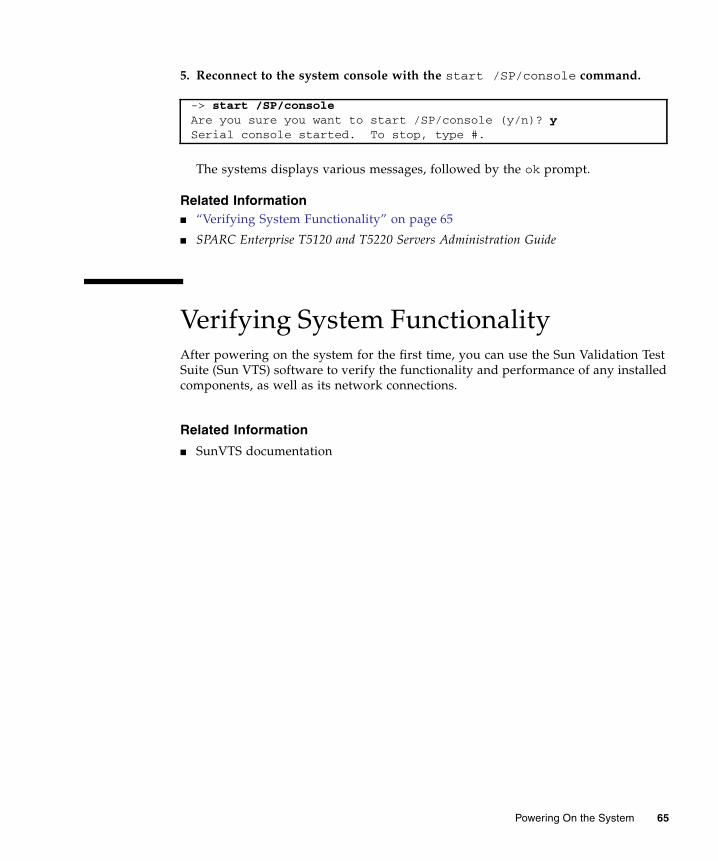
5. Reconnect to the system console with the start /SP/console command.
The systems displays various messages, followed by the ok prompt.
Related Information■ “Verifying System Functionality” on page 65
■ SPARC Enterprise T5120 and T5220 Servers Administration Guide
Verifying System FunctionalityAfter powering on the system for the first time, you can use the Sun Validation TestSuite (Sun VTS) software to verify the functionality and performance of any installedcomponents, as well as its network connections.
Related Information
■ SunVTS documentation
-> start /SP/consoleAre you sure you want to start /SP/console (y/n)? ySerial console started. To stop, type #.
Powering On the System 65

66 SPARC Enterprise T5120 and T5220 Servers Installation Guide • July 2009

Updating the Firmware
This section provides instructions for updating SP firmware.
Related Information
■ “flashupdate command” on page 67
■ “To Update the Firmware” on page 68
flashupdate commandThe flashupdate command updates both the service processor firmware and theserver firmware.
The flash image consists of the following components:
■ Service processor firmware
■ OpenBoot PROM
■ POST
■ Reset/config
■ Sequencer
■ Partition description
Related Information
■ “To Update the Firmware” on page 68
67
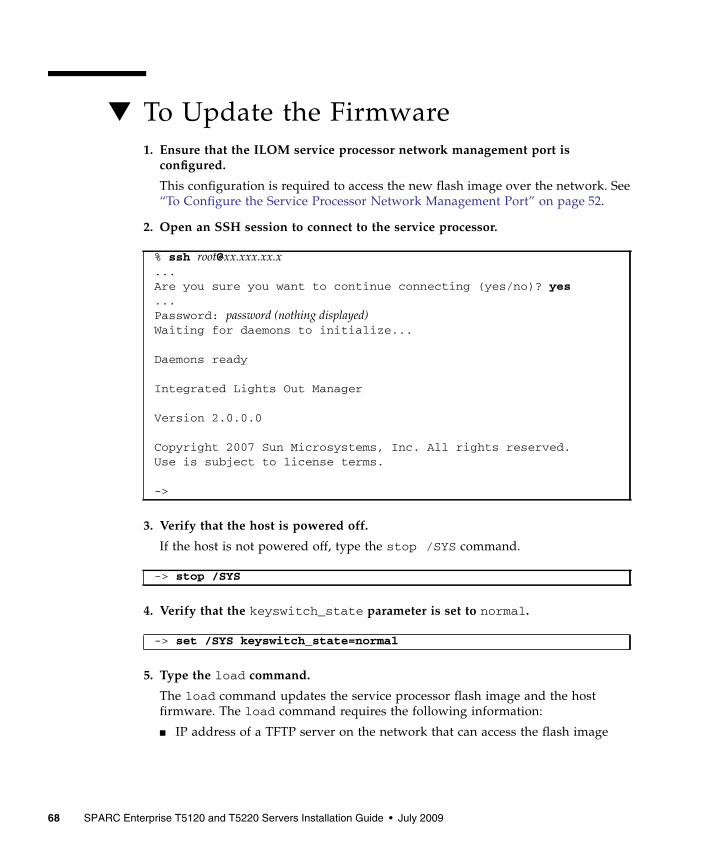
▼ To Update the Firmware1. Ensure that the ILOM service processor network management port is
configured.
This configuration is required to access the new flash image over the network. See“To Configure the Service Processor Network Management Port” on page 52.
2. Open an SSH session to connect to the service processor.
3. Verify that the host is powered off.
If the host is not powered off, type the stop /SYS command.
4. Verify that the keyswitch_state parameter is set to normal.
5. Type the load command.
The load command updates the service processor flash image and the hostfirmware. The load command requires the following information:
■ IP address of a TFTP server on the network that can access the flash image
% ssh [email protected] you sure you want to continue connecting (yes/no)? yes...Password: password (nothing displayed)Waiting for daemons to initialize...
Daemons ready
Integrated Lights Out Manager
Version 2.0.0.0
Copyright 2007 Sun Microsystems, Inc. All rights reserved.Use is subject to license terms.
->
-> stop /SYS
-> set /SYS keyswitch_state=normal
68 SPARC Enterprise T5120 and T5220 Servers Installation Guide • July 2009

■ Full path name to the flash image that the IP address can access
The command usage is as follows:
load [-script] -source tftp://xxx.xxx.xx.xx/pathname
where:
■ -script – Does not prompt for confirmation and acts as if yes was specified
■ -source – Specifies the IP address and full path name (URL) to the flash image
After the flash image has been updated, the system automatically resets.
The service processor resets, runs diagnostics, and returns to the login prompt(on the serial console), similar to this code example:
-> load -source tftp://xxx.xxx.xx.xx/pathname NOTE: A firmware upgrade will cause the server and ILOM to be reset. It is recommended that a clean shutdown of the server be done prior to the upgrade procedure. An upgrade takes about 6 minutes to complete. ILOM will enter a special mode to load new firmware. No other tasks can be performed in ILOM until the firmware upgrade is complete and ILOM is reset.
Are you sure you want to load the specified file (y/n)? yDo you want to preserve the configuration (y/n)? y...............................................................
Firmware update is complete.ILOM will now be restarted with the new firmware.Update complete. Reset device to use new image.
->
U-Boot 1.1.1 (May 23 2007 - 21:30:12)...POST cpu PASSEDPOST ethernet PASSEDHit any key to stop autoboot: 0## Booting image at fe080000 ...
IP Protocols: ICMP, UDP, TCP, IGMP
Checking all file systems...fsck 1.37 (21-Mar-2005)Setting kernel variables ...... done.Mounting local filesystems...Cleaning /tmp /var/run /var/lock.
Updating the Firmware 69

Related Information■ “To Configure the Service Processor Network Management Port” on page 52
Identifying DOC Device Type(G3/G4/H3) ...OK
Configuring network interfaces...Internet Systems Consortium DHCPClient V3.0.1Copyright 2007 Internet Systems Consortium.All rights reserved.For info, please visit http://www.isc.org/products/DHCP
eth0: config: auto-negotiation on, 100FDX, 100HDX, 10FDX, 10HDX.Listening on LPF/eth0/00:14:4f:3f:8c:afSending on LPF/eth0/00:14:4f:3f:8c:afSending on Socket/fallbackDHCPDISCOVER on eth0 to 255.255.255.255 port 67 interval 6eth0: link up, 100 Mbps Full Duplex, auto-negotiation complete.DHCPDISCOVER on eth0 to 255.255.255.255 port 67 interval 15Hostname: hostname.Starting portmap daemon: portmap.Initializing random number generator...done.INIT: Entering runlevel: 3Starting system log daemon: syslogd and klogd.Starting periodic command scheduler: cron.Starting IPMI Stack...... Done.Starting OpenBSD Secure Shell server: sshd.Starting Servicetags listener: stlistener.Starting FRU update program: frutool.
hostname login:
70 SPARC Enterprise T5120 and T5220 Servers Installation Guide • July 2009

Selecting a Boot Device
This section provides instructions on selecting a boot device:
Related Information
■ “Selecting a Boot Device” on page 71
■ “To Select a Boot Device” on page 72
Selecting a Boot DeviceYou specify the boot device by setting an OpenBoot configuration variable calledboot-device. The default setting of this variable is disk net. Because of thissetting, the firmware first attempts to boot from the system hard drive, and if thatfails, from the on-board NET0 Gigabit Ethernet interface.
This procedure assumes that you are familiar with the OpenBoot firmware and thatyou know how to enter the OpenBoot environment. For more information, see theSPARC Enterprise T5120 and T5220 Servers Administration Guide.
Note – The serial management port on the ILOM card is preconfigured as the defaultsystem console port. For more information, see the SPARC Enterprise T5120 and T5220Servers Overview.
If you want to boot from a network, you must connect the network interface to thenetwork.
71

▼ To Select a Boot Device● At the ok prompt, type:
where the device-specifier is one of the following:
■ cdrom – Specifies the DVD drive
■ disk – Specifies the system boot disk (internal disk 0 by default)
■ disk0 – Specifies internal drive 0
■ disk1 – Specifies internal drive 1
■ disk2 – Specifies internal drive 2
■ disk3 – Specifies internal drive 3
■ net, net0, net1, net2, net3 – Specifies the network interfaces
■ full path name – Specifies the device or network interface by its full path name
Note – The Solaris OS modifies the boot-device variable to its full path name, notthe alias name. If you choose a nondefault boot-device variable, the Solaris OSspecifies the full device path of the boot device.
Note – You can specify the name of the program to be booted as well as the way theboot program operates. For more information, refer to the OpenBoot 4.x CommandReference Manual for your specific Solaris OS release. This document is available at:(http://www.sun.com/documentation)
If you want to specify a network interface other than an on-board Ethernetinterface as the default boot device, you can determine the full path name ofeach interface by typing either of the following commands:
The show-devs command lists the system devices and displays the full pathname of each PCI device.
Related Information■ OpenBoot Documentation
■ OpenBoot 4.x Command Reference Manual
ok setenv boot-device device-specifier
ok show-devsok show-nets
72 SPARC Enterprise T5120 and T5220 Servers Installation Guide • July 2009

Installing the Servers With theExpress Rail Rackmounting Kit
This section provides instructions for installing the servers in an equipment rackwith express (snap-in) rails. The express rail rackmounting kit installs quickly, anddoes not require mounting screws or nuts. The kit and the installation procedures arethe same for both the SPARC Enterprise T5120 and T5220 servers.
Note – If your rackmounting kit came with its own instructions, use the instructionsin your rackmounting kit instead of the instructions in this section. After performingthe server installation, proceed to “Powering On the System” on page 43 forfirst-time power on.
Note – The procedures in this section are the same for both the 1U and 2U servers.The illustrations show a 2U server only as an example.
This chapter contains the following sections:
■ “Slide Rail Assembly Notes for the Express Rail Rackmounting Kit” on page 74
■ “Installing the Servers in a Rack With Express Rails” on page 76
■ “Installing the Cable Management Arm” on page 83
■ “Dismounting the Server” on page 84
Note – References to left and right are from your viewpoint as you face either thefront or the rear of the system.
Related Information
■ “Slide Rail Assembly Notes for the Express Rail Rackmounting Kit” on page 74
■ “Installing the Servers in a Rack With Express Rails” on page 76
73

Slide Rail Assembly Notes for theExpress Rail Rackmounting KitThe express rail rackmounting kit has two slide rail assemblies. A slide rail assemblycan be installed on either the right or left side of the rack.
Each slide rail assembly consists of a three-section slide rail and a removablemounting bracket.
FIGURE: Sections of the Express Rail Slide Rail Assembly
■ The front, middle, and rear sections form the slide rail. The middle and rear sectionshave holes for mounting and adjust to fit rack depths from 24 in. (61 cm) to 36.5 in.(93 cm). The front section can be extended to allow movement of the server out ofthe rack.
Figure Legend
1 Mounting bracket
2 Front section
3 Middle section
4 Rear section
74 SPARC Enterprise T5120 and T5220 Servers Installation Guide • July 2009

■ The removable mounting bracket slides 14.5 in. (37 cm) out of the slide rail, thenlocks in place. If you unlock the mounting bracket at this point, it slides anadditional 14.5 in. (37 cm) before separating from the slide rail. You can thenmount the mounting bracket to the right or left side of the server chassis.
■ Note that there are six locks in a slide rail assembly. Four are on the mountingbracket. Two locks are on the slide rail.
FIGURE: Locating the Locks on the Slide Rail Assembly for the SPARC Enterprise T5220Server
Installing the Servers With the Express Rail Rackmounting Kit 75

Related Information
■ “Installing the Servers in a Rack With Express Rails” on page 76
Installing the Servers in a Rack WithExpress Rails
Note – Ensure that you have all of the parts in the rackmounting kit before youbegin installation.
The rackmounting kit contains two slide rail assemblies, which can be installed oneither the right or left side of the rack.
A slide rail assembly consists of two parts, a slide rail and a removable mountingbracket. The slide rail attaches to the rack posts. The mounting bracket attaches to theserver chassis.
Related Information
■ “To Install the Slide Rail Assemblies” on page 76
▼ To Install the Slide Rail Assemblies1. Pull both mounting brackets completely out of their respective slide rails.
a. Simultaneously press and hold the upper and lower lock buttons of the sliderail lock.
76 SPARC Enterprise T5120 and T5220 Servers Installation Guide • July 2009

FIGURE: Unlocking the Express Rail Slide Rail Assembly
b. Pull the mounting bracket out until it stops.
c. Slide the mounting bracket release button to the left, then slide the mountingbracket completely out of the slide rail.
Installing the Servers With the Express Rail Rackmounting Kit 77

FIGURE: Express Rail Mounting Bracket Release Button
2. Attach a mounting bracket to the right side of the server chassis.
a. Position the mounting bracket against the chassis. Ensure that the slide raillock is at the front and the keyed openings on the mounting bracket arealigned with the locating pins on the side of the chassis.
78 SPARC Enterprise T5120 and T5220 Servers Installation Guide • July 2009
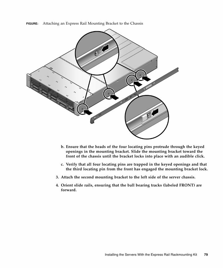
FIGURE: Attaching an Express Rail Mounting Bracket to the Chassis
b. Ensure that the heads of the four locating pins protrude through the keyedopenings in the mounting bracket. Slide the mounting bracket toward thefront of the chassis until the bracket locks into place with an audible click.
c. Verify that all four locating pins are trapped in the keyed openings and thatthe third locating pin from the front has engaged the mounting bracket lock.
3. Attach the second mounting bracket to the left side of the server chassis.
4. Orient slide rails, ensuring that the ball bearing tracks (labeled FRONT) areforward.
Installing the Servers With the Express Rail Rackmounting Kit 79

FIGURE: Express Rail Slide Rails Orientation for Installation
5. Extend the slide rails (outer section) to fit the rack and attach the slide rails tothe rack.
You hear an audible click when the rails securely attach to the rack.
80 SPARC Enterprise T5120 and T5220 Servers Installation Guide • July 2009

FIGURE: Attaching Express Slide Rails to the Rack
Caution – Deploy the antitilt feature on the rack before continuing the installation.
Related Information■ “To Insert and Lock the Server in the Rack” on page 81
▼ To Insert and Lock the Server in the Rack1. Deploy the antitilt feature, if the rack is so equipped.
Caution – The weight of the servers on extended slide rails can be enough tooverturn an equipment rack.
Caution – The 2U server weighs approximately 55 lb (25 kg). Two people arerequired to lift and mount the server into a rack enclosure when using theprocedures in this chapter.
Installing the Servers With the Express Rail Rackmounting Kit 81

2. Insert the ends of the mounting brackets into the sliding rails.
3. Slide the server approximately halfway into the chassis.
FIGURE: Inserting Express Rail Mounting Brackets Into the Slide Rails
4. Slide the green release tab.
5. Push the server all the way into the rack until it locks into place.
82 SPARC Enterprise T5120 and T5220 Servers Installation Guide • July 2009

FIGURE: Sliding the Express Rail Release Tab and Securing the Server in the Rack
Caution – Before continuing, verify that the server is securely mounted in the rackand that the slide rails are locked in the mounting brackets.
Related Information■ SPARC Enterprise T5120 and T5220 Servers Getting Started Guide
■ SPARC Enterprise T5120 and T5220 Servers Getting Started Guide (DC)
Installing the Cable Management ArmThe rackmounting kit for each server comes with the same cable management arm(CMA) assembly. The CMA installation procedures are the same for both servers.
See “Installing the Cable Management Arm for Both Servers” on page 27.
Installing the Servers With the Express Rail Rackmounting Kit 83

Related Information
■ “Installing the Cable Management Arm for Both Servers” on page 27
■ “Connecting the Server Cables for Both Servers” on page 34
■ “Managing Cables With the CMA” on page 39
Dismounting the Server
Caution – To prevent damage to your server, do not move the rack while the serveris mounted.
To install or replace internal parts in the server, you must first remove the serverfrom the rack. For the removal procedure, refer to the SPARC Enterprise T5120 andT5220 Servers Service Manual.
Related Information
■ SPARC Enterprise T5120 and T5220 Servers Service Manual
84 SPARC Enterprise T5120 and T5220 Servers Installation Guide • July 2009

Assembling and Installing DCPower Cables for the SPARCEnterprise T5120 Server
This section provides the following DC input power information for the SPARCEnterprise T5120 server:
■ “Requirements for Servers With DC Input Power” on page 85
■ “Assembling and Installing the DC Input Power Cables” on page 87
■ “Connecting the DC Input Power Cords to the Server” on page 96
The procedures in this section are only for the SPARC Enterprise T5120 server. Donot use this section for assembling the DC power cables for the SPARC EnterpriseT5220 server.
Related Information
■ “Assembling and Installing the DC Input Power Cables” on page 101
Requirements for Servers With DC InputPowerThe following restrictions apply to the SPARC Enterprise T5120 server with DC inputpower:
■ The DC version of the server must be installed in a restricted-access location.According to the intent of the National Electrical Code, a restricted-access locationis an area intended for qualified or trained personnel only and has accesscontrolled by a locking mechanism, such as a key lock or an access card system.
■ The server must not be directly connected to centralized DC mains.
85

Related Information
■ “DC Supply and Ground Conductor Requirements” on page 86
DC Supply and Ground ConductorRequirementsThe server must meet the following:
■ Suitable conductor material: use copper conductors only
■ Power supply connections through the input connector: 12 AWG (between theserver and the source). There are three conductors:
■ -48V or -60V (negative terminal)
■ Chassis ground connection
■ -48V or -60V Return (positive terminal)
■ System ground conductor: 12 AWG (to be connected to the chassis)
■ Cable insulation rating: Minimum of 75˚C (167˚F), low smoke fume (LSF), flameretardant
■ Provide a Wago Type 721-103/037-000 mating connector for proper connection tothe DC connectors supplied with the server (Wago Type 721).
■ Branch circuit cable insulation color: Per applicable National Electrical Codes
■ Grounding cable insulation color: Green/Yellow
■ DC power source must meet TNV-2 requirements as defined by UL 60950-1 andIEC 60950-1
Note – Depending on the DC power source, the -48V or -60V (negative terminal)might be marked with a minus (-) symbol, and the -48V or -60V Return (positiveterminal) might be marked with a positive (+) symbol.
When attaching DC cables, keep the following requirement in mind:
Caution – You must restrict the connection of the server to the DC power source tominimize the possibility that transient energy will appear on the main input to theequipment. The DC battery power source must be in the same premises as the server.The server cannot be in one building with the power source in another building.
86 SPARC Enterprise T5120 and T5220 Servers Installation Guide • July 2009

Related Information
■ “Overcurrent Protection Requirements” on page 87
Overcurrent Protection Requirements■ Overcurrent protection devices must be provided as part of each equipment rack.
■ Circuit breakers must be located between the DC power source and the server. Useone 20 A fast-trip double-pole DC-rated circuit breaker for each power supplyunit.
Note – Overcurrent protection devices must meet applicable national and localelectrical safety codes and be approved for the intended application.
Related Information
■ “Assembling and Installing the DC Input Power Cables” on page 87
Assembling and Installing the DC InputPower CablesThe following procedure describes how to assemble the DC input power cables forthe SPARC Enterprise T5120 server.
Assemble one cable for each DC power supply in your server.
Assembling and Installing DC Power Cables for the SPARC Enterprise T5120 Server 87

Before you begin the installation procedure, verify that the required conditionsdescribed in the following table have been satisfied.
Related Information
■ “To Assemble the DC Input Power Cables” on page 88
▼ To Assemble the DC Input Power Cables1. Turn off power from the DC power source using the circuit breakers.
Caution – Do not proceed with these instructions until you have turned off thepower from the DC power source through the circuit breakers.
2. Identify the parts that you will use to assemble the DC input power cables
For each cable, you need the three parts shown in the figure below. These itemsare provided in the shipping kit that came with your server.
TABLE: Prerequisites Not Covered by the DC Cable Installation Procedure
Prerequisite Condition Responsible Party
Install a DC power source that meets the server’s input powerspecifications.
Customer
Secure DC power cables that meet the server’s power cablingspecifications.
Customer
Attach the DC input plug to the DC input power cables. The input plugis provided in the server’s shipping kit.
Customer
88 SPARC Enterprise T5120 and T5220 Servers Installation Guide • July 2009

FIGURE: DC Connection Parts
3. Locate the three wires coming from the DC power source that will be used inthe connection to your unit:
■ -48V or -60V (negative terminal)
■ Chassis ground
■ -48V or -60V Return (positive terminal)
Note – Depending on the DC power source, the -48V or -60V (negative terminal)might be marked with a minus (-) symbol, and the -48V or -60V Return (positiveterminal) might be marked with a positive (+) symbol.
Figure Legend
1 Strain relief housing
2 DC input plug
3 Cage clamp operating lever
Assembling and Installing DC Power Cables for the SPARC Enterprise T5120 Server 89

4. Strip 5/16 inches (8 mm) of insulation from each of the wires coming from theDC power source.
Do not strip more than 5/16 inches (8 mm) from each wire. Doing so leavesuninsulated wire exposed from the DC connector after the assembly is complete.
FIGURE: Stripping the Insulation From the Wire
5. Open the cage clamp for this section of the DC input plug by taking one of thefollowing actions:
■ Insert the tip of the cage clamp operating lever into the rectangular holedirectly above the hole in the DC input plug where you want to insert the firstwire. Press down on the cage clamp operating lever.
■ Insert a small slotted screwdriver into the rectangular hole directly above thehole in the DC input plug where you want to insert the first wire, and push into open the cage clamp.
Figure Legend
1 Cable stripped to 5/16 in., or 8mm
90 SPARC Enterprise T5120 and T5220 Servers Installation Guide • July 2009

FIGURE: Opening the DC Input Plug Cage Clamp Using the Cage Clamp Operating Lever
Figure Legend
1 Top of input plug
Assembling and Installing DC Power Cables for the SPARC Enterprise T5120 Server 91

FIGURE: Opening the Cage Clamp Using a Screwdriver
6. Feed the exposed section of the appropriate wire into the round hole in the DCinput plug.
FIGURE: Connector Wiring Assignments
Figure Legend
1 Top of input plug
Figure Legend
1 Top of connector 3 From chassis ground (green/yellow)
2 From -48V or -60V return 4 From -48V or -60V
92 SPARC Enterprise T5120 and T5220 Servers Installation Guide • July 2009

Note – If you need to remove a wire from the DC input plug, insert the cage clampoperating lever or a small screwdriver as described in Step 5, and pull the wire fromthe DC input plug.
7. Release the lever or remove the tool to secure the wire into the connector.
8. Repeat Step 5 and Step 7 for the other two wires to complete the assembly of theDC input power cable.
9. Repeat this procedure to create as many DC input power cables as you need foryour unit.
▼ To Install the Strain Relief Housings1. Insert the bottom portion of the strain relief housing into the notch on the DC
input plug until it snaps into place.
Ensure that the strain relief housing snaps into place on the DC input plug. Youcannot complete the assembly correctly if the strain relief housing is not snappedinto place.
Assembling and Installing DC Power Cables for the SPARC Enterprise T5120 Server 93

FIGURE: Inserting the Bottom Portion of the Strain Relief Housing
2. Route the three wires coming from the DC power source through the opening atthe end of the bottom portion of the strain relief housing.
FIGURE: Routing the Wires out of the Bottom Portion of the Strain Relief Housing
3. Insert a tie wrap into the bottom portion of the strain relief housing.
94 SPARC Enterprise T5120 and T5220 Servers Installation Guide • July 2009

FIGURE: Securing the Wires to the Strain Relief Housing
4. Loop the tie wrap over the wires and back out of the strain relief housing, andtightening the tie wrap to secure the wires to the strain relief housing.
5. Lower the top portion of the strain relief housing so that the three prongs on thetop portion insert into the openings in the DC input plug.
Push the top and bottom portions of the strain relief housing together until theysnap into place.
Assembling and Installing DC Power Cables for the SPARC Enterprise T5120 Server 95
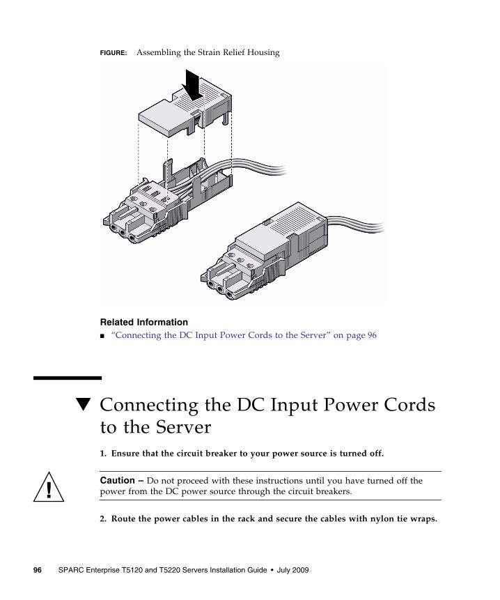
FIGURE: Assembling the Strain Relief Housing
Related Information■ “Connecting the DC Input Power Cords to the Server” on page 96
▼ Connecting the DC Input Power Cordsto the Server1. Ensure that the circuit breaker to your power source is turned off.
Caution – Do not proceed with these instructions until you have turned off thepower from the DC power source through the circuit breakers.
2. Route the power cables in the rack and secure the cables with nylon tie wraps.
96 SPARC Enterprise T5120 and T5220 Servers Installation Guide • July 2009

3. Connect the chassis ground wire to the facility earth ground and ensure thatthis connection has proper bonding.
4. Connect the -48v or -60V return to the -48 v or -60V wires to the circuit breaker.
5. Connect the power wiring to the server by plugging each power cable into theserver power supply units.
6. When you are ready to power up the server, close the circuit breaker andfollowing booting procedure described in, “Powering On the System for the FirstTime” on page 43.
Related Information■ “Assembling and Installing the DC Input Power Cables” on page 87
Assembling and Installing DC Power Cables for the SPARC Enterprise T5120 Server 97

98 SPARC Enterprise T5120 and T5220 Servers Installation Guide • July 2009

Assembling and Installing DCPower Cables for the SPARCEnterprise T5220 Server
This section provides the following DC input power information for the SPARCEnterprise T5220 server:
■ “Requirements for Servers With DC Input Power” on page 99
■ “Assembling and Installing the DC Input Power Cables” on page 101
The procedures in this section are only for the SPARC Enterprise T5220 server.
Do not use this section for assembling the DC power cables for the SPARC EnterpriseT5120 server. Instead, see, “Assembling and Installing the DC Input Power Cables”on page 87.
Requirements for Servers With DC InputPowerThe following restrictions apply to the SPARC Enterprise T5220 server with DC inputpower:
■ The DC version of the server must be installed in a restricted-access location.According to the intent of the National Electrical Code, a restricted-access locationis an area intended for qualified or trained personnel only and has accesscontrolled by a locking mechanism, such as a key lock or an access card system.
■ The server must not be directly connected to centralized DC mains.
DC Supply and Ground Conductor RequirementsThe server ground conductor must meet the following requirements:
■ Suitable conductor material: use copper conductors only
99

■ Power supply connections through the input connector: 8 AWG (between theserver and the source). There are three conductors:
■ -48V or -60V (negative terminal)
■ Chassis ground connection
■ -48V or -60V Return (positive terminal)
■ System ground conductor: 8 AWG (to be connected to the chassis)
■ Cable insulation rating: Minimum of 75˚C (167˚F), low smoke fume (LSF), flameretardant
■ Provide the mating connector, Wago Part Number 51204745, for proper connectionto the DC connectors supplied with the server.
This connector requires a 4mm flat-blade screwdriver to insert wires into theconnector body.
■ Branch circuit cable insulation color: Per applicable National Electrical Codes
■ Grounding cable insulation color: Green/Yellow
■ DC power source must meet TNV-2 requirements as defined by UL 60950-1 andIEC 60950-1
Note – Depending on the DC power source, the -48V or -60V (negative terminal)might be marked with a minus (-) symbol, and the -48V or -60V Return (positiveterminal) might be marked with a positive (+) symbol.
When attaching DC cables, keep the following caution in mind:
Caution – You must restrict the connection of the server to the DC power source tominimize the possibility that transient energy will appear on the main input to theequipment. The DC battery power source must be in the same premises as the server.The server cannot be in one building with the power source in another building.
Overcurrent Protection Requirements■ Overcurrent protection devices must be provided as part of each equipment rack.
■ Circuit breakers must be located between the DC power source and the server. Useone 40 A fast-trip double-pole DC-rated circuit breaker for each power supplyunit.
Note – Overcurrent protection devices must meet applicable national and localelectrical safety codes and be approved for the intended application.
100 SPARC Enterprise T5120 and T5220 Servers Installation Guide • July 2009

Assembling and Installing the DC InputPower CablesThe following procedure describes how to assemble the DC input power cable for theSPARC Enterprise T5220 server.
Assemble one cable for each DC power supply in your server.
Before you begin the installation procedure, verify that the required conditionsdescribed in the following table have been satisfied.
▼ To Assemble the DC Input Power Cables1. Turn off power from the DC power source using the circuit breakers.
Caution – Do not proceed with these instructions until you have turned off thepower from the DC power source through the circuit breakers.
2. Identify the parts that you will use to assemble the DC input power cables.
For each cable, you need the three parts shown in the figure below. These itemsare provided in the shipping kit that came with your server (DC models only).
TABLE: Prerequisites Not Covered by the DC Cable Installation Procedure
Prerequisite Condition Responsible Party
Install a DC power source that meets the server’s input powerspecifications.
Customer
Secure DC power cables that meet the server’s power cablingspecifications.
Customer
Attach the DC input plug to the DC input power cables. The input plugis provided in the server’s shipping kit.
Customer
Assembling and Installing DC Power Cables for the SPARC Enterprise T5220 Server 101

FIGURE: DC Connection Parts
3. Locate the three wires coming from your DC power source that will be used inthe connection to your unit:
■ -48V or -60V (negative terminal)
■ Chassis ground
■ -48V or -60V Return (positive terminal)
Note – Depending on the DC power source, the -48V or -60V (negative terminal)might be marked with a minus (-) symbol, and the -48V or -60V Return (positiveterminal) might be marked with a positive (+) symbol.
4. Strip 1/2 inches (13 mm) of insulation from each of the wires coming from theDC power source.
Do not strip more than 1/2 inches (13 mm) from each wire. Doing so leavesuninsulated wire exposed from the DC connector after the assembly is complete.
Figure Legend
1 DC input plug
2 Cage clamp operating tool or small screwdriver
102 SPARC Enterprise T5120 and T5220 Servers Installation Guide • July 2009

FIGURE: Stripping the Insulation From the Wire
5. Open the cage clamp by inserting the cage clamp tool (or small screwdriver)into the rectangular hole directly above the hole in the DC input plug whereyou want to insert the first wire, and push in to open the cage clamp.
FIGURE: Opening the Cage Clamp Using the Cage Clamp Tool
6. Feed the exposed section of the appropriate wire into the round plug hole in theDC input plug.
Figure Legend
1 Strip the insulation 1/2 in., or 13 mm.
Assembling and Installing DC Power Cables for the SPARC Enterprise T5220 Server 103
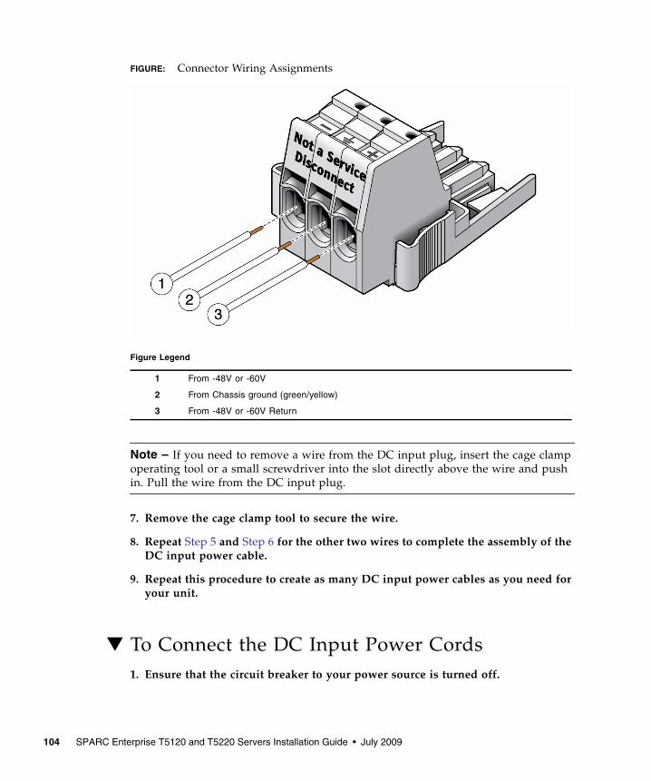
FIGURE: Connector Wiring Assignments
Note – If you need to remove a wire from the DC input plug, insert the cage clampoperating tool or a small screwdriver into the slot directly above the wire and pushin. Pull the wire from the DC input plug.
7. Remove the cage clamp tool to secure the wire.
8. Repeat Step 5 and Step 6 for the other two wires to complete the assembly of theDC input power cable.
9. Repeat this procedure to create as many DC input power cables as you need foryour unit.
▼ To Connect the DC Input Power Cords1. Ensure that the circuit breaker to your power source is turned off.
Figure Legend
1 From -48V or -60V
2 From Chassis ground (green/yellow)
3 From -48V or -60V Return
104 SPARC Enterprise T5120 and T5220 Servers Installation Guide • July 2009

Caution – Do not proceed with these instructions until you have turned off thepower from the DC power source through the circuit breakers.
2. Route the power cables in the rack and secure the cables with nylon tie wraps.
3. Connect the chassis ground wire to the facility earth ground and ensure thatthis connection has proper bonding.
4. Connect the -48V or -60V return to the -48V or -60V wires to the circuit breaker.
5. Connect the power wiring to the server by plugging each power cable into theserver power supply units.
6. When you are ready to power up the server, close the circuit breaker andfollowing booting procedure described in “Powering On the System for the FirstTime” on page 43..
Assembling and Installing DC Power Cables for the SPARC Enterprise T5220 Server 105

106 SPARC Enterprise T5120 and T5220 Servers Installation Guide • July 2009

Index
Symbols#. escape sequence for system console, 64
Aaccessing ILOM command line, 51adapters for serial cables, 36address, IP, 8addresses, web, See web sitesadmin login, setting password for, 51
Bbaud rate for serial terminal, 45bits setting for serial terminal, 45boot
booting the Solaris OS, 60booting the system, 43OpenBoot PROM boot command, 62
buttons, See "slide rail assembly locks"
Ccable management assembly, ?? to 34cable management bracket, description, 18cables
adapters for serial data cables, 36cage clamp operating lever, 89cage clamp operating tool, 102command
set keyswitch, 56, 57command line access, ILOM, 51configuration information needed, 8configuring the network management port, 49connecting to the system console, 58console command, 65
DDB-9 TTY connector, 11DC input plug, 89, 102DC input power, 85, 99DC input power cable, assembling, 87, 101DC input power, connecting, 96, 104definitions, See terms, 19deinstallation of server, 40, 84diagnostics, when run, 47
Eenabling the network management port, 49escape sequence #. for system console, 64example of full disk path, 62
Ffirst time AC power, 43
Ggateway IP address, 8ground conductor requirements, 100ground conductor requirements (DC models), 86
Hhandshaking for serial terminal, no, 45hot-plugging USB ports, 11
IILOM
command line access, 51See also service processor
initializing the system, 58installation instructions, optional components,
reference, 5installing
107

mounting brackets, 76installing optional components, 5IP address, 8
LLEDs, ports, and slots illustrated, 12left and right sides defined, 19levers, locking, See "slide rail assembly locks"locating pins for mounting brackets, 76locations of ports, slots, and LEDs (illustration), 12locks, See "slide rail assembly locks"logging into service processor
using network management port, 51, 55using serial management port, 51
Mmap of OpenBoot PROM devices, 60minimum cable connections, 10modem not for use with the SER MGT serial
management port, 36mounting bracket
locating pins on chassis, 76preparation for installation, 76removing from slide rail, 76unlocking, 76
mounting screws for rack, 23
Nnetmask, 8network management port
configuring and enabling, 49not operational until configured, 9, 49
OOpenBoot PROM device map, 60optional components, installation instructions in
service manual, 5overcurrent protection device (DC models), 87, 100
Pparity for serial terminal, no, 45password command, 51path names, 60pins, mounting bracket locating, 76ports, slots, and LEDs illustrated, 12
power cycling the system, 63powering on the system for the first time, 43poweroff command, 64poweron command, 56, 59
Rremoving server from rack, 40, 84reset
resetting the system with uadmin, 63restricted-access location (DC models), 85right and left sides defined, 19right side defined, 19RJ-45 cable, 11
Sscrews for rack mounting, 23serial terminal
settings, 45service processor
access with network management port, 55access with serial management port, 51connecting to the system console, 58network management port not operational until
configured, 9powering on for the first time, 44powering on the system, 56See also ILOMset command, 53
set command, 53show /SP/network command, 54show-disks command, 61slide rail assembly locks illustrated
front slide rail locks, 20middle section lever, 21mounting bracket locating pin lock, 23mounting bracket release button, 21
slide rail spacing tool, 24slots, ports, and LEDs illustrated, 12Solaris media kit contents, 10spacing tool for slide rails, 24Standby mode, 39standby voltage causes service processor to power
on, 9standby voltage, 3.3v, 47stop bit, 45
108 SPARC Enterprise T5120 and T5220 Servers Installation Guide • July 2009

strain relief housing, 89, 93system console escape sequence #., 64
Tterms
left and right sides, 19slide rail assembly, 15, 74
topic guidelines, 1, 19, 43, 71, 73, 85, 99TTYA serial port, 11
Uuadmin command, 63, 64
unlocking mounting bracket, 76
Index 109

110 SPARC Enterprise T5120 and T5220 Servers Installation Guide • July 2009