Embed Size (px)
Citation preview

Spanning Tree ProtocolAnd Other Advanced Ethernet Topics
2E1623Data Links and LocalArea Networks

2
Learning Bridges—Loop Problem
From B. A. Forouzan: Data Communications and Networking, 3rd ed, McGraw-Hill
3
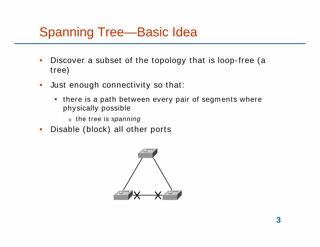
Spanning Tree—Basic Idea
• Discover a subset of the topology that is loop-free (a tree)
• Just enough connectivity so that:
there is a path between every pair of segments where physically possible
o the tree is spanning
• Disable (block) all other ports

4
Spanning Tree Starting Point
• Each bridge has a unique ID
• Each port has a unique ID within the bridge
• A cost can be calculated for each path between two bridges
From B. A. Forouzan: Data Communications and Networking, 3rd ed, McGraw-Hill

5
Spanning Tree Process
1. The node with the smallest ID is selected the root bridge
2. On each bridge, select a root port
Port with the least cost path to the root bridge
3. On each LAN segment, select a designated bridge
Bridge with least cost path to root bridge
o If two bridges have same cost, select the bridge with smallest ID
Mark the corresponding port as the designated port
4. Forward frames only on marked ports
Designated ports and root ports
Block on the others

6
Before Spanning Tree
From B. A. Forouzan: Data Communications and Networking, 3rd ed, McGraw-Hill

7
Applying Spanning Tree
From B. A. Forouzan: Data Communications and Networking, 3rd ed, McGraw-Hill

8
Forwarding Ports and Blocking Ports
• Note that STP is not a routing protocol
In the sense that it does not optimize routing
Traffic concentration towards the root
Blocked

9

10
Spanning Tree Protocol
• Protocol to calculate a spanning tree
• Convergence
All bridges should reach a unified view of the spanning tree
• Special frames sent between neighbourswitches
Bridge Protocol Data Units, BPDUs
Not forwarded!
11
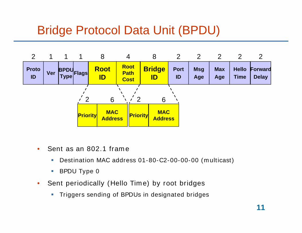
Bridge Protocol Data Unit (BPDU)
• Sent as an 802.1 frame
Destination MAC address 01-80-C2-00-00-00 (multicast)
BPDU Type 0
• Sent periodically (Hello Time) by root bridges
Triggers sending of BPDUs in designated bridges
ProtoID
2
Priority MACAddress
2 6
RootID
8
Ver
1
BPDUType
1
Flags
1RootPathCost
4
BridgeID
8
PortID
2
MsgAge
2
MaxAge
2
HelloTime
2
ForwardDelay
2
Priority MACAddress
2 6

12
<A,0,A><A,0,A><B,0,B> <C,0,C>
Initial State
I am root
I am root I am root
<B,0,B>
<C,0,C>
<Root ID, Root Path Cost, Bridge ID>
B C
A

13
<A,0,A><A,0,A>
Root Bridge Recognized
I am root
I am designated
<A,1,B>
<A,1,C>
<Root ID, Root Path Cost, Bridge ID>
B C
A
I am designated

14
<A,0,A><A,0,A>
Designated Bridge Recognized
I am root
I am designated
<A,1,B>
<Root ID, Root Path Cost, Bridge ID>
B C
A
15
<A,0,A><A,0,A>
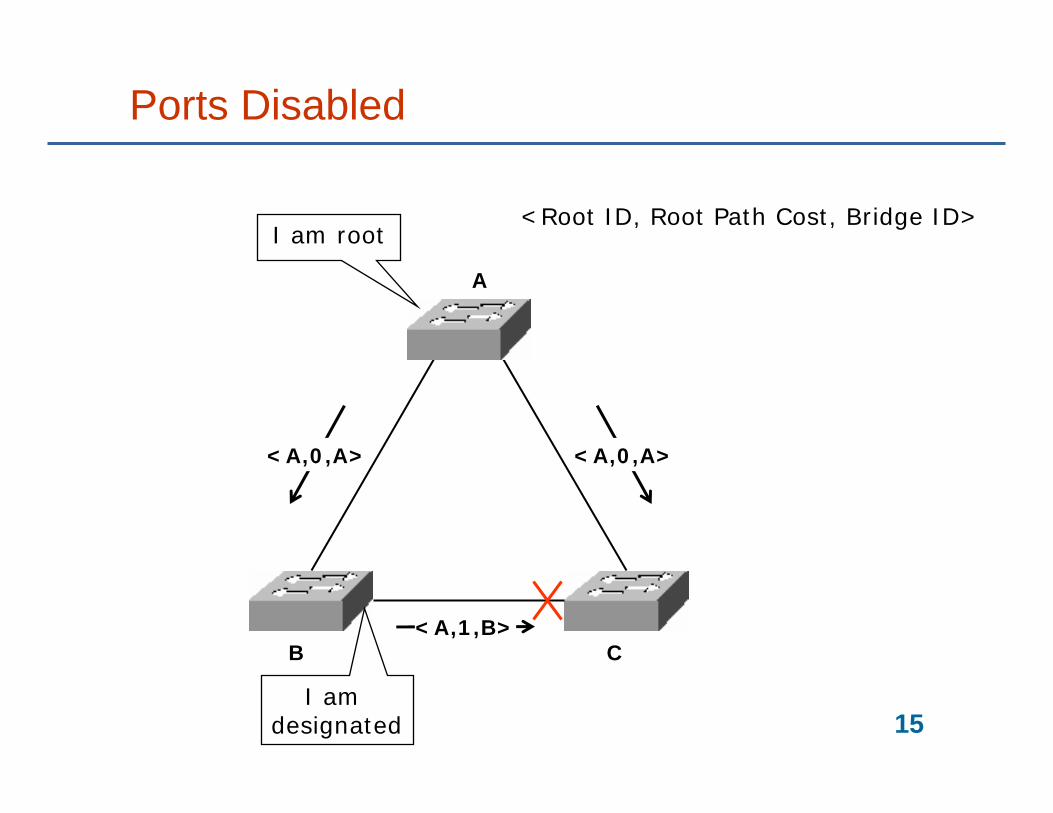
Ports Disabled
I am root
I am designated
<A,1,B>
<Root ID, Root Path Cost, Bridge ID>
B C
A

16
Topology Changes and Learning Table
• Entries in learning table expires
Normally after 5 minutes
Incorrect forwarding
o “Black hole”
• Solution:
Faster expiration time when network configuration has changed
Topology Change Notification PDU

17
Topology Change Notification
• Topology change at a bridge
Port failure
No periodic configuration BPDUs
Port status change
• Bridge sends spontaneous BPDU
Topology Change Notification BPDU
BPDU type 0x80
ProtoID
2
RootID
8
Ver
1
BPDUType
1
Flags
1RootPathCost
4
BridgeID
8
PortID
2
Msgage
2
MaxAge
2
HelloTime
2
ForwardDelay
2
TCN
TC

18
<A,0,A,TC, D>
<TCA>
<TC>
Topology Change
I am root
Configuration BPDU: <Root ID, Root Path Cost, Bridge ID, Flags, Forward Delay>
B C
A
<A,0,A,TC, D>
TCN BPDU: <Flags>
Forwarding Delay shorter than normal

19
Spanning Tree Protocol Timing
• Protocol is timer driven
• Too short timers can give loops and instabilities
• Too long timers can give long convergence times
Until network reaches a stable spanning tree configuration
ProtoID
2
RootID
8
Ver
1
BPDUType
1
Flags
1RootPathCost
4
BridgeID
8
PortID
2
Msgage
2
MaxAge
2
HelloTime
2
ForwardDelay
2

20
<A,0,A><A,0,A>
Designated Bridge Recognized
I am root
I am designated
<A,1,B>
<Root ID, Root Path Cost, Bridge ID>
B C
A

21
Ports Disabled
I am root
I am designated
B C
A

22
Port States
ListeningBPDU processing, no
learning, no forwarding
BlockingNo BPDU processing, no learning, no forwarding
LearningBPDU processing,
learning, no forwarding
ForwardingBPDU processing,
learning, forwarding
Forward Delay timeout
Forward Delay timeout
Max Age timeout
Blocked by algorithm
Blocked by algorithm
Blocked by algorithm

23
Rapid Spanning Tree Protocol
• Ordinary STP takes 30 – 50 seconds to converge, with default settings
• Rapid Spanning Tree Protocol (RSTP)
IEEE 802.1w
Full-duplex mode
o No shared links

24
RSTP vs STP
• RSTP has two more port designations
Alternate Port—backup for Root Port
Backup port—backup for Designated Port on the segment
• In RSTP, all bridges send BPDUs automatically
While in STP, the root triggers BPDUs
• In RSTP, bridges act to bring the network to convergence
While in STP, bridges passively wait for time-outs before changing port states

Virtual Local Area Networks

26
Virtual LANs (VLAN)
• Need a way to divide the LAN into different parts
Without physical reconfiguration
• Moving stations without reconfigurations
• Create virtual workgroups
• Keep broadcasts isolated
• Keep different protocols from each other

27
VLAN Divides LAN Into Logical Groups
From B. A. Forouzan: Data Communications and Networking, 3rd ed, McGraw-Hill

28
VLAN Grouping
• How is VLAN membership determined?
Port number
o Ports 1, 2, 7: VLAN 1
o Ports 3, 4, 5, 6: VLAN 2
• MAC address
• Frame tagging
VLAN trunking
Many VLANs over the same link
29
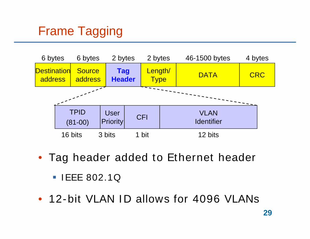
Frame Tagging
• Tag header added to Ethernet header
IEEE 802.1Q
• 12-bit VLAN ID allows for 4096 VLANs
Destinationaddress
Sourceaddress
TagHeader
Length/Type DATA CRC
TPID(81-00)
UserPriority CFI VLAN
Identifier
6 bytes 6 bytes 2 bytes 46-1500 bytes 4 bytes
16 bits 3 bits 1 bit 12 bits
2 bytes

30
Spanning Trees and VLANs
• Per VLAN Spanning Tree
One spanning tree per VLAN
Many spanning tree instances to maintain
Different roots in different STs
o load sharing
• Common Spanning Tree
One spanning tree for all VLANs
Simple, but all traffic goes the same way

31
Multiple Spanning Tree
• Multiple Spanning Tree Protocol (MSTP)
• Network organized in regions
• Regions have their own Multiple Spanning Tree Instances (spanning-tree topologies)
VLANs are associated to MSTIs
• One common spanning tree (CST) for the entire network
• MSTP based on RSTP (Rapid STP)

32
VLAN Signalling
• GVRP

Autonegotiation

34
Ethernet Autonegotiation
• Incompatible rx/tx modes
Full/half duplex
10/100/1000 Mb/s
• Autonegotiation to allow two devices to agree on speed and duplex mode
• Based on 10BASE-T “heartbeat”
Normal Link Pulse
Sent every 16 ms on idle link

35
Link Code Word
• 100BASE-T “Fast Link Pulse”
• 16-bit code word, with a “Technology ability field” (8 bits)
100BASE-T full duplex
100BASE-T4
100BASE-T
10BASE-T full duplex
…
• Misconfiguration problems
Connectivity loss or performance degradation
36
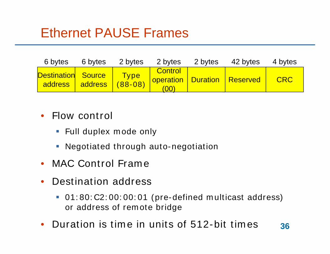
Ethernet PAUSE Frames
• Flow control
Full duplex mode only
Negotiated through auto-negotiation
• MAC Control Frame
• Destination address
01:80:C2:00:00:01 (pre-defined multicast address) or address of remote bridge
• Duration is time in units of 512-bit times
Destinationaddress
Sourceaddress
Type(88-08)
Controloperation
(00)Reserved CRC
6 bytes 6 bytes 2 bytes 42 bytes 4 bytes2 bytes
Duration
2 bytes

Quality of Service and Multicast

38
Quality of Service Switching
• Class of Service
User Priority field in IEEE 802.1Q header
0 – 7, with 7 as highest priority value
Destinationaddress
Sourceaddress
TagHeader
Length/Type DATA CRC
TPID(81-00)
UserPriority CFI VLAN
Identifier
6 bytes 6 bytes 2 bytes 46-1500 bytes 4 bytes
16 bits 3 bits 1 bit 12 bits
2 bytes
39
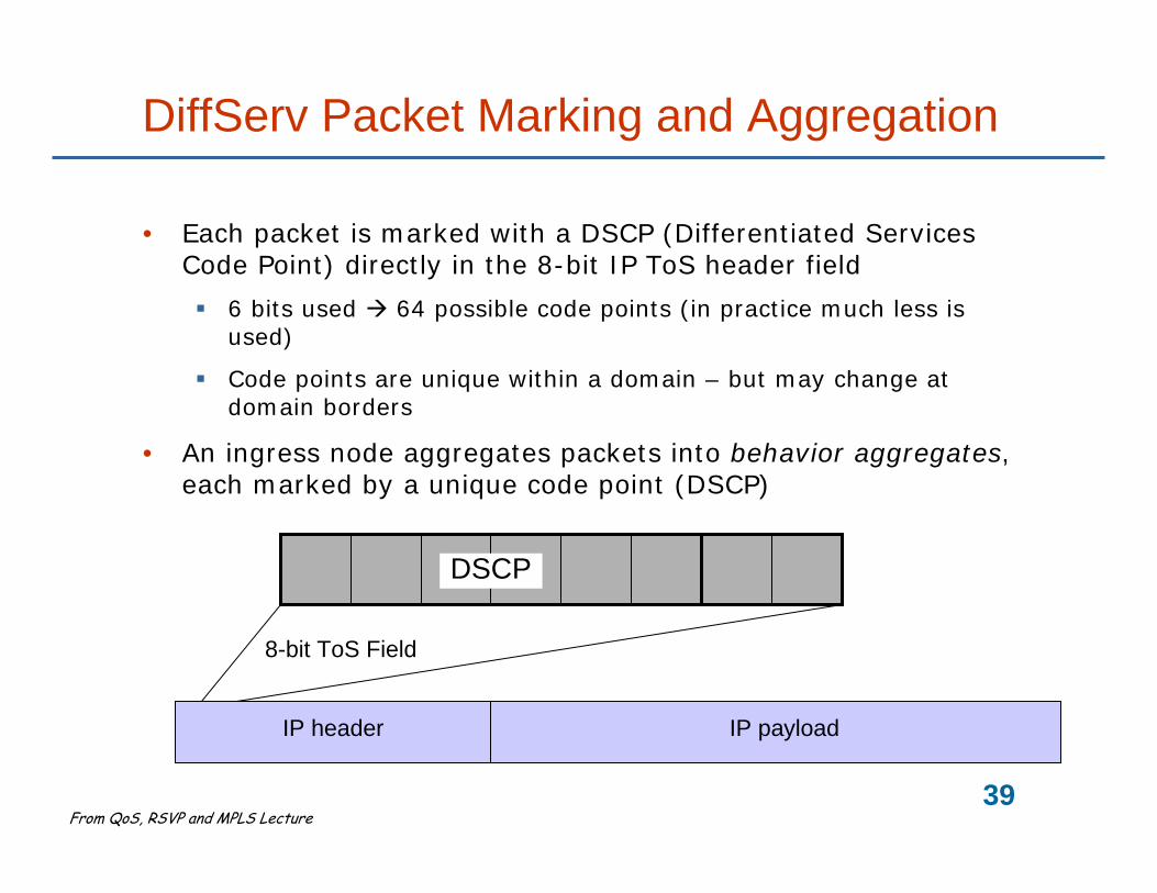
DiffServ Packet Marking and Aggregation
• Each packet is marked with a DSCP (Differentiated Services Code Point) directly in the 8-bit IP ToS header field
6 bits used 64 possible code points (in practice much less is used)
Code points are unique within a domain – but may change at domain borders
• An ingress node aggregates packets into behavior aggregates, each marked by a unique code point (DSCP)
DSCP
IP header IP payload
8-bit ToS Field
From QoS, RSVP and MPLS Lecture

40
Quality of Service Switching
• QoS processing depends on
QoS configuration of port
IP DSCP
o Ignored, or set to predefined value
802.1Q CoS
o Ignored, set to predefined value, or computed from DSCP
…

41
Multicast
• Multicast traffic is, by default, flooded
Increases traffic load
• Switches implement IGMP Snooping
Internet Group Management Protocol
o Like ICMP
o Monitor “Membership Reports” and “Leave Reports”
o Only forward multicast frames to ports where there are receivers
MAC multicast group address is calculated from IP multicast address
o 25 static bits (01:00:5e:0) plus last 23 bits from IP address
o Hashing—multiple IP addresses map to the same MAC address

42
Summary
• Spanning TreeProtocol
Port disabling
Bridge PDUs
Rapid Spanning TreeProtocol (RSTP)
• VLANs
IEEE 802.1Q
Multiple SpanningTree Protocol (MSTP)
• Autonegotiation
Half/full duplex
Speed
Flow control
…
• Quality of Service
• Multicast

43
Reading Instructions
• Behrouz A. Forouzan, ”Data Communications and Networking,” third edition
14 Local Area Networks: Ethernet
o 14.1 Traditional Ethernet
o 14.2 Fast Ethernet
o 14.3 Gigabit Ethernet
16 Connecting LANs, Backbone Networks, and Virtual LANs
o 16.1 Connecting Devices
o 16.3 Virtual LANs
• Backes, F., "Transparent bridges for interconnection of IEEE 802 LANs," IEEE Network, Vol. 2, No. 1. 1988