Embed Size (px)
Citation preview
InstructionRead these instructions carefully before use.Please keep these instruction after assembling.
SpacewalkerOrd. No. 00 6137
GB
Safety precautionsThis radio control model is not a toy!
Not suitable for persons under 14 years!
* First-time builders should seek advice people having building experience in order to assemble the model correctly and to produce its performance to full extent.* Assemble this kit only in places out of children’s reach!* Take enough safety precautions prior to operating this model. You are responsible for this model’s assembly and safe operation!* Always keep this instruction manual ready at hand for quick reference, even after completing the assembly.
!
2
Sicherheitshinweise
Contents Safety Information 2General Information 2Technical data 2Highlights 2Box contents 3
Building the Model 3 - 15Control Throws and Centre of Gravity 15Recommended Accessories 16Plans 17 / 18
Safety InformationFlying models are not toys, and should only be operated by res-ponsible clear thinking people. Assembling and maintaining mo-dels requires a basic level of technical skill, and a sensible logical approach.
Any error in building, repairing or maintaining the model could result in serious injury or damage. Technical problems or an incor-rectly assembled model may lead to the propeller unexpectedly be-ginning to turn. Always stay out of the vicinity of rotating propellersand never allow any item to come into contact with a spinning prop. As neither the manufacturer or the dealer has any influence over the way that models are operated they can accept no respon-sibility for and damage caused.
If this model is the first radio controlled model which you are att-empting to build or fly, you should secure the assistance of an ex-perienced model pilot. Your local dealer will be able to assist you in locating your local model aircraft club or experienced pilots in your area. NEVER fly your model over people and never operate themodel in way which may endanger people or animals. Before yourfirst flight you should conduct a range check of the radio control system, secure the model to a solid object, and ensure that you have full control of all functions with the antennae collapsed over adistance of at least 25 metres. Before and after every flight inspectthe model for damage, and rectify any faults before you attempt totake off. The operator is responsible for any damage caused by theoperation of flying models.
Always observe any local laws regarding the operation of modelaircraft.
Furthermore, the following instructions must be followed: - The kit contains small parts which may cause choking if swallowed, keep away from small children.- The model should not be changed in any way, doing so will invalidate the guarantee.- Never come into contact with rotating parts.- Do not fly over wet ground or grass as water will damage the models electrical components- Do not expose the model or batteries to direct sunlight, always keep them in the shade.- Inspect the model before and after every flight for damage.- Only ever fly the model if it is in perfect working order.- The model can only be flown in good weather. Do not fly in wind, rain or thunder storms.- Find a place to fly which complies with any laws, and is free from obstacles such as trees, houses or power cables.- Remember that your model is made from such materials as plastic and wood, and as such is inflammable. Keep it away from any open flame, or high temperatures.- When operating the model, switch on the transmitter first and then the aircraft, switch off in the reverse order.- Always ensure that the throttle stick is in the low position before you switch on.
General Information As the company JAMARA e.K. has no influence over the use, main-tenance or conditions under which our products will operate, we accept no responsibility for any damage caused be it of a physical,financial or theoretical nature.
JAMARA e.K. will accept no claim against it which results directly orindirectly from the operation or use of ist products. Your StatutoryRights apply, any claim made against us will be based solely on theretail price of the product, and limited to the model only. This willnot apply if we are proved to be legally responsible or when grossnegligence can be proved.
Attention!In some countries it is a legal requirement to carry third Partyindemnity insurance when operating a radio controlled mo-del. Please ask your local dealer, governing body or yourinsurance company for details.
Attention!Switch the transmitter on first then the model.When you are finisished first switch off the model then thetransmitter.
Technical dataWing span ~ 990 mmLength ~ 690 mmWeight ~ 600 ~ 650 g RC 4 channel / 4 servosMotor Electric Motor
Highlights:•Lasercutkit•Idealtohavewithyouatalltimes•Preparedforretracts(onlyBonanza)•Aileron,elevator,verticalfinandthrottle•Fuselagemadeofbalsaandplywood•Wingsmadeofwoodinribconstruction
3
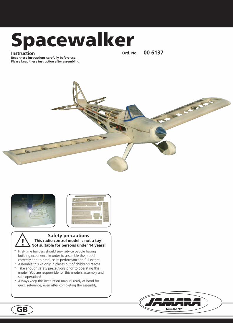
Kit Contents:• CNCLASERcutformersandribs,stripwood,selectedlight weight balsa sheet and aircraft grade plywood.• Fittingkitincludingwheels,undercarriage,hornsandhinges.• Clearcanopy.• Instructions.
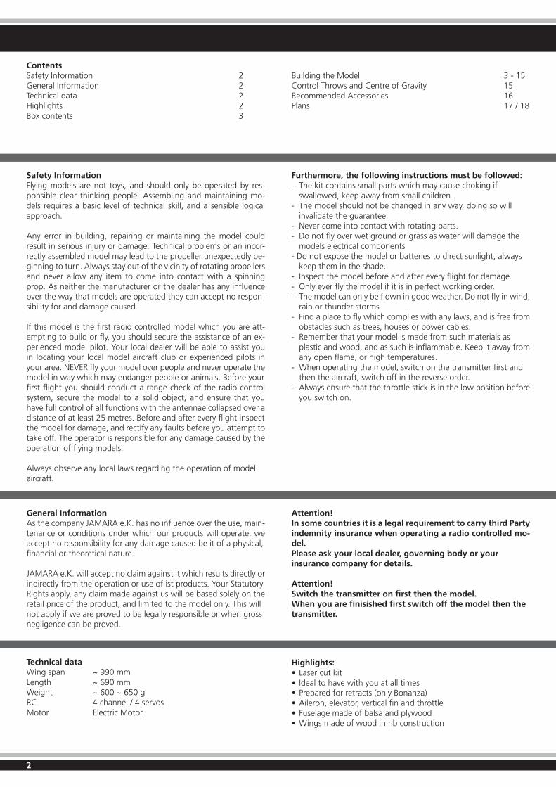
1. For the drive-in nut to have more support, the holes are doubled with a ply ring. Insert the nuts from the top and secure with a little glue.
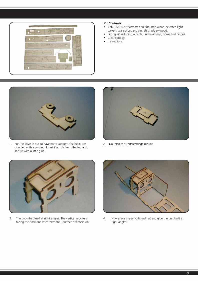
3. The two ribs glued at right angles. The vertical groove is facing the back and later takes the „surface anchors“ on.
2. Doubled the undercarriage mount.
4. Now place the servo board flat and glue the unit built at right angles.
4
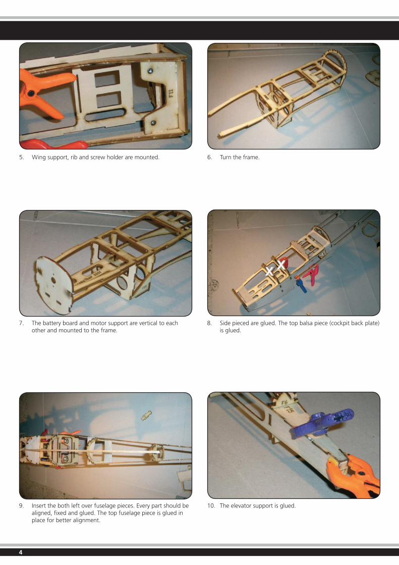
5. Wing support, rib and screw holder are mounted. 6. Turn the frame.
7. The battery board and motor support are vertical to each other and mounted to the frame.
9. Insert the both left over fuselage pieces. Every part should be aligned, fixed and glued. The top fuselage piece is glued in place for better alignment.
8. Sidepiecedareglued.Thetopbalsapiece(cockpitbackplate) is glued.
10. The elevator support is glued.
5
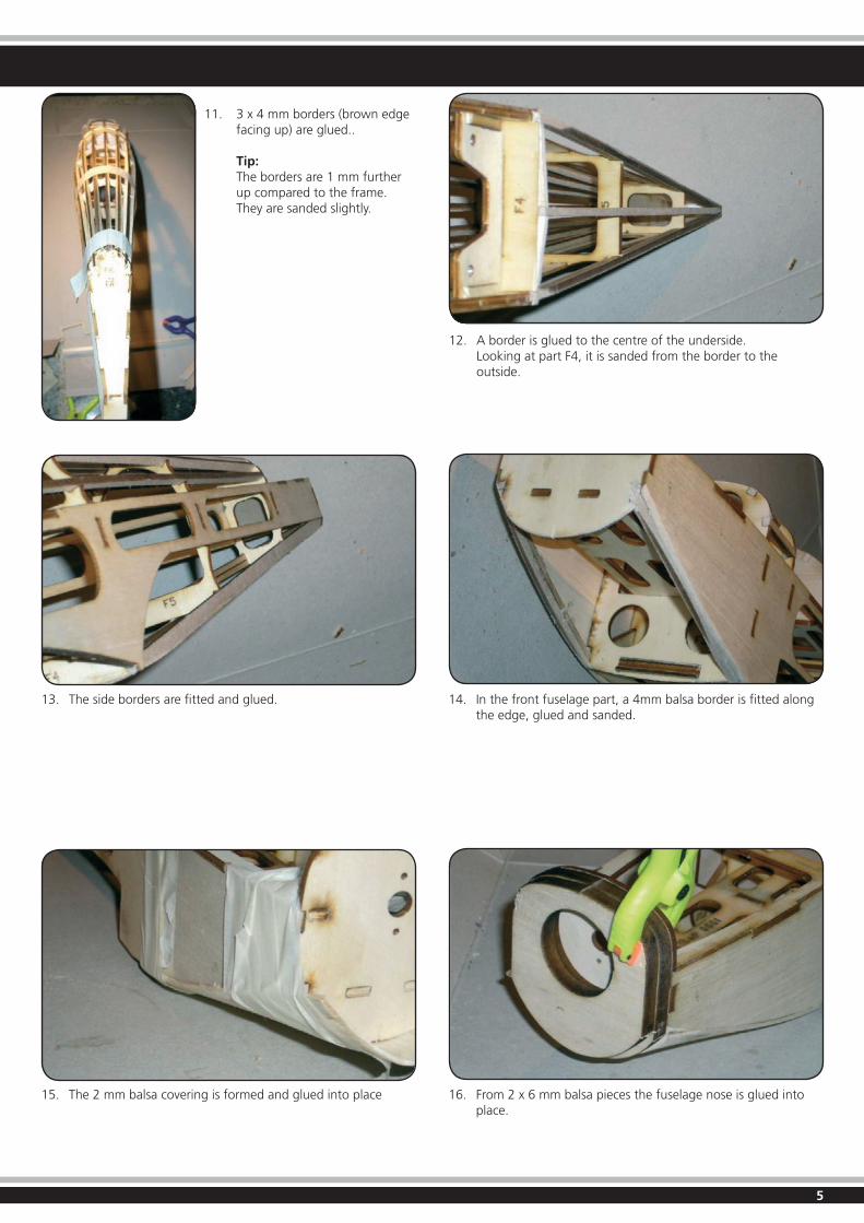
11. 3x4mmborders(brownedge facingup)areglued..
Tip: The borders are 1 mm further up compared to the frame. They are sanded slightly.
12. A border is glued to the centre of the underside. Looking at part F4, it is sanded from the border to the outside.
13. The side borders are fitted and glued.
15. The 2 mm balsa covering is formed and glued into place
14. In the front fuselage part, a 4mm balsa border is fitted along the edge, glued and sanded.
16. From 2 x 6 mm balsa pieces the fuselage nose is glued into place.
6
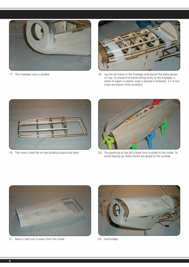
17. The fuselage nose is sanded. 18. Lay the lid frame in the fuselage and placed the balsa pieces on top. To prevent lid frame being stuck to the fuselage, a sheet of paper or plastic wrap is placed in between. 3 x 4 mm stripsaredrawn(noteposition).
19. The cover is laid flat on the building board and fixed.
21. Balsa is later put in place from the inside.
20. The planking of the lid is done from outside to the inside. To avoid tipping up, balsa sheets are glued to the outside.
22. Sand edges.
7
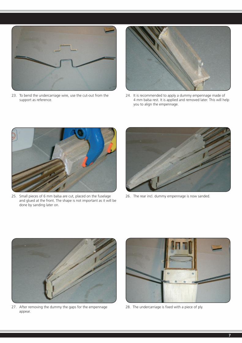
23. To bend the undercarriage wire, use the cut-out from the support as reference.
24. It is recommended to apply a dummy empennage made of 4 mm balsa rest. It is applied and removed later. This will help you to align the empennage.
25. Small pieces of 6 mm balsa are cut, placed on the fuselage and glued at the front. The shape is not important as it will be done by sanding later on.
27. After removing the dummy the gaps for the empennage appear.
26. The rear incl. dummy empennage is now sanded.
28. The undercarriage is fixed with a piece of ply.
8
Zusammenbau
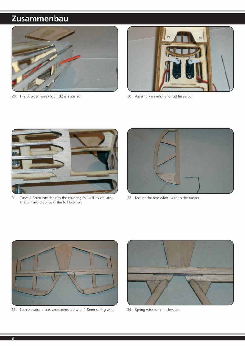
29. TheBowdenwire(notincl.)isinstalled. 30. Assembly elevator and rudder servo.
31. Carve 1,5mm into the ribs the covering foil will lay on later. This will avoid edges in the foil later on.
33. Both elevator pieces are connected with 1,5mm spring wire.
32. Mount the rear wheel wire to the rudder.
34. Spring wire sunk-in elevator.
9
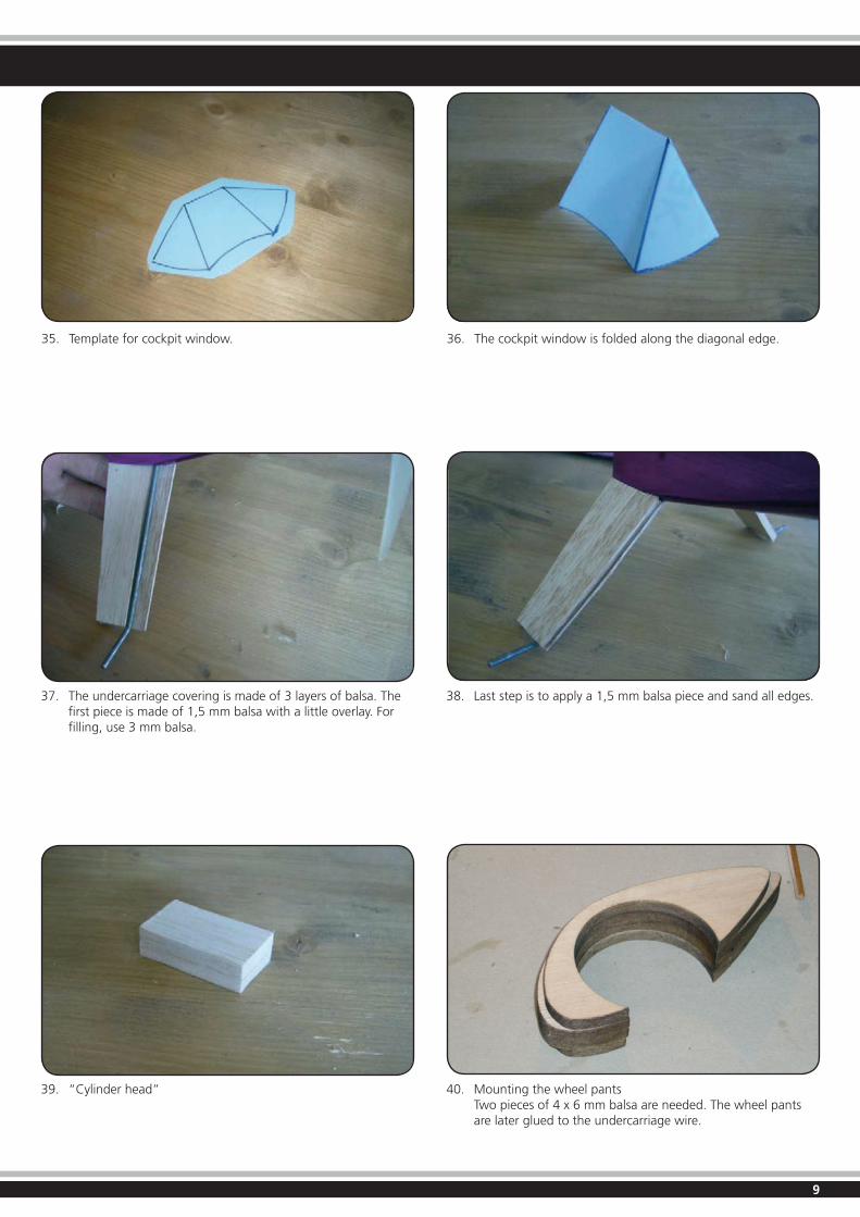
35. Template for cockpit window. 36. The cockpit window is folded along the diagonal edge.
37. The undercarriage covering is made of 3 layers of balsa. The first piece is made of 1,5 mm balsa with a little overlay. For filling, use 3 mm balsa.
39. “Cylinder head”
38. Last step is to apply a 1,5 mm balsa piece and sand all edges.
40. Mounting the wheel pants Two pieces of 4 x 6 mm balsa are needed. The wheel pants are later glued to the undercarriage wire.
10
Zusammenbau
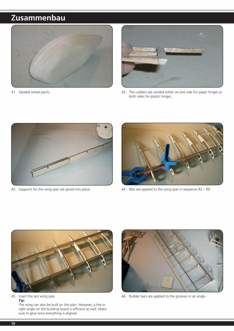
41. Sanded wheel pants. 42. The rudders are sanded either on one side for paper hinges or both sides for plastic hinges..
43. Supports for the wing spar are glued into place.
45. Insert the last wing spar. Tip: The wing can also be built on the plan. However, a line in right angle on the building board is efficient as well. Make sure to glue once everything is aligned.
44. Ribs are applied to the wing spar in sequence R2 – R9.
46. Rudder bars are applied to the grooves in an angle..
11
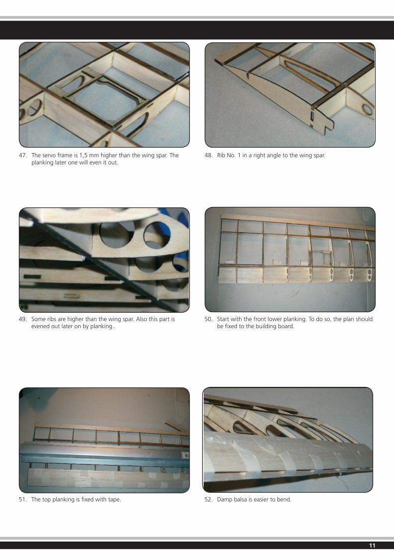
47. The servo frame is 1,5 mm higher than the wing spar. The planking later one will even it out.
48. Rib No. 1 in a right angle to the wing spar.
49. Some ribs are higher than the wing spar. Also this part is evened out later on by planking..
51. The top planking is fixed with tape.
50. Start with the front lower planking. To do so, the plan should be fixed to the building board.
52. Damp balsa is easier to bend.
12
Zusammenbau
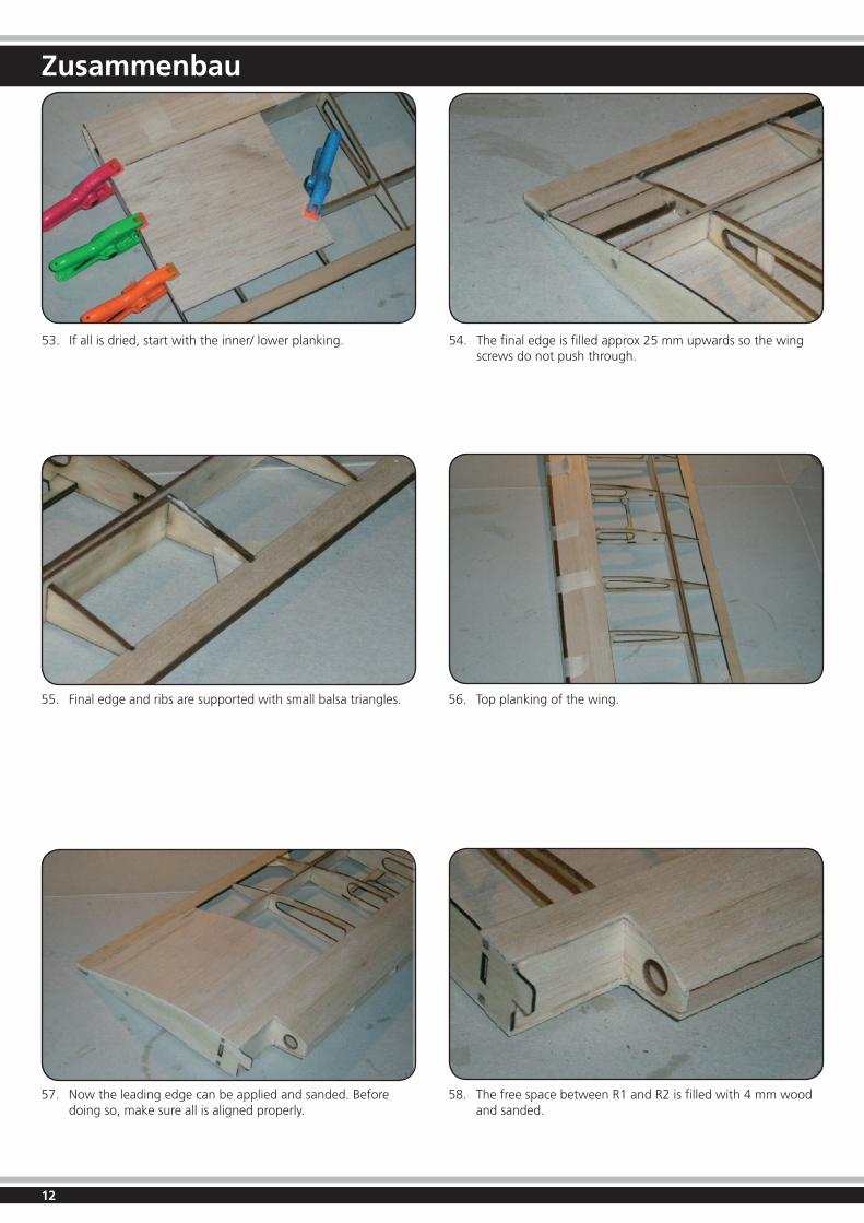
53. If all is dried, start with the inner/ lower planking. 54. The final edge is filled approx 25 mm upwards so the wing screws do not push through.
55. Final edge and ribs are supported with small balsa triangles.
57. Now the leading edge can be applied and sanded. Before doing so, make sure all is aligned properly.
56. Top planking of the wing.
58. The free space between R1 and R2 is filled with 4 mm wood and sanded.
13
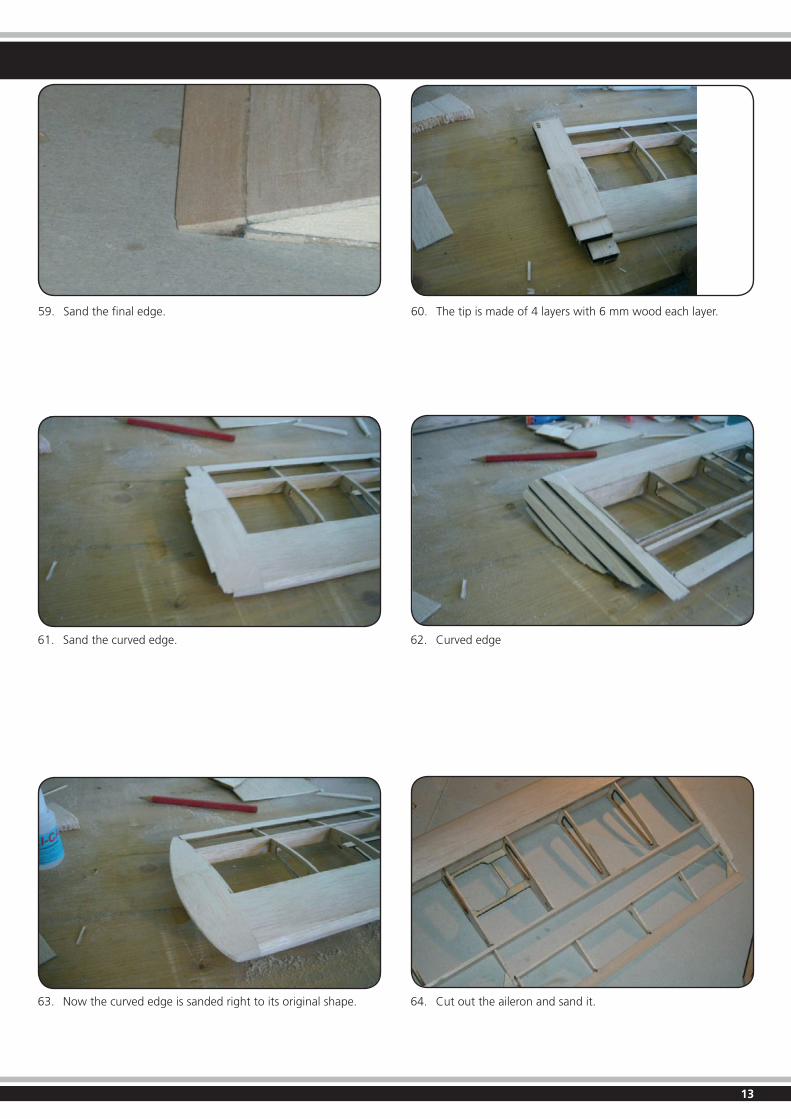
59. Sand the final edge. 60. The tip is made of 4 layers with 6 mm wood each layer.
61. Sand the curved edge.
63. Now the curved edge is sanded right to its original shape.
62. Curved edge
64. Cut out the aileron and sand it.
14
Zusammenbau
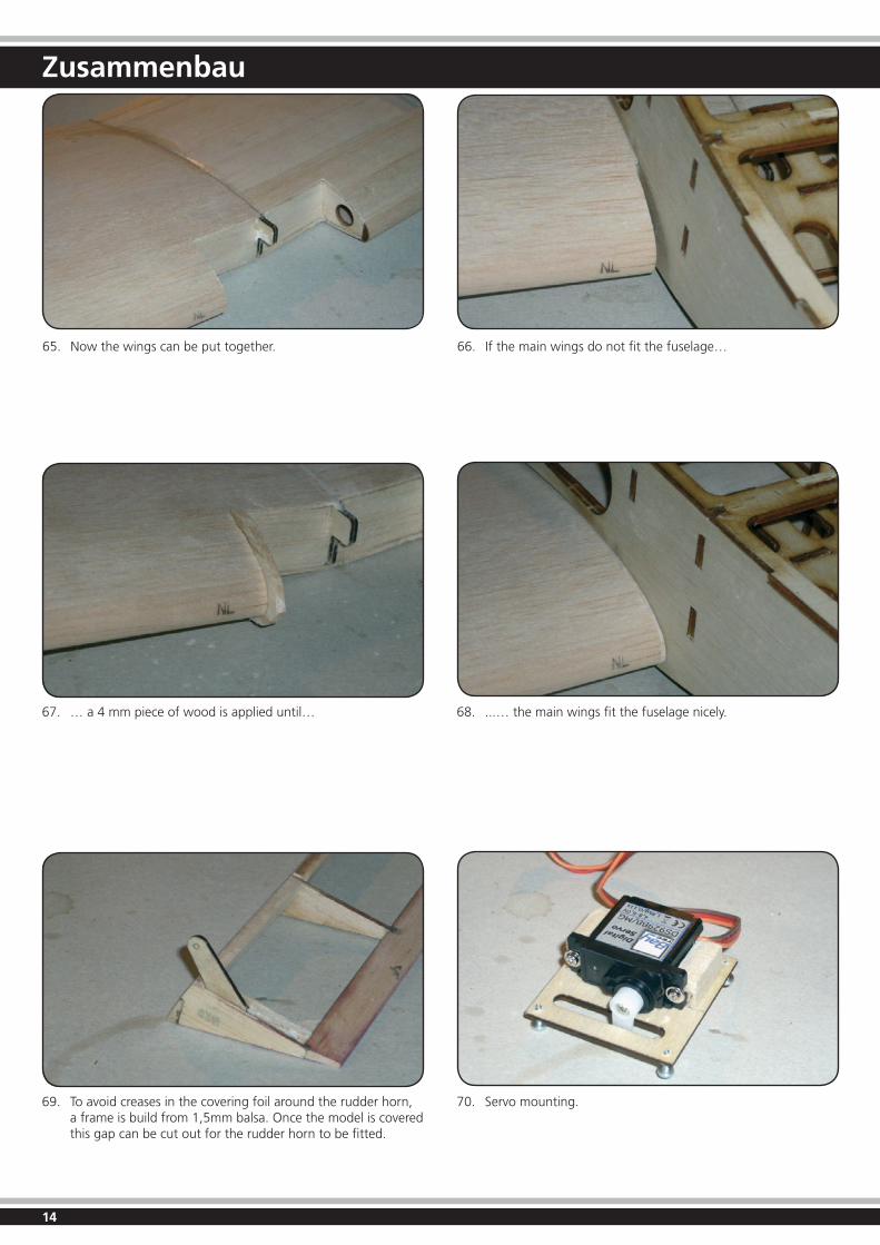
65. Now the wings can be put together. 66. If the main wings do not fit the fuselage…
67. … a 4 mm piece of wood is applied until…
69. To avoid creases in the covering foil around the rudder horn, a frame is build from 1,5mm balsa. Once the model is covered this gap can be cut out for the rudder horn to be fitted.
68. ...… the main wings fit the fuselage nicely.
70. Servo mounting.
15
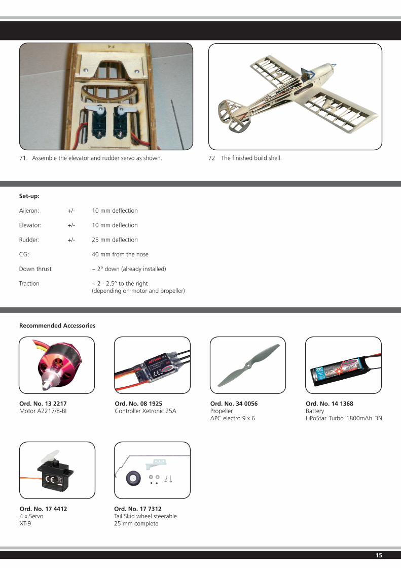
71. Assemble the elevator and rudder servo as shown. 72 The finished build shell.
Set-up:
Aileron: +/- 10 mm deflection
Elevator: +/- 10 mm deflection
Rudder: +/- 25 mm deflection
CG: 40 mm from the nose
Downthrust ~2°down(alreadyinstalled)
Traction ~ 2 - 2,5° to the right (dependingonmotorandpropeller)
Recommended Accessories
Ord. No. 13 2217Motor A2217/8-BI
Ord. No. 14 1368Battery LiPoStar Turbo 1800mAh 3N
Ord. No. 17 44124 x ServoXT-9
Ord. No. 08 1925Controller Xetronic 25A
Ord. No. 34 0056PropellerAPC electro 9 x 6
Ord. No. 17 7312Tail Skid wheel steerable25 mm complete
16
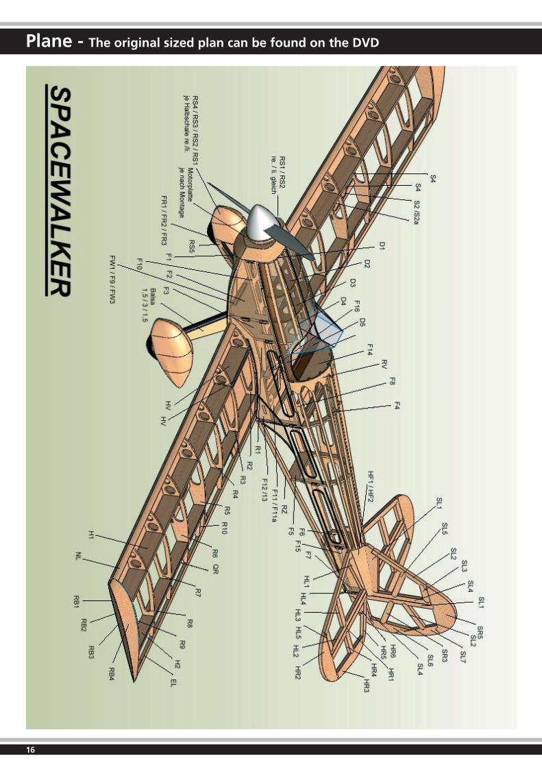
Plane - The original sized plan can be found on the DVD
17
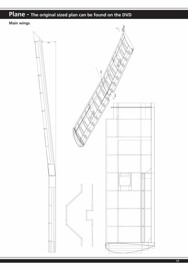
Plane - The original sized plan can be found on the DVD
48
+3m
mun
terle
gen
0mm
0mm
0mm
Main wings

40 2°
CG
2°
SP
AC
EW
ALK
ER
I
18
Plane - The original sized plan can be found on the DVD
Fuselage

19
All rights reserved.Copyright JAMARA e.K. 2011Copying or reproduction in whole or part,only with the expressed permission of JAMARA e.K.
JAMARA e.K.Inh. Erich NattererAm Lauerbühl 5 - DE-88317 AichstettenTel. +49 (0) 75 65/94 12-0 - Fax +49 (0) 75 65/94 12-23
[email protected] www.jamara.com
Order the current catalogue with our complete assortment of modelling goods today.
Name _______________________________
First name _______________________________
Street _______________________________
City _______________________________
Phone _______________________________
E-mail _______________________________
Please send the catalogue to the following speci-alist dealer:
Your dealer
______________________________________________
______________________________________________
______________________________________________
______________________________________________
We will include a catalogue for your attention with the next order of the specialist dealer.
You can receive up-to-date news through our news-letter. If you are interested, plese apply for the Jama-ra Newsletter.
Your E-mail-Address
_________________________________________________
Coupon
Newsletter