Embed Size (px)
Citation preview
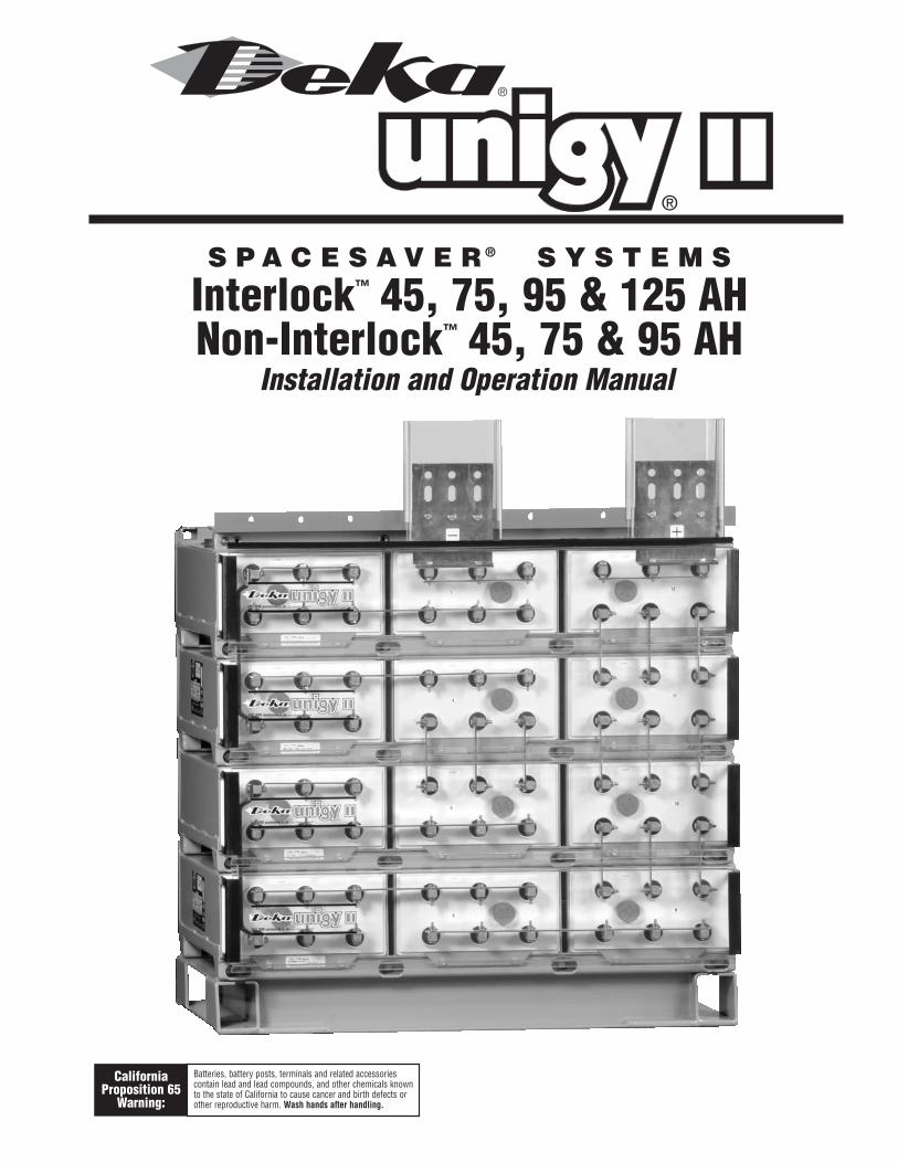
S P A C E S A V E R ® S Y S T E M S
Interlock™ 45, 75, 95 & 125 AHNon-Interlock™ 45, 75 & 95 AH
Installation and Operation Manual
®
CaliforniaProposition 65
Warning:
Batteries, battery posts, terminals and related accessoriescontain lead and lead compounds, and other chemicals knownto the state of California to cause cancer and birth defects orother reproductive harm. Wash hands after handling.
Safety PrecautionsProtective Equipment ......................................3Procedures ......................................................3
Receiving & StorageReceiving Inspection........................................3Unpacking ........................................................3Storage ............................................................3
Installation
General ............................................................3Grounding ........................................................4Electric Code for Maintenance Access ............4Floor Anchoring & Module Arrangements ......4Module Installations ........................................4
Electrical ConnectionConnector Assembly........................................4Terminal Assembly ..........................................4Final Assembly Check Procedure ......................5Parallel Strings ................................................5Module Front Shield Assembly ........................5Top Protective Shield Assembly ......................5Terminal Plate Shield Assembly ......................5
System OperationsCharger Voltage ..............................................6Operating Temperatures ................................6Cell Voltage ......................................................6Equalizing ........................................................6
TABLE OF CONTENTS
Record KeepingVoltages, Temperatures& Ohmic Readings ..........................................6
MaintenanceAnnual Inspection ........................................6-7Rectifier Ripple Voltage....................................7Battery Cleaning ..............................................7Capacity Testing ..............................................7
Cell Removal Procedure ..................................7
FIGURES ......................................................7-17
APPENDIX AMaterial Safety Data Sheet ....................18-19
APPENDIX B
Material Safety Data Sheet ....................20-21
APPENDIX CBattery Maintenance Report ......................22
APPENDIX DUNIGY II SPACESAVER® SystemAcid Volumes &Weights ............................23
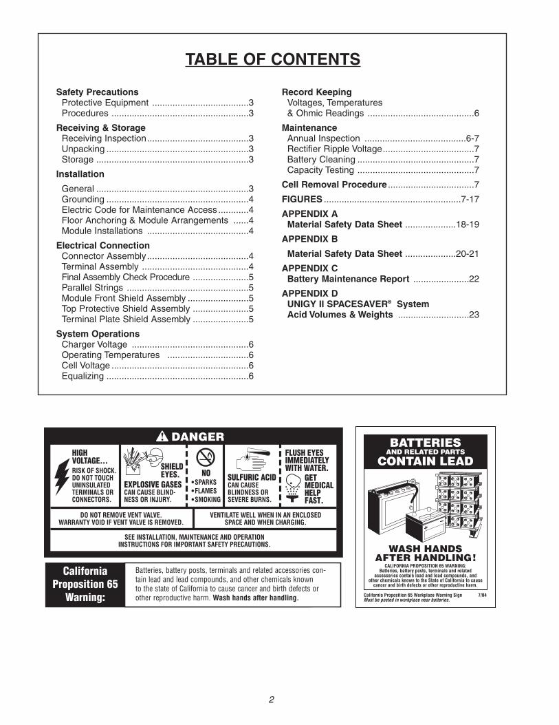
FLUSH EYESIMMEDIATELYWITH WATER.
GETMEDICALHELPFAST.
SULFURIC ACIDCAN CAUSEBLINDNESS ORSEVERE BURNS.
NO•SPARKS•FLAMES•SMOKING
SHIELDEYES.
EXPLOSIVE GASESCAN CAUSE BLIND-NESS OR INJURY.
HIGHVOLTAGE...RISK OF SHOCK.DO NOT TOUCHUNINSULATEDTERMINALS ORCONNECTORS.
DO NOT REMOVE VENT VALVE.WARRANTY VOID IF VENT VALVE IS REMOVED.
VENTILATE WELL WHEN IN AN ENCLOSEDSPACE AND WHEN CHARGING.
SEE INSTALLATION, MAINTENANCE AND OPERATIONINSTRUCTIONS FOR IMPORTANT SAFETY PRECAUTIONS.
DANGER BATTERIESAND RELATED PARTS
CONTAIN LEAD
California Proposition 65 Workplace Warning Sign 7/04Must be posted in workplace near batteries.
WASH HANDSAFTER HANDLING!
CALIFORNIA PROPOSITION 65 WARNING:Batteries, battery posts, terminals and related
accessories contain lead and lead compounds, andother chemicals known to the State of California to cause
cancer and birth defects or other reproductive harm.
CaliforniaProposition 65
Warning:
Batteries, battery posts, terminals and related accessories con-tain lead and lead compounds, and other chemicals knownto the state of California to cause cancer and birth defects orother reproductive harm. Wash hands after handling.
2
SAFETY PRECAUTIONSAlthough all valve-regulated batteries have the electrolyteimmobilized within the cell, the electrical hazard associatedwith batteries still exists. Work performed on thesebatteries should be done with the tools and the protectiveequipment listed below. Valve-regulated battery installationsshould be supervised by personnel familiar with batteriesand battery safety precautions.
Protective EquipmentTo assure safe battery handling, installation andmaintenance, the following protective equipment shouldbe used:1. Safety glasses or face shield2. Acid-resistant gloves3. Protective aprons and safety shoes4. Proper lifting devices5. Properly insulated tools
ProceduresThe following safety procedures should be followed duringinstallation: (Always wear safety glasses or face shieldwhen working on or near batteries. Refer to Fig. 1-1, pg. 3)1. These batteries are sealed and contain no free electrolyte.Under normal operating conditions, they do not presentany acid danger. However, if the battery jar or cover isdamaged, acid could be present. Sulfuric acid is harmfulto the skin and eyes. Flush affected area with waterimmediately and consult a physician if splashed in theeyes.
2. Prohibit smoking and open flames, and avoid arcing inthe immediate vicinity of the battery.
3. Do not wear metallic objects, such as jewelry, whileworking on batteries.
4. Keep the top of the battery dry and clear of all tools andother foreign objects.
5. Provide adequate ventilation (per IEEE standard 1187and/or local codes) and follow recommended chargingvoltages.
6. Extinguishing media: Class ABC extinguisher.Note: CO2 may be used but not directly on the cellsdue to thermal shock and potential cracking of cases.
7. Never remove or tamper with the pressure relief valves.Warranty void if vent valve is removed.
8. Inspect all flooring and lifting equipment for functionaladequacy.
9. Adequately secure battery modules, racks, or cabinetsto the floor.
10. Connect support structures to ground system inaccordance with applicable codes.
RECEIVING & STORAGEReceiving InspectionUpon receipt, and at the time of actual unloading, eachpackage should be visually inspected for any possibledamage or electrolyte leakage. If either is evident, a moredetailed inspection of the entire shipment should beconducted and noted on the bill of lading. Record receiptdate, inspection data and notify the carrier of any damage.
Unpacking1. Always wear eye protection.2. Check all batteries for visible defects such as crackedcontainers, looser terminal posts, or other unrepairableproblems. Batteries with these defects must be replaced.
3. Check the contents of the package against the packaginglist. Report any missing parts or shipping damage toyour East Penn agent or East Penn Mfg. Co. immediately.(See Fig. 2-1, pg. 8.)
4. Never lift the batteries by the terminal posts.(See Fig. 3-1, pg. 8.)
5. When lifting batteries, the proper equipment is neededsuch as a forklift or a portable crane. Always check thelifting capacities of the equipment being used and neverlift more than one module at a time by the modulemounting holes.
Storage1. Cells should be stored indoors in a clean, level, dry andcool location. Recommended storage temperature is0˚F to 90˚F (–18˚C to 32˚C).
2. Stored lead-acid batteries self discharge and must begiven a boost charge six months from the date ofmanufacture to prevent permanent performancedegradation. Record dates and conditions for allcharges during storage.
3. Do not store beyond 12 months.4. Store in horizontal position only.
INSTALLATIONGeneralCaution should be taken when installing batteries to insureno damage occurs. The battery cabinet, tray, rack, etc. shallbe inspected for sharp edges that could cause damage to thebattery casing. Batteries shall not be dropped, slid, or placedon rough or uneven surfaces such as tray lips or gratedflooring. Mishandling of batteries could result in equipmentdamage or human injury. East Penn will not be liable fordamage or injury as a result of mishandling or misuse of theproduct.
DANGERSHIELDEYES.
EXPLOSIVEGASES CAN CAUSE
BLINDNESS OR INJURY.
HIGH VOLTAGE...RISK OF SHOCK.DO NOT TOUCHUNINSULATEDTERMINALS ORCONNECTORS.
VENTILATE WELL WHEN IN AN ENCLOSEDSPACE AND WHEN CHARGING.
SEE INSTALLATION, MAINTENANCE AND OPERATIONINSTRUCTIONS FOR IMPORTANT SAFETY PRECAUTIONS.
NO•SPARKS•FLAMES•SMOKING
SULFURICACIDCANCAUSEBLINDNESS ORSEVERE BURNS.
FLUSH EYESIMMEDIATELYWITH WATER.
GETMEDICALHELPFAST.
DO NOT REMOVE VENT VALVE.WARRANTY VOID IF VENT VALVE IS REMOVED.
Fig. 1-1
CaliforniaProposition 65
Warning:
Batteries, battery posts, terminals and related accessoriescontain lead and lead compounds, and other chemicals knownto the state of California to cause cancer and birth defects orother reproductive harm. Wash hands after handling.
3
INSTALLATION (con’t)
GroundingWhen grounding the battery system, proper techniquesshould be applied per electrical standards, such as NECand/or local codes.Two .201 diameter x .750 center holes are provided in backof each module to accept a #6 x .750 center compressiongrounding lug. The holes must be tapped for a 1/4-20UNCthread and paint must be removed for a proper groundingpad location.
Electric Code for Maintenance AccessRefer to ANSI/NFPA-70 National Electric Code for accessand working space requirements around the battery.A minimum of 36" aisle space is recommended in frontof the battery for service and inspection.**Note: Battery system and/or individual module grounding, if required, isthe installer’s responsibility.
Floor Anchoring & Module ArrangementsSee East Penn Mfg. Co.’s schematic diagram illustration.One is supplied with each shipment. If it cannot be located,contact East Penn Mfg. Co. for a copy. Refer to your deliverynumber, located on the packing slip. This will aid in obtainingthe proper drawing.
Module InstallationsAssemble modules per the following details.CAUTION: Never lift more than one module at a time withthe lifting slings. (See Fig. 3-2, pg. 9.)1. UBC Zone 4 hardware included for Interlock™ moduleassembly (45, 75 & 95 AH). (See Fig. 3-4, pg. 10)
2. Unbolt the floor-mounting channel from the top of thebattery.
3. Use the two slings provided to lift modules.Note: For Interlock™ module lift the top module slightlyand slide front. (This will release the interlock tabs andwill free itself from the remaining stack.)(See Fig. 3-2, pg. 9)
4. For the Non-Interlock modules, reference figure 3.5,pg. 11 for marking hole locations to mount basesupports to floor. For the Interlock modules, use 1-piecebase for marking floor hole location. (See local buildingcodes for anchor bolt requirements, anchor bolts notincluded.)
5. Remove the next module in the same manner as the first.Place in position.Note: For Interlock™ module slide back allowing thetabs to lock in place. (No rear bolts required)(See Fig. 3-2, pg. 9)
6. Each battery is shipped with its own schematic. Makesure the polarity on the batteries match the drawings.
ELECTRICAL CONNECTIONConnector Assembly1. The contact surfaces of each individual post on everycell have been cleaned and coated with a thin film ofno-ox-ID “A” grease at the factory. Assure the contactsurfaces are free of dust or dirt prior to assembly.
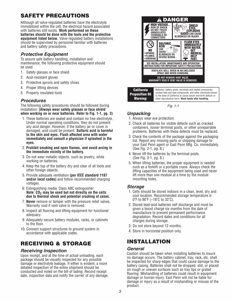
2. The Interlock™ and Non-Interlock™ battery (45, 75 &95 AH) are supplied with connector package “1CU”requiring one connector per post. Install the connectorsloosely to allow for final alignment, then torque to
Connector Assembly (con’t)125 ± 5 inch pounds (14.1 ± .5 Nm.) The installationand direction of the post bolts is important! (Refer toFig. 4-1, 4-2 and 4-3 pg. 11 and 12; Fig. 4-4, pg. 4.For proper direction when inserting into posts.) The125 AH battery is supplied with a 2CU connectorpackage as standard. (Refer to Fig.5-1A, pg. 13 forspecial connector orientation for side terminal & stackto stack connections.)
3. Batteries used in high rate discharge applications requiremultiple connectors per connection. (Refer to optionalconnector packages in Fig. 4-5, pg. 4)
Terminal Assembly1. Attach the terminal mounting bracket to the moduleframe. (See Fig. 5-1, pg. 13 for Interlock™ and Fig. 5-2and 5-2A for Non-Interlock™, pg. 14 for Side Terminal;See Fig. 5-3 and Fig. 5-3A, pg. 15 for Top Terminal)
2. Attach the terminal plates or the terminal connectorsto the battery posts and then torque to 125 ± 5 inch-pounds (14.1 ± .5 Nm). (See Fig. 5-3 and Fig. 5-3A,pg. 15 for 95 AH vs. 125 AH)
3. For cable connection assembly, (See Fig. 7-1, pg. 16and Fig. 7-1A, pg. 17.)
Fig. 4-4
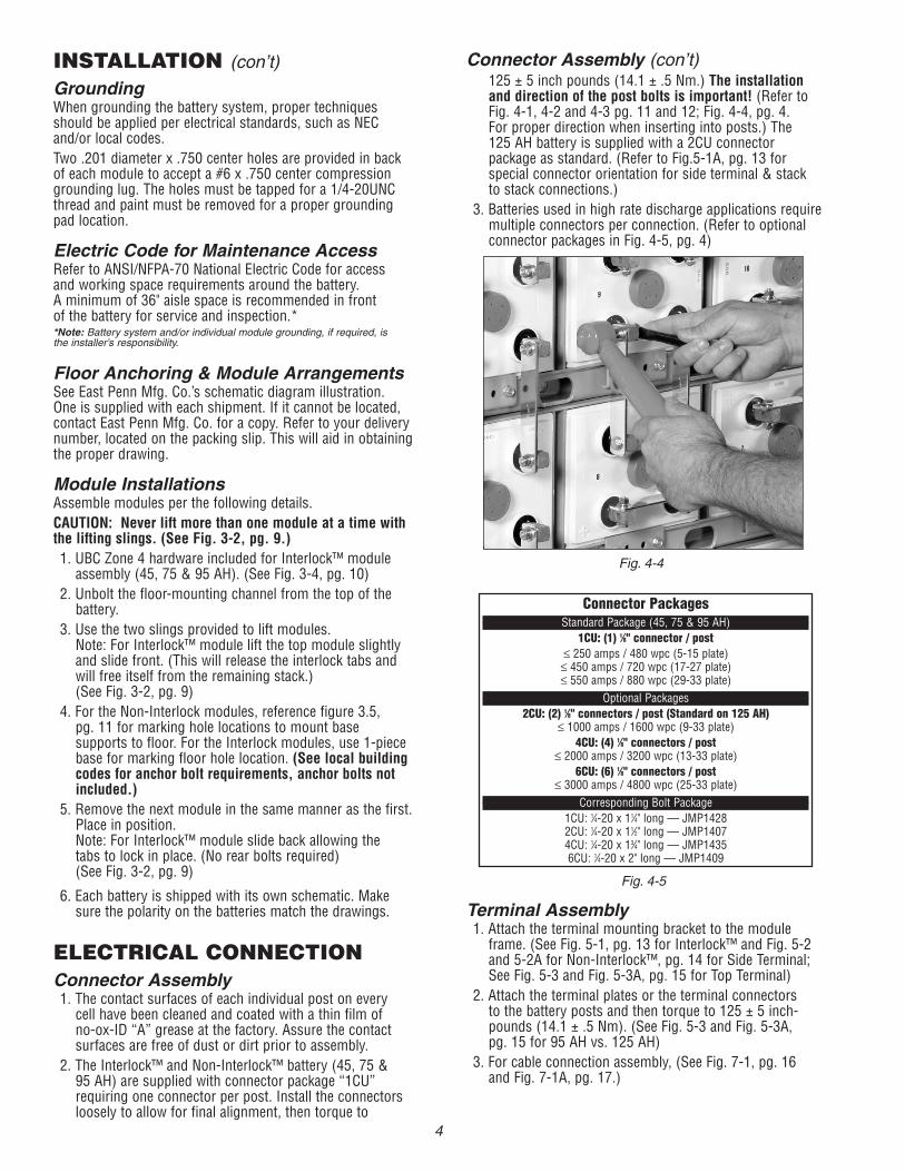
Connector PackagesStandard Package (45, 75 & 95 AH)
1CU: (1) 1⁄8" connector / post≤ 250 amps / 480 wpc (5-15 plate)≤ 450 amps / 720 wpc (17-27 plate)≤ 550 amps / 880 wpc (29-33 plate)
Optional Packages2CU: (2) 1⁄8" connectors / post (Standard on 125 AH)
≤ 1000 amps / 1600 wpc (9-33 plate)4CU: (4) 1⁄8" connectors / post
≤ 2000 amps / 3200 wpc (13-33 plate)6CU: (6) 1⁄8" connectors / post
≤ 3000 amps / 4800 wpc (25-33 plate)Corresponding Bolt Package
1CU: 1⁄4-20 x 11⁄4" long — JMP14282CU: 1⁄4-20 x 11⁄2" long — JMP14074CU: 1⁄4-20 x 13⁄4" long — JMP14356CU: 1⁄4-20 x 2" long — JMP1409
Fig. 4-5
4
Final Assembly Check Procedure1. For future identification of all cells, number individualcells in sequence, beginning with number one (1) at thepositive end of the battery. The last cell of the battery islocated at the negative output terminal.
2. Read and record the voltages of the individual cells toassure that they are connected properly. The total batteryvoltage should be approximately equal to the number ofcells connected in series multiplied by the measuredvoltage of one cell. If the measurement is less, recheckthe connections for proper polarity. Verify that all cell andbattery connections have been properly torqued.
3. Measure and record the intercell connection resistanceusing a micro-ohms meter. This helps determine theadequacy of initial connection installation and can beused as a reference for future maintenance requirements.Refer to the recording forms in Appendix C of thismanual. Review the records of each connection anddetail resistance measurements. Clean, remake, andremeasure any connection that has a resistancemeasurement greater than 10% of the average of all thesame type connections (i.e. intercell, intermodule, etc.).
4. Battery performance is based on the output at the batteryterminals. Therefore, the shortest electrical connectionbetween the battery system and the operating equipmentresults in maximum total system performance.
Select cable size based on current carrying capability andvoltage drop.Cable size should not provide a greater voltage drop betweenthe battery system and operating equipment than specified.Excessive voltage drop in cables will reduce the desiredreserve time and power from the battery system.
Parallel StringsWhen paralleling valve-regulated batteries, the capacity,arrangement, and external circuit length should be identicalfor each battery. Wide variation in the battery circuitresistance can result in unbalanced charging (i.e., excessivecharging currents in some batteries and undercharging inothers). As a result, cell failures in one battery string andsubsequent loss of performance capabilities of that stringwill result in higher loads in the other parallel string(s),which may exceed the ratings of the battery connections.This can damage the battery system and dramaticallyshorten battery life.
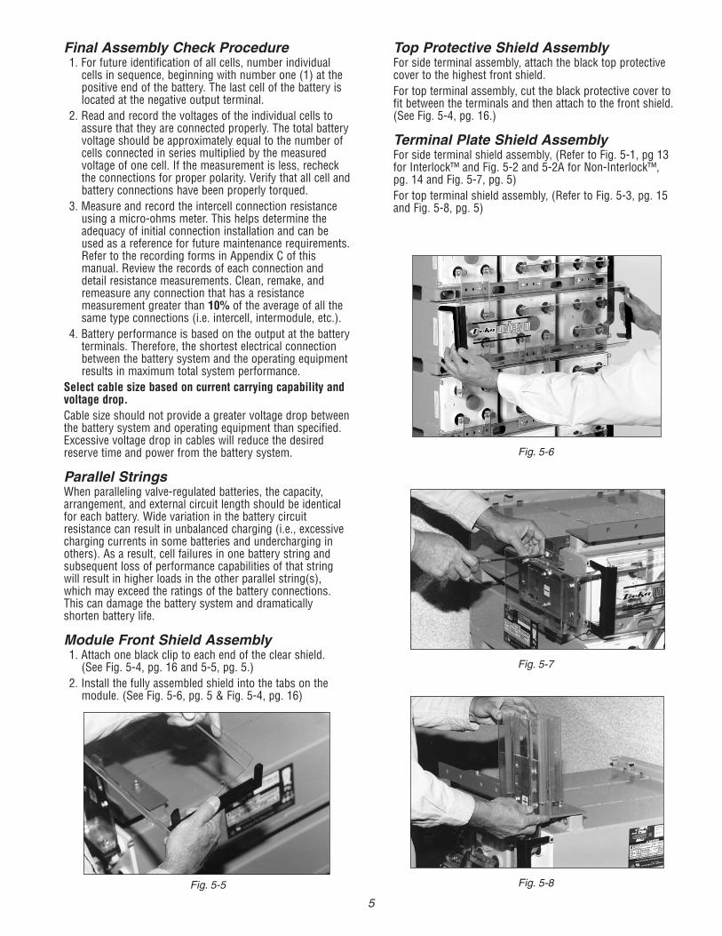
Module Front Shield Assembly1. Attach one black clip to each end of the clear shield.(See Fig. 5-4, pg. 16 and 5-5, pg. 5.)
2. Install the fully assembled shield into the tabs on themodule. (See Fig. 5-6, pg. 5 & Fig. 5-4, pg. 16)
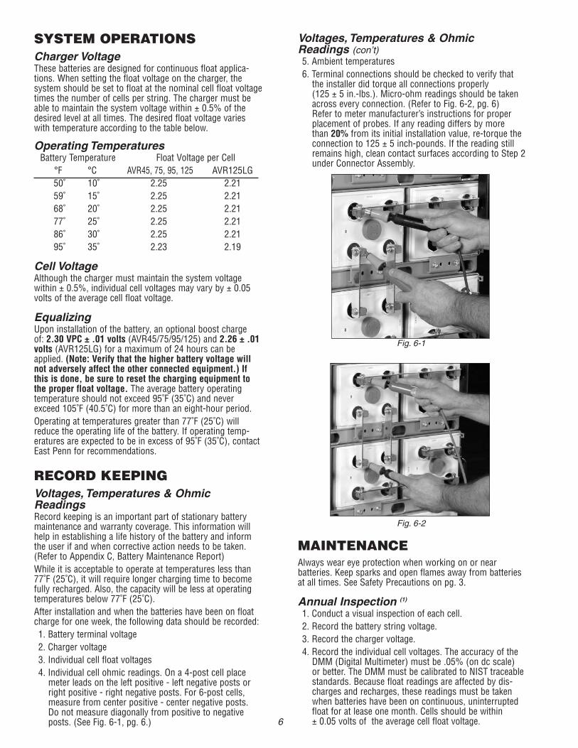
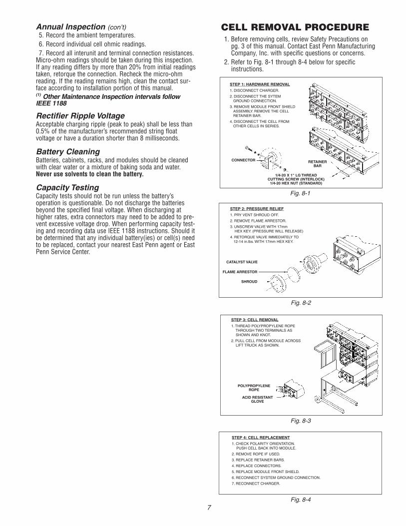
Top Protective Shield AssemblyFor side terminal assembly, attach the black top protectivecover to the highest front shield.For top terminal assembly, cut the black protective cover tofit between the terminals and then attach to the front shield.(See Fig. 5-4, pg. 16.)
Terminal Plate Shield AssemblyFor side terminal shield assembly, (Refer to Fig. 5-1, pg 13for Interlock™ and Fig. 5-2 and 5-2A for Non-Interlock™,pg. 14 and Fig. 5-7, pg. 5)For top terminal shield assembly, (Refer to Fig. 5-3, pg. 15and Fig. 5-8, pg. 5)
Fig. 5-5
Fig. 5-7
Fig. 5-8
Fig. 5-6
5
Voltages, Temperatures & OhmicReadings (con’t)5. Ambient temperatures6. Terminal connections should be checked to verify thatthe installer did torque all connections properly(125 ± 5 in.-lbs.). Micro-ohm readings should be takenacross every connection. (Refer to Fig. 6-2, pg. 6)Refer to meter manufacturer’s instructions for properplacement of probes. If any reading differs by morethan 20% from its initial installation value, re-torque theconnection to 125 ± 5 inch-pounds. If the reading stillremains high, clean contact surfaces according to Step 2under Connector Assembly.
MAINTENANCEAlways wear eye protection when working on or nearbatteries. Keep sparks and open flames away from batteriesat all times. See Safety Precautions on pg. 3.
Annual Inspection (1)
1. Conduct a visual inspection of each cell.2. Record the battery string voltage.3. Record the charger voltage.4. Record the individual cell voltages. The accuracy of theDMM (Digital Multimeter) must be .05% (on dc scale)or better. The DMM must be calibrated to NIST traceablestandards. Because float readings are affected by dis-charges and recharges, these readings must be takenwhen batteries have been on continuous, uninterruptedfloat for at lease one month. Cells should be within± 0.05 volts of the average cell float voltage.
SYSTEM OPERATIONSCharger VoltageThese batteries are designed for continuous float applica-tions. When setting the float voltage on the charger, thesystem should be set to float at the nominal cell float voltagetimes the number of cells per string. The charger must beable to maintain the system voltage within ± 0.5% of thedesired level at all times. The desired float voltage varieswith temperature according to the table below.
Operating TemperaturesBattery Temperature Float Voltage per Cell
°F °C AVR45, 75, 95, 125 AVR125LG50˚ 10˚ 2.25 2.2159˚ 15˚ 2.25 2.2168˚ 20˚ 2.25 2.2177˚ 25˚ 2.25 2.2186˚ 30˚ 2.25 2.2195˚ 35˚ 2.23 2.19
Cell VoltageAlthough the charger must maintain the system voltagewithin ± 0.5%, individual cell voltages may vary by ± 0.05volts of the average cell float voltage.
EqualizingUpon installation of the battery, an optional boost chargeof: 2.30 VPC ± .01 volts (AVR45/75/95/125) and 2.26 ± .01volts (AVR125LG) for a maximum of 24 hours can beapplied. (Note: Verify that the higher battery voltage willnot adversely affect the other connected equipment.) Ifthis is done, be sure to reset the charging equipment tothe proper float voltage. The average battery operatingtemperature should not exceed 95˚F (35˚C) and neverexceed 105˚F (40.5˚C) for more than an eight-hour period.Operating at temperatures greater than 77˚F (25˚C) willreduce the operating life of the battery. If operating temp-eratures are expected to be in excess of 95˚F (35˚C), contactEast Penn for recommendations.
RECORD KEEPINGVoltages, Temperatures & OhmicReadingsRecord keeping is an important part of stationary batterymaintenance and warranty coverage. This information willhelp in establishing a life history of the battery and informthe user if and when corrective action needs to be taken.(Refer to Appendix C, Battery Maintenance Report)While it is acceptable to operate at temperatures less than77˚F (25˚C), it will require longer charging time to becomefully recharged. Also, the capacity will be less at operatingtemperatures below 77˚F (25˚C).After installation and when the batteries have been on floatcharge for one week, the following data should be recorded:1. Battery terminal voltage2. Charger voltage3. Individual cell float voltages4. Individual cell ohmic readings. On a 4-post cell placemeter leads on the left positive - left negative posts orright positive - right negative posts. For 6-post cells,measure from center positive - center negative posts.Do not measure diagonally from positive to negativeposts. (See Fig. 6-1, pg. 6.)
Fig. 6-1
Fig. 6-2
6
Annual Inspection (con’t)5. Record the ambient temperatures.6. Record individual cell ohmic readings.7. Record all interunit and terminal connection resistances.Micro-ohm readings should be taken during this inspection.If any reading differs by more than 20% from initial readingstaken, retorque the connection. Recheck the micro-ohmreading. If the reading remains high, clean the contact sur-face according to installation portion of this manual.(1) Other Maintenance Inspection intervals followIEEE 1188
Rectifier Ripple VoltageAcceptable charging ripple (peak to peak) shall be less than0.5% of the manufacturer’s recommended string floatvoltage or have a duration shorter than 8 milliseconds.
Battery CleaningBatteries, cabinets, racks, and modules should be cleanedwith clear water or a mixture of baking soda and water.Never use solvents to clean the battery.
Capacity TestingCapacity tests should not be run unless the battery’soperation is questionable. Do not discharge the batteriesbeyond the specified final voltage. When discharging athigher rates, extra connectors may need to be added to pre-vent excessive voltage drop. When performing capacity test-ing and recording data use IEEE 1188 instructions. Should itbe determined that any individual battery(ies) or cell(s) needto be replaced, contact your nearest East Penn agent or EastPenn Service Center.
Fig. 8-4
Fig. 8-1
Fig. 8-2
Fig. 8-3
STEP 1: HARDWARE REMOVAL
1. DISCONNECT CHARGER.
2. DISCONNECT THE SYTEMGROUND CONNECTION.
3. REMOVE MODULE FRONT SHIELDASSEMBLY. REMOVE THE CELLRETAINER BAR.
4. DISCONNECT THE CELL FROMOTHER CELLS IN SERIES.
STEP 2: PRESSURE RELIEF
1. PRY VENT SHROUD OFF.
2. REMOVE FLAME ARRESTOR.
3. UNSCREW VALVE WITH 17mmHEX KEY. (PRESSURE WILL RELEASE)
4. RETORQUE VALVE IMMEDIATELY TO12-14 in.lbs. WITH 17mm HEX KEY.
STEP 3: CELL REMOVAL
1. THREAD POLYPROPYLENE ROPETHROUGH TWO TERMINALS ASSHOWN AND KNOT.
2. PULL CELL FROM MODULE ACROSSLIFT TRUCK AS SHOWN.
STEP 4: CELL REPLACEMENT
1. CHECK POLARITY ORIENTATION.PUSH CELL BACK INTO MODULE.
2. REMOVE ROPE IF USED.
3. REPLACE RETAINER BARS.
4. REPLACE CONNECTORS.
5. REPLACE MODULE FRONT SHIELD.
6. RECONNECT SYSTEM GROUND CONNECTION.
7. RECONNECT CHARGER.
CONNECTOR RETAINERBAR
1/4-20 X 1" LG THREADCUTTING SCREW (INTERLOCK)1/4-20 HEX NUT (STANDARD)
CATALYST VALVE
FLAME ARRESTOR
SHROUD
POLYPROPYLENEROPE
ACID RESISTANTGLOVE
CELL REMOVAL PROCEDURE1. Before removing cells, review Safety Precautions onpg. 3 of this manual. Contact East Penn ManufacturingCompany, Inc. with specific questions or concerns.
2. Refer to Fig. 8-1 through 8-4 below for specificinstructions.
7
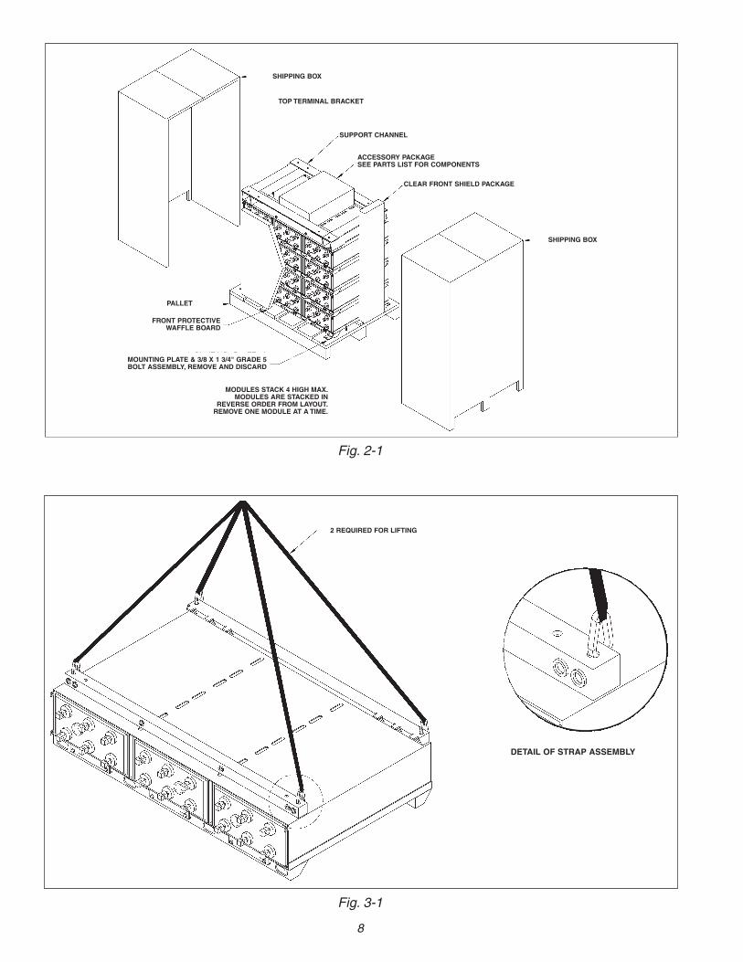
Fig. 2-1
SHIPPING BOX
TOP TERMINAL BRACKET
SUPPORT CHANNEL
ACCESSORY PACKAGESEE PARTS LIST FOR COMPONENTS
CLEAR FRONT SHIELD PACKAGE
SHIPPING BOX
PALLET
FRONT PROTECTIVEWAFFLE BOARD
MOUNTING PLATE & 3/8 X 1 3/4" GRADE 5BOLT ASSEMBLY, REMOVE AND DISCARD
MODULES STACK 4 HIGH MAX.MODULES ARE STACKED IN
REVERSE ORDER FROM LAYOUT.REMOVE ONE MODULE AT A TIME.
Fig. 3-1
2 REQUIRED FOR LIFTING
DETAIL OF STRAP ASSEMBLY
8
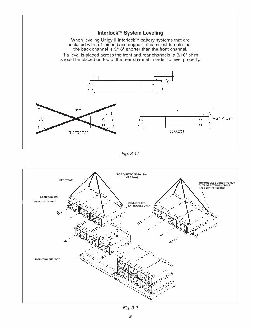
Fig. 3-1A
Fig. 3-2
JOINING PLATETOP MODULE ONLY
TOP MODULE SLIDES INTO CUTOUTS OF BOTTOM MODULE(NO BOLTING NEEDED)
TORQUE TO 50 in. lbs.(5.6 Nm)
LIFT STRAP
LOCKWASHER
3/8-16 X 1 1/4" BOLT
MOUNTING SUPPORT
Interlock™ System LevelingWhen leveling Unigy II Interlock™ battery systems that areinstalled with a 1-piece base support, it is critical to note thatthe back channel is 3/16" shorter than the front channel.
If a level is placed across the front and rear channels, a 3/16" shimshould be placed on top of the rear channel in order to level properly.
9
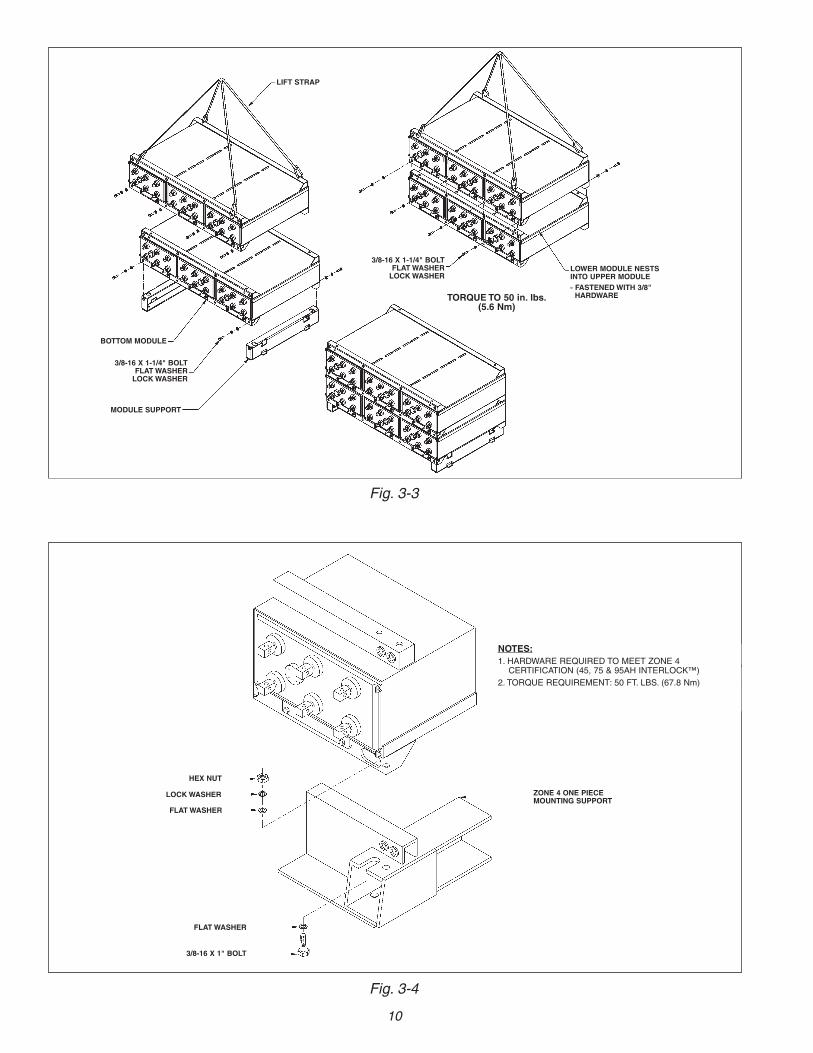
Fig. 3-3
LIFT STRAP
MODULE SUPPORT
BOTTOM MODULE
3/8-16 X 1-1/4" BOLTFLATWASHERLOCKWASHER
3/8-16 X 1-1/4" BOLTFLATWASHERLOCKWASHER
LOWER MODULE NESTSINTO UPPER MODULE- FASTENEDWITH 3/8"HARDWARETORQUE TO 50 in. lbs.
(5.6 Nm)
Fig. 3-4
HEX NUT
LOCKWASHER
FLATWASHER
FLATWASHER
3/8-16 X 1" BOLT
ZONE 4 ONE PIECEMOUNTING SUPPORT
NOTES:1. HARDWARE REQUIRED TO MEET ZONE 4CERTIFICATION (45, 75 & 95AH INTERLOCK™)
2. TORQUE REQUIREMENT: 50 FT. LBS. (67.8 Nm)
10
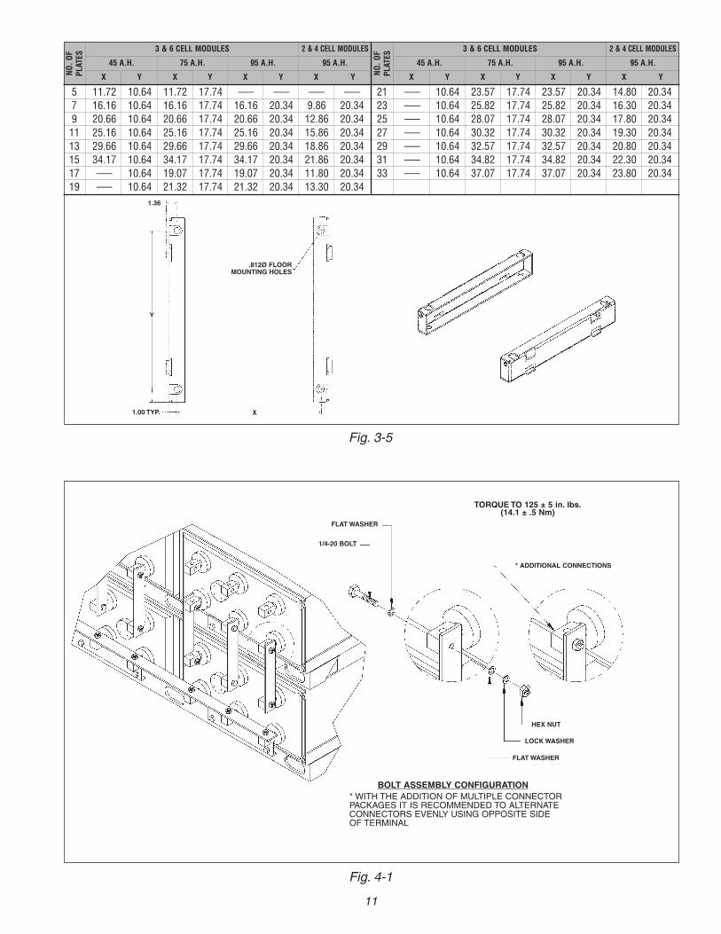
Fig. 4-1
FLATWASHER
1/4-20 BOLT
TORQUE TO 125 ± 5 in. lbs.(14.1 ± .5 Nm)
* ADDITIONAL CONNECTIONS
HEX NUT
LOCKWASHER
FLATWASHER
BOLT ASSEMBLY CONFIGURATION* WITH THE ADDITION OF MULTIPLE CONNECTORPACKAGES IT IS RECOMMENDED TO ALTERNATECONNECTORS EVENLY USING OPPOSITE SIDEOF TERMINAL
11
Fig. 3-5
5 11.72 10.64 11.72 17.74 ––– ––– ––– –––7 16.16 10.64 16.16 17.74 16.16 20.34 9.86 20.349 20.66 10.64 20.66 17.74 20.66 20.34 12.86 20.3411 25.16 10.64 25.16 17.74 25.16 20.34 15.86 20.3413 29.66 10.64 29.66 17.74 29.66 20.34 18.86 20.3415 34.17 10.64 34.17 17.74 34.17 20.34 21.86 20.3417 ––– 10.64 19.07 17.74 19.07 20.34 11.80 20.3419 ––– 10.64 21.32 17.74 21.32 20.34 13.30 20.34
21 ––– 10.64 23.57 17.74 23.57 20.34 14.80 20.3423 ––– 10.64 25.82 17.74 25.82 20.34 16.30 20.3425 ––– 10.64 28.07 17.74 28.07 20.34 17.80 20.3427 ––– 10.64 30.32 17.74 30.32 20.34 19.30 20.3429 ––– 10.64 32.57 17.74 32.57 20.34 20.80 20.3431 ––– 10.64 34.82 17.74 34.82 20.34 22.30 20.3433 ––– 10.64 37.07 17.74 37.07 20.34 23.80 20.34
NO.O
FPLATES
3 & 6 CELL MODULES
45 A.H. 75 A.H. 95 A.H.
X X XY Y Y
2 & 4 CELL MODULES
95 A.H.
X Y NO.O
FPLATES
3 & 6 CELL MODULES
45 A.H. 75 A.H. 95 A.H.
X X XY Y Y
2 & 4 CELL MODULES
95 A.H.
X Y
.812Ø FLOORMOUNTING HOLES
1.00 TYP. X
Y
1.36
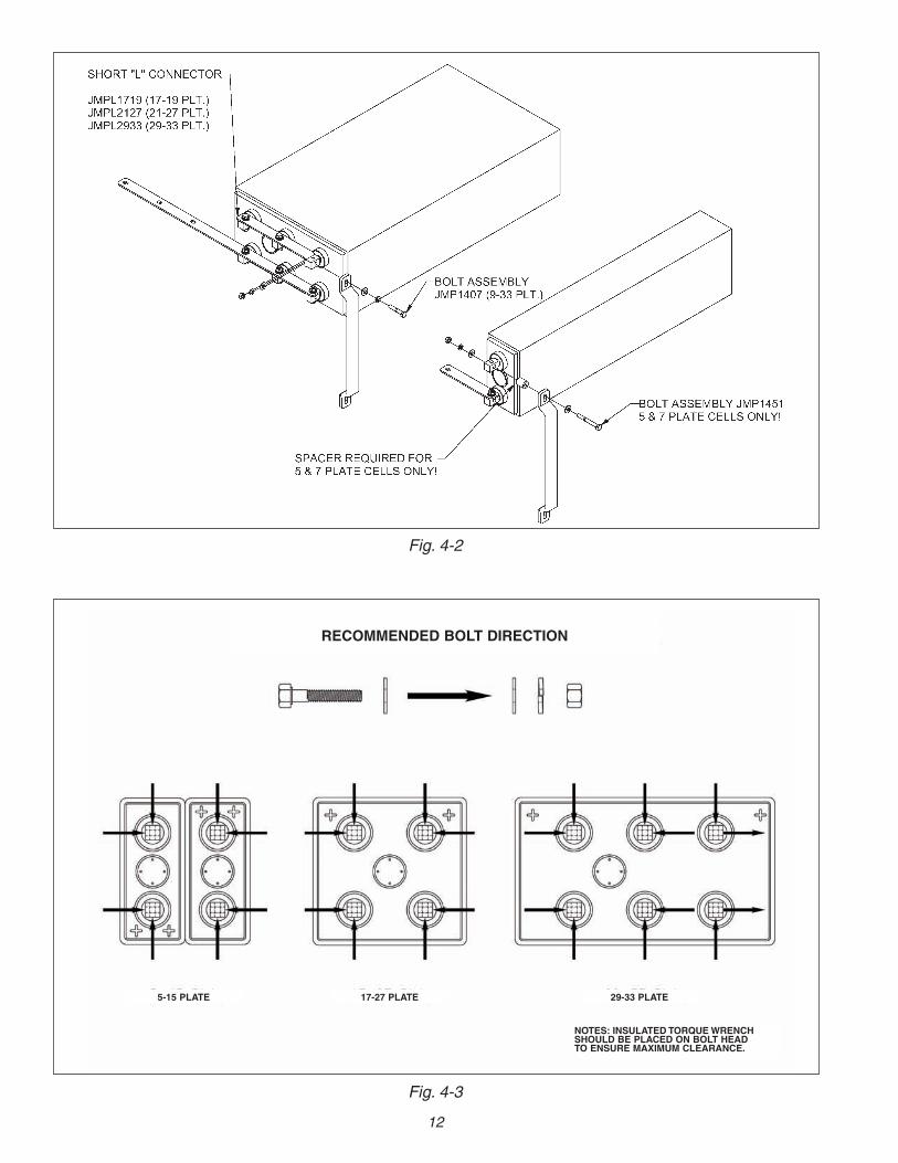
Fig. 4-3
RECOMMENDED BOLT DIRECTION
5-15 PLATE 17-27 PLATE 29-33 PLATE
NOTES: INSULATED TORQUEWRENCHSHOULD BE PLACED ON BOLT HEADTO ENSURE MAXIMUM CLEARANCE.
12
Fig. 4-2
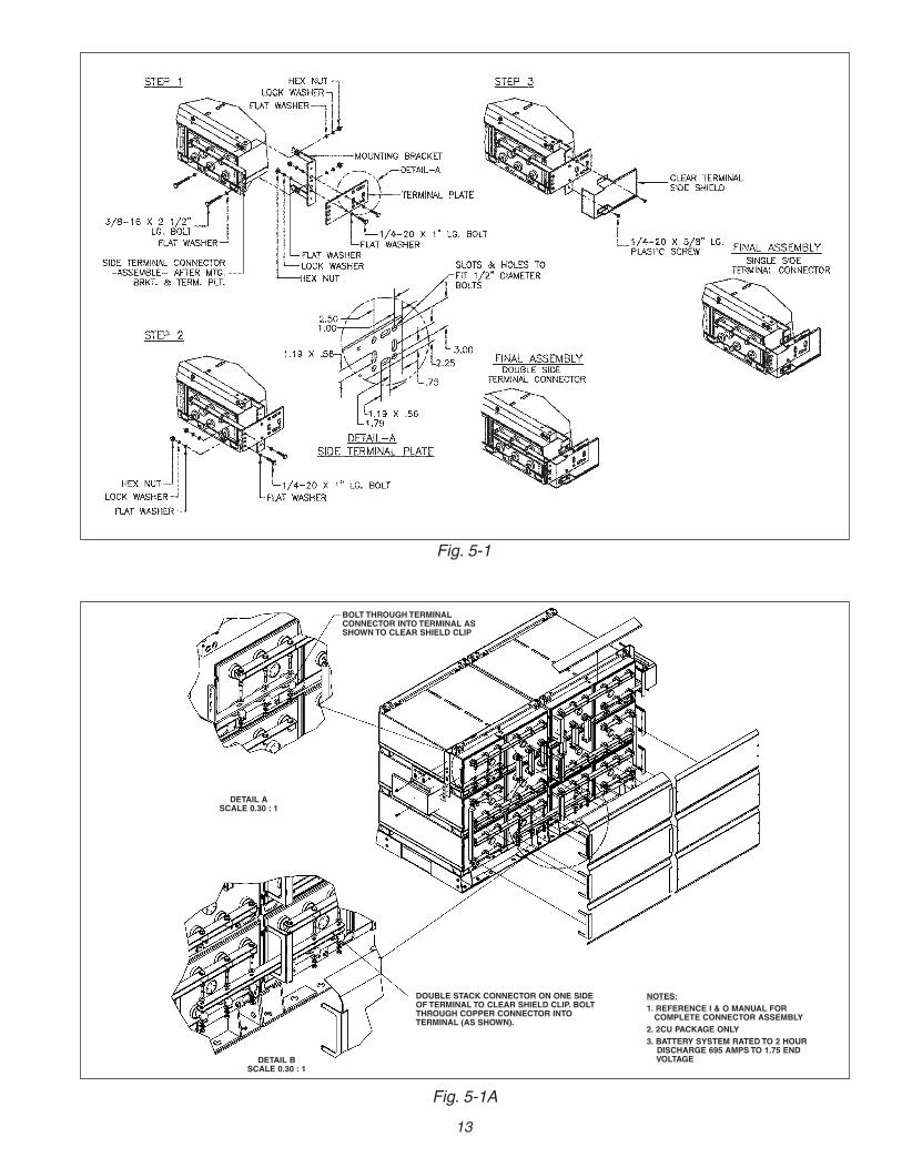
Fig. 5-1
Fig. 5-1A
BOLT THROUGH TERMINALCONNECTOR INTO TERMINAL ASSHOWNTO CLEAR SHIELD CLIP
DETAIL ASCALE 0.30 : 1
DETAIL BSCALE 0.30 : 1
DOUBLE STACK CONNECTOR ON ONE SIDEOF TERMINAL TO CLEAR SHIELD CLIP. BOLTTHROUGH COPPER CONNECTOR INTOTERMINAL (AS SHOWN).
NOTES:1. REFERENCE I & O MANUAL FORCOMPLETE CONNECTOR ASSEMBLY
2. 2CU PACKAGE ONLY3. BATTERY SYSTEM RATED TO 2 HOURDISCHARGE 695 AMPS TO 1.75 ENDVOLTAGE
13
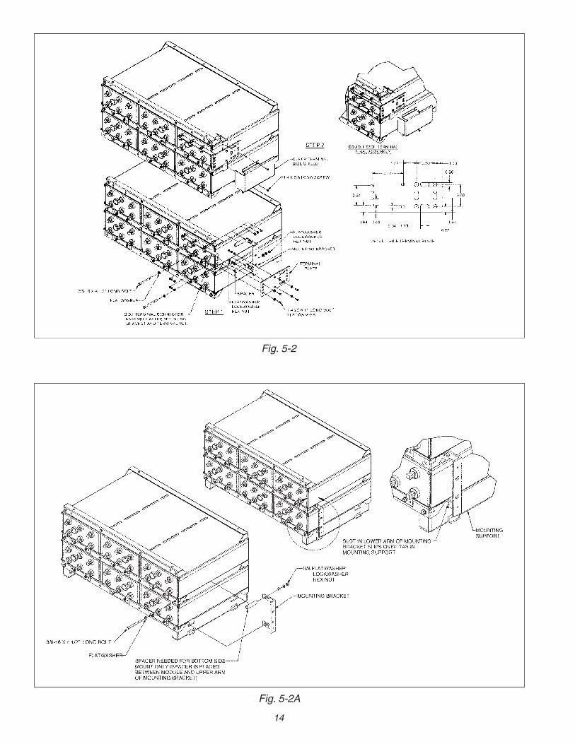
Fig. 5-2A
14
Fig. 5-2
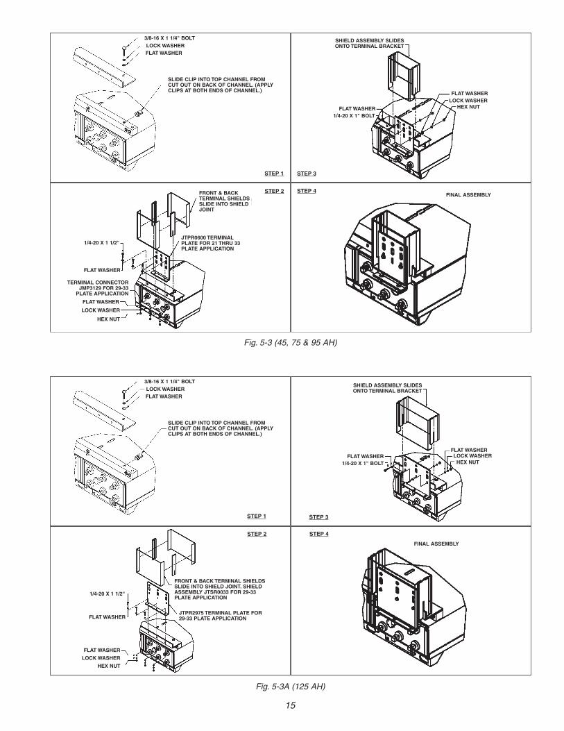
3/8-16 X 1 1/4" BOLTLOCKWASHERFLATWASHER
SLIDE CLIP INTO TOP CHANNEL FROMCUT OUT ON BACK OF CHANNEL. (APPLYCLIPS AT BOTH ENDS OF CHANNEL.)
FRONT & BACKTERMINAL SHIELDSSLIDE INTO SHIELDJOINT
1/4-20 X 1 1/2"
FLATWASHER
FLATWASHER
LOCKWASHER
HEX NUT
STEP 1 STEP 3
STEP 2 STEP 4
FLATWASHERLOCKWASHER
HEX NUT
SHIELD ASSEMBLY SLIDESONTO TERMINAL BRACKET
FLATWASHER1/4-20 X 1" BOLT
FINAL ASSEMBLY
Fig. 5-3A (125 AH)
3/8-16 X 1 1/4" BOLTLOCKWASHERFLATWASHER
SLIDE CLIP INTO TOP CHANNEL FROMCUT OUT ON BACK OF CHANNEL. (APPLYCLIPS AT BOTH ENDS OF CHANNEL.)
FRONT & BACK TERMINAL SHIELDSSLIDE INTO SHIELD JOINT. SHIELDASSEMBLY JTSR0033 FOR 29-33PLATE APPLICATION
1/4-20 X 1 1/2"
FLATWASHER
FLATWASHER
LOCKWASHER
HEX NUT
STEP 1 STEP 3
STEP 2 STEP 4
FLATWASHERLOCKWASHERHEX NUT
SHIELD ASSEMBLY SLIDESONTO TERMINAL BRACKET
FLATWASHER1/4-20 X 1" BOLT
FINAL ASSEMBLY
TERMINAL CONNECTORJMP3129 FOR 29-33PLATE APPLICATION
Fig. 5-3 (45, 75 & 95 AH)
JTPR0600 TERMINALPLATE FOR 21 THRU 33PLATE APPLICATION
JTPR2975 TERMINAL PLATE FOR29-33 PLATE APPLICATION
15
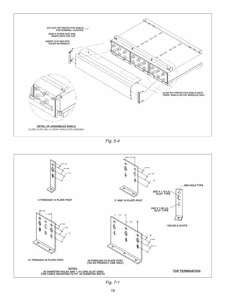
5 THROUGH 15 PLATE POST 17 AND 19 PLATE POST
21 THROUGH 33 PLATE POST
HOLES & SLOTS
29 THROUGH 33 PLATE POST(125 AH PRODUCT LINE ONLY)
NOTES:.56 DIAMETER HOLES AND 1.19 LONG SLOT USEDFOR CABLE MOUNTING TO FIT .50 DIAMETER BOLTD
.56Ø HOLE TYPE
.34Ø X 1.00 LG.SLOT TYPE
.56Ø X 1.19 LG.SLOT TYPE
16
TOP TERMINATION
Fig. 5-4
CUT OUT TOP PROTECTIVE SHIELDFOR TERMINAL LOCATION
SHIELD SLIDES INTO ANDSNAPS ONTO THE CLIP
INSERT CLIP END INTOHOLES ON MODULE
SLIDE TOP PROTECTIVE SHIELD ONTOFRONT SHIELD ON TOP MODULES ONLY
DETAIL OF ASSEMBLED SHIELD(2) END CLIPS AND (1) FRONT SHIELD PER ASSEMBLY
Fig. 7-1
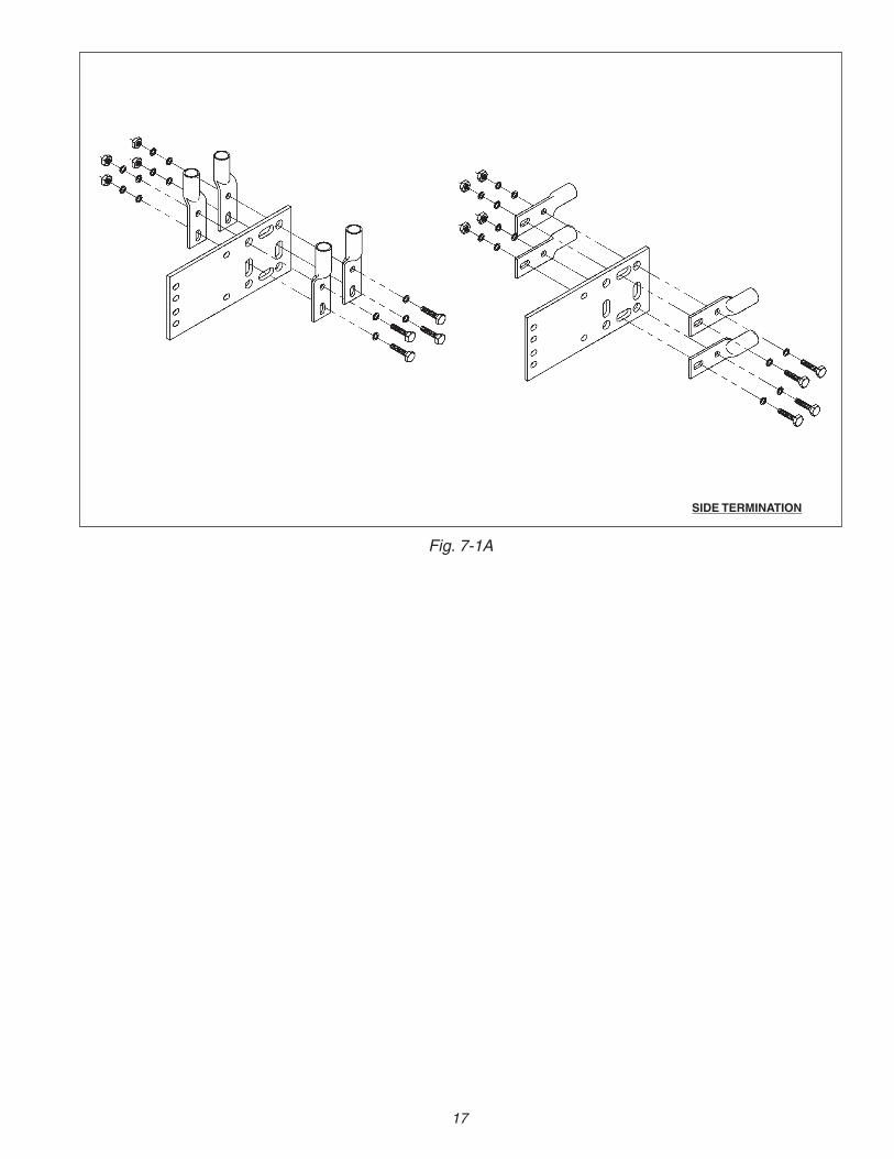
Fig. 7-1A
SIDE TERMINATION
17
18
APPENDIX A
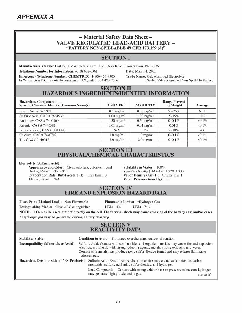
– Material Safety Data Sheet –VALVE REGULATED LEAD-ACID BATTERY –
“BATTERY NON-SPILLABLE 49 CFR 173.159 (d)”
SECTION IIHAZARDOUS INGREDIENTS/IDENTITY INFORMATION
Manufacturer’s Name: East Penn Manufacturing Co., Inc., Deka Road, Lyon Station, PA 19536
Telephone Number for Information: (610) 682-6361 Date: March 4, 2005
Emergency Telephone Number: CHEMTREC: 1-800-424-9300 Trade Name: Gel; Absorbed Electrolyte,In Washington D.C. or outside continental U.S., call 1-202-483-7616 Trade Name: Sealed Valve Regulated Non-Spillable Battery
SECTION IIIPHYSICAL/CHEMICAL CHARACTERISTICS
SECTION IVFIRE AND EXPLOSION HAZARD DATA
Hazardous Components Range PercentSpecific Chemical Identity [Common Name(s)] OSHA PEL ACGIH TLV by Weight Average
Lead, CAS # 7439921 0.05mg/m3 0.05 mg/m3 60–75% 67%Sulfuric Acid, CAS # 7664939 1.00 mg/m3 1.00 mg/m3 5–15% 10%Antimony, CAS # 7440360 0.50 mg/m3 0.50 mg/m3 0–0.1% <0.1%Arsenic, CAS # 7440382 0.01 mg/m3 0.01 mg/m3 0.01% <0.1%Polypropylene, CAS # 9003070 N/A N/A 2–10% 4%Calcium, CAS # 7440702 1.0 mg/m3 1.0 mg/m3 0–0.1% <0.1%Tin, CAS # 7440315 2.0 mg/m3 2.0 mg/m3 0–0.1% <0.1%
Flash Point (Method Used): Non-Flammable Flammable Limits: *Hydrogen Gas
Extinguishing Media: Class ABC extinguisher LEL: 4% UEL: 74%
NOTE: CO2 may be used, but not directly on the cell. The thermal shock may cause cracking of the battery case and/or cases.
* Hydrogen gas may be generated during battery charging.
Electrolyte (Sulfuric Acid):Appearance and Odor: Clear, odorless, colorless liquidBoiling Point: 235–240°FEvaporation Rate (Butyl Acetate=1): Less than 1.0Melting Point: N/A
SECTION I
SECTION VREACTIVITY DATA
Stability: Stable Condition to Avoid: Prolonged overcharging, sources of ignition
Incompatibility (Materials to Avoid): Sulfuric Acid: Contact with combustibles and organic materials may cause fire and explosion.Also reacts violently with strong reducing agents, metals, strong oxidizers and water.Contact with metals may produce toxic sulfur dioxide fumes and may release flammablehydrogen gas.
Hazardous Decomposition of By-Products: Sulfuric Acid: Excessive overcharging or fire may create sulfur trioxide, carbonmonoxide, sulfuric acid mist, sulfur dioxide, and hydrogen.
Lead Compounds: Contact with strong acid or base or presence of nascent hydrogenmay generate highly toxic arsine gas. continued
Solubility in Water: 100%Specific Gravity (H2O=1): 1.270–1.330Vapor Density (Air=1): Greater than 1Vapor Pressure (mm Hg): 10
SECTION VIHEALTH HAZARD DATA
SECTION VIIPRECAUTIONS FOR SAFE HANDLING AND USE
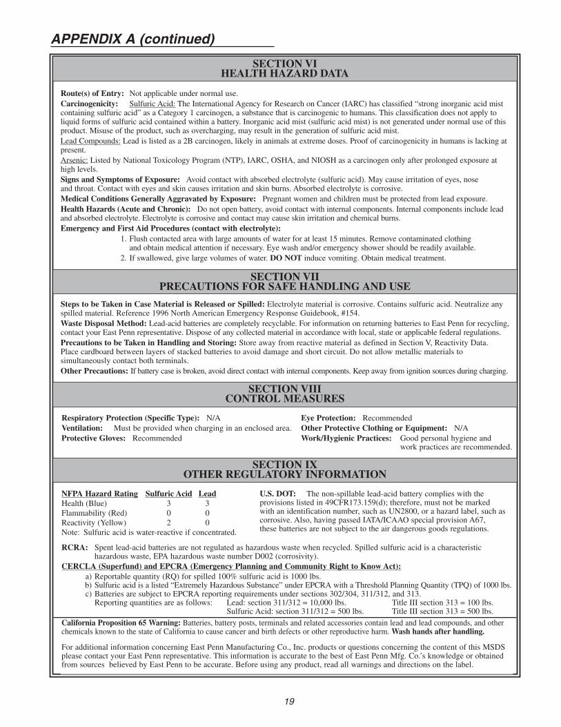
Route(s) of Entry: Not applicable under normal use.Carcinogenicity: Sulfuric Acid: The International Agency for Research on Cancer (IARC) has classified “strong inorganic acid mistcontaining sulfuric acid” as a Category 1 carcinogen, a substance that is carcinogenic to humans. This classification does not apply toliquid forms of sulfuric acid contained within a battery. Inorganic acid mist (sulfuric acid mist) is not generated under normal use of thisproduct. Misuse of the product, such as overcharging, may result in the generation of sulfuric acid mist.Lead Compounds: Lead is listed as a 2B carcinogen, likely in animals at extreme doses. Proof of carcinogenicity in humans is lacking atpresent.Arsenic: Listed by National Toxicology Program (NTP), IARC, OSHA, and NIOSH as a carcinogen only after prolonged exposure athigh levels.Signs and Symptoms of Exposure: Avoid contact with absorbed electrolyte (sulfuric acid). May cause irritation of eyes, noseand throat. Contact with eyes and skin causes irritation and skin burns. Absorbed electrolyte is corrosive.Medical Conditions Generally Aggravated by Exposure: Pregnant women and children must be protected from lead exposure.Health Hazards (Acute and Chronic): Do not open battery, avoid contact with internal components. Internal components include leadand absorbed electrolyte. Electrolyte is corrosive and contact may cause skin irritation and chemical burns.Emergency and First Aid Procedures (contact with electrolyte):
1. Flush contacted area with large amounts of water for at least 15 minutes. Remove contaminated clothingand obtain medical attention if necessary. Eye wash and/or emergency shower should be readily available.
2. If swallowed, give large volumes of water. DO NOT induce vomiting. Obtain medical treatment.
SECTION VIIICONTROL MEASURES
NFPA Hazard Rating Sulfuric Acid LeadHealth (Blue) 3 3Flammability (Red) 0 0Reactivity (Yellow) 2 0Note: Sulfuric acid is water-reactive if concentrated.
SECTION IXOTHER REGULATORY INFORMATION
RCRA: Spent lead-acid batteries are not regulated as hazardous waste when recycled. Spilled sulfuric acid is a characteristichazardous waste, EPA hazardous waste number D002 (corrosivity).
CERCLA (Superfund) and EPCRA (Emergency Planning and Community Right to Know Act):a) Reportable quantity (RQ) for spilled 100% sulfuric acid is 1000 lbs.b) Sulfuric acid is a listed “Extremely Hazardous Substance” under EPCRA with a Threshold Planning Quantity (TPQ) of 1000 lbs.c) Batteries are subject to EPCRA reporting requirements under sections 302/304, 311/312, and 313.Reporting quantities are as follows: Lead: section 311/312 = 10,000 lbs. Title III section 313 = 100 lbs.
Sulfuric Acid: section 311/312 = 500 lbs. Title III section 313 = 500 lbs.California Proposition 65 Warning: Batteries, battery posts, terminals and related accessories contain lead and lead compounds, and otherchemicals known to the state of California to cause cancer and birth defects or other reproductive harm.Wash hands after handling.
For additional information concerning East Penn Manufacturing Co., Inc. products or questions concerning the content of this MSDSplease contact your East Penn representative. This information is accurate to the best of East Penn Mfg. Co.’s knowledge or obtainedfrom sources believed by East Penn to be accurate. Before using any product, read all warnings and directions on the label.
Respiratory Protection (Specific Type): N/AVentilation: Must be provided when charging in an enclosed area.Protective Gloves: Recommended
Eye Protection: RecommendedOther Protective Clothing or Equipment: N/AWork/Hygienic Practices: Good personal hygiene and
work practices are recommended.
APPENDIX A (continued)
U.S. DOT: The non-spillable lead-acid battery complies with theprovisions listed in 49CFR173.159(d); therefore, must not be markedwith an identification number, such as UN2800, or a hazard label, such ascorrosive. Also, having passed IATA/ICAAO special provision A67,these batteries are not subject to the air dangerous goods regulations.
Steps to be Taken in Case Material is Released or Spilled: Electrolyte material is corrosive. Contains sulfuric acid. Neutralize anyspilled material. Reference 1996 North American Emergency Response Guidebook, #154.Waste Disposal Method: Lead-acid batteries are completely recyclable. For information on returning batteries to East Penn for recycling,contact your East Penn representative. Dispose of any collected material in accordance with local, state or applicable federal regulations.Precautions to be Taken in Handling and Storing: Store away from reactive material as defined in Section V, Reactivity Data.Place cardboard between layers of stacked batteries to avoid damage and short circuit. Do not allow metallic materials tosimultaneously contact both terminals.Other Precautions: If battery case is broken, avoid direct contact with internal components. Keep away from ignition sources during charging.
19
APPENDIX B
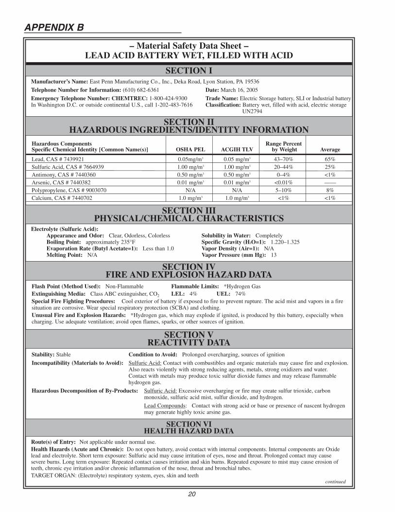
– Material Safety Data Sheet –LEAD ACID BATTERYWET, FILLEDWITH ACID
SECTION IIHAZARDOUS INGREDIENTS/IDENTITY INFORMATION
Manufacturer’s Name: East Penn Manufacturing Co., Inc., Deka Road, Lyon Station, PA 19536
Telephone Number for Information: (610) 682-6361 Date: March 16, 2005
Emergency Telephone Number: CHEMTREC: 1-800-424-9300 Trade Name: Electric Storage battery, SLI or Industrial batteryIn Washington D.C. or outside continental U.S., call 1-202-483-7616 Classification: Battery wet, filled with acid, electric storage
UN2794
SECTION IIIPHYSICAL/CHEMICAL CHARACTERISTICS
SECTION IVFIRE AND EXPLOSION HAZARD DATA
Hazardous Components Range PercentSpecific Chemical Identity [Common Name(s)] OSHA PEL ACGIH TLV by Weight Average
Lead, CAS # 7439921 0.05mg/m3 0.05 mg/m3 43–70% 65%Sulfuric Acid, CAS # 7664939 1.00 mg/m3 1.00 mg/m3 20–44% 25%Antimony, CAS # 7440360 0.50 mg/m3 0.50 mg/m3 0–4% <1%Arsenic, CAS # 7440382 0.01 mg/m3 0.01 mg/m3 <0.01% ——Polypropylene, CAS # 9003070 N/A N/A 5–10% 8%Calcium, CAS # 7440702 1.0 mg/m3 1.0 mg/m3 <1% <1%
Flash Point (Method Used): Non-Flammable Flammable Limits: *Hydrogen GasExtinguishing Media: Class ABC extinguisher, CO2 LEL: 4% UEL: 74%Special Fire Fighting Procedures: Cool exterior of battery if exposed to fire to prevent rupture. The acid mist and vapors in a firesituation are corrosive. Wear special respiratory protection (SCBA) and clothing.Unusual Fire and Explosion Hazards: *Hydrogen gas, which may explode if ignited, is produced by this battery, especially whencharging. Use adequate ventilation; avoid open flames, sparks, or other sources of ignition.
Electrolyte (Sulfuric Acid):Appearance and Odor: Clear, Odorless, ColorlessBoiling Point: approximately 235°FEvaporation Rate (Butyl Acetate=1): Less than 1.0Melting Point: N/A
SECTION I
SECTION VREACTIVITY DATA
Stability: Stable Condition to Avoid: Prolonged overcharging, sources of ignition
Incompatibility (Materials to Avoid): Sulfuric Acid: Contact with combustibles and organic materials may cause fire and explosion.Also reacts violently with strong reducing agents, metals, strong oxidizers and water.Contact with metals may produce toxic sulfur dioxide fumes and may release flammablehydrogen gas.
Hazardous Decomposition of By-Products: Sulfuric Acid: Excessive overcharging or fire may create sulfur trioxide, carbonmonoxide, sulfuric acid mist, sulfur dioxide, and hydrogen.
Lead Compounds: Contact with strong acid or base or presence of nascent hydrogenmay generate highly toxic arsine gas.
Solubility in Water: CompletelySpecific Gravity (H2O=1): 1.220–1.325Vapor Density (Air=1): N/AVapor Pressure (mm Hg): 13
20
SECTION VIHEALTH HAZARD DATA
Route(s) of Entry: Not applicable under normal use.Health Hazards (Acute and Chronic): Do not open battery, avoid contact with internal components. Internal components are Oxidelead and electrolyte. Short term exposure: Sulfuric acid may cause irritation of eyes, nose and throat. Prolonged contact may causesevere burns. Long term exposure: Repeated contact causes irritation and skin burns. Repeated exposure to mist may cause erosion ofteeth, chronic eye irritation and/or chronic inflammation of the nose, throat and bronchial tubes.TARGET ORGAN: (Electrolyte) respiratory system, eyes, skin and teeth
continued
21
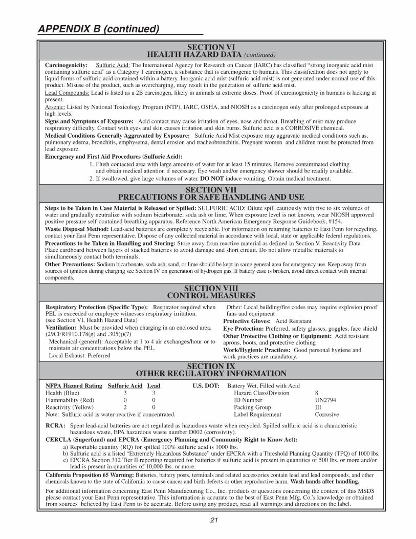
SECTION VIHEALTH HAZARD DATA (continued)
SECTION VIIPRECAUTIONS FOR SAFE HANDLING AND USE
Carcinogenicity: Sulfuric Acid: The International Agency for Research on Cancer (IARC) has classified “strong inorganic acid mistcontaining sulfuric acid” as a Category 1 carcinogen, a substance that is carcinogenic to humans. This classification does not apply toliquid forms of sulfuric acid contained within a battery. Inorganic acid mist (sulfuric acid mist) is not generated under normal use of thisproduct. Misuse of the product, such as overcharging, may result in the generation of sulfuric acid mist.Lead Compounds: Lead is listed as a 2B carcinogen, likely in animals at extreme doses. Proof of carcinogenicity in humans is lacking atpresent.Arsenic: Listed by National Toxicology Program (NTP), IARC, OSHA, and NIOSH as a carcinogen only after prolonged exposure athigh levels.Signs and Symptoms of Exposure: Acid contact may cause irritation of eyes, nose and throat. Breathing of mist may producerespiratory difficulty. Contact with eyes and skin causes irritation and skin burns. Sulfuric acid is a CORROSIVE chemical.Medical Conditions Generally Aggravated by Exposure: Sulfuric Acid Mist exposure may aggravate medical conditions such as,pulmonary edema, bronchitis, emphysema, dental erosion and tracheobronchitis. Pregnant women and children must be protected fromlead exposure.Emergency and First Aid Procedures (Sulfuric Acid):
1. Flush contacted area with large amounts of water for at least 15 minutes. Remove contaminated clothingand obtain medical attention if necessary. Eye wash and/or emergency shower should be readily available.
2. If swallowed, give large volumes of water. DO NOT induce vomiting. Obtain medical treatment.
SECTION VIIICONTROL MEASURES
NFPA Hazard Rating Sulfuric Acid LeadHealth (Blue) 3 3Flammability (Red) 0 0Reactivity (Yellow) 2 0Note: Sulfuric acid is water-reactive if concentrated.
SECTION IXOTHER REGULATORY INFORMATION
RCRA: Spent lead-acid batteries are not regulated as hazardous waste when recycled. Spilled sulfuric acid is a characteristichazardous waste, EPA hazardous waste number D002 (corrosivity).
CERCLA (Superfund) and EPCRA (Emergency Planning and Community Right to Know Act):a) Reportable quantity (RQ) for spilled 100% sulfuric acid is 1000 lbs.b) Sulfuric acid is a listed “Extremely Hazardous Substance” under EPCRA with a Threshold Planning Quantity (TPQ) of 1000 lbs.c) EPCRA Section 312 Tier II reporting required for batteries if sulfuric acid is present in quantities of 500 lbs. or more and/orlead is present in quantities of 10,000 lbs. or more.
California Proposition 65 Warning: Batteries, battery posts, terminals and related accessories contain lead and lead compounds, and otherchemicals known to the state of California to cause cancer and birth defects or other reproductive harm.Wash hands after handling.
For additional information concerning East Penn Manufacturing Co., Inc. products or questions concerning the content of this MSDSplease contact your East Penn representative. This information is accurate to the best of East Penn Mfg. Co.’s knowledge or obtainedfrom sources believed by East Penn to be accurate. Before using any product, read all warnings and directions on the label.
Respiratory Protection (Specific Type): Respirator required whenPEL is exceeded or employee witnesses respiratory irritation.(see Section VI, Health Hazard Data)Ventilation: Must be provided when charging in an enclosed area.(29CFR1910.178(g) and .305(j)(7)Mechanical (general): Acceptable at 1 to 4 air exchanges/hour or tomaintain air concentrations below the PEL.Local Exhaust: Preferred
Other: Local building/fire codes may require explosion prooffans and equipmentProtective Gloves: Acid ResistantEye Protection: Preferred, safety glasses, goggles, face shieldOther Protective Clothing or Equipment: Acid resistantaprons, boots, and protective clothingWork/Hygienic Practices: Good personal hygiene andwork practices are mandatory.
APPENDIX B (continued)
U.S. DOT: Battery Wet, Filled with AcidHazard Class/Division 8ID Number UN2794Packing Group IIILabel Requirement Corrosive
Steps to be Taken in Case Material is Released or Spilled: SULFURIC ACID: Dilute spill cautiously with five to six volumes ofwater and gradually neutralize with sodium bicarbonate, soda ash or lime. When exposure level is not known, wear NIOSH approvedpositive pressure self-contained breathing apparatus. Reference North American Emergency Response Guidebook, #154.Waste Disposal Method: Lead-acid batteries are completely recyclable. For information on returning batteries to East Penn for recycling,contact your East Penn representative. Dispose of any collected material in accordance with local, state or applicable federal regulations.Precautions to be Taken in Handling and Storing: Store away from reactive material as defined in Section V, Reactivity Data.Place cardboard between layers of stacked batteries to avoid damage and short circuit. Do not allow metallic materials tosimultaneously contact both terminals.Other Precautions: Sodium bicarbonate, soda ash, sand, or lime should be kept in same general area for emergency use. Keep away fromsources of ignition during charging see Section IV on generation of hydrogen gas. If battery case is broken, avoid direct contact with internalcomponents.
22
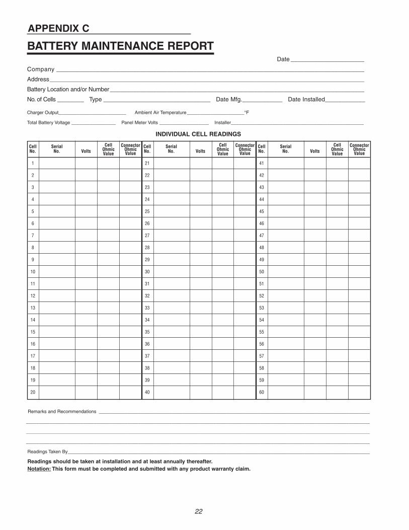
Remarks and Recommendations ________________________________________________________________________________________________________
____________________________________________________________________________________________________________________________________
____________________________________________________________________________________________________________________________________
____________________________________________________________________________________________________________________________________
Readings Taken By____________________________________________________________________________________________________________________
Readings should be taken at installation and at least annually thereafter.Notation: This form must be completed and submitted with any product warranty claim.
Cell SerialNo. No. Volts
1
2
3
4
5
6
7
8
9
10
11
12
13
14
15
16
17
18
19
20
BATTERY MAINTENANCE REPORTDate ______________________
Company ____________________________________________________________________________________________
Address______________________________________________________________________________________________
Battery Location and/or Number____________________________________________________________________________
No. of Cells ________ Type ________________________________ Date Mfg.____________ Date Installed____________
Charger Output__________________________ Ambient Air Temperature______________________°F
Total Battery Voltage _________________ Panel Meter Volts ___________________ Installer___________________________________________________
INDIVIDUAL CELL READINGS
APPENDIX C
Cell SerialNo. No. Volts
21
22
23
24
25
26
27
28
29
30
31
32
33
34
35
36
37
38
39
40
Cell SerialNo. No. Volts
41
42
43
44
45
46
47
48
49
50
51
52
53
54
55
56
57
58
59
60
ConnectorOhmicValue
CellOhmicValue
ConnectorOhmicValue
CellOhmicValue
ConnectorOhmicValue
CellOhmicValue
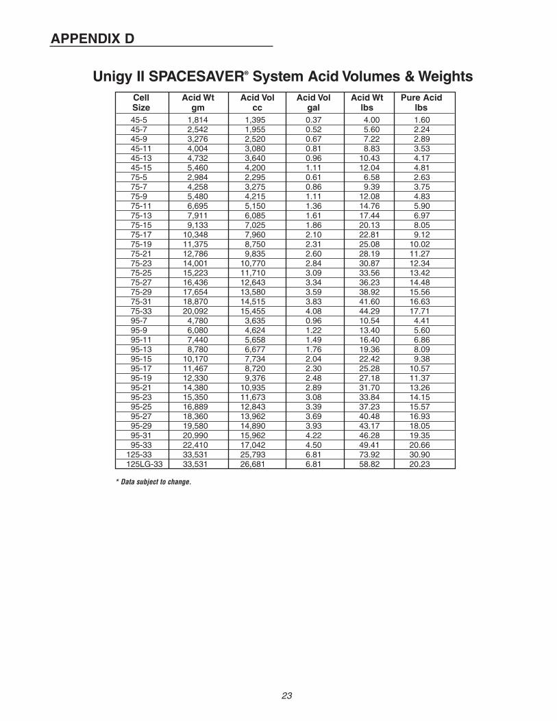
Cell Acid Wt Acid Vol Acid Vol Acid Wt Pure AcidSize gm cc gal lbs lbs45-5 1,814 1,395 0.37 4.00 1.6045-7 2,542 1,955 0.52 5.60 2.2445-9 3,276 2,520 0.67 7.22 2.8945-11 4,004 3,080 0.81 8.83 3.5345-13 4,732 3,640 0.96 10.43 4.1745-15 5,460 4,200 1.11 12.04 4.8175-5 2,984 2,295 0.61 6.58 2.6375-7 4,258 3,275 0.86 9.39 3.7575-9 5,480 4,215 1.11 12.08 4.8375-11 6,695 5,150 1.36 14.76 5.9075-13 7,911 6,085 1.61 17.44 6.9775-15 9,133 7,025 1.86 20.13 8.0575-17 10,348 7,960 2.10 22.81 9.1275-19 11,375 8,750 2.31 25.08 10.0275-21 12,786 9,835 2.60 28.19 11.2775-23 14,001 10,770 2.84 30.87 12.3475-25 15,223 11,710 3.09 33.56 13.4275-27 16,436 12,643 3.34 36.23 14.4875-29 17,654 13,580 3.59 38.92 15.5675-31 18,870 14,515 3.83 41.60 16.6375-33 20,092 15,455 4.08 44.29 17.7195-7 4,780 3,635 0.96 10.54 4.4195-9 6,080 4,624 1.22 13.40 5.6095-11 7,440 5,658 1.49 16.40 6.8695-13 8,780 6,677 1.76 19.36 8.0995-15 10,170 7,734 2.04 22.42 9.3895-17 11,467 8,720 2.30 25.28 10.5795-19 12,330 9,376 2.48 27.18 11.3795-21 14,380 10,935 2.89 31.70 13.2695-23 15,350 11,673 3.08 33.84 14.1595-25 16,889 12,843 3.39 37.23 15.5795-27 18,360 13,962 3.69 40.48 16.9395-29 19,580 14,890 3.93 43.17 18.0595-31 20,990 15,962 4.22 46.28 19.3595-33 22,410 17,042 4.50 49.41 20.66125-33 33,531 25,793 6.81 73.92 30.90125LG-33 33,531 26,681 6.81 58.82 20.23
Unigy II SPACESAVER® System Acid Volumes &Weights
* Data subject to change.
APPENDIX D
23

Lyon Station, PA 19536-0147 • Phone: 610-682-6361 • Fax: 610-682-4781Order Department Hotline: 610-682-4231www.eastpennunigy.com • E-mail: [email protected]. Form No. 1112 Rev. 11/07© 2007 by EPM Printed in U.S.A.
All data subject to change without notice.No part of this document may be copied or reproduced, electronically
or mechanically, without written permission from the company.
DISTRIBUTED BY:“POWERED FOR PERFORMANCE ” ®