Embed Size (px)
Citation preview

Space Telecommunications Radio System (STRS) Architecture StandardRelease 1.02.1
NASA/TM—2010-216809/REV1
March 2012
This printing replaces NASA/TM—2010-216809, December 2010.
https://ntrs.nasa.gov/search.jsp?R=20110002806 2020-04-20T05:29:15+00:00Z

NASA STI Program . . . in Profi le
Since its founding, NASA has been dedicated to the advancement of aeronautics and space science. The NASA Scientifi c and Technical Information (STI) program plays a key part in helping NASA maintain this important role.
The NASA STI Program operates under the auspices of the Agency Chief Information Offi cer. It collects, organizes, provides for archiving, and disseminates NASA’s STI. The NASA STI program provides access to the NASA Aeronautics and Space Database and its public interface, the NASA Technical Reports Server, thus providing one of the largest collections of aeronautical and space science STI in the world. Results are published in both non-NASA channels and by NASA in the NASA STI Report Series, which includes the following report types: • TECHNICAL PUBLICATION. Reports of
completed research or a major signifi cant phase of research that present the results of NASA programs and include extensive data or theoretical analysis. Includes compilations of signifi cant scientifi c and technical data and information deemed to be of continuing reference value. NASA counterpart of peer-reviewed formal professional papers but has less stringent limitations on manuscript length and extent of graphic presentations.
• TECHNICAL MEMORANDUM. Scientifi c
and technical fi ndings that are preliminary or of specialized interest, e.g., quick release reports, working papers, and bibliographies that contain minimal annotation. Does not contain extensive analysis.
• CONTRACTOR REPORT. Scientifi c and
technical fi ndings by NASA-sponsored contractors and grantees.
• CONFERENCE PUBLICATION. Collected papers from scientifi c and technical conferences, symposia, seminars, or other meetings sponsored or cosponsored by NASA.
• SPECIAL PUBLICATION. Scientifi c,
technical, or historical information from NASA programs, projects, and missions, often concerned with subjects having substantial public interest.
• TECHNICAL TRANSLATION. English-
language translations of foreign scientifi c and technical material pertinent to NASA’s mission.
Specialized services also include creating custom thesauri, building customized databases, organizing and publishing research results.
For more information about the NASA STI program, see the following:
• Access the NASA STI program home page at http://www.sti.nasa.gov
• E-mail your question via the Internet to help@
sti.nasa.gov • Fax your question to the NASA STI Help Desk
at 443–757–5803 • Telephone the NASA STI Help Desk at 443–757–5802 • Write to:
NASA Center for AeroSpace Information (CASI) 7115 Standard Drive Hanover, MD 21076–1320

Space Telecommunications Radio System (STRS) Architecture StandardRelease 1.02.1
NASA/TM—2010-216809/REV1
March 2012
National Aeronautics andSpace Administration
Glenn Research CenterCleveland, Ohio 44135
This printing replaces NASA/TM—2010-216809, December 2010.

Available from
NASA Center for Aerospace Information7115 Standard DriveHanover, MD 21076–1320
National Technical Information Service5301 Shawnee Road
Alexandria, VA 22312
Available electronically at http://www.sti.nasa.gov
Trade names and trademarks are used in this report for identifi cation only. Their usage does not constitute an offi cial endorsement, either expressed or implied, by the National Aeronautics and
Space Administration.
Level of Review: This material has been technically reviewed by technical management.
Document Change History
NASA/TM—2010-216809/REV1, December 2010
Space Telecommunications Radio System (STRS) Architecture Standard, Release 1.02.1Richard C. Reinhart
This printing replaces NASA/TM—2010-216809, December 2010.It contains the following changes:
Since participation occurred from different authors, reviewers, and contributors, the author names and their affi liations were removed from the front cover and listed in the Acknowledgments.
Principal AuthorsRichard C. Reinhart, Thomas J. Kacpura, Louis M. Handler, Sandra K. Johnson, Janette C. Briones, Jennifer M. Nappier, and Joseph A. DowneyGlenn Research Center, Cleveland, Ohio
C. Steve HallAnalex Corporation, Cleveland, Ohio
Dale J. MortensenASRC Aerospace Corporation, Cleveland, Ohio
James P. Lux Jet Propulsion Laboratory, Pasadena, California
Key Industry ParticipantsCarl Smith and John LiebetreuGeneral Dynamics Corporation, C4 Systems
Vince KovarikHarris Corporation
Acknowledgments
Key Industry Participants (continued)Mark Scoville L-3 Communications, Salt Lake City, Utah
Jerry BicklePrism Tech, Woburn, Massachusetts
Reviewers and ContributorsDavid J. IsraelGoddard Space Flight Center, Greenbelt, Maryland
Andrew L. BenjaminJohnson Space Center, Houston, Texas
Allen Farrington, Yong Chong, and Ken PetersJet Propulsion Laboratory, Pasadena, California
SDR Forum Review, Contributing Member CompaniesGeneral Dynamics HarrisPrism Tech L-3 CommunicationsBoeing Lockheed MartinCincinnati Electronics
There is a variety of inputs contributing to the STRS Architecture over a period of several years. Participation occurred from different authors, reviewers, and contributors to the overall Architecture Defi nition.

NASA/TM—2010-216809/REV1 iii
Preface This document describes an architecture standard for NASA space communication radio transceivers.
This architecture is a required but evolving standard for communication transceiver developments among NASA space missions. Although the architecture was defined to support space-based platforms, the architecture may also be applied to ground station radios.
The STRS Architecture strives to provide commonality among NASA radio developments to take full advantage of emerging software defined radio technologies from mission to mission. This architecture serves as an overall framework for the design, development, operation, and upgrade of these software based radios.
This document is under the configuration management of the NASA Glenn Research Center (GRC) at Lewis Field. Change requests and comments to this document shall be submitted to the contact below along with supportive material justifying the proposed change.
Questions and proposed changes concerning this document shall be addressed to: STRS Architecture Manager Communications Division Glenn Research Center Mail Stop 54–8 Cleveland, Ohio 44135 or email contact to: [email protected]


NASA/TM—2010-216809/REV1 v
Contents Preface ......................................................................................................................................................... iii Executive Summary ..................................................................................................................................... ix 1.0 Introduction .......................................................................................................................................... 1
1.1 Terminology ................................................................................................................................ 2 2.0 Scope .................................................................................................................................................... 3 3.0 Documents ............................................................................................................................................ 4
3.1 Applicable Documents ................................................................................................................ 4 3.2 Reference Documents ................................................................................................................. 4 3.3 Background Documents .............................................................................................................. 4
4.0 Hardware Architecture ......................................................................................................................... 5 4.1 Generalized Hardware Architecture and Specification ............................................................... 5
4.1.1 Components .................................................................................................................. 7 4.1.2 Functions ....................................................................................................................... 8 4.1.3 Interfaces ....................................................................................................................... 8
4.2 Module Type Specification ....................................................................................................... 10 4.2.1 General-Purpose Processing Module (GPM) .............................................................. 10 4.2.2 Signal Processing Module (SPM) ............................................................................... 12 4.2.3 Radio Frequency Module (RFM) ................................................................................ 15 4.2.4 Security Module (SEC) ............................................................................................... 17 4.2.5 Networking Module .................................................................................................... 17 4.2.6 Optical Module (OM) ................................................................................................. 17
4.3 Hardware Interface Description ................................................................................................ 17 4.3.1 Control and Data Interface .......................................................................................... 18 4.3.2 DC Power Interface ..................................................................................................... 19 4.3.3 Thermal and Mechanical Interface .............................................................................. 19
5.0 Applications ....................................................................................................................................... 20 5.1 Application Implementation ..................................................................................................... 20 5.2 Application Selection ................................................................................................................ 20 5.3 Navigation Services .................................................................................................................. 21 5.4 Application Repository Submissions ........................................................................................ 21
6.0 Firmware Architecture ....................................................................................................................... 21 6.1 Specialized Hardware Interfaces ............................................................................................... 22 6.2 Proposed Firmware Architecture Extension ............................................................................. 24
7.0 Software Architecture ......................................................................................................................... 25 7.1 Software Layer Interfaces ......................................................................................................... 25 7.2 Infrastructure ............................................................................................................................. 30 7.3 STRS APIs ................................................................................................................................ 31
7.3.1 STRS Application-provided Application Control API ............................................... 31 7.3.2 STRS Infrastructure-Provided Application Control API ............................................ 40 7.3.3 STRS Infrastructure Application Setup API ............................................................... 45 7.3.4 STRS Infrastructure Data Sink .................................................................................... 48 7.3.5 STRS Infrastructure Data Source ................................................................................ 48 7.3.6 STRS Infrastructure Device Control API.................................................................... 49 7.3.7 STRS Infrastructure File Control API ......................................................................... 52 7.3.8 STRS Infrastructure Messaging API ........................................................................... 55 7.3.9 STRS Infrastructure Time Control API ...................................................................... 57 7.3.10 STRS Predefined Data ................................................................................................ 61
7.4 Portable Operating System Interface (POSIX) ......................................................................... 62 7.4.1 STRS Application Environment Profile ...................................................................... 63

NASA/TM—2010-216809/REV1 vi
7.5 Network Stack ........................................................................................................................... 65 7.6 Operating System ...................................................................................................................... 65 7.7 Hardware Abstraction Layer ..................................................................................................... 66
8.0 External Command and Telemetry Interface ..................................................................................... 67 9.0 Configuration File(s) .......................................................................................................................... 70
9.1 General Configuration File Format Definition and Use ........................................................... 70 9.2 Platform Configuration Files .................................................................................................... 72 9.3 Application Configuration Files ................................................................................................ 73
Appendix A .—Example Configuration Files ............................................................................................. 75 A.1 STRS Platform Configuration File Hardware Example ............................................................ 75 A.2 STRS Platform Configuration File Software Example ............................................................. 76 A.3 STRS Application Configuration Files Example ...................................................................... 80
Appendix B .—POSIX API Profile ............................................................................................................ 83 Appendix C .—Document History Log ...................................................................................................... 87
List of Tables
Table 4.1.—STRS Module Interface Characterization ............................................................................... 18 Table 4.2.—Example—DC Power Interface (Platform Supplied) .............................................................. 19 Table 7.1.—STRS Architecture Subsystem Key ........................................................................................ 27 Table 7.2.—STRS Software Component Descriptions ............................................................................... 29 Table 7.3.—APP_Configure() .................................................................................................................... 35 Table 7.4.—APP_GroundTest() ................................................................................................................. 36 Table 7.5.—APP_Initialize() ...................................................................................................................... 36 Table 7.6.—APP_Instance() ....................................................................................................................... 37 Table 7.7.—APP_Query() .......................................................................................................................... 37 Table 7.8.—APP_Read() ............................................................................................................................ 38 Table 7.9.—APP_ReleaseObject() ............................................................................................................. 38 Table 7.10.—APP_RunTest() ..................................................................................................................... 39 Table 7.11.—APP_Start() ........................................................................................................................... 39 Table 7.12.—APP_Stop() ........................................................................................................................... 40 Table 7.13.—APP_Write() ......................................................................................................................... 40 Table 7.14.—STRS_Configure() ................................................................................................................ 41 Table 7.15.—STRS_GroundTest() ............................................................................................................. 42 Table 7.16.—STRS_Initialize() .................................................................................................................. 42 Table 7.17.—STRS_Query() ...................................................................................................................... 43 Table 7.18.—STRS_ReleaseObject() ......................................................................................................... 43 Table 7.19.—STRS_Runtest() .................................................................................................................... 44 Table 7.20.—STRS_Start() ......................................................................................................................... 44 Table 7.21.—STRS_Stop() ......................................................................................................................... 44 Table 7.22.—STRS_AbortApp() ................................................................................................................ 45 Table 7.23.—STRS_GetErrorQueue() ........................................................................................................ 46 Table 7.24.—STRS_HandleRequest() ........................................................................................................ 46 Table 7.25.—STRS_InstantiateApp() ......................................................................................................... 47 Table 7.26.—STRS_IsOK() ........................................................................................................................ 47 Table 7.27.—STRS_Log() .......................................................................................................................... 47 Table 7.28.—STRS_Write() ....................................................................................................................... 48 Table 7.29.—STRS_Read() ........................................................................................................................ 48 Table 7.30.—STRS_DeviceClose() ............................................................................................................ 49 Table 7.31.—STRS_DeviceFlush() ............................................................................................................ 50
NASA/TM—2010-216809/REV1 vii
Table 7.32.—STRS_DeviceLoad() ............................................................................................................. 50 Table 7.33.—STRS_DeviceOpen() ............................................................................................................ 50 Table 7.34.—STRS_DeviceReset() ............................................................................................................ 51 Table 7.35.—STRS_DeviceStart() ............................................................................................................. 51 Table 7.36.—STRS_DeviceStop() .............................................................................................................. 51 Table 7.37.—STRS_DeviceUnload() ......................................................................................................... 52 Table 7.38.—STRS_SetISR() ..................................................................................................................... 52 Table 7.39.—STRS_FileClose() ................................................................................................................. 53 Table 7.40.—STRS_FileGetFreeSpace() .................................................................................................... 53 Table 7.41.—STRS_FileGetSize() ............................................................................................................. 53 Table 7.42.—STRS_FileGetStreamPointer() ............................................................................................. 54 Table 7.43.—STRS_FileOpen() ................................................................................................................. 54 Table 7.44.—STRS_FileRemove() ............................................................................................................. 55 Table 7.45.—STRS_FileRename() ............................................................................................................. 55 Table 7.46.—STRS_QueueCreate() ........................................................................................................... 56 Table 7.47.—STRS_QueueDelete() ........................................................................................................... 56 Table 7.48.—STRS_Register() ................................................................................................................... 57 Table 7.49.—STRS_Unregister() ............................................................................................................... 57 Table 7.50.—STRS_GetNanoseconds() ..................................................................................................... 58 Table 7.51.—STRS_GetSeconds() ............................................................................................................. 58 Table 7.52.—STRS_GetTime() .................................................................................................................. 59 Table 7.53.—STRS_GetTimeWarp() ......................................................................................................... 59 Table 7.54.—STRS_SetTime() ................................................................................................................... 60 Table 7.55.—STRS_Synch() ...................................................................................................................... 60 Table 7.56.—STRS Predefined Data .......................................................................................................... 61 Table 7.57.—Replacements for Unsafe Functions ..................................................................................... 65 Table 7.58.—Sample HAL Documentation ................................................................................................ 67 Table 8.1.—Suggested services implemented by the STRS Command and Telemetry Interface .............. 69
List of Figures
Figure 4.1.—Hardware Architecture Diagram Key. ..................................................................................... 6 Figure 4.2.—STRS Hardware Architecture Implementation ........................................................................ 7 Figure 4.3.—GPM Architecture Details. .................................................................................................... 11 Figure 4.4.—SPM Architecture Details. ..................................................................................................... 13 Figure 4.5.—RFM Architecture Details. .................................................................................................... 16 Figure 5.1.—Waveform Component Instantiation...................................................................................... 20 Figure 6.1.—High-level Software and Firmware Waveform Applications Interfaces. .............................. 23 Figure 6.2.—Proposed Firmware Architecture Extension .......................................................................... 24 Figure 7.1.—STRS Software Execution Model. ......................................................................................... 26 Figure 7.2.—STRS Layered Structure in UML. ......................................................................................... 26 Figure 7.3.—STRS Operating Environment. .............................................................................................. 28 Figure 7.4.—POSIX Compliant versus Conformant. ................................................................................. 30 Figure 7.5.—STRS infrastructure. .............................................................................................................. 30 Figure 7.6.—STRS Application/Device Structure. ..................................................................................... 32 Figure 7.7.—STRS Application State Diagram. ......................................................................................... 34 Figure 7.8.—Profile Building Blocks. ........................................................................................................ 64 Figure 8.1.—Command and Telemetry Interfaces. ..................................................................................... 68 Figure 9.1.—XML Transformation and Validation. ................................................................................... 71 Figure 9.2.—Configuration File Development Process. ............................................................................. 72

NASA/TM—2010-216809/REV1 viii
Figure A.1.—Example of hardware portion of STRS Platform Configuration File. .................................. 75 Figure A.2.—Example of software portion of STRS Platform Configuration File. ................................... 77 Figure A.3.—Example of STRS WF Configuration File. ........................................................................... 80

NASA/TM—2010-216809/REV1 ix
Executive Summary This document describes the Space Telecommunications Radio System (STRS) Architecture Standard
for software defined radios (SDRs), which is an open architecture for NASA space and ground radios. The STRS standard provides a common, consistent framework to develop, qualify, operate and maintain complex reconfigurable and reprogrammable radio systems. This architecture standard provides a detailed description and set of requirements to implement the architecture. The standard focuses on the key architecture components and subsystems by describing their functionality and interfaces for both the hardware and the software including waveform applications. A corresponding STRS Architecture Description document provides insight to the drivers and requirements that were considered to define the architecture and additional information on the architecture elements.
The intended audience of the STRS Architecture Standard document is the software, firmware, and hardware developers of both the software defined radio platform and the waveform applications, who require the architecture specification details. By comparison, the STRS Architecture Description document is written at a higher level for the systems engineer, to understand the requirements, concepts, and approach to the STRS architecture. In the STRS Architecture Description document, three different examples are presented based upon the different platform profiles (e.g., small, medium, and large). These three possible realizations are not mandated, but serve to illustrate that the STRS Architecture Standard is suitable to provide physically realizable radio implementations and is flexible enough to meet the range of mission profiles.
The STRS hardware architecture is specified in a modular fashion at a functional level. The description of the various modules includes the functions of each module and both the external and internal interfaces. The generic hardware architecture identifies three main functional components or modules of the STRS radio. The General-purpose Processing Module (GPM) consists of the general purpose processor (GPP), appropriate memory both volatile and non-volatile, system bus, the Spacecraft (or host) Tracking, Telemetry and Command (TT&C) interface, and the ground support telemetry and test interface. The Signal Processing Module (SPM) contains the implementations of the signal processing used to handle the transformation of received digitally-formatted signals into data packets and/or the conversion of data packets into digitally-formatted signals to be transmitted and also includes the spacecraft data interface. SPM components include application specific integrated circuits (ASICs), field programmable gate arrays (FPGAs), digital signal processors (DSPs), memory, and connection fabric/bus. The Radio Frequency (RF) Module (RFM) handles the RF functionality to provide the SPM with the filtered, amplified, and digitally-formatted signal. Its associated components include filters, RF switches, diplexer, low noise amplifiers (LNAs), power amplifiers, and analog to digital (and vice-versa) converters. The RF module handles the interfaces that control the final stage of transmission or first stage of reception of the wireless signals, including antennas. These are the primary modules, and additional modules (e.g., optical, networking, security) can be added for increased capability and will be included in the specification as it matures.
The STRS platform provider is required to develop a Hardware Interface Description (HID), which describes the functionality, interfaces and performance of each internal platform module and the entire radio platform. The HID is required to be published and made available to NASA with the delivery of the radio. Through this information, NASA has the knowledge to procure or produce new or additional modules using the HID information. Using the information contained in the HID, future module replacement or additions will be possible without designing a completely new platform and waveform developers will know the features and limitations of the platform for their applications.
The HID specification includes requirements on the electrical interfaces, including the control and data communications buses/links, RF connections and electrical power requirements. The internal and external cable connections and pinouts are required to be defined. The thermal and mechanical interface definitions will address both the platform and module perspectives. This includes all dimensions, mass,

NASA/TM—2010-216809/REV1 x
clearances, mounting method, and connector locations. The environmental ratings must be fully defined for applicability to the space environment.
The STRS Architecture Standard includes a software architectural model that describes the relationship between the software layers in an STRS compliant radio. The model illustrates the different software elements used in the software execution and defines the Application Program Interface (API) layers between an STRS application and the operating environment, and between the operating environment and the hardware platform. The models are defined using Unified Modeling Language (UML), which supports the description of the software systems using an object-oriented (OO) style. The UML models are used to visualize and provide a formal description of the components and the interfaces between them. The UML models are used to show the mandated elements of the STRS architecture as well as additional optional functionality.
The STRS software layers are separated to enable developers to implement the software layers differently according to their requirements while still complying with the STRS architecture. A key aspect is the abstraction of the STRS application, which is either a waveform or service, from the underlying operating environment software to promote portability of the STRS application. The STRS Software Architecture uses three primary interfaces, 1) the STRS API, 2) the STRS Hardware Abstraction Layer (HAL) specification, and 3) Portable Operating System Interface (POSIX) 1003.13 PSE51. The STRS API provides the interfaces that allow applications to be instantiated and use platform services. These APIs also enable communication between STRS applications and the STRS infrastructure. The HAL specification describes the physical and logical interfaces between the operating environment and the platform hardware for inter-module and intra-module integration.
The STRS Standard encourages the development of waveform firmware that is modular, portable, reconfigurable, and reusable. The STRS waveform applications are to be submitted to the NASA STRS waveform repository, to allow waveforms to be reused in the future. The STRS Standard specifies that platform providers must provide a FPGA platform specific wrapper, which abstracts the platform from the waveform application. Waveform applications developed on the SPM are to be controlled with commands from the GPP through the platform specific wrapper. Optionally they also will have the ability to receive software and firmware updates after deployment.
The radio must use a POSIX conformant Operating System (OS), or provide a POSIX abstraction layer to provide the POSIX APIs missing from the OS. The STRS infrastructure is part of the OE and provides the functionality for the interfaces defined by the STRS API specification. Once the STRS application is deployed, the infrastructure supports the application operations through the STRS APIs and its internal subsystems. The infrastructure is composed of multiple subsystems that interoperate to provide the functionality to operate the radio. These services are provided by the platform infrastructure and support applications as they execute within the radio platform. Additional functionality must be implemented in the STRS infrastructure for radio robustness and mission dependent requirements. A comparison table of the interfaces is provided describing the POSIX subset in profiles PSE51, PSE52, and PSE53. The interfaces are categorized by functionality, and this appendix provides a breakdown of the POSIX interfaces that are supported by each of the profiles.
The HAL is the library of functions that provides a software view of the specialized hardware by abstracting the physical hardware interfaces. The HAL API must be published so that software and firmware running on the platform’s specialized hardware may integrate with the STRS infrastructure made by a different company. The HAL API documentation will include a description of each method/function used, including its calling sequence, return values, an explanation of its functionality, any preconditions before using the method/function, and the status after using the method/function. The HAL API documentation will also contain information about the underlying hardware such as address and data interfaces, interrupt input and output, power connections, plus other control and data lines necessary to operate in the STRS platform environment.
STRS configuration files must contain platform and application specific information for the installation and customization of applications. Platform configuration files provide the STRS infrastructure with information on what hardware devices and modules are installed in the system and

NASA/TM—2010-216809/REV1 xi
what files, device, applications, and services are used by the STRS platform. An STRS application configuration file contains specific information that 1) allows STRS to instantiate the application; 2) provides default configuration values; and 3) provides connection references to ports and services needed by the application. The format of the configuration files is defined in eXtensible Markup Language (XML) using an XML Schema. The XML will be preprocessed to optimize space in the STRS platform memory while keeping the equivalent content.


NASA/TM—2010-216809/REV1 1
Space Telecommunications Radio System (STRS) Architecture Standard
Release 1.02.1
1.0 Introduction Defining an open architecture specification for NASA space radios is part of the larger STRS
program currently underway to define NASA’s application of software defined, reconfigurable technology to meet future space communications and navigation system needs. Software-based reconfigurable transceivers (RTs) and SDRs enable advanced operations potentially reducing mission life cycle costs for space platforms. The objective of the open architecture for NASA space SDRs is to provide a consistent and extensible environment on which to construct and operate NASA waveforms for space applications, targeting radio designers and developers. The open architecture provides a framework for developing the radios and leveraging earlier efforts by reusing various components of the architecture developed in other NASA programs.
SDR technology allows space-based radios to be reconfigured to potentially perform different functions without the necessity of using multiple radios to accomplish each communication function desired. This is inherently one of the biggest advantages of using SDR over conventional non-reconfigurable radio. Reconfigurable, SDRs enable radio count reduction which reduces mass and power resources, helping to offset any increase brought about by adhering to a common architecture.
The goal for the open architecture definition is to provide improvements in capability through this common standard across NASA missions and services. An open architecture enables cost reduction in system development and operations by promoting and enabling multiple vendor solutions and interoperability between independent hardware and software technologies. The architecture supports existing (e.g., legacy) communications needs and capabilities, while providing a path to more capable, advanced waveform development and mission concepts. The architecture provides an effective approach to design and utilize communications systems; the radios implemented are designed, managed and operated through the adoption of common standards.
A key concept enabled by the architecture specification is reuse of previously developed hardware and software components. The ability to reuse components is accomplished by defining the various hardware and software interfaces, and providing additional layers to the architecture to abstract the software from the platform hardware. By consistently specifying these interfaces and publishing them as part of the architecture specification, the various modules can be replaced and updated with a minimum amount of changes, since the interface is specified and rules are provided for each component.
The STRS Architecture Standard document is only one of a set of documents needed by the platform or application vendor for the development of an STRS-compliant radio and/or applications. Typical radio acquisition specifications, which include size, weight, power, and radiation requirements, connector details, performance and behavior requirements, documentation, and data right agreements must accompany the STRS Architecture Standard in a radio procurement. The STRS Application Developer’s Guide will provide guidance and suggests best practices for development of portable, reusable STRS applications, and may be tailored to state the specific capabilities and performance of the procured applications. Application code (subject to license agreements), documentation, and other artifacts must be submitted to the STRS application repository for full or limited reuse on STRS-compliant platforms. STRS platform documentation must also be submitted to the STRS artifact library to support extending the platform capabilities, both with new hardware or software. The STRS artifact library submittal documentation will specify the details and format for code and documentation submittal into the library. This complete set of requirements must accompany the procurement of an STRS platform and application.

NASA/TM—2010-216809/REV1 2
1.1 Terminology
Software defined radio is a relatively new technology area, and industry consensus on terminology is not always consistent. Some of the confusion exists when the various organizations and standards bodies define different radio terms associated with the actual amount of reconfigurability of the radio. Since the radios require at least some dedicated hardware to compliment the software, the reality of today’s radios is varying degrees of reconfigurability based upon the signal processing requirements and the choice of hardware components. Definitions associated with software defined radios range from legacy transceivers with software and firmware cast in digital hardware processing to the ideal software radio that digitizes the RF signal at the antenna and has all processing done in software. For purposes of the STRS architecture and architecture specification, the following key terms are repeated from the STRS Definitions and Acronyms document for immediate reference.
Conventional or legacy radio is defined as a non-programmable radio designed for one fixed configuration for producing a single waveform at a specified frequency. The radio may have limited options for tuning, data rate, etc. or may even carry multiple types of data, but is incapable of adapting new waveforms.
Reconfigurable transceiver is defined as a radio with limited processing and selectable remote reconfiguration (e.g., filter parameters and modulations). A reconfigurable radio is a radio whose hardware functionality can be changed under software control. Reconfiguration control of such radios may involve any element of the radio communication network.
A software defined radio is a radio in which some or all of the physical layer functions are implemented in software and/or firmware. An SDR performs significant amounts of signal processing in a general purpose computer, or a reconfigurable digital electronic device. The design goal of reconfigurability is to produce a radio that can receive and transmit a new form of radio signaling protocol by running new software or firmware. A SDR may have its functionality defined in software, but not be reconfigurable. Given the constraints of today's technology, there is still some RF hardware involved for front end processing.1
A software radio is an extension of a SDR with more functionality implemented in software running on a GPP as opposed to ASICs and FPGAs. A software radio implements communications functions primarily through software in conjunction with minimal hardware. Software radios are the ideal SDR in which digitization occurs at the antenna and the majority, if not all functions are performed in software. The term architecture also has different terminology definitions.
System architecture is defined as an abstract description of the entities of a system, and the relationship between the entities.
The definition of architecture is: …a comprehensive, consistent set of functions, components, and design rules according to which radio communications systems may be organized, designed, constructed, deployed, operated and evolved over time. A useful architecture partitions functions and components such that a) functions are assigned to components clearly and b) physical interfaces among components correspond to logical interfaces among functions. 1
An open architecture is one whose functions, interfaces, components, and/or design rules are defined and published. An open system has characteristics that comply with specified, publicly maintained, readily available standards. Open systems architecture is non-proprietary and a key attribute is the layered hierarchical structure, configuration, or model. An open SDR architecture applied to radios provide partitioned software modules controlled by managing software (compliant with the architecture rules set) that meet defined published interfaces (e.g., API’s) to allow software portability and scalability across hardware platforms.
1 Software Radio Architecture, object-Oriented Approaches to Wireless Systems Engineering, Joseph Mitola, 2000.

NASA/TM—2010-216809/REV1 3
This hierarchical structure characterizes a system in which components are contained by other components and/or provide services to the next higher level components. Hierarchical structure is a key attribute of an open architecture that enables system description, design, development, installation, operation, upgrades, and maintenance to be performed at a given layer or layers. This type of structure allows each layer to be modified without affecting the other layers. Each layer provides a set of accessible functions that can be controlled and used by the functions in the layer above it, enabling each layer to be implemented without affecting implementation of other layers. This allows alteration of system performance by the modification of only one layer at a time without altering the existing equipment, software, or protocols at the existing layers.
The architecture terms defined above are general, and there are more specific definitions for the software defined radio case. Reconfigurability is the ability to modify functionality of a radio by changing the operational parameters without requiring a software update. An application is an executable software program that may contain one or more software modules. The executable software exhibits pre-determined functionality. A primary example of an STRS application is the waveform application. An STRS application must comply with the architecture. An STRS application is executable software and/or firmware that is abstracted from the radio platform. The software and firmware modules and components are re-useable and portable. A waveform comprises the end to end functionality from the data input to the radiated signal and from the received signal to the data output. Services are software programs running on the software radio that provide functionality available for use by other applications. Waveforms and services are types of STRS applications. An API is a formalized set of software calls and routines that can be referenced by the application program to access supporting system or network services.
2.0 Scope The STRS Architecture Standard document is divided into several different sections, organized by
different aspects of reconfigurable transceiver and software defined radio architecture specification. Sections 1.0 and 2.0 introduce the purpose of this report, the terminology used, and the scope of
materials contained within the architecture specification. Section 3.0 lists the applicable documents, which is an important section, since a number of documents are assumed as background material. The documents referenced in Section 3.0 include applicable Joint Tactical Radio System (JTRS) documents, and internally generated documents that are required to design, develop, implement, and utilize an open architecture.
The STRS architecture requirements are stated in the next four sections. The STRS hardware architecture description and requirements are given in Section 4.0. The description and requirements related to application development in either software or firmware are in Section 5.0, the firmware architecture is stated in Section 6.0, followed by a description of the framework or infrastructure software in Section 7.0. Section 7.3 describes the various types of software components with descriptions and definitions of the APIs. Section 8.0 contains the description and requirements related to the interfaces external to an STRS platform. Section 9.0 provides the details related to the platform and application configuration files. Requirements are stated within the subsection they apply. They are not stated in order of importance.
Several appendices are provided. Appendix A introduces examples of platform and application configuration files, necessary for application execution and platform initialization. Appendix A also describes the Configuration File Formats. STRS configuration files contain platform and application specific information for customization of installed applications. Finally Appendix B provides a list of the POSIX profile recommended as part of the application abstraction.

NASA/TM—2010-216809/REV1 4
3.0 Documents 3.1 Applicable Documents
1. Space Telecommunications Radio System (STRS) Architecture Goals/Objectives and Level 1 Requirements Document, June 2007, NASA/TM—2007-215042.
2. Space Telecommunications Radio System (STRS) Architecture Description, March 2007. 3. ISO/IEC 9945:2003 (IEEE Std 1003.1,2003 Edition) Portable Operating System Interface (POSIX) 4. IEEE Std 1003.13-2003 Standardized Application Environment Profile (AEP)—POSIX Realtime and
Embedded Application Support
3.2 Reference Documents
1. Space Telecommunications Radio System (STRS) Definitions and Acronyms, May 2008. 2. Software Communications Architecture Version 2.2. http://jtrs.spawar.navy.mil/sca/downloads.asp 3. JTRS Technical Laboratory (JTeL) reference documents and work products
https://jtel.spawar.navy.mil/products.asp 4. CCSDS 401-B. CCSDS, Recommendations for Space Data System Standards, Radio Frequency and
Modulation Systems Part I—Earth Stations and Spacecraft. http://public.ccsds.org/publications/default.aspx
5. CCSDS 701.0-B-2. CCSDS Recommendation for Space Data Systems Standards, Advanced Orbiting Systems, Network Data Links: Architectural Specification. http://public.ccsds.org/publications/default.aspx
6. CCSDS 411.0-G-3. Consultative Committee for Space Data Systems, Radio Frequency and Modulation Systems Part 1 Earth Stations. http://public.ccsds.org/publications/default.aspx
7. Rationale for International Standard—Programming Languages—C
3.3 Background Documents
1. Model Driven Architecture, MDA Drafting Group, Object Management Group (OMG) Architecture Board ORMSC1, July 9, 2001
2. FIPS PUB 140-2 Security Requirements for Cryptographic Modules 3. http://csrc.nist.gov/cryptval/140-2.htm 4. JPL D-8671: Reliability Assurance Requirements 5. JPL D-560: JPL Standard for System Safety 6. JPL D-17868: Design, Verification/Validation and Operations Principles for Flight Systems

NASA/TM—2010-216809/REV1 5
4.0 Hardware Architecture While there are many benefits to having a standard software infrastructure defined for NASA’s
radios, the STRS architecture also defines standards for the hardware portion of the radio. Hardware technologies usually change more rapidly than software, and each radio implementation generally has very specific spacecraft dependencies and requirements. Therefore, the STRS hardware architecture is specified at a functional level, rather than at the physical implementation level. Also, a functional level architecture will remain applicable over a longer time frame. It should be noted that programs have the latitude to standardize hardware requirements at the implementation level for multiple radio procurements.
The STRS hardware architecture was developed considering several key constraints and conditions for operating space SDRs. One major issue driving the hardware architecture formulation was the need for flexibility, so that a single architecture is capable of addressing the range of different mission classes. The mission classes have radio requirements that range from requiring small radios that are highly optimized to meet severe size, weight and power constraints, to missions requiring complex radios with multiple operating frequencies and higher data rates. This requires that the hardware architecture accommodate a range of reconfigurable processing technologies including GPPs, DSP, FPGAs, and ASICs with selectable parameters. Currently reconfigurable signal processing is primarily performed in specialized signal processing hardware for the frequencies and data rates used in NASA space missions, and this is expected to continue for some time. In addition to providing capability, specialized signal processing is generally more power efficient than general purpose processing. Likewise, the use of FPGA-based specialized signal processors are generally more power efficient than DSP based signal processing. The needs for specialized processing are supplemented by the software infrastructure, which is more suited for execution in a GPP. The architecture also enables technology infusion over time, accommodating the rapidly evolving capabilities of processor speeds and signal processing. In addition the conversion point, where the signal is digitized, is moving closer to the antenna. Considering these points, the architecture provides a flexible framework, emphasizing common terminology for hardware functions and interfaces, common documentation, and common formats and requirements for waveform and service application developers to utilize a platform’s capabilities. The architecture does not prescribe a specific hardware implementation approach.
An STRS platform must be delivered with a complete HID, which is described in Section 4.3. The HID specifies the electrical interfaces, connector requirements, and physical requirements for the delivered radio. Each module’s HID abstracts and defines the module functionality and performance.
4.1 Generalized Hardware Architecture and Specification
Figure 4.1 illustrates the symbols and terminology used within the hardware architecture diagrams. The hardware diagram illustrates the radio functions, and interconnects for each module. The modules are a logical and functional division of common radio functions that comprise an STRS platform. Modules are not intended to represent physical entities of the platform. As developers choose how to distribute and implement the radio functions among hardware elements, the specification provides the guidance on the interfaces and abstractions that must be provided to comply with the architecture. The module and function connections provided in the diagrams are data path, control, signal clock, and external interfaces.
Figure 4.2 shows the high-level STRS hardware architecture diagram. The diagram illustrates the functional attributes and interfaces for each module. A module is a combination of logical and functional representations of platform and applications implemented in a radio. The diagram divides the modules into the functions typically associated with the module to provide a common description and terminology reference. Each STRS platform developer has the flexibility to combine these modules and their functionality as necessary during the radio design process to meet the specific mission requirements. Additional modules can be added for increased capability.

NASA/TM—2010-216809/REV1 6
Figure 4.1.—Hardware Architecture Diagram Key.
The hardware architecture does not specify a physical implementation internally on each module, nor does it mandate the standards or ratings of the hardware used to construct the radios. Thus the radio supplier can encapsulate company proprietary circuit or software designs, provided the modules meet the specific architecture rules and expose the interfaces defined for each module. There is flexibility to physically combine these modules as necessary during the radio design process to meet the specific mission requirements. For example, all RF and signal processing components or functions may be integrated onto a single printed circuit board easing footprint, interface, and integration issues, or an approach with multiple boards and enclosures could be used.
Each mission or class of missions may choose to standardize certain interfaces and physical packaging. This approach provides NASA with the flexibility to adopt different implementation standards for various mission classes. Thus, if a series of radios are required with common operating requirements, physical construction details such as bus chassis or card slice can be part of the acquisition strategy, for cost effective modularity at a lower level to match the life cycle of the hardware. Another example of the flexibility is where a large mission class program may choose to standardize the details of the RF to signal processing interface. This might be done to facilitate use of different RF modules, but the same signal process module, for radios used for several similar missions.
Figure 4.2 depicts radio functions or elements expected for each module in a notional sense. It should be noted that not all the elements shown in each module are necessarily required for implementation. This architecture specifies functionality of each module, but does not necessarily specify how they are implemented. Mission requirements will dictate the implementation approach to each module, and the modules required in each radio.
Data
Clock
Control
Modules
GeneralPurpose
ProcessingModule (GPM)
Specialized Processing
Module (SPM)
RadioFrequency
Module (RFM)
Ground Test
External Connections
Data
Control
Internal Connections
Clock
RadioFunction
System Bus
External Interface

NASA/TM—2010-216809/REV1 7
Figure 4.2.—STRS Hardware Architecture Implementation
4.1.1 Components The approach taken in the STRS is to describe the radio hardware architecture in a modular fashion.
The generic hardware architecture diagram identifies three main functional components or modules of the STRS radio. Although not shown in Figure 4.2, additional modules (e.g., optical, networking, security) can be added for increased capability and will be included in the specification as it matures. The hardware architecture currently consists of the following modules:
General-purpose Processing Module (GPM).—Consists of the general purpose processor, appropriate memory both volatile and non-volatile, system bus, the Spacecraft (or host) TT&C interface, ground support telemetry and test interface, and the components to support the radio configuration.
Signal Processing Module (SPM).—This module contains the implementations of the signal processing used to handle the transformation of received digitally formatted signals into data packets and/or the conversion of data packets into digitally formatted signals to be transmitted. Also included is the spacecraft data interface. Components include ASICs, FPGAs, DSPs, memory, and connection fabric or bus.
Radio Frequency (RF) Module (RFM).—This module handles the RF functionality to provide the SPM with the filtered, amplified, and digitally-formatted signal. For transmission it formats, filters, and amplifies the output signal. Its associated components include filters, RF switches, diplexer, LNAs, power amplifiers, analog-to-digital converters, and digital-to-analog converters. This module handles the interfaces that control the final stage of transmission or first stage of reception of the wireless signals, including antennas.
texttext
Data Formatting
Spacecraft Data
Interface
Clock Distribution
Transmit RFDigital to Analog
General-purpose Processing Module (GPM)
General Purpose Processor
Host TT&C Interface /
Ground Test Interface
Low Speed Signal
Processing
Persistent Memory
RF Module (RFM)
Radio Configuration
& System ControlWork Area Memory
High SpeedDigital Signal Processing
Signal Processing Module (SPM)
Antenna Interface
Clock Interface
Analog to Digital Receive RF
Antenna Control
Interface
Operating Environment
Waveform Application
HAL
System Control
Variable Gain /
Frequency
Test & Status
Data Buffer/ Storage
Waveform
Test & Status

NASA/TM—2010-216809/REV1 8
Security Module (SEC).—Though not directly identified in the generic hardware diagram, a security module is also being proposed to allow STRS radios to support future security requirements. The details of this module will be defined in later revisions of the architecture.
Network Module (NM).—The architecture supports Consultative Committee for Space Data Systems (CCSDS) and Internet Protocols (IP) and networking functions. However, the Network Module may be realized as a combination of both the GPM and SPM.
Optical Module (OM).—This module supports the integration of optical equipment when used. The detail of this module will be defined in later revisions of the architecture. (Many similarities to RFM, but for optical carriers.)
4.1.2 Functions Test and status, fault monitoring and recovery, and radio and TT&C data handling functions must be
implemented on all modules to some level. The details are mission specific and stated as part of the radio acquisition. The related control and interface requirements for the shared module functions are stated in the corresponding module section.
Test and Status: Each module (or combination of modules) should provide a means to query the current health of the module and run diagnostics.
Fault monitoring and recovery: Each module (or combination of modules) should incorporate detection of operational errors, upsets, and major component failures. These may be caused by the radiation environment (e.g., single event upsets (SEUs)), temperature fluctuations, or power supply anomalies. In addition to detection, mitigation and fail-safe techniques should be employed. Each module should have a default power-up mode to provide the minimal functionality required by the mission. This fail-safe mode should have minimal software/firmware dependency.
Radio Data Path: SDRs can be implemented with or without the GPM in the data-path. The STRS architecture supports the separation of the RFM/SPM data path from the GPM. Giving the GPM access to the data-path as an optional capability rather than a required capability allows for a more efficient implementation for the medium and small mission classes and improves overall performance for near-term implementations. Once space-qualified GPM components mature with the performance capabilities required for signal processing, the GPM can exist within the data-path and take on more signal processing functionality, increasing flexibility.
STRS Radio Startup Process: The start-up of the STRS infrastructure is expected to be initiated by the STRS platform boot process so that it can receive and send external commands and instantiate applications. In order to control an STRS platform at power-up and to recover from error conditions, an STRS platform must have a known power-up condition that sets the state of all modules. To support upgrades to the Operating Environment (OE), an STRS platform requires the ability to alter the state (boot parameters) and/or select a boot image. The exact mechanisms and procedures used will be platform and mission specific but need to be sufficient to support upgrades to OE components such as the OS, board support package (BSP), and STRS infrastructure.
4.1.3 Interfaces
4.1.3.1 External Interfaces There are several key external interfaces in this architecture:
Host Tracking, Telemetry and Command (TT&C) Telemetry and Test (for ground use) Data Clock Antenna DC Power Thermal
NASA/TM—2010-216809/REV1 9
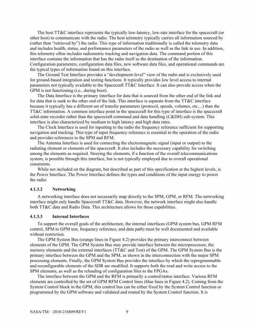
The host TT&C interface represents the typically low-latency, low-rate interface for the spacecraft (or other host) to communicate with the radio. The host telemetry typically carries all information sourced by (rather than “retrieved by”) the radio. This type of information traditionally is called the telemetry data and includes health, status, and performance parameters of the radio as well as the link in use. In addition, this telemetry often includes radiometric tracking and navigation data. The command portion of this interface contains the information that has the radio itself as the destination of the information. Configuration parameters, configuration data files, new software data files, and operational commands are the typical types of information found on this interface.
The Ground Test Interface provides a “development-level” view of the radio and is exclusively used for ground-based integration and testing functions. It typically provides low level access to internal parameters not typically available to the Spacecraft TT&C Interface. It can also provide access when the GPM is not functioning (i.e., during boot).
The Data Interface is the primary interface for data that is sourced from the other end of the link and for data that is sunk to the other end of the link. This interface is separate from the TT&C interface because it typically has a different set of transfer parameters (protocol, speeds, volumes, etc…) than the TT&C information. A common interface point in the spacecraft for this type of interface is the spacecraft solid-state recorder rather than the spacecraft command and data handling (C&DH) sub-system. This interface is also characterized by medium to high latency and high data rates.
The Clock Interface is used for inputting to the radio the frequency reference sufficient for supporting navigation and tracking. This type of input frequency reference is essential to the operation of the radio and provides references to the SPM and RFM.
The Antenna Interface is used for connecting the electromagnetic signal (input or output) to the radiating element or elements of the spacecraft. It also includes the necessary capability for switching among the elements as required. Steering the elements, if a function of the overall telecommunications system, is possible through this interface, but is not typically employed due to overall operational constraints.
While not included on the diagram, but described as part of this specification at the highest levels, is the Power Interface. The Power Interface defines the types and conditions of the input energy to power the radio.
4.1.3.2 Networking A networking interface does not necessarily map directly to the SPM, GPM, or RFM. The networking
interface might only handle Spacecraft TT&C data. However, the network interface might also handle both TT&C data and Radio Data. This architecture allows for those capabilities.
4.1.3.3 Internal Interfaces To support the overall goals of the architecture, the internal interfaces (GPM system bus, GPM RFM
control, SPM to GPM test, frequency reference, and data path) must be well documented and available without restriction.
The GPM System Bus (orange lines in Figure 4.2) provides the primary interconnect between elements of the GPM. The GPM System Bus may provide interface between the microprocessor, the memory elements and the external interfaces (TT&C and Test) of the GPM. The GPM System Bus is the primary interface between the GPM and the SPM, as shown in the interconnection with the major SPM processing elements. Finally, the GPM System Bus provides the interface by which the reprogrammable and reconfigurable elements of the SDR are modified. It supports both the read and write access to the SPM elements, as well as the reloading of configuration files to the FPGAs.
The interface between the GPM and the RFM is primarily a control/status interface. Various RFM elements are controlled by the set of GPM RFM Control lines (blue lines in Figure 4.2). Coming from the System Control block in the GPM, this control bus can be either fixed by the System Control function or programmed by the GPM software and validated and routed by the System Control function. It is

NASA/TM—2010-216809/REV1 10
important to have a hardware-based confirmation and limit-check on the software controlling any RFM elements. The System Control module of the GPM provides this functionality thus keeping the GPM RFM Control bus within operational limits.
The Ground Test Interface (blue lines in Figure 4.2) provides specific control and status signals from different modules or functions to the Ground Test Interface block. These interfaces are used during development and testing to validate the operation of the various radio functions. This interface is also very specific to the implementation and realization of the different modules and is generalized in the Telemetry and Test Interface block as required.
The Frequency Reference Interface provides an important interface between the RFM and the SPM functions. It ties the two modules together in a way that allows for the SDR to implement tracking and navigation functions. The characteristics of this interface are defined by the various amounts of tracking accuracy that are required for the SPM to accomplish. This interface can be as simple as a single, common frequency reference that is conditioned from an outside source and distributed in the least degrading fashion possible to the SPM.
Finally, the data paths are the various streams of bits, symbols, and RF waves connecting the major blocks of the primary data-path. For any particular implementation, the data path or bitstreams are defined by the particular application implemented in the functional blocks. The interface between the RFM and SPM should be well-defined and have characteristics suitable for that level of conversion between the analog and digital domains.
The hardware architecture can be further specified in a manner that is important for implementers to consider and follow, if the implementation dictates the necessity of particular components. Details of the GPM, SPM, and RFM are provided in subsequent sections.
4.2 Module Type Specification
4.2.1 General-Purpose Processing Module (GPM) Figure 4.3 provides a close-up of the GPM detail. The GPM consists of one or more general purpose
or digital signal processing elements and support hardware components, embedded OS, software applications and interfaces to support the configuration, control, and status of the radio. The number of processing elements and the extent of support hardware will vary depending on the mission class processing and data handling requirements from a single system on a chip implementation for smaller mission classes to multiple logical replaceable units (LRUs) for the largest mission classes. Additionally, the fault tolerance requirements can also increase the number of hardware processing elements, support hardware components and interface points required to meet the range of mission classes. The majority of processing functions of the GPM will be under software control and supported by an OS. These are cases, depending on the data handling speeds that require the use specialized support hardware (FPGA or ASIC chips) to alleviate the burden on the processing elements. Such specialized support hardware could include encryption, packet routing, and network processing type functions.
4.2.1.1 GPM Components The GPM contains, as necessary, a GPP and various memory elements as shown in Figure 4.3.
Depending on the particular mission class, not all memory elements are required. The GPP will typically be implemented as a microprocessor, but could take many forms, depending on the mission class. Because the GPM is the primary control component of the radio, it is a required module for an STRS radio. A description of each element in Figure 4.3 is listed below.
The GPP functions include the Operating Environment, the HAL, and potentially application functions. The Operating Environment contains the STRS infrastructure, which provides the functionality for the interfaces defined by the STRS API specification. The OE also contains the Operating System and the POSIX abstraction layer.

NASA/TM—2010-216809/REV1 11
Figure 4.3.—GPM Architecture Details.
The Persistent Memory Storage element holds both the permanent (e.g., programmable read-only
memory (PROM)) and re-programmable code for the GPP element. In today’s technology, this code is implemented using a re-programmable technology such as electrically erasable programmable read-only memory (EEPROM). It is also possible, but not typically qualifiable to implement this code storage in FLASH memory.
The Persistent Memory also provides the re-programmable storage for the SPM FPGA elements (i.e., SPM firmware). The GPM is responsible for programming and scrubbing the SPM FPGAs and therefore contains the appropriate “code” for the FPGAs. This memory block is typically implemented using a non-volatile memory technology such as EEPROM but could, in particular implementations be implemented with PROM technology.
The Work Area Memory element is provided as operational, scratch memory for the GPP element. This memory element is implemented in concert with the GPP element and may contain both data and code, as appropriate for the execution of the radio application running in the GPM.
Finally, the GPM contains a System Control element to control and moderate the GPM System Bus. This element provides the necessary control for the System Bus including the various memory and SPM elements interfaced by the System Bus. In addition, the System Control element provides a validated interface to the RFM hardware via the GPM RFM Control Interface. As the software running on the General Purpose Processing element commands the RFM elements into certain states, those commands are interpreted by the System Control element and validated in a manner that will prevent damaging configurations of the RFM, for example tying the transmit amplifier directly to the receive amplifier, bypassing the diplexer element. This level of validation has to be present in the GPM to RFM Interfaces to prevent the radio from being damaged by a software bug. The System Control element is typically implemented by a non-re-programmable (in flight) FPGA allowing for flexibility between instantiations of a particular implementation.
4.2.1.2 GPM Functions The GPM will provide the overall configuration and control of the STRS architecture and may
include any or all of the following functions:
Management and Control

NASA/TM—2010-216809/REV1 12
– Module discovery – Configuration control – Command, control and status – Fault recovery – Encryption
STRS infrastructure, radio configuration and control – Radio Control – System Management – Application Upload Management – Device Control – Message Center
External Network Interface Processing Internal Data Routing Waveform Data Link Layer
– Medium Access Control (MAC) and Logical Link Control (LLC) layer – Physical layer processing
On board data switch
4.2.1.3 GPM Interfaces TT&C Interface Ground Test Interface Provides programmable general purpose input output (GPIO) to support
– Interrupt source/sink – Application data transfer
Provides control/configuration interfaces – RFM, Antenna, Power Amplifier, and SPM
System bus interface
4.2.1.4 GPM Requirements (STRS-1) An STRS platform shall have a known state after completion of the power-up process. (STRS-2) The STRS Operating Environment shall provide access to platform module’s
diagnostic information via the STRS APIs. (STRS-3) Self diagnostic and fault detection data of a module shall be accessible to the STRS
Operating Environment for collection.
4.2.2 Signal Processing Module (SPM) A SPM is optional for an STRS platform. The SPM may implement the signal processing used to
transform received digital signals into data packets and/or the conversion of data packets into digital signals to transmit. The complexity of this module is optional based on the applications and data rates selected for a mission. The SPM modules contain components and capabilities to manipulate and manage digital signals that require higher processing capabilities than that supplied by the GPM. The firmware architecture describes a common interface for the application on the SPM, as described in Section 6.0. Figure 4.4 illustrates the SPM module details.

NASA/TM—2010-216809/REV1 13
Figure 4.4.—SPM Architecture Details.
4.2.2.1 SPM Components The SPM will initially be implemented primarily with FPGAs, DSPs, reconfigurable processors,
ASICs, and other integrated circuits. However, technologies will change over time, so the specific implementation is left to the platform developer.
It is also anticipated that STRS platforms may use dedicated SPM slices for specific applications and technologies. For example, a dedicated GPS receiver slice can complement the existence of reconfigurable SPM slices in the same radio. The dedicated slice offloads demands on the less specific SPM. If an STRS platform contains an SPM slice, the slice should meet the module interface specifications for control and configuration and have an interface with the GPM via the GPM System Bus and the SPM to GPM Test interface. These two interfaces work in concert to provide a control and reprogramming path to the SPM from the GPM and the application running on the GPM.
4.2.2.2 SPM Functions The SPM performs the digital signal processing functions, which are used to convert symbols to bits
(and vice-versa). These functions are typically implemented on FPGAs, DSPs, or ASICs. It is recommended that these devices be reconfigurable and reprogrammable because this allows for new applications to be implemented on the SDR in the future without a hardware redesign. However, mission specific requirements may dictate that the application be implemented on a non-reprogrammable hardware device.
In addition to the digital signal processing functions, a data formatting function is required to convert blocks of data stored in the data storage element into bitstreams appropriate for encoding into symbols (and vice-versa). In many cases, it is possible to implement the data formatting function in the same device as the digital signal processing function, but that is an implementation detail dependent on the mission class.

NASA/TM—2010-216809/REV1 14
A data storage element is used to provide a queuing buffer between the data interface and the bitstream coders/decoders. This data storage function can be implemented in either volatile or non-volatile memory, depending on the requirements of the mission implementation.
A SPM may implement any or all of the following digital communication functions depending upon the mission waveforms:
Digital Up Conversion.—Interpolation, filtering, and “local oscillator” multiplication of baseband
samples to obtain an IF or RF output sample stream, appropriate for digital-to-analog conversion. This is typically the last transmit function implemented in the SPM, and the output samples are sent to the RFM.
Digital Down Conversion.—Multiplication with “local oscillator”, downsampling, and filtering IF or RF samples to obtain a baseband output sample stream. This is typically the first receive function implemented in the SPM, with input samples coming from the analog-to-digital conversion in the RFM.
Digital Filtering.—Averaging, low-pass, high-pass, band-pass, polyphase, and other filters used for pulse shaping, matched filter, etc. This may overlap with some of the functionality in the Up and Down Conversion.
Carrier Recovery and Tracking.—Retrieval of the waveform carrier within the receive sample stream. Shifting recovered carrier frequency to accommodate local oscillator differences as well as Doppler shifts in the link.
Synchronization (data, symbol, etc.).—Alignment of received samples with symbol and data boundaries. There may some integration with the Digital Down Conversion and Carrier Recovery and Tracking functions.
Forward Error Correction Coding.—Encoding transmit data so that receive data errors may be corrected to some level, enhancing the waveform performance.
Digital Automatic Gain Control.—Scaling of the receive samples to optimize downstream operations.
Symbol Mapping (modulation).—Translating transmit data bits to modulation symbol samples. Data Detection (demodulation).—Translating receive symbol samples to data bits. Spreading/Despreading.—A form of encoding data to obtain certain energy dispersion in the
frequency domain. Scrambling/Descrambling.—A form of encoding data to ensure a certain level of randomness in
the digital data stream, usually for synchronization of the receiver. Encryption/Decryption.—A form of encoding data for security purposes. Data Input/Output (I/O) (high-speed direct from/to source/sink).—Interface for transmit and/or
receive data to come in/out of the module. This may require buffering and some protocol handling.
4.2.2.3 SPM Interfaces The SPM’s external interfaces are shown in Figure 4.4. Interfaces shown include those common to all
module types as well as those specific for the SPM. These SPM specific interfaces may not all be required for some missions. Note that the implementation of these interfaces may combine two or more on one physical transport. For example, the Data Interface and Control & Configuration interfaces may both use the same physical Serial RapidIO connection.
Data I/O to/from RFM.—This is the digital sample stream going to the RFM’s digital to analog converters (DACs) for transmission, and the digital samples from the RFM’s analog to digital converters (ADCs). However, if the DACs and ADCs are preferred to be a part of the SPM, then this interface is replaced with analog baseband or IF signals.
Waveform Control and feedback to RFM.—This interface will be waveform dependent. It may be used, for example, to send feedback to an AGC or control frequency hopping.

NASA/TM—2010-216809/REV1 15
Data Interface external to the radio—High data rate waveforms may need a direct interface to the SPM if the GPM is not designed to handle the data.
System Bus: Data to/from GPM.—This interface exchanges the packetized data for transmission and reception.
Control and Configuration from GPM.—Waveform loads and reconfigurable parameters are managed through this interface.
Test and Status to GPM.—Tests are initiated through this interface by the GPM, and results are returned. This is a more basic interface (electrically and protocol-wise) than the Control and Configuration interface.
Radiometric tracking The HID must contain the characteristics of each reconfigurable device. Reconfigurable capacity is
usually measured by the number of FPGA gates, logic elements, or bytes. This information can be used by future waveform developers to determine the waveforms that can be implemented on a given platform.
4.2.2.4 SPM Requirements (STRS-4) The STRS platform developer shall describe in the HID document, the behavior and
capability of each major functional device or resource available for use by waveforms, services, or other applications (e.g., FPGA, GPP, DSP, memory), noting any operational limitations.
(STRS-5) The STRS platform developer shall describe in the HID document, the reconfigurability behavior and capability of each reconfigurable component.
The description of the behavior and capability of functional devices available to application
developers or reconfigurable components may include device type, processing capability, clock speeds, memory size(s), types(s), and speed(s), noting any constraints.
4.2.3 Radio Frequency Module (RFM) The RFM handles the conversion to and from the carrier frequency, providing the SPM and/or the
GPM with digital baseband or IF signals, and the transmission and reception equipment with RF to support the SPM and GPM functions. Its components typically include DACs, ADCs, RF switches, up-/down-converters, diplexer, filters, LNAs, power amplifiers, etc. Current and near term RF technologies cannot be expected to allow multi-band operation using a single channel RFM and thus multi-band radios will require the use of multiple RFM slices. The RFM provides a band of frequency tunability on each slice. This tunability can be software controlled through the provided interfaces.
The RF module handles the interfaces that control the final stage of transmission or first stage of reception of the wireless signals, including antennas, optical telescopes, steerable antennas, external power amplifiers, diplexers, triplexers, RF switches, etc. These external radio equipment components would otherwise be integrated with the RFM except for the physical size and location constraints for transmission and reception. The interfaces are primarily the associated control interfaces for these components. The RFM HID encompasses the control and interface mechanism to the external components. The focus of the RF HID is to provide a standardized interface to the control of each of these devices, to synchronize the operation of the radio with any of these devices.
The other primary capability of the RFM is the conditioning and distribution of the frequency reference as defined by the Frequency Reference Interface. This provides a common reference for the RFM and SPM modules to enable the tracking and navigation functionality required of SDRs.

NASA/TM—2010-216809/REV1 16
Figure 4.5.—RFM Architecture Details.
4.2.3.1 RFM Functions The RFM transforms the antenna signal to/from a signal usable to the radio. The RFM functions are
likely to include: Frequency Conversion and Gain Control Analog Filtering Analog-to-Digital and Digital-to-Analog conversion Radiometric tracking
4.2.3.2 RFM Components The RFM can be implemented with a variety of integrated circuits. The control of these circuits can
be implemented with a variety of different component technologies including ASICs, discrete electronics, programmable logic devices including FPGAs and DSPs, or even microprocessors. The choice of technologies is left up to the developer of the particular implementation. It is expected that the control of the devices will become more sophisticated over time, and the level of control will increase, resulting in more complex control circuitry and logic devices being used.
4.2.3.3 RFM Interface External RF interface(s) to the radio Provides read and write access to interface registers to monitor and perform control, status, and
failure and fault recovery functions (e.g., via RS-422 or Space Wire). – Control (power level tunability, frequency tunability, antenna parameter tunability, etc.)
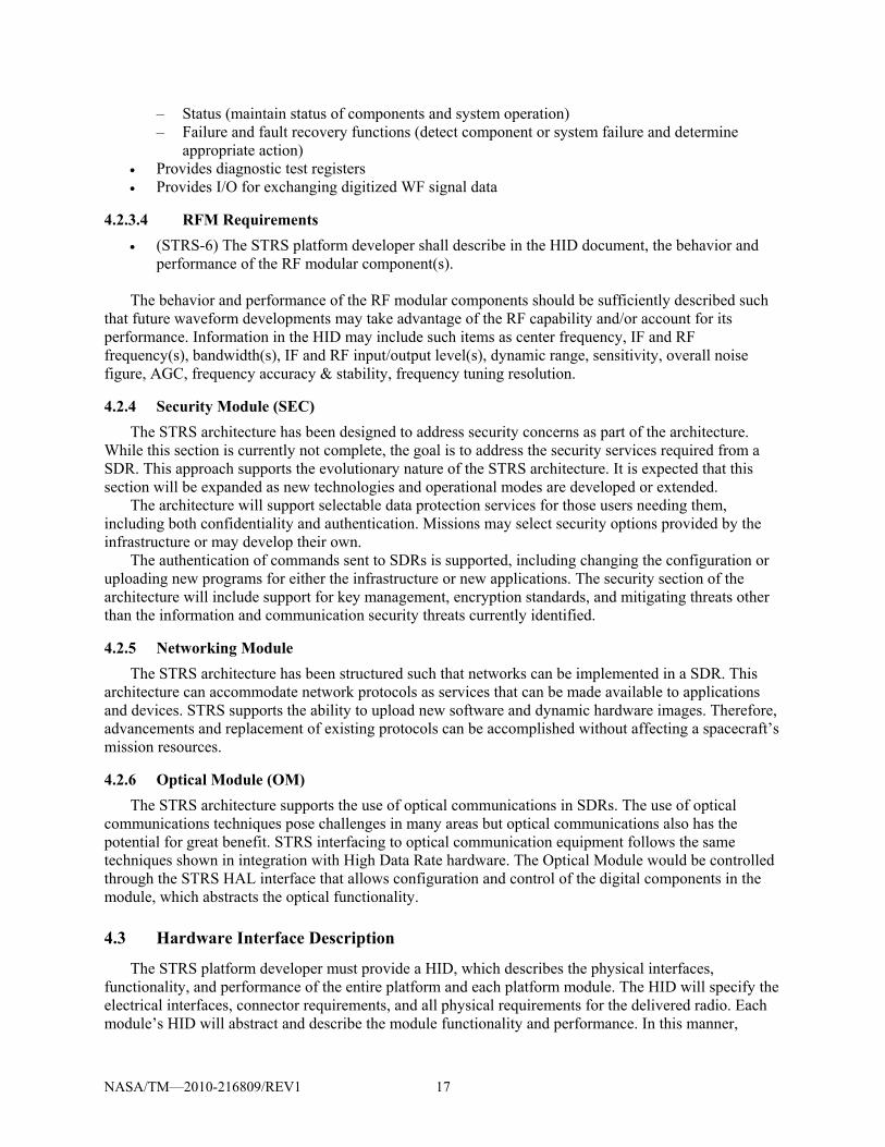
NASA/TM—2010-216809/REV1 17
– Status (maintain status of components and system operation) – Failure and fault recovery functions (detect component or system failure and determine
appropriate action) Provides diagnostic test registers Provides I/O for exchanging digitized WF signal data
4.2.3.4 RFM Requirements (STRS-6) The STRS platform developer shall describe in the HID document, the behavior and
performance of the RF modular component(s).
The behavior and performance of the RF modular components should be sufficiently described such that future waveform developments may take advantage of the RF capability and/or account for its performance. Information in the HID may include such items as center frequency, IF and RF frequency(s), bandwidth(s), IF and RF input/output level(s), dynamic range, sensitivity, overall noise figure, AGC, frequency accuracy & stability, frequency tuning resolution.
4.2.4 Security Module (SEC) The STRS architecture has been designed to address security concerns as part of the architecture.
While this section is currently not complete, the goal is to address the security services required from a SDR. This approach supports the evolutionary nature of the STRS architecture. It is expected that this section will be expanded as new technologies and operational modes are developed or extended.
The architecture will support selectable data protection services for those users needing them, including both confidentiality and authentication. Missions may select security options provided by the infrastructure or may develop their own.
The authentication of commands sent to SDRs is supported, including changing the configuration or uploading new programs for either the infrastructure or new applications. The security section of the architecture will include support for key management, encryption standards, and mitigating threats other than the information and communication security threats currently identified.
4.2.5 Networking Module The STRS architecture has been structured such that networks can be implemented in a SDR. This
architecture can accommodate network protocols as services that can be made available to applications and devices. STRS supports the ability to upload new software and dynamic hardware images. Therefore, advancements and replacement of existing protocols can be accomplished without affecting a spacecraft’s mission resources.
4.2.6 Optical Module (OM) The STRS architecture supports the use of optical communications in SDRs. The use of optical
communications techniques pose challenges in many areas but optical communications also has the potential for great benefit. STRS interfacing to optical communication equipment follows the same techniques shown in integration with High Data Rate hardware. The Optical Module would be controlled through the STRS HAL interface that allows configuration and control of the digital components in the module, which abstracts the optical functionality.
4.3 Hardware Interface Description
The STRS platform developer must provide a HID, which describes the physical interfaces, functionality, and performance of the entire platform and each platform module. The HID will specify the electrical interfaces, connector requirements, and all physical requirements for the delivered radio. Each module’s HID will abstract and describe the module functionality and performance. In this manner,

NASA/TM—2010-216809/REV1 18
application developers will know the features and limitations of the platform for their applications. Once the radio has been procured, NASA will have the knowledge to procure or produce new or additional modules using HID information. Also, future module replacement or additions will be possible without designing a new platform. For example, a Security Module may be added that wasn’t originally planned, or a follow-on mission may use a different frequency band and only require an RFM change.
In addition to the GPM, SPM, and RFM HID descriptions and requirements stated within each module section, the following interface descriptions and requirements are also specified for an STRS platform.
(STRS-7) The STRS platform provider shall describe in the HID document, the interfaces that are provided to and from each modular component of the radio platform.
The specific modular components or hardware slices of an STRS radio will vary among different
implementations. The STRS Platform developer or integrator is expected to describe each modular component and their respective physical and logical interfaces as described in this section. Table 4.1 provides typical interface characteristics that should be included when identifying external interfaces or internal interfaces between modules for STRS.
TABLE 4.1.—STRS MODULE INTERFACE CHARACTERIZATION
Parameter Description/comments
Name Interface Name (data, control, DC power, RF, security, etc) Interface type Point to point, point-multipoint, multipoint, serial, bus, other Implementation level Component, module, board, chassis, remote node Reference documents/standards Applicable documents for interface standards or description of custom interfaces Note/constraints Variances from standards, physical and logical functional limitations Transfer speed Clock speed, throughput speed Signal definition Description of functionality and intended use
Physical implementation
Technology For example, GPP, DSP, FPGA, ASIC and description Connectors Model number, pin out (incl. unused pins) Data plane Width, speed, timing, data encoding, protocols Control plane Control signals, control messages or commanding, interrupts, message protocol
Functional implementation
Models Data plane model, control plane model, test bench model Power Voltages, currents, noise, conducted immunity, susceptibility APIs Custom or standard, particular to OS environment Software Device drivers, development environment & tool chain
Logical implementation
Addressing Method, schemes Channels Open, close Connection type Forward, terminate, test
4.3.1 Control and Data Interface The control and data communications buses/links between modules within the radio will be described
by the STRS platform developer to the level of detail necessary to facilitate integration of another vendor’s module. If modules communicate using Institute of Electrical and Electronic Engineers IEEE-1394, for example, this will be specified in the HID with appropriate connector and pinout information.

NASA/TM—2010-216809/REV1 19
Any non-standard protocols used must also be specified which in some cases may be handled by the software HAL. Module interfaces will be completely described, including any unused pins.
(STRS-8) The STRS platform provider shall describe in the HID document, the control,
telemetry, and data mechanisms of each modular component (i.e., how to program or control each modular component of the platform, and how to use or access each device or software component, noting any proprietary aspects).
Besides the interface descriptions already provided for each modular component, developers should
provide specific information necessary to future application developers of how to interact with the command and control aspects of the platform. The description of the control, telemetry and data mechanism of each modular component shall facilitate porting of application software to the platform.
4.3.2 DC Power Interface The DC power interface description for the radio has two parts; 1) the platform as a supplier to the
various modules, and 2) the power consumption of the different modules, if multiple modules are provided. Table 4.2 shows an example listing of a platform DC power interface. There are four distinct sets of power requirements for the platform shown. Modules delivered with the radio, as well as those built by other vendors, must specify the needed voltages, currents, and connections. Voltages must be specified with a max/min tolerance, and associated currents must be specified with nominal and maximum values. Connectors for DC power must be specified, including pinouts. If power is routed through a multi-purpose connector, such as a backplane connector, then the pins actually used must be documented. Power is a limited commodity for most missions, and understanding the radio platform power needs is critical.
TABLE 4.2.—EXAMPLE—DC POWER INTERFACE (PLATFORM SUPPLIED)
Parameter Values
Voltage available –15 V +2.5 V +5 V +15 V
Max. current/chassis (platform) 2 A 1.7 A 3 A 2 A
Max. current/slot (module) 1 A 1 A 1 A 1 A
Backplane supply pins 17, 19 59, 61 44, 46, 48 21, 23
Backplane return pins 18, 20 60, 62 43, 45, 47 22, 24
Connector type
Voltage ripple 100 mVpp 1 mVpp 5 mVpp 100 mVpp
Notes: Slot 1 & 2 only Slot 1 & 2 only
(STRS-9) The STRS platform developer shall describe in the HID document, the behavior and
performance of any power supply or power converter modular component(s).
4.3.3 Thermal and Mechanical Interface The power consumption and resulting heat generation of a reprogrammable FPGA will vary based on
the amount of logic used and the clock frequency(s). The power consumption may not be constant for each possible waveform that can be loaded on the platform. The platform provider should document the maximum allowable power available and thermal dissipation of the FPGA(s) based on the maximum allowable thermal constraints of FPGA(s) of the platform. For human spaceflight environments, touch temperature requirements may limit dissipation further; therefore, these reductions must be factored into the given dissipation limits.

NASA/TM—2010-216809/REV1 20
5.0 Applications 5.1 Application Implementation
As shown in Figure 5.1, an example STRS platform consists of one or more GPMs with GPPs, and optionally one or more Signal Processing Modules containing DSPs, FPGAs, and ASICs. Application (waveform and service) components loaded and executed on these modules provide the signal processing algorithms necessary to generate or receive RF signals. To aid portability, the applications must use the appropriate infrastructure APIs to access platform services. Using “direct to hardware” access instead would increase the effort to port the application to a platform with different hardware. The STRS infrastructure provides the APIs and services necessary to load, verify, execute, change parameters, terminate, or unload an application. The STRS infrastructure utilizes the hardware abstraction layer to abstract communications with the specialized hardware, while the HID physically identifies how modules are integrated on a platform.
(STRS-10) An STRS application shall use the infrastructure STRS API and POSIX API for access to platform resources.
(STRS-11) The STRS infrastructure shall use the STRS Platform HAL APIs to communicate with application components on the platform specialized hardware via the physical interface defined by the platform developer.
5.2 Application Selection
Platform developers have the option of providing telemetry values to indicate what types of applications are installed. The method for selecting the application will be a combination of the platform’s capabilities as well as the specification defined by the STRS Command and Telemetry Interface in Section 8.0.
STRS specifies two types of configuration files: a platform specific component, and an application specific component. An application specific configuration file specifies information used to initialize an STRS application. Section 9.0 contains further discussion of platform and application configuration files.
Figure 5.1.—Waveform Component Instantiation.
H I D
Operating Environment withPOSIX Compliant RTOS
General-purpose Processing Module
Signal Data
Signal Processing Module
Signal
H I D
H I D
HALBoard
Support Package
STRS APIs Waveform
Control and Services
STRS Infrastructure
STRS APIs Waveform
Component A
Signal Processing Module
Signal Data Waveform
ComponentC
Waveform Component
D
Waveform Component
B

NASA/TM—2010-216809/REV1 21
5.3 Navigation Services
The STRS architecture allows STRS radios to provide radiometric tracking and navigation services that are integrated with communication services. Radiometric tracking is the process of measuring characteristics of radio signals that have been transmitted (potentially over several legs) in order to extract information relating to the signal’s change in frequency and/or time of transit. A radio has the fundamental component needed for tracking—a radio signal. The SDR simplifies the navigation architecture because it minimizes mass, power, volume requirements while maximizing flexibility. An SDR provides the flexibility to respond to different mission phase requirements, and the flexibility to respond to dynamic application requirements where signal structures may change. This is the fundamental thesis for considering implementation of an SDR with tracking and navigation functionality.
5.4 Application Repository Submissions
The STRS architecture facilitates the use of reusable and highly reliable applications. Highly reliable and reusable applications require good coding practices, good documentation, and thorough testing. The documentation and application artifacts are to be submitted to the NASA STRS Repository. The goal of the NASA STRS Repository is to reduce future application development time and porting time since application developers will have access to validated code. The STRS Repository is an archive of the developed firmware and software for the various applications. The repository allows application developers access to existing STRS application artifacts that have been populated by NASA and STRS application developers. The documentation of STRS application behavior should include the application developer’s implementation of the STRS application-Provided application control API methods as described in Section 7.3.1
(STRS-12) Application development artifacts shall be submitted to the NASA STRS Repository. The use will be subject to the appropriate license agreements. The application development artifacts shall include, as a minimum, the following: – High level system or component software model – Documentation of application firmware external interfaces (e.g., signal names and
descriptions, signal polarity and format, timing constraints of signals) – Documentation of STRS application behavior – Application function sources (e.g., C, C++, header files, VHDL, Verilog) – Application libraries, if applicable (e.g., EDIF, DLL) – Documentation of application development environment and tool suite – Test plan and results documentation – Identification of Flight Software Development Standards used
6.0 Firmware Architecture Firmware is embedded in a hardware device, such as an FPGA or a DSP. Firmware is distinguished
from software residing in a general purpose processor which is generally easier to change. The firmware architecture will address the use of firmware from the design and development, through testing and verification, and operations. It will address aspects of model based design techniques and design for space environment applications.
Proper testing of firmware is critical in the development of reliable and reusable code. Development tools that enable early development and testing should be used so that problems can be identified and resolved early in the SDR life cycle. Many real-world signal degradations and SEUs can be simulated to identify potential issues with the waveform and waveform functions early in development, even before hardware is available. Application firmware should be implemented in a modular fashion with clear interfaces to enable individual application component simulations and incremental testing.

NASA/TM—2010-216809/REV1 22
The firmware architecture supports the modeling of STRS firmware applications at the system, subsystem, and function levels. Model-based design techniques aid in the development of modular application functions. Application firmware development models done in a platform (or target) independent manner aid in application reuse and portability. A platform independent model design can be used to target different platforms. Platform independent model design flows might include high level models combined with manual code writing or the use of platform independent models to auto generate code. These design flows can be employed to significantly reduce the porting effort.
Application portability should be considered in all facets of the design process from concept to implementation to testing. The coding technique of the application is also essential to reduce the application porting effort. Having defined syntax standards for hardware descriptive languages (e.g., Verilog, VHDL) makes them appear to be easily portable across devices and software synthesizers, but this is an incorrect assumption. There are many things that can make hardware descriptive languages hard to port. For example, the use of device specific fixed hardware logic on the FPGA will decrease the portability. The use of specialized hardware may be required to meet the timing constraints of the application; however, the application developer should document any application function that uses the specialized hardware so that the effort to port the application function(s) can be determined. Non-boolean type logic such as clock generation can also reduce portability. One method to decrease the porting effort would be to create a module that does the clock generation from which the rest of the application functions receive the necessary clock(s).
Development of firmware for STRS radios should include provisions for mitigating space environmental effects such as SEUs. Near term application of static random access memory (SRAM)-based FPGAs may require triple mode redundancy (TMR), configuration memory scrubbing, and other mitigation techniques depending on the intended mission environment and desired reliability. Commercial design tools are becoming available to aid in this process and some newer FPGAs have versions available with embedded TMR.
A key feature of SDRs is that they can be reconfigured after deployment. The capability to load new applications and services will benefit missions in several ways, including using one SDR (instead of several separate radios) to handle different applications for various phases of a mission, some planned and some unplanned. An STRS platform should receive STRS application software and firmware updates after deployment.
6.1 Specialized Hardware Interfaces
Standardizing the interface from the waveform applications on the GPP to the portion of the waveform in the specialized processing hardware such as FPGAs or DSPs is intended to provide commonality among different STRS platforms, and to aid portability of application functional components implemented in firmware. Figure 6.1 depicts the high level interface relationship between a GPM, SPM, and RFM modules in an STRS radio.
The firmware architecture provides commonality among different STRS platforms when executing firmware applications. The common platform operations include the control and the instantiation of an application. In addition, the architecture supports the reconfiguration of the application instantiated in different hardware devices, depending on the platform capabilities. The reconfiguration should include parameter changes of installed applications and uploading new applications after deployment.
The application accepts configuration and control commands from the GPM and uses STRS APIs that interface to the device drivers associated with the SPM and RFM modules. The device drivers communicate via the HAL on the GPM that abstracts the physical interface specification described in the HID in transferring command and data information between the modules.
For FPGAs on the SPM, the interface to the application is through a platform specific wrapper. The platform specific wrapper accepts command and data information from the GPM and provides them to the application. The platform specific wrapper also abstracts details of the platform from the application developer, such as pinout information. The platform specific wrapper should also provide clock

NASA/TM—2010-216809/REV1 23
generation, signal registering, and synchronization functions, and any other non-waveform specific functions the platform requires. Documentation of the platform specific wrapper is necessary so that application developers can interface applications to the platform.
(STRS-13) If the STRS application has a component resident in an SPM (e.g., FGPA firmware), then it shall accept configuration and control commands from the STRS Operating Environment.
(STRS-14) The STRS SPM developer shall provide a platform specific wrapper for each user-programmable FPGA on the SPM, which performs, as a minimum, the following functions: – Provides an interface for command and data from the GPM to the waveform application – Provides the platform specific pinout for the application developer. This may be a complete
abstraction of the actual FPGA pinouts with only waveform application signal names provided.
(STRS-15) The STRS SPM developer shall provide documentation on the firmware interfaces of the platform specific wrapper for each user-programmable FPGA on the SPM, which describe, as a minimum, the following: – Signal names and descriptions – Signal polarity and format – Signal timing constraints of all signals – Clock generation and synchronization methods – Signal registering methods – Identification of development tool set used
STRS Firmware
Interface Concepts—v1.02 FPGA-based generic WF
Figure 6.1.—High-level Software and Firmware Waveform Applications Interfaces.

NASA/TM—2010-216809/REV1 24
6.2 Proposed Firmware Architecture Extension
One goal of the STRS architecture is to promote application reuse among multiple software defined radios. Many space domain applications are designed to run in the specialized signal processing hardware. The STRS architecture is currently incomplete in defining a standard for designing applications in the SPM hardware. Therefore, the STRS architecture will be extended in the future to encompass application development in firmware. These extensions will include a firmware developer interface (FDI) that abstracts the application running on a FPGA from devices external to a FPGA and a standard interface between application functions running inside a FPGA. The extension of STRS to the firmware will promote easier application reconfiguration and reuse.
STRS Firmware Interface Concepts—draft FPGA-based generic WF
Figure 6.2.—Proposed Firmware Architecture Extension
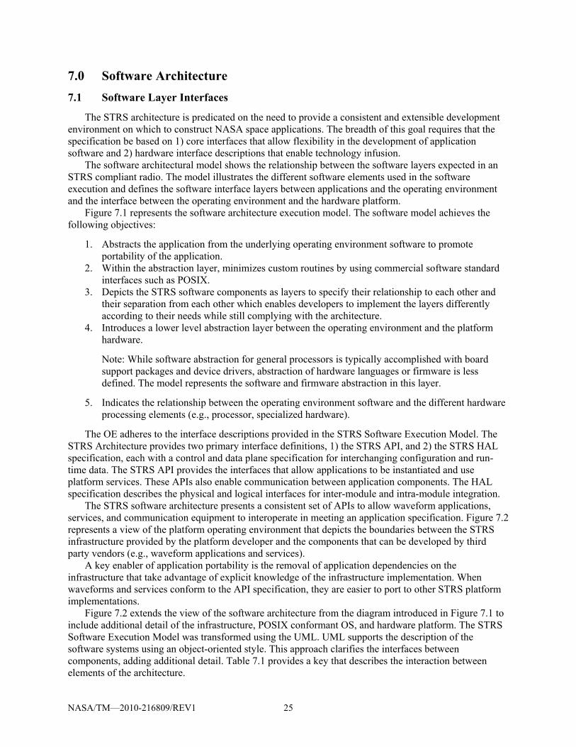
NASA/TM—2010-216809/REV1 25
7.0 Software Architecture 7.1 Software Layer Interfaces
The STRS architecture is predicated on the need to provide a consistent and extensible development environment on which to construct NASA space applications. The breadth of this goal requires that the specification be based on 1) core interfaces that allow flexibility in the development of application software and 2) hardware interface descriptions that enable technology infusion.
The software architectural model shows the relationship between the software layers expected in an STRS compliant radio. The model illustrates the different software elements used in the software execution and defines the software interface layers between applications and the operating environment and the interface between the operating environment and the hardware platform.
Figure 7.1 represents the software architecture execution model. The software model achieves the following objectives:
1. Abstracts the application from the underlying operating environment software to promote portability of the application.
2. Within the abstraction layer, minimizes custom routines by using commercial software standard interfaces such as POSIX.
3. Depicts the STRS software components as layers to specify their relationship to each other and their separation from each other which enables developers to implement the layers differently according to their needs while still complying with the architecture.
4. Introduces a lower level abstraction layer between the operating environment and the platform hardware.
Note: While software abstraction for general processors is typically accomplished with board support packages and device drivers, abstraction of hardware languages or firmware is less defined. The model represents the software and firmware abstraction in this layer.
5. Indicates the relationship between the operating environment software and the different hardware processing elements (e.g., processor, specialized hardware).
The OE adheres to the interface descriptions provided in the STRS Software Execution Model. The STRS Architecture provides two primary interface definitions, 1) the STRS API, and 2) the STRS HAL specification, each with a control and data plane specification for interchanging configuration and run-time data. The STRS API provides the interfaces that allow applications to be instantiated and use platform services. These APIs also enable communication between application components. The HAL specification describes the physical and logical interfaces for inter-module and intra-module integration.
The STRS software architecture presents a consistent set of APIs to allow waveform applications, services, and communication equipment to interoperate in meeting an application specification. Figure 7.2 represents a view of the platform operating environment that depicts the boundaries between the STRS infrastructure provided by the platform developer and the components that can be developed by third party vendors (e.g., waveform applications and services).
A key enabler of application portability is the removal of application dependencies on the infrastructure that take advantage of explicit knowledge of the infrastructure implementation. When waveforms and services conform to the API specification, they are easier to port to other STRS platform implementations.
Figure 7.2 extends the view of the software architecture from the diagram introduced in Figure 7.1 to include additional detail of the infrastructure, POSIX conformant OS, and hardware platform. The STRS Software Execution Model was transformed using the UML. UML supports the description of the software systems using an object-oriented style. This approach clarifies the interfaces between components, adding additional detail. Table 7.1 provides a key that describes the interaction between elements of the architecture.

NASA/TM—2010-216809/REV1 26
Figure 7.1.—STRS Software Execution Model.
Figure 7.2.—STRS Layered Structure in UML.
Figure 7.2 extends the view of the software architecture from the diagram introduced in Figure 7.1 to include additional detail of the infrastructure, POSIX conformant OS, and hardware platform. The STRS Software Execution Model was transformed using the UML. UML supports the description of the software systems using an object-oriented style. This approach clarifies the interfaces between components, adding additional detail. Table 7.1 provides a key that describes the interaction between elements of the architecture.

NASA/TM—2010-216809/REV1 27
Figure 7.3 describes the elements of the detailed operating environment depicted in Figure 7.1. In the case that the OS does not support the POSIX subset, the missing functionality will be required to be implemented in the STRS infrastructure. The diagram also illustrates the inclusion of a POSIX abstraction layer in the infrastructure. As a note, this abstraction is not only for a non-POSIX OS, but the POSIX abstraction layer would implement any POSIX functions required but not implemented by the OS.
In Figure 7.3 the arrows identify interface dependencies and isolations. The Waveform Applications will not directly call the driver API but must use the provided STRS API, thus providing the “abstraction layer” that helps isolate the application from the platform.
TABLE 7.1.—STRS ARCHITECTURE SUBSYSTEM KEY Diagram Element Name Explanation
Composition A contains X items of type B. B is a part of the aggregate A. B does not exist independently from A. X may be a number or a range from m to n depicted by “m..n” where n may be an asterisk to indicate no upper limit.
Generalization or
Inheritance
B is derived from A. B is a kind of A. B inherits all the properties of A. A is a more general case of B. Since B is more specialized, it frequently contains additional attributes and/or functionality than A.
Interface C is an interface provided by B; that is, C contains the means to invoke behavior that resides in B. A uses the interface C to access B.
Association A is associated with B. The optional description “uses” indicates that A is associated with B such that A “uses” B.
Association D acts upon A and A responds to D. Or possibly vice versa. D is normally an actor outside the system.

NASA/TM—2010-216809/REV1 28
Figure 7.3.—STRS Operating Environment.
In Table 7.2, the different layers of the STRS software model are described.

NASA/TM—2010-216809/REV1 29
TABLE 7.2.—STRS SOFTWARE COMPONENT DESCRIPTIONS Layer Description
Waveform Application/Services
Waveform application/services provide the radio GPP functionality using the STRS infrastructure.
STRS infrastructure The STRS infrastructure implements the behavior and functionality identified by the STRS API as well as other required radio functionality.
STRS API The STRS API provides consistent interfaces for the STRS infrastructure to control applications and services, and for the applications and services to access STRS infrastructure services.
APP API The APP API is the interface implemented by waveforms and services whose functions are used by the STRS infrastructure.
POSIX Abstraction Layer
An optional interface (see Figure 7.4) that provides POSIX OS services to the waveform application and services on platforms with an OS that does not provide POSIX interfaces.
Radio Control Services
Responsible for the handling the radio commands and telemetry for STRS. Applications use STRS interface to communicate telemetry and receive commands from flight computer.
Logical HAL Interfaces (HAL API)
Provides the Device Control interfaces that are responsible for all access to the hardware devices in the STRS radio. The Hardware Abstraction Layer API is the interface to the software drivers and BSP that communicates with the hardware.
POSIX API The STRS defines a minimum POSIX Application Environment Profile (AEP) for the allowed OS services. The POSIX AEP can be implemented by either a POSIX conformant OS, or by a POSIX Abstraction Layer in conjunction with a non-conformant OS.
OS The operating system that supports the POSIX API and other OS services. The POSIX Abstraction Layer will provide application with a consistent AEP interface that is mapped into the chosen OS functions.
POSIX OS STRS POSIX AEP conformant operating system.
Direct Service Support
This layer identifies the ability for the STRS infrastructure to have a direct interface to the hardware drivers on the platform.
HW Drivers The hardware drivers provide the platform independence to the software and infrastructure by abstracting the physical hardware interfaces into a consistent Device Control API.
Physical HAL This specification provides the physical medium as well as interconnections between modules in the STRS Radio.
Registered OS Services
Services that are integrated with the chosen OS to provide services such as MAC layer interface to physical Ethernet hardware.
Driver API OS supplied APIs are abstracted from applications via the Device Control API.
BSP The BSP is the software that implements the device drivers and parts of the kernel for a specific piece of hardware. It provides the hardware abstraction of the GPM module for the POSIX-compliant Operating System. A BSP contains source files, binary files, or both. A BSP contains an OEM Adaptation Layer (OAL), which includes a boot loader for initializing the hardware and loading the operating system image. Essentially the OAL is all of the software that is hardware specific. The OAL is actually compiled and linked into the embedded operating system.
HW IO Interfaces Device drivers have been created for these physical interfaces.
GPM General-purpose Processing Module on which the STRS infrastructure executes.
Specialized Hardware Physical layer of the hardware modules existing on the STRS Platform.
The difference between a POSIX conformant OS and a non-conformant OS is illustrated in Figure 7.4. On the left side, the POSIX AEP is provided entirely by the OS. The POSIX APIs are included in those for the OS. On the right side, the OS is not POSIX AEP conformant but is partially compliant. The POSIX AEP is shown in two parts. One part shows the POSIX APIs that are included in the OS. The other part shows the part of the POSIX AEP that is not provided by the OS but must be provided as the POSIX Abstraction Layer. The STRS Operating Environment includes a POSIX PSE51 conformant OS or POSIX abstraction layer for missing APIs.

NASA/TM—2010-216809/REV1 30
Figure 7.4.—POSIX Compliant versus Conformant.
Figure 7.5.—STRS infrastructure.
7.2 Infrastructure
The STRS infrastructure is part of the OE and provides the functionality for the interfaces defined by the STRS API specification. The infrastructure exposes a standard set of method names to the applications to facilitate portability. Although the STRS infrastructure may use any combination of POSIX, OS, BSP functions, or other infrastructure methods to implement a radio function, which may vary on different platforms, the STRS API will be the same to allow portability. The STRS API is the well-defined set of interfaces used by STRS applications to access specific radio functions or used by the infrastructure to control the applications.
The infrastructure is composed of multiple subsystems that interoperate to provide the functionality to operate the radio. The components shown in Figure 7.5 represent the high level subsystems and services

NASA/TM—2010-216809/REV1 31
needed to control STRS applications within the radio platform. These services are provided by the platform infrastructure and support applications as they execute within the radio platform. The infrastructure functions will include fault management techniques, which are necessary to increase radio robustness and support mission dependent requirements. In order to support one of the primary objectives of STRS (upgradeability), an STRS radio should be capable of receiving updated versions of the OE to support applications developed for newer versions of the STRS architecture standard after deployment.
7.3 STRS APIs
The STRS APIs provide an open software specification for the application engineer to develop STRS applications. The goal is to have a standard API available to cover all application program requirements so that the application programs can be reused on other hardware systems with minimal porting effort and cost of the application software (and firmware), and increased reliability. Size, weight, and power constraints may limit the functionality of the radio by imposing a trade-off among a) the size of the API implementation, b) the size of other internal operations, and c) the size of the waveforms and services. The size of the selected GPP must be sufficient to contain the operating system, STRS infrastructure, and the appropriate portion of the waveforms and services to implement the required mission functionality, along with sufficient margin to support software upgrades. The STRS APIs are defined to support internal radio commands. The external interface commands, described in Section 8.0, often use the internal commands defined by the STS APIs to accomplish normal radio operations.
The API layer specification decouples the intellectual property rights of platform, application, and module developers. The API layer allows development and interoperability of different radio aspects while protecting the investment of the developers. The definition of APIs is based on a set of sequence diagrams derived from the use cases identified in the STRS Software Architecture Concepts and Analysis document Appendix B.
A handle ID is an identifier used to control access to applications and resources such as other applications, devices, files, or message queues. Special purpose handle ID for errors include: STRS_ERROR_QUEUE, STRS_WARNING_QUEUE, and STRS_FATAL_QUEUE. A non-fatal error is a correctable condition such that the application is usable when the error is corrected. A warning is an indication of an impending error that is correctable if action is taken. A fatal error is a condition where the application is subsequently not usable.
7.3.1 STRS Application-provided Application Control API A key aspect of a software-architecture is the definition of the APIs that are used to facilitate software
configuration and control of the target platform. The philosophy on which the STRS architecture is based avoids the conflict between open architecture and proprietary implementations by specifying a minimum set of APIs that are used to execute waveform applications and deliver data and control messages to installed hardware components.
The following APIs exhibit similar functionality to a resource interface in the OMG/SWRADIO or Software Communications Architecture (SCA). The APIs could be implemented using the same Platform-Independent Model (PIM) as the OMG/SWRADIO or SCA and a different Platform-Specific Model (PSM) from the OMG/SWRADIO or SCA. The APIs are further grouped similar to the OMG/SWRADIO as shown in Figure 7.6.
As shown in Figure 7.6, an STRS application implementation (e.g., waveform) is derived from the STRS_ApplicationControl API, the STRS_Source API when implementing APP_Read, and the STRS_Sink API when implementing APP_Write. The interfaces are implemented in groups so that STRS_ApplicationControl is derived from the STRS_LifeCycle, STRS_PropertySet, STRS_TestableObject, STRS_ControllableComponent, and STRS_ComponentIdentifier interfaces.
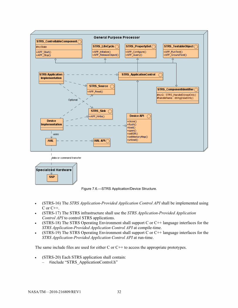
NASA/TM—2010-216809/REV1 32
Figure 7.6.—STRS Application/Device Structure.
(STRS-16) The STRS Application-Provided Application Control API shall be implemented using C or C++.
(STRS-17) The STRS infrastructure shall use the STRS Application-Provided Application Control API to control STRS applications.
(STRS-18) The STRS Operating Environment shall support C or C++ language interfaces for the STRS Application-Provided Application Control API at compile-time.
(STRS-19) The STRS Operating Environment shall support C or C++ language interfaces for the STRS Application-Provided Application Control API at run-time.
The same include files are used for either C or C++ to access the appropriate prototypes.
(STRS-20) Each STRS application shall contain:
– #include “STRS_ApplicationControl.h”

NASA/TM—2010-216809/REV1 33
(STRS-21) The STRS platform developer shall provide an “STRS_ApplicationControl.h” that contains the method prototypes and, for C++, the class definition for the base class STRS_ApplicationControl.
(STRS-22) If the STRS Application-Provided Application Control API is implemented in C++, the STRS application class shall be derived from the STRS_ApplicationControl base class.
For example, the MyWaveform.h file should contain a class definition of the form:
class MyWaveform : public STRS_ApplicationControl {…}; A sink is used for a push model of passing data: to write data to the waveform, device, file, or queue.
(STRS-23) If the STRS application provides the APP_Write method, the STRS application shall contain: – #include “STRS_Sink.h”
(STRS-24) The STRS platform developer shall provide an “STRS_Sink.h” that contains the method prototypes and, for C++, the class definition for the base class STRS_Sink.
(STRS-25) If the STRS Application-Provided Application Control API is implemented in C++ AND the STRS application provides the APP_Write method, the STRS application class shall be derived from the STRS_Sink base class.
For example, the MyWaveform.h file should contain a class definition of the form:
class MyWaveform : public STRS_ApplicationControl, public STRS_Sink {…};
A source is used for a pull model of passing data: to read data from the waveform, device, file, or queue.
(STRS-26) If the STRS application provides the APP_Read method, the STRS application shall contain: – #include “STRS_Source.h”
(STRS-27) The STRS platform developer shall provide an “STRS_Source.h” that contains the method prototypes and, for C++, the class definition for the base class STRS_Source.
(STRS-28) If the STRS Application-Provided Application Control API is implemented in C++ AND the STRS application provides the APP_Read method, the STRS application class shall be derived from the STRS_Source base class.
For example, the MyWaveform.h file should contain a class definition of the form:
class MyWaveform : public STRS_ApplicationControl, public STRS_Source {…};
If both APP_Read and APP_Write are provided in the same waveform, the C++ class will be derived from all three base classes named in requirements (STRS-22, STRS-25, and STRS-28). For example, the MyWaveform.h file should contain a class definition of the form: class MyWaveform : public STRS_ApplicationControl, public STRS_Sink, public STRS_Source {…};

NASA/TM—2010-216809/REV1 34
The following state diagram, Figure 7.7, shows that an STRS application can have various states during execution. The files for the STRS application must be accessible before execution can begin.
STRS_InstantiateApp causes the configuration file to be parsed and APP_Instance or the
constructor to be called thereby beginning execution and placing the STRS application in the STRS_APP_INSTANTIATED state.
STRS_Initialize calls APP_Initialize on the appropriate STRS application. APP_Initialize transitions the STRS application to the STRS_APP_STOPPED state upon
successful completion. STRS_Start calls APP_Start on the appropriate STRS application. APP_Start transitions the STRS application from the STRS_APP_STOPPED state to the
STRS_APP_RUNNING state upon successful completion. STRS_Stop calls APP_Stop on the appropriate STRS application. APP_Stop transitions the STRS application from the STRS_APP_RUNNING state to the
STRS_APP_STOPPED state upon successful completion. The FAULT state is set by the STRS application, but any recovery is managed by the STRS
infrastructure, or by an external system.
Figure 7.7.—STRS Application State Diagram.

NASA/TM—2010-216809/REV1 35
The following are the STRS Application-Provided Application Control APIs:
(STRS-29) Each STRS application shall contain a callable APP_Configure method as described in Table 7.3.
(STRS-30) Each STRS application shall contain a callable APP_GroundTest method as described in Table 7.4.
(STRS-31) Each STRS application shall contain a callable APP_Initialize method as described in Table 7.5.
(STRS-32) Each STRS application shall contain a callable APP_Instance method as described in Table 7.6.
(STRS-33) Each STRS application shall contain a callable APP_Query method as described in Table 7.7.
(STRS-34) If the STRS application provides data to the infrastructure, then the STRS application shall contain a callable APP_Read method as described in Table 7.8.
(STRS-35) Each STRS application shall contain a callable APP_ReleaseObject method as described in Table 7.9.
(STRS-36) Each STRS application shall contain a callable APP_RunTest method as described in Table 7.10.
(STRS-37) Each STRS application shall contain a callable APP_Start method as described in Table 7.11.
(STRS-38) Each STRS application shall contain a callable APP_Stop method as described in Table 7.12.
(STRS-39) If the STRS application receives data from the infrastructure, then the STRS application shall contain a callable APP_Write method as described in Table 7.13.
TABLE 7.3.—APP_Configure() Description Set values for one or more properties in the application. It is the responsibility of the application (or device)
to determine which properties can be changed in which states. The API is defined in STRS_PropertySet. The method is similar to configure() in Property Set interface in SCA or OMG/SWRADIO.
Parameters propList—(in STRS_Properties *) list of name and value pairs Return status (STRS_Result) Precondition Postcondition See Also STRS_Configure Example STRS_Result APP_Configure(STRS_Properties * propList) {
STRS_Result rtn = STRS_OK; int ip; for (ip=0; ip<propList->nProps, ip++) {
if (strcmp("A", propList->vProps[ip].name)==0){ a = propList->vProps[ip].value;
} else if (strcmp("B", propList->vProps[ip].name)==0){
if (myState == STRS_APP_RUNNING) { rtn = STRS_WARNING;
} else { b = propList->vProps[ip].value;
} }
} return rtn;
}

NASA/TM—2010-216809/REV1 36
TABLE 7.4.—APP_GroundTest()
Description Perform unit and system testing usually done on ground before deployment. The testing may include calibration. The API is defined in STRS_TestableObject. The method is similar to APP_RunTest except that it contains more extensive testing that will be eliminated for actual flight. This method is invalid upon deployment. The tests provide aid in isolating faults within the application. Because of the greater reliance on radios in space, more exhaustive testing is required before entrusting life and property to a software defined radio.
Parameters testID—(in STRS_TestID) number of the test to be performed propList—(inout STRS_Properties*) list of name value pairs used to configure the test, and/or return
results. Return status or state (STRS_Result) Precondition Application is in STRS_APP_STOPPED or STRS_APP_RUNNING state. Only certain tests may be
allowed when application is in STRS_APP_RUNNING state. Postcondition No change to state unless specifically required by mission. See Also STRS_GroundTest Example STRS_Result APP_GroundTest(STRS_TestID testID, STRS_Properties
*propList) { if (testID == 0) { … return STRS_OK; } else { STRS_Buffer_Size nb = strlen( "Invalid APP_GroundTest argument."); STRS_Log(fromWF, STRS_ERROR_QUEUE, "Invalid APP_GroundTest argument.", nb); return STRS_ERROR; } }
TABLE 7.5.—APP_Initialize() Description Initialize the application. The API is defined in STRS_LifeCycle. The method is similar to initialize() in
LifeCycle interface in SCA or OMG/SWRADIO. The purpose is to set/reset the application to a known initial state.
Parameters None Return status (STRS_Result) Precondition Application is in STRS_APP_INSTANTIATED or STRS_APP_STOPPED state. Postcondition Application is in STRS_APP_STOPPED state. See Also STRS_Initialize Example STRS_Result APP_Initialize() {
if (myState == STRS_APP_RUNNING) { STRS_Buffer_Size nb = strlen( "Can't Init when STRS_APP_RUNNING."); STRS_Log(fromWF,STRS_WARNING_QUEUE,
"Can't Init when STRS_APP_RUNNING.", nb); return STRS_WARNING;
} else { … myState = STRS_APP_STOPPED;
} return STRS_OK;
}

NASA/TM—2010-216809/REV1 37
TABLE 7.6.—APP_Instance()
Description Set the handle name and identifier (ID). In C++, it is a static method used to call the class constructor for C++.
Parameters id—(in STRS_HandleID) handle ID of this STRS application. name—(in char*) handle name of this STRS application.
Return Pointer to instance of class, in C++. Non-null, in C. Precondition Postcondition The application is in STRS_APP_INSTANTIATED state. See Also Example for C++
ThisSTRSApplication *ThisSTRSApplication::APP_Instance( STRS_HandleID handleID, char *name) { return new ThisSTRSApplication(handleID,name); }
Example for C char savedName[nn]; ThisSTRSApplication *APP_Instance( STRS_HandleID handleID, char *name) { myQ = handleID; handleName = savedName; strncpy(handleName, name, nn); return name; }
TABLE 7.7.—APP_Query()
Description Obtain values for one or more properties in the application. The API is defined in STRS_PropertySet. The method is similar to query() in PropertySet interface in SCA or OMG/SWRADIO. The propList must not be NULL. If a list of names is specified in propList (nProps > 0), only those values will be returned whose names are specified in the propList. If no names are specified in propList (nProps = 0), both names and values are filled in up to the maximum number (mProps) allotted.
Parameters propList—(inout STRS_Properties *)—list of name and value pairs Return status (STRS_Result) Precondition The propList must have space allotted for the maximum number of properties whose values are to be
returned. Postcondition propList is populated with values if names are already in the list (if nProps > 0), or else populated with all
available names and values up to the maximum (mProps). See Also STRS_Query Example STRS_Result APP_Query(Properties *propList) {
int ip; if (propList == NULL) { STRS_Buffer_Size nb = strlen( "Can’t return attributes."); STRS_Log(fromWF,STRS_ERROR_QUEUE, "Can't return attributes.", nb); return STRS_ERROR; } for (ip=0; ip<propList->nProps, ip++) { if (strcmp("A",propList->vProps[ip].name)==0) { /* Variable “a” is declared as a character * string, and typically contains a value * set by APP_Configure. */ if (a == NULL || strlen(a) == 0) { propList->vProps[ip].value = NULL; } else { strcpy(propList->vProps[ip].value, a); } } } return STRS_OK; }

NASA/TM—2010-216809/REV1 38
TABLE 7.8.—APP_Read() Description Method used to obtain data from the application. This is optional. The API is defined in STRS_Source. Parameters buffer—(in STRS_Message) a pointer to an area in which the application stores the requested data
nb—(in STRS_Buffer_Size) number of bytes requested Return Error status (negative) or actual number of bytes (non-negative) obtained (STRS_Result) Precondition Application is in STRS_APP_RUNNING state. Storage for the buffer with space for nb bytes is allocated
before calling APP_Read. If used for a character array, the size should include space for a final '\0'. Postcondition See Also STRS_Read Example STRS_Result APP_Read(STRS_Message buffer,
STRS_Buffer_Size nb) { if (nb <= 4) return STRS_ERROR; strcpy (buffer,"ABCD"); return strlen(buffer); }
TABLE 7.9.—APP_ReleaseObject() Description Free any resources the application has acquired. An example would be to close any open files or devices.
Nothing is done if the application state is STRS_APP_RUNNING. The API is defined in STRS_LifeCycle. The method is similar to releaseObject() in LifeCycle interface in SCA or OMG/SWRADIO. The purpose of APP_ReleaseObject is to prepare the application for removal.
Parameters None Return status (STRS_Result) Precondition Application is in STRS_APP_INSTANTIATED or STRS_APP_STOPPED state. Postcondition See Also STRS_ReleaseObject Example STRS_Result APP_ReleaseObject() {
if (myState == STRS_APP_RUNNING) { STRS_Buffer_Size nb = strlen("Can't free resources when STRS_APP_RUNNING."); STRS_Log(fromWF,STRS_WARNING_QUEUE, "Can't free resources when STRS_APP_RUNNING.", nb); return STRS_WARNING; } else { … } return STRS_OK; }

NASA/TM—2010-216809/REV1 39
TABLE 7.10.—APP_RunTest() Description Test the application. The API is defined in STRS_TestableObject. The method is similar to runTest() in
TestableObject interface in SCA and OMG/SWRADIO. The tests provide aid in isolating faults within the application.
Parameters testID—(in STRS_TestID) number of the test to be performed. STRS_TEST_STATUS must always be implemented to return status or state. Other values are mission dependant.
propList—(inout STRS_Properties*) list of name value pairs used to configure the test, and/or return results.
Return Status or state (STRS_Result) Precondition Application is in STRS_APP_STOPPED or STRS_APP_RUNNING state. Only certain tests may be
allowed when application is in STRS_APP_RUNNING state. Postcondition No change to state unless specifically required by mission. See Also STRS_RunTest Example STRS_Result APP_RunTest(STRS testID, STRS_Properties *propList) {
if (testID == STRS_TEST_STATUS ) return myState;
if (testID == STRS_TEST_USER_BASE ) { … } else { STRS_Buffer_Size nb = strlen("Invalid APP_RunTest argument test ID."); STRS_Log(fromWF, STRS_ERROR_QUEUE, "Invalid APP_RunTest argument test ID.", nb); } return STRS_ERROR; }
TABLE 7.11.—APP_Start() Description Begin normal application processing. Nothing is done if the application is not in STRS_APP_STOPPED
state. The API is defined in STRS_ControllableComponent. The method is similar to start() in Resource interface in SCA or ControllableComponent interface in OMG/SWRADIO.
Parameters None Return status (STRS_Result) Precondition Application is in STRS_APP_STOPPED state. Postcondition Application is in STRS_APP_RUNNING state See Also STRS_Start Example STRS_Result APP_Start() {
if (myState == STRS_APP_STOPPED) { … myState = STRS_APP_RUNNING; …
} else { Return STRS_ERROR;
} return STRS_OK;
}

NASA/TM—2010-216809/REV1 40
TABLE 7.12.—APP_Stop() Description End normal application processing. Nothing is done unless the application is in STRS_APP_RUNNING
state. The API is defined in STRS_ControllableComponent. The method is similar to stop() in Resource interface in SCA or ControllableComponent interface in OMG/SWRADIO.
Parameters None Return status (STRS_Result) Precondition Application is in STRS_APP_RUNNING state Postcondition Application is in STRS_APP_STOPPED state See Also STRS_Stop Example STRS_Result APP_Stop() {
if (myState == STRS_APP_RUNNING) { … myState = STRS_APP_STOPPED;
} return STRS_OK;
}
TABLE 7.13.—APP_Write() Description Method used to send data to the application. This is optional. The API is defined in STRS_Sink. Parameters buffer—(in STRS_Message) pointer to the data for the application to process
nb—(in STRS_Buffer_Size) number of bytes in buffer Return Error status (negative) or number of bytes (non-negative) written (STRS_Result) Precondition Application is in STRS_APP_RUNNING state Postcondition See Also STRS_Write Example STRS_Result APP_Write(STRS_Message buffer,
STRS_Buffer_Size nb) { /* Data in buffer is character data. */ if (strlen(buffer) != nb -1) return STRS_ERROR; int nco = fprintf(stdout,”%s\n”,buffer); return (STRS_Result) nco; }
7.3.2 STRS Infrastructure-Provided Application Control API The STRS infrastructure will provide the STRS Infrastructure-Provided Application Control API to
support application operation using the STRS Application-Provided Application Control API in Section 7.3.1. These STRS Infrastructure-Provided Application Control API methods (7.3.2) beginning with “STRS_” correspond to the STRS Application-Provided Application Control API (7.3.1) beginning with “APP_”, and will be used to access those methods. The STRS infrastructure will implement these methods for use by any STRS Application, or any part of the infrastructure that is desired to be implemented in a portable way.
A property structure contains a list of name and value pairs used to set or get execution parameters. (STRS-40) The STRS infrastructure shall contain a callable STRS_Configure method as described
in Table 7.14. (STRS-41) The STRS infrastructure shall contain a callable STRS_GroundTest method as
described in Table 7.15. (STRS-42) The STRS infrastructure shall contain a callable STRS_Initialize method as described
in Table 7.16.

NASA/TM—2010-216809/REV1 41
(STRS-43) The STRS infrastructure shall contain a callable STRS_Query method as described in Table 7.17.
(STRS-44) The STRS infrastructure shall contain a callable STRS_ReleaseObject method as described in Table 7.18.
(STRS-45) The STRS infrastructure shall contain a callable STRS_RunTest method as described in Table 7.19.
(STRS-46) The STRS infrastructure shall contain a callable STRS_Start method as described in Table 7.20.
(STRS-47) The STRS infrastructure shall contain a callable STRS_Stop method as described in Table 7.21.
TABLE 7.14.—STRS_Configure() Description Set values for one or more properties in the application (or device). It is the responsibility of the application
(or device) to determine which properties can be changed in which states. Parameters fromWF—(in STRS_HandleID) handle ID of current component making the request.
toWF—(in STRS_HandleID) handle ID of target component that should respond to the request. propList—(in STRS_Properties *) list of name and value pairs.
Return status (STRS_Result) Precondition Postcondition See Also APP_Configure Example /* Set A=5, B=27. */
struct { STRS_NumberOfProperties nProps; STRS_NumberOfProperties mProps; STRS_Property vProps[MAX_PROPS]; } propList; propList.nProps = 2; propList.mProps = MAX_PROPS; propList.vProps[0].name = "A"; propList.vProps[0].value = "5"; propList.vProps[1].name = "B"; propList.vProps[1].value = "27"; STRS_Result rtn = STRS_Configure(fromWF,toWF, (STRS_Properties *) &propList); if ( ! STRS_IsOK(rtn)) { STRS_Buffer_Size nb = strlen( "STRS_Configure fails."); STRS_Log(fromWF, STRS_ERROR_QUEUE, "STRS_Configure fails.", nb); }

NASA/TM—2010-216809/REV1 42
TABLE 7.15.—STRS_GroundTest() Description Perform unit and system testing usually done on ground before deployment. The testing may include
calibration. This method is invalid upon deployment. The tests provide aid in isolating faults within the target component. Because of the greater reliance on radios in space, more exhaustive testing is required before entrusting life and property to a software defined radio.
Parameters fromWF—(in STRS_HandleID) handle ID of current component making the request. toWF—(in STRS_HandleID) handle ID of target component that should respond to the request. testID—(in STRS_TestID) number of the test to be performed. Values are mission dependant. propList—(inout STRS_Properties *) list of name value pairs used to configure the test, and/or return
results. Return status or state (STRS_Result) Precondition If the responding entity is an application, it must be in the STRS_APP_STOPPED or
STRS_APP_RUNNING state. Only certain tests may be allowed when application is in STRS_APP_RUNNING state.
Postcondition no change to state unless specifically required by mission See Also APP_GroundTest. Example STRS_Result rtn =
STRS_GroundTest(fromWF,toWF,testID,NULL); if ( ! STRS_IsOK(rtn)) { STRS_Buffer_Size nb = strlen( "GroundTest fails."); STRS_Log(fromWF, STRS_ERROR_QUEUE, "GroundTest fails.", nb); }
TABLE 7.16.—STRS_Initialize() Description Initialize the target component. The purpose is to set/reset the component to a known initial state. Parameters fromWF—(in STRS_HandleID) handle ID of current component making the request.
toWF—(in STRS_HandleID) handle ID of target component that should respond to the request. Return status (STRS_Result) Precondition Application is in STRS_APP_INSTANTIATED or STRS_APP_STOPPED state Postcondition Application is in STRS_APP_STOPPED state See Also APP_Initialize. Example STRS_Result rtn = STRS_Initialize(fromWF,toWF);
if ( ! STRS_IsOK(rtn)) { STRS_Buffer_Size nb = strlen( "STRS_Initialize fails."); STRS_Log(fromWF, STRS_ERROR_QUEUE, "STRS_Initialize fails.", nb); }

NASA/TM—2010-216809/REV1 43
TABLE 7.17.—STRS_Query()
Description Obtain values for one or more properties in the target component. The propList must not be NULL. If a list of names is specified in propList (nProps > 0), only those values will be returned whose names are specified in the propList. If no names are specified in propList (nProps = 0), both names and values are filled in up to the maximum number (mProps) allotted.
Parameters fromWF—(in STRS_HandleID) handle ID of current component making the request. toWF—(in STRS_HandleID) handle ID of target component that should respond to the request. propList—(inout STRS_Properties *)—list of name and value pairs
Return status (STRS_Result) Precondition The propList must have space allotted for the maximum number of properties encountered. Postcondition propList is populated with values if names are already in the list, or else populated with all available names
and values. See Also APP_Query Example struct {
STRS_NumberOfProperties nProps; STRS_NumberOfProperties mProps; STRS_Property vProps[MAX_PROPS]; } propList; propList.nProps = 2; propList.mProps = MAX_PROPS; propList.vProps[0].name = "A"; propList.vProps[0].value = NULL; propList.vProps[1].name = "B"; propList.vProps[1].value = NULL; STRS_Result rtn = STRS_Query(fromWF,toWF, (STRS_Properties *) &propList); if ( ! STRS_IsOK(rtn)) { STRS_Buffer_Size nb = strlen( "STRS_Query fails."); STRS_Log(fromWF, STRS_ERROR_QUEUE, "STRS_Query fails.", nb); } for (ip=0; ip<propList.nProps; ip++) { cout << propList.vprops[ip].name << "=" << propList.vProps[ip].value << std::endl; }
TABLE 7.18.—STRS_ReleaseObject() Description Free any resources the application has acquired. An example would be to close any open files or devices.
Nothing is done if the application is started. The purpose of STRS_ReleaseObject is to prepare the target component for removal.
Parameters fromWF—(in STRS_HandleID) handle ID of current component making the request. toWF—(in STRS_HandleID) handle ID of target component that should respond to the request.
Return status (STRS_Result) Precondition Application is in STRS_APP_INSTANTIATED or STRS_APP_STOPPED state Postcondition See Also APP_ReleaseObject Example STRS_Result rtn =
STRS_ReleaseObject(fromWF,toWF); if ( ! STRS_IsOK(rtn)) { STRS_Buffer_Size nb = strlen("STRS_ReleaseObject fails."); STRS_Log(fromWF, STRS_ERROR_QUEUE, "STRS_ReleaseObject fails.", nb); }

NASA/TM—2010-216809/REV1 44
TABLE 7.19.—STRS_Runtest() Description Test the target component. The tests provide aid in isolating faults within the target component. Parameters fromWF—(in STRS_HandleID) handle ID of current component making the request.
toWF—(in STRS_HandleID) handle ID of target component that should respond to the request. testID—(in STRS_TestID)number of the test to be performed. STRS_TEST_STATUS must always be
implemented to return status or state. Other values are mission dependant. propList—(inout STRS_Properties*) list of name value pairs used to configure the test, and/or return
results. Return status or state (STRS_Result) Precondition If the responding entity is an application, it must be in the STRS_APP_STOPPED or
STRS_APP_RUNNING state. Only certain tests may be allowed when application is in STRS_APP_RUNNING state.
Postcondition no change to state unless specifically required by mission See Also APP_RunTest Example STRS_Result state =
STRS_RunTest(fromWF,toWF, STRS_TEST_STATUS,NULL); if ( ! STRS_IsOK(state)) { STRS_Buffer_Size nb = strlen( "STRS_RunTest fails."); STRS_Log(fromWF, STRS_ERROR_QUEUE, "STRS_RunTest fails.”, nb); }
TABLE 7.20.—STRS_Start() Description Begin normal application processing. Nothing is done if the application is already started. Parameters fromWF—(in STRS_HandleID) handle ID of current component making the request.
toWF—(in STRS_HandleID) handle ID of target component that should respond to the request. Return status (STRS_Result) Precondition Application is in STRS_APP_STOPPED state. Postcondition Application is in STRS_APP_RUNNING state See Also APP_Start Example STRS_Result rtn = STRS_Start(fromWF,toWF);
if ( ! STRS_IsOK(rtn)) { STRS_Buffer_Size nb = strlen( "STRS_Start fails."); STRS_Log(fromWF, STRS_ERROR_QUEUE, "STRS_Start fails.", nb); }
TABLE 7.21.—STRS_Stop() Description End normal application processing. Nothing is done unless the application is started. Parameters fromWF—in STRS_HandleID) handle ID of current component making the request.
toWF—in STRS_HandleID) handle ID of target component that should respond to the request. Return status (STRS_Result) Precondition Application is in STRS_APP_RUNNING state. Postcondition Application is in STRS_APP_STOPPED state See Also APP_Stop Example STRS_Result rtn = STRS_Stop(fromWF,toWF);
if ( ! STRS_IsOK(rtn)) { STRS_Buffer_Size nb = strlen( "STRS_Stop fails."); STRS_Log(fromWF, STRS_ERROR_QUEUE, "STRS_Stop fails.", nb); }

NASA/TM—2010-216809/REV1 45
7.3.3 STRS Infrastructure Application Setup API The STRS Infrastructure Application Setup methods are general methods or are used to control one
application from another. (STRS-48) The STRS infrastructure shall contain a callable STRS_AbortApp method as described
in Table 7.22. (STRS-49) The STRS infrastructure shall contain a callable STRS_GetErrorQueue method as
described in Table 7.23. (STRS-50) The STRS infrastructure shall contain a callable STRS_HandleRequest method as
described in Table 7.24. (STRS-51) The STRS infrastructure shall contain a callable STRS_InstantiateApp method as
described in Table 7.25. (STRS-52) The STRS infrastructure shall contain a callable STRS_IsOK method as described in
Table 7.26. (STRS-53) The STRS infrastructure shall contain a callable STRS_Log method as described in
Table 7.27. (STRS-54) When an STRS application has a non-fatal error, the STRS application shall use the
STRS_Log method (Table 7.27) with a target handle ID of constant STRS_ERROR_QUEUE. (STRS-55) When an STRS application has a fatal error, the STRS application shall use the
STRS_Log method (Table 7.27) with a target handle ID of constant STRS_FATAL_QUEUE. (STRS-56) When an STRS application has a warning condition, the STRS application shall use
the STRS_Log method (Table 7.27) with a target handle ID of constant STRS_WARNING_QUEUE.
(STRS-57) When an STRS application needs to send telemetry, the STRS application shall use the STRS_Log method (Table 7.27) with a target handle ID of constant STRS_TELEMETRY_QUEUE.
TABLE 7.22.—STRS_AbortApp() Description Abort an application or service Parameters fromWF—(in STRS_HandleID) handle ID of current component making the request.
toWF—(in STRS_HandleID) handle ID of target component that should respond to the request Return Status (STRS_Result) Precondition Application is in STRS_APP_INSTANTIATED, STRS_APP_STOPPED, or STRS_APP_RUNNING state. Postcondition See Also Example STRS_Result rtn = STRS_AbortApp(fromWF,toWF);
if ( ! STRS_IsOK(rtn)) { STRS_Buffer_Size nb = strlen( "AbortApp fails."); STRS_Log(fromWF, STRS_ERROR_QUEUE, "AbortApp fails.", nb); }

NASA/TM—2010-216809/REV1 46
TABLE 7.23.—STRS_GetErrorQueue() Description Transform an error status into an error queue. Parameters result—(in STRS_Result) return value of previous call. Return Handle ID (STRS_HandleID) corresponding to invalid STRS_Result; i.e., return STRS_ERROR_QUEUE
for STRS_ERROR, STRS_WARNING_QUEUE for STRS_WARNING, and STRS_FATAL_QUEUE for STRS_FATAL.
Precondition Postcondition See Also STRS_IsOK Example char toWF[MAX_PATH_LENGTH];
strcpy(toWF,"/path/STRS_WFxxx.cfg"); STRS_HandleID wfID = STRS_InstantiateApp(fromWF,toWF); if ( ! STRS_IsOK(wfID)) { STRS_Buffer_Size nb = strlen( "InstantiateApp fails."); STRS_Log(fromWF, STRS_GetErrorQueue(wfID), "InstantiateApp fails.", nb); }
TABLE 7.24.—STRS_HandleRequest() Description The table of object names is searched for the given name and the index is returned as the handle ID. A
handle ID is an identifier that is used to control access to applications and resources such as other applications, devices, files, or message queues. The handle ID of the current component (fromWF) is used for any error message unless the handle ID of the current component is what is being determined.
Parameters fromWF—(in STRS_HandleID) handle ID of current component making the request unless it is a request for the handle ID of the current component.
toWF—(in char *) name of desired resource (application, device, file, queue). Return handle ID of the entity or error status.( STRS_HandleID) Precondition Postcondition See Also Example STRS_HandleID toWF = STRS_HandleRequest(fromWF,
otherWF); if (STRS_IsOK(toWF)) { cout << "Found handle for " << otherWF << ": " << toWF << std::endl; } else { STRS_Buffer_Size nb = strlen( "Did not find handle."); STRS_Log(fromWF,STRS_ERROR_QUEUE, "Did not find handle.", nb); }

NASA/TM—2010-216809/REV1 47
TABLE 7.25.—STRS_InstantiateApp()
Description Instantiate an application, service or device and performs any operations requested by the configuration file. Parameters fromWF—(in STRS_HandleID) handle ID of current component making the request.
toWF—(in char *) fully qualified file name of the configuration file of the application (or device) that should be instantiated. The handleName corresponding to the application, service or device specified in the configuration file must be unique. The convention is to prefix the application name with a unique source and add a number at the end if required to make the handleName unique.
Return Handle ID (STRS_HandleID) of application instantiated or error status Precondition The files for the STRS Application must be accessible. Postcondition Application, service, or device is in the state specified by the configuration file. See Also Example char toWF[MAX_PATH_LENGTH];
strcpy(toWF,"/path/STRS_WFxxx.cfg"); STRS_HandleID wfID = STRS_InstantiateApp(fromWF,toWF); if ( ! STRS_IsOK(wfID)) { STRS_Buffer_Size nb = strlen( "InstantiateApp fails."); STRS_Log(fromWF, STRS_ERROR_QUEUE, "InstantiateApp fails.", nb); }
TABLE 7.26.—STRS_IsOK() Description Return true, if return value of previous call is not an error status. Parameters result—(in STRS_Result) return value of previous call. Return true, if STRS_Result is not STRS_WARNING, STRS_ERROR, or STRS_FATAL; i.e., non-negative.
(bool) Precondition Previous call returns a status result. Postcondition See Also STRS_GetErrorQueue Example char toWF[MAX_PATH_LENGTH];
strcpy(toWF,"/path/STRS_WFxxx.cfg"); STRS_HandleID wfID = STRS_InstantiateApp(fromWF,toWF); if ( ! STRS_IsOK(wfID)) { STRS_Buffer_Size nb = strlen( "InstantiateApp fails."); STRS_Log(fromWF, STRS_GetErrorQueue(wfID), "InstantiateApp fails.", nb); }
TABLE 7.27.—STRS_Log() Description Send log message for distribution as appropriate. Time stamp is added automatically. Parameters fromWF—(in STRS_HandleID) handle ID of current component making the request.
logTarget—(in STRS_HandleID) handle ID of target (e.g., STRS_TELEMETRY_QUEUE, STRS_ERROR_QUEUE, STRS_WARNING_QUEUE, STRS_FATAL_QUEUE).
msg—(in STRS_Message) a pointer to the data to process nb—(in STRS_Buffer_Size) number of bytes in buffer
Return status (STRS_Result) Precondition The target component is in STRS_APP_RUNNING state. Postcondition See Also See STRS_RunTest or APP_RunTest for further examples. Example STRS_Buffer_Size nb = strlen("file does not exist.");
STRS_Log(fromWF,STRS_ERROR_QUEUE, "file does not exist.", nb); could produce a line something like: 19700101000000;WF1,ERROR,file does not exist.

NASA/TM—2010-216809/REV1 48
7.3.4 STRS Infrastructure Data Sink The STRS Infrastructure Data Sink method, STRS_Write, is used to push data to any implemented
data sink.
(STRS-58) The STRS infrastructure shall contain a callable STRS_Write method as described in Table 7.28.
TABLE 7.28.—STRS_Write() Description Method used to send data to a sink Parameters fromWF—(in STRS_HandleID) handle ID of current component making the request.
toID—(in STRS_HandleID) handle ID of target component that should respond to the request and that implemented STRS_Sink.
buffer—(in STRS_Message) a pointer to the data to process nb—(in STRS_Buffer_Size) number of bytes in buffer
Return Error status (negative) or number of bytes (non-negative) written (STRS_Result) Precondition The target component is in STRS_APP_RUNNING state. Postcondition See Also APP_Write Example char buffer(32);
strcpy(buffer,"ABCDE"); STRS_Buffer_Size nb = strlen(buffer); STRS_Result rtn = STRS_Write(fromWF,toID,buffer,nb);
7.3.5 STRS Infrastructure Data Source The STRS Infrastructure Data Source method, STRS_Read, is used to pull data from any
implemented data source or supplier.
(STRS-59) The STRS infrastructure shall contain a callable STRS_Read method as described in Table 7.29.
TABLE 7.29.—STRS_Read() Description Method used to obtain data from a source or supplier. Parameters fromWF—(in STRS_HandleID) handle ID of current component making the request.
pullID—(in STRS_HandleID) handle ID of target component that should respond to the request and that implemented STRS_Source.
buffer—(in STRS_Message) a pointer to an area in which to store the data requested nb—(in STRS_Buffer_Size) number of bytes requested
Return Error status (negative) or actual number of bytes (non-negative) obtained (STRS_Result) Precondition Storage for the buffer is allocated before calling STRS_Read having space for at least nb bytes. If used for a
character array, the size should include space for a final '\0'. The target component is in STRS_APP_RUNNING state.
Postcondition See Also APP_Read Example char buffer(32);
STRS_Buffer_Size nb = 32; STRS_Result rtn = STRS_Read(fromWF,pullID,buffer,nb);

NASA/TM—2010-216809/REV1 49
7.3.6 STRS Infrastructure Device Control API An STRS Device is a proxy for the data and/or control path to the actual hardware. An STRS Device
may use any available platform-specific HAL to communicate with and control the specialized hardware. An STRS Device may also be used to hide the details of networking from the application. The purpose of abstracting the hardware interfaces in a standard manner is to make the applications more portable. An STRS Device is an STRS Application that responds to the STRS Infrastructure-Provided Application Control API (7.3.2) calls as well as the following additional calls. The STRS Device implementation is suggested in Figure 7.6.
(STRS-60) The STRS applications shall use the STRS infrastructure Device Control methods to
control the STRS Devices. (STRS-61) The STRS infrastructure shall contain a callable STRS_DeviceClose method as
described in Table 7.30. (STRS-62) The STRS infrastructure shall contain a callable STRS_DeviceFlush method as
described in Table 7.31. (STRS-63) The STRS infrastructure shall contain a callable STRS_DeviceLoad method as
described in Table 7.32. (STRS-64) The STRS infrastructure shall contain a callable STRS_DeviceOpen method as
described in Table 7.33. (STRS-65) The STRS infrastructure shall contain a callable STRS_DeviceReset method as
described in Table 7.34. (STRS-66) The STRS infrastructure shall contain a callable STRS_DeviceStart method as
described in Table 7.35. (STRS-67) The STRS infrastructure shall contain a callable STRS_DeviceStop method as
described in Table 7.36. (STRS-68) The STRS infrastructure shall contain a callable STRS_DeviceUnload method as
described in Table 7.37. (STRS-69) The STRS infrastructure shall contain a callable STRS_SetISR method as described in
Table 7.38.
TABLE 7.30.—STRS_DeviceClose()
Description Close the device. Parameters fromWF—(in STRS_HandleID) handle ID of current component making the request.
toDev—(in STRS_HandleID) handle ID of device that should respond to the request. Return status (STRS_Result) Precondition The device must have been open. Postcondition See Also Example STRS_Result rtn =
STRS_DeviceClose(fromWF,toDev); if ( ! STRS_IsOK(rtn)) { STRS_Buffer_Size nb = strlen( "DeviceClose fails."); STRS_Log(fromWF, STRS_ERROR_QUEUE, "DeviceClose fails.", nb); }

NASA/TM—2010-216809/REV1 50
TABLE 7.31.—STRS_DeviceFlush()
Description Send any buffered data immediately to the underlying hardware and clear the buffers. Parameters fromWF—(in STRS_HandleID) handle ID of current component making the request.
toDev—(in STRS_HandleID) handle ID of device that should respond to the request. Return status (STRS_Result) Precondition
The device must have been open.
Postcondition
See Also Example STRS_Result rtn =
STRS_DeviceFlush(fromWF,toDev); if ( ! STRS_IsOK(rtn)) { STRS_Buffer_Size nb = strlen( "DeviceFlush fails."); STRS_Log(fromWF, STRS_ERROR_QUEUE, "DeviceFlush fails.", nb); }
TABLE 7.32.—STRS_DeviceLoad() Description Load a binary image to the device. Parameters fromWF—(in STRS_HandleID) handle ID of current component making the request.
toDev—(in STRS_HandleID) handle ID of device that should respond to the request. fileName—(in char *) fully qualified file name of the binary image to load onto the hardware device.
Return status (STRS_Result) Precondition Postcondition See Also Example STRS_Result rtn =
STRS_DeviceLoad(fromWF,toDev, "/path/WF1.FPGA.bit"); if ( ! STRS_IsOK(rtn)) { STRS_Buffer_Size nb = strlen( "DeviceLoad fails."); STRS_Log(fromWF, STRS_ERROR_QUEUE, "DeviceLoad fails.", nb); }
TABLE 7.33.—STRS_DeviceOpen() Description Open the device. Parameters fromWF—(in STRS_HandleID) handle ID of current component making the request.
toDev—(in STRS_HandleID) handle ID of device that should respond to the request. Return status (STRS_Result) Precondition The device must not already be open. Postcondition See Also Example STRS_Result rtn =
STRS_DeviceOpen(fromWF,toDev); if ( ! STRS_IsOK(rtn)) { STRS_Buffer_Size nb = strlen( "DeviceOpen fails."); STRS_Log(fromWF, STRS_ERROR_QUEUE, "DeviceOpen fails.", nb); }

NASA/TM—2010-216809/REV1 51
TABLE 7.34.—STRS_DeviceReset() Description Reinitialize the device. Reset is normally used after the corresponding device has been started and stopped,
before starting the device again. Parameters fromWF—(in STRS_HandleID) handle ID of current component making the request.
toDev—(in STRS_HandleID) handle ID of device that should respond to the request. Return status (STRS_Result) Precondition The device must have been open. Postcondition See Also Example STRS_Result rtn =
STRS_DeviceReset(fromWF,toDev); if ( ! STRS_IsOK(rtn)) { STRS_Buffer_Size nb = strlen( "DeviceReset fails."); STRS_Log(fromWF, STRS_ERROR_QUEUE, "DeviceReset fails.", nb); }
TABLE 7.35.—STRS_DeviceStart() Description Start the device. This is normally not used since most devices start when they are loaded. Parameters fromWF—(in STRS_HandleID) handle ID of current component making the request.
toDev—(in STRS_HandleID) handle ID of device that should respond to the request. Return status (STRS_Result) Precondition Postcondition See Also Example STRS_Result rtn =
STRS_DeviceStart(fromWF,toDev); if ( ! STRS_IsOK(rtn)) { STRS_Buffer_Size nb = strlen( "DeviceStart fails."); STRS_Log(fromWF, STRS_ERROR_QUEUE, "DeviceStart fails.", nb); }
TABLE 7.36.—STRS_DeviceStop() Description Stop the device. This is normally not used since most devices stop when they are unloaded or there is no
data to process. Parameters fromWF—(in STRS_HandleID) handle ID of current component making the request.
toDev—(in STRS_HandleID) handle ID of device that should respond to the request. Return status (STRS_Result) Precondition Postcondition See Also Example STRS_Result rtn =
STRS_DeviceStop(fromWF,toDev); if ( ! STRS_IsOK(rtn)) { STRS_Buffer_Size nb = strlen( "DeviceStop fails."); STRS_Log(fromWF, STRS_ERROR_QUEUE, "DeviceStop fails.", nb); }

NASA/TM—2010-216809/REV1 52
TABLE 7.37.—STRS_DeviceUnload()
Description Unload the device. Parameters fromWF—(in STRS_HandleID) handle ID of current component making the request.
toDev—(in STRS_HandleID) handle ID of device that should respond to the request. Return status (STRS_Result) Precondition Postcondition See Also Example STRS_Result rtn =
STRS_DeviceUnload(fromWF,toDev); if ( ! STRS_IsOK(rtn)) { STRS_Buffer_Size nb = strlen( "DeviceUnload fails."); STRS_Log(fromWF, STRS_ERROR_QUEUE, "DeviceUnload fails.", nb); }
TABLE 7.38.—STRS_SetISR() Description Set the Interrupt Service Routine for the device. Parameters fromWF—(in STRS_HandleID) handle ID of current component making the request.
toDev—(in STRS_HandleID) handle ID of device that should respond to the request. pfun—(in STRS_ISR_Function) function pointer to a static function with no arguments to be called to
service the interrupt Return status (STRS_Result) Precondition Postcondition See Also Example
7.3.7 STRS Infrastructure File Control API The STRS Infrastructure File Control methods, along with STRS_Read and/or STRS_Write, provide a
portable means for the applications to use storage, the duration of which is mission dependent. The file control methods in POSIX PSE51 are not sufficient for the needs of STRS, as an application strictly conforming to PSE51 can use the open(), fopen(), or freopen() functions only to open existing files, not create new files. In addition, the PSE51 profile lacks functions to remove files or provide information regarding available storage. For more information about POSIX, see Section 7.4. The STRS Infrastructure File Control methods use a handle ID to access storage.
(STRS-70) The STRS infrastructure shall contain a callable STRS_FileClose method as described
in Table 7.39. (STRS-71) The STRS infrastructure shall contain a callable STRS_FileGetFreeSpace method as
described in Table 7.40. (STRS-72) The STRS infrastructure shall contain a callable STRS_FileGetSize method as
described in Table 7.41. (STRS-73) The STRS infrastructure shall contain a callable STRS_FileGetStreamPointer method
as described in Table 7.42. (STRS-74) The STRS infrastructure shall contain a callable STRS_FileOpen method as described
in Table 7.43. (STRS-75) The STRS infrastructure shall contain a callable STRS_FileRemove method as
described in Table 7.44.

NASA/TM—2010-216809/REV1 53
(STRS-76) The STRS infrastructure shall contain a callable STRS_FileRename method as described in Table 7.45.
TABLE 7.39.—STRS_FileClose() Description Close the file. STRS_FileClose is used to close a file that has been opened by STRS_FileOpen. Parameters fromWF—(in STRS_HandleID) handle ID of current component making the request.
toFile—(in STRS_HandleID) handle ID of file to be closed. Return status (STRS_Result) Precondition The file is open. Postcondition The file is closed and the handle ID is released. See Also STRS_FileOpen Example STRS_Result rtn = STRS_FileClose(fromWF,toFile);
if ( ! STRS_IsOK(rtn)) { STRS_Buffer_Size nb = strlen( "FileClose fails."); STRS_Log(fromWF, STRS_ERROR_QUEUE, "FileClose fails.", nb); }
TABLE 7.40.—STRS_FileGetFreeSpace() Description Get total size of free space available for file storage. Parameters fromWF—(in STRS_HandleID) handle ID of current component making the request.
fileSystem—(in char *) used when more than one file system exists. Return Total size in bytes (STRS_File_Size) Precondition Postcondition See Also Example STRS_File_Size size =
STRS_FileGetFreeSpace(fromWF,NULL); if ( ! STRS_IsOK(size)) { STRS_Buffer_Size nb = strlen( "FileGetFreeSpace fails."); STRS_Log(fromWF, STRS_ERROR_QUEUE, "FileGetFreeSpace fails.", nb); }
TABLE 7.41.—STRS_FileGetSize() Description Get the size of the specified file. Parameters fromWF—(in STRS_HandleID) handle ID of current component making the request.
fileName—(in char *) fully qualified file name of the file for which the size is obtained. Return File size in bytes (STRS_File_Size) Precondition Postcondition See Also Example STRS_File_Size size =
STRS_FileGetSize(fromWF,"/path/WF1.FPGA.bit"); if ( ! STRS_IsOK(size)) { STRS_Buffer_Size nb = strlen( "FileGetSize fails."); STRS_Log(fromWF, STRS_ERROR_QUEUE, "FileGetSize fails.", nb); }

NASA/TM—2010-216809/REV1 54
TABLE 7.42.—STRS_FileGetStreamPointer() Description Get the file stream pointer for the file associated with the STRS handle ID. This is normally not used
because either the common functions are built in to STRS or the entire file manipulation is local to one application or device. This method may be required for certain file operations not built in to STRS and distributed over more than one application or device or the STRS infrastructure. For example, the file stream pointer may be required when multiple applications write to the same file using a queue or need features not found in STRS_Write. Having a file system is optional; if no file system is present, NULL will be returned. A NULL will also be returned if another error condition is detected.
Parameters fromWF—(in STRS_HandleID) handle ID of current component making the request. toFile—(in STRS_HandleID) file handle ID.
Return File stream pointer (FILE *) or NULL for error condition. Precondition File is open. Postcondition See Also STRS_FileOpen Example FILE *fsp =
STRS_FileGetStreamPointer(fromWF,toFile); if (fsp == NULL) { STRS_Buffer_Size nb = strlen("FileGetStreamPointer fails."); STRS_Log(fromWF, STRS_ERROR_QUEUE, "FileGetStreamPointer fails.", nb); } else { rewind(fsp); }
TABLE 7.43.—STRS_FileOpen() Description Open the file. This method is used to obtain an STRS handle ID when the file manipulation is either
built in to STRS or distributed over more than one application or device or the STRS infrastructure Parameters fromWF—(in STRS_HandleID) handle ID of current component making the request.
filename—(in char *) file name of the file to be opened. file access—(in STRS_Access) indicator whether file is to be opened for reading, writing, both, or
appending. file type—(in STRS_Type) indicator whether file is text or binary.
Return a handle ID used to read or write data from or to the file (STRS_HandleID) Precondition The file is not open. Postcondition The file is open unless an error occurs. See Also Example STRS_Result rtn =
STRS_FileOpen(fromWF,filename, STRS_ACCESS_READ, STRS_TYPE_TEXT); if ( ! STRS_IsOK(rtn)) { STRS_Buffer_Size nb = strlen( "FileOpen fails."); STRS_Log(fromWF, STRS_ERROR_QUEUE, "FileOpen fails.", nb); }

NASA/TM—2010-216809/REV1 55
TABLE 7.44.—STRS_FileRemove() Description Remove the file. Parameters fromWF—(in STRS_HandleID) handle ID of current component making the request.
oldName—(in char *) name of file to be removed. Return status (STRS_Result) Precondition The existing file is not open. Postcondition The file is no longer available and the space where it was stored becomes available. See Also Example STRS_Result rtn =
STRS_FileRemove(fromWF,oldName); if ( ! STRS_IsOK(rtn)) { STRS_Buffer_Size nb = strlen( "FileRemove fails."); STRS_Log(fromWF, STRS_ERROR_QUEUE, "FileRemove fails.", nb); }
TABLE 7.45.—STRS_FileRename() Description Rename the file. Parameters fromWF—(in STRS_HandleID) handle ID of current component making the request.
oldName—(in char *) current name of file. newName—(in char *) new name of file after rename.
Return status (STRS_Result) Precondition The existing file is not open. The new file should not exist. Postcondition The contents of the old file are now associated with the new file name. See Also Example STRS_Result rtn =
STRS_FileRename(fromWF,oldName,newName); if ( ! STRS_IsOK(rtn)) { STRS_Buffer_Size nb = strlen( "FileRename fails."); STRS_Log(fromWF, STRS_ERROR_QUEUE, "FileRename fails.", nb); }
7.3.8 STRS Infrastructure Messaging API The STRS applications use the STRS Infrastructure Messaging methods to send messages between
applications and/or the infrastructure with a single target handle ID. The ability for applications to communicate with other STRS applications is crucial for the operation of radio services, as well as separating the receive and transmit functionality between two applications. There are two models for passing messages: STRS_QUEUE_SIMPLE and STRS_QUEUE_PUBSUB. In a STRS_QUEUE_SIMPLE queue, messages are written to a queue by one application and read from the queue by another application. In a STRS_QUEUE_PUBSUB queue, messages written to the queue by one application are subsequently written to all subscribers of that queue. Therefore, the STRS_QUEUE_PUBSUB messaging API should be implemented using a form of the Observer or Publish-Subscribe design pattern. The final destination of a message is not necessarily known to the producer of the message.
(STRS-77) The STRS applications shall use the STRS Infrastructure Messaging methods to send
messages between applications and/or the infrastructure with a single target handle ID. (STRS-78) The STRS infrastructure shall contain a callable STRS_QueueCreate method as
described in Table 7.46.

NASA/TM—2010-216809/REV1 56
(STRS-79) The STRS infrastructure shall contain a callable STRS_QueueDelete method as described in Table 7.47.
(STRS-80) The STRS infrastructure shall contain a callable STRS_Register method as described in Table 7.48.
(STRS-81) The STRS infrastructure shall contain a callable STRS_Unregister method as described in Table 7.49.
TABLE 7.46.—STRS_QueueCreate() Description Create a queue (FIFO). The use of the queue priority parameter is implementation dependent. Parameters fromWF—(in STRS_HandleID) handle ID of current component making the request.
queueName—(in char *) unique name of the queue queueType—(in STRS_Queue_Type) type of queue created: STRS_QUEUE_SIMPLE or
STRS_QUEUE_PUBSUB. queuePriority—(in STRS_Priority) priority of queue: STRS_PRIORITY_LOW,
STRS_PRIORITY_MEDIUM, or STRS_PRIORITY_HIGH. Return handle ID of queue or error status (STRS_HandleID) Precondition Postcondition See Also Example STRS_HandleID qX = STRS_QueueCreate(myQ, "QX",
STRS_QUEUE_SIMPLE, STRS_PRIORITY_MEDIUM); if ( ! STRS_IsOK(qX)) { STRS_Buffer_Size nb = strlen( "Can’t create queue."); STRS_Log(fromWF,STRS_ERROR_QUEUE, "Can't create queue", nb). return STRS_ERROR; }
TABLE 7.47.—STRS_QueueDelete() Description Delete a queue. Any association between a publisher and subscriber that references the queue to be deleted
is removed. Parameters fromWF—(in STRS_HandleID) handle ID of current component making the request.
toQueue—(inout STRS_HandleID) handle ID of queue to delete; either publisher or subscriber Return status (STRS_Result) Precondition Postcondition See Also Example STRS_Result rtn = STRS_QueueDelete(myQ,qX);
if (! STRS_IsOK(rtn)) { STRS_Buffer_Size nb = strlen( "Can't delete queue."); STRS_Log(fromWF,STRS_ERROR_QUEUE, "Can’t delete queue", nb); }

NASA/TM—2010-216809/REV1 57
TABLE 7.48.—STRS_Register() Description Register an association between a publisher and subscriber. Disallow adding an association such that the
subscriber has another association back to the publisher because this would cause an infinite loop. Parameters fromWF—(in STRS_HandleID) handle ID of current component making the request.
useQID—(in STRS_HandleID) handle ID of queue of type STRS_QUEUE_PUBSUB that will be used in sink; the publisher.
actQID—(in STRS_HandleID) handle ID of queue, file, device, or target component that should respond to the request; the subscriber.
Return status (STRS_Result) Precondition The publisher queue of type STRS_QUEUE_PUBSUB exists. Postcondition See Also Example STRS_Result rtn = STRS_Register(myQ,qX,qFC);
if (! STRS_IsOK(rtn)) { STRS_Buffer_Size nb = strlen( "Can't register subscriber."); STRS_Log(fromWF,STRS_ERROR_QUEUE, "Can’t register subscriber", nb); }
TABLE 7.49.—STRS_Unregister() Description Remove an association between a publisher and subscriber. Parameters fromWF—(in STRS_HandleID) handle ID of current component making the request.
useQID—(in STRS_HandleID) handle ID of queue of type STRS_QUEUE_PUBSUB that was used in sink; the publisher.
actQID—(in STRS_HandleID) handle ID of queue, file, device, or target component that should respond to the request; usually the subscriber.
Return status (STRS_Result) Precondition The publisher queue of type STRS_QUEUE_PUBSUB exists. Postcondition See Also Example STRS_Result rtn = STRS_Unregister(myQ,qX,qFC);
if (! STRS_IsOK(rtn)) { STRS_Buffer_Size nb = strlen( "Can't unregister subscriber."); STRS_Log(fromWF,STRS_ERROR_QUEUE, "Can’t unregister subscriber.", nb); }
7.3.9 STRS Infrastructure Time Control API The STRS Infrastructure Time Control methods are used to access the hardware and software timers.
If timers require synchronization with external clocks, a dedicated service should handle the communication required between the STRS radio and the external clock source, adjusting the time for distance and velocity relative to the speed of light, before using these methods to adjust a corresponding internal timer. These methods also include conversion of time between seconds and nanoseconds, taken individually, and some implementation-specific object containing both. Although nanoseconds are the units obtained by STRS_GetNanoseconds, that does not imply that the resolution is nanoseconds, nor that the underlying STRS_TimeWarp object contains its data in nanoseconds. For example, the underlying STRS_TimeWarp object could count ticks from some epoch and then STRS_GetSeconds and STRS_GetNanoseconds compute the seconds and nanoseconds from the same or a different epoch. These timers are expected to be used for relatively low accuracy timing such as time stamps, timed events, and time constraints.
(STRS-82) Any portion of the STRS Applications on the GPP needing time control shall use the STRS Infrastructure Time Control methods to access the hardware and software timers.

NASA/TM—2010-216809/REV1 58
(STRS-83) The STRS infrastructure shall contain a callable STRS_GetNanoseconds method as described in Table 7.50.
(STRS-84) The STRS infrastructure shall contain a callable STRS_GetSeconds method as described in Table 7.51.
(STRS-85) The STRS infrastructure shall contain a callable STRS_GetTime method as described in Table 7.52.
(STRS-86) The STRS infrastructure shall contain a callable STRS_GetTimewarp method as described in Table 7.53.
(STRS-87) The STRS infrastructure shall contain a callable STRS_SetTime method as described in Table 7.54.
(STRS-88) The STRS infrastructure shall contain a callable STRS_Synch method as described in Table 7.55.
TABLE 7.50.—STRS_GetNanoseconds() Description Get the number of nanoseconds from the STRS_TimeWarp object. Parameters twObj—(in STRS_TimeWarp) the STRS_TimeWarp object from which the nanoseconds portion of
the time increment is extracted. Return Integer number of nanoseconds in the STRS_TimeWarp object representing a time interval.
(STRS_int32) Precondition Postcondition See Also STRS_SetTimeWarp, STRS_GetSeconds Example STRS_TimeWarp base, timx;
STRS_int32 nsec; STRS_Result rtn; STRS_Clock_Kind kx = 1; rtn = STRS_GetTime(fromWF,toDev,*base,kx,*timx); nsec = STRS_GetNanoseconds(base);
TABLE 7.51.—STRS_GetSeconds() Description Get the number of seconds from the STRS_TimeWarp object. Parameters twObj—(in STRS_TimeWarp) the STRS_TimeWarp object from which the nanoseconds portion of
the time increment is extracted. Return integer number of seconds in the STRS_TimeWarp object representing a time interval. (STRS_int32) Precondition Postcondition See Also STRS_SetTimeWarp, STRS_GetNanoseconds Example STRS_TimeWarp base,timx;
STRS_int32 isec; STRS_Result rtn; STRS_Clock_Kind kx = 1; rtn = STRS_GetTime(fromWF,toDev,*base,kx,*timx); isec = STRS_GetSeconds(base);

NASA/TM—2010-216809/REV1 59
TABLE 7.52.—STRS_GetTime()
Description Get the current base time and the corresponding time of a specified type. The base clock/timer is a hardware timer. Because of the relative motion of radios in space, relativistic effects may cause a time interval in one clock/timer to be different from an equivalent time interval in a different clock/timer for a different frame of reference. The interval between two non-base times of different kinds only makes sense if they are in the same frame of reference. To compute the interval between two non-base times in the same frame of reference, the function is called twice and the interval is modified by the difference between the two base times. An example of the difference between two non-base times when all three are in the same frame of reference is shown in the example below.
Parameters fromWF—(in STRS_HandleID) handle ID of current component making the request. toDev—(in STRS_HandleID) handle ID of device that should respond to the request. baseTime—(inout STRS_TimeWarp) current time of the base timer. kind—(in STRS_Clock_Kind) type of clock/timer. kindTime—(inout STRS_TimeWarp) current time of the specified timer.
Return status (STRS_Result) Precondition Postcondition See Also STRS_SetTime Example STRS_TimeWarp b1,b2,t1,t2,diff;
STRS_int32 isec,nsec; STRS_Result rtn; STRS_Clock_Kind k1 = 1; STRS_Clock_Kind k2 = 2; rtn = STRS_GetTime(fromWF,toDev,*b1,k1,*t1); rtn = STRS_GetTime(fromWF,toDev,*b2,k2,*t2); /* The time difference between timer k1 and * timer k2 is computed by obtaining the two * times, t1 and t2, and adjusting for the * time difference between the two base times, * b2 and b1: */ isec = STRS_GetSeconds(t2) - (STRS_GetSeconds(t1) + (STRS_GetSeconds(b2) - STRS_GetSeconds(b1))); nsec = STRS_GetNanoseconds(t2) - (STRS_GetNanoseconds(t1) + (STRS_GetNanoseconds(b2) - STRS_GetNanoseconds(b1))); diff = STRS_GetTimeWarp(isec,nsec);
TABLE 7.53.—STRS_GetTimeWarp() Description Get the STRS_TimeWarp object containing the number of seconds and nanoseconds in the time
interval. Parameters isec—(in STRS_int32) number of seconds in the time interval
nsec—(in STRS_int32) number of nanoseconds in the fractional portion of the time interval Return STRS_TimeWarp object representing the time interval. Precondition Postcondition See Also STRS_GetNanoseconds, STRS_GetSeconds, STRS_SetTime Example STRS_TimeWarp delta;
STRS_int32 isec = 1; /* Leap second. */ STRS_int32 nsec = 0; delta = STRS_GetTimeWarp(isec,nsec);

NASA/TM—2010-216809/REV1 60
TABLE 7.54.—STRS_SetTime() Description Set the current time in the specified clock/timer by adjusting the time offset. Parameters fromWF—(in STRS_HandleID) handle ID of current component making the request.
toDev—(in STRS_HandleID) handle ID of device that should respond to the request. kind—(in STRS_Clock_Kind) type of clock/timer. delta—(in STRS_TimeWarp) increment to add to specified clock/timer.
Return status (STRS_Result) Precondition Postcondition See Also STRS_GetTime Example STRS_TimeWarp delta;
STRS_int32 isec = 1; /* Leap second */ STRS_int32 nsec = 0; STRS_Result rtn; STRS_Clock_Kind k1 = 1; delta = STRS_GetTimeWarp(isec,nsec); rtn = STRS_SetTime(fromWF,toDev,k1,delta);
TABLE 7.55.—STRS_Synch() Description Synchronize clocks. The action depends on whether the clocks to be synchronized are internal or
external. Parameters fromWF—(in STRS_HandleID) handle ID of current component making the request.
toDev—(in STRS_HandleID) handle ID of device that should respond to the request. ref—(in STRS_Clock_Kind) reference clock/timer. target—(in STRS_Clock_Kind) clock/timer to synchronize with reference clock/timer.
Return status (STRS_Result) Precondition Postcondition See Also Example

NASA/TM—2010-216809/REV1 61
7.3.10 STRS Predefined Data For portability, standard names are defined for various constants and data types, but the
implementation of these definitions is mission dependent. The common symbols and data types defined to support the STRS infrastructure APIs are shown in Table 7.56.
(STRS-89) The STRS platform developer shall provide an STRS.h file containing the STRS predefined data shown in Table 7.56.
TABLE 7.56.—STRS PREDEFINED DATA Typedefs STRS_Access—a type of number used to indicate how reading and/or writing of a file or queue is done. See
also constants STRS_ACCESS_APPEND, STRS_ACCESS_BOTH, STRS_ACCESS_READ, and STRS_ACCESS_WRITE.
STRS_Buffer_Size—a type of number used to represent a buffer size in bytes. It must have enough bits to contain the maximum number of bytes to reserve or to transfer with a read or write.
STRS_Clock_Kind—a type of number used to represent a kind of clock or timer. It must have enough bits to contain the maximum number of kinds of clocks and timers.
STRS_File_Size—a type of number used to represent a size in bytes. It must have enough bits to contain the number of bytes in GPP storage.
STRS_HandleID—a type of number used to represent an STRS application, device, file, or queue. A negative value returned indicates an error.
STRS_int8—an 8-bit signed integer STRS_int16—a 16-bit signed integer STRS_int32—a 32-bit signed integer STRS_int64—a 64-bit signed integer STRS_ISR_Function—used to define static C-style function pointers passed to the setISR() method. The
function must be defined with no arguments. STRS_Message—a char array pointer used for messages. STRS_NumberOfProperties—a type of number used to represent the number of properties in a Properties
structure. STRS_Queue_Type—a type of number used to represent the queue type. See also constants
STRS_QUEUE_SIMPLE and STRS_QUEUE_PUBSUB. STRS_Priority—a type of number used to represent the priority of a queue. See also constants
STRS_PRIORITY_HIGH, STRS_PRIORITY_MEDIUM, STRS_PRIORITY_LOW. STRS_Properities—shorthand for “struct Properties” STRS_Property—shorthand for “struct Property” STRS_Result—a type of number used to represent a return value, where negative indicates an error. STRS_TestID—a type of number used to represent the built-in test or ground test to be performed by
APP_RunTest or APP_GroundTest, respectively. See also STRS_TEST_STATUS and STRS_TEST_USER_BASE.
STRS_TimeWarp—a representation of a time delay. It must be able to hold the number of seconds and nanoseconds in the time delay so that the corresponding macros can extract them. The time delay is meant to be used for recurrent processes such as in health management. The implementation is mission/platform specific and is most likely a struct. The maximum number of seconds in a time delay cannot be greater than 231 seconds (68 years). See also STRS_GetSeconds(), STRS_GetNanoseconds(), and STRS_GetTimeWarp().
STRS_Type—a type of number used to indicate whether a file is text or binary. See also constants STRS_TYPE_BINARY and STRS_TYPE_TEXT.
STRS_uint8—an 8-bit unsigned integer STRS_uint16—a 16-bit unsigned integer STRS_uint32—a 32-bit unsigned integer STRS_uint64—a 64-bit unsigned integer

NASA/TM—2010-216809/REV1 62
TABLE 7.56.—STRS PREDEFINED DATA Constants STRS_ACCESS_APPEND—writing is allowed such that previous data written is preserved and new data is
written following any previous data. STRS_ACCESS_BOTH—both reading and writing are allowed. STRS_ACCESS_READ—reading is allowed. STRS_ACCESS_WRITE—writing is allowed. STRS_OK—the STRS_Result is valid. See also STRS_IsOK(). STRS_ERROR—the STRS_Result is invalid. This indicates an error such that the application or other
component is still usable. Indicated by a negative value. See also STRS_IsOK() and STRS_GetErrorQueue().
STRS_ERROR_QUEUE—the STRS_HandleID indicates that the log queue is for error messages. See also STRS_GetErrorQueue().
STRS_FATAL—the STRS_Result is invalid. This indicates a serious error such that the application or other component is not usable. Indicated by a negative value. See also STRS_IsOK() and STRS_GetErrorQueue().
STRS_FATAL_QUEUE—the STRS_HandleID indicates that the log queue is for fatal messages. The fatal queue is used for messages that the FaultManager must deal with immediately. The messages are sent to the Flight Computer for further handling. See also STRS_GetErrorQueue().
STRS_PRIORITY_HIGH—a number representing a high priority queue. STRS_PRIORITY_MEDIUM—a number representing a medium priority queue. STRS_PRIORITY_LOW—a number representing a low priority queue. STRS_QUEUE_PUBSUB—a number representing a Publish/Subscribe queue type. STRS_QUEUE_SIMPLE—a number representing a simple queue type. STRS_TELEMETRY_QUEUE—the STRS_HandleID indicates that the log queue is for telemetry data. STRS_TEST_STATUS—The numerical value of type STRS_TestID used as the argument to APP_RunTest so
that APP_RunTest returns the state of the STRS application. STRS_TEST_USER_BASE—The numerical value of type STRS_TestID for the lowest numbered user-defined
test. Any STRS_TestID values lower than STRS_USER_BASE are reserved arguments to APP_RunTest. STRS_TYPE_BINARY—the value indicating that a file is a binary file. STRS_TYPE_TEXT—the value indicating that a file is a text file. STRS_WARNING—the STRS_Result is invalid. This indicates an error such that there may be little or no
effect on the operation of the application or other component. Indicated by a negative value. See also STRS_IsOK() and STRS_GetErrorQueue().
STRS_WARNING_QUEUE—the STRS_HandleID indicates that the log queue is for warning messages. See also STRS_GetErrorQueue().
STRS_APP_FATAL—waveform, service, or device state indicating that a nonrecoverable error has occurred. See also STRS_GetErrorQueue().
STRS_APP_ERROR—waveform, service, or device state indicating that a recoverable error has occurred. See also STRS_GetErrorQueue().
STRS_APP_INSTANTIATED—waveform, service, or device state indicating that the object is instantiated and ready to accept messages.
STRS_APP_RUNNING—waveform, service, or device state indicating that STRS_Start() has been called. STRS_APP_STOPPED—waveform, service, or device state indicating that STRS_Initialize() or STRS_Stop()
has been called. Structs Property—a struct with two character pointer variables: name and value. Using a structure allows treating a
name and value pair as a single item. Properties—a struct with two variables (nProps and mProps) of type STRS_NumberOfProperties, and an array
of Property structures (vProps). The variable nProps contains the number of items in the vProps array. The variable mProps contains the maximum number of items in the vProps array. Using an array of structures allows treating each name and value pair as a single item in the vProps array.
7.4 Portable Operating System Interface (POSIX)
POSIX is an acronym for Portable Operating System Interface and refers to a family of IEEE standards 1003.n which describe the fundamental services and functions necessary to provide a UNIX-like kernel interface to applications. POSIX itself is not an operating system but is instead the guaranteed programming interfaces available to the application programmer.
POSIX specifies a set of operating system interfaces and services. POSIX is not specifically bound to a specific operating system, and has in fact been implemented on top of operating systems such as DEC VMS and Windows NT. However, the creation of POSIX is closely coupled to the UNIX operating system and its evolution. The goal was to create a standard set of interfaces that all of the UNIX flavors

NASA/TM—2010-216809/REV1 63
would support in order to facilitate software portability. Even though POSIX technically refers to the family of specifications, it is more commonly used to refer specifically to IEEE 1003.1, which is the core POSIX specification.
Characteristics of POSIX include:
Application-Oriented Interface, Not Implementation Source, Not Object, Portability The C Language—system interfaces written in terms of International Standards organization
(ISO) C standard No Superuser, No System Administration Minimal Interface, Minimally Defined—core facilities of this standard have been kept as minimal
as possible. Broadly Implementable Minimal Changes to Historical Implementations Minimal Changes to Existing Application Code
The original POSIX specification was based on a general purpose computing platform, but a series of
amendments addressed the unique requirements of real-time computing. These amendments were:
IEEE Std 1003.1b-1993 Realtime Extension IEEE Std 1003.1c-1995 Threads IEEE Std 1003.1d-1999 Additional Realtime Extensions IEEE Std 1003.1j-2000 Advanced Realtime Extensions IEEE Std 1003.1q-2000 Tracing
These amendments were rolled into the base specification in version IEEE 1003.1-1996.
IEEE 1003.13 provides a standards-based option for an STRS AEP.
7.4.1 STRS Application Environment Profile POSIX was the chosen as part of the STRS Architecture Standard because it defines an open standard
operating system interface and environment to support application portability. However, due to the limited resources on a space-based platform, it was not practical to support the entire IEEE 1003.1 specification.
The POSIX 1003.1 standard provides a means to implement a subset of the interfaces by using “Subprofiling Option Groups”. These option groups specify “Units of Functionality” that can be removed from the base POSIX specification.
IEEE 1003.13 created four AEPs that specified subsets of 1003.1 more suitable to embedded applications. These profiles were:
PSE51—Minimal Realtime Systems Profile 51 PSE52—Realtime Controller System Profile 52 PSE53—Dedicated Realtime System Profile 53 PSE54—Multi-Purpose Realtime System Profile 54 The profiles are each upwardly compatible and consist of the basic building blocks shown in
Figure 7.8.2
2IEEE Std 1003.13–2003

NASA/TM—2010-216809/REV1 64
Figure 7.8.—Profile Building Blocks.
Each of these profiles has increasing capabilities, which increases requirements on resources. Profiles
51 and 52 run on a single processor with no Memory Management Unit (MMU), and thus imply a single process containing one or more threads. Profile 52 adds a file system interface and asynchronous I/O. Profile 53 adds support for multiple processes, thus requiring an MMU. The last and largest profile 54 adds support for interactive users, and is almost a full blown POSIX 1003.1 environment. The higher numbered profiles are supersets of the lower numbered profiles such that PSE52 includes all the features of a PSE51. Upward portability between profiles is supported by requiring certain APIs, such as memory locking for profiles PSE51 and PSE52. Even though there is no MMU on the PSE51 and PSE52 profiles, code written as if there is an MMU present will be portable among all four profiles by requiring the API hook code to be added to the POSIX Abstraction Layer.
Currently the STRS Architecture will support platforms based on profiles PSE51 through PSE54, although PSE54 will only be used for development platforms and ground stations. Allowing multiple profiles allows the architecture to scale with mission class. Applications developed for a specific profile are compatible with higher profiles, i.e., a profile 52 application could be ported to profile PSE53 and PSE54 platform, but not vice versa. This upward scalability anticipates that smaller platforms will desire smaller profiles and will not have the resources to run larger applications which comply with the larger profiles. Appendix B provides a table comparing the POSIX profile functionality for Subset PSE51 through PSE53.
(STRS-90) The STRS Operating Environment shall provide the interfaces described in POSIX IEEE Standard 1003.13-2003 profile PSE51.
For constrained resource platforms, with limited software evolutionary capability, where the
waveform signal processing is implemented in specialized hardware, the supplier may request a waiver to only implement a subset of POSIX PSE51 as required by the portion of the waveforms residing on the GPP. The applications created for this platform must be upward compatible to a larger platform containing POSIX PSE51. The POSIX API is grouped into units of functionality. If none of the
PSE51
PSE52
PSE53
PSE54

NASA/TM—2010-216809/REV1 65
applications for a constrained resource platform use any of the interfaces in a unit of functionality, then the supplier may request a waiver to eliminate that entire unit of functionality.
Regardless of the POSIX profile implemented, applications must not use any restricted functions or their equivalent such as abort(), atexit(), exit(), calloc(), free(), malloc(), or realloc(). For portability of application code to multi-threaded radio platforms, STRS Applications must use thread-safe versions of the POSIX methods listed in Table 7.57.
(STRS-91) STRS Applications shall use POSIX methods except for the unsafe functions listed in Table 7.57.
TABLE 7.57.—REPLACEMENTS FOR
UNSAFE FUNCTIONS Unsafe Function
Do Not Use! Reentrant Counterpart
OK to Use abort STRS_AbortApp
asctime asctime_r atexit ----------------- calloc -----------------
ctermid ctermid_r ctime ctime_r exit STRS_AbortApp free -----------------
getlogin getlogin_r gmtime gmtime_r
localtime localtime_r malloc ----------------- rand rand_r
readdir readdir_r realloc ----------------- strtok strtok_r
tmpnam tmpnam_r
7.5 Network Stack
A Network Stack is the part of the operating system used for networking, usually Transmission control Protocol/Internet Protocol (TCP/IP). Communications over a network use a layered network model. TCP/IP is the protocol that is used to transport information over the internet and the TCP/IP network model consists of five layers: the Application layer, the Transport layer, the Network layer, the Data Link layer, and the Physical Network.
7.6 Operating System
The OS is an integral part of the OE for the STRS software architecture. Modern communication systems perform simultaneous application processing in dedicated hardware at very fast speeds to which users have become accustomed. Any change in this environment must equal or exceed previous performance for it to be considered for usage. As such, the proposal to perform application processing via software modules executing on a GPP requires careful consideration of both the necessary operating system characteristics and the application processing requirements. In a simplistic sense, a computer operating system manages the usage and sharing of resources between competing users (i.e., tasks) to perform work. In this case, each task is performing a specific instance of application processing. When the operating system decides to stop one task’s execution and start another task executing, the current context of the machine (register values, instruction pointers, etc) must be saved and then switched to accommodate the requirements of the new task. On a desktop computer system, context switching between competing tasks is performed on an ad-hoc basis with no guarantee of task execution. For most missions this is unacceptable as context switching between execution threads and deterministic thread

NASA/TM—2010-216809/REV1 66
execution are the driving characteristics for an operating system. To support these requirements most radio platforms will use a Real Time Operating System (RTOS) instead of a general purpose OS. An RTOS provides the capabilities of fast, low overhead for context switching, and a deterministic scheduling mechanism so that processing constraints can be achieved when required.
Fundamental to STRS application development is the existence of an OS kernel that can be configured and scaled down to fit into the executable image of the STRS system. A modern RTOS is primarily designed for either performance (monolithic kernel) or extensibility (microkernel). Monolithic kernels have tightly integrated services, less run-time overhead, but are not easily extensible. Microkernels have somewhat high run-time overheads, but are highly extensible. Most modern RTOSs are microkernels, and although modern microkernels have more overhead than monolithic kernels, they have less overhead than traditional microkernels. Modern RTOS' run-time overhead is decreased by reducing the unnecessary context switch. Important timings such as context switch time, interrupt latency, and semaphore get/release latency must be kept to a minimum.
7.7 Hardware Abstraction Layer
The HAL is the library of software functions in the STRS OE that provides a platform vendor specific view of the specialized hardware by abstracting the underlying physical hardware interfaces. The HAL allows integration of the specialized hardware with the GPM so that the STRS OE can access functions implemented on the specialized hardware of the STRS platform.
Two examples of specialized hardware currently in use on SDRs are FPGAs and DSPs. Examples of functionality that a HAL might need to support include boot code for initializing the hardware and loading the operating system image, context switch code, configuration and access to hardware resources. The HAL is commonly referred to by platform vendors as drivers or BSPs. Most companies already provide such libraries to allow use of specialized hardware. This layer enables the STRS infrastructure to have a direct interface to the hardware drivers on the platform.
There are two requirements concerning the HAL in the STRS architecture: 1) A HAL software API, which defines the physical and logical interfaces for inter-module and intra-module integration, must be provided with the STRS OE. The HAL is required for communicating data and control information between the GPP and the specialized hardware. The HAL API is not currently defined in this STRS Architecture Standard, but left for the platform provider to specify; 2) Documentation is required as part of the delivery of HAL with the STRS OE. All HAL documentation must include a description of each method, its calling sequence, the return values, an explanation of the functionality, preconditions for using the method, postconditions after using the method, and examples where helpful. Note that the delivery of the HAL source code is not required.
The electrical interfaces, connector requirements, and physical requirements are specified by the platform provider in the HID. Information on a module’s use of data in the HID will be made available to application developers; either directly from the manufacturer (for specific types of components), or from the platform provider (for memory maps based on electrical connections). The infrastructure or HAL may use this information to appropriately initialize hardware drivers such that control and data messages are delivered to the module.
Even though there is not a requirement for the STRS OE to be portable, the HAL is expected to foster portability and reusability of the STRS infrastructure and specialized hardware in different combinations from that originally designed. It can reduce the design efforts otherwise necessary to adapt the software to a new hardware platform. The goal with the HAL is to make it easier to change or add new hardware and minimize the impact to the software. It does this by localizing the differences in software so that most of the STRS OE code does not need to be changed to run on a new platform or a platform with a new module.
An example of the HAL API, for the function OPEN, is shown in Table 7.58:

NASA/TM—2010-216809/REV1 67
TABLE 7.58.—SAMPLE HAL DOCUMENTATION HAL API RESULT OPEN(HANDLE* resourceHandle, RESOURCE_NAME resourceName)
Description Open a resource by name. If no errors are encountered, use the resourceHandle to access the resource.
Parameters resourceHandle—[out] A pointer to place the opened handle into. resourceName—[in] The name of the resource to open.
Return A 32-bit signed integer used to determine whether an error has occurred. Use TEST_ERROR to obtain a printable message. Zero—No errors or warnings. Positive—Warning. Negative—Error.
Precondition Resource must be closed before executing this command. Postcondition Resource will be open and ready for further access if no error was encountered. See Also READ, WRITE, CLOSE, TEST_ERROR Example #include <HALResources.h>
… RESULT result; HANDLE resourceHandle; RESOURCE_NAME resourceName = “FPGA”; result = OPEN(&resourceHandle, resourceName) if (result < 0) { cout << “Error: “ << TEST_ERROR(result) << endl; } else if (result > 0) { cout << “Warning: “ << TEST_ERROR(result) << endl; }
(STRS-92) The STRS platform developer shall provide the STRS platform HAL documentation.
The HAL documentation shall include, but not be limited to, the following: – For each method/function, its calling sequence, return values, an explanation of its
functionality, any preconditions for using the method/function, and the postconditions after using the method/function.
– Information required to address the underlying hardware, including interrupt input and output, memory mapping, and other configuration data necessary to operate in the STRS platform environment.
(STRS-93) The STRS infrastructure shall use the HAL APIs to communicate with the specialized hardware via the physical interface defined by the platform provider.
8.0 External Command and Telemetry Interface An STRS radio cannot perform the necessary application and platform functions without an external
system providing commands, accepting responses, and monitoring the radio’s health and status. The STRS radio must implement an external interface to receive and act on the commands from the external system, translate the commands into the format expected by the application and provide the information for monitoring the health and status of the radio. If the STRS radio has the capability for new or modified operating environment or application software or firmware, the external command and telemetry interface should be capable of accepting and storing new files. The interface in the STRS radio and in the external system, which must provide the control, via a command sequence, to the STRS radio and receive responses from an STRS radio, is referred to as the STRS Command and Telemetry interface. The external STRS Command and Telemetry functionality typically resides on the spacecraft’s flight computer, but it also may reside on a ground station or another spacecraft.
This shared capability implies that there must be capability in the STRS radio to perform the interface functions. Within the STRS radio, if data is stored on the radio that must be transferred to an external system, the capability must exist to send data using a mission-specific protocol to the receiver (flight computer, ground station, or other spacecraft) and capability in the receiver to process that data orwrite

NASA/TM—2010-216809/REV1 68
Figure 8.1.—Command and Telemetry Interfaces.
that data to a file or download service or to a storage area that is accessible from both. The reverse capability for STRS radio control is also necessary: There must be a capability in the external system to send commands using a mission-specific protocol and capability in the STRS radio to validate, decipher and process those commands. For example, data coming over the Flight Computer Interface is interpreted by the Command Manager Figure 7.5 and processed by the STRS infrastructure.
Within the STRS radio, Command Interface components and Telemetry Interface components are necessary to provide the interface between the STRS Operating Environment and the STRS Command and Telemetry functionality on the external system. The Command and Telemetry Interface components may include a standard type of mechanical, electrical, and functional spacecraft bus interface, such as MIL-STD-1553; command and telemetry interpretation; and translation of the command set to the STRS standard necessary for application control. The protocol, command set, and telemetry set for the STRS Command and Telemetry interface are NOT part of the STRS standard but can be unique to each mission. A number of interface and behavior requirements are part of the standard to support the mission specific protocols.
The requirements related to the external command and telemetry interface are as follows:
(STRS-94) An STRS platform shall accept, validate, and respond to external commands. (STRS-95) An STRS platform shall execute external application control commands using the
standardized STRS APIs.
If an STRS application needs to interface with an external system request or provide telemetry, the following requirements apply:
(STRS-96) The STRS infrastructure shall use the STRS_Query method to service external system requests for information from an STRS application.
(STRS-97) An STRS application shall use the STRS_Log and STRS_Write methods to send STRS telemetry set information to the external system.
The STRS telemetry set will be mission-specific, but will likely contain some or all of the following parameters:
Power Values – Voltage, Current, and Power Readings
Environment Values – Temperature – Pressure
Power On Reset (POR) Test Result Status

NASA/TM—2010-216809/REV1 69
– Random Access Memory (RAM) Test – Read-only Memory (ROM) Test – File Management Test – PROM Software revision – Maximum Memory Configuration – Individual Module Self Test Status (GO/NO GO)
Module Configuration – Module Type – Module Location – Hardware Revision
Application specific parameters Language Support (C and/or C++) STRS Architecture Standard version STRS OE release version Available memory and free space for data and files
A suggested set of services that may be implemented by the STRS Command and Interface on the
external system (flight computer, ground station, or other spacecraft) is shown in Table 8.1. These services are NOT required for the STRS Architecture standard at this time, but are likely needed for commanding and controlling a software defined radio and expected to be part of the external system set of required functions.
TABLE 8.1.—SUGGESTED SERVICES IMPLEMENTED BY THE STRS COMMAND AND TELEMETRY INTERFACE
Function Description Application Control
Application Selection
This command requests that the STRS radio instantiate the application and facilitate the installation of devices and resources requested by the application. This service should not impact existing applications. The command arguments will include the application ASCII name of a configuration file that identifies all other files and initial parameters specified for an application.
Application Configuration
This command requests a customization of the application by specifying parameters the application will use.
Application Query This command requests the current parameters and operational values of the application. Application Start This command requests that an initialized application begin processing application data. If the application
has not been selected or completed initialization, the command will be rejected. Application Stop This command requests that a running application halt processing of application data. The application
resources are not deallocated. Application Unload
This command requests that the STRS infrastructure unload the identified application and release all resources associated with the application.
File Control Interface Upload File Request
This request will initiate an upload of a file to the STRS radio and place it in a specified location. If the command gets an error, the reason will be made available.
Delete File Request
A request for deletion of a specified file from an STRS platform.
Download File Request
This request is complementary to the Upload File Request. This command will initiate a download of a specified file from the STRS platform.
Radio Control Interface Built-in-test This request will perform a commanded built-in-test used to monitor the health of the radio and diagnose
any problems. Telemetry Control Interface
Telemetry Control Several different telemetry structure definitions may exist for different classes of STRS Radios. Many systems will employ a polling technique where the data is provided only upon request. Other systems may desire a grouping of telemetry that can be identified to be sent at some periodic rate.

NASA/TM—2010-216809/REV1 70
9.0 Configuration File(s) Configuration files are used by the STRS infrastructure to specify attributes of files, devices, queues,
waveforms, and services contained on an STRS radio. Two types of configuration files may be necessary: platform configuration and application configuration files. Platform configuration files provide the STRS infrastructure with information on the devices and modules currently installed in the system. Application configuration files contain application-specific information for configuration and customization of installed applications, as well as information for the STRS infrastructure to use to instantiate applications on the radio GPP. Application configuration files provide application developers with flexibility in choosing parameters and values deemed pertinent to the implementation unrestricted by the platform developers.
9.1 General Configuration File Format Definition and Use
The use of XML (Extensible Markup Language) to define the STRS platform and application configuration data allows STRS platform developers and application developers to take advantage of the features of XML: i.e., to have the ability to identify configuration information in a standard (see http://www.w3.org/XML/), human-legible, precise, flexible, and adaptable method. XML is a markup language that is used to hold data and meta-data and is currently being used throughout the JTRS-SCA development environment process. The XML formatted version of the STRS platform and application configuration files is not intended to be sent directly to the radio, due to the extra overhead required to transmit and processes the XML formatted data. Instead, it is anticipated that the XML configuration file will be pre-parsed, and additional error checking on the file will be performed prior to transmission. This process will reformat the configuration file into an appropriately optimized configuration file, which will subsequently be loaded into the radio. Requirements and discussion related to the configuration files refer to both the pre-deployed (i.e., non-optimized XML file) configuration files and deployed (i.e., optimized) configuration files. The platform and application developers have the option of using the pre-deployed files as the deployed configuration files. The use of XML for the application configuration files is required; it is strongly encouraged for the development of the platform configuration files.
There are at least two options for pre-processing the XML domain profile for the STRS architecture: 1. Generate actual code by the pre-processor to deploy the application onto the specific hardware. 2. Convert the XML domain profile into a static binary format that would be input to an application
deployment routine that loads the application. The first option has the benefit of deploying the application as fast as possible, since the deployment
code is specific to the application on the specific platform. The disadvantage of this approach would be that the deployment code would have to be regenerated for all applications that move to a different platform. The second option provides a more flexible approach, such that the XML files are translated into a standard binary format used by all applications and platforms. If the platform changes for a group of applications, only a new deployment routine has to be created for the new platform and nothing has to be generated for each specific application
The XML format can accommodate a number of required configuration parameter features such as: 1. Range limits of configuration parameters 2. Discrete allowable values of data items 3. Output formatting for each parameter that is specific to a mission 4. Configuration parameter dependency logic 5. Error checking logic

NASA/TM—2010-216809/REV1 71
An XML interface tool could be used to create and modify platform and application configuration files. Commercially available XML interface tools provide an interface for basic editing of the configuration data files. Additionally, these tools enforce error checking and interdependency checks to ensure that the entered data is correct and within the hardware and software limits. An XML schema must be used to describe the XML file format. An XML schema is used by many tools to standardize the XML data entry and provide basic error checking.
Figure 9.1 illustrates the relationships between an XML file and its corresponding schema, as well as the representing the optional preprocessing of the XML file in a simplified form by the XSL transformation.
XML—XML is a markup language for documents containing structured information that contains
both content and some indication of what role that content plays. XML defines tags containing or delimiting item contents and showing the relationships between items.
Schema—The XML Schema is an XML language file which describes the format and constraints of the associated XML documents.
Extensible stylesheet language (XSL) transformation (XSLT) (and XPath), implement a transformation language for transmuting instances of XML into text using any other vocabulary imaginable. The XSLT language, which itself uses XPath, could be used to specify how the XML is processed to create the desired output.
The XML should be preprocessed to a platform-specific format to optimize space on the STRS Radio
while keeping the equivalent content. The development of the application configuration files will involve both the platform developer and
the application developer. It will also involve a third party, the integrator, who installs the application on a particular platform. The integrator may be the platform or application developer or a third entity. The configuration file requirements are written assuming that the application and platform developers are separate entities and that the platform was not known at the time of the development of the application. Figure 9.2 details the process, provider, and related requirement numbers for the development and delivery of platform and application configuration files.
Figure 9.1.—XML Transformation and Validation.
Schema
XML XSL
XSLT
S-Expressions
Schema is used to validate XML. XML follows Schema.
XSL is used to transform XML.

NASA/TM—2010-216809/REV1 72
Figure 9.2.—Configuration File Development Process.
9.2 Platform Configuration Files
The development and delivery of the platform configuration files is a goal of the STRS architecture but is optional—the platform developer has the option to choose the method to describe and use the hardware environment for the STRS infrastructure. Developing platform configuration file(s) is the likely method to be used by an STRS platform developer to identify the existence of the different hardware modules and their associated configuration files to allow the operating environment to instantiate drivers and test applications. An STRS platform configuration file may be used when starting the STRS infrastructure to configure various properties of the STRS platform. Configuring these properties at run-time allows greater flexibility than configuring them at compile-time. To increase the runtime flexibility of the STRS platform, the STRS infrastructure is likely to use deployed platform configuration files to determine the existence and attributes of the files, devices, queues, waveforms, and services contained on the STRS radio. Attributes of files, devices, and queues could include access (read/write, both, append), type (text or binary), and other properties. The name of the starting configuration file(s) may be provided to the STRS infrastructure upon initialization. The pre-deployed platform configuration files should be written in XML and contain platform configuration information which includes the following information:
Hardware module names and types Memory types, sizes, and access Memory mapping Unique names and attributes of files, devices, queues, waveforms, and services
An XML schema should be provided with the pre-deployed platform configuration files to validate
the format and data in the XML configuration file. The XML schema is usually a separate file so that multiple configuration files can reference the same schema. The XML schema for the platform should

NASA/TM—2010-216809/REV1 73
contain information to validate the order of the tags, the number of occurrences of each tag, and the values or attributes. The XML schema for the platform configuration files should ensure that:
Numeric values are valid numbers and fall within an allowable range Alphabetic values are a string of characters and, if appropriate, are chosen from a given set Hexadecimal values conform to rules for hexadecimal numbers using “digits” from the set
{0123456789abcdef} and fall within an allowable range
To support the need to upgrade or modify the platform, the STRS platform developer should provide the following platform configuration file artifacts with the platform:
Pre-deployed platform configuration file XML schema to validate the format and data in the corresponding pre-deployed STRS platform
configuration files, including the order of the tags, the number of occurrences of each tag, and the values or attributes
Tools and documentation for transformation of a pre-deployed platform configuration file in XML into a deployed platform configuration file
Deployed STRS platform configuration file
9.3 Application Configuration Files
A predeployed STRS application configuration file is created by the platform/application integrator using platform information and the XML schema provided by the platform developer, and application information provided by the application developer. The deployed application configuration file is used when starting the STRS application to configure various properties of the STRS application. Configuring these properties at run-time allows greater flexibility than configuring them at compile-time. Since a service is actually an application that has been incorporated into the STRS infrastructure, the format of the application configuration file should be a subset of the format of the platform configuration file as specified by the schema.
A pre-deployed STRS application configuration file must be written in XML to describe and save application configuration information. An XML schema must be provided with the pre-deployed STRS application configuration files to validate their format and data. The XML schema is usually a separate file so that multiple STRS application configuration files can reference the same schema. The XML schema for the STRS application should contain information to validate the order of the tags, the number of occurrences of each tag, and the values or attributes. The XML schema for the STRS application configuration files should also ensure that:
Numeric values are valid numbers and fall within an allowable range Alphabetic values are a string of characters and, if appropriate, are chosen from a given set Hexadecimal values conform to rules for hexadecimal numbers using “digits” from the set
{0123456789abcdef} and fall within an allowable range (STRS-98) The STRS platform developer shall document the necessary platform information
(including a sample file) to develop a pre-deployed application configuration file in XML. (STRS-99) The STRS application developer shall document the necessary application
information to develop a pre-deployed application configuration file in XML. (STRS-100) The STRS platform integrator shall provide a pre-deployed application configuration
file in XML. (STRS-101) The pre-deployed STRS application configuration file shall identify, as a minimum,
the following application attributes and default values: – Identification

NASA/TM—2010-216809/REV1 74
Unique STRS handle name for the application Class name (if applicable)
– State after processing the configuration file – Required resources Memory in bytes Number of gates or logic elements
– Configuration parameters containing the STRS handle, names of files, devices, queues, waveforms and services needed by the STRS application
– Values and constraints for all operationally configurable parameters – Filename(s) of loadable images for resources
(STRS-102) The STRS platform developer shall provide an XML schema to validate the format and data for pre-deployed STRS application configuration files, including the order of the tags, the number of occurrences of each tag, and the values or attributes.
(STRS-103) The STRS platform developer shall provide the tools and documentation to transform pre-deployed application configuration file in XML into a deployed application configuration file.
(STRS-104) The STRS platform integrator shall provide deployed STRS application configuration file for the STRS infrastructure to place the STRS application in the specified state.

NASA/TM—2010-216809/REV1 75
Appendix A.—Example Configuration Files A.1 STRS Platform Configuration File Hardware Example
An example of the portion of an STRS platform configuration file that deals with hardware is shown below. The XML schema for the STRS platform configuration hardware data may be seen as shown in Figure A.1.
For any GPP, the memory size and memory location should be specified in bytes. The document, “Rationale for International Standard—Programming Languages—C”, states:
“All objects in C must be representable as a contiguous sequence of bytes, each of which is at
least 8 bits wide.” “Any object can be treated as an array of characters, the size of which is given by the sizeof
operator with that object’s type as its operand.” “It is fundamental to the correct usage of functions such as malloc and fread that sizeof(char) be
exactly one.” Therefore, for consistency across C and C++ implementations, bytes are required.
Figure A.1.—Example of hardware portion of STRS Platform Configuration File.

NASA/TM—2010-216809/REV1 76
MODULE list This is a list of hardware modules having memory able to contain data and executable software.
MODULENAME The unique name for each hardware module accessible from the current GPP. The current GPP is denoted by SELF.
MODULETYPE This is the name of the hardware type. The hardware module types may be GPP, RF, FPGA, DSP, ASIC, etc. The module for SELF must always appear first.
MEMORY list This is a list of memory areas of various types. See below for further information. MEMORYTYPE Memory type may be RAM, EEPROM, etc. MEMORYSIZE The number of memory units. MEMORYUNITS Memory units may be BYTES, GATES, etc. For any GPP, the size must be in BYTES. MEMORYACCESS Memory access for the memory. Access may be READ, WRITE, or BOTH.
MEMORYMAP list This list provides the base addresses and memory size of regions of the current GPP RAM (SELF) that are memory mapped to the module; i.e., memory mapped to an external device. There may be more than one item in the list when different parts of memory are either not contiguous or are used for different purposes. See STRS Platform Configuration Files Section A.2, under DEVICE list, in ATTRIBUTE list, for memory offsets specific to the device associated with a name.
MEMORYBASENAME A unique identifier for the portion of memory mapped to the module. MEMORYBASEADDRESS This is the starting byte address reserved for memory mapping. MEMORYSIZE Number of bytes starting at the base address reserved for memory mapping. MEMORYACCESS Memory access for the portion of memory mapped to the module. Access may be
READ, WRITE, BOTH. The access defined here may be different from the memory access defined in the previous section when part of the memory is used for one purpose and another part is used for a different purpose.
A.2 STRS Platform Configuration File Software Example
An example of the portion of an STRS platform configuration file that deals with software is shown below. The XML schema for the STRS platform configuration software data may be seen as shown in Figure A.2.

NASA/TM—2010-216809/REV1 77
Figure A.2.—Example of software portion of STRS Platform Configuration File.
FILE list This is the list of files to read, write, both, or append from multiple locations using a handle ID.
FILEHANDLENAME This is usually a unique shortened form of the file name used in messages and for obtaining the handle ID.
FILENAME Fully qualified file name. FILETYPE The file type may be TEXT or BINARY. FILEACCESS The file access may be READ, WRITE, BOTH, or APPEND. BOTH may be used for
READ then WRITE or WRITE then READ.

NASA/TM—2010-216809/REV1 78
DEVICE list This is the list of devices to read or write from multiple locations using a handle ID. A device in the list is software that acts as a proxy for some hardware connection to an external device or a software manager for access to multiple or variable devices.
DEVICEHANDLENAME This is usually a unique shortened form of the module name used in messages and for obtaining the handle ID.
DEVICENAME This is usually a shortened form of the module name for the device. If coded in C++, this is the class name.
DEVICEACCESS The access to the device may be specified as READ, WRITE, BOTH, or NONE. READ indicates that the device implements APP_Read(). WRITE indicates that the device implements APP_Write().
LOADFILE list This is a list of files to be loaded for execution. The first one named should be for the current GPP (SELF) that can load and configure the device as necessary
LOADFILENAME Fully qualified file name LOADTARGET This is the module name for the device on which the file is instantiated or loaded. LOADTHREADTYPE LOADTHREADTAG
LOADTHREADPRIORITY
ATTRIBUTE list Contains list of properties set as default during initialization.
NAME Name of the attribute VALUE Value of the attribute MAPVALUE list Location in memory of the attribute when memory mapped. A location must be unique
to the associated device. MAPVALUEBASENAME A unique identifier for the portion of memory mapped to the module. This must match a
MEMORYBASENAME value defined in the STRS Platform Configuration Files Section A.1, under MODULE list in the MEMORYMAP list.
MAPVALUEOFFSET Offset from the address of baseName as defined in the module list's memory map list. MAPVALUEBITOFFSET Bit offset from the high order position to begin. MAPVALUESIZE Number of bits in which to store the value. MAPVALUEACCESS Memory access may be READ, WRITE, or BOTH.
QUEUE list Contains the information necessary to create queues.
QUEUEHANDLENAME The name of the queue that the publisher uses to send data to the subscribers. Used in messages and for obtaining the handle ID.
QUEUETYPE READ for pull, WRITE for push. In all cases, STRS_Write is used to write to the queue. READ indicates that STRS_Read is used to obtain data from the queue. WRITE indicates that the queue calls STRS_Write to send the data to any subscribers.
QUEUEPRIORITY Priority of queue.
REGISTER list Contains the correspondences between queues and subscribers. This decouples publishers from subscribers.
PUBLISHER The name of the queue that the publisher uses to send data to the subscribers. Used in messages and for obtaining the handle ID.
SUBSCRIBER A handle name for a subscriber. Used in messages and for obtaining the handle ID.
APPLICATION list

NASA/TM—2010-216809/REV1 79
MONITOREDITEM list This is a list of monitored items that are tested to indicate the health of the system.
ATTRIBUTENAME The name of the property whose value is to be tested in a monitored component.
HANDLENAME The handle name defines the monitored component from which to obtain the value corresponding to the attributeName.
DELAY A positive value represents the nominal time delay between successive automated tests of the monitored component. A non-positive value indicates that the test must be requested.
TESTTYPE The type of test to apply to the property to ascertain whether the value indicates the monitored component is healthy. Examples include testing for exact values, within ranges, or by use of operations in Reverse Polish Notation (RPN).
EXACT Monitored value must be one of the values in the value list EXCLUDE Monitored value must not be in the value list. BETWEENII Monitored value must be between the pairs of values in the value list including both
end points. BETWEENIX Monitored value must be between the pairs of values in the value list including the low
end point and excluding the high end point. BETWEENXI Monitored value must be between the pairs of values in the value list excluding the
low end point and including the high end point. BETWEENXX Monitored value must be between the pairs of values in the value list excluding both
end points. RPN (Reverse Polish Notation)
The attributeName, values to be tested, and operators must appear in the value list using RPN. RPN uses sequences of one or two arguments followed by an operator. The result of applying the operator replaces the original sequence used and the process is repeated until there are no more operators. The attributeName for the monitored value is replaced, in the RPN formula, by the corresponding property value. For example, the sequence of data and operators in the VALUE list for testing the property named D in RPN: 0;D;LT;D;500;LE;AND is equivalent to (0<D && D<500)
The current set of operators includes: AND, OR, XOR, NOT, EQ, NE, GT, GE, LT, LE, PLUS, MINUS, MULTIPLY, DIVIDE, MOD, MIN, MAX,
If floating point is required/allowed, the set of operators could be augmented with: SIN, COS, TAN, ASIN, ACOS, ATAN1, ATAN2, SINH, COSH, TANH, ABS, EXP, LOG10, LN, SQRT, FLOOR, CEIL, ROUND, POW,
VALUE list Contains a list of values and possibly operations used corresponding to the value of TESTTYPE. For example, if TESTTYPE is EXACT, the VALUE list would contain
{512,1024,2048,4096} if those were the allowed values. If TESTTYPE is EXCLUDE and odd numbers between 1 and 10 were not allowed,
the VALUE list would contain {1,3,5,7,9}. If TESTTYPE is BETWEENII and the attribute D were allowed between 0 and
500, inclusive (0 < D < 500), the VALUE list would contain {0,500}. If TESTTYPE is BETWEENIX and the attribute D were allowed between 0 and
500 (0 < D < 500), the VALUE list would contain {0,500}. If TESTTYPE is BETWEENXI and the attribute D were allowed between 0 and
500 (0 < D < 500), the VALUE list would contain {0,500}. If TESTTYPE is BETWEENXX and the attribute D were allowed between 0 and
500, exclusive (0 < D < 500), the VALUE list would contain {0,500}. If TESTTYPE is RPN and the attribute D were allowed between 0 and 500 (0 < D
< 500), the VALUE list would contain {0,D,LT,D,500,LE,AND}.
ALLOWEDCOMMAND list Contains valid command list showing restrictions on command usage.

NASA/TM—2010-216809/REV1 80
A.3 STRS Application Configuration Files Example
An example of an STRS Application Configuration File in XML is shown in Figure A.3.
Figure A.3.—Example of STRS WF Configuration File.

NASA/TM—2010-216809/REV1 81
APPLICATION list
WFHANDLENAME A unique shortened form of the application name used in messages and for obtaining the handle ID.
WFNAME If coded in C++, this is the application class name.
WFACCESS The access to the application may be specified as READ, WRITE, BOTH, or NONE. READ indicates that the application implements APP_Read(). WRITE indicates that the application implements APP_Write().
WFSTATE The state at which the application is left after processing the configuration file. The state may be STRS_APP_INSTANTIATED, STRS_APP_STOPPED, or STRS_APP_RUNNING.
LOADFILE list A list of files to be loaded for execution
LOADFILENAME Fully qualified file name LOADTARGET This is the module name for the device on which the file is instantiated. This is usually
the current GPP (SELF). LOADTHREADTYPE LOADTHREADTAG LOADTHREADPRIORITY
ATTRIBUTE list Contains list of properties set as default during initialization.
NAME Name of the attribute VALUE Value of the attribute


NASA/TM—2010-216809/REV1 83
Appendix B.—POSIX API Profile Appendix B provides the POSIX subset in profiles PSE51, PSE52, and PSE53.
TABLE B.1.—POSIX SUBSET PROFILES PSE51, PSE52, AND PSE53
Unit of Functionality Interfaces PSE51 PSE52 PSE53
POSIX_C_LANG_JUMP longjmp(), setjmp() X X X
POSIX_C_LANG_MATH
acos(), acosf(), acosh(), acoshf(), acoshl(), acosl(), asin(), asinf(), asinh(), asinhf(), asinhl(), asinl(), catan(), atan2(), atan2f(), atan2l(), atanf(), atanh(), atanhf(), atanhl(), atanl(), cabs(), cabsf(), cabsl(), cacos(), cacosf(), cacosh(), cacoshf(), cacoshl(), cacosl(), carg(), cargf(), cargl(), casin(), casinf(), casinh(), casinhf(), casinhl(), casinl(), catan(), catanf(), catanh(), catanhf(), catanhl(), catanl(), cbrt(), cbrtf(), cbrtl(), ccos(), ccosf(), ccosh(), ccoshf(), ccoshl(),
X X
POSIX_C_LANG_MATH
ccosl(), ceil(), ceilf(), ceill(), cexp(), cexpf(), cexpl(), cimag(), cimagf(), cimagl(), clog(), clogf(), clogl(), conj(), conjf(), conjl(), copysign(), copysignf(), copysignl(), cos(), cosf(), cosh(), coshf(), coshl(), cosl(), cpow(), cpowf(), cpowl(), cproj(), cprojf(), cprojl(), creal(), crealf(), creall(), csin(), csinf(), csinh(), csinhf(), csinhl(), csinl(), csqrt(), csqrtf(), csqrtl(), ctan(), ctanf(), ctanh(), ctanhf(), ctanhl(), ctanl(), erf(), erfc(), erfcf(), erfcl(), erff(), erfl(), exp(), exp2(), exp2f(), exp2l(), expf(), expl(), expm1(), expm1f(), expm1l(), fabs(), fabsf(), fabsl(), fdim(), fdimf(), fdiml(), floor(), floorf(), floorl(), fma(), fmaf(), fmal(),
X X
POSIX_C_LANG_MATH
fmax(), fmaxf(), fmaxl(), fmin(), fminf(), fminl(), fmod(), fmodf(), fmodl(), fpclassify(), frexp(), frexpf(), frexpl(), hypot(), hypotf(), hypotl(), ilogb(), ilogbf(), ilogbl(), isfinite(), isgreater(), isgreaterequal(), isinf(), isless(), islessequal(), islessgreater(), isnan(), isnormal(), isunordered(), ldexp(), ldexpf(), ldexpl(), lgamma(), lgammaf(), lgammal(), llrint(), llrintf(), llrintl(), llround(), llroundf(), llroundl(), log(), log10(), log10f(), log10l(), log1p(), log1pf(), log1pl(), log2(), log2f(), log2l(), logb(), logbf(), logbl(), logf(), logl(), lrint(), lrintf(), lrintl(), lround(), lroundf(), lroundl(), modf(), modff(), modfl(), nan(), nanf(), nanl(), nearbyint(), nearbyintf(), nearbyintl(), nextafter(), nextafterf(), nextafterl(), nexttoward(), nexttowardf(), nexttowardl(), pow(), powf(), powl(), remainder(), remainderf(), remainderl(), remquo(), remquof(), remquol(), rint(), rintf(), rintl(), round(), roundf(), roundl(), scalbln(), scalblnf(), scalblnl(), scalbn(), scalbnf(), scalbnl(), signbit(), sin(), sinf(), sinh(), sinhf(), sinhl(), sinl(), sqrt(), sqrtf(), sqrtl(), tan(), tanf(), tanh(), tanhf(), tanhl(), tanl(), tgamma(), tgammaf(), tgammal(), trunc(), truncf(), truncl()
X X

NASA/TM—2010-216809/REV1 84
Unit of Functionality Interfaces PSE51 PSE52 PSE53
POSIX_C_LANG_SUPPORT
abs(), asctime(), asctime_r(), atof(), atoi(), atol(), atoll(), bsearch(), calloc(), ctime(), ctime_r(), difftime(), div(), feclearexcept(), fegetenv(), fegetexceptflag(), fegetround(), feholdexcept(), feraiseexcept(), fesetenv(), fesetexceptflag(), fesetround(), fetestexcept(), feupdateenv(), free(), gmtime(), gmtime_r(), imaxabs(), imaxdiv(), isalnum(), isalpha(), isblank(), iscntrl(), isdigit(), isgraph(), islower(), isprint(), ispunct(), isspace(), isupper(), isxdigit(), labs(), ldiv(), llabs(), lldiv(), localeconv(), localtime(), localtime_r(), malloc(), memchr(), memcmp(), memcpy(), memmove(), memset(), mktime(), qsort(), rand(), rand_r(), realloc(), setlocale(), snprintf(), sprintf(), srand(), sscanf(), strcat(), strchr(), strcmp(), strcoll(), strcpy(), strcspn(), strerror(), strerror_r(), strftime(), strlen(), strncat(), strncmp(), strncpy(), strpbrk(), strrchr(), strspn(), strstr(), strtod(), strtof(), strtoimax(), strtok(), strtok_r(), strtol(), strtold(), strtoll(), strtoul(), strtoull(), strtoumax(), strxfrm(), time(), tolower(), toupper(), tzname, tzset(), va_arg(), va_copy(), va_end(), va_start(), vsnprintf(), vsprintf(), vsscanf()
X X X
POSIX_DEVICE_IO
clearerr(), close(), fclose(), fdopen(), feof(), ferror(), fflush(), fgetc(), fgets(), fileno(), fopen(), fprintf(), fputc(), fputs(), fread(), freopen(), fscanf(), fwrite(), getc(), getchar(), gets(), open(), perror(), printf(), putc(), putchar(), puts(), read(), scanf(), setbuf(), setvbuf(), stderr, stdin, stdout, ungetc(), vfprintf(), vfscanf(), vprintf(), vscanf(), write()
X X X
POSIX_EVENT_MGMT FD_CLR(), FD_ISSET(), FD_SET(), FD_ZERO(), pselect(), select() X
POSIX_FD_MGMT dup(), dup2(), fcntl(), fgetpos(), fseek(), fseeko(), fsetpos(), ftell(), ftello(), ftruncate(), lseek(), rewind() X X
POSIX_FILE_LOCKING flockfile(), ftrylockfile(), funlockfile(), getc_unlocked(), getchar_unlocked(), putc_unlocked(), putchar_unlocked() X X X
POSIX_FILE_SYSTEM
access(), chdir(), closedir(), creat(), fpathconf(), fstat(), getcwd(), link(), mkdir(), opendir(), pathconf(), readdir(), readdir_r(), remove(), rename(), rewinddir(), rmdir(), stat(), tmpfile(), tmpnam(), unlink(), utime()
X X
POSIX_MULTI_PROCESS _Exit(), _exit(), assert(), atexit(), clock(), execl(), execle(), execlp(), execv(), execve(), execvp(), exit(), fork(), getpgrp(), getpid(), getppid(), setsid(), sleep(), times(), wait(), waitpid()
X
POSIX_NETWORKING
accept(), bind(), connect(), endhostent(), endnetent(), endprotoent(), endservent(), freeaddrinfo(), gai_strerror(), getaddrinfo(), gethostbyaddr(), gethostbyname(), gethostent(), gethostname(), getnameinfo(), getnetbyaddr(), getnetbyname(), getnetent(), getpeername(), getprotobyname(), getprotobynumber(), getprotoent(), getservbyname(), getservbyport(), getservent(), getsockname(), getsockopt(), h_errno, htonl(), htons(), if_freenameindex(), if_indextoname(), if_nameindex(), if_nametoindex(), inet_addr(), inet_ntoa(), inet_ntop(), inet_pton(), listen(), ntohl(), ntohs(), recv(), recvfrom(), recvmsg(), send(), sendmsg(), sendto(), sethostent(), setnetent(), setprotoent(), setservent(), setsockopt(), shutdown(), socket(), sockatmark(), socketpair()
X
POSIX_PIPE pipe() X

NASA/TM—2010-216809/REV1 85
Unit of Functionality Interfaces PSE51 PSE52 PSE53
POSIX_SIGNALS abort(), alarm(), kill(), pause(), raise(), sigaction(), sigaddset(), sigdelset(), sigemptyset(), sigfillset(), sigismember(), signal(), sigpending(), sigprocmask(), sigsuspend(), sigwait()
X X X
POSIX_SIGNAL_JUMP siglongjmp(), sigsetjmp() X
POSIX_SINGLE_PROCESS confstr(), environ, errno, getenv(), setenv(), sysconf(), uname(), unsetenv() X X X
POSIX_THREADS_BASE
pthread_atfork(), pthread_attr_destroy(), pthread_attr_getdetachstate(), pthread_attr_getschedparam(), pthread_attr_init(), pthread_attr_setdetachstate(), pthread_attr_setschedparam(), pthread_cancel(), pthread_cleanup_pop(), pthread_cleanup_push(), pthread_cond_broadcast(), pthread_cond_destroy(), pthread_cond_init(), pthread_cond_signal(), pthread_cond_timedwait(), pthread_cond_wait(), pthread_condattr_destroy(), pthread_condattr_init(), pthread_create(), pthread_detach(), pthread_equal(), pthread_exit(), pthread_getspecific(), pthread_join(), pthread_key_create(), pthread_key_delete(), pthread_kill(), pthread_mutex_destroy(), pthread_mutex_init(), pthread_mutex_lock(), pthread_mutex_trylock(), pthread_mutex_unlock(), pthread_mutexattr_destroy(), pthread_mutexattr_init(), pthread_once(), pthread_self(), pthread_setcalcelstate(), pthread_setcanceltype(), pthread_setspecific(), pthread_sigmask(), pthread_testcancel()
X X X
POSIX_THREAD_ MUTEX_EXT pthread_mutexattr_gettype(), pthread_mutexattr_settype() X X X
XSI_THREADS_EXT pthread_attr_getguardsize(), pthread_attr_getstack(), pthread_attr_setguardsize(), pthread_attr_setstack(), pthread_getconcurrency(), pthread_setconcurrency()
X X X


NASA/TM—2010-216809/REV1 87
Appendix C.—Document History Log Status
(Baseline/ Revision/ Canceled)
Document Revision
Effective Date
Description
Baseline 1.0 Apr 06 STRS Architecture Standard – Draft release.
Update 1.01 June 07
Deleted Section 5 – STRS Architecture, renumbered Added diagrams in Figures 5-3, 5-4, and 5-5, 5-9 Updated Section 5 – Hardware Architecture Updated Section 7 – Firmware Architecture Updated Section 9 – Software Architecture Deleted Safety and Security Section Figures 9-2, 9-3 to UML Figure 9-6 on POSIX Conformance Figure 9 8 STRS Application/Device Structure Updated Section 9.2.1 STRS Application Control API APIs (STRS Application Control API, STRS Infrastructure API, STRS Device API, STRS Messaging API, STRS Data Source, STRS Data Sink, STRS Main, STRS Predefined Data) Appendix A - Configuration File Formats (12.1 Platform Configuration Files, STRS Infrastructure Configuration Files Updated method names to conform more closely to OMG SWRadio naming convention.
Update 1.02 September 08
Modified STRS Architecture Standard Table 8-3. Added file methods. Added STRS Application State Diagram. Modified messaging manager methods. Modified Section 7.1 Specialized Hardware Interfaces and changed Figure 7-1. Changed STRS_Configure and APP_Configure to allow changes while in any state. Changed prefix “WF_” to “APP_”. Removed Memory methods (STRS_Clone, STRS_Release, and STRS_Reserve). Changed STRS_Log method to remove the variable length calling sequence. Removed STRS_UploadRequest and STRS_UploadComplete methods. Removed STRS_RemoveApp and used STRS_FileRemove.
Update 1.02.1 November 10 ITAR restrictions removed

REPORT DOCUMENTATION PAGE Form Approved OMB No. 0704-0188
The public reporting burden for this collection of information is estimated to average 1 hour per response, including the time for reviewing instructions, searching existing data sources, gathering and maintaining the data needed, and completing and reviewing the collection of information. Send comments regarding this burden estimate or any other aspect of this collection of information, including suggestions for reducing this burden, to Department of Defense, Washington Headquarters Services, Directorate for Information Operations and Reports (0704-0188), 1215 Jefferson Davis Highway, Suite 1204, Arlington, VA 22202-4302. Respondents should be aware that notwithstanding any other provision of law, no person shall be subject to any penalty for failing to comply with a collection of information if it does not display a currently valid OMB control number. PLEASE DO NOT RETURN YOUR FORM TO THE ABOVE ADDRESS.
1. REPORT DATE (DD-MM-YYYY) 01-03-2012
2. REPORT TYPE Technical Memorandum
3. DATES COVERED (From - To)
4. TITLE AND SUBTITLE Space Telecommunications Radio System (STRS) Architecture Standard Release 1.02.1
5a. CONTRACT NUMBER
5b. GRANT NUMBER
5c. PROGRAM ELEMENT NUMBER
6. AUTHOR(S) Reinhart, Richard, C.
5d. PROJECT NUMBER
5e. TASK NUMBER
5f. WORK UNIT NUMBER WBS 439432.04.07.01
7. PERFORMING ORGANIZATION NAME(S) AND ADDRESS(ES) National Aeronautics and Space Administration John H. Glenn Research Center at Lewis Field Cleveland, Ohio 44135-3191
8. PERFORMING ORGANIZATION REPORT NUMBER E-17441-1
9. SPONSORING/MONITORING AGENCY NAME(S) AND ADDRESS(ES) National Aeronautics and Space Administration Washington, DC 20546-0001
10. SPONSORING/MONITOR'S ACRONYM(S) NASA
11. SPONSORING/MONITORING REPORT NUMBER NASA/TM-2010-216809-REV1
12. DISTRIBUTION/AVAILABILITY STATEMENT Unclassified-Unlimited Subject Category: 32 Available electronically at http://www.sti.nasa.gov This publication is available from the NASA Center for AeroSpace Information, 443-757-5802
13. SUPPLEMENTARY NOTES This printing replaces NASA/TM-2010-216809, December 2010.
14. ABSTRACT This document contains the NASA architecture standard for software defined radios used in space- and ground-based platforms to enable commonality among radio developments to enhance capability and services while reducing mission and programmatic risk. Transceivers (or transponders) with functionality primarily defined in software (e.g., firmware) have the ability to change their functional behavior through software alone. This radio architecture standard offers value by employing common waveform software interfaces, method of instantiation, operation, and testing among different compliant hardware and software products. These common interfaces within the architecture abstract application software from the underlying hardware to enable technology insertion independently at either the software or hardware layer.15. SUBJECT TERMS Radio communication; Software defined radio; Architecture (computers); Reconfigurable hardware; Satellite communication
16. SECURITY CLASSIFICATION OF: 17. LIMITATION OF ABSTRACT UU
18. NUMBER OF PAGES
103
19a. NAME OF RESPONSIBLE PERSON STI Help Desk (email:[email protected])
a. REPORT U
b. ABSTRACT U
c. THIS PAGE U
19b. TELEPHONE NUMBER (include area code) 443-757-5802
Standard Form 298 (Rev. 8-98)Prescribed by ANSI Std. Z39-18