Embed Size (px)
Citation preview
SSP 30243 Revision G
National Aeronautics and Space AdministrationSpace Station Program OfficeJohnson Space Center Houston, Texas
Space Station Requirements forElectromagnetic Compatibility
Revision G31 July 2002
International Space Station
esaeuropean space agency
National Space DevelopmentAgency of Japan
SSP 30243 Revision G 31 July 2002
REVISION AND HISTORY PAGE
REV. DESCRIPTION PUB.DATE
– Baseline Issue (Reference SSCBD BB000830 Eff. 03–22–91) 03–30–91
A Revision A (Reference SSCBD BM003057 Eff. 12–04–92) 01–93
B Revision B (Reference SSCBDs BB003438 Eff. 05–17–83,BBOO3499 Eff. 05–17–93, and BB003681 Eff. 05–28–93) 06–93
C Revision C (Reference SSCBD 000002, Eff 2–7–94) 04–17–94
C1 Revision C1 (Comments Incorporated from PGs, IPs) 07–01–94
D Revision D (SSCD 000263, EFF. 09–04–96) 01–29–97Revised to Transmittal from Freedom Program to ISSChanges Include Extensive Simplication of Requirements and Scope
DCN 001 incorporates ECP 263 (Supplemental Release) 06–06–97
DCN 002 incorporates SSCN 000777 07–21–98
E Revision E incorporates SSCN 001102 07–29–98
DCN 003 incorporates SSCN 001481 06–14–99
DCN 004 incorporates SSCN 001662 08–25–99
DCN 005 incorporates SSCN 002485 04–06–00
DCN 006 incorporates SSCD 003213 Eff. 06–28–00 04–13–01
DCN 008 incorporates SSCD 003746 Eff. 11–15–00 04–13–01
DCN 010 incorporates SSCN 005263 10–23–01
DCN 011 incorporates SSCN 005529 10–23–01
The following DCNs have been cancelled. The content of these DCNs has been incorporated into Revision F.
DCN 009 incorporates SSCN 000256 Administrative Cancel
F Revision F incorporates SSCN 004785 04–29–02
The following DCNs have been cancelled. The content of these DCNs has been incorporated into Revision G.
DCN 007 incorporates SSCN 003282 Administrative Cancel
DCN 012 incorporates SSCN 006568 Administrative Cancel
G Revision G incorporates SSCN 003282, 006568, and 005820 12–06–02
ERU: /s/ M. Hehn 12–06–02
SSP 30243 Revision G 31 July 2002
i
PREFACE
This requirements document defines the International Space Station requirements forElectromagnetic Effects (EME) Control including provisions for control of the inducedelectromagnetic environment. Provisions are included for lightning effects, static electricity,bonding and grounding. This document is under the control of the Space Station Control Board.
SSP 30243 Revision G 31 July 2002
ii
SPACE STATION PROGRAM OFFICE
SPACE STATION REQUIREMENTS FOR ELECTROMAGNETIC COMPATIBILITY
31 JULY 2002
CONCURRENCE
PREPARED BY:
CHECKED BY:
SIGNATURE
SUPERVISED BY
PRINT NAME ORGN
DATE
SIGNATURE
PRINT NAME ORGN
DATE
SUPERVISED BY
SIGNATURE
PRINT NAME ORGN
DATE
SIGNATURE
PRINT NAME ORGN
DATE
DQA:
SIGNATURE
PRINT NAME ORGN
DATE
(BOEING):
(NASA):
Edward Jablonski
Cindy George
AG–92–J377
AG–92–J377
AG–92–J377
AG–92–J343Rebecca Chaky
Kreg Rice
EL23Matt McCollum
/s/ Cindy George 11/26/02
SSP 30243 Revision G 31 July 2002
iii
NASA/ASI
INTERNATIONAL SPACE STATION PROGRAM
SPACE STATION REQUIREMENTSFOR ELECTROMAGNETIC COMPATIBILITY
31 JULY 2002
DATEFor NASA
For ASI DATE

SSP 30243 Revision G 31 July 2002
iv
NASA/CSA
INTERNATIONAL SPACE STATION PROGRAM
SPACE STATION REQUIREMENTSFOR ELECTROMAGNETIC COMPATIBILITY
31 JULY 2002
DATEFor NASA
For CSA DATE
SSP 30243 Revision G 31 July 2002
v
NASA/ESA
INTERNATIONAL SPACE STATION PROGRAM
SPACE STATION REQUIREMENTSFOR ELECTROMAGNETIC COMPATIBILITY
31 JULY 2002
DATEFor NASA
DATEESA Concurrence:Reference SSP 50019 Joint Management Plan andJESA 30000, Section 3, Appendix B
SSP 30243 Revision G 31 July 2002
vi
NASA/NASDA
INTERNATIONAL SPACE STATION PROGRAM
SPACE STATION REQUIREMENTSFOR ELECTROMAGNETIC COMPATIBILITY
31 JULY 2002
DATEFor NASA
DATEFor NASDA Concurrence
SSP 30243 Revision G 31 July 2002
vii
INTERNATIONAL SPACE STATION PROGRAM
SPACE STATION REQUIREMENTS FOR ELECTROMAGNETIC COMPATIBILITY
LIST OF CHANGES
31 JULY 2002
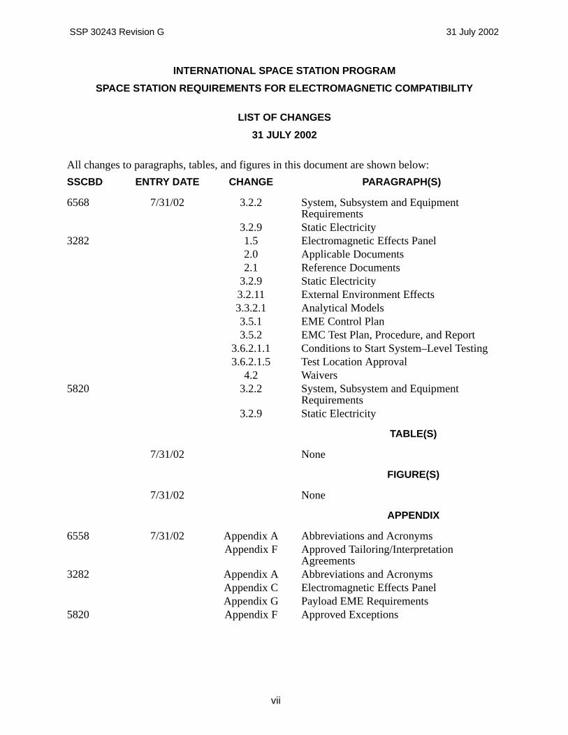
All changes to paragraphs, tables, and figures in this document are shown below:
SSCBD ENTRY DATE CHANGE PARAGRAPH(S)
6568 7/31/02 3.2.2 System, Subsystem and EquipmentRequirements
3.2.9 Static Electricity3282 1.5 Electromagnetic Effects Panel
2.0 Applicable Documents2.1 Reference Documents
3.2.9 Static Electricity3.2.11 External Environment Effects3.3.2.1 Analytical Models3.5.1 EME Control Plan3.5.2 EMC Test Plan, Procedure, and Report
3.6.2.1.1 Conditions to Start System–Level Testing3.6.2.1.5 Test Location Approval
4.2 Waivers5820 3.2.2 System, Subsystem and Equipment
Requirements3.2.9 Static Electricity
TABLE(S)
7/31/02 None
FIGURE(S)
7/31/02 None
APPENDIX
6558 7/31/02 Appendix A Abbreviations and AcronymsAppendix F Approved Tailoring/Interpretation
Agreements3282 Appendix A Abbreviations and Acronyms
Appendix C Electromagnetic Effects PanelAppendix G Payload EME Requirements
5820 Appendix F Approved Exceptions
SSP 30243 Revision G 31 July 2002
viii
TABLE OF CONTENTS
PARAGRAPH PAGE
1.0 GENERAL 1 – 1. . . . . . . . . . . . . . . . . . . . . . . . . . . . . . . . . . . . . . . . . . . . . . . . . . . . . . . . . . . 1.1 INTRODUCTION 1 – 1. . . . . . . . . . . . . . . . . . . . . . . . . . . . . . . . . . . . . . . . . . . . . . . . . . . . . . 1.1.1 PRIME CONTRACTOR RESPONSIBILITIES 1 – 1. . . . . . . . . . . . . . . . . . . . . . . . . . . . . 1.1.2 HARDWARE PROVIDER RESPONSIBILITIES 1 – 1. . . . . . . . . . . . . . . . . . . . . . . . . . . 1.2 PURPOSE 1 – 1. . . . . . . . . . . . . . . . . . . . . . . . . . . . . . . . . . . . . . . . . . . . . . . . . . . . . . . . . . . 1.3 SCOPE 1 – 2. . . . . . . . . . . . . . . . . . . . . . . . . . . . . . . . . . . . . . . . . . . . . . . . . . . . . . . . . . . . . . 1.4 INTENDED USE 1 – 2. . . . . . . . . . . . . . . . . . . . . . . . . . . . . . . . . . . . . . . . . . . . . . . . . . . . . . 1.5 ELECTROMAGNETIC EFFECTS PANEL 1 – 2. . . . . . . . . . . . . . . . . . . . . . . . . . . . . . . . 1.6 PRECEDENCE 1 – 2. . . . . . . . . . . . . . . . . . . . . . . . . . . . . . . . . . . . . . . . . . . . . . . . . . . . . . . 2.0 APPLICABLE DOCUMENTS 2 – 1. . . . . . . . . . . . . . . . . . . . . . . . . . . . . . . . . . . . . . . . . . . 2.1 REFERENCE DOCUMENTS 2 – 2. . . . . . . . . . . . . . . . . . . . . . . . . . . . . . . . . . . . . . . . . . . 3.0 REQUIREMENTS 3 – 1. . . . . . . . . . . . . . . . . . . . . . . . . . . . . . . . . . . . . . . . . . . . . . . . . . . . . 3.1 DEFINITION OF ELECTROMAGNETIC COMPATIBILITY
REQUIREMENTS 3 – 1. . . . . . . . . . . . . . . . . . . . . . . . . . . . . . . . . . . . . . . . . . . . . . . . . . . . . 3.2 CHARACTERISTICS 3 – 1. . . . . . . . . . . . . . . . . . . . . . . . . . . . . . . . . . . . . . . . . . . . . . . . . . 3.2.1 SYSTEM AND SUBSYSTEM COMPATIBILITY 3 – 1. . . . . . . . . . . . . . . . . . . . . . . . . . . . 3.2.2 SYSTEM, SUBSYSTEM, AND EQUIPMENT REQUIREMENTS 3 – 2. . . . . . . . . . . . . 3.2.3 ELECTROMAGNETIC INTERFERENCE SAFETY MARGINS FOR
CRITICAL CIRCUITS 3 – 2. . . . . . . . . . . . . . . . . . . . . . . . . . . . . . . . . . . . . . . . . . . . . . . . . . 3.2.3.1 INTERFERENCE AND SUSCEPTIBILITY CONTROL 3 – 2. . . . . . . . . . . . . . . . . . . . . . 3.2.4 DEGRADATION CRITERIA 3 – 2. . . . . . . . . . . . . . . . . . . . . . . . . . . . . . . . . . . . . . . . . . . . . 3.2.5 WIRING AND CABLING DESIGN 3 – 3. . . . . . . . . . . . . . . . . . . . . . . . . . . . . . . . . . . . . . . 3.2.6 ELECTRICAL POWER AND ELECTRICAL INTERFACE 3 – 3. . . . . . . . . . . . . . . . . . . 3.2.7 BONDING AND GROUNDING 3 – 3. . . . . . . . . . . . . . . . . . . . . . . . . . . . . . . . . . . . . . . . . . 3.2.8 LAUNCH ELEMENT TRANSPORTATION, STORAGE, AND LAUNCH
ENVIRONMENT 3 – 3. . . . . . . . . . . . . . . . . . . . . . . . . . . . . . . . . . . . . . . . . . . . . . . . . . . . . . 3.2.8.1 LAUNCH 3 – 3. . . . . . . . . . . . . . . . . . . . . . . . . . . . . . . . . . . . . . . . . . . . . . . . . . . . . . . . . . . . . 3.2.8.2 TRANSPORTATION AND STORAGE 3 – 3. . . . . . . . . . . . . . . . . . . . . . . . . . . . . . . . . . . . 3.2.8.3 TRANSITION PHASE 3 – 4. . . . . . . . . . . . . . . . . . . . . . . . . . . . . . . . . . . . . . . . . . . . . . . . . . 3.2.9 STATIC ELECTRICITY 3 – 4. . . . . . . . . . . . . . . . . . . . . . . . . . . . . . . . . . . . . . . . . . . . . . . . . 3.2.10 ELECTROEXPLOSIVE DEVICES 3 – 4. . . . . . . . . . . . . . . . . . . . . . . . . . . . . . . . . . . . . . . 3.2.11 EXTERNAL ENVIRONMENT EFFECTS 3 – 4. . . . . . . . . . . . . . . . . . . . . . . . . . . . . . . . . 3.2.12 MATERIALS AND PROCESSES 3 – 4. . . . . . . . . . . . . . . . . . . . . . . . . . . . . . . . . . . . . . . . 3.2.13 CORONA 3 – 5. . . . . . . . . . . . . . . . . . . . . . . . . . . . . . . . . . . . . . . . . . . . . . . . . . . . . . . . . . . . 3.3 ANALYSIS 3 – 5. . . . . . . . . . . . . . . . . . . . . . . . . . . . . . . . . . . . . . . . . . . . . . . . . . . . . . . . . . . 3.3.1 ANALYSIS REQUIREMENTS 3 – 5. . . . . . . . . . . . . . . . . . . . . . . . . . . . . . . . . . . . . . . . . . . 3.3.2 ANALYTICAL MODELS AND METHODS 3 – 5. . . . . . . . . . . . . . . . . . . . . . . . . . . . . . . . . 3.3.2.1 ANALYTICAL MODELS 3 – 5. . . . . . . . . . . . . . . . . . . . . . . . . . . . . . . . . . . . . . . . . . . . . . . . 3.4 GFE AND COMMERCIAL OFF–THE–SHELF EQUIPMENT 3 – 5. . . . . . . . . . . . . . . . 3.4.1 SELECTION AND USE OF EQUIPMENT 3 – 5. . . . . . . . . . . . . . . . . . . . . . . . . . . . . . . . 3.4.1.1 COMMERCIAL OFF–THE–SHELF EQUIPMENT 3 – 5. . . . . . . . . . . . . . . . . . . . . . . . . . 3.4.1.2 GOVERNMENT FURNISHED EQUIPMENT 3 – 6. . . . . . . . . . . . . . . . . . . . . . . . . . . . . . 3.5 DOCUMENTATION 3 – 6. . . . . . . . . . . . . . . . . . . . . . . . . . . . . . . . . . . . . . . . . . . . . . . . . . . . 3.5.1 EME CONTROL PLAN 3 – 6. . . . . . . . . . . . . . . . . . . . . . . . . . . . . . . . . . . . . . . . . . . . . . . . . 3.5.2 EMC TEST PLAN, PROCEDURE, AND REPORT 3 – 7. . . . . . . . . . . . . . . . . . . . . . . . . 3.5.3 EME DESIGN ANALYSIS REPORT 3 – 7. . . . . . . . . . . . . . . . . . . . . . . . . . . . . . . . . . . . . 3.5.4 EMI TEST PLANS, PROCEDURES, AND REPORTS 3 – 7. . . . . . . . . . . . . . . . . . . . . . 3.6 VERIFICATION 3 – 7. . . . . . . . . . . . . . . . . . . . . . . . . . . . . . . . . . . . . . . . . . . . . . . . . . . . . . .
SSP 30243 Revision G 31 July 2002
ix
TABLE OF CONTENTS – Continued
PARAGRAPH PAGE
3.6.1 VERIFICATION METHODS 3 – 7. . . . . . . . . . . . . . . . . . . . . . . . . . . . . . . . . . . . . . . . . . . . . 3.6.2 INTEGRATION TESTS 3 – 7. . . . . . . . . . . . . . . . . . . . . . . . . . . . . . . . . . . . . . . . . . . . . . . . 3.6.2.1 DELIVERABLE END ITEM COMPATIBILITY TEST 3 – 7. . . . . . . . . . . . . . . . . . . . . . . . 3.6.2.1.1 CONDITIONS TO START SYSTEM–LEVEL TESTING 3 – 8. . . . . . . . . . . . . . . . . . . . . 3.6.2.1.2 COMPLIANCE 3 – 8. . . . . . . . . . . . . . . . . . . . . . . . . . . . . . . . . . . . . . . . . . . . . . . . . . . . . . . . 3.6.2.1.3 TEST PLAN 3 – 8. . . . . . . . . . . . . . . . . . . . . . . . . . . . . . . . . . . . . . . . . . . . . . . . . . . . . . . . . . 3.6.2.1.4 POWER QUALITY 3 – 8. . . . . . . . . . . . . . . . . . . . . . . . . . . . . . . . . . . . . . . . . . . . . . . . . . . . 3.6.2.1.5 TEST LOCATION APPROVAL 3 – 8. . . . . . . . . . . . . . . . . . . . . . . . . . . . . . . . . . . . . . . . . . 3.6.2.1.6 TEST ITEM OPERATING ADJUSTMENTS 3 – 8. . . . . . . . . . . . . . . . . . . . . . . . . . . . . . . 3.6.2.1.7 COMPATIBILITY 3 – 9. . . . . . . . . . . . . . . . . . . . . . . . . . . . . . . . . . . . . . . . . . . . . . . . . . . . . . 3.6.2.1.8 INSTRUMENTATION 3 – 9. . . . . . . . . . . . . . . . . . . . . . . . . . . . . . . . . . . . . . . . . . . . . . . . . . 3.6.2.1.8.1 INSTRUMENTATION MEASUREMENT STANDARDS 3 – 9. . . . . . . . . . . . . . . . . . . . . 3.6.2.1.9 OPERATING MODES 3 – 9. . . . . . . . . . . . . . . . . . . . . . . . . . . . . . . . . . . . . . . . . . . . . . . . . 3.6.2.1.10 SIMULATED INTERFACES 3 – 9. . . . . . . . . . . . . . . . . . . . . . . . . . . . . . . . . . . . . . . . . . . . . 3.6.2.1.11 GENERAL CONDITIONS 3 – 9. . . . . . . . . . . . . . . . . . . . . . . . . . . . . . . . . . . . . . . . . . . . . . 3.6.2.1.12 ACCEPTANCE CRITERIA 3 – 10. . . . . . . . . . . . . . . . . . . . . . . . . . . . . . . . . . . . . . . . . . . . . . 3.6.2.1.13 TEST SITE AMBIENT ELECTROMAGNETIC ENVIRONMENT 3 – 10. . . . . . . . . . . . . 3.6.3 TEST ANALYSIS 3 – 10. . . . . . . . . . . . . . . . . . . . . . . . . . . . . . . . . . . . . . . . . . . . . . . . . . . . . . 4.0 QUALITY ASSURANCE PROVISIONS 4 – 1. . . . . . . . . . . . . . . . . . . . . . . . . . . . . . . . . . 4.1 RESPONSIBILITY FOR INSPECTION 4 – 1. . . . . . . . . . . . . . . . . . . . . . . . . . . . . . . . . . . 4.2 WAIVERS 4 – 1. . . . . . . . . . . . . . . . . . . . . . . . . . . . . . . . . . . . . . . . . . . . . . . . . . . . . . . . . . . .
APPENDIX PAGE
A ABBREVIATIONS AND ACRONYMS A – 1. . . . . . . . . . . . . . . . . . . . . . . . . . . . . . . . . . . . B GLOSSARY B – 1. . . . . . . . . . . . . . . . . . . . . . . . . . . . . . . . . . . . . . . . . . . . . . . . . . . . . . . . . . C ELECTROMAGNETIC EFFECTS PANEL C – 1. . . . . . . . . . . . . . . . . . . . . . . . . . . . . . . . D EME CONFIGURATION, ANALYSIS, AND TEST DATABASE D – 1. . . . . . . . . . . . . . . E MODIFICATIONS TO MIL–STD–1576 E – 1. . . . . . . . . . . . . . . . . . . . . . . . . . . . . . . . . . . F APPROVED TAILORING/INTERPRETATION AGREEMENTS F – 1. . . . . . . . . . . . . . G PAYLOAD EME REQUIREMENTS G – 1. . . . . . . . . . . . . . . . . . . . . . . . . . . . . . . . . . . . . .
SSP 30243 Revision G 31 July 2002
1 – 1
1.0 GENERAL
The International Space Station (ISS) system requirement for Electromagnetic Effects Control(EMEC) shall be achieved by design within all segments, subsystems, and equipment within theISS, by interface design with the National Space Transportation System (NSTS), and by designwith the external electromagnetic environment.
1.1 INTRODUCTION
This requirements document establishes the Electromagnetic Effects (EME) process design andverification requirements for the ISS. The requirements of this document are applicable tohardware providers (HWP) including Space Station Flight Segments (SSFS), Ground SystemSegment (GSS), Government Furnished Equipment (GFE), Ground Support Equipment (GSE),Flight Support Equipment, Orbital Support Equipment (OSE), Payloads, and CommercialOff–the–Shelf equipment (COTS).
1.1.1 PRIME CONTRACTOR RESPONSIBILITIES
The Prime Contractor shall establish an overall integrated EME process for the ISS. The overallprocess shall include the necessary design, planning, technical criteria, and management controlsneeded to achieve overall EMEC and to ensure that the design and verification requirementsspecified herein are met. The ISS EME process shall be based on the requirements of SSP30243 and the prime Statement of Work. The Prime Contractor shall direct each HWP toestablish the technical effort and management controls necessary to accomplish their individualparts of the overall EMEC process.
1.1.2 HARDWARE PROVIDER RESPONSIBILITIES
HWPs shall have the responsibility for compliance with all requirements subsequent to 1.1.1 inaccordance with the Prime Contractor’s responsibilities of 1.1.1. The Prime Contractor shall beadvised when compliance with these requirements compromises operational capabilities or whencompliance will not ensure Electromagnetic Compatibility (EMC). The Prime Contractor shallbe notified a minimum of 10 working days before any test start and shall have the option towitness the test.
1.2 PURPOSE
The purpose of this requirements document is to define a common electromagnetic design,control, test, and verification process for the ISS.
SSP 30243 Revision G 31 July 2002
1 – 2
1.3 SCOPE
This document defines the ISS requirements for electromagnetic effects control including theresponsibilities of all program participants for implementation, analysis, test, and verification.
1.4 INTENDED USE
This document is intended for use by the ISS. It is a requirement for the HWPs and, asdetermined, the International Partners (IP), including, in whole or part, their subcontractors.
1.5 ELECTROMAGNETIC EFFECTS PANEL
An Electromagnetic Effects Panel (EMEP) has been chartered by the Test and VerificationControl Panel (T&VCP) as the management forum that oversees and reviews the program wideelectromagnetic compatibility program, provides a resource for technical consultation andrequirements interpretation, and provides a forum for resolving EME issues. The panel serves asthe technical forum for maintenance of EME requirements and evaluation of reports and plans.This panel ensures HWPs establish uniform application of program EME requirements. TheEMEP provides a means for expediting the solutions of technical problems and establishingchannels for coordination. The details of operation for the EMEP are included in the EMEPcharter, discussed in Appendix C of this document. The team is chaired by the NASA EME leadand cochaired by the Boeing EME lead. Members of the Team include representatives fromSpace Shuttle Program; Boeing, Houston; Space Station Hardware Integration Office, KSC;Operations Office, ISSP; Payloads Office, ISSP; Engineering Directorate, JSC; Safety andMission Assurance/Program Risk Office, ISSP; Independent Assessment Office, ISSP; andNASA Frequency Management Office. Ad hoc members include the affected subsystem ortechnical discipline area requirement owner, NASA ISSP; the affected subsystem or technicaldiscipline area requirement owner, Boeing ISSP; Affected Manager, ISSP Element; AffectedLaunch Package Manager; Mission Operations Directorate, JSC; and International PartnersRepresentative(s).
1.6 PRECEDENCE
In the event of conflict between this document and any other Electromagnetic Interference (EMI)requirements document (e.g., SSP 30237, SSP 30238, SSP 30240, SSP 30242, and SSP 30245),this document shall take precedence.
In the event of conflict, the requirements of this document supersede those requirements inMIL–STD–1576 Basic Revision, July 31, 1984, and Notice 01, September 4, 1992, as applied tothe ISS. The intent is to provide ISS specific clarification of the requirements ofMIL–STD–1576 rather than replacement of those requirements.
SSP 30243 Revision G 31 July 2002
2 – 1
2.0 APPLICABLE DOCUMENTS
The following applicable documents of the exact issue shown in the current issue of SSP 50257form a part of this specification to the extent specified herein. Inclusion of applicable documentsherein does not in any way supersede the order of precedence identified in paragraph 1.6. Thereferences show where each applicable document is cited in this document.
DOCUMENT NO. TITLE
NSTS–21000–IDD–ISS International Space Station Interface Definition DocumentParagraphs: 3.2.8.1, 3.2.8.2, 3.2.8.3
KSC–STA–61.01 Space Station Processing Facility (SSPF) Facility andEquipment Design Plan (FEDP)
Paragraph: 3.2.8.2
MIL–B–5087 Bonding, Electrical, and Lightning Protection, for AerospaceSystems
Paragraph: 3.2.2
MIL–STD–461 Electromagnetic Emission and Susceptibility Requirements forthe Control of Electromagnetic Interference
Paragraph: 3.2.2
MIL–STD–1576 Electroexplosive Subsystem Safety Requirements and TestMethods for Space Systems
Paragraph: 3.2.10
MIL–STD–1686 Electrostatic Discharge Control Program for Protection ofElectrical And Electronic Parts, Assemblies and Equipment(Excluding Electrically Initiated Explosive Devices)
Paragraph: 3.2.9
SSP 30233 Space Station Requirements for Materials and ProcessesParagraph: 3.2.12
SSP 30237 Space Station Electromagnetic Emission and SusceptibilityRequirements
Paragraphs: 1.6, 3.2.2, 3.2.11, 3.6.2.1.2
SSP 30238 Space Station Electromagnetic TechniquesParagraphs: 3.2.2, 3.6.2.1.2
SSP 30240 Space Station Grounding RequirementsParagraphs: 3.2.2, 3.2.7, 3.2.10, 3.6.2.1.2
SSP 30243 Revision G 31 July 2002
2 – 2
DOCUMENT NO. TITLE
SSP 30242 Space Station Cable/Wire Design and Control Requirementsfor Electromagnetic Compatibility
Paragraphs: 3.2.2, 3.2.5, 3.2.10, 3.6.2.1.2
SSP 30245 Space Station Electrical Bonding RequirementsParagraphs: 3.2.2, 3.2.7, 3.2.10, 3.2.12, 3.6.2.1.2
SSP 30482, Volume 1 Electrical Power Specifications and Standards Volume 1: EPSElectrical Performance Specifications
Paragraphs: 3.2.6, 3.6.2.1.4
SSP 30482, Volume 2 Electrical Power Specifications and Standards Volume 2:Consumer Constraints
Paragraphs: 3.2.6, 3.6.2.1.4
2.1 REFERENCE DOCUMENTS
The following documents are referenced in this specification as a guide for context and userconvenience. The references to these documents may not be listed in SSP 50257.
DOCUMENT NO. TITLE
D684–10263–01 Electromagnetic Effects Verification Plan
MSFC–STD–531 High Voltage Design Criteria
SSP 30243 Revision G 31 July 2002
3 – 1
3.0 REQUIREMENTS
3.1 DEFINITION OF ELECTROMAGNETIC COMPATIBILITY REQUIREMENTS
The system and all associated subsystem equipment, both on–orbit and ground, shall be designedto achieve electromagnetic compatibility. The HWP specification and interface documents shallcontain supplementary requirements as necessary to achieve electromagnetic compatibility. As aminimum, the Tier I Contractors, Payload Providers, and IPs EME control process shall coverthe following areas:
— Bonding and grounding
— Corona
— Degradation criteria
— Electrical power and electrical interface
— EMI safety margins for critical equipment
— EME analysis requirements and methodologies
— External environment effects
— Interactions with other technologies including, but not limited to, functionality,maintainability, plasma, reliability, materials and processes, and safety
— Interference and susceptibility control
— Launch element transportation, storage, handling, and launch environments
— Lightning protection
— Material and processes
— Personnel hazards
— Pyrotechnics and Bridge Wire Actuated Devices
— Spacecraft charging controls
— Static electricity
— Subsystem compatibility
— Subsystems and equipment requirements
— Wiring and cable
3.2 CHARACTERISTICS
3.2.1 SYSTEM AND SUBSYSTEM COMPATIBILITY
Compatibility shall be demonstrated between system and subsystems by functionality with therequired safety margin. The GSS, along with training devices and simulators, shall be designedfor compatibility.
SSP 30243 Revision G 31 July 2002
3 – 2
3.2.2 SYSTEM, SUBSYSTEM, AND EQUIPMENT REQUIREMENTS
The ISS system, segments, subsystems, and equipment shall be designed to meet therequirements of this document. Electrical and electronic equipment, as mounted and enclosured(including racks, nonconductive mounting, cold plate mounting, portable enclosures, etc.), shallmeet the requirements of SSP 30237 when tested in accordance with SSP 30238. Electricalgrounding shall meet the requirements of SSP 30240. Electrical bonding shall meet therequirements of SSP 30245. Electrical cable design shall meet the requirements of SSP 30242.GSE for Product Group (PG) only shall meet the requirements of MIL–STD–461 andMIL–B–5087. Approved EME waivers shall be included in the HWPs EME Design AnalysisReport. See appendix F for exceptions (EMECB Tailoring Interpretation Agreement(TIA)–0060, EMECB TIA–0061, EMECB TIA–0092, EMECB TIA–0195, EMECB TIA–0196,EMEP TIA–0233, EMEP TIA–0384, EMEP TIA–0419, and EMEP TIA–0420) to thisparagraph.
3.2.3 ELECTORMAGNETIC INTERFERENCE SAFETY MARGINS FOR CRITICALCIRCUITS
Circuits implementing critical functions such that incorrect operations due to EMI could result inloss of life or loss of ISS shall be demonstrated to have an EMI safety margin of 6 dB by test or20 dB by analysis. For analyses in which the EMI safety margin is in part established bymeasured emission or susceptibility characteristics, margins of 10 dB shall be demonstrated.EMI safety margins for firing circuits of critical electroexplosive devices (see 3.2.10 forexploding bridgewire type devices) shall be demonstrated to be 20 dB by test or 34 dB byanalysis. See appendix F for exception (EMECB TIA–0091) to this paragraph.
3.2.3.1 INTERFERENCE AND SUSCEPTIBILITY CONTROL
The ISS subsystems and equipment shall function with the required margins identified in 3.2.3when subjected to EMI produced by any of the subsystems or equipment associated with thesystem. This shall be accomplished through design. Verification shall be by analysis and tests asspecified in this document.
3.2.4 DEGRADATION CRITERIA
Degradation criteria shall be established by the HWP for each system, subsystem, andequipment. These criteria shall be used to define and evaluate malfunctions, unacceptable, andundesirable responses.
SSP 30243 Revision G 31 July 2002
3 – 3
3.2.5 WIRING AND CABLING DESIGN
Wiring and cabling shall be designed in accordance with SSP 30242. Wiring and cabling shallbe selected, classified, and bundled in accordance with the requirements and procedures in SSP30242. Cables, wires, and cable and wire bundles shall be located and routed to provide a 20 dBcable to cable coupling loss using physical or electrical separation and considering the worst casesteady state or transient conditions. Cable design shall include provisions for termination ofshielded wires in accordance with SSP 30242. Connectors used to carry wires with overallshields shall use a conductive finish and shall use a back shell that provides for peripheralbonding of shields. Wire or cable shall be categorized according to interference andsusceptibility characteristics in accordance with the requirements of SSP 30242. Wires andcables shall be marked in such a manner that personnel can visually identify the EMC categoryfor each wire or cable. The end to end path of each and every wire and cable conductor shall bedocumented and the cable bundle, physical path, and wire code (color, marking, classification,size, type, etc.) shall be identified to support EME design analysis as well as maintenance andgrowth.
3.2.6 ELECTRICAL POWER AND ELECTRICAL INTERFACE
The ISS system, subsystems, and equipment shall not malfunction, or have unacceptableresponses due to surges, ripples, voltages, and other electrical conditions that can causeinterference or susceptibility, when supplied with electrical power conforming to SSP 30482.
3.2.7 BONDING AND GROUNDING
Bonding and grounding provisions shall be in accordance with SSP 30240 and SSP 30245.
3.2.8 LAUNCH ELEMENT TRANSPORTATION, STORAGE, AND LAUNCH ENVIRONMENT
3.2.8.1 LAUNCH
The ISS launch element shall be designed such that inadvertent action or failure will not occurwhen subject to the payload bay lightning induced environment resulting from a lightning striketo the NSTS as defined in NSTS–21000–IDD–ISS.
3.2.8.2 TRANSPORTATION AND STORAGE
The HWP electromagnetic environment during transportation and storage of the launch elementshall be controlled in accordance with KSC–STA–61.01 and shall not exceed the launchenvironment defined in NSTS–21000–IDD–ISS.
SSP 30243 Revision G 31 July 2002
3 – 4
3.2.8.3 TRANSITION PHASE
The ISS launch element during transition to orbit shall not exceed or be susceptible toelectromagnetic environments defined in NSTS–21000–IDD–ISS.
3.2.9 STATIC ELECTRICITY
Unpowered electronic equipment and components shall not be damaged by ElectrostaticDischarges (ESD) equal to or less than 4000 volts to the case or to any pin on externalconnectors. Equipment that may be damaged by ESD between 4000 and 15000 volts must havea label affixed to the case in a location clearly visible in the installed position. Handling ofequipment susceptible to ESD up to 15000 volts shall be in accordance with MIL–STD–1686.These voltages are the results of charges that may be accumulated and discharged from groundpersonnel or crew members during equipment installation or removal. When testing or analysisfor ESD susceptibility is performed, the ESD hazard from personnel shall be simulated bycharging a 100 picofarad capacitance and discharging it through a 1500 ohm resistor. Seeappendix F for the exceptions (EMECB TIA–0042, EMEP TIA–0230, EMEP TIA–0248, EMEPTIA–0274, EMEP TIA–0289, EMEP TIA–0290, EMEP TIA–0302, EMEP TIA–0367, EMEPTIA–0369, EMEP TIA–379, and EMEP TIA–0422) to this paragraph.
3.2.10 ELECTROEXPLOSIVE DEVICES
The system design shall conform to the requirements of MIL–STD–1576 as modified byappendix E and shall include provisions to protect Electroexplosive Devices (EED) frominadvertent ignition or dudding caused by any form of electromagnetic or electrostatic energy.All wiring, cabling, and hardware associated with the EEDs shall be designed to prevent straypickup and eliminate undesired energy. Safety margin requirements for EEDs are defined in3.2.3. Grounding and bonding requirements for EEDs shall meet the requirements of SSP 30240and SSP 30245. Wiring requirements for EEDs are defined in SSP 30242.
3.2.11 EXTERNAL ENVIRONMENT EFFECTS
System, subsystem, equipment, and component designs shall analyze and document potentialfailures caused by external electromagnetic environments. The external electromagneticenvironments are defined in SSP 30237 or D684–10263–01.
3.2.12 MATERIALS AND PROCESSES
Materials and processes shall conform to the electrical and electronic requirements of SSP 30233and as supplemented in SSP 30245.
SSP 30243 Revision G 31 July 2002
3 – 5
3.2.13 CORONA
Electrical and electronic subsystems, equipment, and systems shall be designed to precludedamaging or destructive corona in any ISS operating environment. An analysis shall beprovided to verify the corona shall not create damaging or destructive effects. See appendix Ffor the exceptions (EMEP TIA–0274, EMEP TIA–0291, EMEP TIA–0304, and EMEPTIA–0316) to this paragraph.
3.3 ANALYSIS
3.3.1 ANALYSIS REQUIREMENTS
Subsystems shall be analyzed for EME to support:
— Quantitative evaluation of proposed designs and design changes.
— Specification tailoring and waiver evaluation.
— Test result assessments.
— Verification test planning and critical test point selection.
— Quantitative assessment of the ISS function safety margins for configuration changes.
3.3.2 ANALYTICAL MODELS AND METHODS
3.3.2.1 ANALYTICAL MODELS
Analytical models used to perform and support analyses provided in the Design Analysis Report(DAR) shall be described in sufficient detail in the DAR to support technical evaluation by theEMEP. Use of model software tools such as IEMCAP, SEMCAP, and ISEAS which provideintegrated system analyses, shall be permitted along with analyses performed with generalpurpose problem solving tools, such as MATHEMATICA, MATLAB, MATHCAD andspreadsheets. Appendix D is the methodology used by the EMEP to perform integration analysisof the Space Station.
3.4 GFE AND COMMERCIAL OFF–THE–SHELF EQUIPMENT
3.4.1 SELECTION AND USE OF EQUIPMENT
3.4.1.1 COMMERCIAL OFF–THE–SHELF EQUIPMENT
When COTS equipment is considered for use, the following rules shall be used in selecting andutilizing the equipment in the system:
SSP 30243 Revision G 31 July 2002
3 – 6
— The equipment shall be considered adequate if emission and susceptibility test data areavailable to demonstrate compatibility.
— When compliance with interference requirements cannot be substantiated due tounavailability of test reports, then laboratory interference tests shall be performed forqualification of the subsystem as negotiated with the responsible authority for the equipment.
— If it is determined that more stringent requirements are necessary after evaluation ofavailable data, it shall be the responsibility of the procuring authority to direct the supplier toimplement these requirements or to select another equipment with adequate characteristics.
3.4.1.2 GOVERNMENT FURNISHED EQUIPMENT
GFE that is required for use in the system shall be acceptable from an EME viewpoint, providedthe interference and susceptibility requirements as outlined below are met:
— As a minimum, subsystem and equipment designs must have met the EMI safety marginrequirements of this document and be supported by approved qualification test reports.
— When compliance with applicable specifications cannot be substantiated, laboratory testsshall be performed for qualification of systems, subsystems, or equipment to the applicablerequirements as negotiated with the responsible flight element, system, or subsystemauthority.
— GFE which cannot meet the requirements and for which external suppression measures areineffective shall be modified if approved by the responsible flight element, system,subsystem, or equipment procuring authority. If such procedures are not specified, the flightelement, system, subsystem, or equipment supplier shall advise the responsible authority by atimely letter of systems, subsystems, or equipment that cannot meet the requirements and ofpertinent details concerning the modifications required.
— When GFE is demonstrated to cause interference that cannot be eliminated by properinstallation, control of the system electromagnetic environment, or by reasonablemodification to the flight element, system, subsystem, or equipment, then NASA shall havethe authority to waive the requirement.
3.5 DOCUMENTATION
3.5.1 EME CONTROL PLAN
Each Tier I Contractor, Payload Provider, and IP shall submit an EME Control Plan to theEMEP. The EME Control Plan shall include details describing element, system, subsystem, andequipment control processes. Verification planning including tests and analysis shall besummarized in the EME Control Plan.
SSP 30243 Revision G 31 July 2002
3 – 7
3.5.2 EMC TEST PLAN, PROCEDURE, AND REPORT
Each Tier I Contractor, Payload Provider, and IP, shall submit an EMC Test Plan, Procedure, andReport to the EMEP. The EMC Test Plan shall include details as defined in the InternationalTechnical Agreements and PG Supplier Data Requirements Lists.
3.5.3 EME DESIGN ANALYSIS REPORT
Each Tier I Contractor, Payload Provider, and IP shall submit an EME DAR. The EME DARshall include details and conditions for the element, system, subsystem, and equipment includedin the deliverable end item. In addition to the DAR, each HWP shall provide configuration data,analysis data, and test results data to the Prime Contractor in the detail and format as defined forthe EME Configuration, Analysis, and Test Data Base (appendix D). For International Partnersthe detail and format of these data exchanges are defined in the Bilateral Data ExchangeAgreements.
3.5.4 EMI TEST PLANS, PROCEDURES, AND REPORTS
HWPs shall provide EMI test plans, procedures, and reports.
3.6 VERIFICATION
3.6.1 VERIFICATION METHODS
Flight element, systems, subsystems, and equipment compatibility shall be verified by acombination of tests, demonstrations, analyses, and inspections.
3.6.2 INTEGRATION TESTS
3.6.2.1 DELIVERABLE END ITEM COMPATIBILITY TEST
Tier I Contractors, Payload Providers, and IPs shall perform a system EMC test on the highestlevel deliverable end item package. The test shall include:
— A functional compatibility demonstration to verify that the deliverable end item equipment isselfcompatible.
— An interface test with simulated sources and loads to show that circuits interfacing with thenext highest level of assembly function compatibly with the interface (including groundingand bonding).
— Safety margin tests where margins have not been previously determined by equipment leveltests or analyses.
SSP 30243 Revision G 31 July 2002
3 – 8
3.6.2.1.1 CONDITIONS TO START SYSTEM–LEVEL TESTING
Outstanding approved engineering orders, engineering change proposals, modifications, andconfiguration changes applicable to the end item components shall have been incorporated andinstalled prior to test. Requests for exceptions shall contain supporting rationale for tests ofsubstandard configurations and shall be submitted to the EMEP for approval.
3.6.2.1.2 COMPLIANCE
Equipment components of the end item shall be complied with applicable equipment level EMIand EMC specifications (SSP 30237, SSP 30238, SSP 30240, SSP 30242, and SSP 30245) orhave approved waivers allowing the specification exceptions.
3.6.2.1.3 TEST PLAN
Tests shall not be conducted without an approved test plan.
3.6.2.1.4 POWER QUALITY
External electrical power supplied to the flight element, system, or subsystem, under test shallsimulate the power quality requirements and interface (including dynamic impedance)requirements of SSP 30482. The end item compatibility test will be performed with its inputpower set to the worst case input voltage levels (i.e, the high limit, nominal level, or low limit)called out in SSP 30482.
3.6.2.1.5 TEST LOCATION APPROVAL
Tests shall not be conducted where the electromagnetic environment at the test site would affectthe validity of the tests. The location and environment of the test site shall be included in the testplan and submitted for approval to the EMEP.
3.6.2.1.6 TEST ITEM OPERATING ADJUSTMENTS
During tests, all electronic flight elements, systems, subsystems, and equipment under control ofcrew or ground operations personnel shall be adjusted within the limits of the test articlespecification(s) for nominal operating conditions (i.e., a receiver squelch circuit shall be set to itsnormal operating position and not to extreme positions) to provide indication of interference orsusceptibility consistent with planned operation.
SSP 30243 Revision G 31 July 2002
3 – 9
3.6.2.1.7 COMPATIBILITY
Tests shall be performed to indicate compatible operation, undesirable responses, unacceptableresponses, or malfunctions while all flight elements, systems, subsystems, and equipment areoperated. It shall be the responsibility of the supplier to determine conclusively and correctly thecauses of noncompatibility (i.e., the source(s), coupling paths, and susceptible components) inorder to support hardware and software fixes, operational workarounds, or preparation of waiverrequests.
3.6.2.1.8 INSTRUMENTATION
Each EME test shall be monitored by appropriate means to assure adequate recording ofmeasured data used to evaluate the effects of test article operation and demonstrate the requiredsafety margins. Instrumentation used shall be specified in the test plan.
3.6.2.1.8.1 INSTRUMENTATION MEASUREMENT STANDARDS
Instrumentation shall meet or exceed measurement standards traceable to standards maintainedby the National Institute of Standards and Technology or other value(s) derived from a controlledmeasurement process utilizing a fundamental constant of nature.
3.6.2.1.9 OPERATING MODES
The overall system shall be operated in representative modes of operation as defined in the testplan. Representative modes including programmed missions, flight, and stage assembly shall beused. Known worst case modes as determined by analysis shall be included in the test plan.
3.6.2.1.10 SIMULATED INTERFACES
When test articles require simulation of interfaces with equipment not the responsibility of thesupplier, or where special inputs are required, the means of simulating these interfaces shall bedescribed in the test plan.
3.6.2.1.11 GENERAL CONDITIONS
The EMC tests shall demonstrate required compatibility when flight elements, systems,subsystems, equipment, including GSE, and simulators are individually or collectively operatedin representative modes of operation. Transmitters and receivers shall be operated at thosecritical frequencies identified during system analysis and laboratory tests. Multichanneltransmitters and receivers shall be tested at a representative number of frequencies usually notless than 20. If the system uses special frequencies for command channels, distress messages, orother purposes, the frequencies shall be given special attention.
SSP 30243 Revision G 31 July 2002
3 – 10
3.6.2.1.12 ACCEPTANCE CRITERIA
Compliance with this requirements document shall be achieved when compatible operation ofthe test item is demonstrated along with the existence of the required safety margins atdesignated critical circuits.
3.6.2.1.13 TEST SITE AMBIENT ELECTROMAGNETIC ENVIRONMENT
The electromagnetic ambient environment at the end item test site shall be measured, recorded,and analyzed to ensure that the ambient environment does not degrade test results or maskinterference from the test article. The environment shall be monitored periodically during thetest and shall be controlled to the extent necessary to prevent test degradation (i.e., by shuttingoff local external sources or conducting the test during times when the local external sources arenot present). Ambient signals (both steady state and transient) shall be considered as a possiblesource of interference and will be measured when end item functions cannot be positivelyidentified as interference sources.
3.6.3 TEST ANALYSIS
Test analyses shall be performed as necessary to utilize the end item, equipment, subsystem, andequipment test data in support of verification of the EMC requirements.
SSP 30243 Revision G 31 July 2002
4 – 1
4.0 QUALITY ASSURANCE PROVISIONS
4.1 RESPONSIBILITY FOR INSPECTION
Unless otherwise specified, the supplier is responsible for the performance of all inspectionrequirements as specified herein. Except as otherwise specified, the supplier may use his ownfacilities or any other commercial laboratory acceptable to the Prime Contractor.
4.2 WAIVERS
Either one of two courses of action may be taken when an ISS flight element or launch packagedoes not meet its EME requirements:
— The discrepancy shall be corrected such that the equipment complies with the requirements.
— An analysis shall be performed to assure that system EMC is not degraded, including theflight element itself or any other part of the ISS or launch package.
Requests for waivers shall be prepared for submittal to the EMEP for approval. Preparation andexecution of the waiver requests shall be in accordance with the ISS waiver request format andprocedure. Waiver requests shall be accompanied by technical analysis and process rationalerelative to granting the waiver. The analyses supporting waiver requests also shall verify that theend item equipment meets its required safety margins. The analysis shall address whether theindicated out of tolerance condition will be detrimental to the ISS operation.
SSP 30243 Revision G 31 July 2002
A – 1
APPENDIX A ABBREVIATIONS AND ACRONYMS
AIT Analysis Integration TeamARIS Active Rack Isolation SystemASCII American Standard Code for Information InterchangeAUI Attachment Unit Interface
CAT Configuration, Analysis and TestCATDB Configuration, Analysis and Test DatabaseCD Computer DiskCI Configuration ItemCOP Common On–chip ProcessorCOTS Commercial Off–the–ShelfCPDS Charged Particle Directional Spectometer
DAR Design Analysis ReportdB Decibeldc direct current
ECG ElectrocardiogramEED Electroexplosive DeviceEMC Electromagnetic CompatibilityEME Electromagnetic EffectsEMEC Electromagnetic Effects ControlEMECB Electromagnetic Effects Control BoardEMEP Electromagnetic Effects PanelEMI Electromagnetic InterferenceEPCE Electric Power Consuming EquipmentESD Electrostatic DischargeESSMDM Enhanced Space Station MDMEUE Experiment Unique Equipment
GFE Government Furnished EquipmentGSE Ground Support EquipmentGSS Ground System SegmentGUI Graphics User Interface
HRDL High Rate Data LinkHRF Human Resource FacilityHWP Hardware Provider (any provider of hardware to the ISS program)Hz Hertz
SSP 30243 Revision G 31 July 2002
A – 2
ICD Interface Control DocumentIEMCAP Software for computer aided analysis of EMCI/O input and outputIMR Internal Management ReviewIP International PartnerIPT Integrated Product TeamISEAS Integrated Space Station EMC Analysis System (analysis software)ISS International Space StationIVA Intravehicular Activity
kHz kilohertzKSC Kennedy Space Center
LED light emitting diode
m milliMACE Module Access Certification EquipmentMATHEMATICA General purpose mathematical analysis softwareMATLAB General purpose mathematical analysis softwareMATHCAD General purpose mathematical analysis softwareMC Master ControllerMDM multiplexer/demultiplexerMHz megahertz
NASA National Aeronautics and Space Administration NSTS National Space Transportation System
ORU Orbital Replacement UnitOSE Orbital Support Equipment
PEHG Payload Ethernet Hub GatewayPFM Pulse Frequency ModulationPG Product GroupPN Part NumberPuFF Pulmonary Function In Flight
RF Radio FrequencyRIC Rack Interface ControllerRID Rack Insertion Device
SEMCAP System EM Compatibility Analysis ProgramSSMMU Solid state mass memory unit
SSP 30243 Revision G 31 July 2002
A – 3
T&VCP Test and Verification Control PanelTBD To Be DeterminedTEPC Tissue Equivalent Proportional CounterTIA Tailoring/Interpretation AgreementTPA Tilt Platform Assembly
USL United States Laboratory
V VoltVMDB Vehicle Master DatabaseVTR Video Tape Recorder
SSP 30243 Revision G 31 July 2002
B – 1
APPENDIX B GLOSSARY
ELECTROMAGNETIC COMPATIBILITY
The capability of systems and all associated subsystems and equipment to perform within designlimits without degradation due to the electromagnetic effects encountered duringaccomplishment of the assigned mission.
ELECTROMAGNETIC EMISSIONS
Electromagnetic energy radiated or conducted from an electrical or electronic component,equipment, subsystem, system, or flight element.
ELECTROMAGNETIC ENVIRONMENT
The composite natural and induced sum of the electric and magnetic fields at any point due toman made and natural sources to which a system or subsystem or equipment will be exposedduring a mission.
ELECTROMAGNETIC INTERFERENCE
Any electromagnetic disturbance, phenomenon, signal, or emission (man made or natural) whichcauses equipment performance outside of the equipment’s design limits.
ELECTROMAGNETIC SUSCEPTIBILITY
Equipment capability for impaired performance due to electric or magnetic environments(radiated or conducted).
EMI MALFUNCTION
A failure of a system or associated subsystem and equipment due to electromagnetic interferenceor susceptibility that results in a loss of function, mishap, mission abort, or failure to accomplishmission.
RECEIVER AREA NOISE LEVEL
The receiver area electrical noise level at a particular frequency that is receiver output obtainedwith all controls at standard settings with all other subsystems and equipment turned off, receiverantenna connected, and the intended signal not present.
SUBSYSTEM
A collection of equipment designed to work together. The subsystem contributes to the systemfunctionality and does not stand alone.
SYSTEM
A collection of equipment, subsystems, skills, and techniques capable of performing orsupporting an operational role. A complete system includes related facilities, equipment,subsystems, materials, services, and personnel required for operation to the degree that thesystem can be considered autonomous within the operational environment.
SSP 30243 Revision G 31 July 2002
B – 2
UNACCEPTABLE RESPONSE
An abnormality in the operation or output of a subsystem or equipment due to electromagneticinterference.
UNDESIRABLE RESPONSE
A recognized distortion or perturbation of normal output of equipment, subsystem, or systemwhich is considered tolerable by the procuring activity.
SSP 30243 Revision G 31 July 2002
C – 1
APPENDIX C ELECTROMAGNETIC EFFECTS PANEL
C.1 PURPOSE
This document defines the EMEP that serves as the technical forum for maintenance of EMErequirements, plans, and reports and for resolving issues relative to electromagneticenvironmental effects on the ISS system. This charter defines details necessary for the EMEP tosupport the design review and integration of technical activities associated with theelectromagnetic effect. The NASA and Boeing Leads for EME are designated ascochairpersons.
C.2 SCOPE
The EMEP is responsible for the technical guidance and timely resolution of technical issuesrelated to environmental electromagnetic effects and EME requirements, maintenance, andcompliance verification of the ISS. The primary focus of the team is to resolve electromagneticissues and achievement of the required systems performance. This includes the evaluation ofTIA requests for relaxation of EME requirements and data exchange between appropriateelements and disciplines to ensure that the optimum overall ISS level, system level, and useraccommodation requirements related to this environment are incorporated in the design.
C.3 AUTHORITY
The EMEP is the counterpart of the EMC Advisory Board described in MIL–E–6051D, theelectromagnetic effect control process used in other government programs. It will obtain thebenefit of skills available across the program to provide specific expertise for coordinatingintegration of the electromagnetic effect. The EMEP provides the mechanism by which theNASA and Boeing cochairpersons assure, the active participation of supporting organizations inEME matters. The EMEP is responsible for activities of working groups it establishes.
C.4 RESPONSIBILITIES
C.4.1 EMEP RESPONSIBILITIES
Certain specific responsibilities of the EMEP are identified in the following paragraphs:
A. Provide technical evaluation of the EME compatibility process status and the EMEconcerns.
SSP 30243 Revision G 31 July 2002
C – 2
B. Participate in program reviews for EME disciplines. Facilitate communications amongteam members and their organizations.
C. Coordinate assessments of Tier I subcontractor EME control plans, test and analysisplans, and test and analysis reports.
D. Modify and update the program specific environmental discipline requirementsdocuments and specifications when necessary. Evaluate and recommend disposition ofEME waiver requests.
E. Coordinate Prime Contractor assessment of EME verification documentation andimplement processing of the recommended actions by the proper management channels.
F. Ensure that legal requirements related to electromagnetic effects are addressed.
G. Support development of user accommodation requirements for specific environmentsdisciplines. Review, update, and evaluate the ISS Radio Frequency (RF) environment.
H. Coordinate follow up oversight to ensure timely and appropriate implementation ofEMEP action items. Review and evaluate the electromagnetic effects of the interactionswith the Space Shuttle and review Space Shuttle requirements for compliance.Recommend changes to the ISS and Space Shuttle requirements or operations as needed.
I. Review and evaluate EME requirements of other spacecraft that may interface with theISS to ensure compliance with ISS EME requirements.
J. Coordinate the definition of system level requirements for controlling and monitoring theelectromagnetic effect.
K. Conduct studies dealing with issues affecting or effected by the electromagnetic effect.
L. Maintain current definitions of the combined natural and induced electromagnetic effectin the proximity of the ISS.
M. Evaluate future changes for the electromagnetic effect and define models, tools, anddatabases required for assessment of the electromagnetic effect and electromagneticplasma interactions during the design and operational phases of the ISS.
SSP 30243 Revision G 31 July 2002
C – 3
N. Assure that the electromagnetic effect is adequately defined, consistent with otherenvironments definitions, and accurately reflected in the appropriate documents anddesigns.
O. Identify technical issues associated with the electromagnetic effect definition and developrecommendations for resolution of issues to forward to the Internal Management Review(IMR) for subsequent introduction into the Configuration Management process.
P. Provide support to formal design reviews, Space Station Control Board activities, andother panel and working groups as required.
Q. Review development status of electromagnetic effect requirements for stages andinterfaces to assure adequate coordination and flow of information across technicalinterfaces.
R. Develop user accommodation requirements related to the electromagnetic effectdefinition and the ISS design.
C.4.2 RESPONSIBILITIES OF PRESENTERS AT PANEL MEETINGS
The presenter of materials is responsible for coordination of issues that affect other programparticipants prior to presentation. Members are responsible for providing feedback to presenterson significant aspects of the issues.
C.4.3 RESPONSIBILITIES OF THE COCHAIRPERSONS
A goal of the EMEP is to achieve consensus on each issue. However, the EMEP cochairpersonswill be the final authority for decisions concerning actions items, recommendations to IntegratedProduct Teams (IPT) or AITs on change requests, TIAs, and resolution of issues. Decisions willbe documented and issued within 48 hours of the decision. If a contract adjustment is required,the respective project office and the EMEP cochairpersons shall be notified within 5 calendardays of receipt of the decision.
Appropriate action shall be taken by pertinent project offices to resolve contractual issues assoon as practicable. If necessary, the EMEP may reconsider issues because of the severity of theimpacts.
The cochairpersons shall present EME discipline issues and status to the AITs or IPTs asappropriate. The EMEP cochairpersons shall present requirements changes and TIAs to theT&VCP for review.

SSP 30243 Revision G 31 July 2002
C – 4
C.5 MEMBERSHIP
Membership of the EMEP shall consist of the cochairpersons (cochaired by the NASA EME leadand the Boeing Contractor EME lead) and members appointed by the members’ parentorganization for the following organizations:
— Boeing, Houston
— Space Shuttle Program
— Space Station Hardware Integration Office, KSC
— Operations Office, ISSP
— Payloads Office, ISSP
— Engineering Directorate, JSC
— Safety and Mission Assurance/Program Risk Office, ISSP
— Independent Assessment Office, ISSP
— NASA Frequency Management Office
Ad hoc members include:
— Affected subsystem or technical discipline area requirement owner, NASA ISSP
— Affected subsystem or technical discipline area requirement owner, Boeing ISSP
— Affected Manager, ISSP Element
— Affected Launch Package Manager
— Mission Operations Directorate, JSC
— International Partners Representative(s)
C.6 PROCEDURES
Operating procedures are given in the following paragraphs:
A. The EMEP will meet as needed. Meetings may be called on an as required basis by theEMEP cochairpersons. Maximum use will be made of teleconferences and videoconferences.
B. The EMEP will normally meet biweekly. The meeting frequency will be determined bythe cochairpersons. Partial membership meetings may be called on an as required basisby the cochairpersons. Maximum use will be made of teleconferences and videoconferences.
SSP 30243 Revision G 31 July 2002
C – 5
C. The meeting agenda will be established by the cochairpersons, coordinated withappropriate members, and distributed three working days in advance of the meeting.
D. Copies of the presentation materials will be provided before the meeting to individualsthat will participate via teleconference or video conference.
E. Action items resulting from the meeting shall be assigned by the EMEP cochairpersonswith the concurrence of the assignees. These action items will be distributed to actioneeswithin four working days of the meeting date.
F. Minutes of the meeting will be prepared and distributed within five working days of themeeting’s end date. When possible, the minutes will be distributed with the action items.
G. Copies of the material presented at the meeting will be available at the meeting throughthe cochairpersons upon request, but will not be provided with the minutes.
SSP 30243 Revision G 31 July 2002
D – 1
APPENDIX D EME CONFIGURATION, ANALYSIS, AND TEST DATABASE
D.1 PURPOSE
An ISS EME Configuration, Analysis, and Test DataBase (CATDB) is being developed to allowtechnical integration of the ISS electromagnetic effect. This analysis will confirm theelectromagnetic compatibility of the ISS. The CATDB will provide the formatted outputs thatwill be used as input data for analytical tools such as ISEAS or IEMCAP. The CATDB willcontain ISS EME related equipment and end item hardware configuration, analysis and test(CAT) data. This data will include wiring and shielding configuration, equipment location andorientation (i.e., for cases, racks, connectors, antennas, sensors, etc.), frequency and amplitudecharacteristics for emitters and receivers, and other data from the EMC and EMI test reports.The CATDB will allow ad hoc queries from the PGs and IPs through the Vehicle MasterDataBase (VMDB).
D.2 DATABASE STRUCTURE
The Prime will assemble and maintain the CATDB with data and support from the PGs, IPs, andproviders of GFE and payloads. The CATDB structure will be defined by the Prime and will berevised as necessary to reflect changes in EME technical integration needs. The CATDB willutilize a Relational Model using Structured Query Language to facilitate use and query of thedatabase by nondatabase specialists and to facilitate electronic transfer of data to and from otherdatabases. Data in the CATDB will be updated periodically to reflect EME related details of ISSdocumentation, configuration, wiring, cabling, and equipment. The CATDB will incorporate ongoing analysis data and test data regarding emissions, susceptibilities, and safety margins of theequipment and end items as the data becomes available.
D.3 VMDB RELATIONSHIP
The CATDB is a tool which draws data from the VMDB. All configuration, analysis, and testdata required by the Prime will reside within the VMDB. The VMDB has a library function anda Graphics User Interface (GUI). The library function allows the VMDB to store and retrieveadditional data that contains useful information about the equipment or end item provided. TheGUI is used to view graphics and drawings associated with the data.
D.4 DATA PROVIDERS TASKS
There are several tasks required from the providers to enable the CATDB to be fully useful andeffective for the ISS community. These are tasks that provide the collection of the data topopulate the different fields of the database.
SSP 30243 Revision G 31 July 2002
D – 2
A. Data Provider task one is to provide periodic level of effort aid and assistance to thePrime in:
(1) Identifying and acquiring access to on line databases used in the description,manufacture, assembly, and tracking of the ISS equipment, wiring, and end iteminstallation details.
(2) Identifying and providing data from cable schematics, assembly drawings,descriptions, installation locations, and other installation details and acquiringaccess to on line utilities providing hard copies of these items and, in someinstances, access to selected data in databases supporting the utilities. This datashould be provided in a format compatible with the CATDB.
B. Data Provider task two is to provide files or on line transmittal in Amercan StandardCode for Information Interchange (ASCII) format for data on graphs of equipment andend item measured test data used in EMC test reports. The units of the data series (i.e.,dB/mVolt versus Hz, dB/mVolt/meter versus MHz, etc.), along with the title and date ofthe test report and the date of the measurement, if available, shall be included in theheader of the file using a format negotiated with the Prime.
C. The data providers should contact their spectrum analyzer and instrument suppliers forsoftware and hardware solutions for ASCII outputs of measured data.
D.5 CAT DATA ATTRIBUTES AND TRACEABILITY
CAT data attributes and traceability shall be provided in each data provider submittal. Thesetraceability attributes shall include the data source (i.e., drawing, test report, analysis report,manufacturer, etc.), title, revision number, and date. The inclusion of other data attributes whichthe data providers find useful shall be permitted.
D.6 CAT DATA TRANSMITTAL
CAT data and drawings will be submitted in the following format:
A. All drawings shall be delivered in a CCIT Group 4 Raster Image per the exchangeagreements with the PGs as defined in SDS/SDRL PC–005, Engineering Drawings andAssociated Lists. This SDRL defines the format of the file, header information requiredwhen sending the file, naming convention of the file, etc.
(1) A size, bookform drawings (e. g., documents) shall be delivered in a Printerleafcompatible format. Printerleaf is a standard file format that is compatible withseveral applications. MSWord, Interleaf, and ASCII text files are all compatiblewith Printerleaf.
SSP 30243 Revision G 31 July 2002
D – 3
(2) All test data shall be delivered as an ASCII delimited file. Each column and fieldmust be defined as well as how the file as a whole relates to part numbers, partinstance, flight, etc.
(3) Graphs produced for analysis and test reports are typically generated by computersoftware and digital measurement equipment. It is likely that the same softwareused to generate graphical data will also produce ASCII formatted outputs. Dataproviders are encouraged to contact their instrument suppliers for software andhardware solutions. In the event these solutions seem prohibitively expensive,there are manual means for the digitization of hardcopy plots. These methods aretypically expensive and seriously degrade the accuracy and resolution of the data.
D.7 CATDB DATA FLOW
The CATDB data flow is a series of data exchanges.
A. Exchange 1 is the bulk of raw data and drawings. It contains test results, analyses, wiringdiagrams, and other information that contributes to assessing the EME.
B. Exchange 2 contains Exchange 1 information and additional analyses and data for GFEand equipment developed by the PGs and IPs. This data is formally submitted betweenData Management Groups and will not be loaded into the VMDB until the approvalprocess is complete.
C. Exchange 3 is via a virtual link. The data resides in the VMDB in tables or as datasetsand drawings in the library. As different end users will require different data formats orcontents, the CATDB will be necessary to meet ad hoc needs. The CATDB should retainthe VMDB’s library and GUI functions to support the transfer of drawings and additionaldata sets.
D. Exchange 4 will vary in content and format to meet the user’s needs. ISEAS andIEMCAP are the best defined users of this data and their input requirements will drivethe design of the associated VMDB tables and content of data Exchange 1 and Exchange2.
SSP 30243 Revision G 31 July 2002
D – 4
D.8 CATDB DATA CONTENT
Configuration data to be submitted should include, but not be limited to, equipment and racklocation (X, Y, and Z offsets relative to rack or module origin), cabling attributes includinglength, routing, and termination, wire attributes including size, description, number ofconductors, shield type, thickness, and termination, dielectric type and thickness, resistance,inductance, functional type (from Interface Control Document (ICD) or equivalent), EMCcategory, length, and cross referencing to match wire components to cable bundles. In additionto the data submitted in tabular form, drawings indicating the configuration should be included.Data providers will provide sufficient detail on their coordinate system to support the Prime indevelopment of a common coordinate system.
Test data should include, but not be limited to, the testing indicated in the EMI Test Report asoutlined in SDS–VE–0059A or as negotiated with the IPs. Data files should include thetabulation of graphical test data, specification value of parameters, the source of that value, andjustification for omission of any required testing. In the case of GFE and IP developedhardware, other tests may be included.
D.9 CATDB DEVELOPMENT
The Prime will develop, along with the CATDB end users, the required structure of the outputsfrom the CATDB, which will drive the structure of related VMDB tables. The structure of theseVMDB tables will be made available to data providers at the HWPs, PGs, IPs, and providers ofGFE. Data providers will format their data as closely as possible to the VMDB structure and, inthe event of incompatibilities, coordinate solutions with the Prime.
SSP 30243 Revision G 31 July 2002
E – 1
APPENDIX E MODIFICATIONS TO MIL–STD–1576
In the event of conflict, the requirements of this document supersede those requirements inMIL–STD–1576 Basic Revision, July 31, 1984, and Notice 01, September 4, 1992, as applied tothe ISS. The intent is to provide ISS specific clarification of the requirements ofMIL–STD–1576 rather than replacement of those requirements.
E.1 MODIFICATIONS TO SECTION 4.0
The paragraph number in MIL–STD–1576 is to be replaced by the paragraph as shown below.
A. 4.3 BONDING
(1) The bonding requirements specified in SSP 30245 shall be applied.
B. 4.4 ELECTROEXPLOSIVE SUBSYSTEMS ELECTROMAGNETICCOMPATIBILITY
(1) 4.4.1 Inadvertent activation
a. The electroexplosive subsystem shall limit the power produced at each EED bythe radiated electromagnetic effect, defined in SSP 30237 for RS03, acting on thesubsystem to a level at least 20 dB below the maximum pin to pin direct current(dc) no fire power of the EED.
b. Under the same conditions stated in 4.4.1a, the electroexplosive subsystem shalllimit the power produced at each device (exclusive of EEDs) in the firing circuitto a level at least 6 dB below the minimum activation power for each of the safetydevices.
(2) 4.4.2 Direct Coupling to the EED and EES.
a. EEDs shall not fire when the EES is subjected to the test requirements of SSP30237, CS02.
E.2 MODIFICATIONS TO SECTION 5.0
The paragraph number in MIL–STD–1576 is to be replaced by the paragraph as shown below.
SSP 30243 Revision G 31 July 2002
E – 2
A. 5.2 SHIELDS
(1) The firing circuit including the EEDs shall be completely shielded and shall nothave RF apertures. Shielding effectiveness shall be demonstrated by test to be 6dB for circuitry excepting EEDs and wiring to EEDs. EEDs and EED wiringshall be demonstrated to have a 20 dB margin by test, a 34 dB margin by test, or a34 dB margin by analysis.
(2) Cable shielding shall provide a minimum of 85 percent of optical coverage andshall be a minimum of three skin depths thick at the lowest threat frequency. Themethod for determining optical coverage shall be in accordance withFED–STD–228 or Federal QQ–B–575.
(3) Shields shall not be used as intentional current carrying conductors and shall bemultipoint grounded.
(4) Not applicable.
B. 5.4 CABLES
(1) Electroexplosive circuit cables shall be individually shielded when bundled in acommon cable and a 20 dB isolation requirement shall be applied to couplingbetween any two or more cables. An overshield of the bundled cable shall beused to provide shielding from external sources where required.
C. 5.7.1 WIRING
(1) EED firing sources shall be single point grounded and the firing signal to EEDsshall be balanced with respect to ground.
SSP 30243 Revision G 31 July 2002
F – 1
APPENDIX F APPROVED TAILORING/INTERPRETATION AGREEMENTS
EMECB TIA–0042
F.3.2.9 STATIC ELECTRICITY
Exception: The Payload Ethernet Hub Gateway (PEHG) (Configuration Item (CI) 222066A) isallowed to use the Rack Interface Controller (RIC) chip which is not qualified to the ESD levels.
Rationale: There is only one manufacturer of the RIC chip used in the PEHG design. The inputand output connector pins are associated with the Attachment Unit Interface (AUI) which is notused on–orbit. The PEHG units have ESD labeling, in accordance with MIL–STD–1686,warning of potential damage by electrostatic discharges between 4000 and 15000 volts.
EMECB TIA–0060
F.3.2.2 SYSTEM, SUBSYSTEM, AND EQUIPMENT REQUIREMENTS
Exception: The Ammonia Servicer (Part Number (PN) GS5–00421–001) is exempt frommeeting the MIL–STD–461C, Part 10, UM05 radiated emission limits between 150 kHz and 400MHz. In addition the measured ambient may be exceeded by up to 10 dB between 150 kHz and100 MHz.
Rationale: Measurements could not be made in a shield room. The ambient measured washigher than the UM05 limit. The source of the ambient emissions was determined to be a touchscreen on the integral costs controller. Additional testing was done to determine the physicalenvelope of the broadband radiation. This testing indicated a radiation envelope of 3 meters. At3 meters UM05 levels were not exceeded during equipment operation. Operational constraintswill be imposed to restrict the placement of critical hardware within this envelope.
EMECB TIA–0061
F.3.2.2 SYSTEM, SUBSYSTEM, AND EQUIPMENT REQUIREMENTS
Exception: The Ammonia Servicer (PN GS5–00421–001) is exempt from meeting theMIL–STD–461C limits between the ranges of 190 kHz to 250 kHz and 450 kHz to 600 kHz.
Rationale: The DC power for this equipment is provided by a piece of Kennedy Space Center(KSC) GSE (PN GS5–00650–001). The EMI testing was performed using this DC source andno degradation of operation was found.
EMECB TIA–0091 (SUPERCEDED BY EMECB TIA–0196)
F.3.2.3 ELECTROMAGNETIC INTERFERENCE SAFETY MARGINS FOR CRITICAL CIRCUITS
Exception: The Rack Insertion Device (RID) (PN GH5–00191) is allowed to exceed theMIL–STD–461C, Part 10, UM05 1 meter broadband distance limit by up to 28 dB from 150 kHzto 10 MHz during operation.
SSP 30243 Revision G 31 July 2002
F – 2
Rationale: The RID stay out zone is 10 meters during its operation. No other equipment ispowered up within this zone during RID operation. Test data taken at the 10 meter limitindicated that radiated emissions exceeded the limits defined by UM05 between the ranges of150 kHz to 240 kHz (highest peak at 7 dB over the limit) and 500 kHz to 800 kHz (highest peakat 10 dB over the limit). A minimum of 48 dB margin exists between RE02 and RS03 limits sothe excedances at 10 meters are acceptable.
EMECB TIA–0092
F.3.2.2 SYSTEM, SUBSYSTEMS, AND EQUIPMENT REQUIREMENTS
Exception: The RID (PN GH5–00191) is allowed to exceed the MIL–STD–461C, Part 10,UM05 CE requirements by 45 dB from 150 kHz to 27 MHz.
Rationale: When the RID is in operation, no other equipment, including equipment in the racks,is powered up on the same bus as the RID. The RID itself is protected with an isolationtransformer, RF EMI gasketing around doors, wire mesh to fill all vents, and shielding on allopen conductors.
EMECB TIA–0195
F.3.2.2 SYSTEM, SUBSYSTEMS, AND EQUIPMENT REQUIREMENTS
Exception: For the Module Access Certification Equipment (MACE) (PN GA5–00871) at thefrequency of 630 kHz, raise the MIL–STD–461C, Part 10, UMO5 limit of 102 dB by 1 dB.
Rationale: The MACE will be operated very infrequently (twice per year). The 0.5 dB radiatedemissions is expected to fall below the UM05 test limit within the operational stay out zone of1.5 meters from the MACE Motor Control Station. No other equipment will be powered withinthis zone during MACE operations.
EMECB TIA–0196
F.3.2.2 SYSTEM, SUBSYSTEMS, AND EQUIPMENT REQUIREMENTS
Exception: The RID (PN GH5–00191) is allowed to exceed the MIL–STD–461C, Part 10,UM05 1 meter broadband distance limit by up to 10 dB from 900 kHz to 10 MHz duringoperation. (This TIA supercedes EMECB TIA–0091 and changes the 10 meter stay out zone toa 6.5 meter stay out zone.)
Rationale: The RID stay out zone is 6.5 meters during its operation. No other equipment ispowered within this zone during RID operation. Extrapolation of the test data taken at the onemeter limit to the 6.5 meter distance indicates that the radiated emissions do not exceed thelimits defined by UM05.
SSP 30243 Revision G 31 July 2002
F – 3
EMEP TIA–0230
F.3.2.9 STATIC ELECTRICITY
Exception: The Active Rack Isolation System (ARIS) (PN 684–10158, CI 683L55A) is allowedto meet the ESD requirement of 3.2.9 at a level of 210 volts on connector J1 of the ActuatorAssembly (light emitting diode (LED) and position sensor photodetector), 1500 volts onconnector J1 of the Controller Assembly (MIL–STD–1553B address line pins), and 1000 voltson connector J1 of the Remote Electronics Unit (RS–232 test connector).
Rationale: Analysis of the ESD susceptibility of the ARIS components shows that three itemsdo not meet the minimum 4000 volts requirement of 3.2.9. Only three affected connectorswould be mated on orbit. Connections to the others would be made only on the ground.Observance of standard ESD handling precautions would prevent ESD damage to theseassemblies. The ARIS is criticality 3 and its failure will not cause a safety hazard or interferewith other equipment.
EMEP TIA–0233
F.3.2.2 SYSTEM, SUBSYSTEMS, AND EQUIPMENT REQUIREMENTS
Exemption: The RID (PN GH5–00191) is allowed to exceed the MIL–STD–461C, Part 10,UM05 1 meter broadband distance limit by up to 10 dBb from 900 kHz to 10 MHz duringoperation. (Reference TIA–0091: Change 10 meter stay out zone to 6.5 meter stay out zone.)(Reference EMECB TIA–0196: Change 6.5 meter stay out zone to 4 meter stay out zone.)
Rationale: The issues and limits listed in this TIA are identical to those of TIA 0196. Theoperational stay out zone has been reduced to within 4 meters of the RID. An EMI stay out zonewill be established at the 4 meter point, as measured from the skin of the RID, within which nomission critical hardware will be powered without first verifying nonsusceptibility per the limitslisted above. Test data taken at 1 meter and extrapolated to a distance of 4 meters indicates thatradiated emissions do not exceed the ambient levels measured during testing.
EMEP TIA–0248
F.3.2.9 STATIC ELECTRICITY
Exception: The Material Science Research Rack Master Controller (MC) is allowed to useRS232 and Common On–chip Processor (COP) devices that are not qualified to 3.2.9 and SSP57000, paragraph 3.2.4.5.
Rationale: The MC RAD6000 RS232 and COP interfaces are brought out on connector pins forground checkout purposes only. Connectors to these pins are capped during on–orbit operations.The MC will have ESD labeling, in accordance with MIL–STD–1686, warning of potentialdamage by electrostatic discharges between 4000 and 15000 volts.
SSP 30243 Revision G 31 July 2002
F – 4
EMEP TIA–0274
F.3.2.9 STATIC ELECTRICITY ANDF.3.2.13 CORONA
Exception: The Video Tape Recorder (VTR), TEAC V–80AB–F (IF–101A), (PN 683–51020,CI 683–138A) is not required to meet the ESD requirements in 3.2.9. The VTR OrbitalReplacement Unit (ORU) will be labeled as ESD sensitive and handled accordingly.
The VTR, TEAC V–80AB–F (IF–101A) is not required to meet the corona requirements in3.2.13.
Rationale: ESD: Certify the TEAC COTS VTR Deck as ESD sensitive approved on the rationalit is used in industry and military applications and has no known ESD damage issues.
Corona: The TEAC COTS VTR Deck is supplied by low voltage power (28 Vdc) and is notrequired to operate below the normal shirt sleeve pressure in the United States Laboratory(USL). No damaging or destructive corona is expected under these conditions.
EMEP TIA–0289
F.3.2.9 STATIC ELECTRICITY
Exception: The Radiation Suite equipment listed: Human Resource Facility (HRF) DOSMAP Dosimetric Telescope 1 (DOSTEL1.F)HRF DOSMAP Dosimetric Telescope 2 (DOSTEL2.F)HRF DOSMAP Power Distribution Unit (PDU.F)Dosimetric Mapping – E094 Control and Interface Unit (Liulin–CIU.F)HRF DOSMAP DOSTEL 1 Power Cable (DOSTEL1PowerCable.F)HRF DOSMAP DOSTEL 2 Power Cable (DOSTEL2PowerCable.F)HRF DOSMAP DOSTEL 1 Data Cable (DOSTEL1DataCable.F)HRF DOSMAP DOSTEL 2 Data Cable (DOSTEL2DataCable.F)HRF DOSMAP CIU Power Cable (CIUPowerCable.F)HRF DOSMAP CIU Data Cable (CIUDataCable.F)HRF DOSMAP TLD Power Cable (TLDPowerCable.F)HRF DOSMAP TLD Data Cable (TLDDataCable.F)DOSMAP Mobile Dosimetry Unit 1 (Liulin–MDU1.F)DOSMAP Mobile Dosimetry Unit 2 (Liulin–MDU2.F)DOSMAP Mobile Dosimetry Unit 3 (Liulin–MDU3.F)DOSMAP Mobile Dosimetry Unit 4 (Liulin–MDU4.F)DOSMAP Nuclear Track Detector Package 1 (NTDP1.F)DOSMAP Nuclear Track Detector Package 2 (NTDP2.F)DOSMAP Nuclear Track Detector Package 3 (NTDP3.F)DOSMAP Nuclear Track Detector Package 4 (NTDP4.F)DOSMAP Nuclear Track Detector Package 5 (NTDP5.F)Computer based Training PCMCIA cards (To Be Determined (TBD))Computer based Training Computer Disk (CD) ROM disks (PN SDG46117524–301, 303, 305)Backup SW CD (PN SDG46117131–301)Detector, Velcro Assembly (PN SED46113556–311)
SSP 30243 Revision G 31 July 2002
F – 5
Dual Switch Box Assembly (PN SEG46116937–301)CPDS Box Assembly (PN SED46116698–303)Harness Assy, CPDS to Tissue Equivalent Proportional Counter (TEPC) Power Box (PNSED46115035–301)Charged Particle Directional Spectrometer (CPDS) Data Cable Assembly (PNSEG46117172–301)Active Dosimeter Data Cable Assembly (PN SED46117179–301)TEPC Data Cable Assembly (PN SEG46116944–301)Altered Item Drawing, Spectrometer Assembly (PN SED46113558–311)TEPC Power Cable Assembly (PN SEG46116943–301)Phantom Torso Assembly (PN SEG46117176–301)Head (PN SEG46117170–301)Chest (PN SEG46117170–303)Abdomen (PN SEG46117170–305)Bonner Ball Unit (PN T6–23000–101)Bonner Ball Flight Harddrive (PN T6–23037–101) does not need to meet the 3.2.9 requirements.This requirement is in SSP 57000, paragraph 3.2.4.5.
Rationale: HRF Radiation Suite hardware contains COTS electronics which may be damaged bythe application of 4000 volts to pins. Radiation Suite hardware is criticality 3 hardware. Anyfailure due to electrostatic discharge will not cause a safety hazard or interfere with otherequipment. HRF Radiation Suite hardware uses standard commercial or military specificationconnectors. Pins in these connectors are recessed reducing the likelihood of the hardwareexperiencing electrostatic discharge. There are no operational constraints. The HRF Programand Principle Investigators accept the risk of science loss due to ESD.
EMEP TIA–0290
F.3.2.9 STATIC ELECTRICITY
Exception: The HRF Power Converter (PN SEG46117242–303) and HRF Power Strip (PNSEG46117243–301) do not need to meet the 3.2.9 requirements. This requirement is in SSP57000, paragraph 3.2.4.5.
Rationale: HRF Power Converter and Power Supply hardware contains electronics which maybe damaged by the application of 4000 volts to pins. HRF Power Converter and HRF PowerStrip hardware is criticality 3 hardware. Any failure due to electrostatic discharge will not causea safety hazard or interfere with other equipment. HRF Power Converter and Power Striphardware uses standard commercial or military specification connectors. Pins in theseconnectors are recessed reducing the likelihood of the hardware experiencing electrostaticdischarge. The HRF Program and Principle Investigators accept the risk of science loss due toESD.
SSP 30243 Revision G 31 July 2002
F – 6
EMEP TIA–0291
F.3.2.13 CORONA
Exception: The Radiation Suite equipment CPDS Box Assembly (PN SED46116698–303),Spectrometer Assembly (PN SED46113558–311), and Bonner Ball Unit (PN T6–23000–101) donot need to meet the 3.2.13 requirement. This requirement is in SSP 57000, paragraph 3.2.4.8.
Rationale: HRF Radiation Suite hardware will have no planned operation in any pressureenvironment other than that which is nominally planned for Intravehicular Activity (IVA)operations on board ISS. CPDS and TEPC have internal voltages as high as 700 Vdc. TheBonner Ball Unit has internal voltages as high as 1000 Vdc. A pressure environment conduciveto corona will occur only in the event of an unplanned depressurization event when the hardwareis receiving power. Since all voltages above 190 Vdc are contained inside a single payload itemand no cables transfer greater than 190 Vdc between payload items and other payload items andISS interfaces, any corona damage would be contained within the payload item containing thevoltage greater than 190 Vdc and not propagate to ISS hardware or the crew. There are nooperational constraints.
EMEP TIA–0302
F.3.2.9 STATIC ELECTRICITY
Exception: The HRF Rack 1 equipment listed: HRF Rack 1 (PN SEG46117303–303)Unit Assembly (PN SEG46114550–302)GASMAP Analyzer Module (PN SEG46117920–301)Calibration Module, HRF GASMAP Altered Item Drawing (PN SDG46116916–802)Cooling Stowage Drawer (PN SEG46117144–301)Ultrasound Keyboard Module Assembly – Controller (PN SEG46115845–302)Transducer Probe Assembly – Altered Item Drawing (PN SDG46114536–801)Ultrasound Microphone Assembly – Altered Item Drawing (PN SDG46117020–801)Ultrasound Headphone Assembly – Altered Item Drawing (PN SDG46117021–801)HRF Common Battery Packs (PN DC2030–00XX)HRF Flat Screen Display (PN FP1610HB/R–06)WS PCMCIA card reader/writer assembly (PN SEG46114886–302)Light Weight Headset Assembly (PN SEG46115679–701)SCSI hard drive assembly VEG/HRF (PN SEG46115663–305)SCSI hard drive assembly VEG/HRF (PN SEG46115663–306)Keyboard Workstation (PN SEG46114997–801)Audio Equalizer System Assembly – Altered Item Drawing (PN SDD46116385–302)SCSI hard drive assembly VEG/HRF (PN SEG46115663–302)SCSI harddrive assembly VEG/HRF (PN SEG46115663–303)SCSI hard drive assembly VEG/HRF (PN SEG46115663–304) do not need to meet the 3.2.9requirements. This requirement is in SSP 57000, paragraph 3.2.4.5.
SSP 30243 Revision G 31 July 2002
F – 7
Rationale: HRF Rack 1 hardware contains electronics which may be damaged by the applicationof 4000 volts to pins. HRF Rack 1 hardware is criticality 3 hardware. Any failure due toelectrostatic discharge will not cause a safety hazard or interfere with other equipment. HRFRack 1 hardware uses standard commercial or military specification connectors. Pins in theseconnectors are recessed reducing the likelihood of the hardware experiencing electrostaticdischarge. In addition, the HRF rack mounted hardware remains grounded while mounted in therack reducing the chance of damage due to ESD. HRF will assume responsibility fordetermining if the risk of damage due to ESD requires the inclusion of ESD handling techniquesin HRF procedures. The HRF Program and Principle Investigators accept the risk of science lossdue to ESD.
EMEP TIA–0304
F.3.2.13 CORONA
Exception: The HRF Rack 1 GASMAP Analyzer Module (PN SED46117920–301) andWorkstation Flat Screen Display (PN FP1610HB/R–06) do not need to meet the 3.2.13requirements. This requirement is in SSP 57000, paragraph 3.2.4.8.
Rationale: HRF Rack 1 hardware will have no planned operation in any pressure environmentother than that which is nominally planned for IVA operations on board ISS. GASMAPAnalyzer Module has internal voltages as high as 5200 Vdc. Workstation Flat Screen Displayhas internal voltages as high as 1400 Vdc which are only present for less than 1 second when theFlat Screen Display backlight is first activated. The internal voltages for the Flat Screen Displayreturn to 24 Vdc following the 1 second backlight transient. The GASMAP Analyzer Modulealso contains small amounts of calibration gases and crew exhalate. These gases are designed tooperate using corona in the presence of the calibration gases and crew exhalate and will notpresent a safety hazard. The GASMAP Calibration Module contains gases, but they are isolatedfrom the GASMAP Calibration Module voltages which power the solenoid valves (12 Vdc). Apressure environment conducive to corona will only occur in the event of an unplanneddepressurization event when the hardware is receiving power. Since all voltages above 190 Vdcare contained inside a single payload item and no cables transfer greater than 190 Vdc betweenpayload items and other payload items and ISS interfaces, any corona damage would becontained within the payload item containing the voltage greater than 190 Vdc and not propagateto ISS hardware or the crew. There are no operational constraints.
EMEP TIA–0316
F.3.2.13 CORONA
Exception: The HRF Rack 1 Ultrasound (PN SEG46114550–302) does not need to meet the3.2.13 requirement. This requirement is in SSP 57000, paragraph 3.2.4.8.
SSP 30243 Revision G 31 July 2002
F – 8
Rationale: HRF Rack 1 hardware will have no planned operation in any pressure environmentother than that which is nominally planned for IVA operations on board ISS. Ultrasound hasinternal voltages as high as 1000 Vdc for 1 ms during turn on. A pressure environmentconducive to corona will only occur in the event of an unplanned depressurization event whenthe hardware is receiving power. Since all voltages above 190 Vdc are contained inside a singlepayload item and no cables transfer greater than 190 Vdc between payload items and otherpayload items and ISS interfaces, any corona damage would be contained within the payloaditem containing the voltage greater than 190 Vdc and not propagate to ISS hardware or the crew.There are no operational constraints.
EMEP TIA–0367
F.3.2.9 STATIC ELECTRICITY
Exception: The ARIS (PN 684–10158, CI 683L55A) is allowed to meet the ESD requirement of3.2.9 at a level of 210 volts on connector J1 of the Actuator Assembly (LED and position sensorphotodetector), 1500 volts on connector J1 of the Controller Assembly (MIL–STD–1553Baddress line pins), and a level of 1000 volts on connector J1 of the Remote Electronics Unit(RS232 test connector).
Rationale: Analysis of the ESD susceptibility of the ARIS components shows that three itemsdo not meet the minimum 4000 volt requirement of 3.2.9. Only three affected connectors will bemated on orbit. Connections to the others will be made only on the ground. Observance ofstandard ESD handling precautions would prevent ESD damage to these assemblies. The ARISis criticality 3.
The most sensitive connector is J1 on the Actuator Assembly where pins connect to aphotosensor position sensing device. This device is not affected to at least 210 volts and may notbe affected to at least several hundred volts. On orbit, two Actuator Assemblies must beattached and connected by the crew during ISPR or EXPRESS Rack installation. Observance ofroutine ESD handling precautions should avoid any ESD damage to this device.
The MIL–STD–1553B address line pins on the Controller Assembly J1 connector are matedonly on the ground and are known to not be affected to at least 1500 volts. Observance ofroutine ESD handling precautions should avoid any ESD damage to this device.
The RS–232 pins on the Remote Electronics Unit J1 connector are used only on the ground forcertain test and maintenance operations. This connector is mated on the ground. Observance ofroutine ESD handling precautions should avoid any ESD damage to this device.
SSP 30243 Revision G 31 July 2002
F – 9
EMEP TIA–0369
F.3.2.9 STATIC ELECTRICITY
Exception: The Pulmonary Function In Flight (PuFF) equipment listed (DSR PCMCIA Card(PN SED46115614–303 or PN SED46115614–305) and Electrocardiogram (ECG) electrodes(PN 7663)) do not need to meet the SSP 30237, paragraphs 3.2.2.1, 3.2.2.2, 3.2.2.3, 3.2.4.1, and3.2.4.2 requirements. These SSP 30237 requirements are contained in SSP 57000, paragraph3.2.4.4. The PuFF equipment listed (Pressure Flow Module (PN 44100), Pulse FrequencyModulation (PFM) Data Cable (PN 44150), 8MB Flash Storage Card (PN DP–ATA/B), Fleisch#2 Flowmeter Assembly (PN 44250), ECG Electrodes Pack (PN SDG46117695–801),Assembly, Single Housing PSC Unit (PN SEG46117965–801), Cable Assembly W16 – PSCECG Data (PN SED46112486–303), Cable Assembly ECG Electrodes Leads (PNSED46113083–303), Battery Pack Assembly (PN SEG46117914–301), DSR PCMCIA Card(PN SED46115614–303 or PN SED46115614–305), and ECG electrodes (PN 7663)) do notneed to meet the 3.2.9 requirements. These requirements are in SSP 57000, paragraph 3.2.4.5.
Rationale: Susceptibility – PuFF is criticality 3 hardware. Any failure due to susceptibility willnot cause a safety hazard or interfere with other equipment. PuFF equipment is locateddownstream of the HRF Rack Solid State Power Control Module (SSPCM) which shouldprovide significant protection from ISS ESP transients. HRF plans to conduct abbreviatedfunctional tests of the integrated PuFF hardware using the HRF Rack prior to hardware delivery.This should provide some evidence of ability to withstand conducted transients. The HRFProgram and Principal Investigators accept the risk of science loss due to radiated or conductedsusceptibility. There are no operational constraints. The ECG electrodes (PN 7633) are asubassembly of the ECG Electrodes Pack (PN SDG46117695–801) approved in TIA–0348A.
ESD – PuFF hardware contains electronics which may be damaged by the application of 4000volts to pins. PuFF hardware is criticality 3 hardware. Any failure due to electrostatic dischargewill not cause a safety hazard or interfere with other equipment. PuFF hardware uses standardcommercial or military specification connectors. The PuFF equipment has connector covers,female connectors, or recessed connectors which will protect the PuFF electronics from ESDuntil PuFF cabling is connected to other HRF hardware. Once the PuFF hardware is connectedto other HRF hardware, it remains redundantly grounded (ground wire and shield) reducing thechance of damage due to ESD. HRF will assume responsibility for determining if the risk ofdamage due to ESD requires the inclusion of ESD handling techniques in HRF procedures. TheHRF Program and Principal Investigators accept the risk of science loss due to ESD. There areno operational constraints.
SSP 30243 Revision G 31 July 2002
F – 10
EMEP TIA–0379
F.3.2.9 STATIC ELECTRICITY
Exception: The equipment unique to the HRF EVARM experiment (EVARM Reader (PN600–100027), Radiation Badges (PNs 600–100028, 600–100029, and 600–100030), HRF PowerConverter (PN SEG46117242–303), HRF Laptop (PN SDG39129262–301), Power Cable (PNSEG39129263–301), RS232 Cable (PN SEG46117035–301), HRF Common 28 Vdc Cable (PNSEG46115683–301), Power Cable (PN SEZ39129260–305), PWR Supply 120–16 Vdc (PNSEG39129272–303), and Power Cable 120 Vdc (PN SEG46116745–301) do not need to meetthe 3.2.9 requirements. These requirements are in SSP 57000, paragraph 3.2.4.5.
Rationale: The HRF EVARM experiment unique equipment contains electronics which may bedamaged by the application of 4000 volts to pins. The HRF EVARM experiment uniqueequipment is criticality 3 hardware. Any failure due to electrostatic discharge will not cause asafety hazard or interfere with other equipment. The HRF EVARM experiment uniqueequipment uses standard commercial or military specification connectors. Pins in theseconnectors are recessed reducing the likelihood of the hardware experiencing electrostaticdischarge. HRF will assume responsibility for determining if the risk of damage due to ESDrequires the inclusion of ESD handling techniques in HRF procedures. The HRF Program andPrincipal Investigators accept the risk of science loss due to ESD.
EMEP TIA–0384
F.3.2.2 SYSTEM, SUBSYSTEM, AND EQUIPMENT REQUIREMENTS
Exception: The Multiplexer–Demultiplexer (MDM) Solid State Mass Memory Unit (SSMMU)(CI 222002A, PN 8259015–914) will be qualified by similarity to the requirements of 3.2.2. TheSSMMU will be qualified by similarity to the previously qualified MDM that uses a diskmemory system.
SSP 30243 Revision G 31 July 2002
F – 11
Rationale: The MDM containing the SSMMU is being qualified by its similarity to the MDMusing the mass storage device. Both systems use Circuit Card Assemblies that incorporatemultilayer board design and separate board layers or wide trace runs that are dedicated forpower, signal, analog signal return, and chassis ground. Sensitive signals are routed betweensolid board layers. A minimum of 30 dB shielding is provided for sensitive signals and nearbyboards. An Enhanced Space Station MDM (ESSMDM) containing a SSMMU will have thesame input cabling, the same internal low voltage converter, the same output signalcharacteristics, and the same Faraday cage chassis packaging. The new configuration will not beany more sensitive to externally generated EMI (radiated or conducted noise generated outsideof ESSMDM) than the present configuration. The SSMMU will be inside a well shielded MDMcase. Only the external interface is loop back wiring that is routed external to the MDM case.The previous ground bounce issue is addressed by the addition of capacitors on card to provideAC coupling between the digital signal ground (used by the High Rate Data Link (HRDL)) andthe logic signal ground (used by the SSMMU) and eliminate differential voltage between the twocards. Loop back wiring in four of five USL rack locations and HRDL and Command andControl software was modified to recover from parity errors and transaction timeouts. Hysterisisof 54ACTQ14 devices on the SSMMU Controller card ignores glitches due to the AcknowledgeSignal (ACK) signal.
EMEP TIA–0419
F.3.2.2 SYSTEM, SUBSYSTEM, AND EQUIPMENT REQUIREMENTS
Exception: The Gantry Crane (PN 82K07010 and PN 82K07032) is allowed to exceed theMIL–STD–461C, Part 10, UM05 conducted emissions limit by 8 dB from 430 kHz to 1.3 Mhz.
Rationale: The exceedance is minor and should not present a problem since the hoist will notshare power with flight hardware and will not damage flight hardware.
EMEP TIA–0420
F.3.2.2 SYSTEM, SUBSYSTEM, AND EQUIPMENT REQUIREMENTS
Exception: The Tilt Platform Assembly (TPA) (PN 82K07127 and PN 82K05671) is allowed toexceed the MIL–STD–461C, Part 10, UM05 conducted emissions limit by 6 dB from 675 kHz to810 kHz.
Rationale: The exceedance is minor and should not present a problem since the TPA will notshare power with flight hardware and will not damage flight hardware.
SSP 30243 Revision G 31 July 2002
F – 12
EMEP TIA–0422
F.3.2.9 STATIC ELECTRICITY
Exception: The FOOT Experiment Unique Equipment (EUE) (ADAS1 Unit (PNSEG46117915–301), Marker Cable (PN SEG46118425–301), Flash Kit 440 (PNSJG46117707–301), JES Unit (Quantity 2) (PN SEG46117981–301), Ankle Sensor (PNSEG46118316–301), Knee Sensor (PN SEG46118315–301), Hip Sensor (PNSEG46118314–301), TF–FGI Box (PN SEG46118240–301), TF–FGI Insole (PNSEG46118241–317), TF–FGI Insole (PN SEG46118241–318), LEMS Data Cable (PNSEG46118164–301), LEMS Pant (PN SEG46118153–303), LEMS Armband (PNSEG46118161–303), and FCU Unit (PN SEG33110402–301)) is exempted from meeting the3.2.9 requirements. These requirements are in SSP 57000, paragraph 3.2.4.5.
For the TF–FGI Insole (PN SEG46118241–317), TF–FGI Insole (PN SEG46118241–318),LEMS Pant (PN SEG46118153–303), and LEMS Armband (PN SEG46118161–303), the dashnumbers will differ for each item since it is custom sized hardware.
Rationale: The FOOT EUE contains electronics which may be damaged by the application of4000 volts to pins. The FOOT EUE is criticality 3 hardware. Any failure due to electrostaticdischarge will not cause a safety hazard or interfere with other equipment. The FOOT EUE usesstandard commercial or military specification connectors. Pins in these connectors are recessedto reduce the hardware from experiencing electrostatic discharge. The Human Resource Facility(HRF) will assume responsibility for determining if the risk of damage due to ESD requires theinclusion of ESD handling techniques in HRF procedures. The HRF Program and PrincipalInvestigators accept the risk of science loss due to ESD.
SSP 30243 Revision G 31 July 2002
G – 1
APPENDIX G PAYLOAD EME REQUIREMENTS
G.1 LIGHTING
The integrated rack and EPCE shall meet the lightning induced environment requirement in3.2.8.1. The lightning requirement shall be verified by analysis. The analysis shall beconsidered successful when the data shows that the integrated rack and EPCE are compatiblewith the requirements in SSP 57000, paragraph 3.2.4.9. Note: The analysis data should bebased on end item qualification design data and analysis data of the integrated rack or EPCE.
G.2 CORONA
Electrical and electronic subsystems, equipment, and systems shall be designed to precludedamaging or destructive corona in its operating environment. Guidance for meeting the coronarequirement is in MSFC–STD–531.
Equipment with voltages (steady state, transient, internal, or external) greater than 190 volts orequipment containing gaseous mixture other than those present in the pressurized module shallbe verified by analysis or test to the degree necessary to ensure no permanent damaging effectsand no hazardous conditions due to destructive corona will exist in its operating environment.The operating environment is defined as normal pressurized atmosphere as specified in SSP57000, Table 3.9.4–1, or depressurized module if the payload is still powered. The fault clearingand protection voltage in SSP 57000, paragraph 3.2.1.3.3, is not considered the equipmentvoltage. If the equipment (with voltages greater than 190 volts) is to be powered duringdepressurization, the verification shall be accomplished by test.