Embed Size (px)
Citation preview
/A,/-_
NASA Technical Memorandum 104810-'2
j
COLORILLUSTRATIONS
5"
Space Shuttle OrbiterCorrosion History, 1981-1993
A Review and Analysis of Issues InvolvingStructures and Subsystems
June 1995(NASA-TM-IO4810) SPACE SHUTTLE
ORBITER CORRCSION HISTORY_
1981-1993: A REVIEW ANC ANALYSIS OF
ISSUES INVOLVING STRUCTURES AND
SUBSYSTEMS (NASA. Johnson Space
Center) 37 p _._--"I11265
N95-32183
Unclas
0059388
https://ntrs.nasa.gov/search.jsp?R=19950025762 2020-04-03T05:04:25+00:00Z

NASA Technical Memorandum 104810
Space Shuttle OrbiterCorrosion History, 1981-1993
A Review and Analysis of Issues InvolvingStructures and Subsystems
A report of theOrbiter Corrosion Control Review Board
June 1995

This publication is available from the NASA Center for AeroSpace Information,800 Elkridge
Landing Road, Linthicum Heights, MD 21090-2934, (301) 621-0390.
Outgoing Chairman's Message
In 1992, I proposed a long term corrosion inspection plan for orbiter skin under tile. During a
discussion of the proposal, the orbiter management team asked a number of interesting questions.How do we determine where hidden corrosion may exist? How do we know corrosion doesn't
exist in areas that aren't inspected? How are the various orbiter corrosion prevention systems
holding up? What new corrosion prevention systems should be implemented? When is corrosion
a repair problem and when is it simply a nuisance? How can corrosion maintenance costs be
reduced with no impact to orbiter safety? This is only a partial list. Some of these questions had
been previously addressed for individual subsystems; however, an integrated vehicle assessment
had never been performed.
The Corrosion Control Review Board was proposed a few months later as a mechanism for
answering questions such as those indicated above. Our first effort involved producing a list of all
active orbiter corrosion. This list is now maintained continuously and serves as a single point ofreference with respect to corrosion for orbiter management. Our second major effort was the
generation of this report, which describes orbiter corrosion issues from historical perspective.
Future reports will contain specific recommendations for long term orbiter corrosion activities.
I believe the Corrosion Control Review Board has been a success. Using existing level-of-effort
labor resources and no supplemental funding, we have significantly enhanced capabilities for
reporting, tracking, and resolving orbiter corrosion issues. I have enjoyed serving as chairman ofthe Corrosion Control Review Board and I have developed a high level of confidence in the
capabilities and dedication of the civil service and contractor personnel who serve as
boardmembers. I am confident that this board will experience even greater appreciation in the
years to come.
Charles Salkowski
Chairman, Orbiter Corrosion Control Review Board, 1993-1994
111
Incoming Chairman's Message
On behalf of past and current Corrosion Control Review Board (CCRB) members, I would like to
express the board's sincere appreciation to the outgoing chairman, Mr. Charles Salkowski. The
CCRB was formed as a direct result of his efforts, and the leadership he provided during his tenure
has been instrumental to the development of the CCRB's role as a valuable technical and
programmatic resource in support of the Orbiter Project.
Several areas of activity initiated by Mr. Salkowski, such as the CCRB Corrosion Database
project, have been enthusiastically received, and will continue to be supported to meet the evolving
needs of the aging orbiter fleet. Support for these activities and for the board's charter
responsibilities for structural and subsystem corrosion will provide the basic framework for the
CCRB in 1995, and this core effort will ensure operational continuity of the board.
In addition, during 1995 the CCRB will begin to explore more proactive approaches to long-term
corrosion protection. The board, in conjunction with its contacts in the military and civilian
aerospace communities, will expand its efforts to identify new and/or advanced corrosion
protection technologies which have potential applicability to the orbiter fleet. The CCRB willadvocate and initiate testing and evaluation of these technologies with a maximum utilization of
level-of-effort resources, and establish a collective expertise in new and state-of-art methods of
corrosion protection.
The comprehensive knowledge of corrosion protection technology will be applied to the
development of improved corrosion prevention strategies for regions of recurrent orbiter corrosion
identified in the current report. Following the lead of previous CCRB activities, such strategieswill be formulated with full considerations for programmatic consistency, ease of operational
implementation, and cost effectivity, as well as for technical value. These recommendations will
provide the basis for future reports in this series.
Glen S. NakayamaChairman, Orbiter Corrosion Control Review Board
iv
Orbiter Corrosion Control Review Board Membership as ofJanuary 1, 1995
Yannet F. Brister (Analyst)
Jeffrey D. Caratelli
Thomas E. Collins
Frank V. Daniels
Marie A. Havican
Harold S. Issen
Glen S. Nakayama, Ph.D. (Chair)
Christopher B. Rawlins
Peter Richiuso
Richard W. Russell
Rockwell Aerospace
Lockheed Space Operations Company
Rockwell Aerospace
Rockwell Aerospace
NASA Lyndon B. Johnson Space Center
Lockheed Space Operations Company
NASA Lyndon B. Johnson Space Center
Rockwell Aerospace
NASA John F. Kennedy Space Center
NASA John F. Kennedy Space Center
Other Individuals Who Contributed to This Report:
Charles L. Salkowski,
(CCRB Chairman 1993-94)
Chien V. Ngyuen
Peter N. Sanstead
Marcella Solomon
NASA Lyndon B. Johnson Space Center
NASA John F. Kennedy Space Center
Lockheed Space Operations Company
Rockwell Aerospace
V

Contents
Section
Acronyms and Abbreviations ......................................................................
1.0 Introduction ....................................................................................
1.1 Overview and Intent .......................................................................
1.2 Orbiter Corrosion Control Review Board Charter .....................................
1.3 KSC Corrosion Database .................................................................
2.0 Design Considerations ............................................................................
2.1 Predicted Corrosion Environment ...............................................................
2.2 General Guidelines .................................................................................
2.3 Special Considerations ....................................................................
2.4 Water Intrusion/Entrapment Design Features ...........................................
3.0 Inspection and Reporting .............................................................................
3.1 Inspection Requirements ..................................................................
3.2 Inspection Methods ........................................................................
3.3 Corrective Action Reporting (Car) Process .............................................
4.0 Structural Corrosion History ................................................................
4.1 Fleet-Wide Corrosion Issues .............................................................
4.2 Selected Unique Corrosion Issues .......................................................
5.0 Subsystem Corrosion History ...............................................................
6.0 Unanticipated Environments .........................................................................
6.1 Extended Pad Stays ........................................................................
6.2 Pad Firex System ...........................................................................
6.3 OPF Firex System ..........................................................................
6.4 Water Intrusion .............................................................................
6.5 Fuel Spillage ................................................................................
7.0 Access ...........................................................................................
8.0 Training/Inspection Criteria ..........................................................................
9.0 Analysis/Discussion ...........................................................................
9.1 Materials .....................................................................................
9.2 Mechanisms .................................................................................
9.3 Mitigation System ..........................................................................
10.0 Summary ......................................................................................
References ............................................................................................
Page
xi
1
1
1
2
3
3
3
5
5
5
5
6
6
7
7
12
12
16
16
16
18
18
18
18
19
20
22
22
23
24
26
vii PRECEDING PAGE BLANK NOT FE-,_dED
PAGE _\, --INTENTIONALLYBCAN_

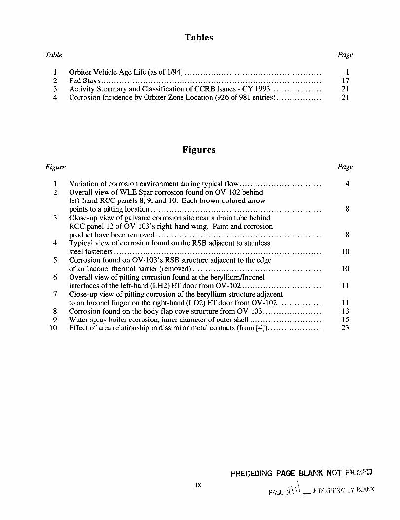
Table
1
2
3
4
Tables
Orbiter Vehicle Age Life (as of 1/94) ....................................................
Pad Stays ....................................................................................
Activity Summary and Classification of CCRB Issues - CY 1993 ...................
Corrosion Incidence by Orbiter Zone Location (926 of 981 entries) .................
Page
1
17
21
21
Figure
1
2
Figures
Variation of corrosion environment during typical flow ...............................
Overall view of WLE Spar corrosion found on OV-102 behind
left-hand RCC panels 8, 9, and 10. Each brown-colored arrow
points to a pitting location .................................................................
3 Close-up view of galvanic corrosion site near a drain tube behind
RCC panel 12 of OV-103's right-hand wing. Paint and corrosion
product have been removed ...............................................................
4 Typical view of corrosion found on the RSB adjacent to stainlesssteel fasteners ...............................................................................
5 Corrosion found on OV-103's RSB structure adjacent to the edgeof an Inconel thermal barrier (removed) .................................................
6 Overall view of pitting corrosion found at the beryllium/Inconel
interfaces of the left-hand (LH2) ET door from OV-102 ..............................
7 Close-up view of pitting corrosion of the beryllium structure adjacentto an Inconel finger on the right-hand (LO2) ET door from OV- 102 ................
8 Corrosion found on the body flap cove structure from OV-103 ......................
9 Water spray boiler corrosion, inner diameter of outer shell ...........................
10 Effect of area relationship in dissimilar metal contacts (from [4]) ....................
Page
4
8
8
10
10
11
1113
15
23
ix
HRECEDING PAGE BLANK NOT , _A,_-D
PAGE__._X INfENi-!ONAILY [_AN'<

A&P
APU
ATP
CAR
CCRB
CPC
CRES
DHSDR
ECOEICN
ET
FAA
FCPV
FRCS
GGVM
KSC
LCCLH
LRU
LSOC
MCR
MDDMLP
MMH
M&P
MPS
MR
MRB
MUA
N204
N2H4NASA
NDE
NH3NSLD
OMDP
Acronyms and Abbreviations
airframe and power plant
auxiliary power unit
acceptance test procedure
corrective action requestCorrosion Control Review Board
corrosion preventive compoundscorrosion resistant steel
dome heat shield
discrepancy report
engineering change orderend item control numberexternal tank
Federal Aviation Administration
false alarm avoidance
forward reaction control system (subsystem)
gas generator valve module
Kennedy Space Center
Launch Control Centerleft-hand
line replaceable unit
Lockheed Space Operations Company
material change requestmate/demate device
Mobile Launch Platformmaintenance man-hour
monomethylhydrazine
materials and processes
main propulsion system(subsystem)material review
material review board
material usage agreement
nitrogen tetroxide
hydrazine
National Aeronautics and Space Administrationnondestructive evaluation
ammonia
NASA Shuttle Logistics Depot
orbiter maintenance down period
xi t.'RECEDING P_].qE BLANK NL;,__ F_.:':;:i:iL9
p.:.r,E_./__ ..... tr,rf pNi!O_;r,_i Y !_.."T,'
OMRSD
OMS
OJTOPF
PC
PR
PRACA
PRSD
QA
QcQE
RCC
RCN
RH
RI-LSSRSB
RTB
RTV
SCASCC
SMSG
SSME
STS
TCS
TPSTRSD
VAB
WAD
WLE
Operations Maintenance Requirements Specifications Documentorbiter maneuvering system(subsystem)
on-the-job training
Orbiter Processing Facility
personal computer
problem report
problem reporting and corrective action
power reactant storage and distribution
power reactant supply and distribution system
quality assurance
quality controlquality engineering
reinforced carbon to carbon
requirements change notice
right-hand
Rockwell International Corporation-Launch Support Service
rudder speed brake
resistance temperature bulb
room temperature vulcanized (silicone compound)
Shuttle Carrier Aircraft
stress corrosion cracking
Shuttle Maintenance Steering Group
space shuttle main engine
Space Transportation System
thermal control system(subsystem)
thermal protection system
Test Requirements Specification Document
Vehicle Assembly Building
Work Authorizing Document
wing leading edge
xii
!
1.0 Introduction
1.1 Overview and Intent
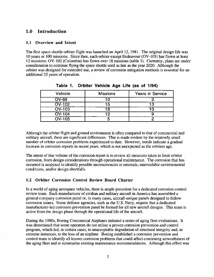
The first space shuttle orbiter flight was launched on April 12, 1981. The original design life was
10 years or 100 missions. Since then, each orbiter except Endeavour (OV-105) has flown at least
12 missions; OV-102 (Columbia) has flown over 18 missions (table 1). Currently, plans are under
consideration to continue flying the space shuttle until as late as the year 2020. Although theorbiter was designed for extended use, a review of corrosion mitigation methods is essential for an
additional 25 years of operation.
Table 1.
Vehicle
0V-99
OV- 102
OV- 103
OV- 104
0V-105
Orbiter Vehicle Age Life (as of 1/94)
Missions Years in Service
10 3
15
18
13
10
12 9
5 2
Although the orbiter flight and ground environment is often compared to that of commercial andmilitary aircraft, there are significant differences. This is made evident by the relatively small
number of orbiter corrosion problems experienced to date. However, trends indicate a gradual
increase in corrosion reports in recent years, which is not unexpected as the orbiters age.
The intent of this volume of the corrosion report is to review all measures taken to limit orbiter
corrosion, from design considerations through operational maintenance. The corrosion that has
occurred is analyzed to identify possible inconsistencies in rationale, unavoidable environmental
conditions, and/or design shortfalls.
1.2 Orbiter Corrosion Control Review Board Charter
In a world of aging aerospace vehicles, there is ample precedent for a dedicated corrosion control
review team. Each manufacturer of civilian and military aircraft in America has assembled a
general company corrosion panel or, in many cases, aircraft-unique panels designed to follow
corrosion issues. Some defense agencies, such as the U.S. Navy, require that a dedicated
manufacturer-led corrosion prevention panel be formed for all new aircraft designs. This team isactive from the design phase through the operational life of the aircraft.
During the 1980s, Boeing Commercial Airplanes initiated a series of aging fleet evaluations. It
was determined that some operators do not utilize a proven corrosion prevention and control
program, which led, in certain cases, to unacceptable degradation of structural integrity and, in
extreme instances, to the loss of an airplane. Boeing established a corrosion prevention and
control team to identify all known corrosion problems that could affect continuing airworthiness of
the aging fleet and to summarize existing maintenance recommendations. Although this effort was
initially performedto addresstheagingfleet,Boeingstressesthatsuchprogramsshouldbeinitiatedearly,becausethecorrosionthresholdof somestructuresisasshortas5to 6years.
In July 1993,theOrbiterProjectCorrosionControlReviewBoard(CCRB)wasestablishedandcharteredto advisetheProjectandinitiateresolutionsfor technicalandoperationalactivitiesinvolving corrosion.Specificresponsibilitiesincludecorrosionassessment,correctiveactions,andcorrosioncontrolandprevention.
TheCCRBreviewsactivecorrosionissuesandensuresthattheappropriatepersonnelareinvolvedin theirresolution.Appropriatepersonnel,at minimum,includerepresentativesfrom system,materials,andqualityengineeringareas.A list of activecorrosionissuesisupdatedcontinuouslythroughinputsfrom projectmanagement,systemmanagers,andacorrosiondatabasewhich isderivedfrom theOrbiterProblemReportingandCorrectiveAction (PRACA)System.In keepingwith theproactiveandpreventivenatureof theCCRB,additionalcorrosionissuesarealsoconsidered.Teleconsareconductedto review,status,andobtainconsensusonactivecorrosionissues. Summariesarepreparedasrequiredfor theorbiterprojectandsubsystemmanagement.
By December1993,28corrosionissueswereidentifiedassignificantenoughto requireCCRBreview. Fifteenissueswereresolved,withCCRBrecommendationsimplementedand/orforwardedto theappropriatemanagementoffice. Themostnotableissuein 1993wasexternalrudderspeedbrake(RSB)corrosion.A resolutioninvolvingstrippingandrepaintingtheRSBandperformingregularwashesatKennedySpaceCenter(KSC)wasdevelopedby theCCRBandapprovedby thesubsystemmanagerandtheManager,OrbiterandGFEProjectsoffice.
1.3 KSC Corrosion Database
A corrosion database was created by the KSC CCRB representatives via a historical review of the
KSC PRACA database, which was established in 1983. The PRACA database tracks all
nonconformances reported on shuttle hardware detected at KSC, at Palmdale during orbiter
maintenance down period (OMDP), or in flight. The nonconformances (problem reports (PRs)
and material reviews (MRs)) are input into the PRACA database when detected; each entry includesall information found in the 39 numbered data points on the first page of the referenced work
authorizing document (WAD). Entries are updated daily with resulting disposition and summary
as required, until the WAD is closed.
The PRACA database was searched for the problem description and disposition summary for all
entries written against orbiter vehicle corrosion. This search used the key words corrosion,crack(s), scratch(es), discoloration, stain(s), rust, oxidation, pit(s), pitting, foreign, erosion and
scored. The following data points were selected from the 39 possible as output: PR number,
status, when detected, work area, orbiter location, orbiter zone, report date, end item control
number (EICN) 1 & 2, part name, part number, serial number, replacement serial number, STS
effectivity, datacode, description, and disposition. After reviewing the data from this initial query,
the key word list was reduced to corrosion, rust, oxidation and pits�pitting, resulting in a more
efficient and usable output.
The PRACA entries concerning corrosion targeted by this historical query were entered into a
database by RI-LSS personnel utilizing Macintosh Filemaker@ software. The Filemaker database
is more user friendly and flexible than the KSC PRACA system; it can be accessed through
networks by both Macintosh and PC workstations. Information provided through the KSC
PRACA system is presently being provided for entry into the Filemaker database on a monthly
2
basisandincludes those WADs that have been closed since initial entry and open WADs written
within the previous month. In this manner all WADs initially entered as open will be updated and
the summary rationale added to complete the entry. Monthly updates reflect certain milestones in
orbiter processing; i.e., the quantity of new WADs increases at roll-in to the Orbiter Processing
Facility (OPF), while WADs closure increases at roll-out from the OPF and before launch.
Currently, efforts are under way by RI-LSS personnel to include corrosion information not located
in the KSC PRACA database. Data sources include the corrective action request (CAR) databasemaintained by Rockwell at Downey and a database under development at the NASA Shuttle
Logistics Depot (NSLD). The CAR database includes all Shuttle Project CARs generated over the
life of the program. The NSLD database will include those WADs initiated at the NSLD. Queries
of these databases will provide data on corrosion that may be invisible to the KSC PRACA system,
i.e., data obtained upon tear down and failure analysis of a part or subsystem. The addition of
these sources to the database will provide a more complete historical overview of a corrosion issue.The goal of the database is to aid in real-time corrosion problem solving and tracking, as well as to
provide trend analysis through historical data.
2.0 Design Considerations
2.1 Predicted Corrosion Environment
The Space Shuttle experiences corrosion environments from benign to severe as it progresses from
flight to flight. The relative severity, as evaluated by the CCRB, of each environment is illustrated
in figure 1. The orbiters are stored in the OPF, in which buildings are temperature- and humidity-
controlled. When moved to the launch pad, each orbiter is subjected to an almost constant salt
spray from the nearby Atlantic Ocean. In addition, the high humidity allows the formation of
condensation on all surfaces open to the atmosphere. Once the orbiter reaches low earth orbit, any
water that may have collected during earlier exposure evaporates in the vacuum of space. Onlanding, the orbiter must be deserviced; during this period it is exposed to whatever the
environment is at the landing site. If the orbiter lands in California, it must be ferried across the
country to KSC. This is additional exposure to an uncontrolled environment until the orbiter
returns to the OPF. All these factors were taken into account when the overall corrosion protection
scheme was developed.
2.2 General Guidelines
Rockwell's proposal for corrosion protection of the orbiter was based on no structural failure due
to corrosion within a 10-year or 100-mission life. A detailed material control plan addressing
every material that would be utilized on the orbiter was implemented. The plan required that all
metals meet what was termed an 'A' rating for corrosion and/or stress corrosion. Metallic
materials were evaluated either by test or engineering judgment to meet these NASA Level 11
requirements.
Metals were required to meet MSFC-SPEC-250, class II requirements. Metals not listed in the
specification were subjected to a 1500-hour salt spray test. Metallic materials that were proposed
for use but not 'A' rated by MSFC-SPEC-250 (accepted for unrestricted use with respect to
corrosion) were evaluated by their use, location, or protection schemes and upgraded to 'A' status
if possible.

"EEe"o
.m>t-
LI.I
¢.-._o
oO
O
"6
'r-
>O
._>
®rr
OPF •,_ VAB PAD v Orbit Land Ferry
Figure 1. Variation of corrosion environment during typical flow.
Rockwell used MSFC-SPEC-522 as a guideline for determining the rating of material for stress
corrosion cracking (SCC). For instance, the requirement for aluminum alloys is freedom from
cracking after 30 days alternate exposure in a 3.5% sodium chloride solution while stressed to 75%of the material's yield strength. However, where essential materials were used that did not meet
the 'A' rating, the designer would consider, as a minimum, the following actions to reduce the
probability of stress corrosion:
a) Selecting less susceptible alloys or tempers.
b) Reducing sustained stress levels on the part below stress corrosion threshold levels.
c) Protecting the part from the detrimental environment by hermetically sealing or coating the part
or by inhibiting the environment.d) Avoiding or reducing residual stresses in parts or assemblies by stress relieving, by avoiding
interference fits, or by shimming assemblies.
e) Avoiding galvanic couples which may tend to accelerate the stress corrosion.
f) Providing for regular inspection of parts to determine surface flaws and cracking during the life
cycle of the part.
g) Improving the surface quality of the part by reducing surface roughness or increasing surface
compressive stresses.
Approval of any of these actions again had to be approved by Rockwell M&P and NASA through
a material usage agreement (MUA).
Additionally, the Rockwell Standard Design Manual restricts the use of galvanically dissimilar
metals by requiting that they not be used in contact unless suitably protected against electrolytic
corrosion. Faying surfaces of dissimilar metals must be sealed against water intrusion or separated
with a layer of corrosion-inhibiting epoxy or room-temperature vulcanized (RTV) silicone rubber.
Dissimilar metals were considered compatible if they were in the same grouping as specified in
MSFC-SPEC-250, or if the difference in potential was < 0.25 volts. Also imposed was the
4
j'
requirement that all fasteners be installed wet with epoxy. The epoxy of choice was a chromated
primer known under the brand name Super Koropon.
To address specific corrosion problems associated with aluminum alloys, additional restrictions
were applied. Alloys susceptible to exfoliation were eliminated from design consideration as wereall forms of alloys that exhibit stress corrosion thresholds of less than 25 KSI.
2.3 Special Considerations
A dry nitrogen gas system was implemented to purge the interior spaces of the orbiter vehicle. Thepurpose of the purge is to maintain a dry environment by preventing condensation. The nitrogen
purge is continuously operating while the vehicle is in the Vehicle Assembly Building (VAB) and
again, once the vehicle has been mounted on the Mobile Launch Platform (MLP). To date, there
have been no significant corrosion issues in any areas of the vehicle maintained with this purge.
2.4 Water Intrusion/Entrapment Design Features
Drain holes were designed into the orbiter to prevent water from accumulating within the open
orbiter structure. The drains were placed in selected areas of the structure so that drainage willoccur in both horizontal and vertical orientations.
3.0 Inspection And Reporting
3.1 Inspection Requirements
Most of the orbiter recurring inspection requirements originate from the Operations Maintenance
Requirements and Specification Document (OMRSD) V30 (Air Frame Inspection) and V31 (Zonal
Ingpection) documents. As indicated by Note R-2 adjacent to V30GEN.010 para. 3.2.2, "The
inspection requirements in this document are designed to detect damage/deterioration resulting from
service and age." The inspector is to verify that there are no cracks or corrosion in the structure orin fillet radii and notched areas.
There are four levels of inspections. Level A, External Surveillance, is used for detectingobvious discrepancies in externally visible structure, systems, and components. Level B. Internal
Surveillance, is used for detecting similar conditions in internal structure. Level B may include the
use of a borescope.
Level C, Detailed, is an intensive visual check of a specified area. Inspection aids such as mirrors
or a hand lens may be required, and a borescope is recommended when access is confined. This
inspection level, however, has been the source of some misunderstanding in the past. This is
because the V30-10001 Job Card defines the distance to be used for this inspection level normallyto be not greater than 18 inches. Areas found to be suspect at this distance should then be
examined more closely to confirm findings. It is noted that minor corrosion may therefore not be
detected using Level C. This is not an indication that the inspection was performed improperly,but that the corrosion was too minor to be seen at 18 inches.
LevelD, SpecialDetailed,isanintensivecheckof aspecifiedlocationwhichincludesaspecialtechnique,suchasnondestructiveevaluation(NDE) orhigh-magnificationborescope,andforwhichsomedisassemblymayberequired.
Therequirementsfor inspectionfrequencyvary in accordance with OMRSD requirements. For
example, some inspections are performed every flight, some have a five-flight interval between
inspections, and some are performed only at orbiter maintenance down period (OMDP). Detection
of corrosion in a particular area has resulted in initiation of a requirements change notice (RCN) to
change the inspection level or frequency. Or the area may be called out as a specific point of
interest to be examined in future inspections. Thus, once corrosion is found in an area, that area is
commonly inspected with the awareness that it has had a history of corrosion.
Additional inspections are required as a result of PRs and special requests from KSC and JSC
engineering organizations. Subsystems have individual inspection requirements in the OMRSD aswell.
3.2 Inspection Methods
Most inspections for corrosion on the orbiter are visual. Inspection Levels A, B, and C (noted
previously) are visual checks, which may include use of a borescope, flashlight, hand lens
(typically 5X or 10X), and mirror. Removal of fairings, access doors, thermal control system
(TCS), liners, etc. may be required, as well as surface cleaning.
Inspection Level D, Special Detailed, uses a high-magnification borescope or NDE methodsincluding penetrant testing, eddy current, ultrasonic, or X-radiography. These methods have been
augmented with photography and videotape recording. Corrosion pit depth measurements havebeen made with dental molds.
Visual inspections performed apart from normal processing and the OMRSD-required checks havealso detected corrosion. Teardown and refurbishment activities at the manufacturer and at NSLD
have detected corrosion in hardware that was not evident via other means.
Other methods for detecting corrosion include various modes of hardware performance
degradation. Examples include pressure loss in the ammonia boiler heat exchanger, flow rate
reduction in the Freon cooling loop, and fuel cell leakage causing manifold pressure decay.
3.3 Corrective Action Reporting (CAR) Process
When corrosion and other anomalies deviating from design specifications are detected, they are
reported using PRACA. Information from this computerized system is available at Rockwell-
Downey, JSC, and KSC, and includes problem description, part number, probable cause, and
disposition. The purpose of the problem reporting system is to ensure adequate visibility of
nonconformances that require engineering input for resolution.
A proposed repair for a problem that cannot be resolved by returning the discrepant hardware todesign specification requires approval of the Material Review Board (MRB). The MRB is an
element project-level engineering and quality board chaired to review nonconforming material.
6
Recurringproblemsdetectedin flight hardwareareaddressedthroughcorrectiveactionandrecurrencecontrol. Action is takento correct,reducetheincidenceof, andpreventtherecurrenceof nonconformances.
4.0 Structural Corrosion History
Throughout orbiter history, numerous discrepancy reports have been written to documentcorrosion on many different flight hardware assemblies. Most of these discrepancies indicate
minor structural surface corrosion. In these cases, the corrosion is removed mechanically or
chemically, and the surface coating is reapplied. This repair is performed only when the structural
integrity of the assembly can be maintained. When the corrosion has been severe enough to affect
the margin of safety, doublers have been added, e.g., wing leading edge (WLE) spar and rudder
speed brake (RSB) panels. In some instances, corrosion of fasteners has been severe enough to
warrant removal and replacement. In areas where galvanic (dissimilar metal) corrosion has
occurred and the Koropon protective coating was insufficient, a barrier layer of RTV may have
been added to prevent recurrence. It is important to note that all structural corrosion instances are
evaluated on a case-by-case basis (see section 5.1).
4.1. Fleet-Wide Corrosion Issues
Following is a list of selected issues from the KSC PRACA database as tracked by the CCRB:
a. Wing Leading Edge Spars. The WLE spar is constructed of either an aluminum honeycomb
sandwich panel (OV-102) or a corrugated aluminum alloy approximately 0.040 inches thick
(OV-103 and subs). The leading edge surfaces are lined with Inconel thermal control system
(TCS) blankets. Attached spar fittings hold the reinforced carbon to carbon (RCC) panels
which give the wing its characteristic airfoil shape and thermal protection. Three of the 22 RCC
panels and the associated Inconel TCS blankets and spar fittings are removed at each orbiterprocessing flow to perform a sampling type inspection of the WLE for corrosion, with a
contingency that the entire wing spar be inspected between OMDP periods. The forward
surfaces of the corrugations are coated with room temperature vulcanization (RTV) to inhibit
the formation of dissimilar metal corrosion. However, the set-back surfaces have only the
basic chem-film and three coats of Koropon. Pitting corrosion has been noted on these set-
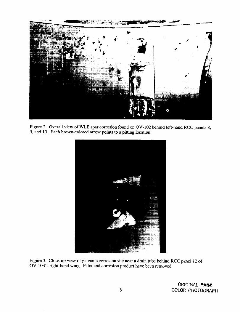
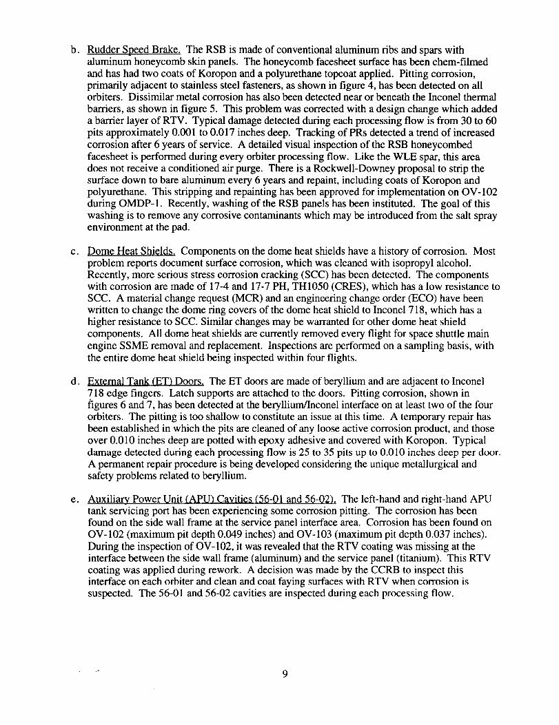
back surfaces, particularly near drain tubes. Figure 2 shows an overview of corrosion foundon the WLE behind three adjacent RCC panels on OV-102. The pattern of the pitting suggests
a galvanic effect due to the drain tube, as shown in figure 3. This area does not receive a
conditioned GN2 purge. Typical damage detection during a flow is approximately 30 pits per
wing averaging 0.010 inches deep.
&
Figure 2. Overall view of WLE spar corrosion found on OV-102 behind left-hand RCC panels 8,9, and 10. Each brown-colored arrow points to a pitting location.
Figure 3. Close-up view of galvanic corrosion site near a drain tube behind RCC panel 12 ofOV-103's right-hand wing. Paint and corrosion product have been removed.
8
ORIGrNAL I_
COLOR PHOTOGRAPH
b.
C.
d.
eo
Rudder Speed Brake. The RSB is made of conventional aluminum ribs and spars with
aluminum honeycomb skin panels. The honeycomb facesheet surface has been chem-filmed
and has had two coats of Koropon and a polyurethane topcoat applied. Pitting corrosion,primarily adjacent to stainless steel fasteners, as shown in figure 4, has been detected on allorbiters. Dissimilar metal corrosion has also been detected near or beneath the Inconel thermal
barriers, as shown in figure 5. This problem was corrected with a design change which added
a barrier layer of RTV. Typical damage detected during each processing flow is from 30 to 60
pits approximately 0.001 to 0.017 inches deep. Tracking of PRs detected a trend of increased
corrosion after 6 years of service. A detailed visual inspection of the RSB honeycombed
facesheet is performed during every orbiter processing flow. Like the WLE spar, this areadoes not receive a conditioned air purge. There is a Rockwell-Downey proposal to strip the
surface down to bare aluminum every 6 years and repaint, including coats of Koropon and
polyurethane. This stripping and repainting has been approved for implementation on OV-102
during OMDP- 1. Recently, washing of the RSB panels has been instituted. The goal of this
washing is to remove any corrosive contaminants which may be introduced from the salt sprayenvironment at the pad.
Dome Heat Shields. Components on the dome heat shields have a history of corrosion. Most
problem reports document surface corrosion, which was cleaned with isopropyl alcohol.Recently, more serious stress corrosion cracking (SCC) has been detected. The components
with corrosion are made of 17-4 and 17-7 PH, TH1050 (CRES), which has a low resistance to
SCC. A material change request (MCR) and an engineering change order (ECO) have been
written to change the dome ring covers of the dome heat shield to Inconel 718, which has a
higher resistance to SCC. Similar changes may be warranted for other dome heat shield
components. All dome heat shields are currently removed every flight for space shuttle main
engine SSME removal and replacement. Inspections are performed on a sampling basis, with
the entire dome heat shield being inspected within four flights.
External Tank (ET) Doors. The ET doors are made of beryllium and are adjacent to Inconel
718 edge fingers. Latch supports are attached to the doors. Pitting corrosion, shown infigures 6 and 7, has been detected at the beryllium/Inconel interface on at least two of the four
orbiters. The pitting is too shallow to constitute an issue at this time. A temporary repair has
been established in which the pits are cleaned of any loose active corrosion product, and those
over 0.010 inches deep are potted with epoxy adhesive and covered with Koropon. Typical
damage detected during each processing flow is 25 to 35 pits up to 0.010 inches deep per door.
A permanent repair procedure is being developed considering the unique metallurgical and
safety problems related to beryllium.
Auxiliary Power Unit (APU) Cavities (56-01 and 56-02). The left-hand and right-hand APU
tank servicing port has been experiencing some corrosion pitting. The corrosion has been
found on the side wall frame at the service panel interface area. Corrosion has been found on
OV-102 (maximum pit depth 0.049 inches) and OV-103 (maximum pit depth 0.037 inches).
During the inspection of OV-102, it was revealed that the RTV coating was missing at the
interface between the side wall frame (aluminum) and the service panel (titanium). This RTV
coating was applied during rework. A decision was made by the CCRB to inspect thisinterface on each orbiter and clean and coat faying surfaces with RTV when corrosion is
suspected. The 56-01 and 56-02 cavities are inspected during each processing flow.
• _ 9
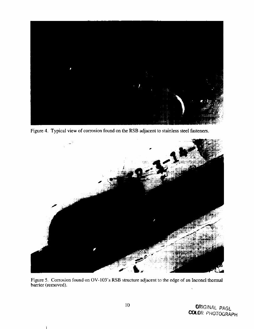
Figure 4. Typical view of corrosion found on the RSB adjacent to stainless steel fasteners.
Figure 5. Corrosion found on OV-IO3's RSB structure adjacent to the edge of an Inconel thermalbarrier (removed).
10ORIGINAL PAGE
COLOR PHOTOGRAPH
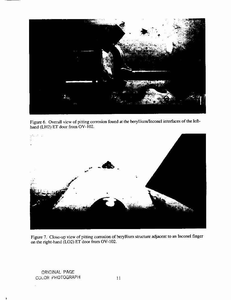
Figure 6. Overall view of pitting corrosion found at the beryllium/Inconel interfaces of the left-
hand (LH2) ET door from OV-102.
Figure 7. Close-up view of pitting corrosion of beryllium structure adjacent to an Inconel finger
on the right-hand (LO2) ET door from OV-102.
ORIGINAL PAGE
COLOR PHOTOGRAPH 11
4.2 Selected Unique Corrosion Issues
The following corrosion issues that have been addressed by the CCRB are not considered fleet-wide problems:
a. OV-102 Left-Hand (LH) Inboard Elevon. The OV-102 LH inboard elevon trailing edge,
which is a honeycomb sandwich, was discovered to have a one-square-inch area of facesheet
and core corroded away. It was determined to have been caused by improper sealing andplacement of the elevon drain hole. The damage was repaired and the drain hole was relocated.
The other vehicles are being inspected during OMDP for proper drain hole placement.
b. OV-102 Right-Hand (RH) Outboard Elevon. Scratches with corrosion were found in
approximately 85 locations on OV-102's RH outboard elevon. The maximum pit depth was0.004 inches. Possible causes were identified as (1) undetected corrosion in the skin at time of
manufacture with subsequent application of Koropon and/or (2) scratches caused by impropertile removal.
C. Wing Carry-Through Spar. V30 inspections have discovered corrosion of the wing carry-through spar structures on OV-102 and OV-103. On OV-102 corrosion was found near the
lower skin to 1307 bulkhead, three areas on the LH side (with a maximum pit depth of 0.0245
inches), and one area on the RH side (with pit depth of 0.0047 inches). On OV-103 corrosion
was found around Hi-loks on the RH and LH 1307 bulkhead fittings and on various areas on
the RH and LH lower bulkhead. The deepest pit found on OV-103 was 0.016 inches. All
areas were cleaned and the corrosion was blended out, followed by applications of chem-filmand Koropon to return the areas to print.
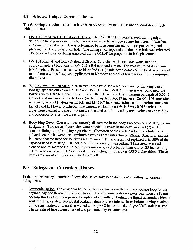
d. Body Flap Cove. Corrosion was recently discovered in the body flap cove of OV-103, shownin figure 8. Two areas of corrosion were noted: (1) rivets in the cove area and (2) at the
actuator fitting to airframe faying surfaces. Corrosion of the rivets has been attributed to a
galvanic couple between the aluminum rivets and titanium actuator fittings. Structural analysisindicated that the need for the rivets was minimal. The rivets are not replaced until 30% of the
exposed head is missing. The actuator fitting corrosion was pitting. These areas were all
cleaned and re-Koroponed. Mold impressions revealed defect dimensions 0.623 inches long,0.195 inches wide and 0.023 inches deep; the fitting in this area is 0.080 inches thick. These
items are currently under review by the CCRB.
5.0 Subsystem Corrosion History
In the orbiter history a number of corrosion issues have been documented within the various
subsystems.
a° Ammonia Boiler. The ammonia boiler is a heat exchanger in the primary cooling loop for thepayload bay and the cabin instrumentation. The ammonia boiler removes heat from the Freon
cooling fluid as the Freon passes through a tube bundle by boiling the liquid ammonia which is
vented off the orbiter. Accidental contamination of these tube surfaces before brazing resulted
in the sensitization of these thin walled tubes (0.008 inches) made of type 304L stainless steel.The sensitized tubes were attacked and penetrated by the ammonia.
12
Figure8. Corrosionfoundon thebodyflapcovestructurefrom OV-103.
b.
The corrective action was to change the tubing to 347 stainless steel, which is not susceptible to
the chromium carbide segregation, and to upgrade cleaning procedures to preventcontamination.
APU Gas Generator Valve Seats. The APU gas generator valve module (GGVM) utilizes four
tungsten carbide valve seats to regulate hydrazine flow to the catalyst bed. The 5 mm diametervalve seats have sealing lands that are only 0.115 to 0.150 mm wide.
The seats are manufactured from sintered KZ-96 tungsten carbide containing 5% cobalt as a
binder. In mid-1985, valve leakage problems during acceptance tests were traced to a
breakdown of the valve seat lands. After an APU was shut down during a flight,contamination traces were found on one of the valve seats. The manufacturer instituted a
revised cleaning process involving a hot water rinse for both production and refurbishment.
Shortly after that, the valve seat lands began experiencing an extremely high rejection rate
during acceptance test procedure (ATP). A subsequent failure analysis indicated that the hot
water was leaching the cobalt binder from the valve seat lands.
A few years later, the valve seats began experiencing frequent leaking problems. Failure
analysis indicated that ammonium hydroxide formed by the decomposition products ofhydrazine and water condensation from the atmosphere backflowing down the vent duct were
apparently initiating a cobalt leaching problem similar to that experienced previously. Tests
proved that such exposure induced leaching and subsequent impacting of the lands by the valve
poppets resulted in breakdown of the seats and the noted leakage problems.
ORIG'M,',, ,,'-- PAGLCOLOR PHOTOGRAPH
13
C.
d°
e.
APU Injector Tubes. The injector tube of the orbiter APU carries hydrazine fuel to the catalystbed, where it is heated and decomposes. The hot decomposed gases drive a turbine wheel to
generate secondary power for spacecraft systems. Shortly after touchdown from the ninth
launch of the orbiter, two of the three APUs experienced fires. Extensive investigation
determined that the fires resulted when hydrazine leaked through cracks in the Hastelloy nickel-based alloy B injector tube walls while on orbit and froze on exterior surfaces, and then melted
and ignited during reentry.
The fractures on each tube were intergranular, starting on the inside diameter, and occurred in
the same location. The cracks were determined to be caused by stress corrosion. It was
determined that ammonia or ammonium hydroxide were the only potential fluids that could
cause SCC on the Hastelloy B. The ammonia vapors resulted from the decomposition of the
hydrazine in the catalyst bed. Moisture, resulting in the formation of ammonium hydroxide,
was available from the atmosphere migrating back through the exhaust duct. Misalignment ofthe tubes during installation resulted in the stresses. A sensitized microstructure was also
found, and was determined to be a result of carbon deposition during the electrical discharge
machining (EDM) of the injector tubes.
The solution was to eliminate the preload stresses on the injector tubes by instrumenting theinstallation and to eliminate the sensitized carbide network by reaming the tube inside diameter
and by revising the braze process to ensure even distribution of any carbides. Later tubes werealso coated with a thin chromized layer.
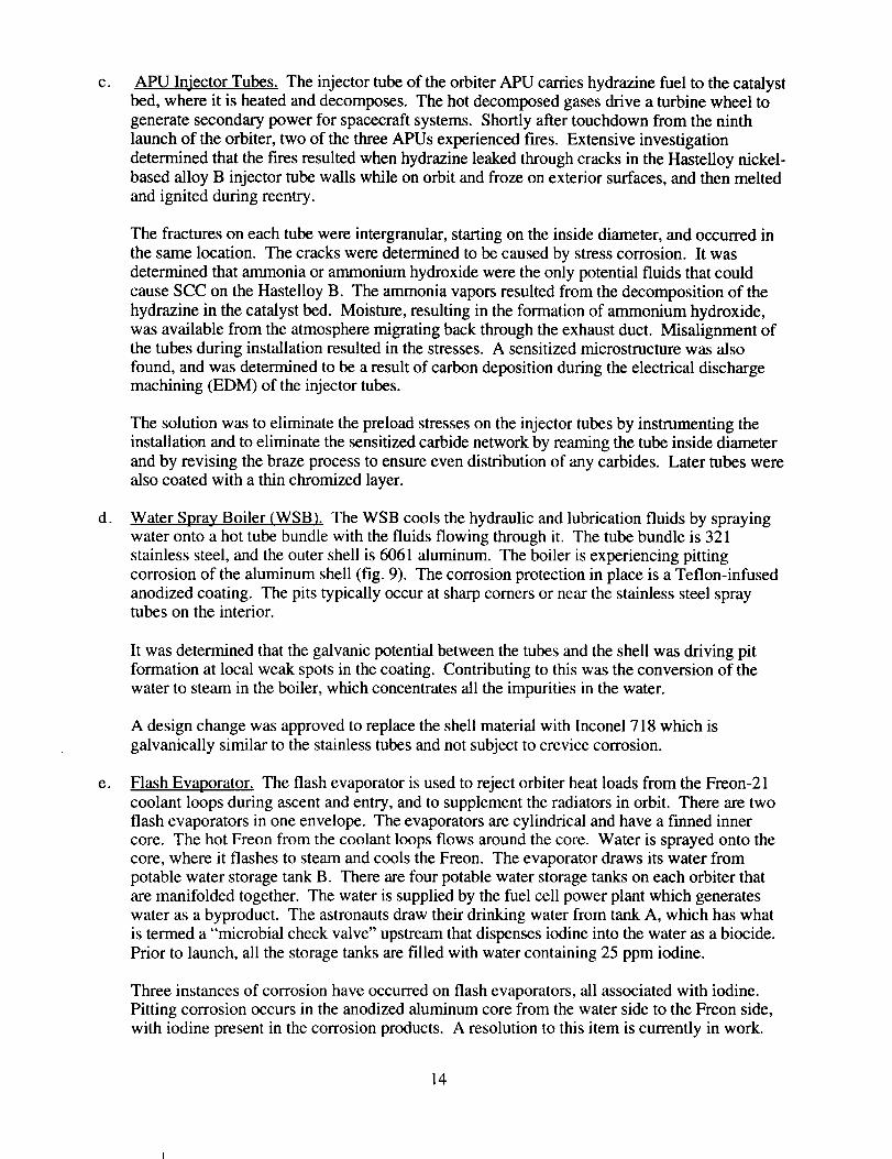
Water Spray Boiler (WSB). The WSB cools the hydraulic and lubrication fluids by sprayingwater onto a hot tube bundle with the fluids flowing through it. The tube bundle is 321
stainless steel, and the outer shell is 6061 aluminum. The boiler is experiencing pitting
corrosion of the aluminum shell (fig. 9). The corrosion protection in place is a Teflon-infused
anodized coating. The pits typically occur at sharp comers or near the stainless steel spraytubes on the interior.
It was determined that the galvanic potential between the tubes and the shell was driving pit
formation at local weak spots in the coating. Contributing to this was the conversion of thewater to steam in the boiler, which concentrates all the impurities in the water.
A design change was approved to replace the shell material with Inconel 718 which is
galvanically similar to the stainless tubes and not subject to crevice corrosion.
Flash Evaporator. The flash evaporator is used to reject orbiter heat loads from the Freon-21
coolant loops during ascent and entry, and to supplement the radiators in orbit. There are two
flash evaporators in one envelope. The evaporators are cylindrical and have a finned inner
core. The hot Freon from the coolant loops flows around the core. Water is sprayed onto the
core, where it flashes to steam and cools the Freon. The evaporator draws its water from
potable water storage tank B. There are four potable water storage tanks on each orbiter thatare manifolded together. The water is supplied by the fuel cell power plant which generates
water as a byproduct. The astronauts draw their drinking water from tank A, which has what
is termed a "microbial check valve" upstream that dispenses iodine into the water as a biocide.
Prior to launch, all the storage tanks are filled with water containing 25 ppm iodine.
Three instances of corrosion have occurred on flash evaporators, all associated with iodine.
Pitting corrosion occurs in the anodized aluminum core from the water side to the Freon side,
with iodine present in the corrosion products. A resolution to this item is currently in work.
14
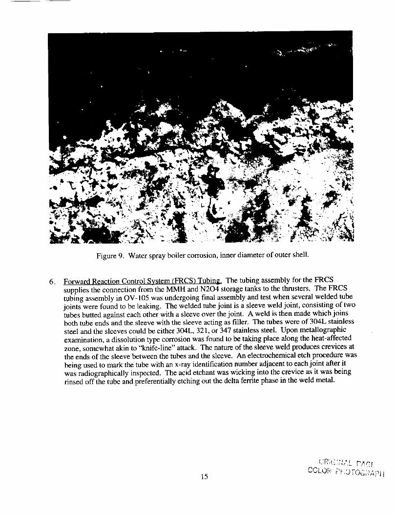
Figure 9. Water spray boiler corrosion, inner diameter of outer shell.
, Forward Reaction Control System (FRCS) Tubing. The tubing assembly for the FRCS
supplies the connection from the MMH and N204 storage tanks to the thrusters. The FRCStubing assembly in OV-105 was undergoing final assembly and test when several welded tube
joints were found to be leaking. The welded tube joint is a sleeve weld joint, consisting of two
tubes butted against each other with a sleeve over the joint. A weld is then made which joinsboth tube ends and the sleeve with the sleeve acting as filler. The tubes were of 304L stainless
steel and the sleeves could be either 304L, 321, or 347 stainless steel. Upon metallographic
examination, a dissolution type corrosion was found to be taking place along the heat-affected
zone, somewhat akin to "knife-line" attack. The nature of the sleeve weld produces crevices atthe ends of the sleeve between the tubes and the sleeve. An electrochemical etch procedure was
being used to mark the tube with an x-ray identification number adjacent to each joint after it
was radiographically inspected. The acid etchant was wicking into the crevice as it was beingrinsed off the tube and preferentially etching out the delta ferrite phase in the weld metal.
15
dR,_ ,,",",,,,__PAnUCULOP :_u_'.... _-
6.0 Unanticipated Environments
6.1 Extended Pad Stays
Normal STS processing includes a scheduled period at the pad for payload installation, final
servicing, and checkout prior to launch. The average pad stay is approximately 31 days. During
twelve pad stays, problems that arose with the flight hardware extended the time normally spent atthe pad. The longest time spent at the pad was 166 days prior to OV-102's tenth flight. Table 2summarizes the pads stays for each vehicle.
These extended stays at the pad are of concern to the CCRB. The pad is located a few hundred
yards from the ocean. The coast exposure is very severe because of the heat, high humidity, saltair, and the daily condensation of dew deposited onto the orbiter structure. The orbiter TPS
bonding system provides adequate corrosion protection under most circumstances. Exterior
assemblies on the orbiter that are not covered by the thermal protection system (RSB, WLE spar,and ET doors) are primed with Koropon and in some cases also painted. Condensation can occur
on these surfaces, which may initiate corrosion activity when the primer/paint barrier is violated.
These areas have shown repetitive corrosion problems, as stated earlier in this report. The CCRB
is actively working to address these corrosion issues. A possible solution is expanding the presentpurge system to cover additional areas.
6.2 Pad Firex System
The pad is equipped with a Firex system that is activated when fire hazards, including gas leaks,are detected near the orbiter. The system is designed to spray the specific external area of theorbiter where a fire hazard has been detected.
The water used in the Firex system is filtered, untreated water. Since a main engine abort normallyrequires a minimum of a week to resolve, the designed drainage system along with normal
evaporation should dry out these areas. Although the water in the tank reservoir is filtered, theremay be stagnant water in the lines that contain various ionic contaminants. This water could act as
an electrolyte if introduced into the orbiter.
There are three systems which make up the Firex system at the pad. It is suspected that past usesof these systems may have contributed to previous structural corrosion problems. These systemsand the times they have been used:
Orbiter SSME Water Deluge System--This system is automatically turned on by the ground
launch sequencer during an abort. This deluge covers the main engine nozzles/heat shield area
and the 17" disconnect area. During operation of this system, the Rudder Speed Brake is
subject to a considerable amount of deluge. This system operates for 2-10 minutes, dependingon the abort conditions. The system is manually shut down.
Times used: OV-099, 41C; OV-103, 51A; OV-099, 51F; OV-103, STS-26R FRF; OV-105,STS-49 FRF; OV-102, STS-55; OV-103, STS-51; OV-105, STS-68.
16
Table 2. Pad Stays
STS FLTOV-102 STS-1 1"
STS-2 2*STS-3 3STS-4 4STS-5 5STS-9 661C 728R 832R 935 10"
40 1150 1252 1355 14"58 1562 16
OV-103 41-D 151-A 251-C 351-D 451G 551-1 626R 7*29R 833R 931R 1041 1139 12"
48 1342 1453 1555 1651 17.60 18
OV-104 51-J 161-B 227R 330R 434 5*36 638 7*
37 843 944 1045 1148 12"
OV- 105 49 1*47 254 357 4*61 5
"*"= Considered "Extended Pad Stays" (>50 Days)
Excluding "*" Flights, Avg Pad Stay: 31 Days
ROLL
TOPADJan 1,81Sept.,81Feb 20, 82May 31, 82Oct5, 82Nov 13,83Dec 26, 85Jul 14, 89Nov 28, 89Apr 22, 90Aug9, 90May 2, 91
Jun 3, 92Sep 25, 92Feb 7, 93Sep 17, 93Feb 10, 94
May 19,84Oct 23, 84Jan 5, 85Mar 28, 85Jun 4, 85AugT,85Jul 4, 88Feb 3, 89Oct 27, 89Mar 16, 90Sep4, 9OFeb 15, 91Apr 1, 91Aug 12, 91Dec 18, 91Nov 8, 92Mar 15, 93Jun 26, 93Jan 5, 94
Aug 3O,85Nov 12, 85Nov 2, 88Mar 22, 89Aug29,89Jan 25, 90Jun 17, 90Oct 12, 9OMar 15, 91Jun 25, 91Oct 24, 91Feb 19, 92Jun 11,92
Mar 13, 92Aug 25, 92Dec 3, 92Apr 28, 93Oct 28, 93
TOTAL PAD
LAUNCHApr 12, 81Nov 12, 81Mar 22, 82Jun 27, 82Nov 11, 82Nov 28, 83Jan 12, 86Aug 08, 89Jan 9, 90Jun 12, 90Dec 2, 90Jun 5, 91Jun 25, 92Oct 22, 92Apr 26, 93Oct 18, 93Mar 4, 94
Aug3O,84Nov 8, 84Jan 24, 85Apt 12, 85Jun 17,85Aug 27, 85Sep29,86Mar 13, 89Nov 22, 89Apr 24,89Oct 6, 90Mar 14, 91Apr 28, 91Sep 12, 91Jan 22, 92Dec 2, 92Apr 8, 93Sep 12, 93Feb 3, 94
Oct 3, 85Nov 26, 85Dec 2, 88May 4, 89Oct 18, 89Feb 28, 90Aug8,90Nov 15, 90Apr 5, 91AUg 2, 91Nov 24, 91Mar 24, 92Ju131,92
May 7, 92Sep 12, 92Jan 21,9Jun 21,93Dec2, 93
STAY (DAYS)1027O3128381518254251115 166342225783121Total: 72638161916142187 FRF382639322727 5431352424783OTotal: 59235153O435O346234 86213831335OTotal: 46655 FRF18415435Total: 203
17
• LH2/LO2 T-0 Water Deluge System--This system is manually operated from the launch
control center (LCC). The deluge covers the LH2 and LO2 T-0 umbilical areas.
Time used: OV-099, 51F
• Orbiter Skin Spray System--This system is manually operated from the LCC. The deluge
covers the 50-01 and 50-02 aft access doors and surrounding areas.
Time used: Never used.
6.3 OPF Firex System
During the OPF processing of OV- 102, STS-32R, the fire protection system was inadvertently
activated. The system operated for several minutes, releasing an undetermined amount of water.
The orbiter was configured with the payload bay doors open, the flipper doors open, and the body
flap off. A large amount of standing water was removed from the midbody floor along the
centerline of bay 13, back to the Xo 1307 bulkhead. The horizontal processing orientation of the
orbiter in the OPF creates a low point at this area, and there is no drainage system in place. Waterwas also removed from the elevon cove areas. Since the incident, minor corrosion has been noted
at the lower bulkhead structure. The midbody wing carry through structure is being addressed bythe CCRB.
6.4 Water Intrusion
Occasionally rain water intrusion occurs during pad stays, orbiter ferry, or SCA off-loading at theMDD. Water can enter through vent doors, access panels, mating sections and the payload bay
doors. Although there is a horizontal drainage system (see section 2.4), standing water is stillfound at some low lying areas. This water is immediately removed upon access to the areas. The
CCRB is concerned that inaccessible water may have wicked into structural joints.
6.5 Fuel Spillage
The orbiter carries hypergolic fuel (MMH) and oxidizer (N204) in tanks within the FRCS and the
OMS pods to power orbiter maneuvering engines and thrusters. Spilling of these hypergolic fluids
during the transfer or leaking of the thrusters due to faulty hardware exposes the OMS pod and
FRCS structure to chemicals highly corrosive to the metal airframe components. Other corrosive
materials used in and around the orbiters are NzH4, for the APU, and NH3 in the ammonia sprayboiler, the most notable instance of corrosion caused by fuel spillage occurred at the APU
servicing panels. This incident is covered in detail in a previous section.
7.0 Access
Long-term planning for the maintenance and inspection of the orbiters was not given full
consideration until after the orbiters were already constructed. As a result, many areas of the
structure are difficult to access for corrosion inspection. Subsystem components, such as wirebundles, tubing, ducting, tanks, thrusters and line replacement units (LRUs) obstruct structure,
some of which is significant. Borescopes are used extensively to inspect in locations where accessis limited.
18
A concernfor inspectingtheorbiterexternalsurfacefor corrosionis thatmostof it iscoveredwiththermalprotectionsystem(TPS),whichincludestiles, flexibleinsulationblankets,andfeltreusablesurfaceinsulation. In manycases,the interiorsurfaceis accessiblefor inspectionswhichallow for detectionof throughcorrosionconditions.Tile removalnecessaryfor TPSservicing,aswell asasamplingplanto ensureTPSintegrity,providesrandomaccessto someof thestructureeveryflow. However,theTPSlimits theamountof structureavailablefor inspection.
Theinteriorstructureof theorbiteris oftenlinedwith TCSblankets,whichalsoobstructaccesstothestructurefor theperformanceof corrosioninspections.Althoughtheseblanketscansometimesberemovedor lifted to provide access, in some areas blanket removal would require destroying the
blankets, and reinstallation would be impossible without structural disassembly. An example is the
cavity between the forward fuselage and the crew module pressurized cabin. This area varies from
approximately three feet to only a few inches and encompasses the entire area surrounding the crew
module (excluding windows and aiflock hatches). Another passive TCS obstruction to inspections
is RTV heat-sink material, which is applied to the payload bay floor and the forward reaction
control system cavity. Sampling inspection techniques in which strips of RTV are removed to
inspect the skin underneath are employed in these cases.
There are also cavity interiors, such as those within the rudder speed brake, that require inspection
for corrosion but are only accessible with a borescope. Although there are some indications ofminor corrosion forming within these cavities, access for further investigation and corrosion
control is limited without cutting into or disassembling the structure.
8.0 Training/Inspection Criteria
All recurring inspections for corrosion, as prescribed in the V30 OMRSD file, are performed by a
joint team of one NASA and one contractor inspector. NASA and contractor quality inspectors are
spacecraft professionals experienced in detecting corrosion and other anomalies.
Candidates for training to be an inspector for the shuttle program must possess proper
qualifications, such as an FAA airframe and power plant (A & P) license, prior experience as an
orbiter technician, or prior related employment in the aerospace industry.
Inspectors are required to complete an on-the-job training (OJT) program before being allowed to
perform an inspection unaccompanied. The OJT program was established to ensure that personnel
are trained and qualified in a comprehensive, detailed, and controlled manner. OJT is conducted
by quality supervisors or designated senior inspectors. The trainer-to-trainee ratio is limited to
optimize training. As the trainer and the trainee agree that the trainee is comfortable with the tasks,
safety measures, and reference material necessary to perform a given job assignment, that task is
signed off in the OJT package as complete, and the inspector is permitted to perform that taskunassisted in the future. OJT packages constitute records to ensure proper qualification for a given
job assignment.
One persistent issue identified early in the CCRB review process is that a general inconsistency
exists between field inspection, assessment, and reportingprocedures and the engineering
perception of corrosion problems. The CCRB has served as an independent body for the
resolution of such issues and will continue to provide assistance in this area. However, the
solution to this problem has been identified as primarily one of review, understanding, and
modification of existing inspection procedures to reflect the expectations of the combined
engineering community, and subsequently communicating these expectations to operations
19

personnel.Consequently,theCCRBhasworkedcloselywith theappropriateengineeringdisciplinesin generatingrevisedorentirelynewcorrosioninspectionandreworkproceduresonacase-by-casebasis,asissuesareaddressed.Theboardhasinitiatedaprogramof techniciantrainingat KSCin orderto improvetheconfidenceandreliabilityof assessments.
As anaidto trainingindetectingcorrosion,LSOCQualityEngineeringdevelopedaCorrosionTrainingManualin 1993,usingcurrentaeronauticalandmilitary aircraftmaintenancesources.Allqualitycontrolsupervisorsreceivedtrainingin useof themanual.Themanualsweredistributedtoall qualitycontrolinspectorsthroughtheir supervisors.Corrosioninspectiontraininghasreceivedapositiveresponsefromtheparticipants.TheCCRBwill continueto monitorthetrainingprogramonaregularbasis.
9.0 Analysis/Discussion
During calendar year 1993, the CCRB reviewed a total of 26 formally documented orbiter
corrosion issues representing new corrosion-related anomalies as well as more persistent, long-
term problems. For purposes of the discussion in this section, these issues are divided into
arbitrary, but functional, classifications: problems associated with mechanical subsystems (13)
and problems associated with primary or secondary structure (13), as summarized in table 3. Inthe course of this review, additional related issues were addressed so that the number of actual
topics is substantially greater than the number formally entered into records.
Of the 13 structural corrosion issues reviewed, 12 (93-1 through -5, -7, - 10, - 13, - 17 and -21
through -23) were attributed to the effects of environmental/atmospheric exposure, and 1 (93-6) to
contamination during hardware processing. Structural corrosion due to atmospheric exposure was
discussed on a regular basis throughout the course of CCRB meetings during 1993. An
explanation for this concentration of effort was pursued through an analysis of the CCRBcorrosion database [ 1].
In terms of the frequency of corrosion occurrences at various vehicle locations, the corrosion
database shows that of the 981 entries in the corrosion database, 926 records have respectiveassociated zonal locations [2] listed, as summarized in table 4.
Table 4 suggests that a large number of documented corrosion problems are associated with aft
sections of orbiter vehicles (major zones 3xx, 4xx, and zones 540 and 550 (right and left
OMS/RCS), 651-653 and 751-753 (right and left inboard elevon, outboard elevon, and wing
extension box, respectively), 860 and 870 (right and left ET umbilical doors, respectively). Theconclusions drawn from table 4 are supported by further analysis of the corrosion database,
showing that more than 50% of the entries are associated with aft sections. During the study of thedatabase, it was noted that, with the exception of zones 540 and 550, nearly all of the aft-identifiedentries are structural corrosion issues.
These findings substantiate the CCRB concern for corrosion of orbiter structure. The above
analysis excludes structural corrosion issues associated with the wing leading edge spar located inthe vehicle mid-section (133 issues documented, representing 13.6% of the total number of
records). In addition, the data support the expectation that corrosion should be most severe inwhat becomes the lower sections of an orbiter vehicle when it is positioned in the vertical launch
orientation, especially during the critical periods of outdoor exposure that include salt mist and rain(refer to section 2). Aft sections that are left relatively unprotected by the TPS are particularly
susceptible to atmospheric exposure. As an example, the RSB and body flap cove locationsaccount for 16% of all corrosion anomalies.
20
Table 3. Activity Summary and Classification of CCRB IssuesCY 1993
ID Number
93-1
Issue
RSB InternalSubsystem Structure
X
93-2 RSB External x
93-3 x
93-4
93 -5
93 -6
93-7
Wing Leading Edge Spar
Body Flap RivetsCorrosion Under Tile
APU CavityET Door
OMS Engine
Water Spray BoilerDome Heat Shield
93-8
93-9
93-10i
93-11 Ammonia Boiler x
93-12 x
93-13
x
x
X
Body Flap ActuatorElevon Cove Seal x
93-14 MPS Manifold Relief Valve x
93-15 x
93-16
93-17
93-18
93-19
93-20
93-21
93-22
93-23
93-24
93-25
3-Way Solenoid Valve
Freon Cooling Loop
Water Intrusion/EntrapmentRSB Actuators
TrainingCorrosion Database
Wing Can T Through Spar
RSB Through PittingO2N2 Relief Port
OMS/RCS 17-4 PH PittingMPS Iron Oxide
FCPV LeakageON2 Check Valve
OV-104 Potable Water System
93-26
93-27
x
X
x
x
X
X
X93-28
X
Table 4. Corrosion Incidence by Orbiter Zone Location(926 of 981 entries)
Zone Description Number of Percent ofOccurrences Total
62 6.71XX
2xx
3xx
4xx
5x×
6xx
7xx
8xx
9xx
Forward Fuselage
Mid Fuselage
Aft Fuselage and Body Flap
Vertical Stabilization Control SystemsOMS, SSME, FRCS Modules
Right Wing
Left Wing
Nose Cap, Hatches, and Doors
Landing Gear and Landing Gear Doors
41 4.4
315 34.0
100 10.8
139
115
15.0
12.4
99 10.7
24 2.6
31 3.4
21
In addition, corrosion in aft locations is apparently accelerated by occasional exposures to
unusually severe corrosive environments, e.g., the water deluge that follows a launch pad abort.
Although clear fresh water is intended for performing the deluge, verbal testimonials indicate that
some level of contamination is introduced by this procedure. The most recent example of apparent
water deluge effects is the relatively severe corrosion of fasteners and structural panels in the OV-
103 body flap cove detected prior to STS-60 (Problem Report PV6-255792). Corrosion was
reported on most rivets, at the fitting-to-airframe faying surface, and on outboard secondary
structure; the most severe localized attack on the structure extended to a measured depthrepresenting 28% of the total section thickness. At the time of this report, the water deluge issue is
under study for specific details concerning the history of recent processing flows, in order to
establish the connection to water deluge effects.
Although the aft areas are coated with corrosion-resistant Koropon primer (and in the case of theRSB, with an additional polyurethane topcoat), the organic coatings slowly deteriorate with time
and eventually become ineffective in their ability to resist corrosion. Degradation of the standard
Koropon/polyurethane coating system over a 4 to 6 year period has been cited in the engineering
literature [3]. This time interval has been substantiated for the RSB, as evidenced by the increase
in the number of PRs as the vehicle ages.
9.1 Materials
Aluminum 2xxx-series alloys account for the overwhelming majority of structural corrosion
problems. The alloys are present in the form of rivets, monolithic panels, and thin (less than 0.020in. thick) facesheet honeycomb. A notable exception to the corrosion problems associated with
these materials is the high incidence of issues associated with the SSME dome heat shields, which
are fabricated from 17-7 PH stainless steel (143 occurrences representing 15% of all corrosion
database entries).
9.2 Mechanisms
Corrosion of structural elements is attributed to atmospheric corrosion mechanisms which can
operate during any portion of the ground cycle (refer to section 2. la), but are most active when theorbiter resides on the launch pad. This period is typically on the order of 30 days, but schedule
delays have caused extensions of this period up to 115 days. Under normal ambient atmospheric
conditions and in the presence of moisture, corrosion of exposed surfaces occurs in the presence of
oxygen, which provides the coupling cathodic reaction for active, anodic corrosion. In addition,
when oxygen is present, faying surfaces are susceptible to crevice corrosion. The salt airenvironment encountered at the KSC launch facilities serves to further enhance the conditions for
corrosion, especially pitting phenomena. As discussed in section 5.2, the degradation of primer
integrity is an important factor in predisposing structure to high corrosion rates under theseconditions.
For certain configurations of structure, galvanic corrosion conditions are superimposed on
atmospheric effects and most likely represent the predominant, rate-determining corrosionmechanism. Under conditions of galvanic corrosion, the cathodic counter-reaction typically occurs
at a second metal which is dissimilar to the corroding anode. Furthermore, there is a marked
dependence upon the relative anode/cathode area ratio, as illustrated in figure 10 [4]. Small arearatios result in accelerated galvanic attack on the anode. Most orbiter structure problems with
galvanic corrosion and small anode/cathode area ratios typically occur in situations where
aluminum rivets are located adjacent to stainless steel or Inconel fittings, although corrosion of the
22
wing leading edge spar is attributed to galvanic coupling of the aluminum structure to the Inconelthermal insulators.
9.3 Mitigation System
The long-term goal of the CCRB is to facilitate the evolution of the existing maintenance
framework into a more comprehensive corrosion prevention and control program. Such a program
should translate past operational experiences into an integrated network of practical inspection
strategies, consistent rework procedures, timely engineering involvement, and the utilization of
new corrosion prevention technologies.
Basic requirements for inspection and maintenance of orbiter structural corrosion-related problems
are found in OMRS V30 and V31 documents, and operations efforts have been performed in fullcompliance with these requirements. Given the original design lifetime of 10 years, the current
maintenance program would likely be adequate to maintain structural integrity of the vehicle.
STAINLESS STEEL RIVET
ALL CATHODE)
._" J JL, "_ ALUMINUM SHEET
RELATIVELY LITTLE _'_ J_"
cHEAVY _ _'/
CORROSIVE "_]
ATTACK _
f I _ ALUMINUM RIVET
STAINLESS STEEL SHEET(LARGE CATHODE)
Figure 10. Effect of area relationship in dissimilar metal contacts (from [4]).
23
However,theanticipatedextensionsof orbiterlife, thepersistenceof certainstructuralcorrosionissues,andthelackof structuralspareshavenecessitatedanongoingreviewof themaintenanceprocess.
An outgrowthissueof theabovediscussionis thatthereis nosingle,comprehensivereferencesourceof reworklimits for orbiterstructure.This informationis commonplacein bothmilitary andcivilian aerospaceindustries,andisnecessaryfor reworkprocedures,suchascleaningandblendouts,to be implementedefficiently andsafely.At present,theeffectsof reworkonstressmarginsmustbeevaluatedonanindividualbasis,whichgreatlyextendsthetimespanrequiredtocompletetheseprocedures.Blendoutlimits serveagatekeepingfunctionby definingacceptablemaximumdepthsof reworkfor anygivensinglereworkoperation.In addition,theyallow theaccurateevaluationof corrosionseverityfor agivenstructure,asdeterminedby therateatwhichblendoutlimits areapproachedby asuccessionof reworkoperations.TheCCRBhasaddressedthisproblemonaninformallevelwith theengineeringcommunity,andiscontinuingitsattemptstoobtainasatisfactoryresolution.
Corrosionprotectionstrategiesendorsedby theCCRBin 1993focusedoncorrosionpreventionandcontrolmethodologieswhichapplycurrentlyapprovedorbitermaterialsandprocesses.Thisapproachwasusedin orderto avoidlargematerialsqualificationeffortsand,therefore,maximizethecostbenefitof corrosionprotectionstrategies.
RTV hasbeenusedin severalreworkapplicationsinvolvinggalvaniccorrosionof fayingsurfaces,andapprovedlubricantshavebeenrecommendedfor useaswater-displacingagentsin certaininterimdispositions.In addition,regularwashingof theRSBwithanapprovedalkalinedetergenthasbeenimplementedin orderto reducetheincidenceof corrosionon thisstructure;thisprocedureis structuredafterthemilitary policyonaircraftwashing[4]. Becauseof therelativelyhighincidenceof RSBcorrosionandcoatingdegradation,asdiscussedearlier,thereisadevelopmenteffort in work to periodicallystripandrepainttheRSB.
At present,theuseof approvedorbitermaterialsisat ornearthelimit of theircollectiveapplicabilityto corrosionprevention.Althoughthecorrectiveactionsimplementedto daterepresentimprovementsrelativeto previousefforts,concernspersistovercontinuedcorrosionofsusceptiblestructuresuchastheRSBandbodyflapcove,thepossibilityof exceedingfinitereworklimits, andtheadditionalissueof physicalinaccessibilityof certainstructures.In suchareas,additionalcorrosionprotectionrequiresthedevelopmentandqualificationof newcorrosionprotectiontechnologies,suchascorrosionpreventivecompoundsandadvancedcoatings.Thepotentialuseof newcorrosiontechnologiesonorbiterstructurewill beaddressedafuturereport.
10.0 Summary
Corrosion of the orbiter fleet to date, particularly orbiter structure, has been relatively benign.
Although it may be reasoned that any corrosion is cause for concern, no corrosion problem hasever caused such a disastrous event as a launch delay, in-flight failure, or safety hazard. The most
serious problems have generally been associated with nonstructural subsystems such as the
hydrogen separator and the flash evaporator.
Corrosion protection systems on susceptible surfaces have performed remarkably well.
Breakdowns generally have occurred where exposure has been greater than expected, typically due
to extended pad stays. Surface coatings do wear out, however, and the CCRB has initiated the
reapplication of Koropon primer and paint on some structure.
24
The potential for undetected corrosion has generated significant concern from time to time. Other
than skin under TPS and sealed structure, honeycomb structure presents the most challenging
corrosion inspection problem. Two instances of corrosion in aluminum honeycomb have occurreddue to a lack of adequate drainage. Both of these instances were traced to errors during
manufacturing and/or previous repair. The CCRB has undertaken the responsibility for actively
searching for structure that cannot easily be inspected and is studying these areas for corrosion
potential.
Although the number of corrosion reports may be expected to increase as the orbiter fleet ages,
there is no reason to believe that the relative significance of corrosion issues, particularly structural
corrosion issues, will change. However, a continuous "total vehicle" approach to corrosion
should be maintained. The CCRB will retain the initiative for identifying future corrosion
problems and will become more aggressive concerning corrosion prevention.
5
References
1. Orbiter Corrosion Control Review Board, Corrosion Database, February 25, 1994.
2. SPC Document #LSO-092-039-9060, Orbiter Zone and Access Locator, Volume I: Zone
Identification Guide, Shuttle Processing Contractor Operations Analysis, 1992.
3. C.R. Hegedus, D.F. Pulley, S.J. Spadafora, A.T. Eng, and D.J. Hirst, "Organic Coatings -First Line of Defense," Advanced Materials and Processes 139 (1989) 62.
4. NAVAIR T.O. 1-1-691, "Aircraft Weapons Systems Cleaning and Corrosion Control,"
January 1, 1992.
5. ASM Metals Handbook, Lawrence J. Korb, 9th Edition, "Corrosion in the Aerospace
Industry," 1987.
6. Space Shuttle Operations and Maintenance Requirements and Specification Document V30 File
III, "Orbiter OMRSD Air Frame Inspection," January 3, 1992.
7. Space Shuttle Operations and Maintenance Requirements and Specification Document V30 File
III, "Orbiter OMRSD Zonal Inspection," January 2, 1992.
8. R.A. Starner, Pan Am Shuttle Team Leader, "Shuttle Orbiter Structural InspectionRequirements Report," October 18, 1983.
9. R.A. Starner, Space Shuttle Maintenance Assessment Project, "Development and Application
of the SMSG-1 Analysis to the Shuttle Orbiter," September 22, 1987.
26
Form ApprovedREPORT DOCUMENTATION PAGE OiS No. O704-O188
Public reporting burden for this collection of information ia estimated to average 1 hour per response, including the time for reviewing instructions, searching existing data sources,
gathering and maintaining the data needed, and completing and reviewing the collection of Information. Send comments regarding thie burden estimate or any other aspect of this collection
of information, including suggestions for reducing this burden, to Washington Headquarters Services, Directorate for information Operations and Reports, 1215 Jefferson Davis Highway,
Suite 1204, Arlington. VA 22202-4302, and to the Office of Management and Budget, Paperwork Reduction Project (0704-O188), Washington , DC 20503.
1. AGENCY USE ONLY (Leave Blank) 2. REPORT DATE 3. REPORT TYPE AND DATES COVERED
May 1995 NASA Technical Memorandum 1981-19935. FUNDING NUMBERS4. TITLE AND SUBTITLE
Space Shuttle Orbiter Corrosion History, 1981-1993
6. AUTHOR(S)
Orbiter Corrosion Control Review Board
7. PERFORMING ORGANIZATION NAME(S) AND ADDRESS(ES)
Lyndon B. Johnson Space CenterManufacturing, Materials, and Process Technology DivisionHouston, Texas 77058
9. SPONSORING/MONITORING AGENCY NAME(S) AND ADDRESS(ES)
National Aeronautics and Space Administration
Washington, DC 20546-0001
8. PERFORMING ORGANIZATION
REPORT NUMBERS
S-796JSC-27031
10. SPONSORING/MONITORING
AGENCY REPORT NUMBER
TM-104810
11. SUPPLEMENTARY NOTES
12a. DISTRIBUTION/AVAILABILITY STATEMENT
Unclassified/UnlimitedAvailable from the NASA Center for AeroSpace Information (CASI)
8130 Elkridge Landing RoadLinthicum Heights, MD 21090-2934(301) 621-0390 Subject Category: 26
12b. DISTRIBUTION CODE
13. ABSTRACT (Maximum 200 words)
The Orbiter Corrosion Control Review Board is preparing a set of reports concerning orbiter corrosion. This report
summarizes past corrosion issues experienced by the NASA Space Shuttle Orbiter fleet. Design considerations for corrosionprevention and inspection methods are reviewed. Significant corrosion issues involving structures and subsystems areanalyzed, including corrective actions taken. Notable successes and failures of corrosion mitigation systems and proceduresare discussed. The projected operating environment used for design is contrasted with current conditions in flight and
conditions during ground processing.
14. SUBJECT TERMS
Corrosion, Space Shuttle Orbiters, Histories, Life (durability)
17. SECURITY CLASSIFICATIONOF REPORT
Unclassified
18. SECURITY CLASSIFICATION 19. SECURITY CLASSIFICATIONOF THIS PAGE OF ABSTRACT
Unclassified Unclassified
NSN 7540-O1-280-5500
15. NUMBER OF PAGES
38
16. PRICE CODE
20. LIMITATION OF ABSTRACT
Unlimited
Standard Form 298 (Rev 2-89'Prescribed by ANSI Std. 239-18
298-102