Embed Size (px)
Citation preview

Edited by Richard W. Orloff, 01/2001/Page 1
NATIONAL AERONAUTICS AND SPACE ADMINISTRATION
SPACE SHUTTLE MISSION STS-44
PRESS KIT NOVEMBER 1991
DEFENSE SUPPORT PROGRAM -- DSP-1

Edited by Richard W. Orloff, 01/2001/Page 2
STS-44 INSIGNIA STS044-S-001 -- Designed by the crewmembers, the STS-44 insignia shows the space shuttle Atlantis ascending to Earth orbit to expand mankind's knowledge. The insignia illustrated by the symbolic red, white and blue of the American flag represents the American contribution and strength derived from this mission. The black background of space, indicative of the mysteries of the universe, is illuminated by six large stars, which depict the American crew of six and the hopes that travel with them. The smaller stars represent Americans who work in support of this mission. Within the shuttle's payload bay is a Defense Support Program satellites which will help insure peace. In the words of a crew spokesman, "The stars of the flag symbolize our leadership in an exciting quest of space and the boundless dreams for humanity's future." The NASA insignia design for space shuttle flights is reserved for use by the astronauts and for other official use as the NASA Administrator may authorize. Public availability has been approved only in the form of illustrations by the various news media. When and if there is any change in this policy, which we do not anticipate, it will be publicly announced. PHOTO CREDIT: NASA or National Aeronautics and Space Administration.

Edited by Richard W. Orloff, 01/2001/Page 3
NASA PUBLIC AFFAIRS CONTACTS
Mark Hess/Jim Cast/Ed Campion Office of Space Flight
NASA Headquarters, Washington, DC (Phone: 202/453-8536)
Lisa Malone
Kennedy Space Center, FL (Phone: 407/867-2468)
Mike Simmons
Marshall Space Flight Center, Huntsville, AL (Phone: 205/544-6537)
James Hartsfield
Johnson Space Center, Houston, TX (Phone: 713/483-5111)
Myron Webb
Stennis Space Center, MS (Phone: 601/688-3341)
Nancy Lovato
Ames-Dryden Flight Research Facility, Edwards, CA (Phone: 805/258-3448)
DOD PUBLIC AFFAIRS CONTACTS
Capt. Dave Thurston Secretary of the Air Force Public Affairs
The Pentagon (Phone: 703/695-5766)
Betty Ciotti
USAF Space Systems Division Los Angeles AFB, CA (Phone: 213/363-6836)
Capt. Ken Warren
Eastern Space and Missile Center, FL (Phone: 407/494-7731)

Edited by Richard W. Orloff, 01/2001/Page 4
CONTENTS
GENERAL RELEASE 5 STS-44 QUICK LOOK FACTS 6 SUMMARY OF MAJOR ACTIVITIES 7 SPACE SHUTTLE ABORT MODES 8 TRAJECTORY SEQUENCE OF EVENTS 9 VEHICLE & PAYLOAD WEIGHTS 10 STS-44 PRELAUNCH PROCESSING 11 DSP MISSION OVERVIEW 12 The Satellite 14 Sensor Evolutionary Development Sensor 14 THE SPACECRAFT 17 INERTIAL UPPERSTAGE 18 DEPLOYMENT AND FLIGHT SEQUENCE 21 TERRA SCOUT 22 M88-1 22 ULTRAVIOLET PLUME INSTRUMENT 22 EXTENDED DURATION MEDICAL PROJECT 24 RADIATION MONITORING EQUIPMENT 25 SHUTTLE ACTIVATION MONITOR 25 COSMIC RADIATION EFFECTS AND ACTIVATION MONITOR 25 AMOS 29 VFT-1 29 BIOREACTOR EXPERIMENT 29 STS-44 CREW BIOGRAPHIES 31 SPACE SHUTTLE MANAGEMENT 34

Edited by Richard W. Orloff, 01/2001/Page 5
RELEASE: 91-176 November 1991
DEFENSE SATELLITE DEPLOY, OBSERVATIONS HIGHLIGHT STS-44 Space Shuttle mission STS-44, the ninth Department of Defense-dedicated Shuttle flight, will deploy the Defense Support Program (DSP) satellite designed to detect nuclear detonations, missile launches and space launches from a geosynchronous orbit. Atlantis is scheduled to launch at 6:51 p.m. EST on Nov. 19 for the 10-day flight, Atlantis' tenth flight and the 44th Shuttle mission. With an on-time launch, landing would be at 2:27 p.m. EST on Nov. 29 at Kennedy Space Center, FL, the primary landing site. Commanding Atlantis will be Fred Gregory. Tom Henricks will serve as Pilot. Mission specialists will be Jim Voss, Story Musgrave and Mario Runco Jr. Tom Hennen will serve as Payload Specialist. After deploying DSP on the first day of the flight, the crew will work with a variety of secondary payloads aboard Atlantis. The Terra Scout experiment will include onboard analysis and an evaluation of using the Shuttle to observe various sites on Earth by Hennen, a trained analyst who has intensively studied the sites to be observed. The Military Man in Space experiment will evaluate the ability of a spaceborne observer to gather information about ground troops, equipment and facilities. Other experiments aboard Atlantis include the Shuttle Activation Monitor, that will measure the radiation environment onboard and its effect on gamma ray detectors; the Cosmic Radiation Effects and Activation Monitor, that will gather information on cosmic rays and radioactivity onboard; and the Radiation Monitoring Equipment, a third-generation instrument used to measure the ionizing radiation aboard and crew's exposure to it. Although no onboard equipment is carried for them, two experiments will use remote sensors to study the Shuttle in orbit. The Air Force Maui Optical System experiment uses and Air Force electrical-optical system located on the Hawaiian island of Maui to look at Shuttle jet firings, water dumps and encounters with atomic oxygen. The Ultraviolet Plume Instrument, a sensor located on a DOD satellite in geosynchronous orbit, also will attempt to observe Atlantis as a method of fine tuning the sensor. Also aboard will be the Visual Function Tester, an experiment to study changes in vision that may be experienced in weightlessness and the Interim Operational Contamination Monitor, located in the cargo bay will measure contamination in the bay during launch. In addition, the crew will take part in a variety of continuing medical investigations of the effect of weightlessness on the human body and methods of counteracting those effects. Among the medical studies will be use of the Lower Body Negative Pressure unit, an often-flown device that uses low pressure to pull body fluids back to the lower extremities, counteracting the tendency for such fluids to rise to the upper body in weightlessness. Other investigations and the 10-day length of the flight are in preparation for a gradual increase in the duration of Shuttle missions, including the first 13-day flight planned in 1992.
(END OF GENERAL RELEASE; BACKGROUND INFORMATION FOLLOWS.)

Edited by Richard W. Orloff, 01/2001/Page 6
STS-44 QUICK LOOK FACTS
Launch Date and Site: November 19, 1991 Kennedy Space Center, FL, Pad 39A
Launch Window: 6:51 p.m.- 9:30 p.m. EST Orbiter: Atlantis (OV-104) Orbit & Inclination: 195 x 195 nautical miles, 28.5 degrees Landing Date: Nov. 29, 1991 Landing Time: 2:27 p.m. EST Primary Landing Site: Kennedy Space Center, FL Abort Landing Sites: Return to Launch Site - Kennedy Space Center, FL Transoceanic Abort Landing - Banjul, The Gambia Alternates - Moron, Spain; Ben Guerir, Morocco Abort Once Around - White Sands Space Harbor, NM Crew: Frederick D. Gregory, Commander Terence T. Henricks, Pilot James S. Voss, Mission Specialist 1 F. Story Musgrave, Mission Specialist 2 Mario Runco Jr., Mission Specialist 3 Tom Hennen, Payload Specialist Cargo Bay Payloads: DSP/IUS (Defense Support Program) IOCM (Interim Operational Contamination Monitor) Middeck Payloads: Terra Scout M88-1 (Military Man in Space) AMOS (Air Force Maui Optical System) CREAM (Cosmic Radiation Effects and Activation Monitor) SAM (Shuttle Activation Monitor) RME-III (Radiation Monitoring Experiment-III) VFT-1 (Visual Function Tester-1) UVPI (Ultraviolet Plume Instrument)

Edited by Richard W. Orloff, 01/2001/Page 7
SUMMARY OF MAJOR ACTIVITIES Flight Day 1 Flight Day 7 Ascent OMS 2 M88-1: Battle view, Moses DSP/IUS deploy Terra Scout observations RME activation VFT-1 AMOS RCS test RME, SAM, CREAM VFT-1 Flight Day 8 Flight Day 2 Terra Scout observations Terra Scout observations M88-1: Battle view VFT-1 VFT-1 SAM, CREAM, RME set up SAM Flight Day 3 Flight Day 9 M88-1 set up, observations M88-1: Battle view, Moses Terra Scout observations Terra Scout observations AMOS RCS test RME, SAM, CREAM RME, SAM, CREAM VFT-1 Flight Day 10 SAM, CREAM deactivation Flight Day 4 Terra Scout observations VFT-1 VFT-1 M88-1: Battle view, Moses M88-1: Battle view, Moses, stow Terra Scout observations FCS checkout AMOS FEST test RCS hot-fire RME, SAM, CREAM Cabin stow Flight Day 5 Flight Day 11 Terra Scout observations Deorbit preparation M88-1: Battle view Deorbit VFT-1 Landing AMOS SAM, RME, CREAM Flight Day 6 RME, SAM, CREAM M88-1: Battle view, Moses Terra Scout observations VFT-1

Edited by Richard W. Orloff, 01/2001/Page 8
SPACE SHUTTLE ABORT MODES Space Shuttle launch abort philosophy aims toward safe and intact recovery of the flight crew, Orbiter and its payload. Abort modes include: • Abort-To-Orbit (ATO) -- Partial loss of main engine thrust late enough to permit reaching a minimal
105-nautical mile orbit with orbital maneuvering system engines. • Abort-Once-Around (AOA) -- Earlier main engine shutdown with the capability to allow one orbit
around before landing at either Edwards Air Force Base, CA; the Shuttle Landing Facility (SLF) at Kennedy Space Center, FL; or White Sands Space Harbor (Northrup Strip), NM.
• Transatlantic Abort Landing (TAL) -- Loss of one or more main engines midway through powered
flight would force a landing at either Banjul, The Gambia, Moron, Spain, or Ben Guerir, Morocco. • Return-To-Launch-Site (RTLS) -- Early shutdown of one or more engines, and without enough energy
to reach Banjul, would result in a pitch around and thrust back toward KSC until within gliding distance of the SLF.
STS-44 contingency landing sites are Edwards AFB, Kennedy Space Center, White Sands, Banjul, Moron and Ben Guerir.

Edited by Richard W. Orloff, 01/2001/Page 9
STS-44 TRAJECTORY SEQUENCE OF EVENTS
Event
MET
Relative Velocity
(fps)
Mach
Altitude (ft) Launch 00/00:00:00 Begin Roll Maneuver 00/00:00:10 187 0.17 791 End Roll Maneuver 00/00:00:15 322 0.29 2238 SSME Throttle Down to 70% 00/00:00:30 713 64 9131 SSME Throttle Up to 104% 00/00:01:00 1384 1.35 34981 Max. Dyn. Pressure (Max Q) 00/00:01:02 1477 1.46 38259 SRB Staging 00/00:02:05 4182 3.72 154862 Main Engine Cutoff (MECO) 00/00:08:29 24571 22.74 364029 Zero Thrust 00/00:08:35 24570 N/A 363385 ET Separation 00/00:08:47 OMS-2 Burn 00/00:40:47 Landing (orbit 81) 09/19:26:00
Apogee, Perigee at MECO: 192 x 34 nautical miles Apogee, Perigee post-OMS 2: 196 x 195 nautical miles

Edited by Richard W. Orloff, 01/2001/Page 10
STS-44 VEHICLE AND PAYLOAD WEIGHTS
Pounds Orbiter (Atlantis) empty and 3 SSMEs 172,308 Defense Support Program/Inertial Upper Stage 37,618 DSP Airborne Support Equipment 5,569 IUS Airborne Support Equipment 192 Interim Operational Contamination Monitor 190 Cosmic Radiation Effects and Activation Monitor 48 Radiation Monitoring Experiment-III 23 Military Man in Space (M88-1) 130 Shuttle Activation Monitor 90 Terra Scout 473 Visual Function Tester-1 7 Detailed Supplementary Objectives (DSOs) 281 Total Vehicle at SRB Ignition 4,526,272 Orbiter Landing Weight 193,825

Edited by Richard W. Orloff, 01/2001/Page 11

Edited by Richard W. Orloff, 01/2001/Page 12
STS-44 PRELAUNCH PROCESSING Flight preparations on Atlantis for the STS-44 mission began on Aug. 12 following its last mission, STS-43 which ended with a landing at KSC's Shuttle Landing Facility. Atlantis was towed from the runway to the Orbiter Processing Facility (OPF) to start operations for its 10th flight. Space Shuttle main engine locations for this flight are as follows: engine 2015 in the No. 1 position, engine 2030 in the No. 2 position and engine 2029 in the No. 3 position. These engines were installed in mid September. Booster stacking operations on the mobile launch platform began Aug. 26. Stacking of all booster segments was completed by Sept. 19. The external tank was mated to the boosters on Sept. 26 and the orbiter Atlantis was mated to the external tank and solid rocket boosters Oct. 19. The STS-44 vehicle was rolled out to Launch Pad 39-A on Oct. 23. A standard 43-hour launch countdown is scheduled to begin 3 days prior to launch. During the countdown, the orbiter's onboard fuel and oxidizer storage tanks will be loaded and all orbiter systems will be prepared for flight. About 9 hours before launch the external tank will be filled with its flight load of a half million gallons of liquid oxygen and liquid hydrogen propellants. About 2 and one-half hours before liftoff, the flight crew will begin taking their assigned seats in the crew cabin.

Edited by Richard W. Orloff, 01/2001/Page 13
DEFENSE SUPPORT PROGRAM (DSP)
OVERVIEW The Defense Support Program (DSP) is a survivable and reliable satellite-borne system that detects and reports on real-time missile launches, space launches and nuclear detonations. Under contract to Air Force Systems Command's Space System Division, Los Angeles AFB, CA, in support of the Air Force Program Executive Officer for Space, TRW in Redondo Beach, CA, builds the satellites and integrates the sensor payload built by Aerojet Electronics Systems Division, Azusa, CA. DSP satellites have been the spaceborne segment of NORAD's Tactical Warning and Attack Assessment System since 1970. The satellites weigh approximately 5,200 pounds and use infrared detectors to sense heat from missile plumes against the earth background. Over the past 20 years, DSP has repeatedly proven its reliability and potential for growth. DSP satellites have exceeded their specified design life by some 30 percent through five upgrade programs. These upgrades have allowed DSP to provide accurate, reliable data in the face of changing requirements -- greater numbers, smaller targets, advanced countermeasures -- with no interruption in service. Planned evolutionary growth has improved satellite capability, survivability and life expectancy without major redesign. On-station sensor reliability has provided uninterrupted service well past their design lifetime. Recent technological improvements in sensor design includes above-the-horizon capability for full hemispheric coverage and improved resolution. Increased on-board signal-processing capability improves clutter rejection enhancing reliability and survivability. The original DSP weighed 2,100 pounds, had 400 watts of power, 2,000 detectors and a design life of 3 years. In the 1970's, the satellite was upgraded to meet new mission requirements. As a result, the weight grew to 3,960 pounds, the power to 680 watts, the number of detectors increased by threefold to 6,000, and the design life was 3 years with a goal of 5 years. Today's DSP satellite weighs 5,200 pounds and requires 1250 watts of power. STS-44 will launch the DSP spacecraft into low earth orbit where the Inertial Upper Stage (IUS) will propel the spacecraft to a geosynchronous-equatorial orbit. Upon separation from the IUS, the DSP satellite will initiate various on-board programs that will allow the spacecraft to complete its mission.

Edited by Richard W. Orloff, 01/2001/Page 14
THE SATELLITE The satellite is approximately 33 feet long, 14 feet in diameter and weighs 5,200 pounds. To provide a scanning motion for the infrared (IR) sensor, the satellite is spun about its Earth-pointing axis. Satellite-spin momentum is reduced to a nominal value of zero by introducing an equal and opposite momentum achieved throughout operation of a Reaction Wheel. The resulting "zero momentum" satellite is attitude controlled by gas thrusters.
SENSOR EVOLUTIONARY DEVELOPMENT (SED) SENSOR The sensor's purpose is to detect, locate, and identify targets of interest that are intense sources of IR radiation. The sensor and the spacecraft, which together comprise the satellite, are placed in geosynchronous-equatorial orbit so that the telescope is pointed toward the Earth and rotated at six revolutions per minute. The axis of the satellite's rotation is normal to the Earth's surface. A prime requirement of the spacecraft is to provide attitude control to maintain the pointing direction accurately. The major elements of the sensor are:
• -IR Telescope Subsystem (IR) • -Star Sensor Subsystem (SS) • -Status Monitor Subsystem (SMS) • -Signal Electronics Subsystem (SES) • -Thermal Control Subsystem (TCS) • -Advance RADEC I (ARI)
Detection of IR sources is accomplished with the telescope and Photo-Electric Cell (PEC) array portions of the IR telescope subsystem. The PEC detector array, mounted in the telescope center line to coincide with the image surface of the telescope optics, scans the Earth's surface through rotation of the satellite. As a detector passes across an IR source it will develop an electronic signal. The many signals are relayed to processing units where they are grouped and sent to the ground for mission usage.

Edited by Richard W. Orloff, 01/2001/Page 15

Edited by Richard W. Orloff, 01/2001/Page 16

Edited by Richard W. Orloff, 01/2001/Page 17
SPACECRAFT The basic functions of the spacecraft are to: • Provide a spin-controlled, stable, Earth pointing vehicle for the mission data sensing and processing
equipment. • Furnish the on-board functions required to position control, and maintain the satellite in its proper
Earth orbit. • Furnish, condition, and control the electrical power for all satellite requirements. • Provide secure downlink capabilities to transmit mission data, State-of-Health (SOH), and other
relevant information to the ground for final processing. • Provide a secure uplink command receiving, processing, and distribution capability for both spacecraft
and sensor ground-generated commands. The spacecraft consists of the following principal systems:
• Structure • Communication and Command and Mission Data Message • Electrical Power and Distribution • Propulsion • Attitude Control • Thermal

Edited by Richard W. Orloff, 01/2001/Page 18
INERTIAL UPPER STAGE (IUS) Background The IUS was developed and built under contract to the Air Force Systems Command's Space Systems Division. Space Systems Division is executive agent for all Department of Defense activities pertaining to the Space Shuttle system and provides the IUS to NASA for Space Shuttle use. After 2-1/2 years of competition, Boeing Aerospace Company, Seattle, was selected in August 1976 to begin preliminary design of the IUS. Specifications IUS 14, the vehicle to be used on mission STS-44, is a two stage rocket weighing approximately 32,500 pounds. Each stage has a solid rocket motor, preferred over liquid-fueled engines for their relative simplicity, high reliability, low cost and safety. The IUS is 17 feet long and 9.25 feet in diameter. It consists of an aft skirt; an aft stage solid rocket motor containing 21,400 pounds of propellant generating approximately 42,000 pounds of thrust; an interstage; a forward stage solid rocket motor with 6,000 pounds of propellant generating approximately 18,000 pounds of thrust; and an equipment support section. The equipment support section contains the avionics which provide guidance, navigation, control, telemetry, command and data management, reaction control and electrical power. All mission- critical components of the avionics system, along with thrust vector actuators, reaction control thrusters, motor igniter and pyrotechnic stage separation equipment are redundant to assure reliability of better than 98 percent. Airborne Support Equipment The IUS Airborne Support Equipment (ASE) is the mechanical, avionics, and structural equipment located in the orbiter. The ASE supports the IUS and the DSP in the orbiter payload bay and elevates the IUS/DSP for final checkout and deployment from the orbiter. The IUS ASE consists of the structure, aft tilt frame actuator, batteries, electronics and cabling to support the IUS/DSP combination. These ASE subsystems enable the deployment of the combined vehicle; provide, distribute and/or control electrical power to the IUS and satellite; and serve as communication conduits between the IUS and/or satellite and the orbiter. IUS Structure The IUS structure is capable of supporting all the loads generated internally and also by the cantilevered spacecraft during orbiter operations and the IUS free flight. In addition, the structure physically supports all the equipment and solid rocket motors within the IUS and provides the mechanisms for the IUS stage separation. The major structural assemblies of the two stage IUS are the equipment support section, interstage and aft skirt. It is made by aluminum skin-stringer construction, with longerons and ring frames.
Edited by Richard W. Orloff, 01/2001/Page 19
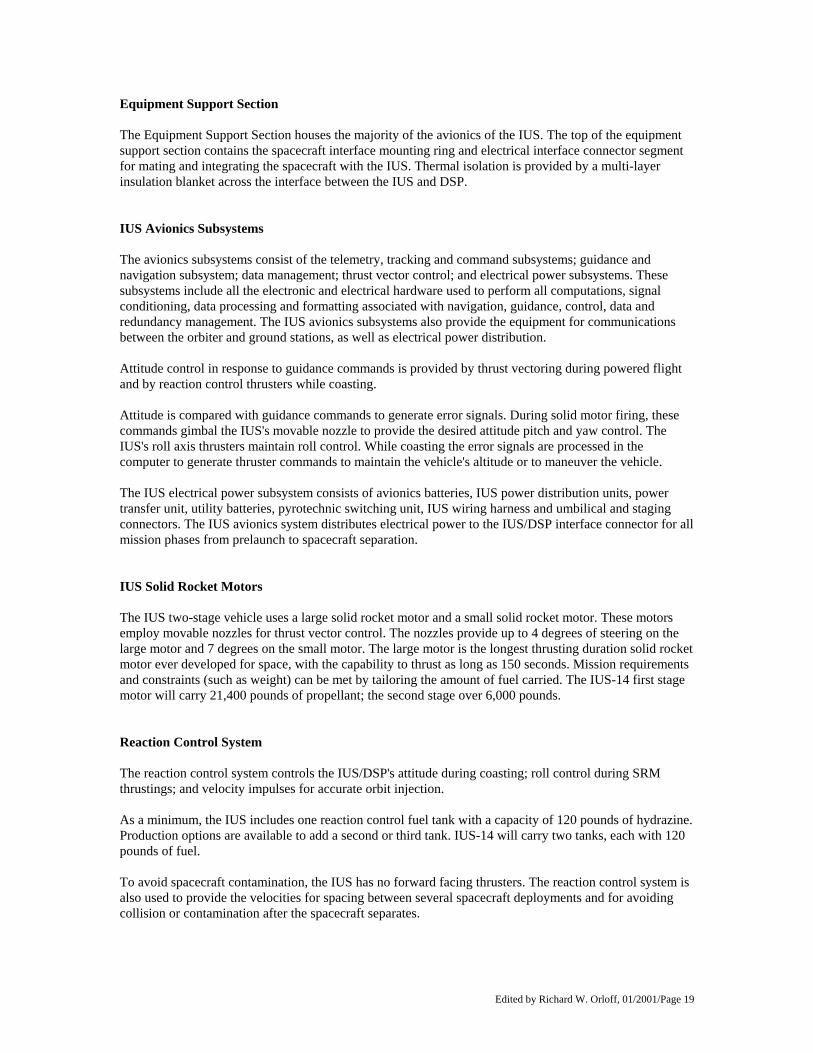
Equipment Support Section The Equipment Support Section houses the majority of the avionics of the IUS. The top of the equipment support section contains the spacecraft interface mounting ring and electrical interface connector segment for mating and integrating the spacecraft with the IUS. Thermal isolation is provided by a multi-layer insulation blanket across the interface between the IUS and DSP. IUS Avionics Subsystems The avionics subsystems consist of the telemetry, tracking and command subsystems; guidance and navigation subsystem; data management; thrust vector control; and electrical power subsystems. These subsystems include all the electronic and electrical hardware used to perform all computations, signal conditioning, data processing and formatting associated with navigation, guidance, control, data and redundancy management. The IUS avionics subsystems also provide the equipment for communications between the orbiter and ground stations, as well as electrical power distribution. Attitude control in response to guidance commands is provided by thrust vectoring during powered flight and by reaction control thrusters while coasting. Attitude is compared with guidance commands to generate error signals. During solid motor firing, these commands gimbal the IUS's movable nozzle to provide the desired attitude pitch and yaw control. The IUS's roll axis thrusters maintain roll control. While coasting the error signals are processed in the computer to generate thruster commands to maintain the vehicle's altitude or to maneuver the vehicle. The IUS electrical power subsystem consists of avionics batteries, IUS power distribution units, power transfer unit, utility batteries, pyrotechnic switching unit, IUS wiring harness and umbilical and staging connectors. The IUS avionics system distributes electrical power to the IUS/DSP interface connector for all mission phases from prelaunch to spacecraft separation. IUS Solid Rocket Motors The IUS two-stage vehicle uses a large solid rocket motor and a small solid rocket motor. These motors employ movable nozzles for thrust vector control. The nozzles provide up to 4 degrees of steering on the large motor and 7 degrees on the small motor. The large motor is the longest thrusting duration solid rocket motor ever developed for space, with the capability to thrust as long as 150 seconds. Mission requirements and constraints (such as weight) can be met by tailoring the amount of fuel carried. The IUS-14 first stage motor will carry 21,400 pounds of propellant; the second stage over 6,000 pounds. Reaction Control System The reaction control system controls the IUS/DSP's attitude during coasting; roll control during SRM thrustings; and velocity impulses for accurate orbit injection. As a minimum, the IUS includes one reaction control fuel tank with a capacity of 120 pounds of hydrazine. Production options are available to add a second or third tank. IUS-14 will carry two tanks, each with 120 pounds of fuel. To avoid spacecraft contamination, the IUS has no forward facing thrusters. The reaction control system is also used to provide the velocities for spacing between several spacecraft deployments and for avoiding collision or contamination after the spacecraft separates.

Edited by Richard W. Orloff, 01/2001/Page 20
IUS-to-Spacecraft Interfaces The DSP spacecraft is physically attached to the IUS at eight attachment points, providing substantial load-carrying capability while minimizing the transfer of heat across the connecting points. Power command and data transmission between the two are provided by several IUS interface connectors. In addition, the IUS provides an insulation blanket comprised of multiple layers of double-aluminized Kapton and polyester net spacers across the IUS/DSP interface. The outer layer of the blanket, facing the DSP spacecraft, is a special Teflon-coated fabric called Beta cloth. The blankets are vented toward and into the IUS cavity, which in turn is vented to the orbiter payload bay. There is no gas flow between the spacecraft and the IUS. The thermal blankets are grounded to the IUS structure to prevent electrostatic charge buildup.

Edited by Richard W. Orloff, 01/2001/Page 21
IUS/DSP DEPLOYMENT AND FLIGHT SEQUENCE After the orbiter payload bay doors are opened in orbit, the orbiter will maintain a preselected attitude to keep the payload within thermal requirement constraints. On-orbit predeployment checkout begins, followed by an IUS command link check and spacecraft communications command check. Orbiter trim maneuver(s) are normally performed at this time. Forward payload restraints are released and the aft frame of the airborne support equipment tilts the IUS/DSP to 29 degrees. This extends the DSP into space just outside the orbiter payload bay, allowing direct communication with Earth during systems checkout. The orbiter is then maneuvered to the deployment attitude. If a problem develops within the spacecraft or IUS, the IUS and its payload can be restowed. Prior to deployment, the spacecraft electrical power source is switched from orbiter power to IUS internal power by the orbiter flight crew. After verifying that the spacecraft is on IUS internal power and that all IUS/DSP predeployment operations have been successfully completed, a GO/NO-GO decision for IUS/DSP deployment is sent to the crew. When the orbiter flight crew is given a GO decision, they activate the pyrotechnics that separate the IUS/DSP umbilical cables. The crew then commands the electromechanical tilt actuator to raise the tilt table to a 58-degree deployment position. The orbiter's RCS thrusters are inhibited and a pyrotechnic separation device is initiated to physically separate the IUS/spacecraft combination from the tilt table. Compressed springs provide the force to jettison the IUS/DSP from the orbiter payload bay at approximately 4.2 inches per second. The deployment normally is performed in the shadow of the orbiter or in Earth eclipse. The tilt table then is lowered to minus 6 degrees after IUS and its spacecraft are deployed. A small orbiter maneuver is made to back away from the IUS/DSP. Approximately 15 minutes after IUS/DSP deployment, the orbiter's engines are ignited to move the orbiter away from the IUS/spacecraft. At this point, the IUS/DSP is controlled by the IUS onboard computers. Approximately 10 minutes after the IUS/DSP is ejected from the orbiter, the IUS onboard computer sends signals used by the IUS to begin mission sequence events. This signal also enables the reaction control system. All subsequent operations are sequenced by the IUS computer, from transfer orbit injection through spacecraft separation and IUS deactivation. After the RCS has been activated, the IUS maneuvers to the required thermal attitude and performs any required spacecraft thermal control maneuvers. At approximately 45 minutes after ejection from the orbiter, the pyrotechnic inhibits for the first solid rocket motor are removed. The belly of the orbiter has been oriented towards the IUS/DSP combination to protect the orbiter windows from the IUS's plume. The IUS recomputes the first ignition time and maneuvers necessary to attain the proper attitude for the first thrusting period. When the proper transfer orbit opportunity is reached, the IUS computer sends the signal to ignite the first stage motor. This is expected at approximately 60 minutes after deployment (L+7 hours, 207 minutes). After firing approximately 146 seconds and prior to reaching the apogee point of its trajectory, the IUS first stage expends its fuel. While coasting, the IUS performs maneuvers needed by the DSP for thermal protection or communications. When this is completed, the IUS first stage and interstage separate from the IUS second stage. Approximately 6 hours, 20 minutes after deployment (at approximately L+12:39) the second stage motor ignites, thrusting about 108 seconds. After burn is complete, the IUS stabilizes the DSP while the solar arrays and two antennas are deployed. The IUS second stage separates and performs a final collision/contamination avoidance maneuver before deactivating.

Edited by Richard W. Orloff, 01/2001/Page 22
TERRA SCOUT TERRA SCOUT is an Earth observation experiment, which will utilize the skills of a trained analyst to perform the observations. The analyst is a payload specialist (PS) who has intensively studied the sites of interest. The PS is experienced in imagery analysis, terrain and aerial observation, and has some formal geology training. The PS will use the Spaceborne Direct-View Optical System (SpaDVOS) to assist him in the site analysis. Each site will have a prepared site packet which includes selected maps and photographs. A number of selected sites have large resolution panels laid out in a grid pattern. The use of these grids will facilitate quantifying the resolution limit from the Shuttle cabin. The primary objective of the TERRA SCOUT experiment is to explore the man/machine interface between skilled technicians and current and advanced sensors.
M88-1 M88-1 is an ongoing series of tri-service experiments designed to asses man's visual and communication capabilities from space. Areas of investigation include dynamic Shuttle tasking, near real-time information relay, and quantification of the astronaut's visual resolution limits. The STS-44 mission will incorporate small aperture, long focal-length optics, and a charge-coupled device (CCD) camera to produce a high-resolution digital image that can be stored, manipulated, and evaluated on-orbit. Pertinent findings will then be communicated via UHF voice to tactical field users seconds after the observation pass is complete. Observation and communication sites include various Army, Navy and Air Force units. Site may be fixed (air fields, port facilities, etc.) or mobile (ships at sea and ground participants). Emphasis is on coordinating observations with ongoing DOD exercises to fully assess the military benefits of a spaceborne observer.
ULTRAVIOLET PLUME INSTRUMENT The Strategic Defense Initiative's Ultraviolet Plume Instrument (UVPI) is a sensor package which collects images of the UV emission from rocket plumes in space and measures the UV backgrounds seen from a space platform. The UVPI is mounted in a satellite currently in low earth orbit called the Low-Power Atmospheric Compensation Experiment (LACE), developed by the Naval Research Laboratory (NRL) and launched February 14, 1990. The Shuttle crew will perform different types of engine burns when within view and range of the LACE satellite. UVPI will collect plume data on orbital maneuvering system (OMS) and primary reaction control system (PRCS) engine burns. The UVPI is mounted to look through an aperture in the Earth- facing end of the LACE satellite. A gimbaled mirror allows the UVPI to look at objects within a 50 degree half-angle cone about nadir. Another mirror mounted on the instrument's door allows observation of stars and the Earth's horizon when the door is partially open. The UVPI has two cameras. The tracker camera has a 1.9 degree by 2.5 degree field of view and is used to acquire and track a target so that the electronic tracker can lock on and bring the target into the smaller field-of-view (0.11 x 0.15 degree) of the plume camera. The tracker camera has a 245 to 450 nanometer passband. The plume camera has four filters which can be selected. The four passbands for the plume camera are:
260 to 280 nanometers 300 to 320 nanometers 220 to 260 nanometers 250 to 345 nanometers
Images can be transmitted from the UVPI and the LACE satellite at either 5 or 30 images per second, depending on the selected size of the image. Emissions observed by the UVPI in wavelengths between 220 and 320 nanometers cannot pass through the Earth's ozone layer, which is found at altitudes between 40 and 80 kilometers. Therefore the 220 to 320 nanometer emission from a rocket firing above 80 kilometers can only by observed by a space-based instrument such as UVPI. Since the Shuttle will be orbiting above the atmosphere, UVPI will have an unencumbered view of the Shuttle plumes.

Edited by Richard W. Orloff, 01/2001/Page 23
Edited by Richard W. Orloff, 01/2001/Page 24
EXTENDED DURATION ORBITER MEDICAL PROJECT A series of medical investigations are included in the STS-44 flight plan to assist in the continuing development of countermeasures to combat adverse effects of space flight. The headward shift of body fluids and slight muscle atrophy that occurs in space causes no problems while astronauts are in space. Researchers are investigating the readaptive processes that occur immediately upon return to Earth's gravity during landing and egress operations. The Extended Duration Orbiter Medical Project, sponsored by the Johnson Space Center's Medical Science Division, will validate countermeasures for longer duration flights. Nine of the 13 Detailed Supplementary Objectives flying on STS-44 support the project. The crew's activities will include electrocardiograph monitoring; measurement of inner eye pressure; assessing orthostatic function, the ability to stand upright upon return to Earth; treadmill exercise; checking gaze stability; and examining endocrine system regulation. Many of the on-orbit findings will be compared with tests done before and after the flight. A large segment of the crew's time will be devoted to the Lower Body Negative Pressure investigation (LBNP). This is the validation of a countermeasure combining rehydration and orthostatic stress for use on longer space flights. Operationally it will be a single application, 4-hour treatment scheduled for the day before landing. The validation process, however, uses a more extensive schedule of LBNP testing. The LBNP unit is a sleeping bag-like device that seals at the waist. Once the crew member is situated in the device, the pressure is gradually decreased, drawing fluids to the lower body much like gravity does when one stands upright on Earth. Crew members also will ingest salt tablets and water during the LBNP treatment. The result of the procedure is expected to be an increased tolerance of standing upright upon return to Earth's gravity. During STS-44, crew members will employ "ramp" and "soak" procedures. The ramp, which lasts 36 minutes, gradually lowers the pressure in the unit by 10 millimeters of mercury, or mmHg, increments to -50 mmHg before recovery. The soak procedure, performed once late in the mission, holds the negative pressure in the unit to -30 mmHg for three hours and 45 minutes. A ramp procedure is performed 24 hours later to determine if the soak improved the subject's orthostatic tolerance. Heart rate and blood pressure measurements are taken during both procedures. LBNP has been used a number of times in the United States space program, first during the Skylab missions. STS-44 will be the second flight of an improved, collapsible, locker-stowed unit. Researchers are refining the LBNP protocol which may be used operationally on future 13- through 16-day missions.

Edited by Richard W. Orloff, 01/2001/Page 25
RADIATION MONITORING EQUIPMENT The Radiation Monitoring Equipment-III measures ionizing radiation exposure to the crew within the orbiter cabin. RME-III measures gamma ray, electron, neutron and proton radiation and calculates in real time exposure in RADS-tissue equivalent. The information is stored in memory modules for post-flight analysis. The hand-held instrument will be stored in a middeck locker during flight except for activation and memory module replacement, done every two days. RME-III will be activated by the crew as soon as possible after reaching orbit and operated throughout the mission. A crew member will enter the correct mission elapsed time upon activation. RME-III is the current configuration, replacing the earlier RME-I and RME-II units. RME-III last flew on STS-31. The experiment has four zinc-air batteries and five AA batteries in each replaceable memory module. RME-III is sponsored by the Department of Defense in cooperation with NASA.
SHUTTLE ACTIVATION MONITOR The Shuttle Activation Monitor (SAM) is designed to measure gamma ray data within the orbiter as a function of time and location. Located in the middeck, the crew will install a foil packet at four locations onboard. A tape recorder and two detector assemblies will then record the information. Each activation of the experiment will last about 12 hours and will record information from a different location of the cabin. SAM is sponsored by the Air Force Space Systems Division, Los Angeles.
COSMIC RADIATION EFFECTS AND ACTIVATION MONITOR The Cosmic Radiation Effects and Activation Monitor (CREAM) experiment is designed to collect data on cosmic ray energy loss spectra, neutron fluxes and induced radioactivity. The data will be collected by active and passive monitors placed at specific locations throughout the orbiter's cabin. CREAM data will be obtained from the same locations that will be used to gather data for the Shuttle Activation Monitor (SAM) experiment in an attempt to correlate data between the two. The active monitor will be used to obtain real-time spectral data, while the passive monitors will obtain data during the entire mission to be analyzed after the flight. The flight hardware has the active cosmic ray monitor, a passive sodium iodide detector, and up to five passive detector packages. All hardware fits in one locker on Discovery's middeck. Once in orbit the payload will be unstowed and operated by the crew. A crewmember will be available at regular intervals to monitor the payload/experiment. CREAM is sponsored by the Department of Defense.

Edited by Richard W. Orloff, 01/2001/Page 26

Edited by Richard W. Orloff, 01/2001/Page 27

Edited by Richard W. Orloff, 01/2001/Page 28

Edited by Richard W. Orloff, 01/2001/Page 29
AIR FORCE MAUI OPTICAL SYSTEM The Air Force Maui Optical System (AMOS) is an electrical- optical facility located on the Hawaiian Island of Maui. The facility tracks the orbiter as it flies over the area and records signatures from thruster firings, water dumps or the phenomena of Shuttleglow, a well-documented glowing effect around the Shuttle caused by the interaction of atomic oxygen with the spacecraft. The information obtained is used to calibrate the infrared and optical sensors at the facility. No hardware onboard the Shuttle is needed for the system.
VFT-1 The objective of the VFT-1 experiment is to measure changes in a number of vision parameters in the vision of subjects exposed to microgravity. The VFT-1 consists of hand-held battery-powered testing device which incorporates a binocular eyepiece and uses controlled illumination to present a variety of visual targets for subject testing. The device measures a number of basic vision performance parameters. Test results data are read on a display and recorded on data sheets.
BIOREACTOR FLOW AND PARTICLE TRAJECTORY Bioreactor Flow and Particle Trajectory in Microgravity is a fluid dynamics experiment aboard STS-44 to validate Earth-based predictions for the action of cell cultures in the NASA-developed Slow-Turning Lateral Vessel (STLV) bioreactor. Ground research efforts in cell culturing are limited because of the inability to suspend cultures in the presence of gravity. Cultures grown by standard methods often are damaged by the suspension processes or, in effect, smother their own development when nutrients are blocked from some cells by others developing around them. Researchers are interested in the benefits of flying a bioreactor in space because of the expected increased capabilities for cell culturing. The STLV bioreactor, developed as a tool for Space Station Freedom, grows cell cultures in a horizontal cylindrical container that slowly rotates, emulating microgravity and keeping the cells continuously suspended while bathing them in nutrients and oxygen. On STS-44, components from the NASA bioreactor will occupy two middeck lockers. Inside the system, beads of varying sizes simulating cell cultures of varying sizes will be rotated in a solution of water and nutrients. The action of the beads will be used to validate the predicted action of cell cultures in microgravity. The results of DSO 316 will be used to refine the system for future flight experiments. Though no cell cultures are currently manifested, plans are for researchers to fly growth experiments on future Shuttle flights. Previous ground-based research has resulted in promising findings in kidney, brain tumor, lung, small intestine and cartilage tissue growth. Such tissue growth could be used in disease or replacement research. The STLV bioreactor is a project of the Johnson Space Center's Medical Sciences Division Biotechnology Program, managed by Dr. Glenn Spaulding.

Edited by Richard W. Orloff, 01/2001/Page 30

Edited by Richard W. Orloff, 01/2001/Page 31
STS-44 CREWMEMBERS
STS044-S-002 -- Official portrait of the STS-44 Atlantis, Orbiter Vehicle (OV) 104, crewmembers includes (left to right-seated) pilot Terence T. Henricks, mission commander Frederick D. Gregory, mission specialist F. Story Musgrave, and (left to right-standing) mission specialist James S. Voss, payload specialist Thomas J. Hennen (United States Army), and mission specialist Mario Runco Jr. A backdrop was created using a double exposure technique and an shuttle observation of the Earth's limb. Also displayed in the background are the Defense Support Program (DSP) satellite (left corner) and the mission insignia. No copyright is asserted for this photograph. If a recognizable person appears in the photo, use for commercial purposes may infringe a right of privacy or publicity. It may not be used to state or imply the endorsement by NASA or by any NASA employee of a commercial product, process or service, or used in any other manner that might mislead. Accordingly, it is requested that if this photograph is used in advertising and other commercial promotion, layout and copy be submitted to NASA prior to release. PHOTO CREDIT: NASA or National Aeronautics and Space Administration.

Edited by Richard W. Orloff, 01/2001/Page 32
BIOGRAPHICAL DATA FREDERICK D. GREGORY, 50, Col., USAF, will serve as commander of STS-44 and will be making his third flight. Gregory, from Washington, DC, was selected as an astronaut in January 1978. Gregory's first space flight was as pilot on STS-51B in April 1985. He next flew as commander of STS-33, a Department of Defense-dedicated shuttle mission in November 1989. Gregory graduated from Anacostia High School, Washington, DC, in 1958, received a bachelor's degree from the United States Air Force Academy in 1964 and a master's degree in information systems from George Washington University in 1977. He has logged more than 288 hours in space and more than 6,500 hours of flying time in more than 50 types of aircraft, including 550 combat missions in Vietnam. TERENCE T. HENRICKS, 39, Col., USAF, will serve as pilot. Selected as an astronaut in July 1986, Henricks considers Woodville, OH, his hometown and will be making his first space flight. He graduated from Woodmore High School in Woodville in 1970; received a bachelor's degree in civil engineering from the U.S. Air Force Academy in 1974, and received a master's degree in public administration from Golden Gate University in 1982. Henricks flew the F-4 in fighter squadrons in England and Iceland. In 1980, he was reassigned to Nellis Air Force Base, Las Vegas. After attending the USAF Test Pilot School in 1983, he remained at Edwards Air Force Base, CA, as an F-16C test pilot and chief of the 57th Fighter Weapons Wing Operating Location until his selection as an astronaut. Henricks has logged more than 3,300 hours flying time in more than 30 different types of aircraft. JAMES S. VOSS, 42, Lt. Col, USA, will serve as mission specialist 1 (MS1). Selected as an astronaut in June 1987, Voss will be making his first space flight and considers Opelika, AL, his hometown. Voss graduated from Opelika High School; received a bachelor's degree in aerospace engineering from Auburn University in 1972; and received a master's degree in aerospace engineering sciences from the University of Colorado in 1974. Voss taught for three years in the Department of Mechanics at the U.S. Military Academy and attended the U.S. Naval Test Pilot School. He was involved in four major flight test projects before being detailed to the Johnson Space Center in November 1984 as a vehicle integration test engineer. At JSC, he supported shuttle and payload testing at the Kennedy Space Center for STS 51-D, 51-F, 61-C and 51-L, and participated in the STS 51-L accident investigation until his selection as an astronaut.

Edited by Richard W. Orloff, 01/2001/Page 33
BIOGRAPHICAL DATA STORY MUSGRAVE, 56, will be mission specialist 2 (MS2). Selected as an astronaut in August 1967, Musgrave considers Lexington, KY, his hometown and will be making his fourth space flight. Musgrave graduated from St. Mark's School, Southborough, MA, in 1953; received a bachelor's degree in mathematics and statistics from Syracuse University in 1958; received a master's degree in operations analysis and computer programming from the University of California at Los Angeles in 1959; received a bachelor's degree in chemistry from Marietta College in 1960; received a doctorate in medicine from Columbia University in 1964; received a master's degree in physiology and biophysics from the University of Kentucky in 1966; and received a master's degree in literature from the University of Houston in 1987. Musgrave flew as a mission specialist on STS-6 in April 1983, on Spacelab-2 in August 1985 and on STS-33 in November 1989. He has logged more than 431 hours in space. MARIO RUNCO Jr., 39, Lt. Comdr., USN, will be mission specialist 3 (MS3). Selected as an astronaut in June 1987, Runco considers Yonkers, NY, his hometown and will be making his first space flight. Runco graduated from Cardinal Hayes High School, Bronx, NY, in 1970; received a bachelor's degree in meteorology and physical oceanography from the City College of New York in 1974; and received a master's degree in meteorology from Rutgers University, New Brunswick, NJ, in 1976. Runco worked as a research hydrologist for the U.S. Geological Survey in New York, and, in 1977, he became a New Jersey State Trooper until entering the Navy in June 1978. He was assigned to the Naval Environmental Prediction Research Facility in Monterey, CA, as a research meteorologist. He later commanded or served on several meteorological and oceanographic surveys and research assignments aboard various Naval vessels. THOMAS J. HENNEN, 39, CWO-3, USA, will serve as payload specialist (PS). Hennen considers Columbus, OH, his hometown and will be making his first space flight. He graduated from Groveport-Madison High School in Groveport, OH, in 1970; attended Urbana College in Urbana, OH, from 1970-1972; and completed numerous military courses of instruction. Hennen has more than 18 years of Army experience in acquisitions management and as an operational imagery analyst. He has been assigned to the 163rd Military Intelligence Battalion, the 203rd Military Intelligence Detachment and the 2nd Military Intelligence Battalion. From 1981-1986, Hennen was stationed in Fort Huachuca, Ariz., and was involved in the development of U.S. Army imagery interpretation training and applications courses.

Edited by Richard W. Orloff, 01/2001/Page 34
STS-44 MISSION MANAGEMENT - NASA NASA HEADQUARTERS, WASHINGTON, DC Richard H. Truly NASA Administrator J. R. Thompson Deputy Administrator Dr. William Lenoir Associate Administrator, Office of Space Flight Robert L. Crippen Director, Space Shuttle Leonard S. Nicholson Deputy Director, Space Shuttle (Program) Brewster H. Shaw Deputy Director, Space Shuttle (Operations) George A. Rodney Associate Administrator for Safety and Mission Quality James H. Ehl Deputy Associate Administrator for Safety and Mission Quality Richard U. Perry Director, Programs Assurance Division KENNEDY SPACE CENTER, FL Forrest S. McCartney Director James A. Thomas Deputy Director Robert B. Sieck Launch Director George T. Sasseen Shuttle Engineering Director John T. Conway Director, Payload Management and Operations Joanne H. Morgan Director, Payload Project Management Conrad Nagel Atlantis Flow Director MARSHALL SPACE FLIGHT CENTER, HUNTSVILLE, AL Thomas J. Lee Director Dr. J. Wayne Littles Deputy Director G. Porter Bridwell Manager, Shuttle Projects Office Dr. George F. McDonough Director, Science and Engineering Alexander A. McCool Director, Safety and Mission Assurance James N. Strickland Acting Manager, Space Shuttle Main Engine Project Victor Keith Henson Manager, Solid Rocket Motor Project Cary H. Rutland Manager, Solid Rocket Booster Project Gerald C. Ladner Manager, External Tank Project JOHNSON SPACE CENTER, HOUSTON, TX Aaron Cohen Director Paul J. Weitz Deputy Director Daniel Germany Manager, Orbiter and GFE Projects Richard Covey Acting Director, Flight Crew Operations Eugene F. Kranz Director, Mission Operations Henry O. Pohl Director, Engineering Charles S. Harlan Director, Safety, Reliability and Quality Assurance

Edited by Richard W. Orloff, 01/2001/Page 35
STENNIS SPACE CENTER, BAY ST. LOUIS, MS Roy S. Estess, Director Gerald W. Smith Deputy Director J. Harry Guin Director, Propulsion Test Operations AMES-DRYDEN FLIGHT RESEARCH FACILITY, EDWARDS, CA Kenneth J. Szalai Director T. G. Ayers Deputy Director James R. Phelps Chief, Shuttle Support Office
STS-44 MISSION MANAGEMENT - DOD Mission Director Col. John R. Kidd, Program Director, Defense Support Program Deputy Mission Director Col. John E. Armstrong, Program Manager, Space Test and Transportation System Program Office IUS Program Management Col. Norman H. Buchanan, Program Director, Upper Stages Program Office Mission Director Representatives Col. Edward R. Dietz Deputy Program Director, Defense Support Program Major Michael W. Booen Director, Space Systems Mission Director Support Team Capt. Linda R. Cole, Mission Manager, SSD/MJSO Capt. Gregory D. Moxley, DSP Integration Manager, SSD/MJSO Capt. Samuel J. Domino, MD Action Officer, JSC/OL-AW Lt. Anthony F. Papatyi, IUS Integration Manager, SSD/CLUI Air Force Test Director Maj. John Traxler, 6555 ASTG CSTC Flight Directors Capt. Rick Kellogg, Ascent, CSTC/VOS Capt. Frank Alexa (Lead), Deploy Phase, CSTC/VOS Capt. Bill Moriarity, Transfer Orbit, CSTC/VOS Spacecraft Flight Directors Capt. Rich Edmonds (Lead), Deploy Phase, SSD/MJSO Capt. Kathy Hays, Transfer Orbit, SSD/MJSO Secondary Payload Operations Manager

Edited by Richard W. Orloff, 01/2001/Page 36
SHUTTLE FLIGHTS AS OF NOVEMBER 1991 43 TOTAL FLIGHTS OF THE SHUTTLE SYSTEM -- 18 SINCE RETURN TO FLIGHT
STS-48 09/12/91 - 09/18/91
STS-39 04/28/91 - 05/06/91
STS-40 06/05/91 - 06/14/91
STS-41 10/06/90 - 10/10/90
STS-35 12/02/90 - 12/10/90
STS-51L 01/28/86
STS-31 04/24/90 - 04/29/90
STS-32 01/09/90 - 01/20/90
STS-61A 10/30/85 - 11/06/85
STS-33 11/22/89 - 11/27/89
STS-43 08/02/91 - 08/11/91
STS-28 08/08/89 - 08/13/89
STS-51F 07/29/85 - 08/06/85
STS-29 03/13/89 - 03/18/89
STS-37 04/05/91 - 04/11/91
STS-61C 01/12/86 - 01/18/86
STS-51B 04/29/85 - 05/06/85
STS-26 09/29/88 - 10/03/88
STS-38 11/15/90 - 11/20/90
STS-9 11/28/83 - 12/08/83
STS-41G 10/05/84 - 10/13/84
STS-51-I 08/27/85 - 09/03/85
STS-36 02/28/90 - 03/04/90
STS-5 11/11/82 - 11/16/82
STS-41C 04/06/84 - 04/13/84
STS-51G 06/17/85 - 06/24/85
STS-34 10/18/89 - 10/23/89
STS-4 06/27/82 - 07/04/82
STS-41B 02/03/84 - 02/11/84
STS-51D 04/12/85 - 04/19/85
STS-30 05/04/89 - 05/08/89
STS-3 03/22/82 - 03/30/82
STS-8 08/30/83 - 09/05/83
STS-51C 01/24/85 - 01/27/85
STS-27 12/02/88 - 12/06/88
STS-2 11/12/81 - 11/14/81
STS-7 06/18/83 - 06/24/83
STS-51A 11/08/84 - 11/16/84
STS-61B 11/26/85 - 12/03/85
STS-1 04/12/81 - 04/14/81
STS-6 04/04/83 - 04/09/83
STS-41D 08/30/84 - 09/05/84
STS-51J 10/03/85 - 10/07/85
OV-102
Columbia (11 flights)
OV-099 Challenger (10 flights)
OV-103 Discovery (13 flights)
OV-104 Atlantis
(9 flights)