Embed Size (px)
Citation preview
ORIGINAL ARTICLE
Space-borne BDS receiver for LING QIAO satellite: design,implementation and preliminary in-orbit experiment results
Xi Chen1 • Sihao Zhao2 • Menglu Wang1 • Mingquan Lu2
Received: 25 June 2015 / Accepted: 8 October 2015 / Published online: 19 October 2015
� The Author(s) 2015. This article is published with open access at Springerlink.com
Abstract Known as China’s first low earth orbit (LEO)
mobile communication experimental satellite, the LING
QIAO satellite was launched on September 4, 2014. In
addition to the two global positioning system (GPS)
receivers on board, which are the main navigation receivers
supporting the synchronized LEO communication payload
and other systems that require navigation input, a BeiDou
navigation system (BDS) receiver is also installed on board
as an experimental payload. We present the system design
and preliminary in-orbit experiment results of the BDS
receiver of the LING QIAO satellite. The results show that:
(1) The root-mean-square positioning error of the BDS
receiver is 13 m, while the GPS error is 1 m; (2) the in-
orbit traced service area of BDS is from 55�S to 55�N,
70�E to 150�E, which matches the official announced
service area; (3) for industrial-level chips and devices of
the BDS payload which are vulnerable to space radiations,
the single-event effect monitoring and combating mea-
sures, as presented in this work, have been effective for
LING QIAO satellite.
Keywords Space-borne BDS receiver � LEO
communication satellite � System design � In-orbit
performance
Introduction
Recently, there witnessed a new wave of satellite com-
munication constellation plans and constructions. Iridium
Communications Inc. is developing Iridium NEXT satel-
lites to refresh its aging first-generation mobile messaging
fleet with the first satellite engineering model completed in
August, 2014. The O3b satellite constellation, which is
designed for telecommunications and data backhaul from
remote locations, has been put into services with eight
satellites in 2014 (Blumenthal 2013). China’s first low
earth orbit (LEO) communication experimental satellite,
named LING QIAO (NORAD ID: 40136, International
code: 2014-051A), was launched on September 4, 2014,
with an announcement of 4 satellites to follow. The work
was done jointly by Space Center, Tsinghua University and
XinWei Telecom Group, China (Jin et al. 2015).
Until now, the LING QIAO satellite has been in oper-
ation in space for more than half a year. Unlike Iridium or
GlobalStar satellites, which adopt a satellite-fixed mobile
communication system, LING QIAO adopted a user-fixed
mobile communication system in which wireless commu-
nication beams are real-time-adjusted and directed to the
users. Such an adaptive communication system maximizes
the usage of the limited wireless spectrum; however, it also
highly relies on modern global navigation satellite systems
(GNSS) to obtain a precise space and time reference under
rapid relative movement between LIANG QIAO and the
users. The challenges therein for such GNSS receivers are
achieving robust positioning and precise timing under a
space vehicle movement with a speed about 7.5 km/s at
800 km altitude. In order to meet such requirements, the
LING QIAO satellite is equipped with two global posi-
tioning system (GPS) receivers on board, which are the
main navigation receivers supporting the synchronized
& Sihao Zhao
1 Space Center, Tsinghua University, Beijing, China
2 Department of Electronic Engineering, Tsinghua University,
Beijing 100084, China
123
GPS Solut (2016) 20:837–847
DOI 10.1007/s10291-015-0493-x
LEO communication payload and other systems that
require navigation input. A BeiDou navigation system
(BDS) receiver is also installed on board as an experi-
mental payload and a backup for GPS receivers.
In fact, space-borne GNSS receivers have become a
standard component of LEO satellites. Depending on the
requirements of different space missions, they have been
used for various purposes. At the early stage, they were
used for real-time onboard orbit determination (Bertiger
et al. 1998; Stieglitz 1999). Recently, an onboard space-
borne GPS receiver can achieve much better orbit deter-
mination precision than methods based on ground obser-
vations. For example, within the PROBA-2 microsatellite
mission, a miniaturized single-frequency GPS receiver
based on commercial-on-the-shelf (COTS) technology was
employed for onboard navigation with a real-time root-
mean-square (RMS) error of 1 m (Montenbruck et al.
2012). In some scientific space missions, multi-frequency
receivers are adopted to collect in-orbit measurements, and
off-line orbit determination algorithms are crafted to
achieve centimeter-level precise orbit determination. In
TerraSAR-X missions, the precise orbit determination
based on GPS achieved an accuracy better than 10 cm from
the internal and external orbit assessment (Yoon et al.
2009). For the gravity recovery and climate experiment
(GRACE) satellites, GPS data are open to the public for
precise orbit determination research purposes. Research
has reported centimeter-level results with GRACE GPS
data. For example, Kang et al. (2006) achieved an accuracy
of about 2 cm in each axis component. Space-borne GNSS
receivers not only can be used for orbit determination of
LEO satellites, but also can be used for determining the
orbits of satellites whose altitudes are higher than that of
GNSS (Garrison et al. 2002). NASA Goddard Space Flight
Center (GSFC) had developed a new space-borne GPS
receiver, called Navigator, which can operate effectively in
the full range of earth orbiting missions ranging from LEO
to GEO and beyond. The Navigator employs special signal
processing algorithms in radiation-hardened hardware that
enables very fast signal acquisition capabilities and
improved sensitivity, i.e., a 10-dB improvement over pre-
vious space-based GPS receivers whose sensitivity is
around -130 dBm (Winternitz et al. 2009). Space-borne
GNSS receivers can also be used as attitude sensors in
some space mission (Pendergrass and Treder 2000; Duncan
et al. 2010). Due to limited baseline length, the achieved
precisions are at 1� level (Abbas et al. 2013). In recent
years, space-borne GNSS receivers are also being used for
remote sensing. For example, GNSS-based radio occulta-
tion has become an important way of sounding the atmo-
sphere and profiling the ionosphere of the earth (Chiu et al.
2008; Norman et al. 2012; Li et al. 2014). Space-borne
GNSS reflectometry (GNSS-R) has also achieved rapid
development nowadays (Fazliani et al. 2012; Park et al.
2012; Lowe et al. 2014; Pascual et al. 2014). Although the
future of space-borne GNSS-R is promising, there are still
much work to be done for both GNSS-R receiver design
and data post-processing.
Whereas GPS is the most mature satellite navigation
system, the BDS is a new comer to the modern GNSS club.
BDS has been put into regional service since December
2012. The Interface Control Document for Open Service
Signal (CSNO 2013b) and the Open Service Performance
Standard (CSNO 2013a) have been released. The current
BDS space segment consists of five geostationary earth orbit
(GEO) satellites, five inclined geosynchronous orbit (IGSO)
satellites and five medium earth orbit (MEO) satellites. The
GEO satellites are operating in an orbit at altitude of
35,786 km and positioned at 58.75�E, 80E, 110.5�E, 140�Eand 160�E, respectively. The IGSO satellites are operating in
an orbit at altitude of 35,786 km and an inclination of 55 to
the equator. The right ascension difference in the ascending
nodes is 120� between IGSO orbital planes. The longitude of
the intersection point for three of the IGSOs is 118�E, and
that for the other two is 95�E. The MEO satellites are
operating in orbit at altitude of 21,528 km and inclination of
55� to the equator. The satellite recursion period is 13 rota-
tions within 7 days. The phase is selected from the Walker
24/3/1 constellation, and the right ascension of ascending
node in the first orbital plane is 0�. The four MEO satellites
are in the 7th and 8th phases of the first orbital plane, and in
the 3rd and 4th phases of the second orbital plane, respec-
tively. Until now, BDS is still a regional navigation system
that covers most of the Asia–pacific region (CSNO 2013a, b).
Since the beginning of the regional service of BDS,
research results on BDS receivers, signals and perfor-
mances are increasingly reported. However, most of them
are ground based, and very few discuss its applications for
space users. In this work, we present the system design of
the BDS receiver as well as the GPS receiver and then the
preliminary in-orbit experiment results of the BDS receiver
of LING QIAO satellite. The results show that: (1) The
RMS positioning error of the BDS receiver is 13 m, while
the GPS error is 1 m; (2) the in-orbit traced service area of
BDS is from 55�S to 55�N, 70�E to 150�E, which matches
the official announced service area; (3) the single-event
effect monitoring and combating measures designed for the
industrial-level chips of the receiver, as presented in this
work, have been effective on LING QIAO satellite.
The navigation subsystem of LING QIAO
The navigation subsystem of LING QIAO provides precise
time, position and velocity for other subsystems including
the space mobile communication payload of the satellite,
838 GPS Solut (2016) 20:837–847
123
which is one of the most important subsystems of the
satellite. In this section, we present system aspects of the
LING QIAO navigation subsystem, including its top-level
design, hardware system, antenna characteristics, RF path
loss and signal processing flow.
Top-level design
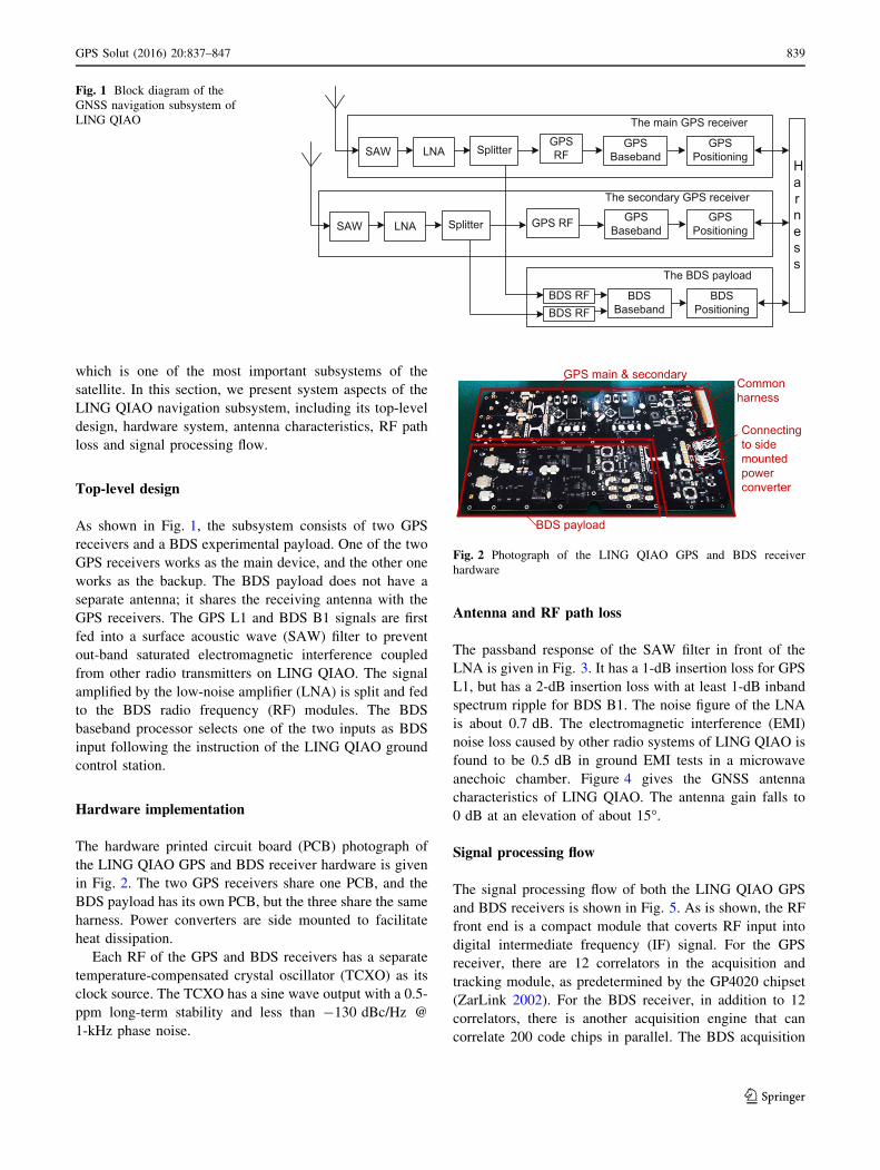
As shown in Fig. 1, the subsystem consists of two GPS
receivers and a BDS experimental payload. One of the two
GPS receivers works as the main device, and the other one
works as the backup. The BDS payload does not have a
separate antenna; it shares the receiving antenna with the
GPS receivers. The GPS L1 and BDS B1 signals are first
fed into a surface acoustic wave (SAW) filter to prevent
out-band saturated electromagnetic interference coupled
from other radio transmitters on LING QIAO. The signal
amplified by the low-noise amplifier (LNA) is split and fed
to the BDS radio frequency (RF) modules. The BDS
baseband processor selects one of the two inputs as BDS
input following the instruction of the LING QIAO ground
control station.
Hardware implementation
The hardware printed circuit board (PCB) photograph of
the LING QIAO GPS and BDS receiver hardware is given
in Fig. 2. The two GPS receivers share one PCB, and the
BDS payload has its own PCB, but the three share the same
harness. Power converters are side mounted to facilitate
heat dissipation.
Each RF of the GPS and BDS receivers has a separate
temperature-compensated crystal oscillator (TCXO) as its
clock source. The TCXO has a sine wave output with a 0.5-
ppm long-term stability and less than -130 dBc/Hz @
1-kHz phase noise.
Antenna and RF path loss
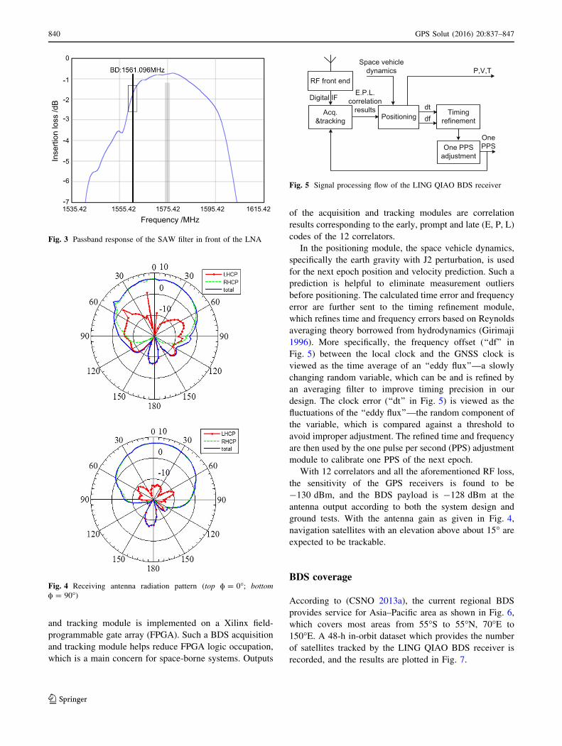
The passband response of the SAW filter in front of the
LNA is given in Fig. 3. It has a 1-dB insertion loss for GPS
L1, but has a 2-dB insertion loss with at least 1-dB inband
spectrum ripple for BDS B1. The noise figure of the LNA
is about 0.7 dB. The electromagnetic interference (EMI)
noise loss caused by other radio systems of LING QIAO is
found to be 0.5 dB in ground EMI tests in a microwave
anechoic chamber. Figure 4 gives the GNSS antenna
characteristics of LING QIAO. The antenna gain falls to
0 dB at an elevation of about 15�.
Signal processing flow
The signal processing flow of both the LING QIAO GPS
and BDS receivers is shown in Fig. 5. As is shown, the RF
front end is a compact module that coverts RF input into
digital intermediate frequency (IF) signal. For the GPS
receiver, there are 12 correlators in the acquisition and
tracking module, as predetermined by the GP4020 chipset
(ZarLink 2002). For the BDS receiver, in addition to 12
correlators, there is another acquisition engine that can
correlate 200 code chips in parallel. The BDS acquisition
SAW LNA SplitterGPS RF
GPS Baseband
GPS Positioning
SAW LNA Splitter GPS RF GPS Baseband
GPS Positioning
BDS RF BDS Baseband
BDS Positioning
The main GPS receiver
The secondary GPS receiver
The BDS payload
Harness
BDS RF
Fig. 1 Block diagram of the
GNSS navigation subsystem of
LING QIAO
GPS main & secondary
Connectingto side mounted power converter
Commonharness
BDS payload
Fig. 2 Photograph of the LING QIAO GPS and BDS receiver
hardware
GPS Solut (2016) 20:837–847 839
123
and tracking module is implemented on a Xilinx field-
programmable gate array (FPGA). Such a BDS acquisition
and tracking module helps reduce FPGA logic occupation,
which is a main concern for space-borne systems. Outputs
of the acquisition and tracking modules are correlation
results corresponding to the early, prompt and late (E, P, L)
codes of the 12 correlators.
In the positioning module, the space vehicle dynamics,
specifically the earth gravity with J2 perturbation, is used
for the next epoch position and velocity prediction. Such a
prediction is helpful to eliminate measurement outliers
before positioning. The calculated time error and frequency
error are further sent to the timing refinement module,
which refines time and frequency errors based on Reynolds
averaging theory borrowed from hydrodynamics (Girimaji
1996). More specifically, the frequency offset (‘‘df’’ in
Fig. 5) between the local clock and the GNSS clock is
viewed as the time average of an ‘‘eddy flux’’—a slowly
changing random variable, which can be and is refined by
an averaging filter to improve timing precision in our
design. The clock error (‘‘dt’’ in Fig. 5) is viewed as the
fluctuations of the ‘‘eddy flux’’—the random component of
the variable, which is compared against a threshold to
avoid improper adjustment. The refined time and frequency
are then used by the one pulse per second (PPS) adjustment
module to calibrate one PPS of the next epoch.
With 12 correlators and all the aforementioned RF loss,
the sensitivity of the GPS receivers is found to be
-130 dBm, and the BDS payload is -128 dBm at the
antenna output according to both the system design and
ground tests. With the antenna gain as given in Fig. 4,
navigation satellites with an elevation above about 15� are
expected to be trackable.
BDS coverage
According to (CSNO 2013a), the current regional BDS
provides service for Asia–Pacific area as shown in Fig. 6,
which covers most areas from 55�S to 55�N, 70�E to
150�E. A 48-h in-orbit dataset which provides the number
of satellites tracked by the LING QIAO BDS receiver is
recorded, and the results are plotted in Fig. 7.
0
-1
-2
-3
-4
-5
-6
-71535.42 1555.42 1575.42 1595.42 1615.42
Frequency /MHz
Inse
rtion
loss
/dB
Fig. 3 Passband response of the SAW filter in front of the LNA
Fig. 4 Receiving antenna radiation pattern (top a = 0�; bottom
a = 90�)
Fig. 5 Signal processing flow of the LING QIAO BDS receiver
840 GPS Solut (2016) 20:837–847
123
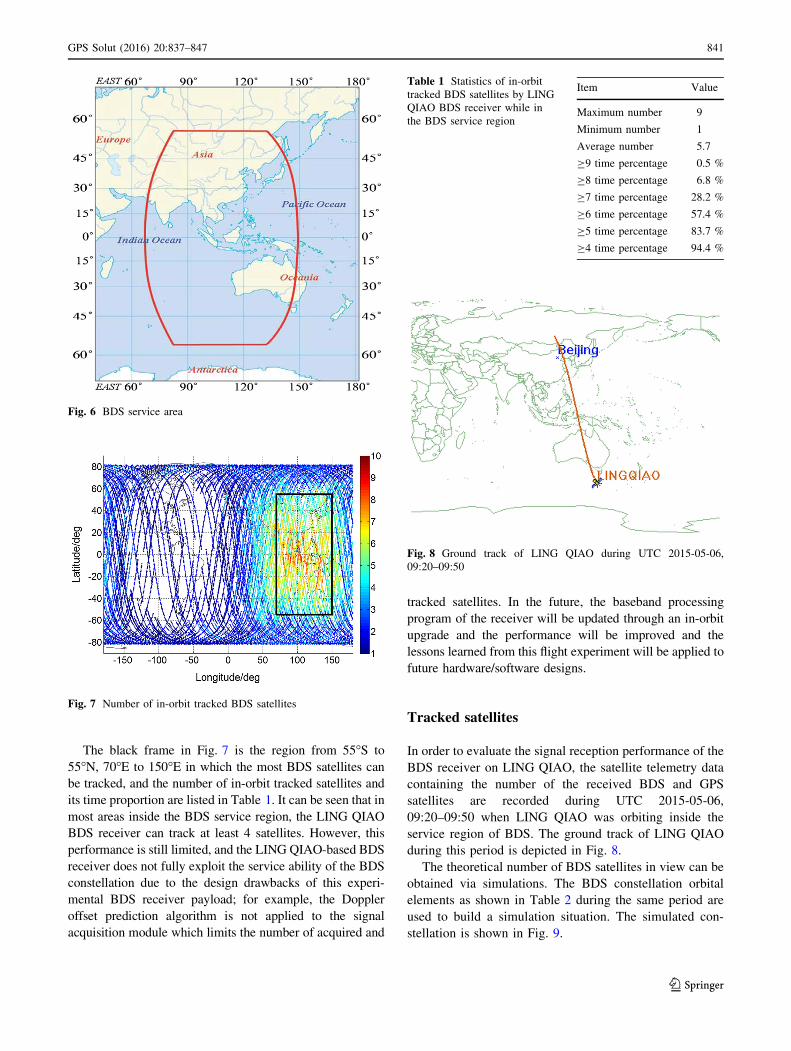
The black frame in Fig. 7 is the region from 55�S to
55�N, 70�E to 150�E in which the most BDS satellites can
be tracked, and the number of in-orbit tracked satellites and
its time proportion are listed in Table 1. It can be seen that in
most areas inside the BDS service region, the LING QIAO
BDS receiver can track at least 4 satellites. However, this
performance is still limited, and the LING QIAO-based BDS
receiver does not fully exploit the service ability of the BDS
constellation due to the design drawbacks of this experi-
mental BDS receiver payload; for example, the Doppler
offset prediction algorithm is not applied to the signal
acquisition module which limits the number of acquired and
tracked satellites. In the future, the baseband processing
program of the receiver will be updated through an in-orbit
upgrade and the performance will be improved and the
lessons learned from this flight experiment will be applied to
future hardware/software designs.
Tracked satellites
In order to evaluate the signal reception performance of the
BDS receiver on LING QIAO, the satellite telemetry data
containing the number of the received BDS and GPS
satellites are recorded during UTC 2015-05-06,
09:20–09:50 when LING QIAO was orbiting inside the
service region of BDS. The ground track of LING QIAO
during this period is depicted in Fig. 8.
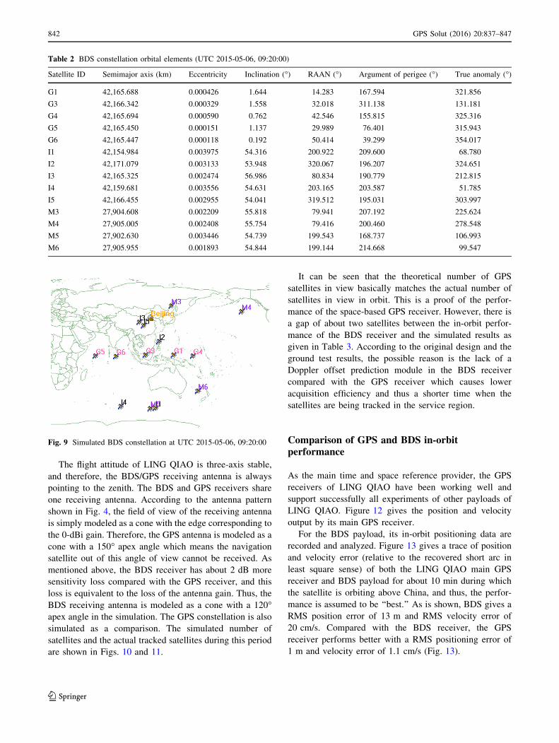
The theoretical number of BDS satellites in view can be
obtained via simulations. The BDS constellation orbital
elements as shown in Table 2 during the same period are
used to build a simulation situation. The simulated con-
stellation is shown in Fig. 9.
Fig. 6 BDS service area
Fig. 7 Number of in-orbit tracked BDS satellites
Table 1 Statistics of in-orbit
tracked BDS satellites by LING
QIAO BDS receiver while in
the BDS service region
Item Value
Maximum number 9
Minimum number 1
Average number 5.7
C9 time percentage 0.5 %
C8 time percentage 6.8 %
C7 time percentage 28.2 %
C6 time percentage 57.4 %
C5 time percentage 83.7 %
C4 time percentage 94.4 %
Fig. 8 Ground track of LING QIAO during UTC 2015-05-06,
09:20–09:50
GPS Solut (2016) 20:837–847 841
123
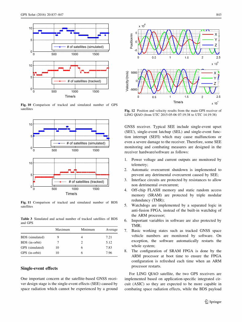
The flight attitude of LING QIAO is three-axis stable,
and therefore, the BDS/GPS receiving antenna is always
pointing to the zenith. The BDS and GPS receivers share
one receiving antenna. According to the antenna pattern
shown in Fig. 4, the field of view of the receiving antenna
is simply modeled as a cone with the edge corresponding to
the 0-dBi gain. Therefore, the GPS antenna is modeled as a
cone with a 150� apex angle which means the navigation
satellite out of this angle of view cannot be received. As
mentioned above, the BDS receiver has about 2 dB more
sensitivity loss compared with the GPS receiver, and this
loss is equivalent to the loss of the antenna gain. Thus, the
BDS receiving antenna is modeled as a cone with a 120�apex angle in the simulation. The GPS constellation is also
simulated as a comparison. The simulated number of
satellites and the actual tracked satellites during this period
are shown in Figs. 10 and 11.
It can be seen that the theoretical number of GPS
satellites in view basically matches the actual number of
satellites in view in orbit. This is a proof of the perfor-
mance of the space-based GPS receiver. However, there is
a gap of about two satellites between the in-orbit perfor-
mance of the BDS receiver and the simulated results as
given in Table 3. According to the original design and the
ground test results, the possible reason is the lack of a
Doppler offset prediction module in the BDS receiver
compared with the GPS receiver which causes lower
acquisition efficiency and thus a shorter time when the
satellites are being tracked in the service region.
Comparison of GPS and BDS in-orbitperformance
As the main time and space reference provider, the GPS
receivers of LING QIAO have been working well and
support successfully all experiments of other payloads of
LING QIAO. Figure 12 gives the position and velocity
output by its main GPS receiver.
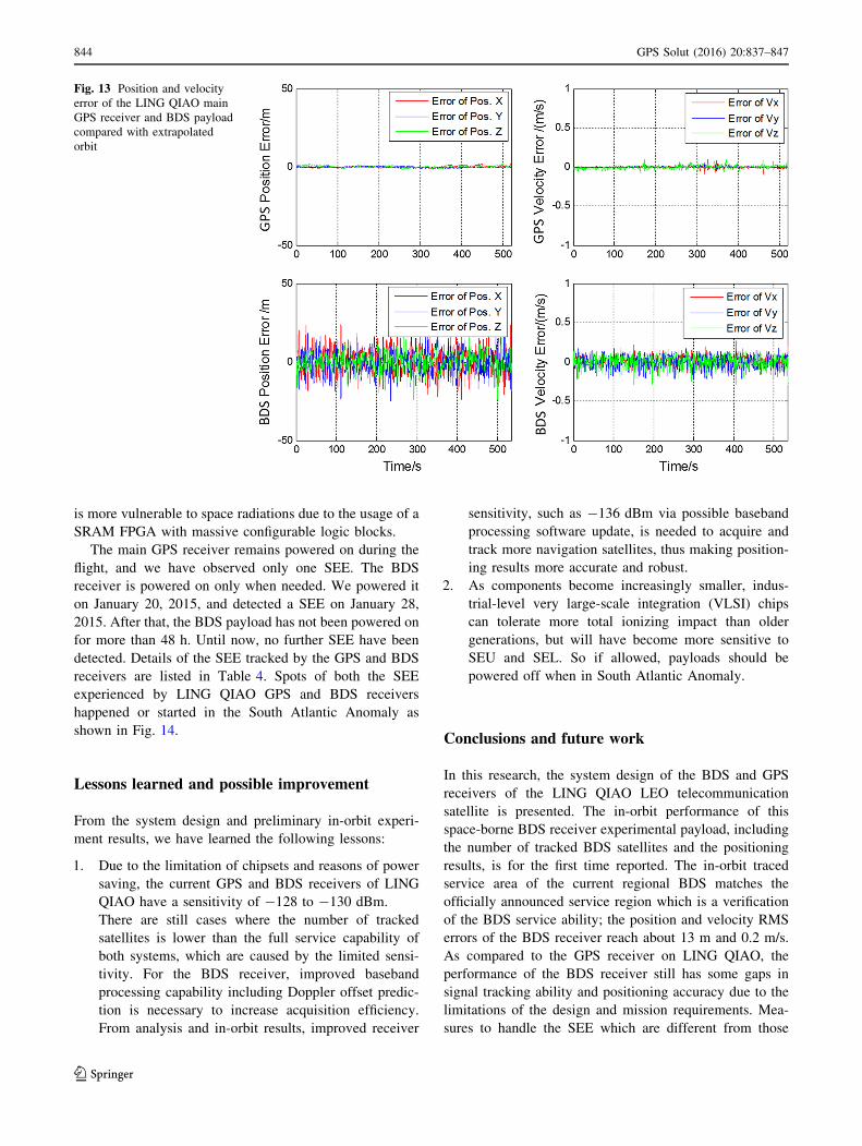
For the BDS payload, its in-orbit positioning data are
recorded and analyzed. Figure 13 gives a trace of position
and velocity error (relative to the recovered short arc in
least square sense) of both the LING QIAO main GPS
receiver and BDS payload for about 10 min during which
the satellite is orbiting above China, and thus, the perfor-
mance is assumed to be ‘‘best.’’ As is shown, BDS gives a
RMS position error of 13 m and RMS velocity error of
20 cm/s. Compared with the BDS receiver, the GPS
receiver performs better with a RMS positioning error of
1 m and velocity error of 1.1 cm/s (Fig. 13).
Table 2 BDS constellation orbital elements (UTC 2015-05-06, 09:20:00)
Satellite ID Semimajor axis (km) Eccentricity Inclination (�) RAAN (�) Argument of perigee (�) True anomaly (�)
G1 42,165.688 0.000426 1.644 14.283 167.594 321.856
G3 42,166.342 0.000329 1.558 32.018 311.138 131.181
G4 42,165.694 0.000590 0.762 42.546 155.815 325.316
G5 42,165.450 0.000151 1.137 29.989 76.401 315.943
G6 42,165.447 0.000118 0.192 50.414 39.299 354.017
I1 42,154.984 0.003975 54.316 200.922 209.600 68.780
I2 42,171.079 0.003133 53.948 320.067 196.207 324.651
I3 42,165.325 0.002474 56.986 80.834 190.779 212.815
I4 42,159.681 0.003556 54.631 203.165 203.587 51.785
I5 42,166.455 0.002955 54.041 319.512 195.031 303.997
M3 27,904.608 0.002209 55.818 79.941 207.192 225.624
M4 27,905.005 0.002408 55.754 79.416 200.460 278.548
M5 27,902.630 0.003446 54.739 199.543 168.737 106.993
M6 27,905.955 0.001893 54.844 199.144 214.668 99.547
Fig. 9 Simulated BDS constellation at UTC 2015-05-06, 09:20:00
842 GPS Solut (2016) 20:837–847
123
Single-event effects
One important concern at the satellite-based GNSS recei-
ver design stage is the single-event effects (SEE) caused by
space radiation which cannot be experienced by a ground
GNSS receiver. Typical SEE include single-event upset
(SEU), single-event latchup (SEL) and single-event func-
tion interrupt (SEFI) which may cause malfunctions or
even a severe damage to the receiver. Therefore, some SEE
monitoring and combating measures are designed in the
receiver hardware/software as follows:
1. Power voltage and current outputs are monitored by
telemetry;
2. Automatic overcurrent shutdown is implemented to
prevent any detrimental overcurrent caused by SEE;
3. Interface circuits are protected by resistances to allow
non detrimental overcurrent;
4. Off-chip FLASH memory and static random access
memory (SRAM) are protected by triple modular
redundancy (TMR);
5. Watchdogs are implemented by a separated logic in
anti-fusion FPGA, instead of the built-in watchdog of
the ARM processor;
6. Important variables in software are also protected by
TMR;
7. Basic working states such as tracked GNSS space
vehicle numbers are monitored by software. On
exception, the software automatically restarts the
whole system;
8. The configuration of SRAM FPGA is done by the
ARM processor at boot time to ensure the FPGA
configuration is refreshed each time when an ARM
processor restarts.
For LING QIAO satellite, the two GPS receivers are
implemented based on application-specific integrated cir-
cuit (ASIC) so they are expected to be more capable in
combating space radiation effects, while the BDS payload
0 500 1000 15000
5
10
# of satellites (simulated)
0 500 1000 15000
5
10
Time/s
# of satellites (tracked)
Fig. 10 Comparison of tracked and simulated number of GPS
satellites
0 500 1000 15000
5
10
# of satellites (simulated)
0 500 1000 15000
5
10
Time/s
# of satellites (tracked)
Fig. 11 Comparison of tracked and simulated number of BDS
satellites
Table 3 Simulated and actual number of tracked satellites of BDS
and GPS
Maximum Minimum Average
BDS (simulated) 9 4 7.21
BDS (in-orbit) 7 2 5.12
GPS (simulated) 10 6 7.83
GPS (in-orbit) 10 6 7.96
Fig. 12 Position and velocity results from the main GPS receiver of
LING QIAO (from UTC 2015-05-06 07:19:38 to UTC 14:19:38)
GPS Solut (2016) 20:837–847 843
123
is more vulnerable to space radiations due to the usage of a
SRAM FPGA with massive configurable logic blocks.
The main GPS receiver remains powered on during the
flight, and we have observed only one SEE. The BDS
receiver is powered on only when needed. We powered it
on January 20, 2015, and detected a SEE on January 28,
2015. After that, the BDS payload has not been powered on
for more than 48 h. Until now, no further SEE have been
detected. Details of the SEE tracked by the GPS and BDS
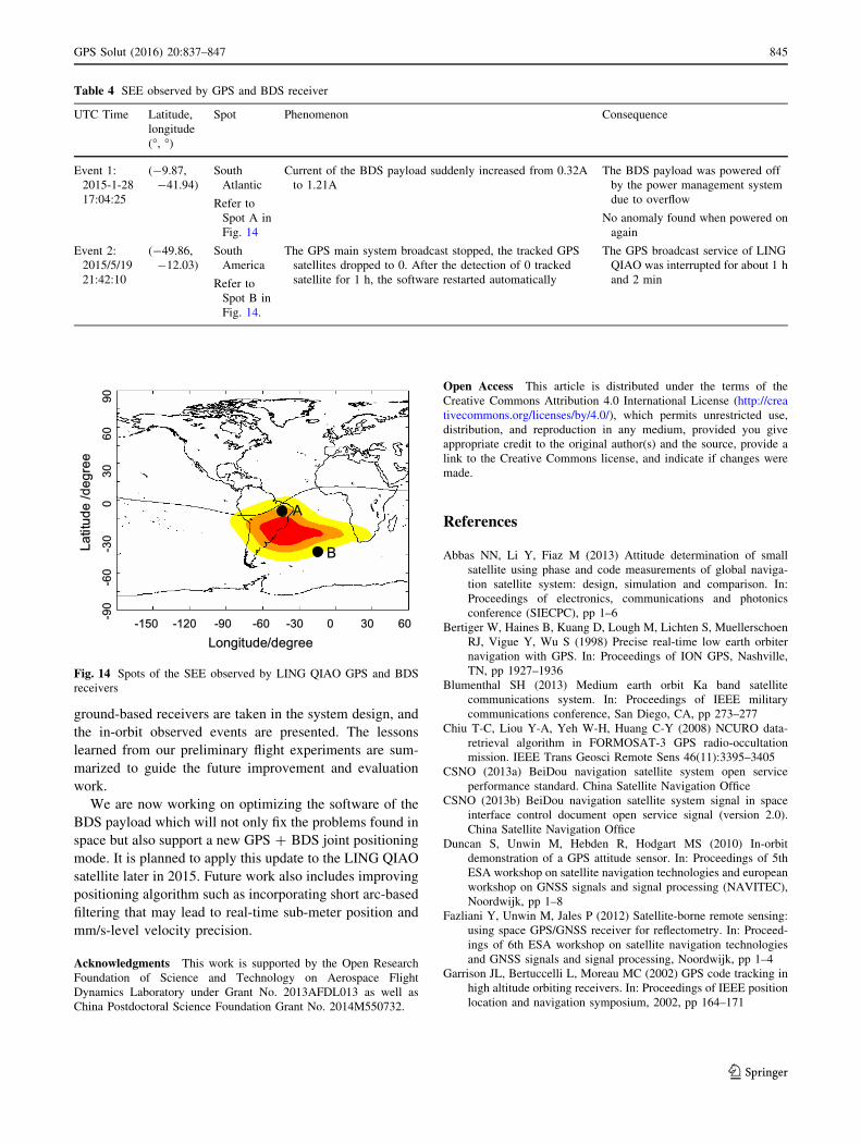
receivers are listed in Table 4. Spots of both the SEE
experienced by LING QIAO GPS and BDS receivers
happened or started in the South Atlantic Anomaly as
shown in Fig. 14.
Lessons learned and possible improvement
From the system design and preliminary in-orbit experi-
ment results, we have learned the following lessons:
1. Due to the limitation of chipsets and reasons of power
saving, the current GPS and BDS receivers of LING
QIAO have a sensitivity of -128 to -130 dBm.
There are still cases where the number of tracked
satellites is lower than the full service capability of
both systems, which are caused by the limited sensi-
tivity. For the BDS receiver, improved baseband
processing capability including Doppler offset predic-
tion is necessary to increase acquisition efficiency.
From analysis and in-orbit results, improved receiver
sensitivity, such as -136 dBm via possible baseband
processing software update, is needed to acquire and
track more navigation satellites, thus making position-
ing results more accurate and robust.
2. As components become increasingly smaller, indus-
trial-level very large-scale integration (VLSI) chips
can tolerate more total ionizing impact than older
generations, but will have become more sensitive to
SEU and SEL. So if allowed, payloads should be
powered off when in South Atlantic Anomaly.
Conclusions and future work
In this research, the system design of the BDS and GPS
receivers of the LING QIAO LEO telecommunication
satellite is presented. The in-orbit performance of this
space-borne BDS receiver experimental payload, including
the number of tracked BDS satellites and the positioning
results, is for the first time reported. The in-orbit traced
service area of the current regional BDS matches the
officially announced service region which is a verification
of the BDS service ability; the position and velocity RMS
errors of the BDS receiver reach about 13 m and 0.2 m/s.
As compared to the GPS receiver on LING QIAO, the
performance of the BDS receiver still has some gaps in
signal tracking ability and positioning accuracy due to the
limitations of the design and mission requirements. Mea-
sures to handle the SEE which are different from those
Fig. 13 Position and velocity
error of the LING QIAO main
GPS receiver and BDS payload
compared with extrapolated
orbit
844 GPS Solut (2016) 20:837–847
123
ground-based receivers are taken in the system design, and
the in-orbit observed events are presented. The lessons
learned from our preliminary flight experiments are sum-
marized to guide the future improvement and evaluation
work.
We are now working on optimizing the software of the
BDS payload which will not only fix the problems found in
space but also support a new GPS ? BDS joint positioning
mode. It is planned to apply this update to the LING QIAO
satellite later in 2015. Future work also includes improving
positioning algorithm such as incorporating short arc-based
filtering that may lead to real-time sub-meter position and
mm/s-level velocity precision.
Acknowledgments This work is supported by the Open Research
Foundation of Science and Technology on Aerospace Flight
Dynamics Laboratory under Grant No. 2013AFDL013 as well as
China Postdoctoral Science Foundation Grant No. 2014M550732.
Open Access This article is distributed under the terms of the
Creative Commons Attribution 4.0 International License (http://crea
tivecommons.org/licenses/by/4.0/), which permits unrestricted use,
distribution, and reproduction in any medium, provided you give
appropriate credit to the original author(s) and the source, provide a
link to the Creative Commons license, and indicate if changes were
made.
References
Abbas NN, Li Y, Fiaz M (2013) Attitude determination of small
satellite using phase and code measurements of global naviga-
tion satellite system: design, simulation and comparison. In:
Proceedings of electronics, communications and photonics
conference (SIECPC), pp 1–6
Bertiger W, Haines B, Kuang D, Lough M, Lichten S, Muellerschoen
RJ, Vigue Y, Wu S (1998) Precise real-time low earth orbiter
navigation with GPS. In: Proceedings of ION GPS, Nashville,
TN, pp 1927–1936
Blumenthal SH (2013) Medium earth orbit Ka band satellite
communications system. In: Proceedings of IEEE military
communications conference, San Diego, CA, pp 273–277
Chiu T-C, Liou Y-A, Yeh W-H, Huang C-Y (2008) NCURO data-
retrieval algorithm in FORMOSAT-3 GPS radio-occultation
mission. IEEE Trans Geosci Remote Sens 46(11):3395–3405
CSNO (2013a) BeiDou navigation satellite system open service
performance standard. China Satellite Navigation Office
CSNO (2013b) BeiDou navigation satellite system signal in space
interface control document open service signal (version 2.0).
China Satellite Navigation Office
Duncan S, Unwin M, Hebden R, Hodgart MS (2010) In-orbit
demonstration of a GPS attitude sensor. In: Proceedings of 5th
ESA workshop on satellite navigation technologies and european
workshop on GNSS signals and signal processing (NAVITEC),
Noordwijk, pp 1–8
Fazliani Y, Unwin M, Jales P (2012) Satellite-borne remote sensing:
using space GPS/GNSS receiver for reflectometry. In: Proceed-
ings of 6th ESA workshop on satellite navigation technologies
and GNSS signals and signal processing, Noordwijk, pp 1–4
Garrison JL, Bertuccelli L, Moreau MC (2002) GPS code tracking in
high altitude orbiting receivers. In: Proceedings of IEEE position
location and navigation symposium, 2002, pp 164–171
Table 4 SEE observed by GPS and BDS receiver
UTC Time Latitude,
longitude
(�, �)
Spot Phenomenon Consequence
Event 1:
2015-1-28
17:04:25
(-9.87,
-41.94)
South
Atlantic
Refer to
Spot A in
Fig. 14
Current of the BDS payload suddenly increased from 0.32A
to 1.21A
The BDS payload was powered off
by the power management system
due to overflow
No anomaly found when powered on
again
Event 2:
2015/5/19
21:42:10
(-49.86,
-12.03)
South
America
Refer to
Spot B in
Fig. 14.
The GPS main system broadcast stopped, the tracked GPS
satellites dropped to 0. After the detection of 0 tracked
satellite for 1 h, the software restarted automatically
The GPS broadcast service of LING
QIAO was interrupted for about 1 h
and 2 min
Fig. 14 Spots of the SEE observed by LING QIAO GPS and BDS
receivers
GPS Solut (2016) 20:837–847 845
123
Girimaji SS (1996) Improved algebraic Reynolds stress model for
engineering flows. In: Rodi W, Bergeles G (eds) Engineering
turbulence modelling and experiments, vol 3. Elsevier, Amster-
dam, pp 121–129
Jin J, Kuang L, Yan J, Chen X, Ni Z, You X, Sun D, Lu J (2015)
Smart communication satellite (SCS)—an application oriented
micro-satellite for communication. In: Proceedings of AIAA
space and astronautics forum and exposition (SPACE), SSC15-
V-12. http://digitalcommons.usu.edu/smallsat/2015/all2015/
2031/
Kang Z, Tapley B, Bettadpur S, Ries J, Nagel P (2006) Precise orbit
determination for GRACE using accelerometer data. Adv Space
Res 38(9):2131–2136
Li Y-S, Hwang C, Tseng T-P, Huang C-Y, Bock H (2014) A near-
real-time automatic orbit determination system for COSMIC and
its follow-on satellite mission: analysis of orbit and clock errors
on radio occultation. IEEE Trans Geosci Remote Sens
52(6):3192–3203
Lowe ST, Meehan T, Young L (2014) Direct signal enhanced
semicodeless processing of GNSS surface-reflected signals.
IEEE J Sel Top Appl Earth Obs Remote Sens 7(5):1469–1472
Montenbruck O, Swatschina P, Markgraf M, Santandrea S, Naudet J,
Tilmans E (2012) Precision spacecraft navigation using a low-
cost GPS receiver. GPS Solut 16(4):519–529
Norman RJ, Dyson PL, Yizengaw E, Marshall JL, Wang C-S, Carter
BA, Wen D, Zhang K (2012) Radio occultation measurements
from the Australian microsatellite FedSat. IEEE Trans Geosci
Remote Sens 50(11):4832–4839
Park H, Camps A, Valencia E, Rodriguez-Alvarez N, Bosch-Lluis X,
Ramos-Perez I, Carreno-Luengo H (2012) Retracking consider-
ations in spaceborne GNSS-R altimetry. GPS Solut
16(4):507–518
Pascual D, Camps A, Martin F, Park H, Arroyo AA, Onrubia R (2014)
Precision bounds in GNSS-R ocean altimetry. IEEE J Sel Top
Appl Earth Obs Remote Sens 7(5):1416–1423
Pendergrass JR, Treder AJ (2000) GPS-updated attitude determina-
tion on ISS despite rich multipath. In: Proceedings of AIAA
guidance, navigation and control conference and exhibit, Den-
ver, CO, AIAA 2000-4469. http://arc.aiaa.org/doi/abs/2010.
2514/2006.2000-4469
Stieglitz JL (1999) Global positioning system receivers in space
applications. In: Proceedings of 18th digital avionics systems
conference, St Louis, MO, pp 7.A.3-1–7.A.3-7
Winternitz LMB, Bamford WA, Heckler GW (2009) A GPS receiver
for high-altitude satellite navigation. IEEE J Sel Top Signal
Process 3(4):541–556
Yoon YT, Eineder M, Montenbruck O (2009) TerraSAR-X precise
trajectory estimation and quality assessment. IEEE Trans Geosci
Remote Sens 47(6):1859–1868
ZarLink (2002) GP4020 GPS baseband processor design manual.
Retrieved 20 June 2015, from http://ulp.zarlink.com/zarlink/hs/
dm5280-design-manual-jan2002.pdf
Xi Chen is currently affiliated
to Space Center, Tsinghua
University, Beijing, China, as an
assistant professor. He received
his B.S. degree in telecommu-
nication engineering from Bei-
jing University of Posts and
Telecommunications, Beijing,
China, in 2001 and his Ph.D.
degree at the Department of
Electronic Engineering, Tsin-
ghua University, Beijing, China,
in 2006. His research interests
include timing and positioning
in space and aero-wireless net-
works, GNSS positioning, passive locating of active radio sources.
Sihao Zhao is an assistant
research fellow at the Depart-
ment of Electronic Engineering,
Tsinghua University, Beijing,
China. His research interests
include GNSS signal processing
algorithms, high-precision posi-
tioning techniques, indoor nav-
igation systems as well as
telecommunication systems
design and verification. He
received his B.S. and Ph.D.
degrees from the Department of
Electronic Engineering, Tsin-
ghua University in 2005 and
2011, respectively.
Menglu Wang graduated from
Beihang University as a Bache-
lor in Electronic Engineering
and is now pursuing her Master
degree in Space Center, Tsin-
ghua University. She is inter-
ested in the research of
navigation and positioning
algorithms, navigation messages
and ephemeris for LEO satel-
lites, positioning using Doppler
shift of LEO satellites and other
GPS/BDS navigation enhance-
ment methods using LEO
satellites.
846 GPS Solut (2016) 20:837–847
123
Mingquan Lu is a professor of
the Department of Electronic
Engineering, Tsinghua Univer-
sity, Beijing, China. He is the
director of Tsinghua GNSS
Research Laboratory and a
member of the Expert Group of
China BeiDou Navigation
Satellite System. His current
research interests include GNSS
signal design and analysis,
GNSS signal processing and
receiver development, GNSS
system modeling and simula-
tion. He received his M.E. and
Ph.D. degrees in Electronic Engineering from University of Elec-
tronic Science and Technology, Chengdu, China.
GPS Solut (2016) 20:837–847 847
123