Embed Size (px)
Citation preview
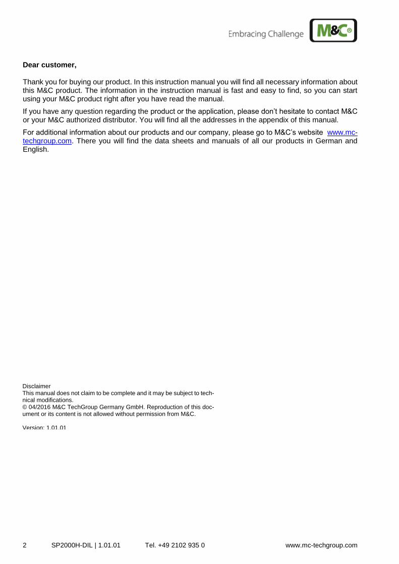
Gas Sample Probes Series SP®
SP2000H/DIL, SP2000H/DIL/B, SP2000H/DIL/BR Instruction Manual Version 1.01.01
2 SP2000H-DIL | 1.01.01 Tel. +49 2102 935 0 www.mc-techgroup.com
Dear customer, Thank you for buying our product. In this instruction manual you will find all necessary information about this M&C product. The information in the instruction manual is fast and easy to find, so you can start using your M&C product right after you have read the manual.
If you have any question regarding the product or the application, please don’t hesitate to contact M&C or your M&C authorized distributor. You will find all the addresses in the appendix of this manual.
For additional information about our products and our company, please go to M&C’s website www.mc-techgroup.com. There you will find the data sheets and manuals of all our products in German and English.
Disclaimer This manual does not claim to be complete and it may be subject to tech-nical modifications. © 04/2016 M&C TechGroup Germany GmbH. Reproduction of this doc-ument or its content is not allowed without permission from M&C. Version: 1.01.01
SP2000H/DIL | 1.01.01 Tel. +49 2102 935 0 www.mc-techgroup.com 3
Table of Content s
1 General information .................................................................................................................... 5 2 Declaration of conformity ........................................................................................................... 5 3 Safety instructions ...................................................................................................................... 6 4 Warranty ...................................................................................................................................... 6 5 Warning signs and definitions ................................................................................................... 7 6 Introduction ................................................................................................................................. 8
6.1 Serial number ........................................................................................................................ 8 7 Description .................................................................................................................................. 8
7.1 Variations ............................................................................................................................. 12 8 Technical Data ........................................................................................................................... 13 9 Dilution principle ....................................................................................................................... 14 10 Dimensions ............................................................................................................................ 15 11 Receiving and storing the sample probe ............................................................................. 15 12 Installation information ......................................................................................................... 15 13 Installation ............................................................................................................................. 16
13.1 Installation of the sample probe ........................................................................................... 16 13.2 Connection of diluted sample outlet tubing ........................................................................... 17 13.3 Connection of supply tubes for dilution bypass gas .............................................................. 18 13.4 Connection of calibrating gas ............................................................................................... 19 13.5 Electrical connection ............................................................................................................ 19
13.5.1 Types with internal capillary tube hermostat .................................................................. 20 13.5.2 Types with external temperature controller.................................................................... 20
14 Commissioning ..................................................................................................................... 20 14.1 Calibration ............................................................................................................................ 23
15 Decommissioning .................................................................................................................. 23 16 Maintenance ........................................................................................................................... 23
16.1 Replacement of filter element and seals .............................................................................. 25 16.2 Dismantling the dilution cross ............................................................................................... 27
16.2.1 Replacing and cleaning the critical orifice (180 °C (356 °F) version) ............................. 28 16.2.2 Changing packing at the critical orifice (320 °C (608 °F) Version) ................................. 29 16.2.3 Changing and cleaning of the injector nozzle ................................................................ 30 16.2.4 Changing o-ring at injector Nozzle (180 °C (356 °F) Version) ....................................... 30 16.2.5 Changing packing at injector nozzle (320 °C (608 °F) Version) ..................................... 31
16.3 Removing Bypass-T for probe option..B/..BR (180 °C (356 °F) version) ............................... 32 16.3.1 Changing and cleaning of the bypass-T (180 °C (356 °F) version) ................................ 32 16.3.2 Changing O-ring at bypass injector nozzle (180 °C (356 °F) Version) ........................... 33 16.3.3 Changing graphite packing at bypass injector nozzle (320 °C (608 °F) version) ............ 34
17 Spare parts ............................................................................................................................. 35 18 Appendix ................................................................................................................................ 36
4 SP2000H-DIL | 1.01.01 Tel. +49 2102 935 0 www.mc-techgroup.com
Table of Figures
Figure 1 Probe type SP2000H/DIL/2x wit second sample outlet (undiluted)................................... 8
Figure 2 Probe type SP2000H/DIL/VA/B ....................................................................................... 9
Figure 3 Probe type SP2000H/DIL/BR ......................................................................................... 10
Figure 4 Installation set and control panel ................................................................................... 11
Figure 5 Gas flow pattern of available probe variants .................................................................. 12
Figure 6 Dilution principle ............................................................................................................ 14
Figure 7 Dimensions (mm) of SP2000H/DIL probe ...................................................................... 15
Figure 8 SP2000H/DIL/B with control panel DIL/S1 ..................................................................... 18
Figure 9 Extract from an injector data sheet ................................................................................ 22
Figure 10 Bypass injector data sheet ......................................................................................... 22
Figure 11 Cross-sectional drawing SP2000-H ............................................................................ 25
Figure 12 Removing the new filter housing lid ............................................................................ 26
Figure 13 Exploded drawing of dilution unit ................................................................................ 27
Figure 14 Crosspiece with critical orifice and o-ring seals (180°C (356 °F) version) ................... 28
Figure 15 Dilution cross with graphite packing (320 °C (608 °F) Version) .................................. 29
Figure 16 Injector 320°C (608 °F) version with graphite packing ................................................ 31
Figure 17 Bypass-T with Injector and o-ring (180°C (356 °F) version) ........................................ 32
Figure 18 Bypass Injector unit with o-ring (180 °C (356 °F) version) .......................................... 33
Figure 19 Bypass Injector unit with graphite packing (320°C (608 °F) version) .......................... 34
SP2000H/DIL | 1.01.01 Tel. +49 2102 935 0 www.mc-techgroup.com 5
Head quarters M&C TechGroup Germany GmbH Rehhecke 79 40885 Ratingen Germany Telephone: 02102 / 935 - 0 Fax: 02102 / 935 - 111 E - mail: [email protected] www.mc-techgroup.com
1 GENERAL INFORMATION
The product described in this manual has been built and tested in our production facility.
All M&C products are packed to be shipped safely. To ensure the safe operation and to maintain the safe condition, all instructions and regulations stated in this manual need to be followed. This manual includes all information regarding proper transportation, storage, installation, operation and mainte-nance of this product by qualified personnel.
Please follow all instructions and warnings closely.
Please read this manual carefully before commissioning and operating the device. If you have any ques-tions regarding the product or the application, please don’t hesitate to contact M&C or your M&C au-thorized distributor.
2 DECLARATION OF CONFORMITY
CE - Certification The product described in this operating manual complies with the following EU directives: EMV-Instruction The requirements of the EU directive 2014/30/EU “Electromagnetic compatibility“ are met. Low Voltage Directive The requirement of the EU directive 2014/35/EU “Low Voltage Directive“ are met. The compliance with this EU directive has been examined according to DIN EN 61010. Declaration of conformity The EU Declaration of conformity can be downloaded from the M&C homepage or directly requested from M&C.
6 SP2000H-DIL | 1.01.01 Tel. +49 2102 935 0 www.mc-techgroup.com
3 SAFETY INSTRUCTIONS
Follow these safety directions and instructions regarding installation, commissioning and op-eration of the SP2000H/DIL:
Read this manual before commissioning and operating the product. Make sure to follow all safety in-structions.
Installation and commissioning of electrical devices must be carried out only by qualified skilled person-nel in compliance with the current regulations.
The installation and commissioning of the device must conform to the requirements of VDE 0100 (IEC 364) ‘Regulations on the Installation of Power Circuits with Nominal Voltages below 1000 V’ and must be in compliance with all relevant regulations and standards.
Before connecting the device, please make sure to compare the supply voltage with the specified volt-age on the product label.
Protection against damages caused by high voltages:
Disconnect the power supply before opening the device for access. Make sure that all extern power supplies are disconnected.
Operate the device only in the permitted temperature and pressure ranges. For details please refer to the technical data sheet or manual.
Install the device only in protected areas, sheltered from rain and moisture. The product should not be exposure to the elements.
This device is NOT certified to be installed or operated in explosive hazardous areas.
Installation, maintenance, inspections and any repairs of the devices must be carried out only by quali-fied skilled personnel in compliance with the current regulations.
4 WARRANTY
In case of a device failure, please contact immediately M&C or your M&C authorized distributor.
We have a warranty period of 12 months from the delivery date. The warranty covers only appropriately used products and does not cover the consumable parts. Please find the complete warranty conditions in our terms and conditions.
The warranty includes a free-of-charge repair in our production facility or the free replacement of the device. If you return a device to M&C, please be sure that it is properly packaged and shipped with protective packaging. The repaired or replaced device will be shipped free of delivery charges to the point of use.
SP2000H/DIL | 1.01.01 Tel. +49 2102 935 0 www.mc-techgroup.com 7
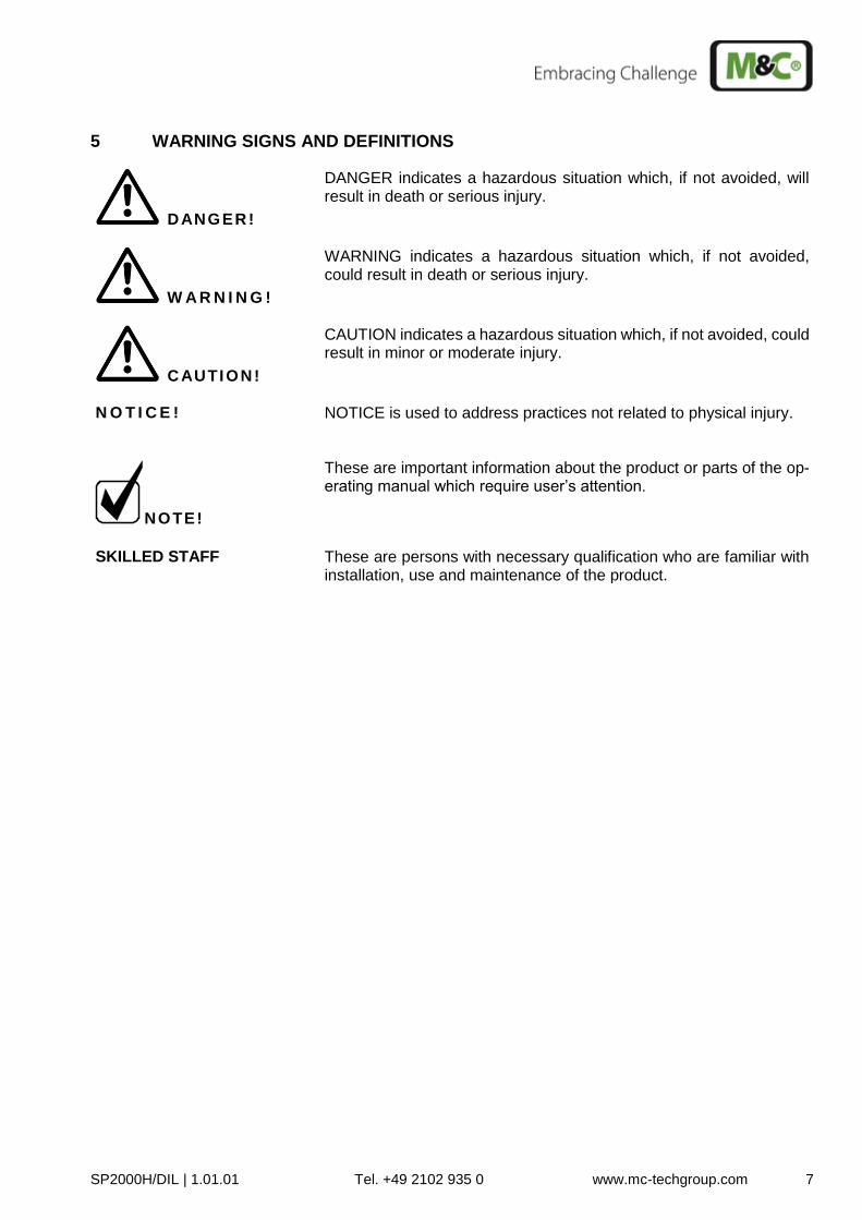
5 WARNING SIGNS AND DEFINITIONS
DANGER!
DANGER indicates a hazardous situation which, if not avoided, will result in death or serious injury.
W A R N I N G !
WARNING indicates a hazardous situation which, if not avoided, could result in death or serious injury.
CAUTION!
CAUTION indicates a hazardous situation which, if not avoided, could result in minor or moderate injury.
N O T I C E ! NOTICE is used to address practices not related to physical injury.
NOTE!
These are important information about the product or parts of the op-erating manual which require user’s attention.
SKILLED STAFF These are persons with necessary qualification who are familiar with
installation, use and maintenance of the product.
8 SP2000H-DIL | 1.01.01 Tel. +49 2102 935 0 www.mc-techgroup.com
6 INTRODUCTION
Dilution probes are used wherever dilution of the sample gas is necessary for the measurement of one or several sample gas components. Examples are the measurement of toxic gas components, moisture measurements or adjustment of the sample gas concentration to the analyser measuring range. M&C dilution probes type SP2000H/DIL... are based on the modular probe type SP2000-H. The diverse variants, filter techniques and materials available ensure optimal adjustment to the particular process conditions.
6.1 SERIAL NUMBER
The product label with the serial number is located inside the terminal box of the sample probe. Please refer to this serial number if you have any questions about your sample probe or if you need to order spare parts or consumables.
7 DESCRIPTION
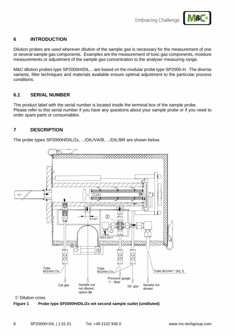
The probe types SP2000H/DIL/2x, .../DIL/VA/B, .../DIL/BR are shown below.
Sample out diluted
Pressure gauge -1…0bar
Cal gas Dil. gas
6x1mm o. Tube 8x1mm * (Inj. I) Sample out not diluted
option 2x
1/4"NPT
Dilution gas in
Tube 6x1mm o. Tube
Dilution cross
Figure 1 Probe type SP2000H/DIL/2x wit second sample outlet (undiluted)
SP2000H/DIL | 1.01.01 Tel. +49 2102 935 0 www.mc-techgroup.com 9
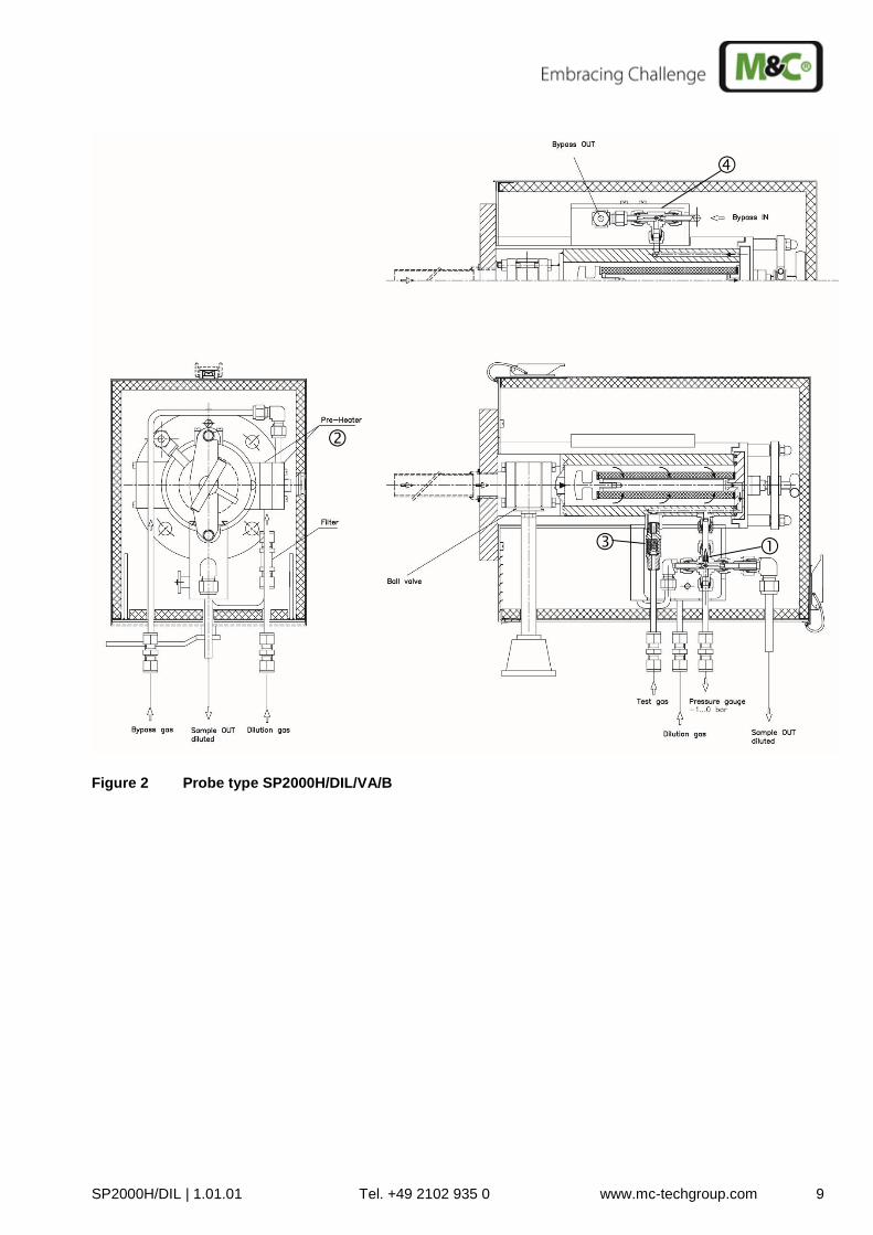
Figure 2 Probe type SP2000H/DIL/VA/B
10 SP2000H-DIL | 1.01.01 Tel. +49 2102 935 0 www.mc-techgroup.com
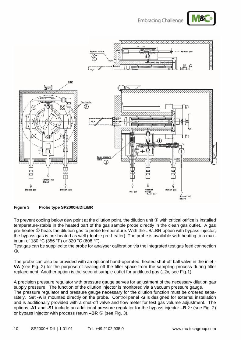
Figure 3 Probe type SP2000H/DIL/BR
To prevent cooling below dew point at the dilution point, the dilution unit with critical orifice is installed temperature-stable in the heated part of the gas sample probe directly in the clean gas outlet. A gas
pre-heater heats the dilution gas to probe temperature. With the ..B/..BR option with bypass injector, the bypass gas is pre-heated as well (double pre-heater). The probe is available with heating to a max-imum of 180 °C (356 °F) or 320 °C (608 °F). Test gas can be supplied to the probe for analyser calibration via the integrated test gas feed connection
. The probe can also be provided with an optional hand-operated, heated shut-off ball valve in the inlet -VA (see Fig. 2) for the purpose of sealing off the filter space from the sampling process during filter replacement. Another option is the second sample outlet for undiluted gas (..2x, see Fig.1) A precision pressure regulator with pressure gauge serves for adjustment of the necessary dilution gas supply pressure. The function of the dilution injector is monitored via a vacuum pressure gauge. The pressure regulator and pressure gauge necessary for the dilution function must be ordered sepa-rately. Set -A is mounted directly on the probe. Control panel -S is designed for external installation and is additionally provided with a shut-off valve and flow meter for test gas volume adjustment. The
options -A1 and -S1 include an additional pressure regulator for the bypass injector –B (see Fig. 2)
or bypass injector with process return –BR (see Fig. 3).
SP2000H/DIL | 1.01.01 Tel. +49 2102 935 0 www.mc-techgroup.com 11
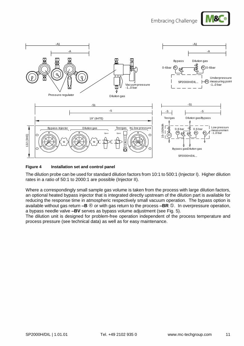
Figure 4 Installation set and control panel
The dilution probe can be used for standard dilution factors from 10:1 to 500:1 (Injector I). Higher dilution rates in a ratio of 50:1 to 2000:1 are possible (Injector II). Where a correspondingly small sample gas volume is taken from the process with large dilution factors, an optional heated bypass injector that is integrated directly upstream of the dilution part is available for reducing the response time in atmospheric respectively small vacuum operation. The bypass option is
available without gas return –B or with gas return to the process –BR . In overpressure operation, a bypass needle valve –BV serves as bypass volume adjustment (see Fig. 5). The dilution unit is designed for problem-free operation independent of the process temperature and process pressure (see technical data) as well as for easy maintenance.
Pressure regulator
-A
-A1-A1
-A
-1...0 barmeasuring pointSP2000H/DIL...
0-6bar PI
Dilution gas
0-6barPI
PI
Underpressure
Bypass Dilution gas
Vacuum pressure-1...0 bar
13
2 (
3H
E)
19" (84TE)
SP2000H/DIL...
-S1
-S -S
Open
Test gas Inj.-low pressure
Open
Dilution gasBypass-Injector
-S
-S1
Bypass gas
measurementPI
0-6 bar
15
-15
0N
l/h
-1..0 bar
0-6 bar
FIPI PI
Low pressure
Test gas Dilution gas/Bypass
Dilution gas
12 SP2000H-DIL | 1.01.01 Tel. +49 2102 935 0 www.mc-techgroup.com
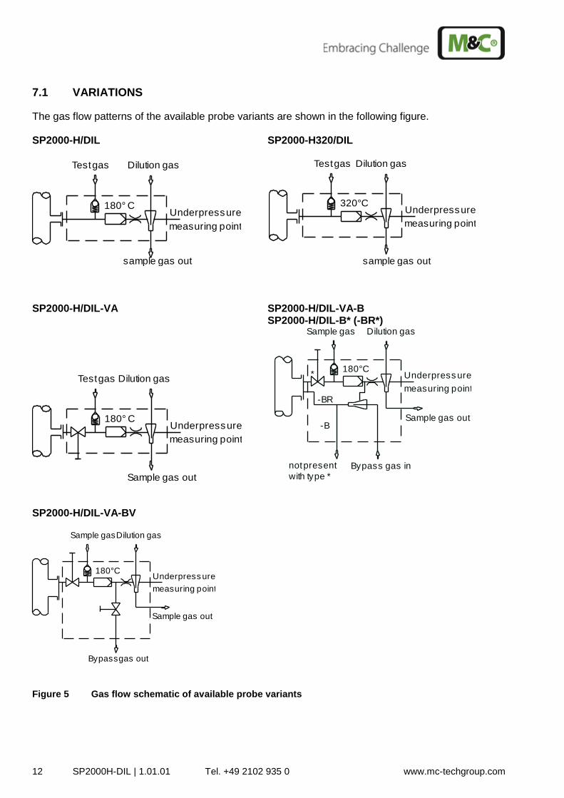
7.1 VARIATIONS
The gas flow patterns of the available probe variants are shown in the following figure. SP2000-H/DIL SP2000-H320/DIL
SP2000-H/DIL-VA SP2000-H/DIL-VA-B SP2000-H/DIL-B* (-BR*)
SP2000-H/DIL-VA-BV
Figure 5 Gas flow schematic of available probe variants
Dilution gas
measuring point
sample gas out
Underpressure180° C
Test gas
Underpressure
measuring point
Test gas
320°C
Dilution gas
sample gas out
180° C
Test gas Dilution gas
measuring point
Sample gas out
Underpressure
not present
with type *
-B
-BR
Bypass gas in
*
Sample gas Dilution gas
Underpress ure
measuring point
180°C
Sample gas out
Underpress ure
measuring point
Sample gas
180°C
Dilution gas
Sample gas out
Bypassgas out
SP2000H/DIL | 1.01.01 Tel. +49 2102 935 0 www.mc-techgroup.com 13
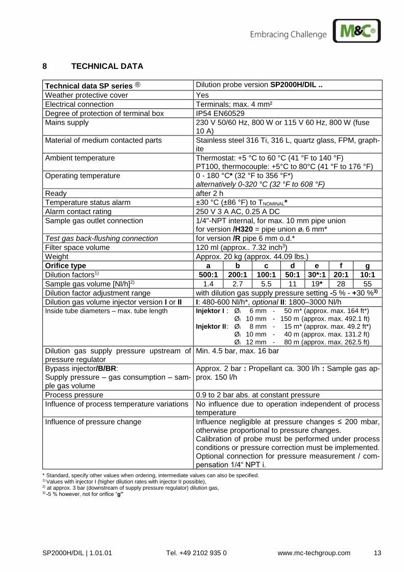
8 TECHNICAL DATA
Technical data SP series ® Dilution probe version SP2000H/DIL ..
Weather protective cover Yes
Electrical connection Terminals; max. 4 mm²
Degree of protection of terminal box IP54 EN60529
Mains supply 230 V 50/60 Hz, 800 W or 115 V 60 Hz, 800 W (fuse 10 A)
Material of medium contacted parts Stainless steel 316 Ti, 316 L, quartz glass, FPM, graph-ite
Ambient temperature
Thermostat: +5 °C to 60 °C (41 °F to 140 °F) PT100, thermocouple: +5°C to 80°C (41 °F to 176 °F)
Operating temperature 0 - 180 °C* (32 °F to 356 °F*) alternatively 0-320 °C (32 °F to 608 °F)
Ready after 2 h
Temperature status alarm ±30 °C (±86 °F) to TNOMINAL*
Alarm contact rating 250 V 3 A AC, 0.25 A DC
Sample gas outlet connection 1/4"-NPT internal, for max. 10 mm pipe union for version /H320 = pipe union øi 6 mm*
Test gas back-flushing connection for version /R pipe 6 mm o.d.*
Filter space volume 120 ml (approx.. 7.32 inch3)
Weight Approx. 20 kg (approx. 44.09 lbs.)
Orifice type a b c d e f g
Dilution factors1) 500:1 200:1 100:1 50:1 30*:1 20:1 10:1
Sample gas volume [Nl/h]2) 1.4 2.7 5.5 11 19* 28 55
Dilution factor adjustment range with dilution gas supply pressure setting -5 % - +30 %3)
Dilution gas volume injector version I or II I: 480-600 Nl/h*, optional II: 1800–3000 Nl/h Inside tube diameters – max. tube length Injektor I : Øi 6 mm - 50 m* (approx. max. 164 ft*)
Øi 10 mm - 150 m (approx. max. 492.1 ft) Injektor II : Øi 8 mm - 15 m* (approx. max. 49.2 ft*) Øi 10 mm - 40 m (approx. max. 131.2 ft) Øi 12 mm - 80 m (approx. max. 262.5 ft)
Dilution gas supply pressure upstream of pressure regulator
Min. 4.5 bar, max. 16 bar
Bypass injector/B/BR: Supply pressure – gas consumption – sam-ple gas volume
Approx. 2 bar : Propellant ca. 300 l/h : Sample gas ap-prox. 150 l/h
Process pressure 0.9 to 2 bar abs. at constant pressure
Influence of process temperature variations No influence due to operation independent of process temperature
Influence of pressure change Influence negligible at pressure changes ≤ 200 mbar, otherwise proportional to pressure changes. Calibration of probe must be performed under process conditions or pressure correction must be implemented. Optional connection for pressure measurement / com-pensation 1/4“ NPT i.
* Standard, specify other values when ordering, intermediate values can also be specified. 1) Values with injector I (higher dilution rates with injector II possible), 2) at approx. 3 bar (downstream of supply pressure regulator) dilution gas, 3) -5 % however, not for orifice “g”
14 SP2000H-DIL | 1.01.01 Tel. +49 2102 935 0 www.mc-techgroup.com
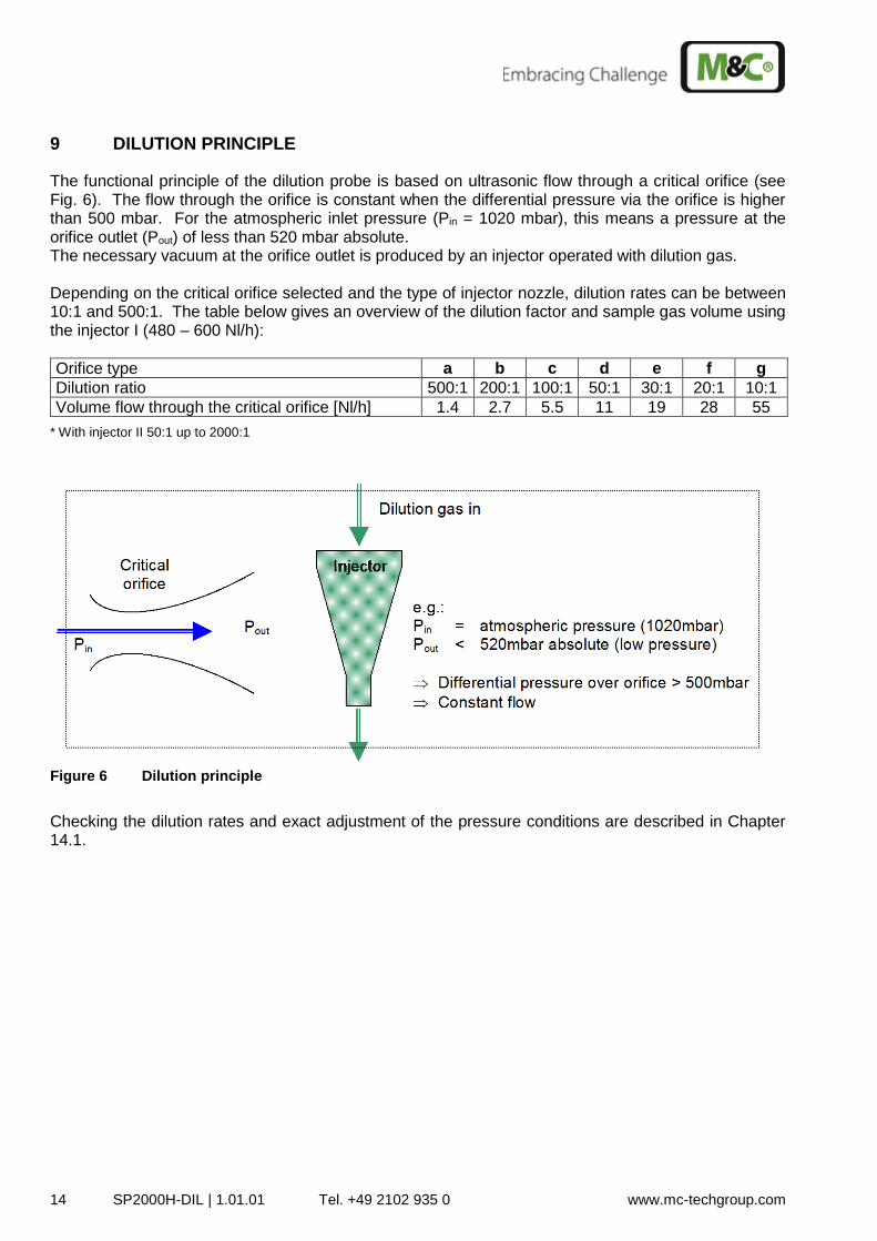
9 DILUTION PRINCIPLE
The functional principle of the dilution probe is based on ultrasonic flow through a critical orifice (see Fig. 6). The flow through the orifice is constant when the differential pressure via the orifice is higher than 500 mbar. For the atmospheric inlet pressure (Pin = 1020 mbar), this means a pressure at the orifice outlet (Pout) of less than 520 mbar absolute. The necessary vacuum at the orifice outlet is produced by an injector operated with dilution gas. Depending on the critical orifice selected and the type of injector nozzle, dilution rates can be between 10:1 and 500:1. The table below gives an overview of the dilution factor and sample gas volume using the injector I (480 – 600 Nl/h):
Orifice type a b c d e f g
Dilution ratio 500:1 200:1 100:1 50:1 30:1 20:1 10:1
Volume flow through the critical orifice [Nl/h] 1.4 2.7 5.5 11 19 28 55 * With injector II 50:1 up to 2000:1
Figure 6 Dilution principle
Checking the dilution rates and exact adjustment of the pressure conditions are described in Chapter 14.1.
SP2000H/DIL | 1.01.01 Tel. +49 2102 935 0 www.mc-techgroup.com 15
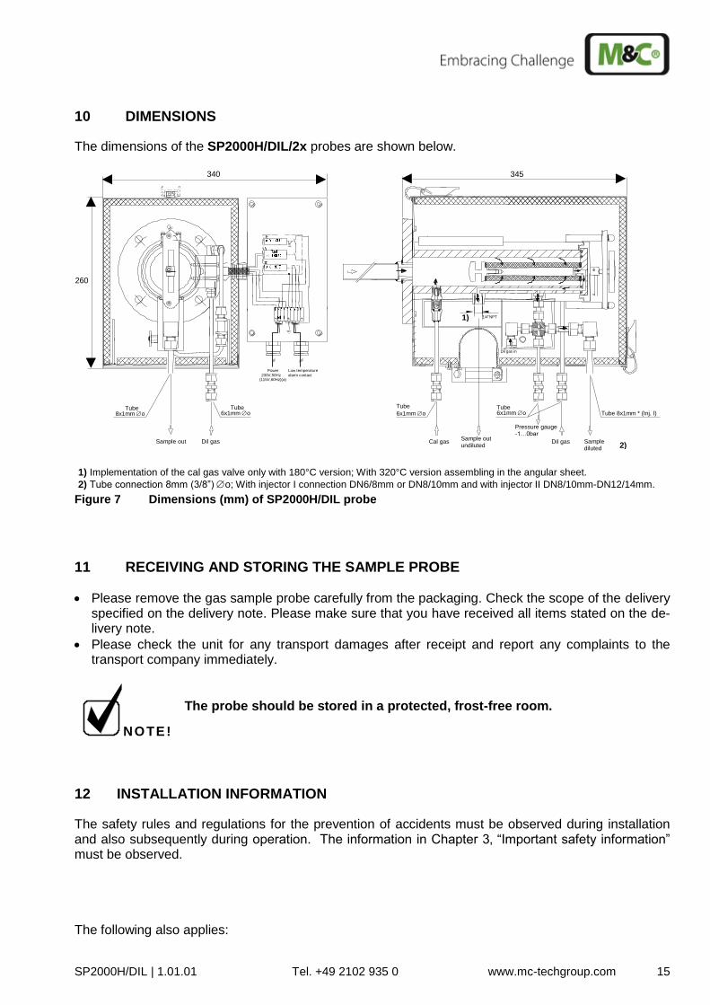
10 DIMENSIONS
The dimensions of the SP2000H/DIL/2x probes are shown below.
Power 230V,50Hz
(115V,60Hz)(a) Low temperature alarm contact
Sample out Dil gas
8x1mm o Tube Tube 6x1mm o Tube
Sample diluted
Pressure gauge -1…0bar
Cal gas Dil gas
Tube 8x1mm * (Inj. I) Sample out undiluted
1/4"NPT
Dil gas in
6x1mm o Tube 6x1mm o
260
345 340
1) Implementation of the cal gas valve only with 180°C version; With 320°C version assembling in the angular sheet.
2) Tube connection 8mm (3/8”) o; With injector I connection DN6/8mm or DN8/10mm and with injector II DN8/10mm-DN12/14mm.
1)
2)
Figure 7 Dimensions (mm) of SP2000H/DIL probe
11 RECEIVING AND STORING THE SAMPLE PROBE
Please remove the gas sample probe carefully from the packaging. Check the scope of the delivery specified on the delivery note. Please make sure that you have received all items stated on the de-livery note.
Please check the unit for any transport damages after receipt and report any complaints to the transport company immediately.
NOTE!
The probe should be stored in a protected, frost-free room.
12 INSTALLATION INFORMATION
The safety rules and regulations for the prevention of accidents must be observed during installation and also subsequently during operation. The information in Chapter 3‚ “Important safety information” must be observed. The following also applies:
16 SP2000H-DIL | 1.01.01 Tel. +49 2102 935 0 www.mc-techgroup.com
Select the optimal sampling point according to the generally applicable directives or co-ordinate with the responsible departments.
Place the sampling point so, that sufficient space is available for installation and removal of the probe, taking into account the insertion length of the sample pipe.
Ensure good access to the probe for ease of maintenance.
Dimension the local sample connection so, that the temperature of the connection is always above the acid dew point to prevent corrosion and blockage problems. If this is not possible, a heated sample pipe type SP35/SP30 is recommended for a cold orifice.
If the ambient temperature in the connection area is >60 °C (> 140 °F) due to radiated heat, a radiant heat reflection plate must be provided locally for protection of the probe.
The mounting flange connection of the orifice should be DN65 PN6 or 3“ANSI (115 V version). For other required connection dimensions, an optional adapter intermediate flange is available. Instead of fitting a flanged orifice, the probe can also be fitted with an available R2" connection adapter to an appropriate pipe coupling connection. The necessary, minimum flange size or minimum con-nection diameter depends on the sample pipe or pre-filter diameter used.
It is recommended to fit the probe horizontally with an angle of inclination of 10° towards the process.
NOTE!
The probe must be checked for its suitability for use with the available oper-ating parameters prior to installation (see type plate).
13 INSTALLATION
M&C SP2000H/DIL... probes are designed for stationary use. With correct selection of the sample point and proper installation, they will give many years of service with a minimum of required maintenance.
13.1 INSTALLATION OF THE SAMPLE PROBE
Open two toggle-type fasteners and remove probe cover.
Turn stirrup bolt at the top end of the filter holder several times anti-clockwise until the retaining bracket can be turned laterally to the left.
Remove filter holder from the probe and check if the filter element is screwed in tightly. Then refit filter holder.
Bring retaining bracket into previous position and tighten stirrup bolt hand-tight.
Remove heat conducting plates at sample gas outlets after loosening knurled screw. For connecting the sample pipe, screw in an appropriately dimensioned pipe union with 1/4"-NPT threaded con-nection using PTFE sealing tape.
NOTE!
Check pipe unions for tightness.
Screw supplied sample pipe or pre-filter directly, or using an extension pipe, into the 3/4" internal thread of the probe flange with 3/4" flat gasket and tighten it. If the heated sample pipe type SP30/35 or the ceramic pre-filter type V12 is used, the probe must be bolted to its flange (with welded threaded studs). The flange seal must previously be placed between both flanges.
SP2000H/DIL | 1.01.01 Tel. +49 2102 935 0 www.mc-techgroup.com 17
NOTE!
When using the heated sample pipe or pre-filter V12 in conjunction with probes with the bypass return option ..BR, a short-circuit between the bypass gas and sample inlet in the centre of the probe flange (filter) must be prevented or low sample gas readings will be obtained. Make sure that the gasket for the mounting flange does not block the bypass return connection or the probe will not function properly. Special flange seals are available at M&C.
If the sample connection does not correspond with the flange connection DN65 PN6, the supplied optional adapter flange must be fitted to the probe in the same way.
Position flange seal on sample connection.
Insert process-internal sample part of complete probe unit into sample connection.
Bolt mating and probe flange with supplied nuts and bolts.
NOTE!
For the preferred probe mounting position, the sample gas outlet points down-ward (unnecessary for perfect functioning).
It is recommended to install the probe with a slight downward inclination to-wards the process. This is essential for sampling, e.g. downstream of wet scrubber (sample pipe type SP32), so that produced drops flow back into the process.
13.2 CONNECTION OF DILUTED SAMPLE OUTLET TUBING
Provided on the probe side for connection of the sample outlet tubing is an elbow union with the dimen-
sion DN6/8mm (3/8“ o for 115 V version; optional also DN 8/10 mm) in the space below the insulating cover.
NOTE!
Excess backpressure on the sample outlet of the probe can result in poor per-formance. The maximum recommended tube length for common inside tube diameters are as follows: Injector type I:
i 6 mm max. 50 m (approx. max. 164 ft)
i 8 mm max. 150 m (approx. max. 492.1 ft)
Injector type II:
i 8 mm max. 15 m (approx. max. 49.2 ft)
i 10 mm max. 40 m (approx. max. 131.2 ft)
i 12 mm max. 80 m (approx. max. 262.5 ft) Install the sample tube as following:
Loosen toggle-type fasteners of insulating cover and remove the cover.
Insert tube through corresponding opening in base plate of the probe.
Connect tube to union.
NOTE!
When connecting hose pipes to stainless steel fittings, a supporting sleeve must always be used. The connection must be checked for tightness.
Refit probe cover and lock with toggle-type fasteners.
18 SP2000H-DIL | 1.01.01 Tel. +49 2102 935 0 www.mc-techgroup.com
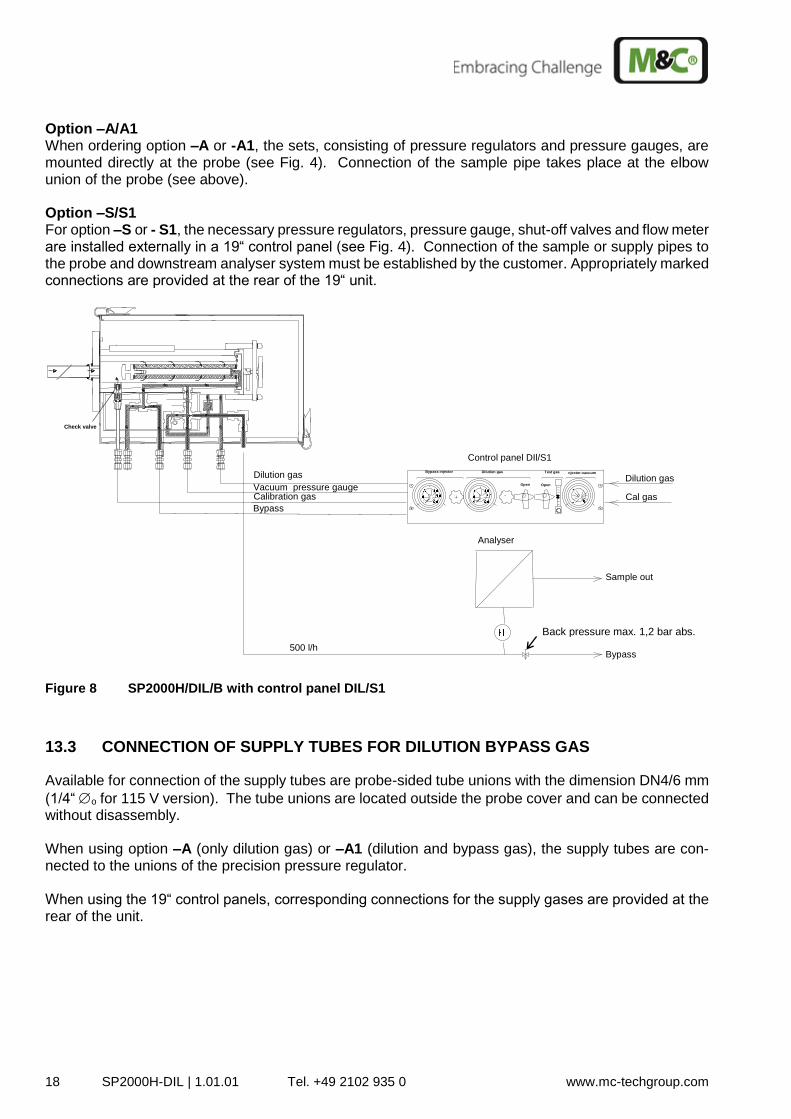
Option –A/A1 When ordering option –A or -A1, the sets, consisting of pressure regulators and pressure gauges, are mounted directly at the probe (see Fig. 4). Connection of the sample pipe takes place at the elbow union of the probe (see above). Option –S/S1 For option –S or - S1, the necessary pressure regulators, pressure gauge, shut-off valves and flow meter are installed externally in a 19“ control panel (see Fig. 4). Connection of the sample or supply pipes to the probe and downstream analyser system must be established by the customer. Appropriately marked connections are provided at the rear of the 19“ unit.
Test gas njector-vacuum Dilution gas Bypass injector
Open Open
500 l/h
Check valve
Calibration gas Dilution gas Vacuum pressure gauge Bypass
Control panel DIl/S1 Dilution gas Cal gas
Sample out
Bypass
Analyser
Figure 8 SP2000H/DIL/B with control panel DIL/S1
13.3 CONNECTION OF SUPPLY TUBES FOR DILUTION BYPASS GAS
Available for connection of the supply tubes are probe-sided tube unions with the dimension DN4/6 mm
(1/4“ o for 115 V version). The tube unions are located outside the probe cover and can be connected without disassembly. When using option –A (only dilution gas) or –A1 (dilution and bypass gas), the supply tubes are con-nected to the unions of the precision pressure regulator. When using the 19“ control panels, corresponding connections for the supply gases are provided at the rear of the unit.
Back pressure max. 1,2 bar abs.
SP2000H/DIL | 1.01.01 Tel. +49 2102 935 0 www.mc-techgroup.com 19
13.4 CONNECTION OF CALIBRATION GAS
The heated dilution probe is provided with a check valve as standard, opening at pressures above 0.7 bar.
In both versions, a pipe union DN4/6 mm (1/4“ o for 115 V version) is available for connecting the calibration gas.
13.5 ELECTRICAL CONNECTION
Temperature setting of the SP2000H/DIL... probes takes place with a capillary regulator as standard. The probe can also be provided with an optional PT100 or thermocouple. This requires the connection of an external temperature controller.
W A R N I N G !
An incorrect mains voltage can damage the unit. Check the type plate for the correct voltage prior to connection!
The probe must be installed so that contact with live parts is ex-cluded!
In any case we recommend the use of temperature resistant cable !
The alarm contact for under-temperature must be monitored!
In case of an under-temperature alarm (failure of probe heating or sensor), the dilution gas and bypass gas supply (if equipped) must be interrupted or the probe will be seriously damaged. We recom-mend external solenoid valves wired into the probe’s under-temper-ature alarm circuitry to automatically perform this function.
NOTE!
Setting up of electrical power installations must be conform to the requirements of IEC 364 (DIN VDE 0100) ‘Regulations on the Installation of Power Circuits with Nominal Voltages below 1000V’, and must be in compliance with all relevant regulations and standards. A main switch must be provided externally.
The supply circuit of the unit must be protected by a fuse with the correct rating (over-current protection); the electrical values are shown in the technical data.
When installing the capillary regulator or PID controller at the sam-ple point, the maximum permissible ambient temperature must be observed (see chapter 8). If this limit is exceeded, a PID controller must be installed externally and outside the temperature critical zone.
20 SP2000H-DIL | 1.01.01 Tel. +49 2102 935 0 www.mc-techgroup.com
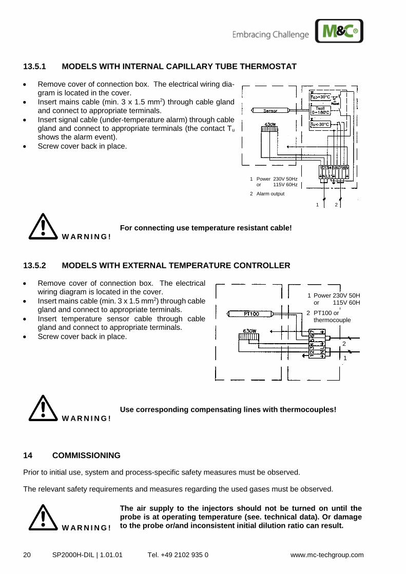
13.5.1 MODELS WITH INTERNAL CAPILLARY TUBE THERMOSTAT
Remove cover of connection box. The electrical wiring dia-gram is located in the cover.
Insert mains cable (min. 3 x 1.5 mm2) through cable gland and connect to appropriate terminals.
Insert signal cable (under-temperature alarm) through cable gland and connect to appropriate terminals (the contact Tu shows the alarm event).
Screw cover back in place.
W A R N I N G !
For connecting use temperature resistant cable!
13.5.2 MODELS WITH EXTERNAL TEMPERATURE CONTROLLER
Remove cover of connection box. The electrical wiring diagram is located in the cover.
Insert mains cable (min. 3 x 1.5 mm2) through cable gland and connect to appropriate terminals.
Insert temperature sensor cable through cable gland and connect to appropriate terminals.
Screw cover back in place.
W A R N I N G !
Use corresponding compensating lines with thermocouples!
14 COMMISSIONING
Prior to initial use, system and process-specific safety measures must be observed. The relevant safety requirements and measures regarding the used gases must be observed.
W A R N I N G !
The air supply to the injectors should not be turned on until the probe is at operating temperature (see. technical data). Or damage to the probe or/and inconsistent initial dilution ratio can result.
Power 230V 50Hz or 115V 60Hz
Alarm output
1
2
1 2
+30°C
-30°C
Power 230V 50Hz or 115V 60Hz
PT100 or thermocouple
1
2
1
2
SP2000H/DIL | 1.01.01 Tel. +49 2102 935 0 www.mc-techgroup.com 21
Prior to initial use, it must be ensured that the mains voltage corre-sponds with the voltage on the type plate!
Caution: Do not touch the probe surface during use. Touching the hot surface can cause burns due to the high surface temperatures. Protective gloves must be worn and the probe protected against un-authorised access!
The following step-by-step procedure is recommended:
If available, close ball valve via pneumatic actuator or manually (turn twist handle fully to the right)
Check set temperature on installed thermostat or external controller.
NOTE!
If the set temperature on the capillary controller should be reduced by more than 30°C (86 °F) in one step during operation, the thermo-stat over-temperature cut-out will operate (for re-starting press the reset button).
Switch on the mains voltage.
NOTE!
The total heating time is about two hours. After about one hour, the lower alarm limit value (30 °C (86 °F) below set value) is exceeded.
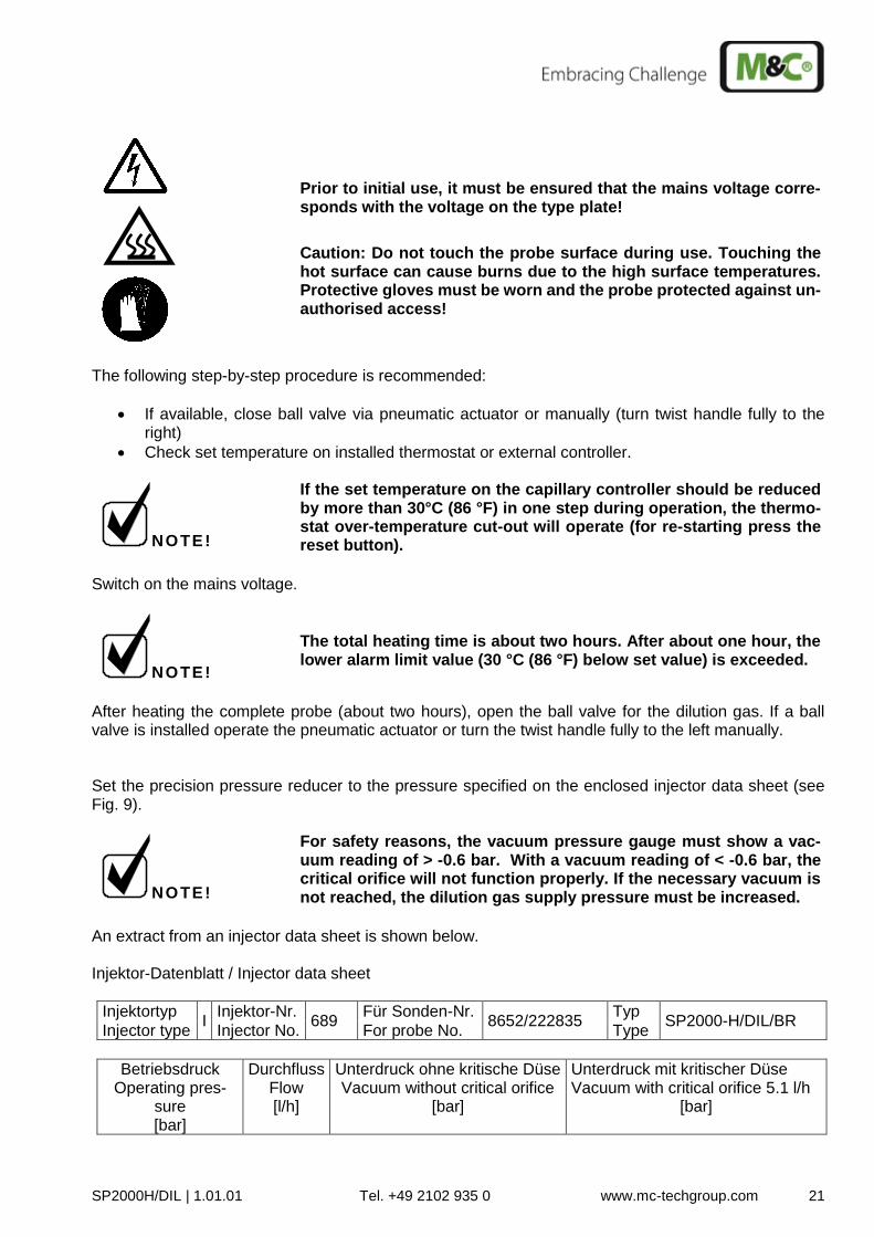
After heating the complete probe (about two hours), open the ball valve for the dilution gas. If a ball valve is installed operate the pneumatic actuator or turn the twist handle fully to the left manually. Set the precision pressure reducer to the pressure specified on the enclosed injector data sheet (see Fig. 9).
NOTE!
For safety reasons, the vacuum pressure gauge must show a vac-uum reading of > -0.6 bar. With a vacuum reading of < -0.6 bar, the critical orifice will not function properly. If the necessary vacuum is not reached, the dilution gas supply pressure must be increased.
An extract from an injector data sheet is shown below. Injektor-Datenblatt / Injector data sheet
Injektortyp I
Injektor-Nr. 689
Für Sonden-Nr. 8652/222835
Typ SP2000-H/DIL/BR
Injector type Injector No. For probe No. Type
Betriebsdruck Operating pres-
sure [bar]
Durchfluss Flow [l/h]
Unterdruck ohne kritische Düse Vacuum without critical orifice
[bar]
Unterdruck mit kritischer Düse Vacuum with critical orifice 5.1 l/h
[bar]
22 SP2000H-DIL | 1.01.01 Tel. +49 2102 935 0 www.mc-techgroup.com
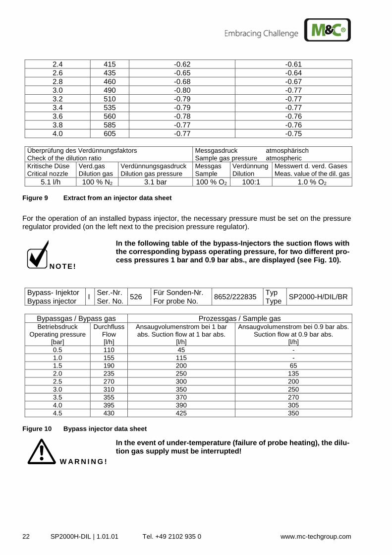
2.4 415 -0.62 -0.61
2.6 435 -0.65 -0.64
2.8 460 -0.68 -0.67
3.0 490 -0.80 -0.77
3.2 510 -0.79 -0.77
3.4 535 -0.79 -0.77
3.6 560 -0.78 -0.76
3.8 585 -0.77 -0.76
4.0 605 -0.77 -0.75
Überprüfung des Verdünnungsfaktors Check of the dilution ratio
Messgasdruck atmosphärisch Sample gas pressure atmospheric
Kritische Düse Critical nozzle
Verd.gas Dilution gas
Verdünnungsgasdruck Dilution gas pressure
Messgas Sample
Verdünnung Dilution
Messwert d. verd. Gases Meas. value of the dil. gas
5.1 l/h 100 % N2 3.1 bar 100 % O2 100:1 1.0 % O2
Figure 9 Extract from an injector data sheet
For the operation of an installed bypass injector, the necessary pressure must be set on the pressure regulator provided (on the left next to the precision pressure regulator).
NOTE!
In the following table of the bypass-Injectors the suction flows with the corresponding bypass operating pressure, for two different pro-cess pressures 1 bar and 0.9 bar abs., are displayed (see Fig. 10).
Bypass- Injektor I
Ser.-Nr. 526
Für Sonden-Nr. 8652/222835
Typ SP2000-H/DIL/BR
Bypass injector Ser. No. For probe No. Type
Bypassgas / Bypass gas Prozessgas / Sample gas Betriebsdruck
Operating pressure [bar]
Durchfluss Flow [l/h]
Ansaugvolumenstrom bei 1 bar abs. Suction flow at 1 bar abs.
[l/h]
Ansaugvolumenstrom bei 0.9 bar abs. Suction flow at 0.9 bar abs.
[l/h]
0.5 110 45 -
1.0 155 115 -
1.5 190 200 65
2.0 235 250 135
2.5 270 300 200
3.0 310 350 250
3.5 355 370 270
4.0 395 390 305
4.5 430 425 350
Figure 10 Bypass injector data sheet
W A R N I N G !
In the event of under-temperature (failure of probe heating), the dilu-tion gas supply must be interrupted!
SP2000H/DIL | 1.01.01 Tel. +49 2102 935 0 www.mc-techgroup.com 23
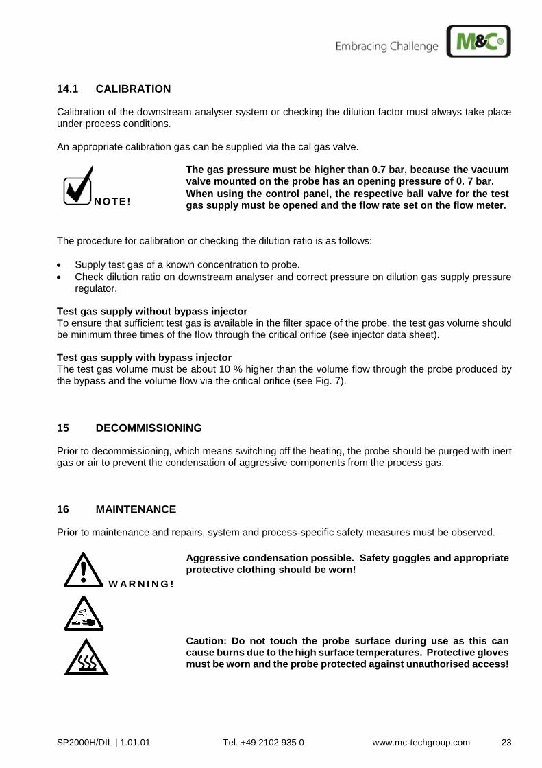
14.1 CALIBRATION
Calibration of the downstream analyser system or checking the dilution factor must always take place under process conditions. An appropriate calibration gas can be supplied via the cal gas valve.
NOTE!
The gas pressure must be higher than 0.7 bar, because the vacuum valve mounted on the probe has an opening pressure of 0. 7 bar.
When using the control panel, the respective ball valve for the test gas supply must be opened and the flow rate set on the flow meter.
The procedure for calibration or checking the dilution ratio is as follows:
Supply test gas of a known concentration to probe.
Check dilution ratio on downstream analyser and correct pressure on dilution gas supply pressure regulator.
Test gas supply without bypass injector To ensure that sufficient test gas is available in the filter space of the probe, the test gas volume should be minimum three times of the flow through the critical orifice (see injector data sheet). Test gas supply with bypass injector The test gas volume must be about 10 % higher than the volume flow through the probe produced by the bypass and the volume flow via the critical orifice (see Fig. 7).
15 DECOMMISSIONING
Prior to decommissioning, which means switching off the heating, the probe should be purged with inert gas or air to prevent the condensation of aggressive components from the process gas.
16 MAINTENANCE
Prior to maintenance and repairs, system and process-specific safety measures must be observed.
W A R N I N G !
Aggressive condensation possible. Safety goggles and appropriate protective clothing should be worn!
Caution: Do not touch the probe surface during use as this can cause burns due to the high surface temperatures. Protective gloves must be worn and the probe protected against unauthorised access!
24 SP2000H-DIL | 1.01.01 Tel. +49 2102 935 0 www.mc-techgroup.com
Before carrying out maintenance work on electrical components, the mains voltage must be disconnected in all poles. This applies simi-larly to any connected alarm and control circuits!
No recommendations for maintenance intervals can be given. Maintenance intervals must be deter-mined depending on the particular process conditions and specific application. Probe maintenance is limited mainly to replacement of the filter elements, inspection of the seals and maintenance of the dilution systems.
NOTE!
The probe does not need to be removed for repairs or maintenance. The probe will need to be removed for replacement of the process-sided sample pipe.
SP2000H/DIL | 1.01.01 Tel. +49 2102 935 0 www.mc-techgroup.com 25
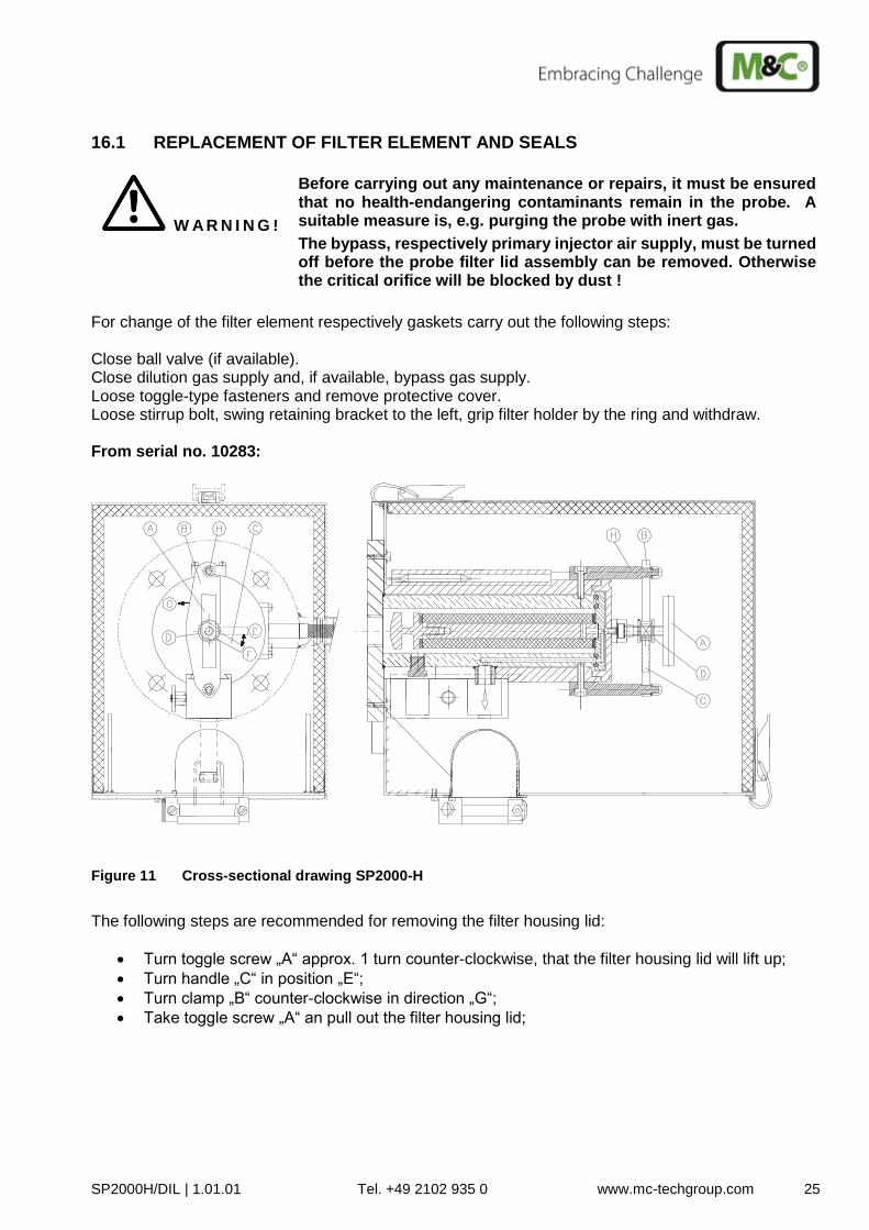
16.1 REPLACEMENT OF FILTER ELEMENT AND SEALS
W A R N I N G !
Before carrying out any maintenance or repairs, it must be ensured that no health-endangering contaminants remain in the probe. A suitable measure is, e.g. purging the probe with inert gas.
The bypass, respectively primary injector air supply, must be turned off before the probe filter lid assembly can be removed. Otherwise the critical orifice will be blocked by dust !
For change of the filter element respectively gaskets carry out the following steps: Close ball valve (if available). Close dilution gas supply and, if available, bypass gas supply. Loose toggle-type fasteners and remove protective cover. Loose stirrup bolt, swing retaining bracket to the left, grip filter holder by the ring and withdraw. From serial no. 10283:
Figure 11 Cross-sectional drawing SP2000-H
The following steps are recommended for removing the filter housing lid:
Turn toggle screw „A“ approx. 1 turn counter-clockwise, that the filter housing lid will lift up;
Turn handle „C“ in position „E“;
Turn clamp „B“ counter-clockwise in direction „G“;
Take toggle screw „A“ an pull out the filter housing lid;
26 SP2000H-DIL | 1.01.01 Tel. +49 2102 935 0 www.mc-techgroup.com
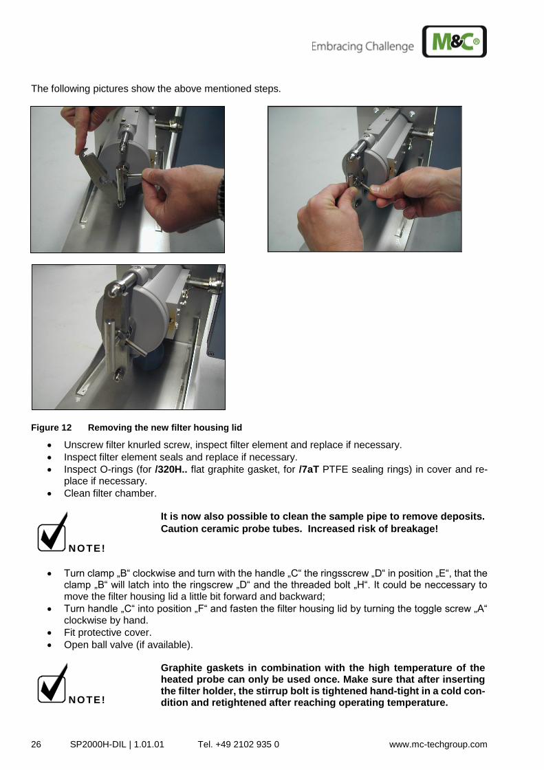
The following pictures show the above mentioned steps.
Figure 12 Removing the new filter housing lid
Unscrew filter knurled screw, inspect filter element and replace if necessary.
Inspect filter element seals and replace if necessary.
Inspect O-rings (for /320H.. flat graphite gasket, for /7aT PTFE sealing rings) in cover and re-place if necessary.
Clean filter chamber.
NOTE!
It is now also possible to clean the sample pipe to remove deposits.
Caution ceramic probe tubes. Increased risk of breakage!
Turn clamp „B“ clockwise and turn with the handle „C“ the ringsscrew „D“ in position „E“, that the clamp „B“ will latch into the ringscrew „D“ and the threaded bolt „H“. It could be neccessary to move the filter housing lid a little bit forward and backward;
Turn handle „C“ into position „F“ and fasten the filter housing lid by turning the toggle screw „A“ clockwise by hand.
Fit protective cover.
Open ball valve (if available).
NOTE!
Graphite gaskets in combination with the high temperature of the heated probe can only be used once. Make sure that after inserting the filter holder, the stirrup bolt is tightened hand-tight in a cold con-dition and retightened after reaching operating temperature.
SP2000H/DIL | 1.01.01 Tel. +49 2102 935 0 www.mc-techgroup.com 27
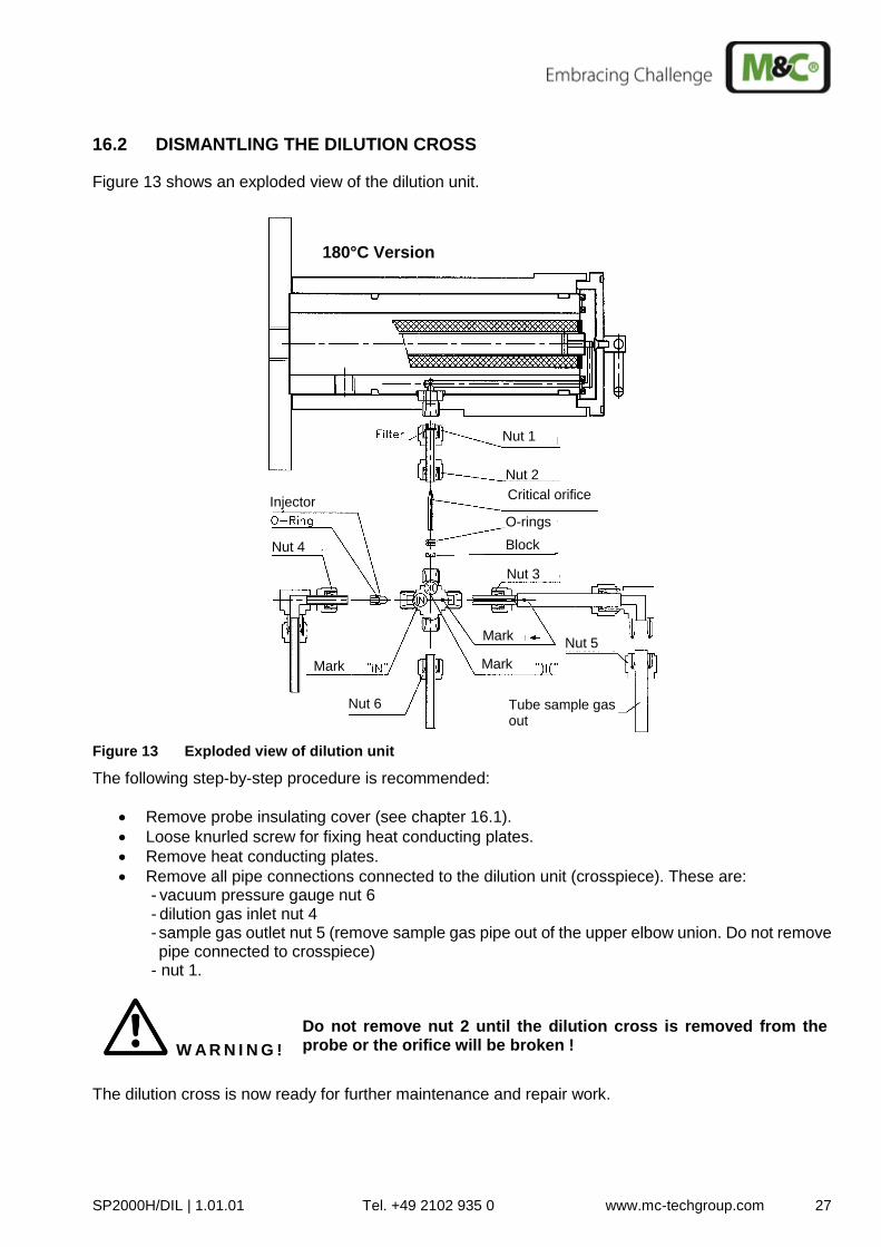
16.2 DISMANTLING THE DILUTION CROSS
Figure 13 shows an exploded view of the dilution unit.
Nut 1
Nut 2
Nut 3
Nut 4
Nut 5
Nut 6
Critical orifice
Mark
Injector
Mark
Mark
Tube sample gas out
Block
180°C Version
O-rings
Figure 13 Exploded view of dilution unit
The following step-by-step procedure is recommended:
Remove probe insulating cover (see chapter 16.1).
Loose knurled screw for fixing heat conducting plates.
Remove heat conducting plates.
Remove all pipe connections connected to the dilution unit (crosspiece). These are: - vacuum pressure gauge nut 6 - dilution gas inlet nut 4 - sample gas outlet nut 5 (remove sample gas pipe out of the upper elbow union. Do not remove pipe connected to crosspiece)
- nut 1.
W A R N I N G !
Do not remove nut 2 until the dilution cross is removed from the probe or the orifice will be broken !
The dilution cross is now ready for further maintenance and repair work.
28 SP2000H-DIL | 1.01.01 Tel. +49 2102 935 0 www.mc-techgroup.com
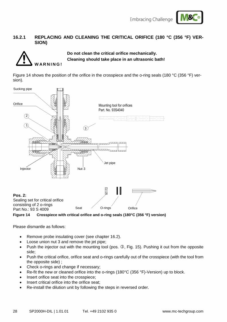
16.2.1 REPLACING AND CLEANING THE CRITICAL ORIFICE (180 °C (356 °F) VER-SION)
W A R N I N G !
Do not clean the critical orifice mechanically.
Cleaning should take place in an ultrasonic bath!
Figure 14 shows the position of the orifice in the crosspiece and the o-ring seals (180 °C (356 °F) ver-sion).
Jet pipe
2 1
Orifice
Sucking pipe
Pos. 2: Sealing set for critical orifice consisting of 2 o-rings Part No.: 93 S 4009 Orifice Seat O-rings
Mounting tool Part No.: 93S4040
3
Nut 3 Injector
Figure 14 Crosspiece with critical orifice and o-ring seals (180°C (356 °F) version)
Please dismantle as follows:
Remove probe insulating cover (see chapter 16.2).
Loose union nut 3 and remove the jet pipe;
Push the injector out with the mounting tool (pos. , Fig. 15). Pushing it out from the opposite side;
Push the critical orifice, orifice seat and o-rings carefully out of the crosspiece (with the tool from the opposite side) ;
Check o-rings and change if necessary;
Re-fit the new or cleaned orifice into the o-rings (180°C (356 °F)-Version) up to block.
Insert orifice seat into the crosspiece;
Insert critical orifice into the orifice seat;
Re-install the dilution unit by following the steps in reversed order.
SP2000H/DIL | 1.01.01 Tel. +49 2102 935 0 www.mc-techgroup.com 29
W A R N I N G !
The Swagelok® fittings must be carefully tightened to avoid damages to the internal components. Tightening too far will damage the cross.
Use a mating gauge to make sure that the fittings are not too tight.
If a fitting is believed to be leaking, do not tighten the fitting to re-move the leak. Disassemble the piece completely and reassemble it making sure that the nut is not tightened too far.
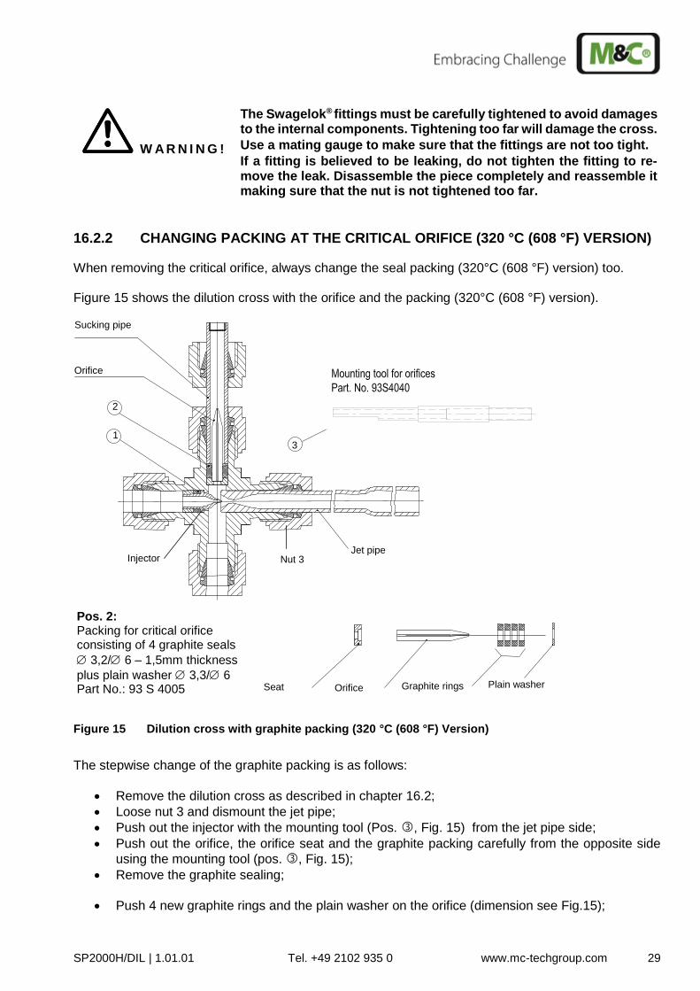
16.2.2 CHANGING PACKING AT THE CRITICAL ORIFICE (320 °C (608 °F) VERSION)
When removing the critical orifice, always change the seal packing (320°C (608 °F) version) too. Figure 15 shows the dilution cross with the orifice and the packing (320°C (608 °F) version).
Jet pipe
2 1
Orifice
Sucking pipe
Pos. 2: Packing for critical orifice consisting of 4 graphite seals
3,2/ 6 – 1,5mm thickness
plus plain washer 3,3/ 6 Part No.: 93 S 4005 Orifice Seat Graphite rings Plain washer
Mounting tool Part No.: 93S4040
3
Nut 3 Injector
Figure 15 Dilution cross with graphite packing (320 °C (608 °F) Version)
The stepwise change of the graphite packing is as follows:
Remove the dilution cross as described in chapter 16.2;
Loose nut 3 and dismount the jet pipe;
Push out the injector with the mounting tool (Pos. , Fig. 15) from the jet pipe side;
Push out the orifice, the orifice seat and the graphite packing carefully from the opposite side
using the mounting tool (pos. , Fig. 15);
Remove the graphite sealing;
Push 4 new graphite rings and the plain washer on the orifice (dimension see Fig.15);
30 SP2000H-DIL | 1.01.01 Tel. +49 2102 935 0 www.mc-techgroup.com
Place the orifice seat in the crosspiece;
Put the orifice in the seat;
Push the graphite packing with the tool into the cross up to block and press;
Re-fit the jet pipe.
W A R N I N G !
The Swagelok® fittings must be carefully tightened to avoid damages to the internal components. Tightening too far will damage the cross.
Use a mating gauge to make sure that the fittings are not too tight.
If a fitting is believed to be leaking, do not tighten the fitting to re-move the leak. Disassemble the piece completely and reassemble it making sure that the nut is not tightened too far.
16.2.3 CHANGING AND CLEANING OF THE INJECTOR NOZZLE
NOTE!
For cleaning the injector it is not necessary to remove it out of the dilution cross. Clean the nozzle mechanically. For the 180 °C (356 °F) version the complete cross can be cleaned up in an ultrasonic bath.
W A R N I N G !
The complete cross of the 320 °C (608 °F) version can not be cleaned in an ultrasonic bath. Otherwise the graphite packing will be dam-aged !
Before cleaning the nozzle with compressed air remove the critical orifice first (s. chapter 16.2.1) !
16.2.4 CHANGING O-RING AT INJECTOR NOZZLE (180 °C (356 °F) VERSION)
Please change the o-ring as following:
Loose union nut 3 and remove the jet pipe;
Loose nut 4 and remove the dilution tube connection;
Push out the injector with the tool (Pos. ) from the opposite side (jet pipe);
Remove the o-ring from the nozzle;
Push on the new o-ring onto the nozzle;
Re-install the injector with the tool. Push it up to block and press it tightly.
W A R N I N G !
The Swagelok® fittings must be carefully tightened to avoid damages to the internal components!
SP2000H/DIL | 1.01.01 Tel. +49 2102 935 0 www.mc-techgroup.com 31
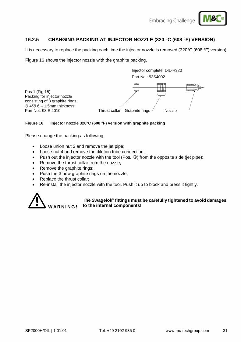
16.2.5 CHANGING PACKING AT INJECTOR NOZZLE (320 °C (608 °F) VERSION)
It is necessary to replace the packing each time the injector nozzle is removed (320°C (608 °F) version). Figure 16 shows the injector nozzle with the graphite packing.
Thrust collar Nozzle Graphite rings
Part No.: 93S4002 Injector complete, DIL-H320
Pos 1 (Fig.15): Packing for injector nozzle consisting of 3 graphite rings
4/ 6 – 1,5mm thickness Part No.: 93 S 4010
Figure 16 Injector nozzle 320°C (608 °F) version with graphite packing
Please change the packing as following:
Loose union nut 3 and remove the jet pipe;
Loose nut 4 and remove the dilution tube connection;
Push out the injector nozzle with the tool (Pos. ) from the opposite side (jet pipe);
Remove the thrust collar from the nozzle;
Remove the graphite rings;
Push the 3 new graphite rings on the nozzle;
Replace the thrust collar;
Re-install the injector nozzle with the tool. Push it up to block and press it tightly.
W A R N I N G !
The Swagelok® fittings must be carefully tightened to avoid damages to the internal components!
32 SP2000H-DIL | 1.01.01 Tel. +49 2102 935 0 www.mc-techgroup.com
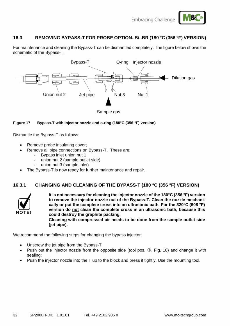
16.3 REMOVING BYPASS-T FOR PROBE OPTION..B/..BR (180 °C (356 °F) VERSION)
For maintenance and cleaning the Bypass-T can be dismantled completely. The figure below shows the schematic of the Bypass-T.
Injector nozzle O-ring Bypass-T
Jet pipe Union nut 2 Nut 1 Nut 3
Sample gas
Dilution gas
Figure 17 Bypass-T with Injector nozzle and o-ring (180°C (356 °F) version)
Dismantle the Bypass-T as follows:
Remove probe insulating cover;
Remove all pipe connections on Bypass-T. These are: - Bypass inlet union nut 1 - union nut 2 (sample outlet side) - union nut 3 (sample inlet).
The Bypass-T is now ready for further maintenance and repair.
16.3.1 CHANGING AND CLEANING OF THE BYPASS-T (180 °C (356 °F) VERSION)
NOTE!
It is not necessary for cleaning the injector nozzle of the 180°C (356 °F) version to remove the injector nozzle out of the Bypass-T. Clean the nozzle mechani-cally or put the complete cross into an ultrasonic bath. For the 320°C (608 °F) version do not clean the complete cross in an ultrasonic bath, because this could destroy the graphite packing.
Cleaning with compressed air needs to be done from the sample outlet side (jet pipe).
We recommend the following steps for changing the bypass injector:
Unscrew the jet pipe from the Bypass-T;
Push out the injector nozzle from the opposite side (tool pos. , Fig. 18) and change it with sealing;
Push the injector nozzle into the T up to the block and press it tightly. Use the mounting tool.
SP2000H/DIL | 1.01.01 Tel. +49 2102 935 0 www.mc-techgroup.com 33
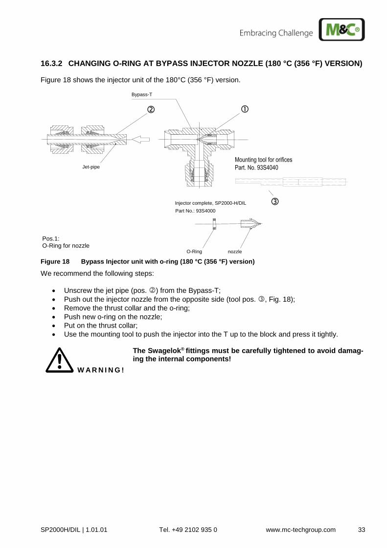
16.3.2 CHANGING O-RING AT BYPASS INJECTOR NOZZLE (180 °C (356 °F) VERSION)
Figure 18 shows the injector unit of the 180°C (356 °F) version.
nozzle O-Ring
Part No.: 93S4000 Injector complete, SP2000-H/DIL
Mounting tool Part No.: 93 S 4040
Jet-pipe
Bypass-T
Pos.1: O-Ring for nozzle
Figure 18 Bypass Injector unit with o-ring (180 °C (356 °F) version)
We recommend the following steps:
Unscrew the jet pipe (pos. ) from the Bypass-T;
Push out the injector nozzle from the opposite side (tool pos. , Fig. 18);
Remove the thrust collar and the o-ring;
Push new o-ring on the nozzle;
Put on the thrust collar;
Use the mounting tool to push the injector into the T up to the block and press it tightly.
W A R N I N G !
The Swagelok® fittings must be carefully tightened to avoid damag-ing the internal components!
34 SP2000H-DIL | 1.01.01 Tel. +49 2102 935 0 www.mc-techgroup.com
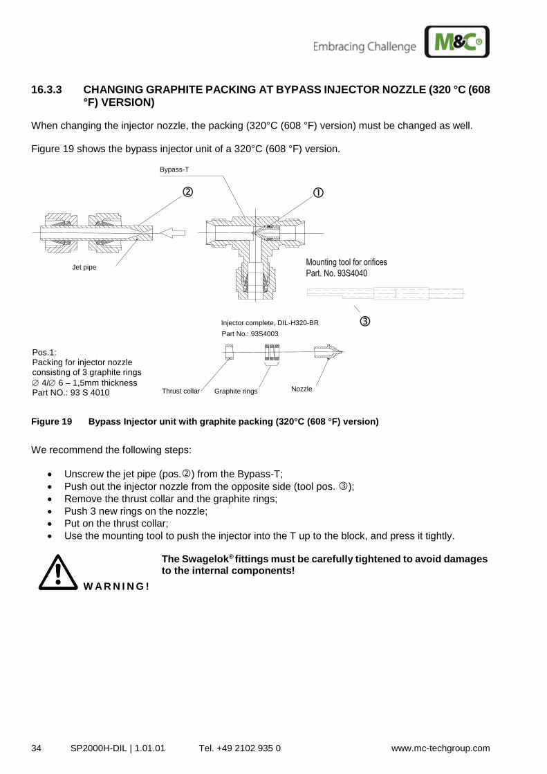
16.3.3 CHANGING GRAPHITE PACKING AT BYPASS INJECTOR NOZZLE (320 °C (608 °F) VERSION)
When changing the injector nozzle, the packing (320°C (608 °F) version) must be changed as well. Figure 19 shows the bypass injector unit of a 320°C (608 °F) version.
Thrust collar Nozzle Graphite rings
Part No.: 93S4003 Injector complete, DIL-H320-BR
Mounting tool Part No.: 93 S 4040
Jet pipe
Bypass-T
Pos.1: Packing for injector nozzle consisting of 3 graphite rings
4/ 6 – 1,5mm thickness Part NO.: 93 S 4010
Figure 19 Bypass Injector unit with graphite packing (320°C (608 °F) version)
We recommend the following steps:
Unscrew the jet pipe (pos.) from the Bypass-T;
Push out the injector nozzle from the opposite side (tool pos. );
Remove the thrust collar and the graphite rings;
Push 3 new rings on the nozzle;
Put on the thrust collar;
Use the mounting tool to push the injector into the T up to the block, and press it tightly.
W A R N I N G !
The Swagelok® fittings must be carefully tightened to avoid damages to the internal components!
SP2000H/DIL | 1.01.01 Tel. +49 2102 935 0 www.mc-techgroup.com 35
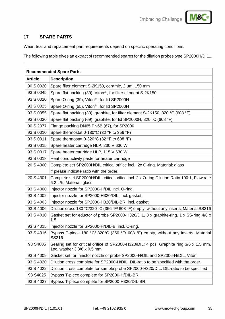
17 SPARE PARTS
Wear, tear and replacement part requirements depend on specific operating conditions. The following table gives an extract of recommended spares for the dilution probes type SP2000H/DIL... .
Recommended Spare Parts
Article Description
90 S 0020 Spare filter element S-2K150, ceramic, 2 µm, 150 mm
93 S 0045 Spare flat packing (30), Viton , for filter element S-2K150
93 S 0020 Spare O-ring (39), Viton , for lid SP2000H
93 S 0025 Spare O-ring (55), Viton , for lid SP2000H
93 S 0055 Spare flat packing (30), graphite, for filter element S-2K150, 320 °C (608 °F)
93 S 0030 Spare flat packing (69), graphite, for lid SP2000H, 320 °C (608 °F)
90 S 2077 Flange packing DN65 PN6B (67), for SP2000
93 S 0010 Spare thermostat 0-180°C (32 °F to 356 °F)
93 S 0011 Spare thermostat 0-320°C (32 °F to 608 °F)
93 S 0015 Spare heater cartridge HLP, 230 V 630 W
93 S 0017 Spare heater cartridge HLP, 115 V 630 W
93 S 0018 Heat conductivity paste for heater cartridge
20 S 4300 Complete set SP2000H/DIL critical orifice incl. 2x O-ring. Material: glass
# please indicate ratio with the order.
20 S 4301 Complete set SP2000H/DIL critical orifice incl. 2 x O-ring Dilution Ratio 100:1, Flow rate 6.2 L/h, Material: glass
93 S 4000 Injector nozzle for SP2000-H/DIL incl. O-ring.
93 S 4002 Injector nozzle for SP2000-H320/DIL, incl. gasket.
93 S 4003 Injector nozzle for SP2000-H320/DIL-BR, incl. gasket.
93 S 4006 Dilution cross 180 °C/320 °C (356 °F/ 608 °F) empty, without any inserts, Material SS316
93 S 4010 Gasket set for eductor of probe SP2000-H320/DIL, 3 x graphite-ring. 1 x SS-ring 4/6 x 1.5
93 S 4015 Injector nozzle for SP2000-H/DIL-B, incl. O-ring.
93 S 4016 Bypass T-piece 180 °C/ 320°C (356 °F/ 608 °F) empty, without any inserts, Material SS316
93 S4005 Sealing set for critical orifice of SP2000-H320/DIL: 4 pcs. Graphite ring 3/6 x 1.5 mm, 1pc. washer 3,3/6 x 0.5 mm
93 S 4009 Gasket set for injector nozzle of probe SP2000-H/DIL and SP2006-H/DIL, Viton.
93 S 4020 Dilution cross complete for SP2000-H/DIL. DIL-ratio to be specified with the order.
93 S 4022 Dilution cross complete for sample probe SP2000-H320/DIL. DIL-ratio to be specified
93 S4025 Bypass T-piece complete for SP2000-H/DIL-BR.
93 S 4027 Bypass T-piece complete for SP2000-H320/DIL-BR.

36 SP2000H-DIL | 1.01.01 Tel. +49 2102 935 0 www.mc-techgroup.com
18 APPENDIX
More product documentation is available on our Internet catalogue: www.mc-techgroup.com.