Embed Size (px)
Citation preview
8/13/2019 SP 15A Manual
http://slidepdf.com/reader/full/sp-15a-manual 1/15
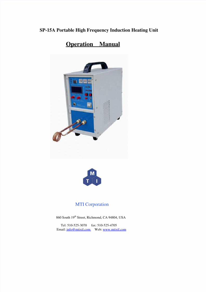
SP-15A Portable High Frequency Induction Heating Unit
Operation Manual
MTI Corporation
860 South 19th Street, Richmond, CA 94804, USA
Tel: 510-525-3070 fax: 510-525-4705
Email: [email protected] Web: www.mtixtl.com
8/13/2019 SP 15A Manual
http://slidepdf.com/reader/full/sp-15a-manual 2/15
Content
1. Introduction: .......................................................................................................................... 31.1 Applications:............................................................................................................................................3
1.2 Features of SP-15 series:........................................................................................................................3
2. Specification .......................................................................................................................... 33. Front Panel ............................................................................................................................4
3.1 LED....................................................................................................................................................5
3.2 Button.................................................................................................................................................5
3.3 Knob...................................................................................................................................................6
3.4 Display ...............................................................................................................................................6
3.5 Time preset.........................................................................................................................................6
3.6 Remote control socket........................................................................................................................6
3.7 Switch ................................................................................................................................................6
4. Back Panel ............................................................................................................................74.1 Main Power switch ............................................................................................................................7
4.2 Control power switch.........................................................................................................................7
4.3 Grounding ..........................................................................................................................................7
5. Installation .............................................................................................................................75.1 Cooling water......................................................................................................................................7
5.2 Grounding ..........................................................................................................................................9
5.3 Install the induction coil.....................................................................................................................9
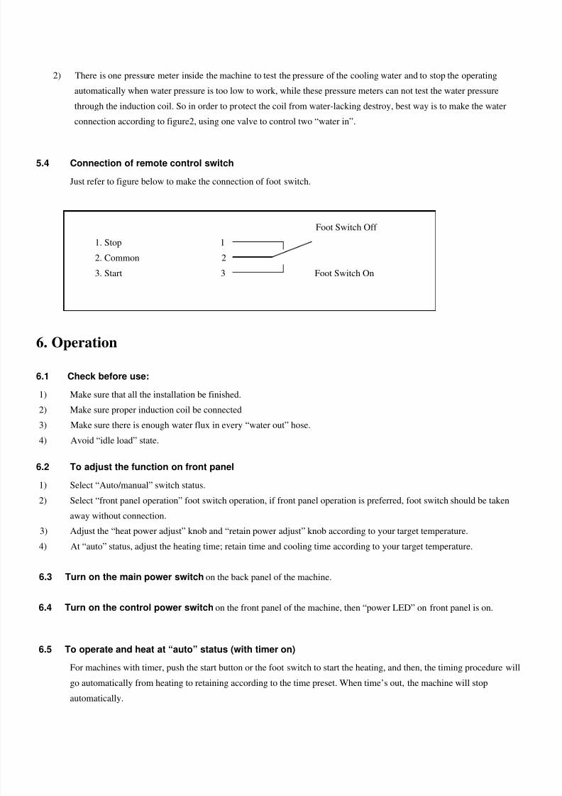
5.4 Connection of remote control switch...............................................................................................10
6. Operation .............................................................................................................................106.1 Check before use................................................................................................................................10
6.2 To adjust the function on front panel.................................................................................................10
6.3 Turn on the main power switch .........................................................................................................10
6.4 Turn on the control power switch ......................................................................................................10
6.5 To operate and heat at “auto” status (with timer on) .........................................................................10
6.6 To operate and heat at “manual” status..............................................................................................11
6.7 To turn off ..........................................................................................................................................11
7. Troubleshooting…………………………………………………………………………12
Design and manufacture of inductorium ................................................................................. 13
Product Details ........................................................................................................................ 15
Notice Before Using
1. Make sure to use soft and pure water, and its temperature should be lower than 40oC (104
oF).
2. The induction coil is very important to heating efficiency, so please consult us if you have any questionsof designing your own induction coil.
8/13/2019 SP 15A Manual
http://slidepdf.com/reader/full/sp-15a-manual 3/15
1. Introduction:
SP-15A is a kind of high frequency heating equipment, which features the latest inverting technology so as to make itself
light and convenient.
1.1 Applications:
1.1.1 Soldering of diamond impregnated cutting and grinding tools which includes:
a. segmented diamond saw blade from 250-2500mm diameter
b. thin-wall diamond impregnated bit
c. diamond impregnated grinding disk
d. diamond impregnated tube, etc.
1.1.2 Soldering or brazing of cutting and drilling tools, etc.
1.1.3 Heating treatment of metal parts
1.1.4 Melting metal materials
1.2 Features of SP-15 series:
a. Quite light and portable
b. High heating speed, like segmented diamond cutting disk of 1600 diameter— less than 10 seconds for soldering in one
segment
c. High duty cycle—less than 80% even in summer time, to work continuously
d. Easy installation
f. Power saved
g. Flexible coil with great function
2. Specification
Model SP-15A
Input voltage 220V single phase
Input voltage range 180-245V
Maximum oscillate power 15KVA
Duty cycle 80%
Output oscillate frequency 30-100KHz
Heat oscillate current 200-600A
8/13/2019 SP 15A Manual
http://slidepdf.com/reader/full/sp-15a-manual 4/15
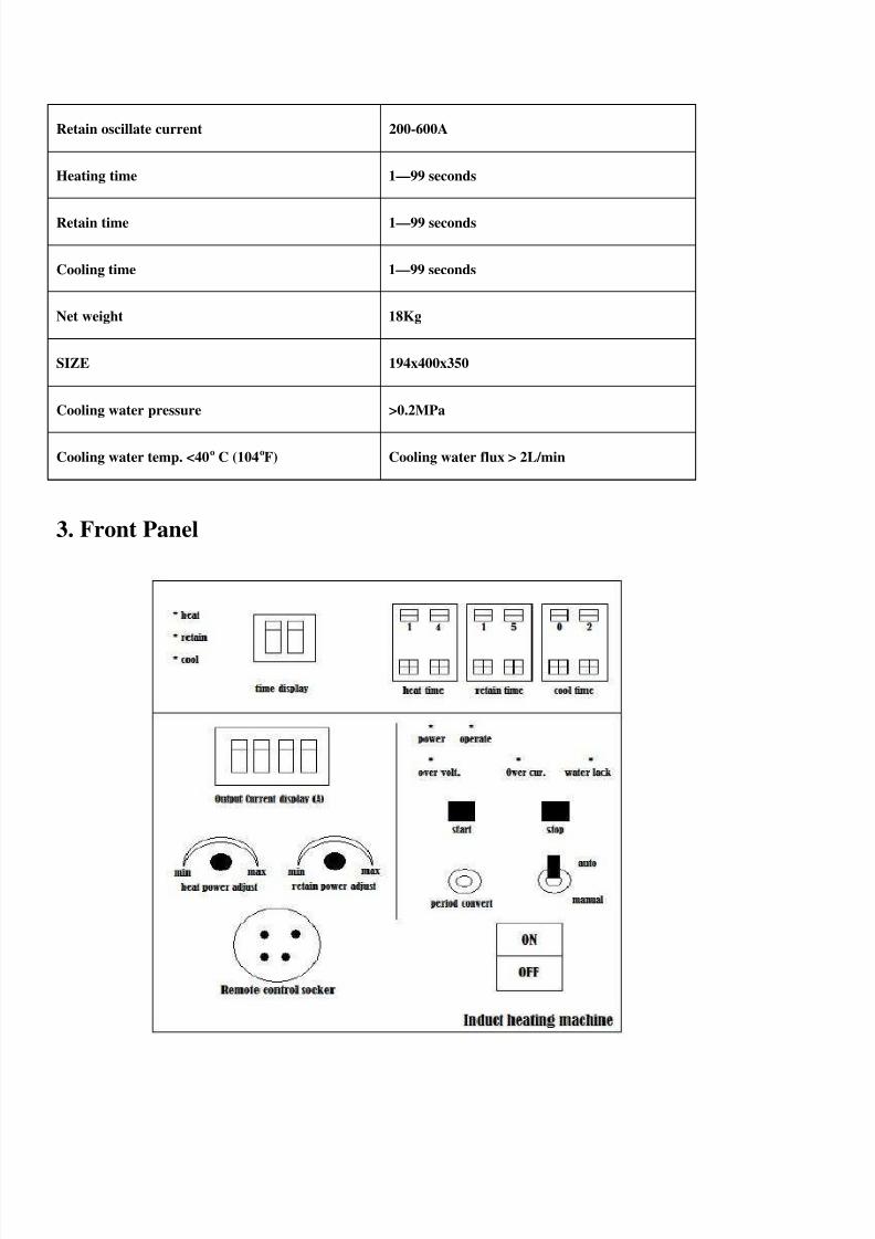
Retain oscillate current 200-600A
Heating time 1—99 seconds
Retain time 1—99 seconds
Cooling time 1—99 seconds
Net weight 18Kg
SIZE 194x400x350
Cooling water pressure >0.2MPa
Cooling water temp. <40o C (104oF) Cooling water flux > 2L/min
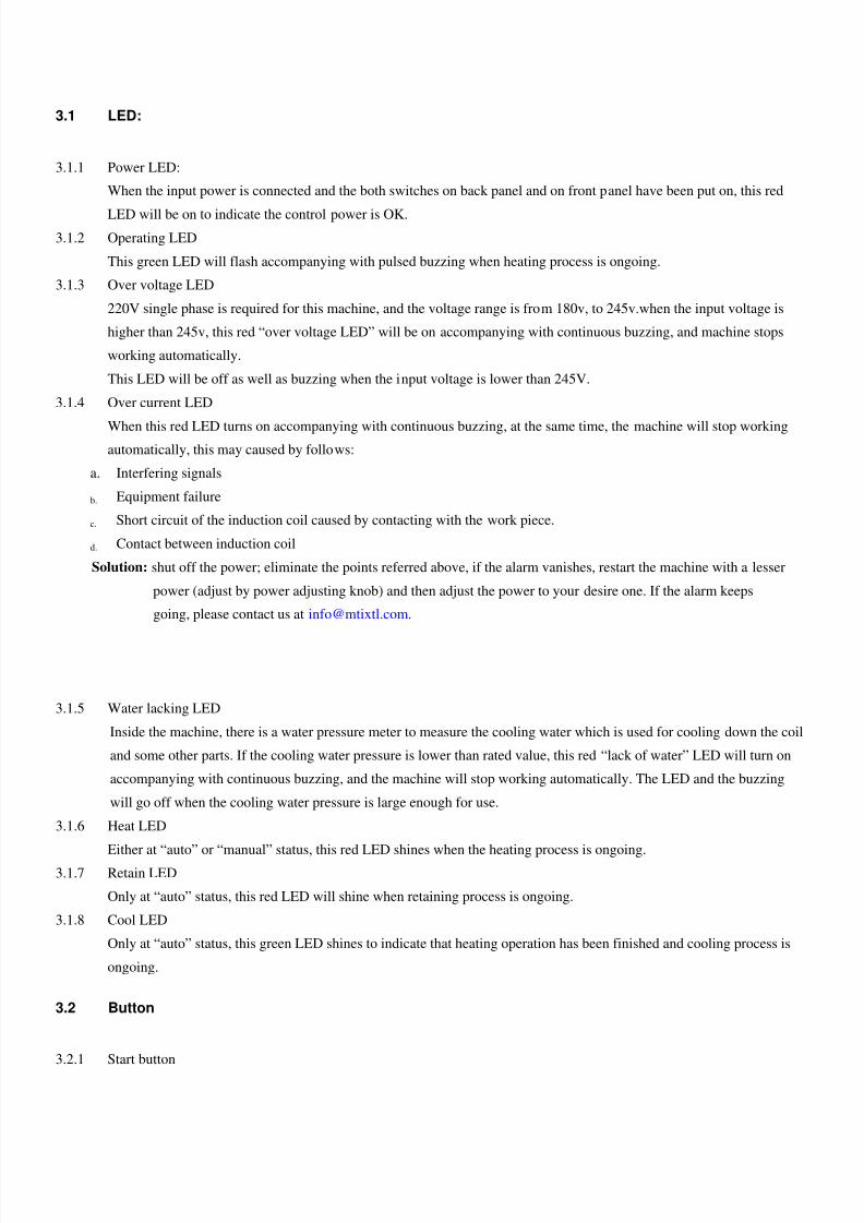
3. Front Panel
8/13/2019 SP 15A Manual
http://slidepdf.com/reader/full/sp-15a-manual 5/15
3.1 LED:
3.1.1 Power LED:
When the input power is connected and the both switches on back panel and on front panel have been put on, this red
LED will be on to indicate the control power is OK.
3.1.2 Operating LED
This green LED will flash accompanying with pulsed buzzing when heating process is ongoing.
3.1.3 Over voltage LED
220V single phase is required for this machine, and the voltage range is from 180v, to 245v.when the input voltage is
higher than 245v, this red “over voltage LED” will be on accompanying with continuous buzzing, and machine stops
working automatically.
This LED will be off as well as buzzing when the input voltage is lower than 245V.
3.1.4 Over current LED
When this red LED turns on accompanying with continuous buzzing, at the same time, the machine will stop workingautomatically, this may caused by follows:
a. Interfering signals
b. Equipment failure
c. Short circuit of the induction coil caused by contacting with the work piece.
d. Contact between induction coil
Solution: shut off the power; eliminate the points referred above, if the alarm vanishes, restart the machine with a lesser
power (adjust by power adjusting knob) and then adjust the power to your desire one. If the alarm keeps
going, please contact us at [email protected].
3.1.5 Water lacking LED
Inside the machine, there is a water pressure meter to measure the cooling water which is used for cooling down the coil
and some other parts. If the cooling water pressure is lower than rated value, this red “lack of water” LED will turn on
accompanying with continuous buzzing, and the machine will stop working automatically. The LED and the buzzing
will go off when the cooling water pressure is large enough for use.
3.1.6 Heat LED
Either at “auto” or “manual” status, this red LED shines when the heating process is ongoing.
3.1.7 Retain LED
Only at “auto” status, this red LED will shine when retaining process is ongoing.
3.1.8 Cool LED
Only at “auto” status, this green LED shines to indicate that heating operation has been finished and cooling process is
ongoing.
3.2 Button
3.2.1 Start button
8/13/2019 SP 15A Manual
http://slidepdf.com/reader/full/sp-15a-manual 6/15
Press this button to start the induction heating process both at “auto” and “manual” status, but if foot switch or remote
control switch with “normal open” and “normal close” contact, is connected by “remote socket” to machine, the “start
button” will be invalid, instead the foot switch or other remote control switch can be used to start the operation of the
machine.
3.2.2 Stop buttonPress to stop any operation of this machine
3.2.3 Period Convert button
This button is only valid at “auto” status. At “auto” status, the three periods of heating, retaining and cooling will be
processed automatically according to the time adjusted, but any push of the “period convert button” will convert the
period to the next at once.
3.3 Knob
3.3.1 Heating Power Adjust Knob
This knob can be turned to adjust the heating power of the machine to control the heating speed.
3.1.2 Retaining Power Adjust Knob
This knob is only valid at “auto” status to adjust the retaining power of the machine.
3.4 Display
3.4.1 Current display
This “display” will show the output current of the machine.
3.4.2 Time display
At “manual” status, this “time display” will show out the heating time; at “auto” status, this “time display” will show out
the heating time, retaining time and cooling time correspondingly.
3.5 Time preset
To set the heating time, retaining time and cooling time from 1~99 seconds orderly.
3.6 Remote control socket
By this socket, foot control switch or remote control box or other remote control can be connected to control the start and
stop of the machine.
3.7 Switch
3.7.1 Control Power Switch
This switch functions to turn on or off the control power of the heating machine.
3.7.2 Auto/manual select switch
8/13/2019 SP 15A Manual
http://slidepdf.com/reader/full/sp-15a-manual 7/15
This switch selects the status of time control function. Once start the heating in “auto” status, the machine will process
automatically according to the preset heating power, retaining power, heating time, retaining time and cooling time.
When select “manual” status, the time controller will be invalid, and the operator will start or stop the heating process
manually.
4. Back Panel
4.1 Main Power switch
To switch on or off the power supply of the machine.
4.2 Control power switch
1A fuse protects the control circuit of the machine.
4.3 Grounding
Proper grounding of the machine should always be done to ensure the safety, it is suggested that 2.5MM2 Copper wire
be used for grounding.
5. Installation
5.1 Cooling water
5.1.1 Standard of water
Proper Cooling water is very important for the effective use of induction heating machine, so pure and clean water is
required, but if the water property is not satisfied, or the water resistance is very small, there will be a great danger
caused by electricity, so, please follow the standard:
•Flux of the cooling water: ≥ 6L/min
•Cooling water pressure: ≥0.2 Mpa
•Temperature of the Cooling water: <40o C
•Cooling water purity desire:PH: 7.0~9.0
Chloride composition<20ppm
Nitrate composition <10PPm
Calcium carbonation<250PPm
Resistivity (Under 25oC)>2500ohm/cm
Total impurity composition<250PPm
Non depositing temperature of impurities: <57 o
C
5.1.2 Cooling water suggested
Following water can all be used as cooling water. But priority is from left to right:
8/13/2019 SP 15A Manual
http://slidepdf.com/reader/full/sp-15a-manual 8/15
Distilled water—Soft water—Pure water—Filtrated water supply
5.1.3 Cooling water forbidden
Sea water, unstrained water from river and well.
5.1.4 Suggested cooling water system
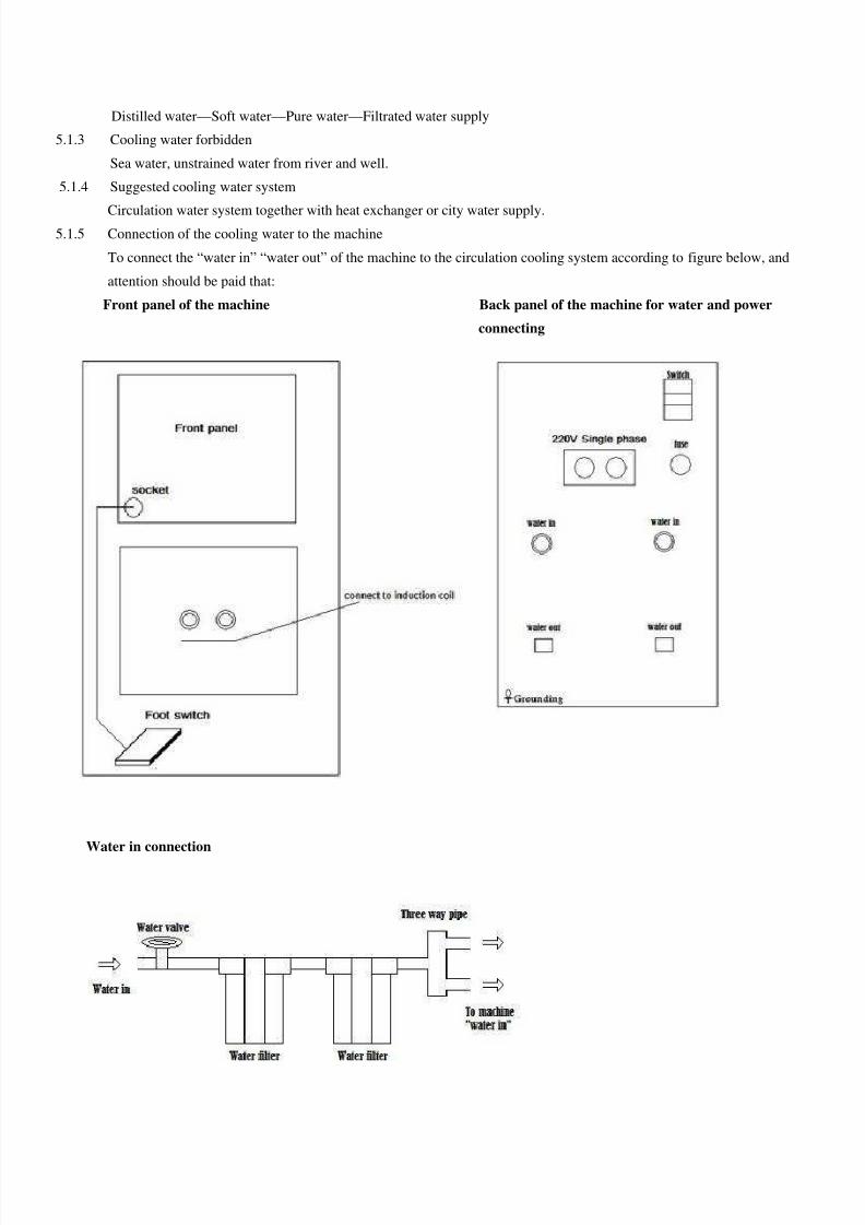
Circulation water system together with heat exchanger or city water supply. 5.1.5 Connection of the cooling water to the machine
To connect the “water in” “water out” of the machine to the circulation cooling system according to figure below, and
attention should be paid that:
Front panel of the machine Back panel of the machine for water and power
connecting
Water in connection
8/13/2019 SP 15A Manual
http://slidepdf.com/reader/full/sp-15a-manual 9/15
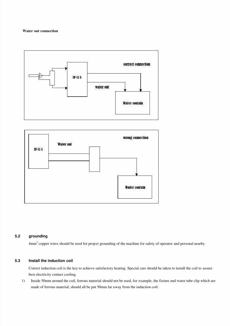
Water out connection
5.2 grounding
4mm2 copper wires should be used for proper grounding of the machine for safety of operator and personal nearby.
5.3 Install the induction coil
Correct induction coil is the key to achieve satisfactory heating. Special care should be taken to install the coil to assure
best electricity contact cooling.
1) Inside 50mm around the coil, ferrous material should not be used, for example, the fixture and water tube clip which are
made of ferrous material, should all be put 50mm far away from the induction coil.
8/13/2019 SP 15A Manual
http://slidepdf.com/reader/full/sp-15a-manual 10/15
8/13/2019 SP 15A Manual
http://slidepdf.com/reader/full/sp-15a-manual 11/15
Points should be mentioned that:
1) To push the “stop” button on front panel can stop the operation of the machine at any time.
2) If “start” button or foot switch is pressed when operation is still ongoing, the timing may go wrong,
3) “Start” button on front panel will be invalid when foot switch is used.
6.6 To operate and heat at “manual” status
Push “start” button on the front panel or hold the “foot switch” to start the machine, then the “operate LED” begins to
flash, the “time display” counts the accrual heating time with “heat LED” shining and the digital meter shows the heating
current or heating power which is preset by the “heat power adjust” knob; either “stop” button on front panel or the “foot
switch” releasing will stop the heating (“start” button on front panel will be invalid when foot switch is used).
6.7 To turn off
1) Turn off the control power switch on the front panel.
2) Turn off the main power switch on the hack panel of main part of the machine.
3) Turn off the power switch of input power.
4) Turn off the water valve.
7. Trouble Shooting
7.1 Attention for trouble shooting
1) The customer should be advised to have professional technician do the trouble shooting, or, damage may happen to both
people and the machine.
2) If there is any uncertainty about the trouble shooting, please contact us at [email protected]
7.2 Ease the trouble shooting before checking
1) Take off the foot switch or other remote control, only use the button on the front panel to operate and needless to hold the
button for long.
2) For the machine with timer, please change to “manual” state.
3) Minimize the current and power by adjust knob.
7.3 Normal phenomena for machine
1) When the load is heavy, the actual power or current may decrease or can not reach the presetting value, and the heavier the
load, the more the current decreasing;
The trouble shooting below is a reference for the customer:
8/13/2019 SP 15A Manual
http://slidepdf.com/reader/full/sp-15a-manual 12/15
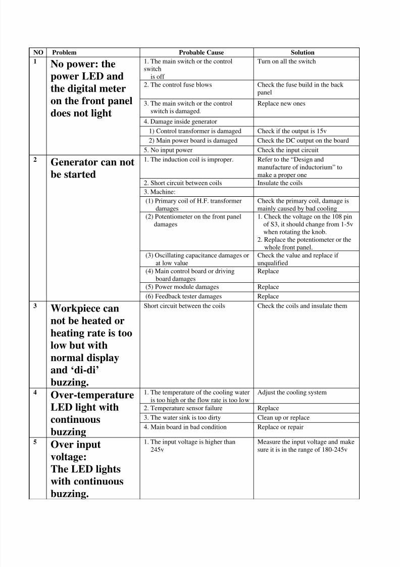
NO Problem Probable Cause Solution
1. The main switch or the controlswitch
is off
Turn on all the switch
2. The control fuse blows Check the fuse build in the back
panel
3. The main switch or the control
switch is damaged.
Replace new ones
4. Damage inside generator
1) Control transformer is damaged Check if the output is 15v
2) Main power board is damaged Check the DC output on the board
1 No power: the
power LED and
the digital meter
on the front paneldoes not light
5. No input power Check the input circuit
1. The induction coil is improper. Refer to the “Design and
manufacture of inductorium” to
make a proper one
2. Short circuit between coils Insulate the coils
3. Machine:
(1) Primary coil of H.F. transformerdamages
Check the primary coil, damage ismainly caused by bad cooling
(2) Potentiometer on the front panel
damages
1. Check the voltage on the 108 pin
of S3, it should change from 1-5v
when rotating the knob.
2. Replace the potentiometer or the
whole front panel.
(3) Oscillating capacitance damages or
at low value
Check the value and replace if
unqualified
(4) Main control board or driving
board damages
Replace
(5) Power module damages Replace
2 Generator can not
be started
(6) Feedback tester damages Replace3 Workpiece can
not be heated or
heating rate is too
low but with
normal display
and ‘di-di’
buzzing.
Short circuit between the coils Check the coils and insulate them
1. The temperature of the cooling water
is too high or the flow rate is too low
Adjust the cooling system
2. Temperature sensor failure Replace
3. The water sink is too dirty Clean up or replace
4
Over-temperatureLED light with
continuous
buzzing4. Main board in bad condition Replace or repair
5 Over input
voltage:
The LED lights
with continuous
buzzing.
1. The input voltage is higher than
245v
Measure the input voltage and make
sure it is in the range of 180-245v

8/13/2019 SP 15A Manual
http://slidepdf.com/reader/full/sp-15a-manual 13/15
2. Potentiometer presetting on the main
board is not correct
Reset the value for over input
voltage control by adjusting the
potentiometer
3. Main control board damages Replace
8/13/2019 SP 15A Manual
http://slidepdf.com/reader/full/sp-15a-manual 14/15
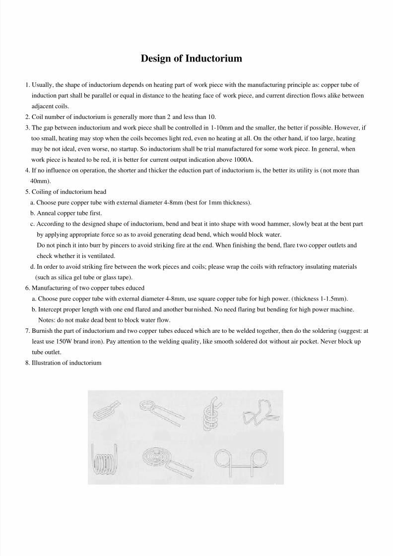
Design of Inductorium
1. Usually, the shape of inductorium depends on heating part of work piece with the manufacturing principle as: copper tube of
induction part shall be parallel or equal in distance to the heating face of work piece, and current direction flows alike betweenadjacent coils.
2. Coil number of inductorium is generally more than 2 and less than 10.
3. The gap between inductorium and work piece shall be controlled in 1-10mm and the smaller, the better if possible. However, if
too small, heating may stop when the coils becomes light red, even no heating at all. On the other hand, if too large, heating
may be not ideal, even worse, no startup. So inductorium shall be trial manufactured for some work piece. In general, when
work piece is heated to be red, it is better for current output indication above 1000A.
4. If no influence on operation, the shorter and thicker the eduction part of inductorium is, the better its utility is (not more than
40mm).
5. Coiling of inductorium heada. Choose pure copper tube with external diameter 4-8mm (best for 1mm thickness).
b. Anneal copper tube first.
c. According to the designed shape of inductorium, bend and beat it into shape with wood hammer, slowly beat at the bent part
by applying appropriate force so as to avoid generating dead bend, which would block water.
Do not pinch it into burr by pincers to avoid striking fire at the end. When finishing the bend, flare two copper outlets and
check whether it is ventilated.
d. In order to avoid striking fire between the work pieces and coils; please wrap the coils with refractory insulating materials
(such as silica gel tube or glass tape).
6. Manufacturing of two copper tubes educed
a. Choose pure copper tube with external diameter 4-8mm, use square copper tube for high power. (thickness 1-1.5mm).
b. Intercept proper length with one end flared and another burnished. No need flaring but bending for high power machine.
Notes: do not make dead bent to block water flow.
7. Burnish the part of inductorium and two copper tubes educed which are to be welded together, then do the soldering (suggest: at
least use 150W brand iron). Pay attention to the welding quality, like smooth soldered dot without air pocket. Never block up
tube outlet.
8. Illustration of inductorium
8/13/2019 SP 15A Manual
http://slidepdf.com/reader/full/sp-15a-manual 15/15
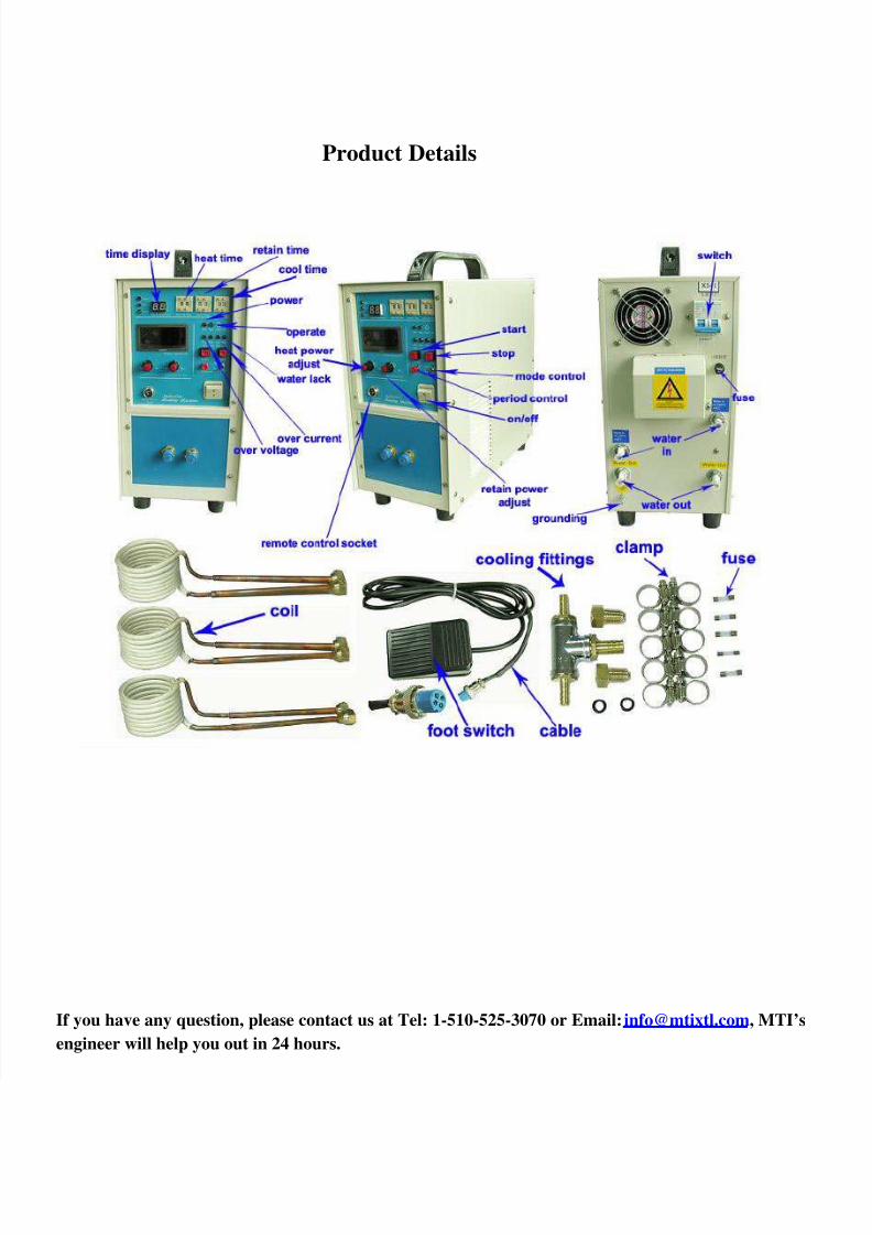
Product Details
If you have any question, please contact us at Tel: 1-510-525-3070 or Email: [email protected], MTI’s
engineer will help you out in 24 hours.