Embed Size (px)
Citation preview
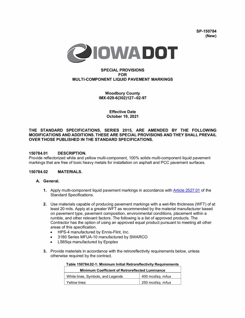
SP-150784 (New)
SPECIAL PROVISIONS FOR
MULTI-COMPONENT LIQUID PAVEMENT MARKINGS
Woodbury County IMX-029-6(302)127--02-97
Effective Date October 19, 2021
THE STANDARD SPECIFICATIONS, SERIES 2015, ARE AMENDED BY THE FOLLOWING MODIFICATIONS AND ADDITIONS. THESE ARE SPECIAL PROVISIONS AND THEY SHALL PREVAIL OVER THOSE PUBLISHED IN THE STANDARD SPECIFICATIONS. 150784.01 DESCRIPTION. Provide reflectorized white and yellow multi-component, 100% solids multi-component liquid pavement markings that are free of toxic heavy metals for installation on asphalt and PCC pavement surfaces. 150784.02 MATERIALS.
A. General. 1. Apply multi-component liquid pavement markings in accordance with Article 2527.01 of the
Standard Specifications.
2. Use materials capable of producing pavement markings with a wet-film thickness (WFT) of at least 20 mils. Apply at a greater WFT as recommended by the material manufacturer based on pavement type, pavement composition, environmental conditions, placement within a rumble, and other relevant factors. The following is a list of approved products. The Contractor has the option of using an approved equal product pursuant to meeting all other areas of this specification. • HPS-4 manufactured by Ennis-Flint, Inc. • 3180 Series MFUA-10 manufactured by SWARCO • LS65qs manufactured by Epoplex
3. Provide materials in accordance with the retroreflectivity requirements below, unless otherwise required by the contract.
Table 150784.02-1: Minimum Initial Retroreflectivity Requirements
Minimum Coefficient of Retroreflected Luminance White lines, Symbols, and Legends 400 mcd/sq. m/lux Yellow lines 250 mcd/sq. m/lux
SP-150784, Page 2 of 17
4. Provide yellow markings distinguishable from white markings in the dark.
5. The Department will not require the mixing of individual components before use if stored for no greater than 12 months.
B. Multi-Component Liquid Material.
1. Provide multi-component liquid material meeting the following requirements and
characteristics: a. Composed only of multi-component liquids and pigments, b. Does not emit or leach solvents into the environment upon application to a pavement
surface, c. The infrared spectrum for all components shall match the reference sample provided by
the manufacturer for the product tested and approved by the Department, d. Free of lead, cadmium, mercury, hexavalent chromium and other toxic heavy metals as
defined by the EPA, e. White material no darker than or no yellower than 17778 of Federal Standard Number
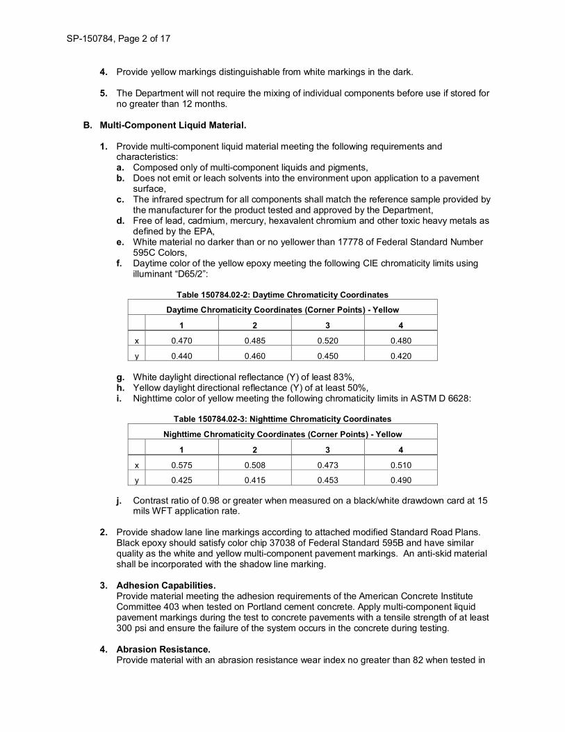
595C Colors, f. Daytime color of the yellow epoxy meeting the following CIE chromaticity limits using
illuminant “D65/2”:
Table 150784.02-2: Daytime Chromaticity Coordinates
Daytime Chromaticity Coordinates (Corner Points) - Yellow
1 2 3 4
x 0.470 0.485 0.520 0.480
y 0.440 0.460 0.450 0.420
g. White daylight directional reflectance (Y) of least 83%, h. Yellow daylight directional reflectance (Y) of at least 50%, i. Nighttime color of yellow meeting the following chromaticity limits in ASTM D 6628:
Table 150784.02-3: Nighttime Chromaticity Coordinates
Nighttime Chromaticity Coordinates (Corner Points) - Yellow
1 2 3 4
x 0.575 0.508 0.473 0.510
y 0.425 0.415 0.453 0.490
j. Contrast ratio of 0.98 or greater when measured on a black/white drawdown card at 15 mils WFT application rate.
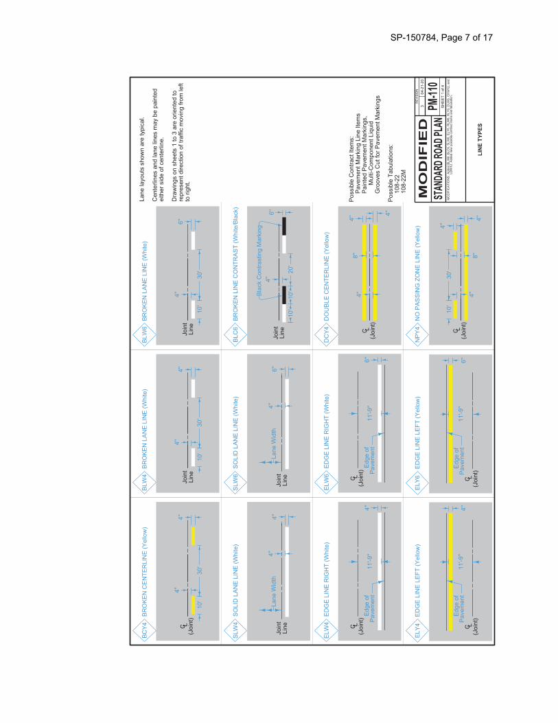
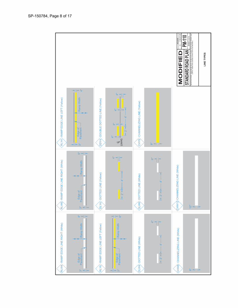
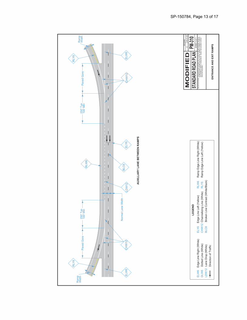
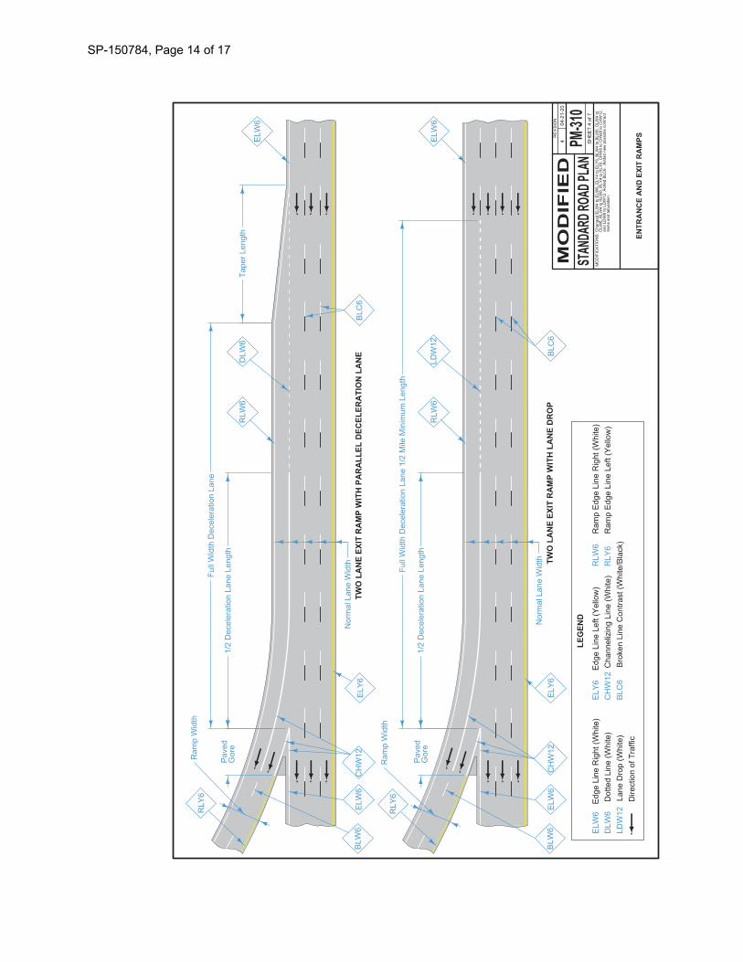
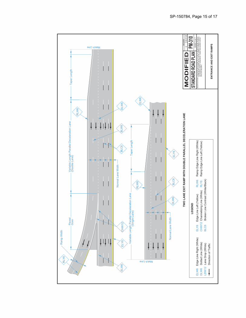
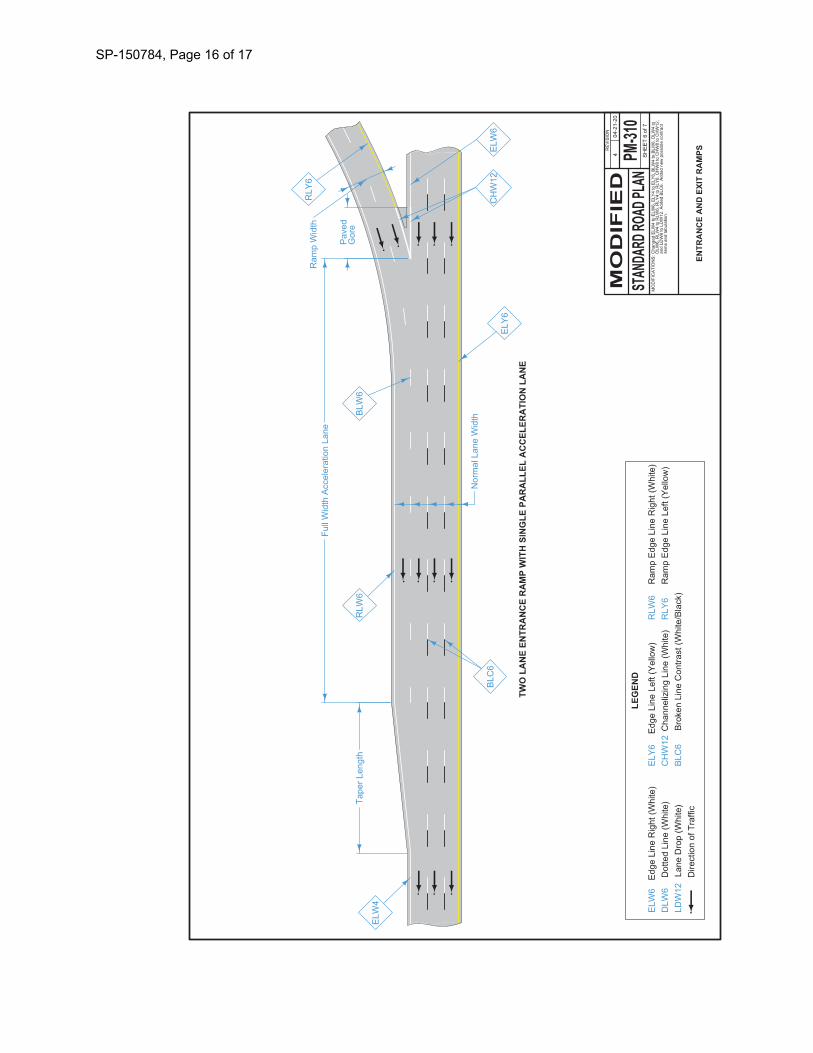
2. Provide shadow lane line markings according to attached modified Standard Road Plans. Black epoxy should satisfy color chip 37038 of Federal Standard 595B and have similar quality as the white and yellow multi-component pavement markings. An anti-skid material shall be incorporated with the shadow line marking.
3. Adhesion Capabilities. Provide material meeting the adhesion requirements of the American Concrete Institute Committee 403 when tested on Portland cement concrete. Apply multi-component liquid pavement markings during the test to concrete pavements with a tensile strength of at least 300 psi and ensure the failure of the system occurs in the concrete during testing.
4. Abrasion Resistance. Provide material with an abrasion resistance wear index no greater than 82 when tested in
SP-150784, Page 3 of 17
accordance with ASTM C 501 with a CS 17 wheel under a load of 1000 g for 1000 cycles. The Department defines the wear index as the weight in milligrams of material abraded from the sample under the test conditions.
5. Hardness.
Provide material with a Type D durometer hardness from 75 to 90 when tested in accordance with ASTM D 2240 after curing for 72 hours at 73°F ±4°F.
6. Tensile Strength. For epoxy-amine based multicomponent systems, including variations of this base chemistry, provide material with a tensile strength of at least 6000 psi when tested in accordance with ASTM D 638 after curing for 72 hours at 73°F ±4°F. For polyurea based multicomponent systems provide material with a tensile strength of at least 3000 psi when tested in accordance with ASTM D 638 after curing for 72 hours at 73°F ±4°F.
7. Compressive Strength. For epoxy-amine based multicomponent systems, including variations of this base chemistry, provide material with a compressive strength of at least 12,000 psi when tested in accordance with ASTM D 695 after curing for 72 hours at 73°F ±4°F.
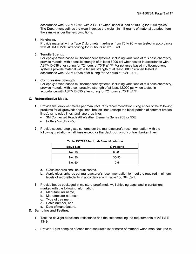
C. Retroreflective Media. 1. Provide first drop wet media per manufacturer’s recommendation using either of the following
products for all grooved: edge lines, broken lines (except the black portion of contrast broken lines), ramp edge lines, and lane drop lines: • 3M Connected Roads All Weather Elements Series 70E or 50E • Potters VisiUltra 455
2. Provide second drop glass spheres per the manufacturer’s recommendation with the
following gradation on all lines except for the black portion of contrast broken lines:
Table 150784.02-4: Utah Blend Gradation
Sieve Size % Passing
No. 18 65-80
No. 30 30-50
No. 50 0-5
a. Glass spheres shall be dual coated. b. Apply glass spheres per manufacturer’s recommendation to meet the required minimum
levels of retroreflectivity in accordance with Table 150784.02-1.
3. Provide beads packaged in moisture-proof, multi-wall shipping bags, and in containers marked with the following information: a. Manufacturer name, b. Manufacturer address, c. Type of treatment, d. Batch number, and e. Date of manufacture.
D. Sampling and Testing. 1. Test the daylight directional reflectance and the color meeting the requirements of ASTM E
1349.
2. Provide 1 pint samples of each manufacturer’s lot or batch of material when manufactured to
SP-150784, Page 4 of 17
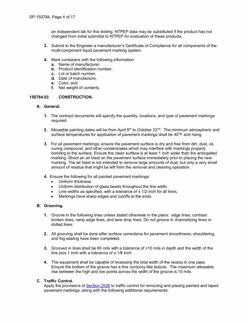
an independent lab for this testing. NTPEP data may be substituted if the product has not changed from initial submittal to NTPEP for evaluation of these products.
3. Submit to the Engineer a manufacturer’s Certificate of Compliance for all components of the
multi-component liquid pavement marking system.
4. Mark containers with the following information: a. Name of manufacturer, b. Product identification number, c. Lot or batch number, d. Date of manufacture, e. Color, and f. Net weight of contents.
150784.03 CONSTRUCTION.
A. General.
1. The contract documents will specify the quantity, locations, and type of pavement markings required.
2. Allowable painting dates will be from April 8th to October 22nd. The minimum atmospheric and
surface temperatures for application of pavement markings shall be 40°F and rising. 3. For all pavement markings, ensure the pavement surface is dry and free from dirt, dust, oil,
curing compound, and other contaminates which may interfere with markings properly bonding to the surface. Ensure the clean surface is at least 1 inch wider than the anticipated marking. Shoot an air blast on the pavement surface immediately prior to placing the new marking. The air blast is not intended to remove large amounts of dust, but only a very small amount of residue that might be left from the removal and cleaning operation.
4. Ensure the following for all painted pavement markings:
• Uniform thickness • Uniform distribution of glass beads throughout the line width, • Line widths as specified, with a tolerance of ± 1/2 inch for all lines, • Markings have sharp edges and cutoffs at the ends.
B. Grooving.
1. Groove in the following lines unless stated otherwise in the plans: edge lines, contrast
broken lines, ramp edge lines, and lane drop lines. Do not groove in channelizing lines or dotted lines.
2. All grooving shall be done after surface corrections for pavement smoothness, shouldering, and fog sealing have been completed.
3. Grooved in lines shall be 80 mils with a tolerance of +10 mils in depth and the width of the
line plus 1 inch with a tolerance of ± 1/8 inch.
4. The equipment shall be capable of recessing the total width of the recess in one pass. Ensure the bottom of the groove has a fine corduroy-like texture. The maximum allowable rise between the high and low points across the width of the groove is 10 mils.
C. Traffic Control. Apply the provisions of Section 2528 to traffic control for removing and placing painted and taped pavement markings, along with the following additional requirements:
SP-150784, Page 5 of 17
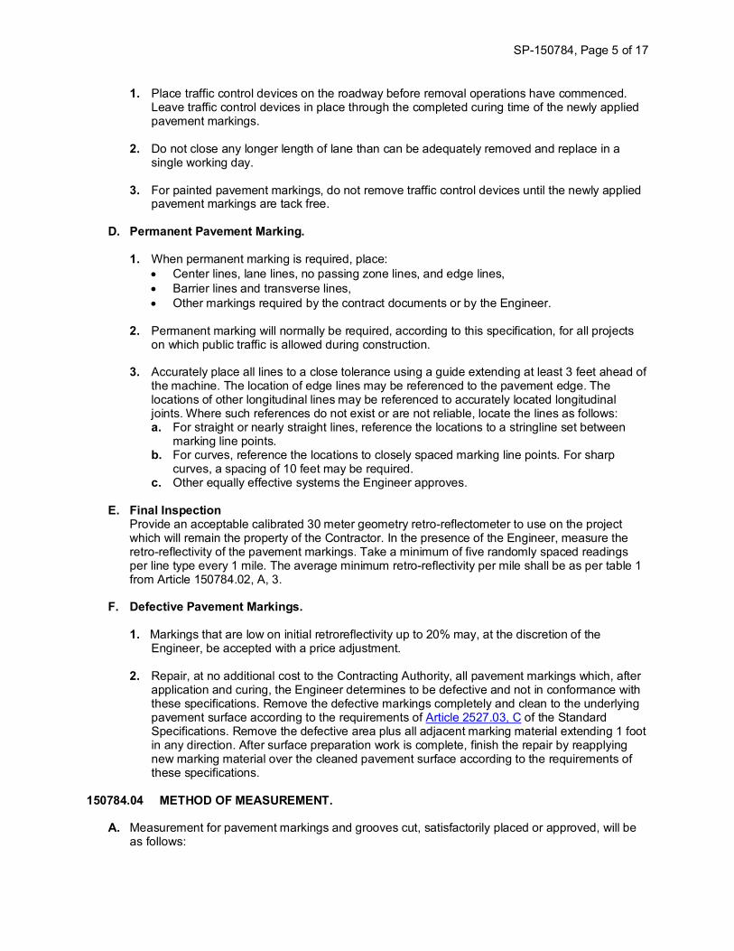
1. Place traffic control devices on the roadway before removal operations have commenced. Leave traffic control devices in place through the completed curing time of the newly applied pavement markings.
2. Do not close any longer length of lane than can be adequately removed and replace in a single working day.
3. For painted pavement markings, do not remove traffic control devices until the newly applied
pavement markings are tack free.
D. Permanent Pavement Marking.
1. When permanent marking is required, place: • Center lines, lane lines, no passing zone lines, and edge lines, • Barrier lines and transverse lines, • Other markings required by the contract documents or by the Engineer.
2. Permanent marking will normally be required, according to this specification, for all projects on which public traffic is allowed during construction.
3. Accurately place all lines to a close tolerance using a guide extending at least 3 feet ahead of
the machine. The location of edge lines may be referenced to the pavement edge. The locations of other longitudinal lines may be referenced to accurately located longitudinal joints. Where such references do not exist or are not reliable, locate the lines as follows: a. For straight or nearly straight lines, reference the locations to a stringline set between
marking line points. b. For curves, reference the locations to closely spaced marking line points. For sharp
curves, a spacing of 10 feet may be required. c. Other equally effective systems the Engineer approves.
E. Final Inspection
Provide an acceptable calibrated 30 meter geometry retro-reflectometer to use on the project which will remain the property of the Contractor. In the presence of the Engineer, measure the retro-reflectivity of the pavement markings. Take a minimum of five randomly spaced readings per line type every 1 mile. The average minimum retro-reflectivity per mile shall be as per table 1 from Article 150784.02, A, 3.
F. Defective Pavement Markings.
1. Markings that are low on initial retroreflectivity up to 20% may, at the discretion of the Engineer, be accepted with a price adjustment.
2. Repair, at no additional cost to the Contracting Authority, all pavement markings which, after
application and curing, the Engineer determines to be defective and not in conformance with these specifications. Remove the defective markings completely and clean to the underlying pavement surface according to the requirements of Article 2527.03, C of the Standard Specifications. Remove the defective area plus all adjacent marking material extending 1 foot in any direction. After surface preparation work is complete, finish the repair by reapplying new marking material over the cleaned pavement surface according to the requirements of these specifications.
150784.04 METHOD OF MEASUREMENT.
A. Measurement for pavement markings and grooves cut, satisfactorily placed or approved, will be as follows:

SP-150784, Page 6 of 17
1. Painted Pavement Markings, Multi-Component Liquid.Stations placed.
2. Grooves Cut for Pavement Markings.Stations. This quantity will be equivalent to the number of stations measured for thepavement markings. Additional width and transition length will be incidental.
B. The Engineer will measure the number of stations, based on a single 6 inch width of line. Thelength of markings will be determined using beginning and ending points, and adjusting for breaksat ramps, station equations, or other locations shown in the contract documents. Themeasurement for dashed and dotted lines will be adjusted to exclude skips. Measurement of lineswider than 6 inches will be adjusted by the quantity factor to a 6 inch line.
150784.05 BASIS OF PAYMENT. Painted Pavement Markings, Multi-Component Liquid and Grooves Cut for Pavement Markings will be paid for per Article 2527.05 of the Standard Specifications.
SP-150784, Page 7 of 17
SP-150784, Page 8 of 17
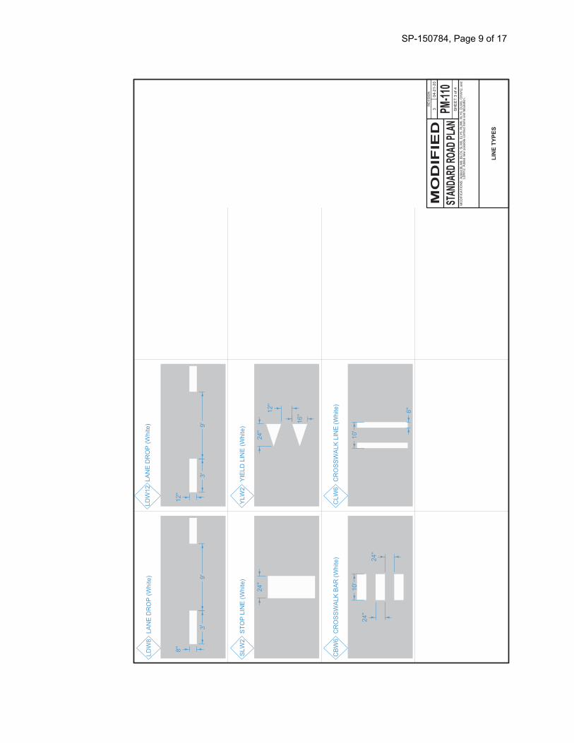
SP-150784, Page 9 of 17
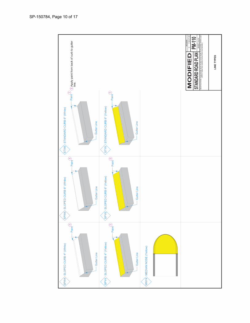
SP-150784, Page 10 of 17
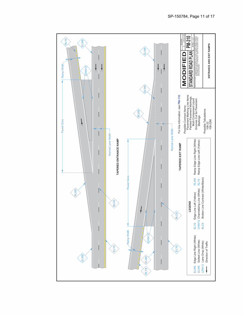
SP-150784, Page 11 of 17
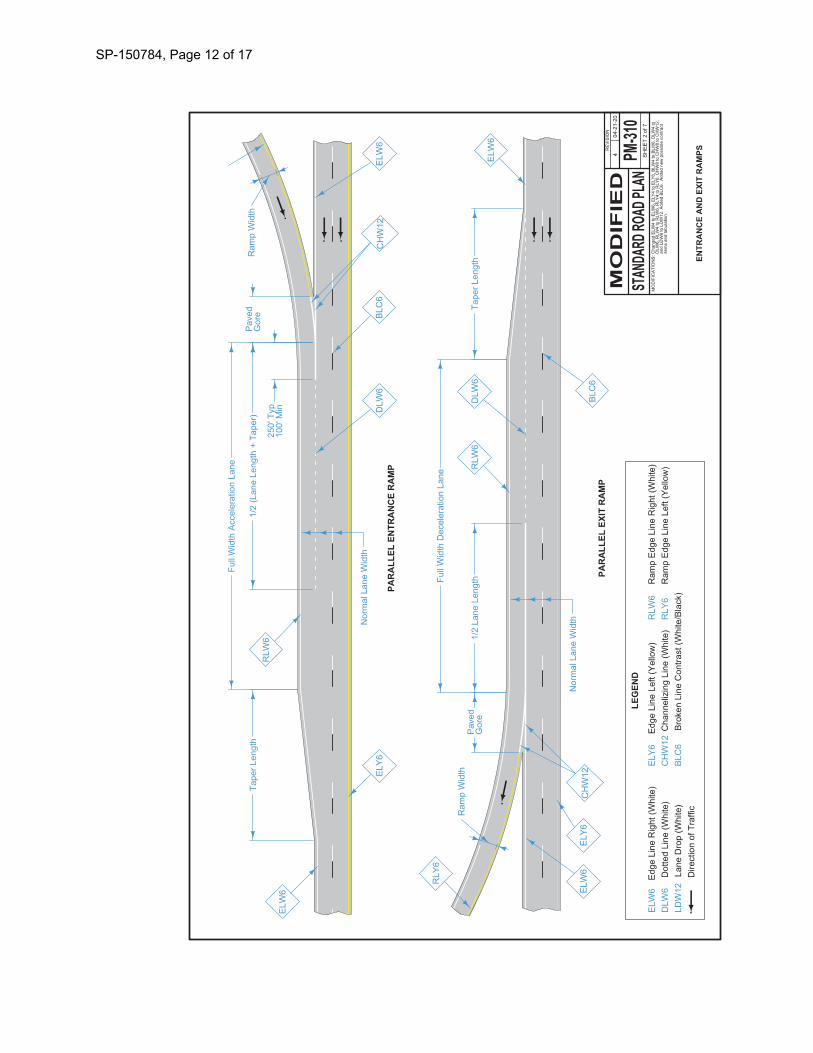
SP-150784, Page 12 of 17
SP-150784, Page 13 of 17
SP-150784, Page 14 of 17
SP-150784, Page 15 of 17
SP-150784, Page 16 of 17
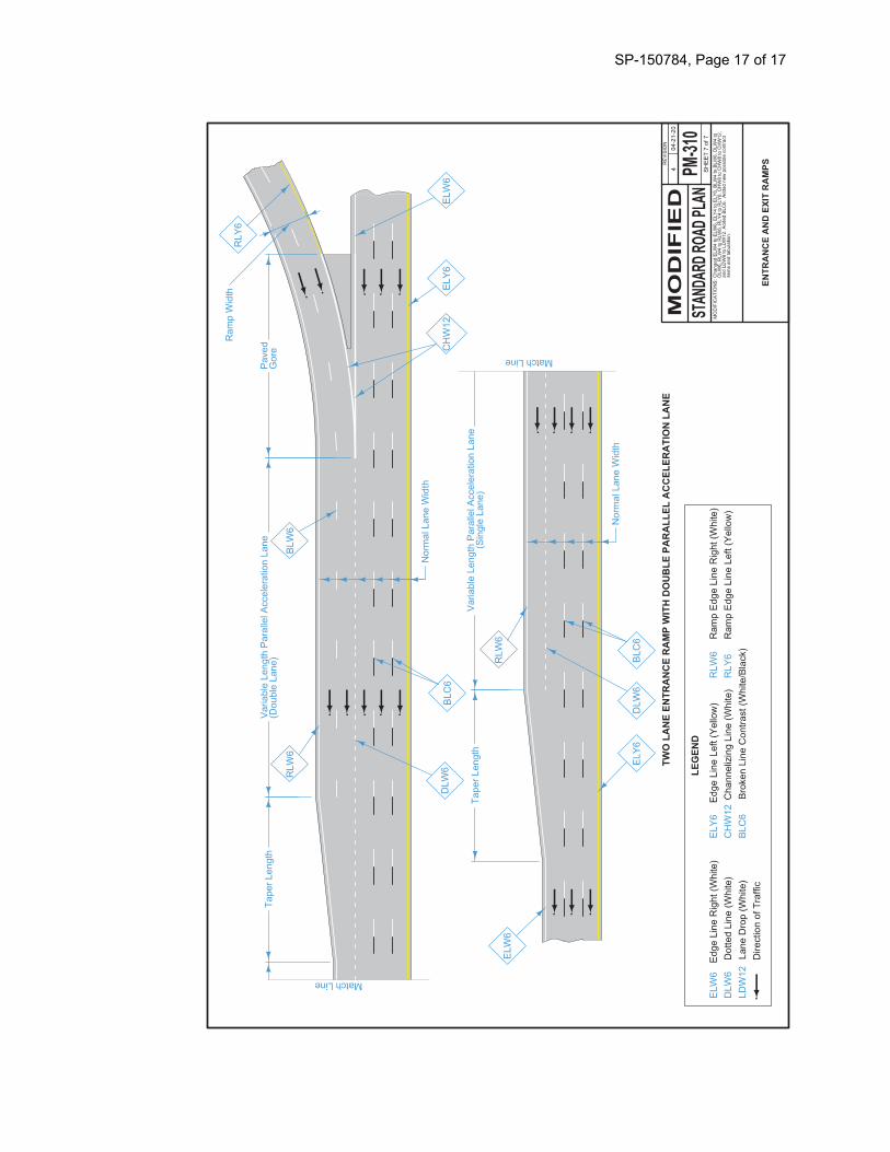
SP-150784, Page 17 of 17