Embed Size (px)
Citation preview
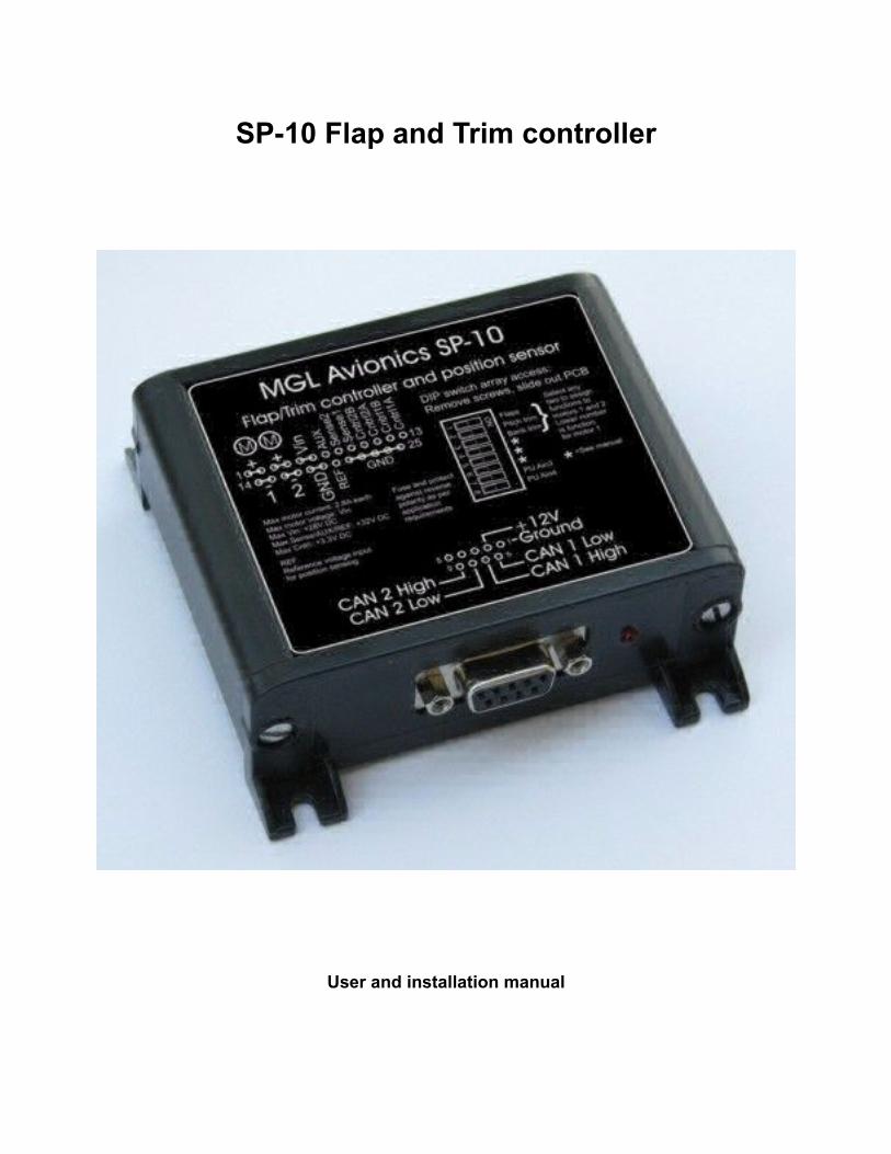
SP-10 Flap and Trim controller
User and installation manual
Table of ContentsGeneral........................................................................................................................................3Hardware interfaces....................................................................................................................3REF input....................................................................................................................................3Flaps controller............................................................................................................................5Pitch and Roll controllers............................................................................................................5Programming the flap positions..................................................................................................5
Programming using 4 push buttons........................................................................................5If the position programming is not working:........................................................................7
Programming using iEFIS.......................................................................................................7Reading...................................................................................................................................8Flaps up, Flaps 1, Flaps 2 and Flaps down position .............................................................8Move flaps up, move flaps down............................................................................................8Flaps motor current.................................................................................................................8Flaps motor timeout................................................................................................................9
Using the flaps controller with the iEFIS.....................................................................................9Alternate flap control:............................................................................................................10Using panel buttons .............................................................................................................11
Pitch trim controller....................................................................................................................11Using the Pitch trim controller with the iEFIS............................................................................12
Alternate Pitch trim control....................................................................................................12Roll trim controller.....................................................................................................................14Using the Roll trim controller with the iEFIS.............................................................................15
Alternate Roll trim control.....................................................................................................15Installation of the SP-10............................................................................................................17
Switches 1,2 and 3................................................................................................................19Switches 4, 5 and 6...............................................................................................................20Switches 7 and 8...................................................................................................................20
CAN bus....................................................................................................................................20Motor control.............................................................................................................................20
Motor off condition................................................................................................................21Motor direction......................................................................................................................21
Diagnostics................................................................................................................................22Flap control options...................................................................................................................23
4 button flap control..............................................................................................................236 button flap control..............................................................................................................232 button flap control..............................................................................................................23Mixing controls......................................................................................................................23
Conflicts.....................................................................................................................................23Wiring diagrams........................................................................................................................24Resistor color codes..................................................................................................................28Technical specifications.............................................................................................................29Fusing........................................................................................................................................29Supply.......................................................................................................................................29Motor EMF.................................................................................................................................29
GeneralThe SP-10 Flap and Trim controller is used with MGL iEFIS systems. It can also be used as a stand-alone 4 position flap controller.The SP-10 provides two independent H-bridge motor controls, each capable of delivering 2.8A of DC current. If the SP-10 is used in single motor mode, the SP-10 can deliver 5A of current to the motor.The SP-10 is used primarily as a 4 position flap controller, a pitch trim controller and a roll trim controller. Either two functions or a single function may be selected by means of an internal DIP switch array.The SP-10 provides two position monitoring functions. These are used as flap or trim motor position monitoring for display on an EFIS or compatible system. For the flap controller function the position feedback is used to position the flaps in one of four positions (Flaps up, flaps mid 1, flaps mid 2 and flaps down).t is possible to connect the SP-10 to two independent external control sources such as an EFIS and a panel mount controller for example. Two independent CAN bus interfaces are used for this.Up to 4 SP-10 units may be connected to a host system via CAN bus but in practice a maximum of three will be used as three functions can be defined.
Hardware interfacesOne or two DC motor drivers (H bridge, fault and thermal protected, PWM motor torque control).Two motor position feedback inputs. DC inputs plus external voltage reference for accurate, supply voltage independent positioning.4 analog inputs for attaching of optional switches (momentary push buttons).2 CAN bus interfaces for connection to two independent control sources (EFIS etc).
REF inputThe SP-10 features a reference input used as voltage reference for measurement of voltage levels on the Sense1, Sense2 and AUX inputs. This allows relative (ratiometric) measurement of the voltage level on these inputs, automatically compensating for supply voltage variations. Typical uses of this is when you are using a potentiometer as position sense input connected between ground and the aircraft power supply – the output voltage will vary not only with position but with the supply voltage level as well. Relative measurement cancels this effect out resulting in stable and repeatable position readings.Relative mode is selected with DIP switch 6 is OFF and a voltage higher than about 2V is measured on the REF input.Absolute mode is selected with DIP switch 6 ON or if the voltage on the REF input is lower than about 2V (or the REF input is not connected). In absolute mode the voltage on the Sense1, Sense2 and AUX inputs is reflected against a stable and accurate internal reference voltage. You would select this mode of operation if your position sensing signal is not affected

by supply voltage variations. This may be the case for example if you are using an electronic sensor.If you are not sure which of the two methods to use, connect a volt meter to your sense line and measure the voltage at a given flap or trim position. Do this while the aircraft is running on internal battery power preferably with a reasonably discharged battery. If you are running a 12V system, a good voltage would be around 12V.Now attach a battery charger and allow the battery to charge for a while. The battery voltage should rise quickly to above 13V. Now measure the voltage at your sense line again. If the voltage has remained the same then you should use absolute mode (DIP switch 6 ON, no REF voltage connection needed).If your sense line voltage increased by about the same ratio as the supply voltage then you need to use relative (ratiometric) mode. Select DIP switch 6 to OFF and connect the REF line to your 12V supply.In the unlikely event that your sense line voltage reduced with increasing supply voltage: Recheck your measurements – something is not right. Did your flaps/trim move ?
Flaps controllerThe flaps controller accepts an input from the iEFIS (typically a touch screen flap position command) and positions the flaps accordingly. Position feedback is sent to the iEFIS for flap position display on the screen.Alternatively, it is also possible to command one of the four flap positions by means of panel mount switches (momentary contact switches).If used in stand-alone mode, it is possible to teach the SP-10 the four flap positions by means of the switches only so no EFIS is needed. In this mode motor current limit is automatically selected to be at maximum capability.It is possible to use the flaps controller with no switches (control via EFIS only), with 4 switches or with 6 switches. In the latter case two switches are used to position flaps to any position (motor moves as long as switch activated).
Pitch and Roll controllersThe pitch and roll controllers are very similar. The controlling system pulses the motor in the desired direction for a given time. It is also possible for the controlling system to seek to a given position but this is not normally used as pitch and roll trimming tends to be dynamic.Position end points are programmed via the controlling system so maximum positions can be set without resorting to mechanical limit switches or similar.Position is fed back to the controlling system for display.Pitch and/or Roll control can be used by an autopilot for automatic trim adjustment in flight if trim sensing servos such as the MGL autopilot servos are used. If required, this is configured as part of the autopilot setup.
Programming the flap positionsProgramming flap positions is done either via iEFIS flap controller setup menu or using 4 momentary push buttons.
Programming using 4 push buttons.Note: This method is usually only performed if you are using the SP-10 as stand-alone flap controller. Use the EFIS if available to perform this task.The buttons are labeled Flaps up (button 1)Flaps 1 (button 2)Flaps 2 (button 3)Flaps down (button 4)To start flaps position programming, hold down both button 1 and button 4 for 6 seconds, then

release the buttons at the same time.The system is now in setup mode. In this mode the buttons are used as:Move motor direction 1 (button 1)Set position ID (button 2)Leave setup mode (button 3)Move motor direction 2 (button 4)Use button 1 or button 4 to position the flaps to the desired position you want to assign. Do not be concerned with the direction the flaps may move when you do this – the buttons have now no knowledge of flaps up or down – they simply move the motor one direction or the other.Once you have the desired position you need to program it. You do this by using button 2. Press button 2 once for “Flaps up”, twice for “Flaps 1”, three times for “Flaps 2” and four times for “Flaps down”.You can set the positions in any order and you do not have to set all four of them unless you do this the first time in which case you must set all four positions.Once you have pressed button 2 the desired number of times, do not press any more buttons for 6 seconds. If you press button 1,3 or 4 before the 6 seconds are over you will cancel the programming.After 6 seconds have elapsed the current position has been stored and you can move on to the next position.Example sequence to store all 4 positions:
1) Press buttons 1 and 4 for 6 seconds, then release.2) Use buttons 1 and 4 to position “flaps up”3) Press button 2 for 1 second and then release. Now wait 6 seconds or more.4) Use buttons 1 and 4 to position “Flaps 1”5) Press button 2 for 1 second and then release for 1 second, press again for 1 second and release. Now wait 6 seconds or more.6) Use buttons 1 and 4 to position “Flaps 2”7) Press button 2 for 1 second and release 1 second three times. Then wait 6 seconds or more.8) Use buttons 1 and 4 to position “Flaps down”9) Press button 2 for 1 second and release 1 second four times. Then wait 6 seconds or more.Finally either power the SP10 down and then up again or press button 3 to end the programming process. Now test your setup by using buttons 1 to 4.Note: If your setup has 6 buttons, only the 4 flap position buttons are used during programming as described here. The two additional buttons normally used for direct flap motor control are not functional during programming.
If the position programming is not working:If you are able to move the motor in both directions once in program mode but programming fails the most likely reason is that the position feedback is not working. Please connect a volt meter to pin 9 of the D25 connector (Sense 1). The voltage should change significantly and repeatedly as you move the flap position.For example, with a 12V system, you may find positions at 3V, 5V, 7V and 9V. It does not matter if the voltage increases or decreases with flap position but it must be consistent and you need to get the same voltage reading at the same position.Also check pin 7 (REF). This is the reference voltage. This voltage should be the same as is connected to your positioning sensor (often either 12V or 24V). The SP10 measures this voltage to be able to cancel out effects of supply voltage variations. This pin must be connected.
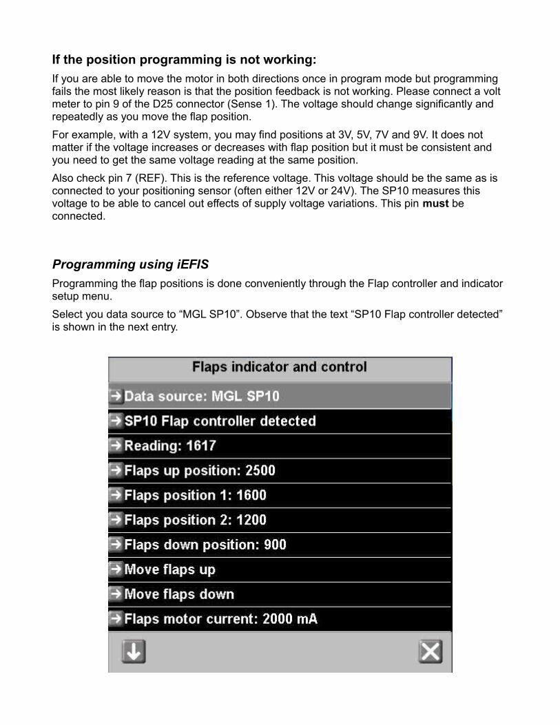
Programming using iEFISProgramming the flap positions is done conveniently through the Flap controller and indicator setup menu.Select you data source to “MGL SP10”. Observe that the text “SP10 Flap controller detected” is shown in the next entry.
ReadingThis is the current reading from the “Sense 1” input on the SP10. This number can range from 0 to 4095. “4095” means the voltage at “Sense 1” is the same as on the “REF” input of the SP10 (usually 12V or 24V aircraft power supply).
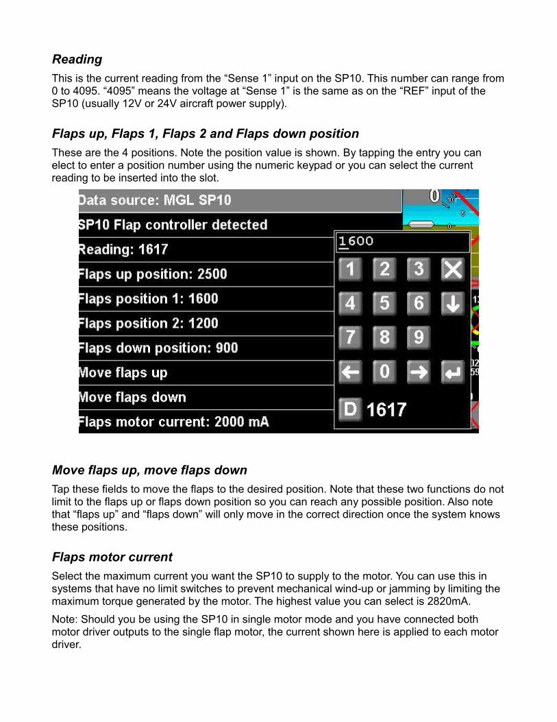
Flaps up, Flaps 1, Flaps 2 and Flaps down position These are the 4 positions. Note the position value is shown. By tapping the entry you can elect to enter a position number using the numeric keypad or you can select the current reading to be inserted into the slot.
Move flaps up, move flaps downTap these fields to move the flaps to the desired position. Note that these two functions do not limit to the flaps up or flaps down position so you can reach any possible position. Also note that “flaps up” and “flaps down” will only move in the correct direction once the system knows these positions.
Flaps motor currentSelect the maximum current you want the SP10 to supply to the motor. You can use this in systems that have no limit switches to prevent mechanical wind-up or jamming by limiting the maximum torque generated by the motor. The highest value you can select is 2820mA.Note: Should you be using the SP10 in single motor mode and you have connected both motor driver outputs to the single flap motor, the current shown here is applied to each motor driver.
Flaps motor timeoutHere you enter in seconds, how long should the motor remain on if the target position cannot be reached for some reason. Select a value that is greater than the maximum time it takes to move from flaps up to flaps down and flaps down to flaps up.The motor will be switched off if this time has been exceeded without the target position having reached.
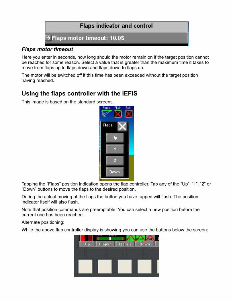
Using the flaps controller with the iEFISThis image is based on the standard screens.
Tapping the “Flaps” position indication opens the flap controller. Tap any of the “Up”, “1”, “2” or “Down” buttons to move the flaps to the desired position.During the actual moving of the flaps the button you have tapped will flash. The position indicator itself will also flash.Note that position commands are preemptable. You can select a new position before the current one has been reached.Alternate positioning:While the above flap controller display is showing you can use the buttons below the screen:
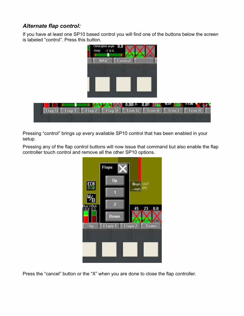
Alternate flap control:If you have at least one SP10 based control you will find one of the buttons below the screen is labeled “control”. Press this button.
Pressing “control” brings up every available SP10 control that has been enabled in your setup.Pressing any of the flap control buttons will now issue that command but also enable the flap controller touch control and remove all the other SP10 options.
Press the “cancel” button or the “X” when you are done to close the flap controller.
Using panel buttons If your SP10 flap controller has also been fitted with panel mount buttons (either 4 or 6) these remain active at all times. The EFIS flap indicator will show the flap position even if you commanded the position from one of the buttons.
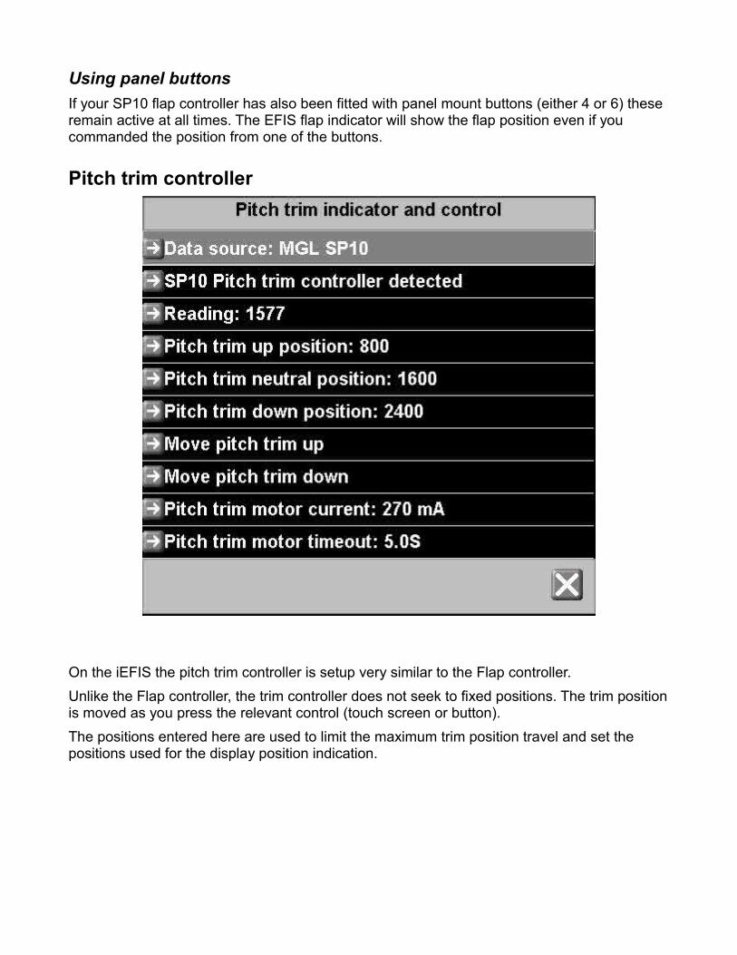
Pitch trim controller
On the iEFIS the pitch trim controller is setup very similar to the Flap controller.Unlike the Flap controller, the trim controller does not seek to fixed positions. The trim position is moved as you press the relevant control (touch screen or button).The positions entered here are used to limit the maximum trim position travel and set the positions used for the display position indication.
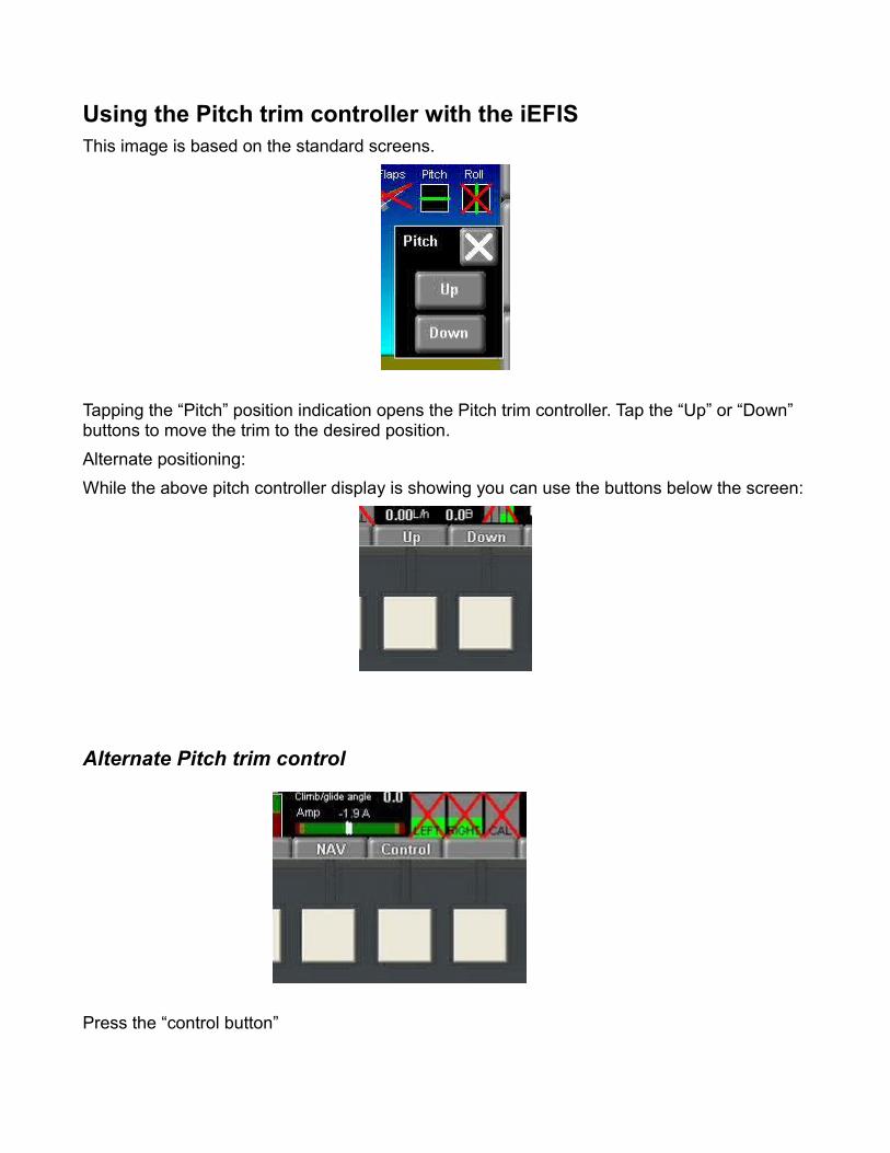
Using the Pitch trim controller with the iEFISThis image is based on the standard screens.
Tapping the “Pitch” position indication opens the Pitch trim controller. Tap the “Up” or “Down” buttons to move the trim to the desired position.Alternate positioning:While the above pitch controller display is showing you can use the buttons below the screen:
Alternate Pitch trim control
Press the “control button”
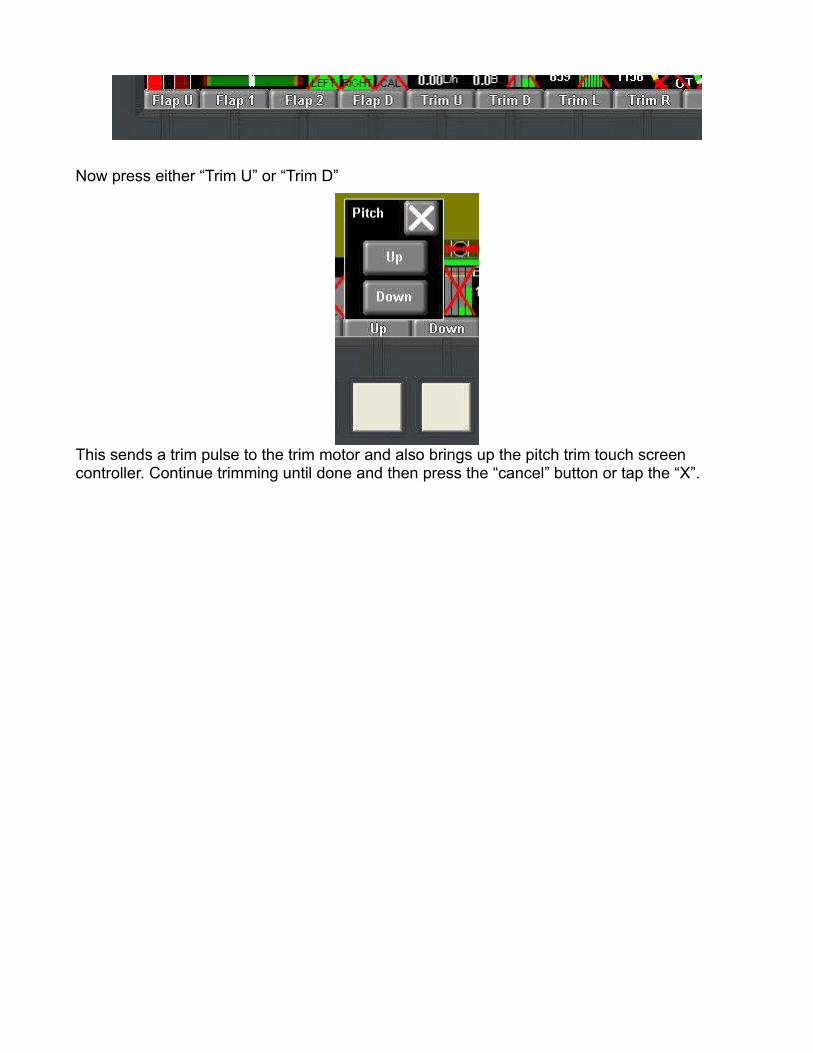
Now press either “Trim U” or “Trim D”
This sends a trim pulse to the trim motor and also brings up the pitch trim touch screen controller. Continue trimming until done and then press the “cancel” button or tap the “X”.
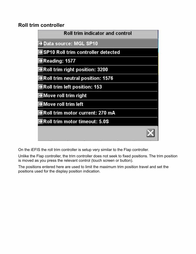
Roll trim controller
On the iEFIS the roll trim controller is setup very similar to the Flap controller.Unlike the Flap controller, the trim controller does not seek to fixed positions. The trim position is moved as you press the relevant control (touch screen or button).The positions entered here are used to limit the maximum trim position travel and set the positions used for the display position indication.
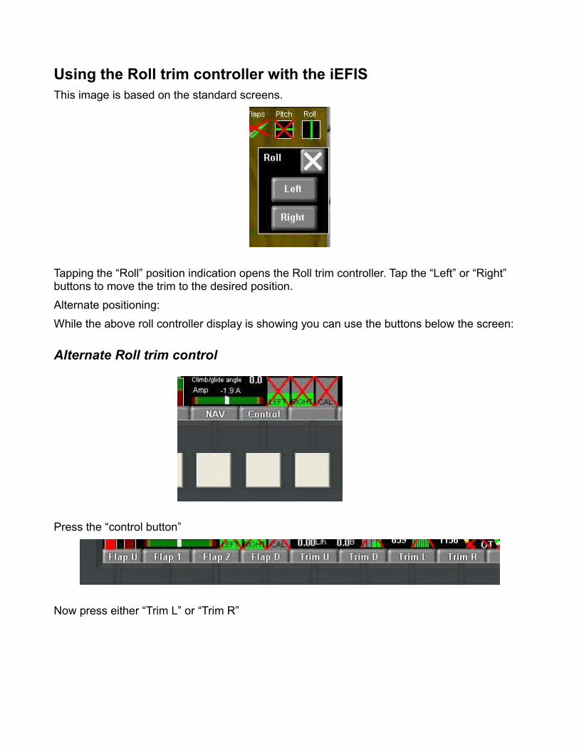
Using the Roll trim controller with the iEFISThis image is based on the standard screens.
Tapping the “Roll” position indication opens the Roll trim controller. Tap the “Left” or “Right” buttons to move the trim to the desired position.Alternate positioning:While the above roll controller display is showing you can use the buttons below the screen:
Alternate Roll trim control
Press the “control button”
Now press either “Trim L” or “Trim R”
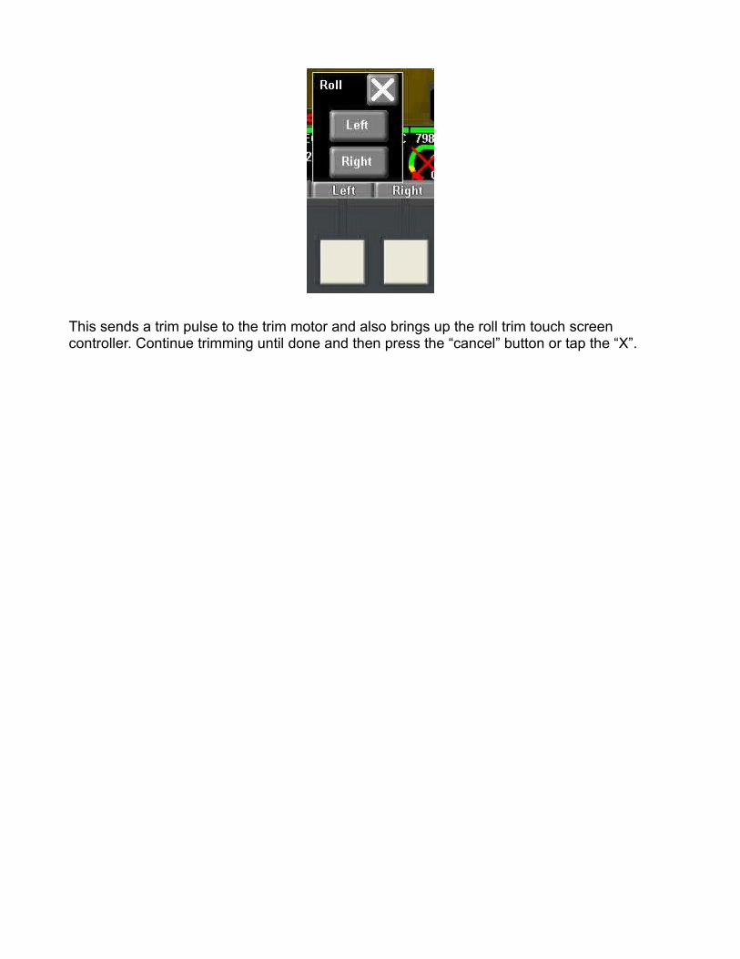
This sends a trim pulse to the trim motor and also brings up the roll trim touch screen controller. Continue trimming until done and then press the “cancel” button or tap the “X”.
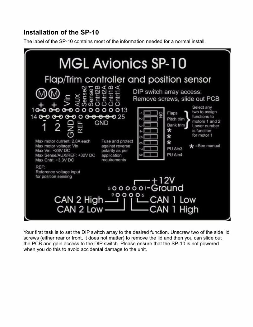
Installation of the SP-10The label of the SP-10 contains most of the information needed for a normal install.
Your first task is to set the DIP switch array to the desired function. Unscrew two of the side lid screws (either rear or front, it does not matter) to remove the lid and then you can slide out the PCB and gain access to the DIP switch. Please ensure that the SP-10 is not powered when you do this to avoid accidental damage to the unit.
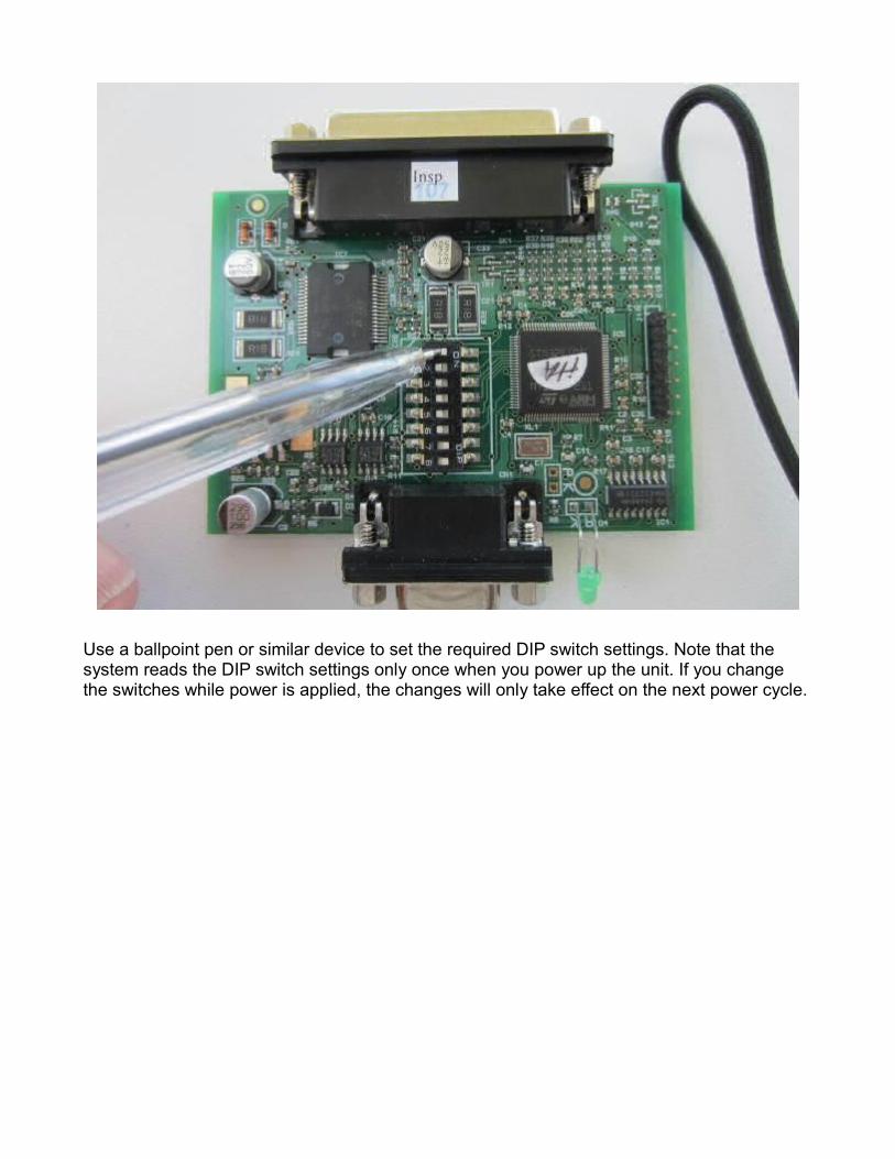
Use a ballpoint pen or similar device to set the required DIP switch settings. Note that the system reads the DIP switch settings only once when you power up the unit. If you change the switches while power is applied, the changes will only take effect on the next power cycle.
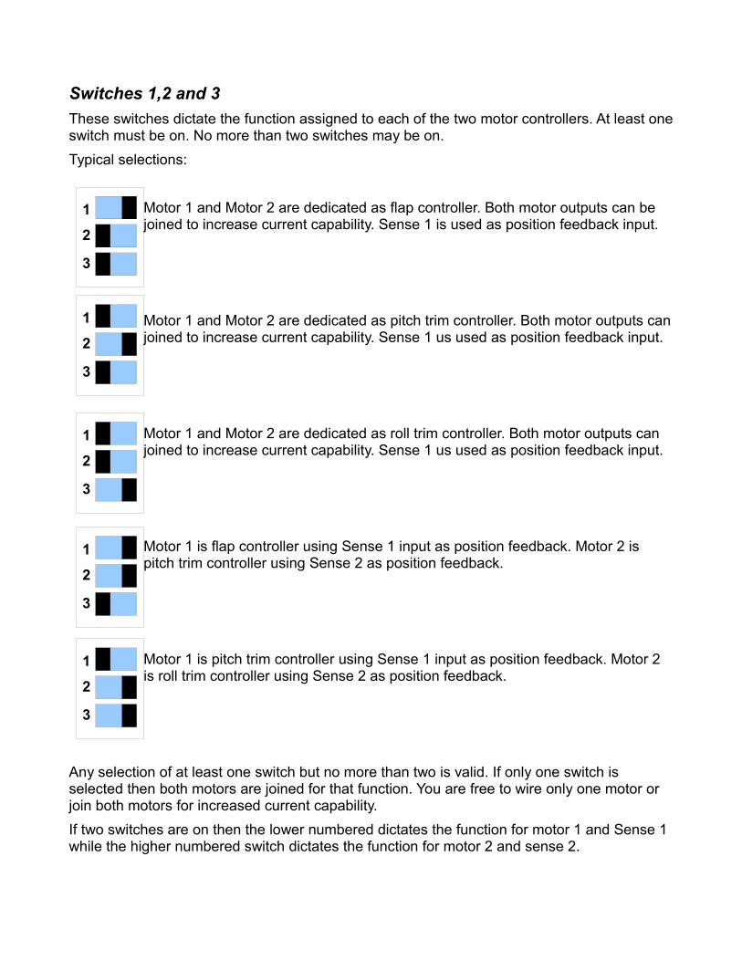
Switches 1,2 and 3These switches dictate the function assigned to each of the two motor controllers. At least one switch must be on. No more than two switches may be on.Typical selections:
Motor 1 and Motor 2 are dedicated as flap controller. Both motor outputs can be joined to increase current capability. Sense 1 is used as position feedback input.
Motor 1 and Motor 2 are dedicated as pitch trim controller. Both motor outputs can joined to increase current capability. Sense 1 us used as position feedback input.
Motor 1 and Motor 2 are dedicated as roll trim controller. Both motor outputs can joined to increase current capability. Sense 1 us used as position feedback input.
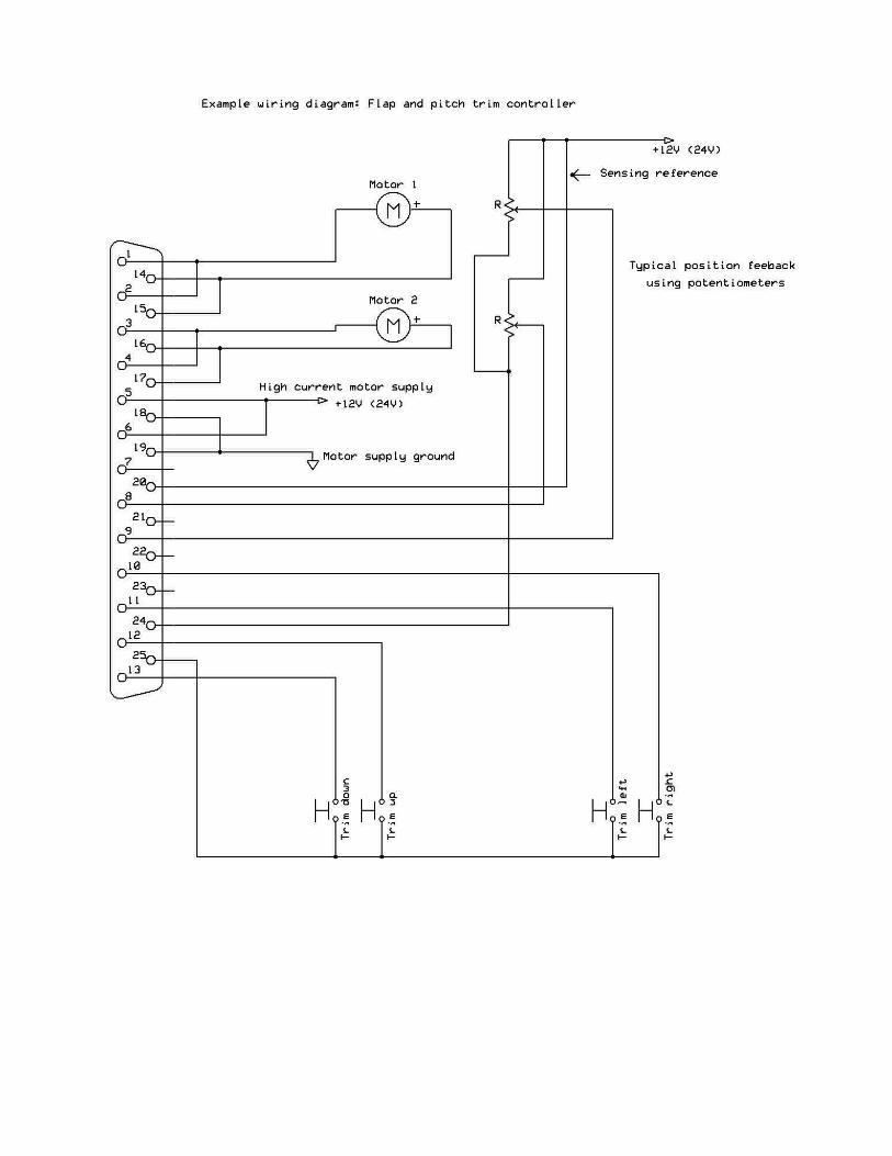
Motor 1 is flap controller using Sense 1 input as position feedback. Motor 2 is pitch trim controller using Sense 2 as position feedback.
Motor 1 is pitch trim controller using Sense 1 input as position feedback. Motor 2 is roll trim controller using Sense 2 as position feedback.
Any selection of at least one switch but no more than two is valid. If only one switch is selected then both motors are joined for that function. You are free to wire only one motor or join both motors for increased current capability.If two switches are on then the lower numbered dictates the function for motor 1 and Sense 1 while the higher numbered switch dictates the function for motor 2 and sense 2.
1
2
3
1
2
3
1
2
3
1
2
3
1
2
3
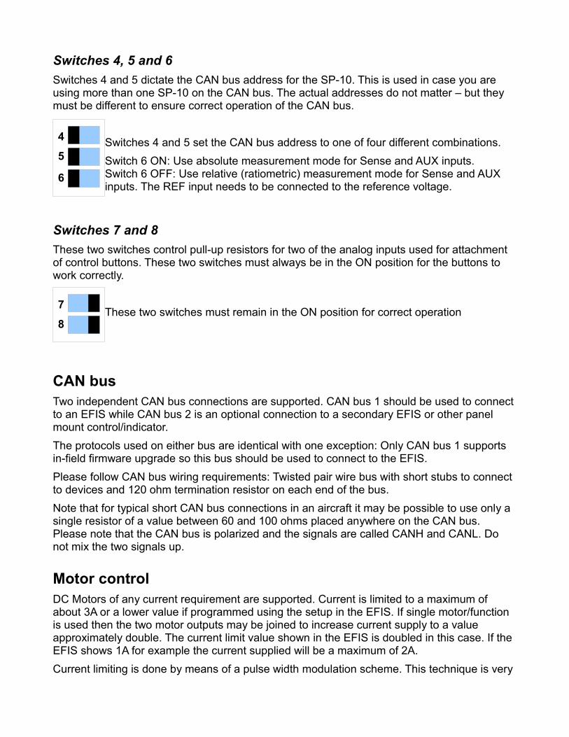
Switches 4, 5 and 6Switches 4 and 5 dictate the CAN bus address for the SP-10. This is used in case you are using more than one SP-10 on the CAN bus. The actual addresses do not matter – but they must be different to ensure correct operation of the CAN bus.
Switches 4 and 5 set the CAN bus address to one of four different combinations. Switch 6 ON: Use absolute measurement mode for Sense and AUX inputs.Switch 6 OFF: Use relative (ratiometric) measurement mode for Sense and AUX inputs. The REF input needs to be connected to the reference voltage.
Switches 7 and 8These two switches control pull-up resistors for two of the analog inputs used for attachment of control buttons. These two switches must always be in the ON position for the buttons to work correctly.
These two switches must remain in the ON position for correct operation
CAN busTwo independent CAN bus connections are supported. CAN bus 1 should be used to connect to an EFIS while CAN bus 2 is an optional connection to a secondary EFIS or other panel mount control/indicator.The protocols used on either bus are identical with one exception: Only CAN bus 1 supports in-field firmware upgrade so this bus should be used to connect to the EFIS.Please follow CAN bus wiring requirements: Twisted pair wire bus with short stubs to connect to devices and 120 ohm termination resistor on each end of the bus. Note that for typical short CAN bus connections in an aircraft it may be possible to use only a single resistor of a value between 60 and 100 ohms placed anywhere on the CAN bus. Please note that the CAN bus is polarized and the signals are called CANH and CANL. Do not mix the two signals up.
Motor controlDC Motors of any current requirement are supported. Current is limited to a maximum of about 3A or a lower value if programmed using the setup in the EFIS. If single motor/function is used then the two motor outputs may be joined to increase current supply to a value approximately double. The current limit value shown in the EFIS is doubled in this case. If the EFIS shows 1A for example the current supplied will be a maximum of 2A.Current limiting is done by means of a pulse width modulation scheme. This technique is very
4
5
6
7
8
power efficient and leads to a minimum of heat generated.The SP10 includes thermal monitoring of the motor driver circuit. Should temperatures rise too high the motor control will be shut off until temperatures fall to acceptable levels. The temperature limit is set to a die temperature of 160 degrees Celsius.
Motor off conditionWhen a motor is switched off, the two motor supply terminals are shorted to ground resulting in a motor braking effect. This reduces run-on of the motor after power is removed.
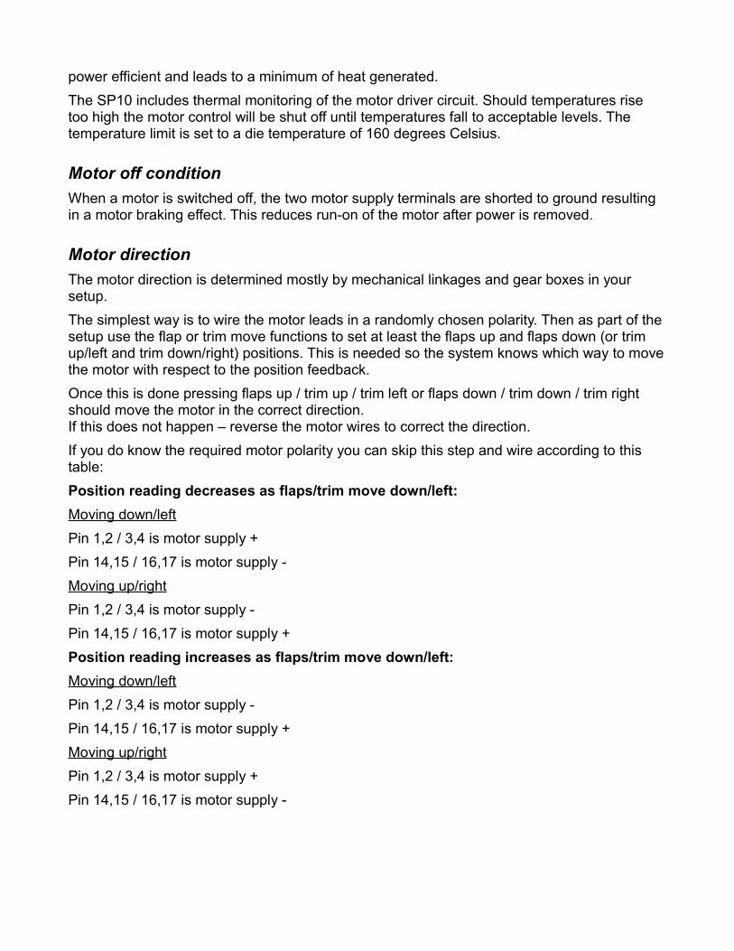
Motor directionThe motor direction is determined mostly by mechanical linkages and gear boxes in your setup.The simplest way is to wire the motor leads in a randomly chosen polarity. Then as part of the setup use the flap or trim move functions to set at least the flaps up and flaps down (or trim up/left and trim down/right) positions. This is needed so the system knows which way to move the motor with respect to the position feedback.Once this is done pressing flaps up / trim up / trim left or flaps down / trim down / trim right should move the motor in the correct direction. If this does not happen – reverse the motor wires to correct the direction.If you do know the required motor polarity you can skip this step and wire according to this table:Position reading decreases as flaps/trim move down/left:Moving down/leftPin 1,2 / 3,4 is motor supply +Pin 14,15 / 16,17 is motor supply -Moving up/rightPin 1,2 / 3,4 is motor supply -Pin 14,15 / 16,17 is motor supply +Position reading increases as flaps/trim move down/left:Moving down/leftPin 1,2 / 3,4 is motor supply -Pin 14,15 / 16,17 is motor supply +Moving up/rightPin 1,2 / 3,4 is motor supply +Pin 14,15 / 16,17 is motor supply -
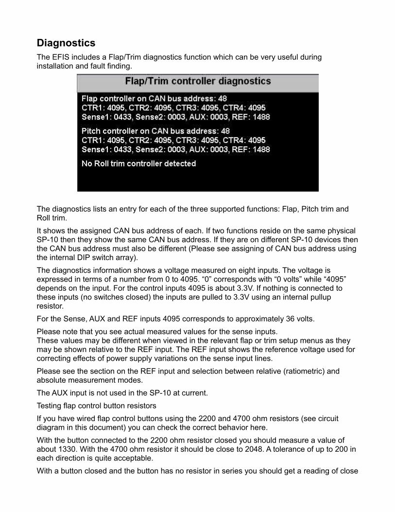
DiagnosticsThe EFIS includes a Flap/Trim diagnostics function which can be very useful during installation and fault finding.
The diagnostics lists an entry for each of the three supported functions: Flap, Pitch trim and Roll trim.It shows the assigned CAN bus address of each. If two functions reside on the same physical SP-10 then they show the same CAN bus address. If they are on different SP-10 devices then the CAN bus address must also be different (Please see assigning of CAN bus address using the internal DIP switch array).The diagnostics information shows a voltage measured on eight inputs. The voltage is expressed in terms of a number from 0 to 4095. “0” corresponds with “0 volts” while “4095” depends on the input. For the control inputs 4095 is about 3.3V. If nothing is connected to these inputs (no switches closed) the inputs are pulled to 3.3V using an internal pullup resistor. For the Sense, AUX and REF inputs 4095 corresponds to approximately 36 volts.Please note that you see actual measured values for the sense inputs. These values may be different when viewed in the relevant flap or trim setup menus as they may be shown relative to the REF input. The REF input shows the reference voltage used for correcting effects of power supply variations on the sense input lines.Please see the section on the REF input and selection between relative (ratiometric) and absolute measurement modes.The AUX input is not used in the SP-10 at current.Testing flap control button resistorsIf you have wired flap control buttons using the 2200 and 4700 ohm resistors (see circuit diagram in this document) you can check the correct behavior here. With the button connected to the 2200 ohm resistor closed you should measure a value of about 1330. With the 4700 ohm resistor it should be close to 2048. A tolerance of up to 200 in each direction is quite acceptable.With a button closed and the button has no resistor in series you should get a reading of close
to 0. A value up to 100 is acceptable.
Flap control optionsFor local controls you can consider one of the following options:
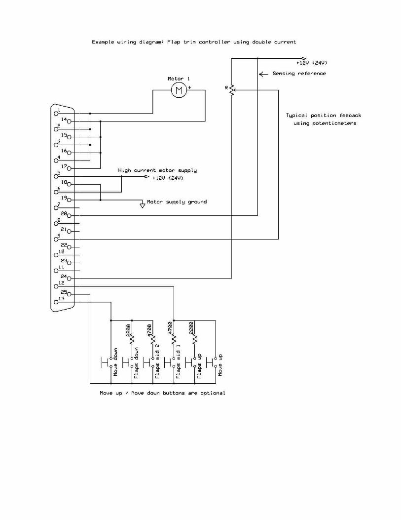
4 button flap controlHere you will use 4 push buttons (Normally open) wired as per sample wiring diagram. You use the buttons to select “Flap up”, “Flap position 1”, “Flap position 2” and “Flap down (Flap position 3”. To activate a selection a button must be pushed for at least 0.3 seconds to avoid accidental activations.Tip: if the 4 button control is the only local control used, you can consider a 4 position rotary or linear switch as well.
6 button flap controlThis uses the four buttons from the 4 button control and adds a further two buttons that allow continuous positioning. The motor runs as long as the button is pressed, subject to flap up and down position limits. Note that the additional two buttons are not subject to the 0.3 second delay.
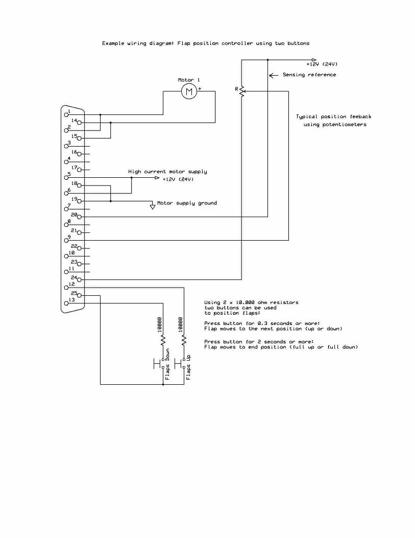
2 button flap controlThis uses only two buttons. Pressing either of the buttons for 0.3 seconds or longer will request the next flap position (either up or down depending on which button has been pressed). If the flaps happen to be between two positions the next position rule still applies.If a button is pressed for two seconds or longer, the flaps will move to the respective end points (either flaps fully up or fully down).
Mixing controlsIt is possible to mix the above controls. For example, you might install a 4 button flap control in your panel and have a two button control as part of stick mounted buttons.
ConflictsIf you have multiple controls installed it is possible to request conflicting flap positions. This will not cause any harm to the SP-10 or motors but of course the result of the request may be undefined. It is recommended that the installer verifies operation under various conflict conditions to ensure that flight safety will not be adversely affected.
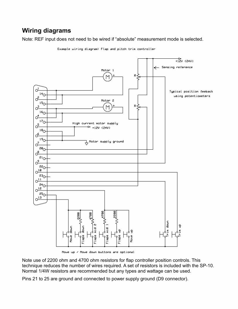
Wiring diagramsNote: REF input does not need to be wired if “absolute” measurement mode is selected.
Note use of 2200 ohm and 4700 ohm resistors for flap controller position controls. This technique reduces the number of wires required. A set of resistors is included with the SP-10. Normal 1/4W resistors are recommended but any types and wattage can be used. Pins 21 to 25 are ground and connected to power supply ground (D9 connector).

Resistor color codes
This image shows typical resistor color codes. Note: Some color codes for lower tolerance resistors may differ. If in doubt, use a ohm meter to verify resistance.
Technical specificationsMaximum motor supply voltage: +28V DCMotor supply ground = SP10 supply ground.Maximum motor supply current: 2.8A DC per motor output (limited to 3.0A maximum – motors with larger current demand may be connected but current will be limited to set maximum).Maximum voltage on sense 1, sense 2 , AUX and REF pins: 32V.Maximum voltage on Cntrl1, 2, 3 and 4 lines: 3.3V.Supply voltage range for SP-10: 8-16V DCSupply current for SP-10 (excluding motor current): 60mA at 13,8V DC.
FusingPlease supply the SP-10 via suitable fuses or circuit breakers that will prevent any electrical issues in the case of over current or short circuits.Recommended fusing for the SP-10 supply is 500mA slow blow.Fusing for the motor DC supply should be chosen according to maximum expected motor currents taking into account current limiting settings that may apply if the SP-10 is configured using an EFIS system.Total motor current should not exceed 6A (both circuits active).
SupplySupply for the SP-10 and motors are separate. Take note that the motor supply ground equals the SP-10 supply ground (they are connected).Motor DC supply should be drawn from a suitable source able to sustain the desired current. The motor DC supply voltage may be higher or lower than the SP-10 supply voltage.The SP-10 itself should be supplied by the avionics supply bus or alternate “clean” DC source.It is recommended that both the SP-10 and motor supply have a suitable arrangement for a backup supply in case main power fails. This will ensure that emergency control over flaps and trim will be maintained.
Motor EMFBrushed DC motors tend to create high voltage power spikes. These may superimpose themselves on DC supplies and can create interference or even damage avionics.The SP-10 employs suitable DC current paths that will shunt any current created by the motor(s) in a manner so as to not cause any undue issues. For this reason no further protection is needed.