Embed Size (px)
Citation preview
SOVIET AND EAST EUROPEAN DEVELOPMENTS IN
SURFACE EFFECT VEHICLES
Sponsored By
Defense Advanced Research Projects Agency
DARPA Order No. 3097
November 1975
DARPA Order No. 3097 Program Code No. P6L10, P6D10, P6E20, P6G10 Name of Contractor:
Informatics Inc. Effective Date of Contract:
September 1, 1975 Contract Expiration Date:
November 30, 1975 Amount of Contract: $100, 617
Contract No. MDA-903-76C-0099 Principal Investigator:
Stwart G. Hibben Tel: (301)770-3000
Program Manager; Ruth Ness Tel: (301)770-3i
Short Titld of Work: "Soviet SEV's"
ofi)
Li Lb
OLi
■
This research was supported by the Defense Advanced Research Projects Agency and was monitored by the Defense Supply Service - Washington, under Contract No. MDA-903-76C-0099. The views and conclusions contained in this document are those of the author and should not be interpreted as necessarily representing the official policies, either express or implied, of the Defense Advanced Research Projects Agency or the United States Government.
'•' Information Systems Company
Informatics Inc| ****™******** «ii
Rockvill«, Maryland 208S2 (301) 770-3000
Approved for public release; distribution unlimited
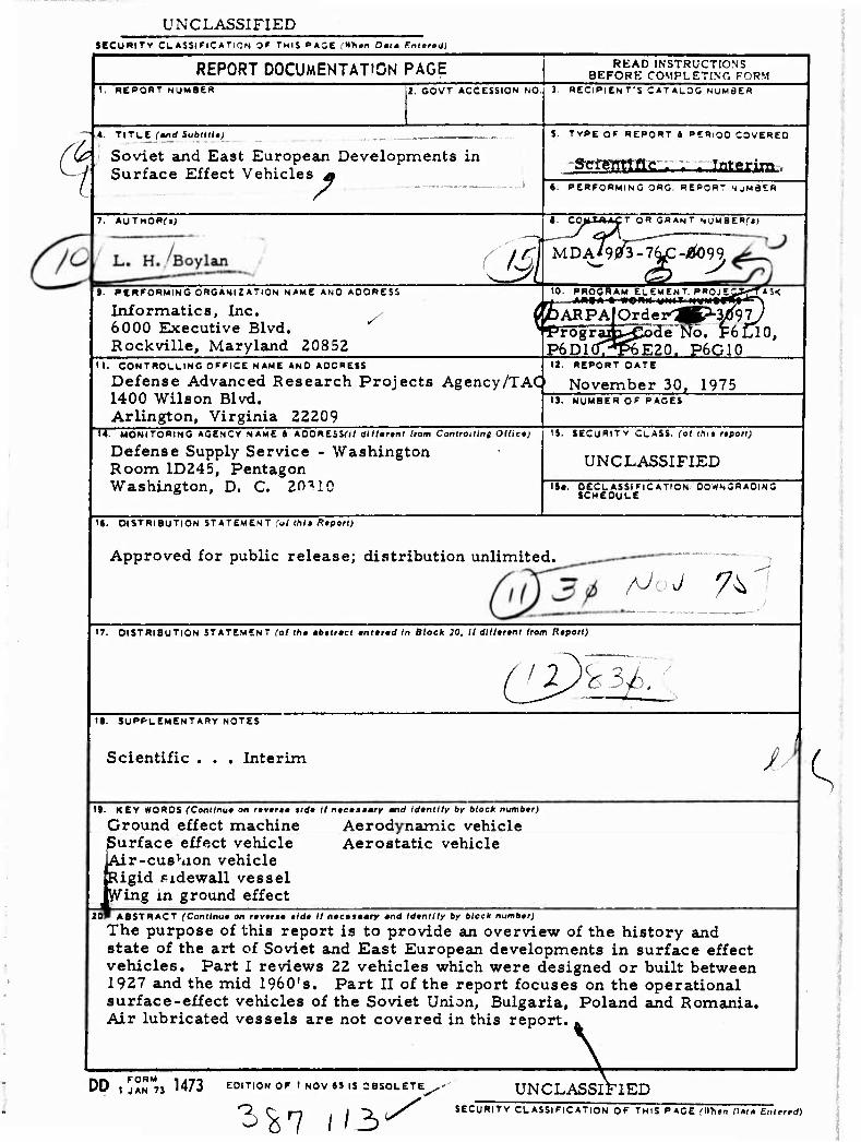
UNCLASSIFIED $ecu*iTv CLASSIFICATION OF THIS »AGE (Whin Oatm Emmrtäi
I
REPORT DOCUMENTATION PAGE t. REPORT NUMBEB 2. GOVT ACCESSION NO
4 TITLE (»nd Subdil«;
Soviet and East European Developments in Surface Effect Vehicles A
7. AUTMORrJj
// ^'!
9. PERFORMING ORGANIZATION NAME ANO AOORCSS
Informatics, Inc. 6000 Executive Blvd. Rockville, Maryland 20852
11. CONTROLLING OFFICE NAME AND ADDRESS
Defense Advanced Research Projects Agency/TAC1
1400 Wilson Blvd. Arlington, Virginia 22209
U. MONITORING AGENCY NAME 4 ADORESSm dllltrtnt from Controlling Oflictj
Defense Supply Service - Washington Room 1D245, Pentagon Washington, D. C. 20"» 10
READ INSTRUCTIONS BEFORE COMPLETING FORM
3. »EClPlEN T'S CAT ALOG NUMaE«
5. TYPE OF REPORT 1 PERIOD COVERED
•gsaagag « « Interim.. S. PERFORMING ORC. REPOR* NjMflER
I. COM.T«ACT OR GRANT S'jMSEB^j) 3^ M D A ' 9 sfä-Ki/Z-ÜO 99
A3< 10. PRO0RAM_ELEMENT. P»0J£_ . »j - A^SÄ ■ • wO"W WN41 • ■ Witf^w^^Ww • A
C PARPA\OTdej^gp'3/9jJ ^frogra^^^ode wo. F6Cl0,
P6D10T^P6E20. P6G10 12. REPORT DATE
November 30, 1975 13. NUMBER OF PAGES
IS. SECURITY CLASS, (ol thit fpori)
UNCLASSIFIED ISa. OECLASSIFiCATION DOWNGRADING
SCHEDULE
'«. DISTRIBUTION STATEMENT (ul Ihii RtpoH)
Approved for public release; distribution unlimited.
M. J 7^ '7. DISTRIBUTION STATEMENT (at Ifl« mbttrtct tnttrtd In Black 20, II dllltrtnl Iram Rtporl)
CJ^^Iä. /
H. SUPPLEMENTARY NOTES
Scientific . . . Interim / ^
19. KEY WORDS (Comfnu* on r«v»r<« lid« II ntcntmry and idenilly by block number;
Ground effect machine ßurface effect vehicle dr-cushion vehicle tigid fidewall vessel ring in ground effect
Aerodynamic vehicle Aerostatic vehicle
20P ABSTRACT (Conilnu» on r*v*r<* tidt II n«cej«ary «nd Idtnllly by block number;
The purpose of this report is to provide an overview of the history and state of the art of Soviet and East European developments in surface effect vehicles. Part I reviews 22 vehicles which were designed or built between 1927 and the mid 1960^. Part II of the report focuses on the operational surface-effect vehicles of the Soviet Union, Bulgaria, Poland and Romania. Air lubricated vessels are not covered in this report.
DD FORM
I JAN 73 1473 EDITION OF I NOV «5 IS OBSOLETE
3^7 (/3/' VSSIF] UNCLASSIFIED
SECURITY CLASSIFICATION OF TMIS PAGE C'lTien nnm Enterrd)
I I I 0 i:
[;
;
i.
..
INTRODUCTION
The purpose of this report is to provide an overview of the history and state of the art of Soviet and East European developments in surface effect vehicles. Part I reviews 22 vehicles which were designed or built between 1927 and the mid 1960*8. Part II of the report focuses on the operational surface-effect vehicles of the Soviet Union, Bulgaria, Poland, and Romania. Air lubricated vessels are not covered in this report, and those interested in descriptions of air-lubricated vessels are referred to Jane's Surface Skimmers; Hovercraft and Hydrofoils [146]. Another excellent source of information on Soviet ACV development is an article by J. S. Dibbern, published in the Canadian Aeronautics and Space Journal [145]. The present report, hopefully, supplements the information carried in the two fine sources cited above.
It should be noted that, following the discussion of each vehicle, a numerical listing of references to that vehicle has been included. Not all of the citations in the reference list have been used in the report, however, it is felt that all the citations contain meaningful information on the report topic.
ii
[
I
:
H
TABLE OF CONTENTS
Introduction • ii
PART I. HISTORY 1
PART II. OPERATIONAL SURFACE EFFECT VEHICLES 25
A. SOVIET UNION 25
1. Air-Cushion Vehicles 25
Sormovich 25 Navy ACV-1967 28 Navy ACV-1969 ("Gus") 31 Navy ACV-1975 32 Briz 32 Khar'kov Aviation Institute ACV 34 Skat 35 X-3 Hovercycle 36 Tayfun 37
2. Rigid Sidewall ACV s .' 39
Gor'kovchanin (Zarnitsa)) 39 Orion 41
3. Aerodynamic Surface Effect Vehicles 42
OIIMF-Series Aerodynamic SEV's 43 ESKA-1 45 Shmel' 48 Large Surface Effect Ships 48
4. Air Cushion Landing Systern. 52
5. Hybrid Vehicles, Hovertrailers, and Platforms 54
Six-Ton Tracked Hovercrawler 55 PVP-40 Hovertrailer 55 170-Ton Air-Cushion Drill Rig 56
B. POLAND 57
UrsynowM-6 Agricultural ACV ,. 57
in
C. ROMANIA 60
023E Experimental ACV 60 R-7 Experimental ACV 60
D. BULGARIA 61
Ikar-2 Amateur ACV 61
Comments 62
References 63
\
.
iv
PART I. HISTORY
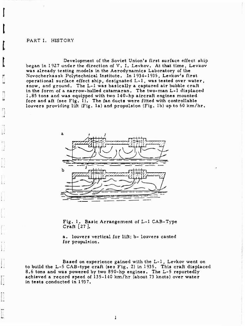
Development of the Soviet Union's first surface effect ship began in 1 9Z7 under the direction of V. I. Levkov. At that time, Levkov was already testing models in the Aerodynamics Laboratory of the Novocherkassk Polytechnical Institute. In 1934-1935, Levkov's first operational surface effect ship, designated L-l, was tested over water, snow, and ground. The L-l was basically a captured air bubble craft in the form of a narrow-hulled catamaran. The two-man L-l displaced 1.85 tons and was equipped with two 140-hp aircraft engines mounted fore and aft (see Fig. 1). The fan ducts were fitted with controllable louvers providing lift (Fig. la) and propulsion (Fig. lb) up to 60 km/hr.
S^x^H '^S,
SI%_Ä-
Fig. 1. Basic Arrangement of L-l CAB-Type Craft [27].
a. louvers vertical for lift; b- louvers canted for propulsion.
Based on experience gained with the L-l, Levkov went on to build the L-5 CAB-type craft (see Fig. 2) in 1935. This craft displaced 8.6 tons and was powered by two 890-hp engines. The L-5 reportedly achieved a record speed of 135-140 km/hr (about 73 knots) over water in tests conducted in 1937.
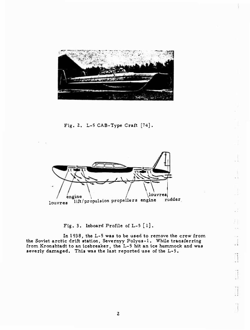
Fig. 2. L-5 CAB-Type Craft [74].
.tm—i
\
engine \ \louvres
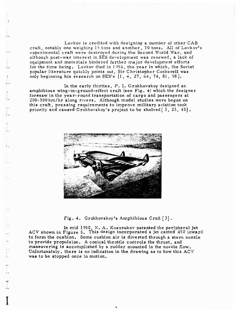
louvres lift/propulsion propellers engine rudder,
Fig. 3. Inboard Profile of L-5 [l].
In 1938, the L-5 was to be used to remove the crew from the Soviet arctic drift station, Severnyy Polyus-1. While transferring from Kronshtadt to an icebreaker, the L-5 hit an ice hummock and was severly damaged. This was the last reported use of the L-5.
'
:i
Levkov is credited with designing a number of other CAB craft, notably one weighing 15 tons and another, 30 tons. All of Levkov's experimental craft were destroyed during the Second World War, and although post-war interest in SES development was renewed, a lack of equipment and materials hindered further major development efforts for the time being. Levkov died in 1954, the year in which, the Soviet popular literature quickly points out. Sir Christopher Cockerell was only beginning his research on SES's [1, 4, 27, 64, 74, 81, 98].
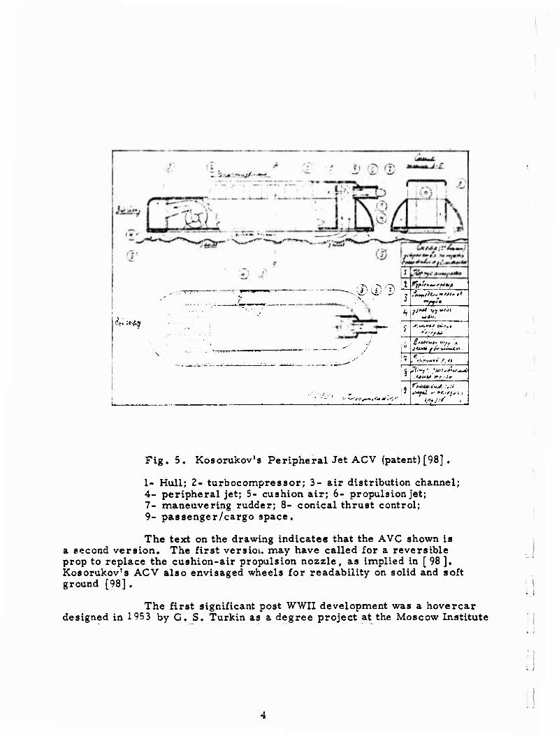
In the early thirties, P. I. Grokhovskoy designed an amphibious wing-in-ground-effect craft (see Fig. 4) which the designer foresaw in the year-round transportation of cargo and passengers at 200-300km/hr along rivers. Although model studies were begun on this craft, pressing requirements to improve military aviation took priority and caused Grokhovskoy's project to be shelved [ 3, 25, 43] .
;
Fig. 4. Grokhovskoy's Amphibious Craft [3] ,
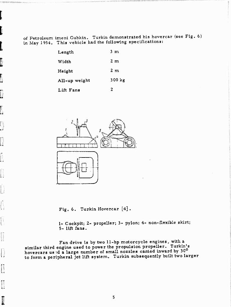
In mid 1950, N. A. Kosorukov patented the peripheral jet ACV shown in Figure 5. This design incorporated a jet canted 45 0 inward to form the cushion. Some cushion air is diverted through a stern nozzle to provide propulsion. A conical throttle controls the thrust, and maneuvering is accomplished by a rudder mounted in the nozzle flow. Unfortunately, there is no indication in the drawing as to how this ACV was to be stopped once in motion.
1
i.-.t ^
i tw '■■ cr ^!A^ lüfe^a j..: -y f***fit***w"»I
lUfrnttm* / >/
/^•■"y '. *M***4Hftiwi n IJHU l*r_-1*
I
Fig. 5. Kosorukov's Peripheral Jet ACV (patent) [98] .
1- Hull; 2- turbocompressor; 3- air distribution channel; 4- peripheral jet; 5- cushion air; 6- propulsion jet; 7- maneuvering rudder; 8- conical thrust control; 9- passenger/cargo space.
The text on the drawing indicate« that the AVC shown is a second version. The first version may have called for a reversible prop to replace the cushion-air propulsion nozzle, as implied in [98]. Kosorukov's ACV also envisaged wheels for readability on solid and soft ground [98].
The first significant post WWII development was a hovercar designed in 1953 by G. S. Türkin as a degree project at the Moscow Institute
..
4
of Petroleum imeni Gubkin. Türkin demonstrated his hovercar (see Fig. 6) in May 1954. This vehicle had the following specifications:
Length 3 m
Width 2 m
Height 2 m
All-up we ight 300 kg
Lift Fans 2
p
Fig. 6. Türkin Hovercar [4],
1- Cockpit; 2- propeller; 3- pylon; 4- non-flexible skirt; 5- lift fans.
Fan drive is by two 11-hp motorcycle engines, with a similar third engine used to power the propulsion propeller. Türkin^s hovercars us -:d a large number of small nozzles canted inward by 30 to form a peripheral jet lift system. Türkin subsequently built two larger
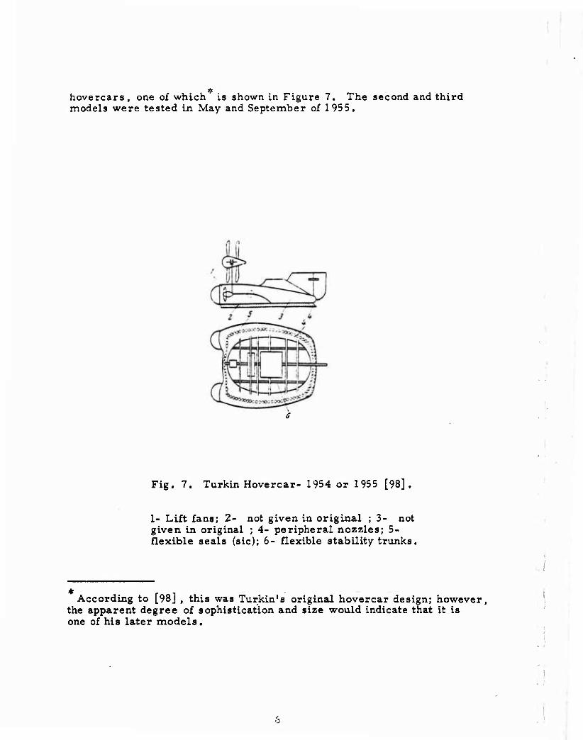
hovercars, one of which is shown in Figure 7. The second and third models were tested in May and September of 1955.
Fig. 7. Türkin Hovercar- 1954 or 1955 [98].
1- Lift fans; 2- not given in original ; 3- not given in original ; 4- peripheral nozzles; 5- flexible seals (sic); 6- flexible stability trunks,
According to [98] , this was Türkin1 s original hovercar design; however, the apparent degree of sophistication and size would indicate that it is one of his later models.
i
I T *
r
:.
:.
In the 195 5 tests, an air gap of 1 cm was achieved over ground and water. According to [74] , this development effort ceased with the premature death of Türkin [4, 64, 72, 74, 98].
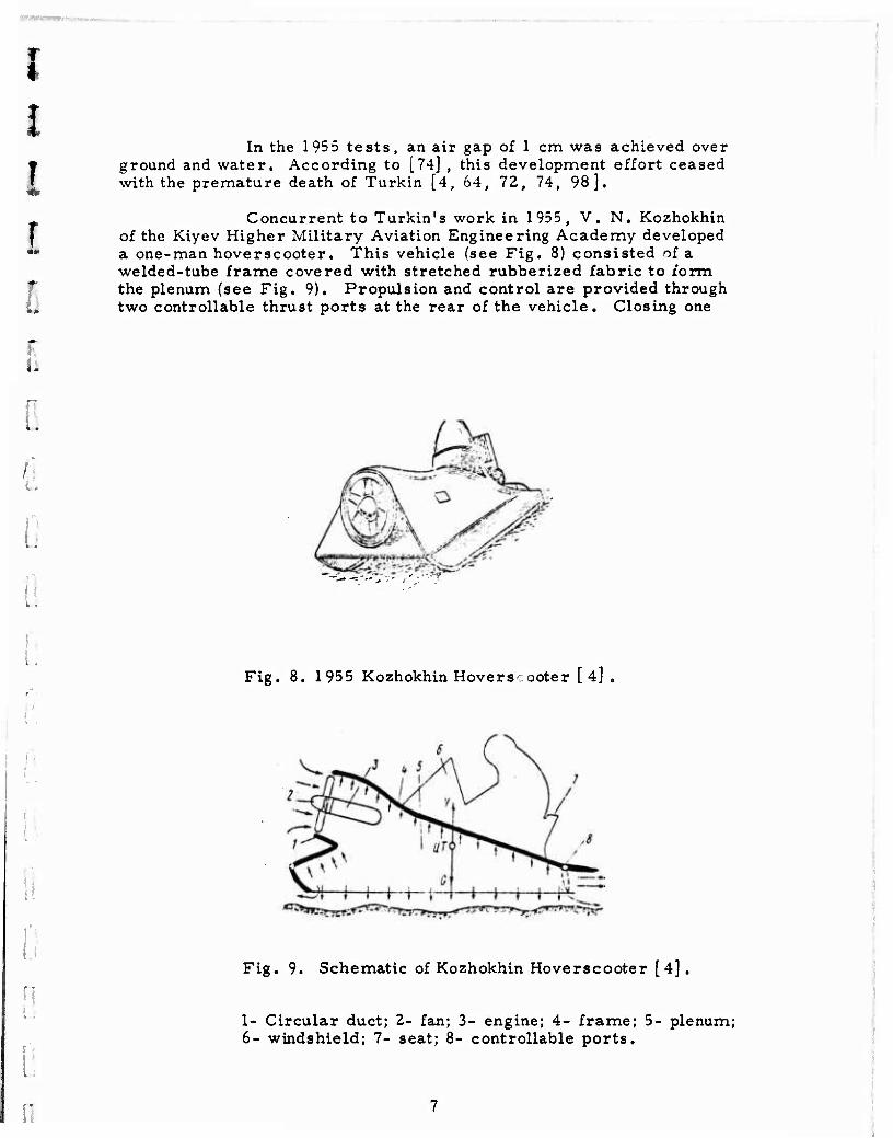
Concurrent to Turkin's work in 1955, V. N. Kozhokhin of the Kiyev Higher Military Aviation Engineering Academy developed a one-man hoverscooter. This vehicle (see Fig. 8) consisted of a welded-tube frame covered with stretched rubberized fabric to form the plenum (see Fig. 9). Propulsion and control are provided through two controllable thrust ports at the rear of the vehicle. Closing one
..
\, *
:
.
I
Fig. 8. 1955 Kozhokhin Hoverscooter [4]
Fig. 9. Schematic of Kozhokhin Hoverscooter [4] .
I- Circular duct; 2- fan; 3- engine; 4- frame; 5- plenum; 6- windshield; 7- seat; 8- controllable ports.
port deflects all the thrust to one side causing the vehicle to turn. Some of the basic specifications of this hoverscooter are:
Length 3 m
Width 2 m
Height 1.5 m
All-up weight 600 kg
Weight empty 500 kg
Cushion pressure lOOkg/m2
Maximum speed 30km/hr
Fan diameter 0.7m
Engine 50 hp
In its 1955 tests, this hoverscooter performed well over snow, mud, water, and marsh. Since the air gap was only several centimeters, the vehicle was subsequently modified with the addition of a flexible shirt to improve its "roadability" over low obstacles [4, 72],
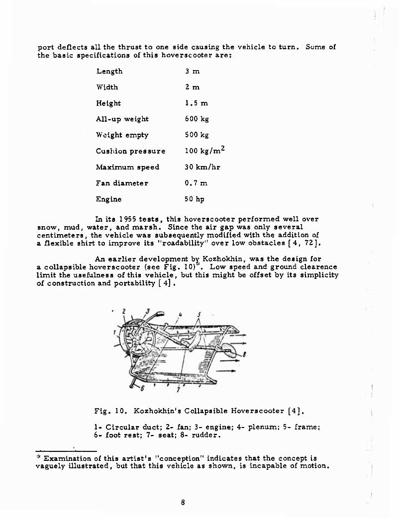
An earlier development by Kozhokhin, was the design for a collapsible hoverscooter (see Fig. 10)^. Low speed and ground clearence limit the usefulness of this vehicle, but this might be offset by its simplicity of construction and portability [ 4] .
Fig. 10. Kozhokhin's Collapsible Hoverscooter [4],
1- Circular duct; 2- fan; 3- engine; 4- plenum; 5- frame; 6- foot rest; 7- seat; 8- rudder.
* Examination of this artist's "conception" indicates that the concept is vaguely illustrated, but that this vehicle as shown, is incapable of motion.
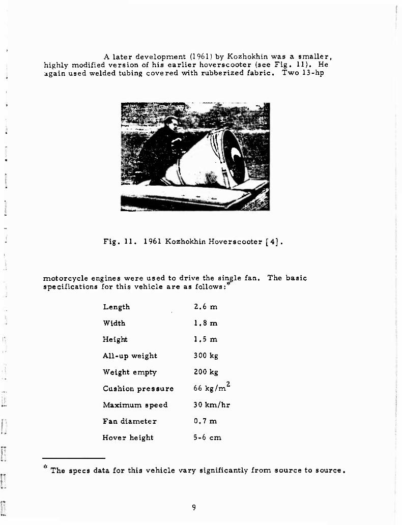
A later development (1961) by Kozhokhin was a smaller, highly modified version of his earlier hoverscooter (see Fig, 11). He again used welded tubing covered with rubberized fabric. Two 13-hp
p*~* "^-4^3^ C ^S|5JMB 3M ̂ ^
i~^~'l^^jBtk t%\ - TKÄJ ]^ ^^H 1 ^Ü^^Jä
a^^^^sssa
Fig. 11. 1961 Kozhokhin Hoverscooter [4].
motorcycle engines were used to drive the single fan. The basic specifications for this vehicle are as follows:
Length
Width
Height
All-up weight
Weight empty
Cushion pressure
Maximum speed
Fan diameter
Hover height
2.6 m
1.8 m
1.5 m
300 kg
200 kg
66 kg/m
30km/hr
0.7 m
5-6 cm
The specs data for this vehicle vary significantly from source to source,
Recommended uses of this vehicle were postal and light cargo hauling in Siberia, the Soviet far north, and the flatlands of Kazakhstan [4, 72, 98, 99, 119].
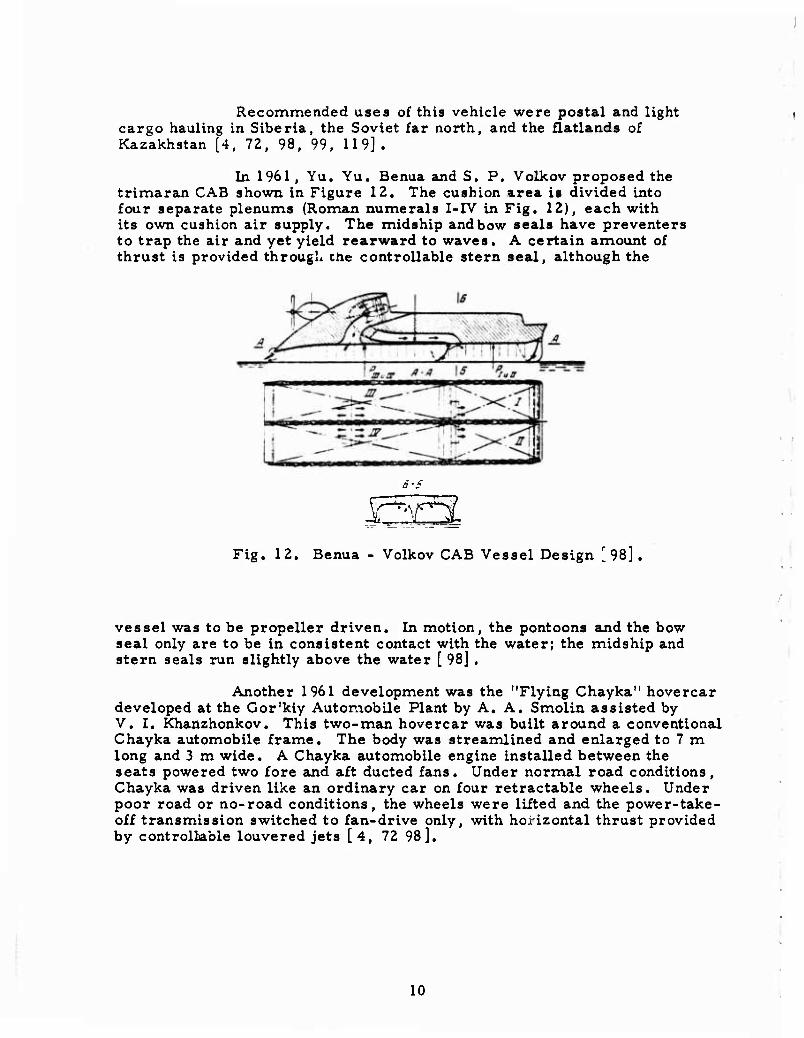
In 1961, Yu. Yu. Benua and S. P. Volkov proposed the trimaran CAB shown in Figure 12. The cushion area is divided into four separate plenums (Roman numerals I-IV in Fig. 12), each with its own cushion air supply. The midship and bow seals have preventers to trap the air and yet yield rearward to waves. A certain amount of thrust is provided through the controllable stern seal, although the
SSI Fig. 12. Benua - Volkov CAB Vessel Design [98].
vessel was to be propeller driven. In motion, the pontoons and the bow seal only are to be in consistent contact with the water; the midship and stern seals run slightly above the water [ 98] .
Another 1961 development was the "Flying Chayka" hovercar developed at the Gor'kiy Automobile Plant by A. A. Smolin assisted by V. I. Khanzhonkov. This two-man hovercar was built around a conventional Chayka automobile frame. The body was streamlined and enlarged to 7 m long and 3 m wide. A Chayka automobile engine installed between the seats powered two fore and aft ducted fans. Under normal road conditions, Chayka was driven like an ordinary car on four retractable wheels. Under poor road or no-road conditions, the wheels were lifted and the power-take- off transmission switched to fan-drive only, with horizontal thrust provided by controllable louvered jets [4, 72 98].
10
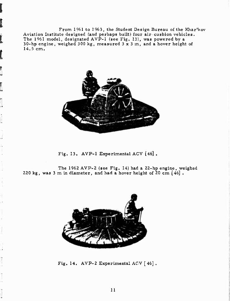
From 1961 to 1963, the Student Design Bureau of the Khar'kov Aviation Institute designed (and perhaps built) four air cushion vehicles. The 1961 model, designated AVP-1 (see Fig. 13), was powered by a 30-hp engine, weighed 300 kg, measured 3x3 m, and a hover height of 14.5 cm.
Fig. 13. AVP-1 Experimental ACV [46] .
The 1962 AVP-2 (see Fig. 14) had a 22-hp engine, weighed 220 kg, was 3 m in diameter, and had a hover height of 20 cm [46] .
Fig. 14. AVP-2 Experimental ACV [ 46] .
11
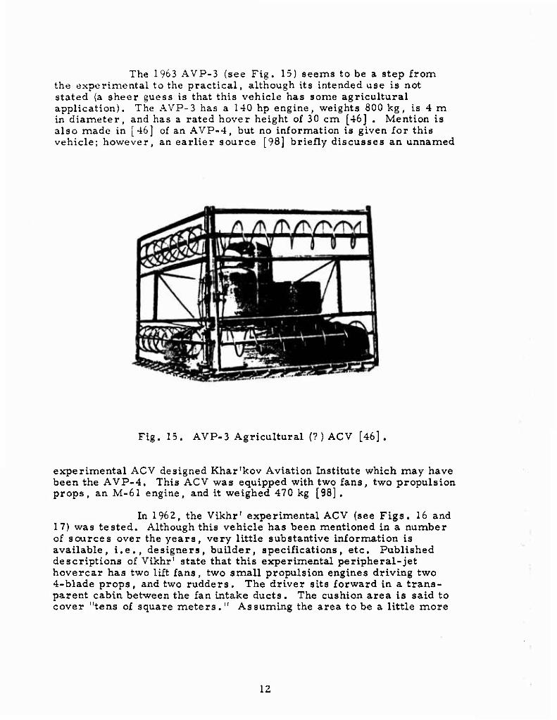
The 1963 AVP-3 (see Fig. 15) seems to be a step from the experimental to the practical, although its intended use is not stated (a sheer guess is that this vehicle has some agricultural application). The AVP-3 has a 140 hp engine, weights 800 kg, is 4 m in diameter, and has a rated hover height of 30 cm [46} . Mention is also made in [46] of an AVP-4, but no information is given for this vehicle; however, an earlier source [98] briefly discusses an unnamed
Fig. 15. AVP-3 Agricultural (? ) ACV [46].
experimental ACV designed Khar'kov Aviation Institute which may have been the AVP-4. This ACV was equipped with two fans, two propulsion props, an M-61 engine, and it weighed 470 kg [98] .
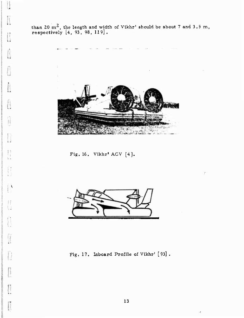
In 1962, the Vikhr' experimental ACV (see Figs. 16 and 17) was tested. Although this vehicle has been mentioned in a number of sources over the years, very little substantive information is available, i.e., designers, builder, specifications, etc. Published descriptions of Vikhr' state that this experimental peripheral-jet hovercar has two lift fans, two small propulsion engines driving two 4-blade props, and two rudders. The driver sits forward in a trans- parent cabin between the fan intake ducts. The cushion area is said to cover "tens of square meters." Assuming the area to be a little more
12
::
11
than 20 m^, the length and width of Vikhr' should be about 7 and 3.5 m, respectively [4, 93, 98, 119].
:; Fig. 16. Vikhr" ACV [4],
Fig. 17. Inboard Profile of Vikhr' [93]
'
13
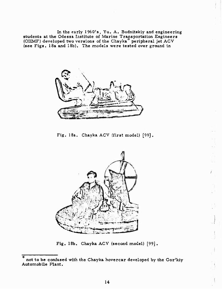
In the early 1960ls, Yu. A. Budnitskiy and engineering students at the Odessa Institute of Marine Transportation Engineers (OIIMF) developed two versions of the Chayka" peripheral jet ACV (see Figs. 18a and 18b). The models were tested over ground in
^ * * - — " ■ _*_ "rl
J^
Fig. 18a. Chayka ACV (first model) [99].
■^^jjfL^--«j;-*- fm
'rmrf»mm^'f*^mmi^i'"'
Fig. 18b. Chayka ACV (second model) [99].
not to be confused with the Chayka hovercar developed by the Gor'kiy Automobile Plant.
14
I I
I •
ii
mid-1963 and although they exhibited good control, stability, and speed, they suffered from engine overheating and low hover height (4-5 cm). Nonavailability of a more powerful, cooler running engine caused shelving of improvements of Chayka, planned for 1964, The basic specifications of Chayka are as follows:
Diameter 2.4 m
Height, o.a. 1.8 m
Total weight 400 kg
Payload 100 kg
Speed 35 knots
Chayka was powered by two 18-hp engines which may have been integrated for lift/propulsion [3, 19, 99].
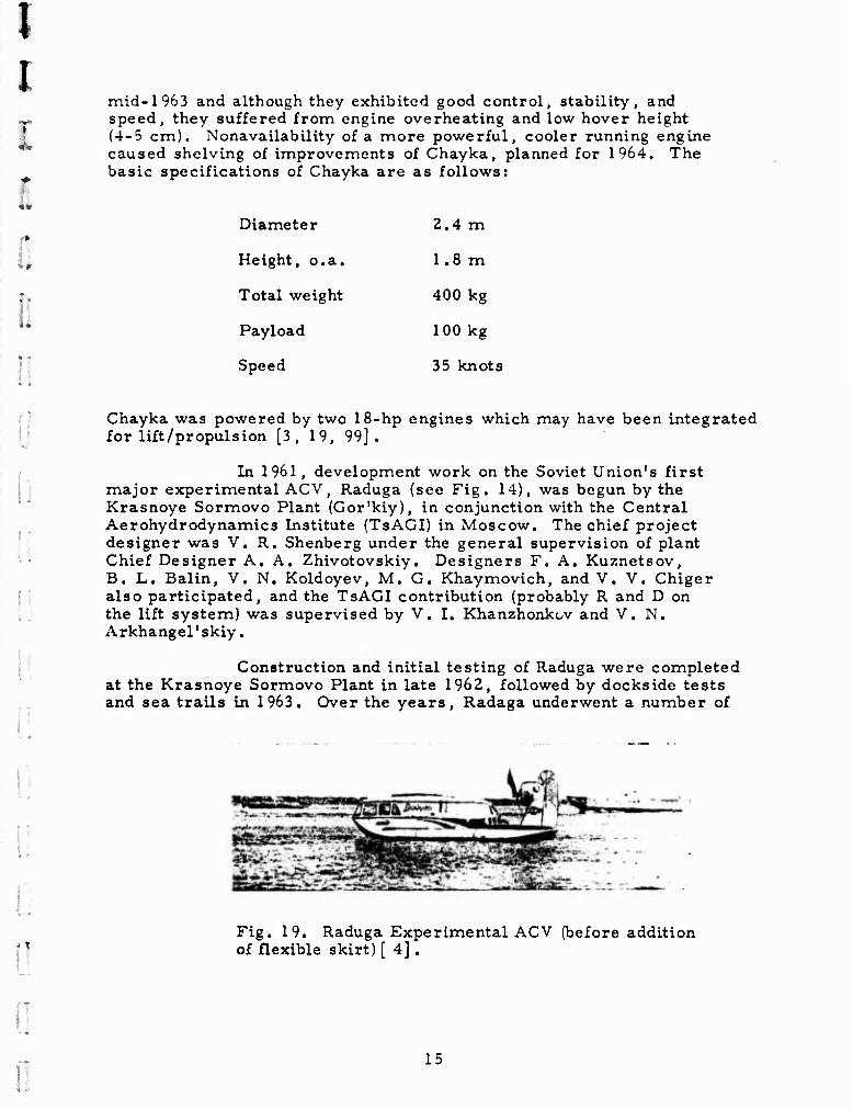
In 1961 , development work on the Soviet Union's first major experimental ACV, Raduga (see Fig. 14), was begun by the Krasnoye Sormovo Plant (Gor'kiy), in conjunction with the Central Aerohydrodynamics Institute (TsAGI) in Moscow. The chief project designer was V.R. Shenberg under the general supervision of plant Chief Designer A. A. Zhivotovskiy. Designers F. A. Kuznetsov, B. L. Balin, V. N. Koldoyev, M. G. Khaymovich, and V. V. Chiger also participated, and the TsAGI contribution (probably R and D on the lift system) was supervised by V. I. Khanzhonkov and V. N. Arkhangel'skiy,
Construction and initial testing of Raduga were completed at the Krasnoye Sormovo Plant in late 1962, followed by dockside tests and sea trails in 1963. Over the years, Radaga underwent a number of
Fig. 19. Raduga Experimental ACV (before addition of flexible skirt) [ 4] .
15
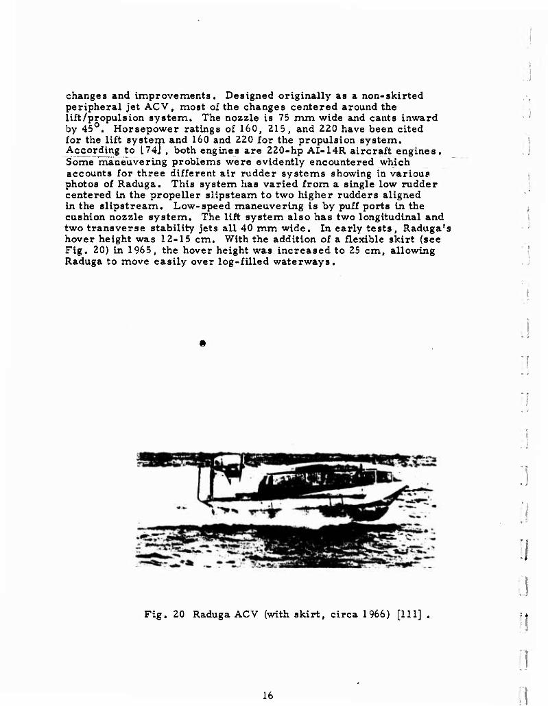
changes and improvements. Designed originally as a non-skirted peripheral jet ACV, most of the changes centered around the lift/propulsion system. The nozzle is 75 mm wide and cants inward by 45 , Horsepower ratings of 160, 215, and 220 have been cited for the lift system and 160 and 220 for the propulsion system. According to L74J , both engines are 220-hp AI-14R aircraft engines. Some maneuvering problems were evidently encountered which accounts for three different air rudder systems showing in various photos of Raduga. This system has varied from a single low rudder centered in the propeller slipsteam to two higher rudders aligned in the slipstream. Low-speed maneuvering is by puff ports in the cushion nozzle system. The lift system also has two longitudinal and two transverse stability jets all 40 mm wide. In early tests, Raduga's hover height was 12-15 cm. With the addition of a flexible skirt (see Fig. 20) in 1965, the hover height was increased to 25 cm, allowing Raduga to move easily over log-filled waterways.
Fig. 20 Raduga ACV (with skirt, circa 1966) [111] .
.:
16
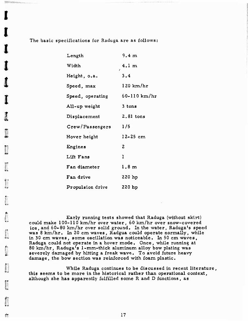
The basic specifications for Raduga are as follows:
Length 9.4 m
Width 4.1 m
Height, o.a. 3.4
Speed, max 120 km/hr
Speed, operating 60-110 km/hr
All-up weight 3 tons
Displacement 2. 81 tons
Crew/Passengers 1/5
Hover height 12-25 cm
Engines 2
Lift Fans 1
Fan diameter 1.8 m
Fan drive 220 hp
Propulsion drive 220 hp
II
Early running tests showed that Raduga (without skirt) could make 100-110 km/hr over water, 60 km/hr over snow-covered ice, and 60-80 km/hr over solid ground. In the water, Raduga's speed was 8 km/hr. In 20 cm waves, Radgua could operate normally, while in 30 cm waves, some oscillation was noticeable. In 50 cm waves, Raduga could not operate in a hover mode. Once, while running at 80 km/hr, Raduga's 1-mm-thick aluminum alloy bow plating was severely damaged by hitting a freak wave. To avoid future heavy damage, the bow section was reinforced with foam plastic.
While Raduga continues to be discussed in recent literature, this seems to be more in the historical rather than operational context, although she has apparently fulfilled some R and D functions, as
- 17
mentioned in [ill] and the 1973-74 Jane's Surface Skimmers [4, 12, 17. 56. 64, 72, 73. 74. 98. 99. 111. and 119J .
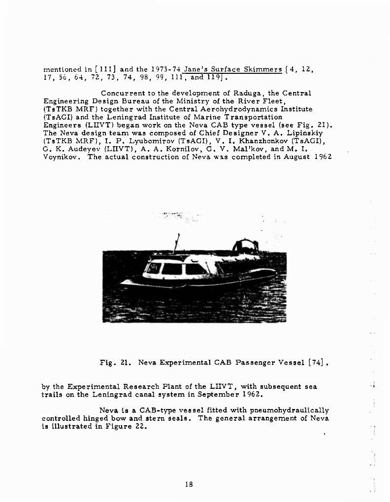
Concurrent to the development of Raduga, the Central Engineering Design Bureau of the Ministry of the River Fleet, (TsTKB MRF) together with the Central Aerohydrodynamics Institute (TsAGI) and the Leningrad Institute of Marine Transportation Engineers (LIIVT) began work on the Neva CAB type vessel (see Fig. 21). The Neva design team was composed of Chief Designer V. A. Lipinskiy (TsTKB MRF), I. P. Lyubomirov (TsAGI), V. I. Khanzhonkov (TsAGI), G. K. Audeyev (LIIVT), A. A. Kornilov, G. V. Mal'kov, and M. I. Voynikov. The actual construction of Neva was completed in August 1962
"-
Fig. 21. Neva Experimental CAB Passenger Vessel [74] .
by the Experimental Research Plant of the LIIVT, with subsequent sea trails on the Leningrad canal system in September 1962.
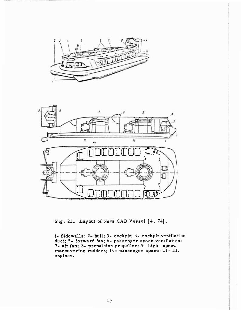
Neva is a CAB-type vessel fitted with pneumohydraulically controlled hinged bow and stern seals. The general arrangement of Neva is illustrated in Figure 22.
.
18
g'üüraOT^
^(DmEDEEms fag^
Fig. 22. Layout of Neva CAB Vessel [4, 74] .
1- Sidewalls; 2- hull; 3- cockpit; 4- cockpit ventilation duct; 5- forward fan; 6- passenger space ventilation; 7- aft fan; 8- propulsion propeller; 9- high- speed maneuvering rudders; 10- passenger space; 11- lift engines.
19
The basic specifications for Neva are as follows;
Length
Width
Height, o.a.
Height (superstructure)
Cruising speed
Speed, max
Cruising range
All-up weight, max
Crew/passengers
Hover height
Engines, total
Lift fans
Fan diameter
Fan drive
Total fan capacity
Propulsion drive
Cushion area
Cushion pressure
17.3 m
6,6 m
4.1 m
2.6 m
25 knots
60 km/hr
120 nm
12.45 tons
2/38
5-8 cm
3
2
2 m
2 x 220 hp
2 x 55 m /sec
285 hp
87 m2
143 kg/m2
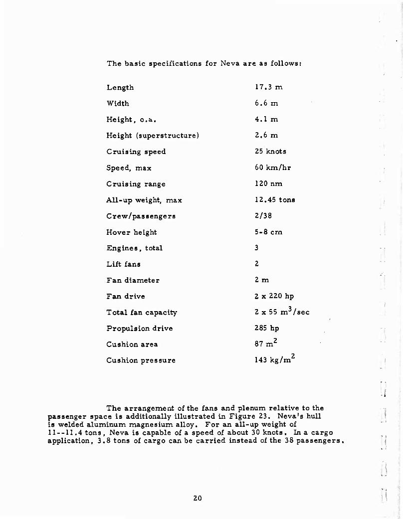
The arrangement of the fans and plenum relative to the passenger space is additionally illustrated in Figure 23. Neva's hull is welded aluminum magnesium alloy. For an all-up weight of 11--11.4 tons, Neva is capable of a speed of about 30 knots. In a cargo application, 3.8 tons of cargo can be carried instead of the 38 passengers.
I
20
•*
:
.:
Fig. 23. Neva Fan/Plenum. Arrangement [4].
;
1- Sidewalls; 2- spray deflector; 3- plenum; 4- passenger space; 5- air duct; 6- fan engine; 7- fan; 8- air rudders; 9- propulsion engine; 10- propulsion propeller; 11- propeller shroud.
i:
0
il
To >jsist in low-speed maneuvering and docking, Neva is equipped with two retractable water rudders operating with the air rudders and controlled by the same steering column.
Early references [4, 72, 73], state that the propulsion engine was rated at 220 hp. This engine was apparently replaced by a 285-hp engine. A later reference [74] states that poor seaworthiness, low thrust, inadequate maneuvering with the air rudders, and a high degree of spray generation prevented Neva from going into lot production. Recent use of Neva is not evident from the literature [4, 64, 72, 73, 74, 119, and 120].
As reported in the early to mid 1960^ Moscow Aviation Institute (MAI) was Involved in the design of a variety of surface effect craft. The first of these is a large cargo SES (see Fig. 24) weighing 40 tons and designed to carry a 20-ton load. Judging from the model, propulsion is probably provided by thrust deflection from some or all of the eight ducted lift fans [4].
-.
21
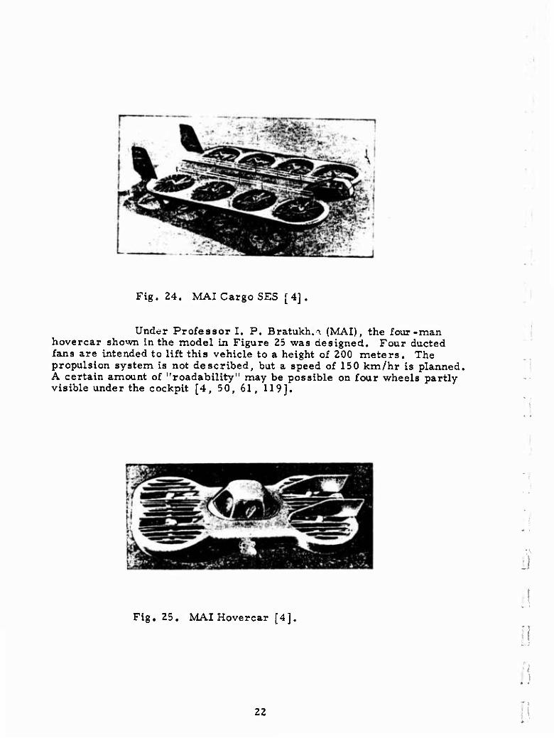
Fig. 24. MAI Cargo SES [4].
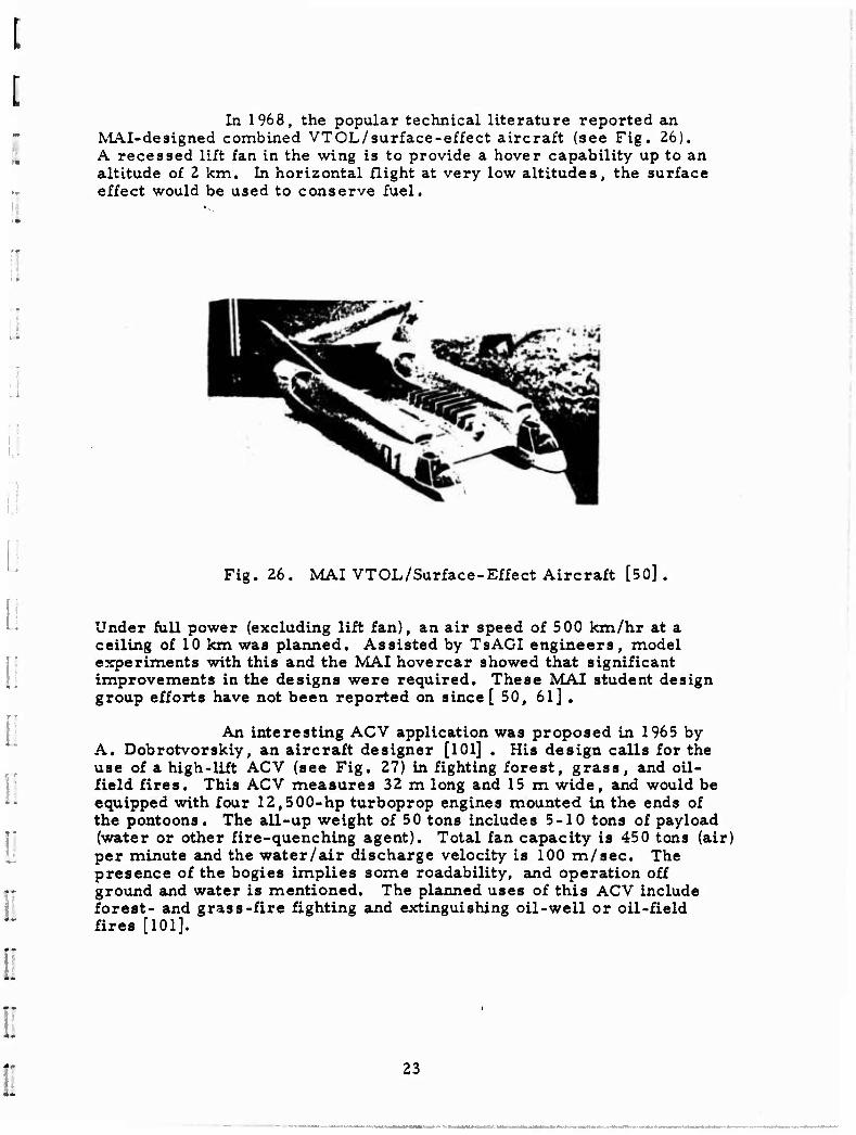
Under Professor I. P. Bratukh.i (MAI), the four-man hovercar shown in the model in Figure 25 was designed. Four ducted fans are intended to lift this vehicle to a height of 200 meters. The propulsion system is not described, but a speed of 150 km/hr is planned, A certain amount of "roadability" may be possible on four wheels partly visible under the cockpit [4, 50, 61, 119].
* •
Fig. 25. MAI Hovercar [4].
22
Ü
In 1968, the popular technical literature reported an MAI-designed combined VTOL/surface-effect aircraft (see Fig. 26). A recessed lift fan in the wing is to provide a hover capability up to an altitude of 2 km. In horizontal flight at very low altitudes, the surface effect would be used to conserve fuel.
Fig. 26. MAI VTOL/Surface-Effect Aircraft [50] .
Under full power (excluding lift fan), an air speed of 500 km/hr at a ceiling of 10 km was planned. Assisted by TsAGI engineers, model experiments with this and the MAI hovercar showed that significant improvements in the designs were required. These MAI student design group efforts have not been reported on since [50, 61] .
An interesting ACV application was proposed in 1965 by A. Dobrotvorskiy, an aircraft designer [101] . His design calls for the use of a high-lift ACV (see Fig, 27) in fighting forest, grass, and oil- field fires. This ACV measures 32 m long and 15 m wide, and would be equipped with four 12,500-hp turboprop engines mounted in the ends of the pontoons. The all-up weight of 50 tons includes 5-10 tons of payload (water or other fire-quenching agent). Total fan capacity is 450 tons (air) per minute and the water/air discharge velocity is 100 m/sec. The presence of the bogies implies some readability, and operation off ground and water is mentioned. The planned uses of this ACV include forest- and grass-fire fighting and extinguishing oil-well or oil-field fires [101].
23
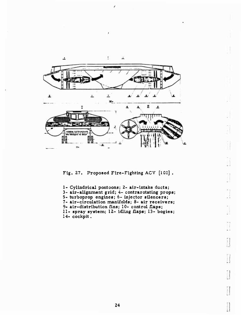
Fig. 27. Proposed Fire-Fighting ACV [101] .
I- Cylindrical pontoons; 2- air-intake ducts; 3- air-alignment grid; 4- contrarotating props; 5- turboprop engines; 6- injector silencers; 7- air-circulation manifolds; 8- air receivers; 9- air-distribution fins; 10- control flaps; II- spray system; 12- idling flaps; 13- bogies; 14- cockpit.
Ö
24
il
MMpWuw ■ • ■■ . . ■
PART II. OPERATIONAL SURFACE EFFECT VEHICLES
A. SOVIET UNION
1 . Air-Cushion Vehicles
Sormovich
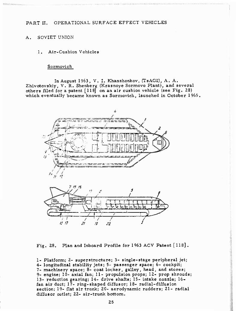
In August 1963, V. I. Khanzhonkov, (TsAGI), A. A. Zhivotovskiy, V.R. Shenberg (Krasnoye Sormovo Plant), and several others filed for a patent [118] on an air cushion vehicle (see Fig. 28) which eventually became known as Sormovich, launched in October 1965.
... yf\
:j
"'
3
-A ^_JL ^lo ,... mn~prrrTT~i.r7if
T
'S 17 21 !9 22
3 /
Fig. 28. Plan and Inboard Profile for 1963 ACV Patent [ 118] .
1- Platform; 2- superstructure; 3- single-stage peripheral jet; 4- longitudinal stability jets; 5- passenger space; 6- cockpit; 7- machinery space; 8- coat locker, galley, head, and stores; 9- engine; 10- axial fan; 11- propulsion props; 12- prop shrouds; 13- reduction gearing; 14- drive shafts; 15- intake nozzle; 16- fan air duct; 17- ring-shaped diffusor; 18- radial-diffusion section; 19- flat air trunk; 20- aerodynamic rudders; 21- radial diffusor outlet; 22- air-trunk bottom.
25
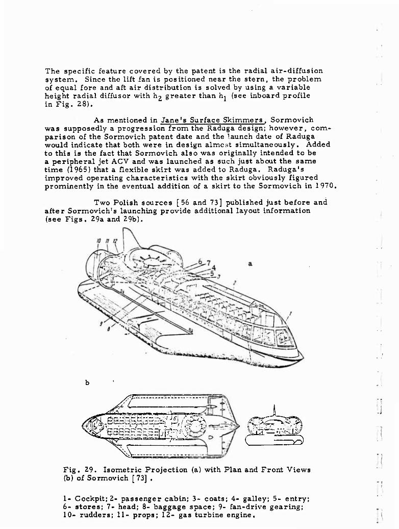
The specific feature covered by the patent is the radial air-diffus ion system. Since the lift fan is positioned near the stern, the problem of equal fore and aft air distribution is solved by using a variable height radial diffusor with l^ greater than h^ (see inboard profile in Fig. 28).
As mentioned in Jane's Surface Skimmers, Sormovich was supposedly a progression from the Raduga design; however, com- parison of the Sormovich patent date and the launch date of Raduga would indicate that both were in design almost simultaneously. Added to this is the fact that Sormovich also was originally intended to be a peripheral jet ACV and was launched as such just about the same time (1965) that a flexible skirt was added to Raduga. Raduga's improved operating characteristics with the skirt obviously figured prominently in the eventual addition of a skirt to the Sormovich in 1970,
Two Polish sources [56 and 73] published just before and after Sormovich's launching provide additional layout information (see Figs. Z9a and 29b).
'L
tfmnea 'r ■ i-l—i-tJ 7—'—-^-
Fig. 29. Isometric Projection (a) with Plan and Front Views (b) of Sormovich [73] .
1- Cockpit; 2- passenger cabin; 3- coats; 4- galley; 5- entry; 6- stores; 7- head; 8- baggage space; 9- fan-drive gearing; 10- rudders; 11- props; 12- gas turbine engine.
:
o
- • -
• ■
I
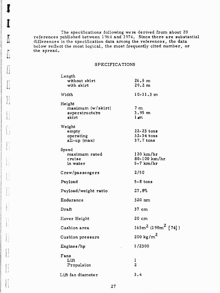
The specifications following were derived from about 20 references published between 1964 and 1974. Since there are substantial
«- differences in the specification data among the references, the data below reflect the most logical, the most frequently cited number, or
f the spread. I
SPECIFICATIONS
Length
! .
:
n
without skirt with skirt
26.5 m 29.2 m
Width 10-11.3 m
Height maximum (w/skirt) superstructure skirt
7 m 3.95 m 1 «m
Weight empty operating all-up (max)
22-23 tons 32-34 tons 37.7 tons
Speed maximum rated cruise in water
120 km/hr 80-100 km/hr 5-7 km/hr
Crew/passengers 2/50
Payload 5-8 tons
Payload/weight ratio 27.8%
Endurance 320 nm
Draft 37 cm
Mover Height 20 cm
Cushion area 165m2 (190m2 [74]
Cushion pressure 200 kg/m2
Engine s/hp 1/2300
Fans Lift Propulsion
1 2
Lift fan diameter 3.4
27
The initial tests of Sormovich in 1965 were over a concrete pad, followed by "wet" tests on the Volga. According to Soviet popular sources, at least two and perhaps three or more series of tests were run subsequent to 1965. The first of these was in 196 9 or 1970, probably following the installation of the flexible skirt and the possible installation of a new lift/propulsion engine. The second known series of tests occurred on the Volga in March 1973, and involved extensive operation over snow covered ice to determine maneuvering and obstacle avoidance capabilities, based on procedures developed by the Gor'kiy Institute of Marine Transportation Engineers (GIIVT). The test site was in an area where the river ranged from 200 to 700 m wide, with half-meter-high ice hummocks and polynyas. Snow cover on the ice was 30 to 50 cm. In the tests, Sormovich was able to avoid large hummocks by 60 meters when spotted from a distance of 400-500 m, using the air rudders only. The tests also include study of possible icing of the skirt leading to its rupture; however, no damaging effects were noticed. Over the ice, Sormovich tended to accelerate faster than over water. It was also noted that in an emergency set-down due to loss of lift, Sormovich decelerated quickly without sudden loss of cushion pressure and without damage. The tests over ice did show that some minor (unspecified) structural changes in Sormovich were required to make her more "ice worthy" [18],
In 1970, it was reported that the Commission on Inventions and Discoveries recommended to the USSR State Planning Commisibn that lot production of Sormovich ACV's be initiated by the Ministry of Shipbuilding. There is no indication that this recommendation has been acted upon. Although Jane's considers the Sormovich to have evolved into an economically viable vehicle, it somehow seems unlikely that the Soviets would gear up a production capacity for a 10-year old vehicle, particularly when 50-passenger versions of fully amphibious military ACV's are apparently going to be "civilianized." Here, an existing production capability already exists. Added to this is the fact that civilian versions of military ACV's could easily be reconverted in the event of armed conflict. The performance characteristics of the military ACV1 s should be higher than those of Sormovich, although their probable higher cost could be an offsetting factor. Finally, according to [94] , GIIVT is presently designing a 150-passenger, 150-km/hr ACV, possibly to "replace" the one-of-a-kind Sormovich [ 3, 4, 12, 17, 18, 23, 39, 42, 44, 45, 49, 56, 62, 64, 73, 74, 94, 118, 145, 146, 147] .
Navy ACV-1967
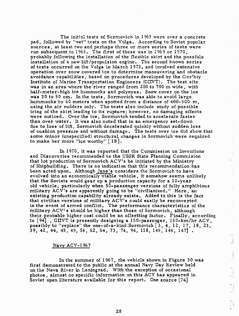
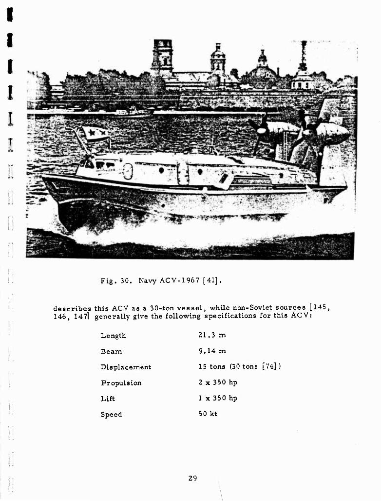
In the summer of 1967, the vehicle shown in Figure 30 was first demonstrated to the public at the annual Navy Day Review held on the Neva River in Leningrad. With the exception of occasional photos , almost no specific information on this ACV has appeared in I. Soviet open literature available for this report. One source [74]
li
28
I I I I 1
i! Fig. 30. Navy ACV-1967 [41].
describes this ACV as a 30-ton vessel, while non-Soviet sources [145, 146, 147] generally give the following specifications for this ACV:
Length
Beam
Displacement
Propulsion
Lift
Speed
21.3 m
9.14 m
15 tons (30 tons [74] )
2 x 350 hp
1 x 350 hp
50 kt
1
29
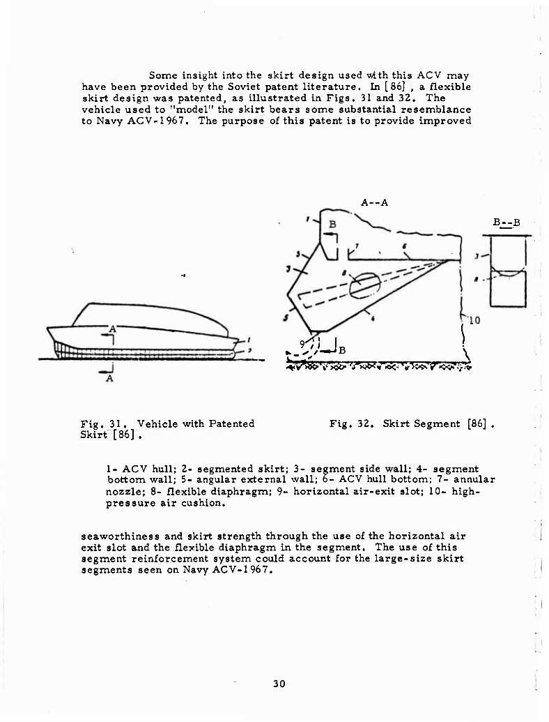
Some insight into the skirt design used with this ACV may have been provided by the Soviet patent literature. In [86] , a flexible skirt design was patented, as illustrated in Figs. 31 and 32. The vehicle used to "model" the skirt bears some substantial resemblance to Navy ACV-1967. The purpose of this patent is to provide improved
A--A
B--B
9^UB l
Fig. 31. Vehicle with Patented Skirt [86] .
Fig. 32. Skirt Segment [86]
1- ACV hull; 2- segmented skirt; 3- segment side wall; 4- segment bottom wall; 5- angular external wall; o- ACV hull bottom; 7- annular nozzle; 8- flexible diaphragm; 9- horizontal air-exit slot; 10- high- pressure air cushion.
seaworthiness and skirt strength through the use of the horizontal air exit slot and the flexible diaphragm in the segment. The use of this segment reinforcement system could account for the large-size skirt segments seen on Navy ACV-1967.
30
Navy ACV-1969 ("Gus1
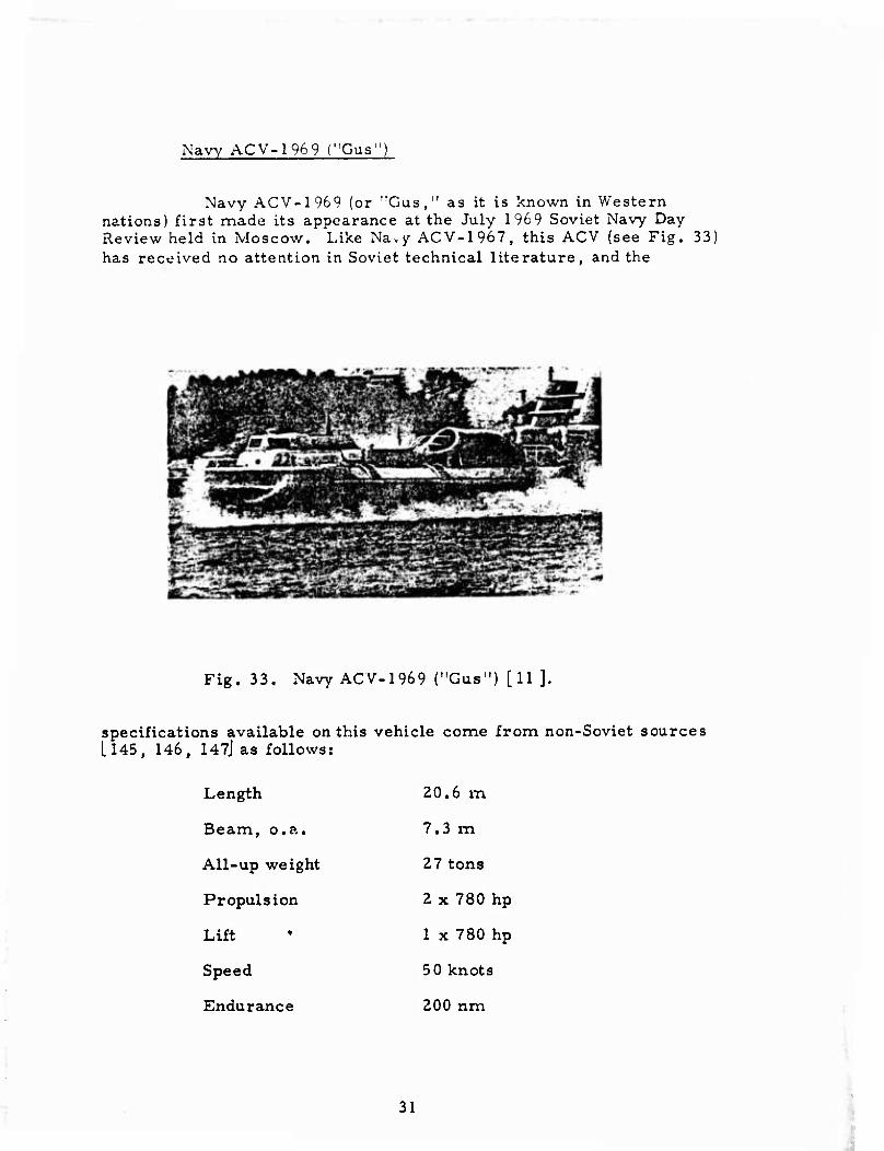
Navy ACV-1969 (or "Gus ," as it is known in Western nations) first made its appearance at the July 1969 Soviet Navy Day Review held in Moscow. Like Navy ACV-1967, this ACV (see Fig. 33) has received no attention in Soviet technical literature, and the
Fig. 33. Navy ACV-1969 ("Gus") [11 ],
specifications available on this vehicle come from non-Soviet sources [l45, 146, 147J as follows:
Length
Beam, o.a.
All-up weight
Propulsion
Lift
Speed
Endurance
20.6 m
7.3 m
27 tons
2 x 780 hp
1 x 780 hp
5 0 knots
200 nm
31
Both propulsion and lift are provided by TVD-10 marine gas-turbine engines [11, 145, 146, 147] .
Navy ACV-1975
Nothing has appeared in Soviet technical or popular literature on the Soviet Navy's largest air-cushion vehicle, although mention of this ACV has appeared previously in Western journals [ 146, 148], These sources describe the vehicle as a 180-200-ton vehicle similar to the British Navy's SR.N4. A photo appearing in Aviation Week and Space Technology'1 bears out the description, with the major apparent difference being the spacing between the propulsion engine pylons. With the"cat out of the bag", it is hoped that the Soviets will now provide greater insight into their ACV development programs.
Briz
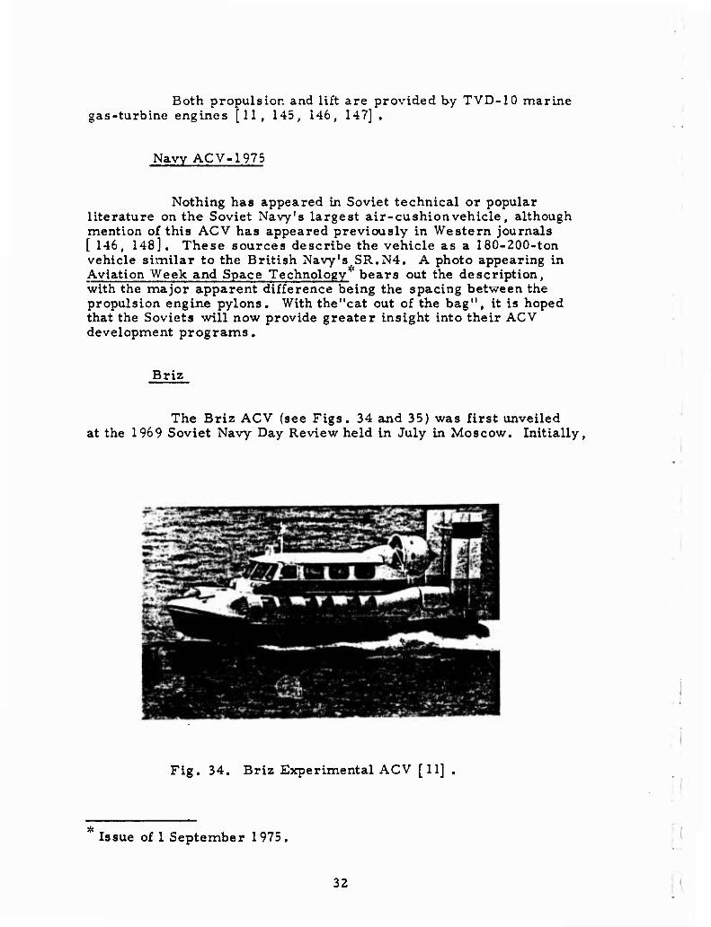
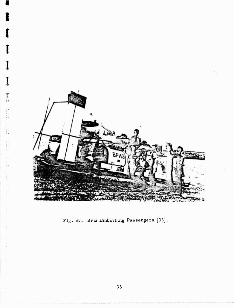
The Briz ACV (see Figs. 34 and 35) was first unveiled at the 1969 Soviet Navy Day Review held in July in Moscow. Initially,
3s^'S^>^amMmh^i*s
Fig. 34. Briz Experimental ACV [11] .
Issue of 1 September 1975.
32
I
I f (
I !
f
:.
Fig. 35. Briz Embarking Passengers [33] .
33
■
no specific information was available on Briz, and it was assumed to be another experimental Navy ACV. By 1972-73, it appeared that any Navy interest in Briz had waned and it was now a one-of-a-kind craft used for show and as the subject o^. infrequent brief magazine articles. In 1973, Briz's design was attributed to a volunteer design group headed by G. Koronatov, a graduate of Leningrad Shipbuilding Institute. The basic specifications available for Briz are as follows:
Length (approximate) 9 m
Weight 4 tons
Hover Height 10-50 cm
Speed 100 km/hr
Passengers/Load 10/1 ton
Briz's propulsion is provided by a flight de-rated radial engine from a YaK-18 competition aircraft. Lift is generated by two sets of four centrifugal fans driven by two water-cooled Moskvich-407 automobile engines. The lift engines are located aft, under the name- plate cowlings, and the fans are housed in the vented tunnels running along the sides. Two aerodynamic rudders and fore and aft puff ports are used for maneuvering.
Briz's cab and engine were apparently taken intact from a KA-30 air sled. It appears that the skis were simply removed from the KA-30 and the remaining vehicle was just bolted to an air cushion platform fitted with air rudders. As late as August 1973, reports were stating that Briz was still undergoing testing [ll, 20, 24, 33, 113] .
Khar'kov Aviation Institute ACV
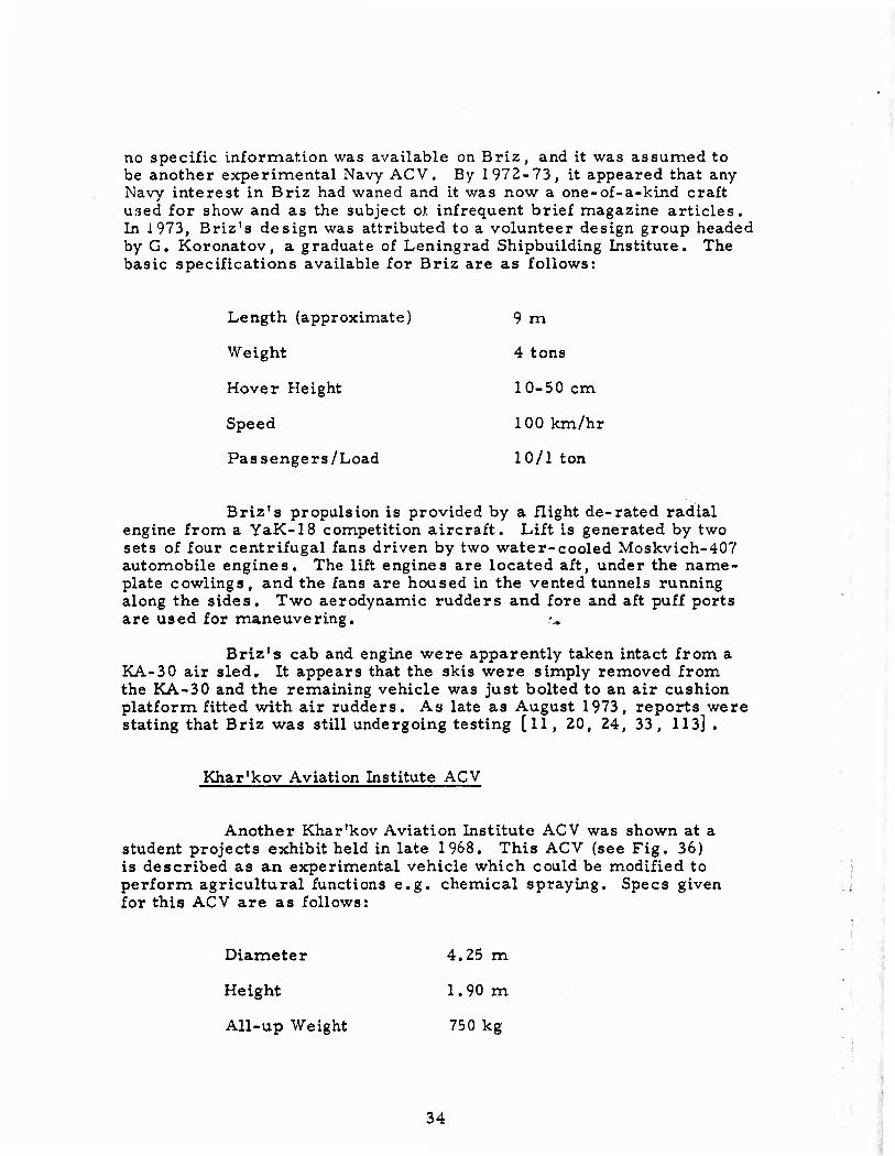
Another Khar'kov Aviation Institute ACV was shown at a student projects exhibit held in late 1968. This ACV (see Fig. 36) is described as an experimental vehicle which could be modified to perform agricultural functions e.g. chemical spraying. Specs given for this ACV are as follows:
Diameter 4.25 m
Height 1. 90 m
All-up Weight 750 kg
34
Hover height
Fan diameter
Cushion pressure
20 cm
1.5m
60 kg/m2
•"•
Fig. 36. Khar'kov Aviation Institute ACV [ 108] .
This ACV has an integrated lift and propulsion system which operates off a 140-hp M332 engine driving two-blade propulsion props and a centrifugal lift fan [ 38, 47, 57, 108],
Skat
• i"
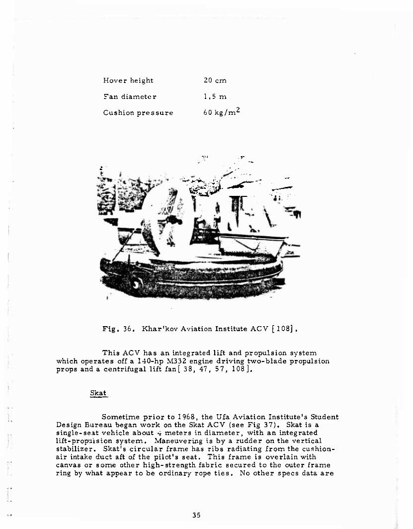
Sometime prior to 1968, the Ufa Aviation Institute's Student Design Bureau began work on the Skat ACV (see Fig 37). Skat is a single-seat vehicle about 4 meters in diameter, with an integrated lift-propaision system. Maneuvering is by a rudder on the vertical stabilizer. Skat's circular frame has ribs radiating from the cushion- air intake duct aft of the pilot's seat. This frame is overlain with canvas or some other high-strength fabric secured to the outer frame ring by what appear to be ordinary rope ties. No other specs data are
35
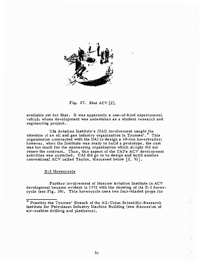
Fig. 37. Skat ACV [2].
available yet for Skat. It was apparently a one-of-kind experimental vehicle whose development was undertaken as a student research and engineering project.
Ufa Aviation Institute's (UAI) involvement caught^he attention of an oil and gas industry organization in Tyumen'. 5 This organization contracted with the UAI to design a 40-ton hovertrailer; however, when the Institute was ready to build a prototype, the cost was too much for the sponsoring organization which simply did not renew the contract. Thus , this aspect of the UAI's ACV development activities was curtailed. UAI did go on to design and build another conventional ACV called Tayfun, discussed below [2, 91] .
X-3 Hovercycle
Further involvement of Moscow Aviation Institute in ACV development became evident in 1972 with the showing of its X-3 hover- cycle (see Fig. 38). This hovercycle uses two four-bladed props for
Possibly the Tyumen' Branch of the All-Union Scientific-Research Institute for Petroleum Industry Machine Building (see discussion of air-cushion drillrig and platforms).
3o
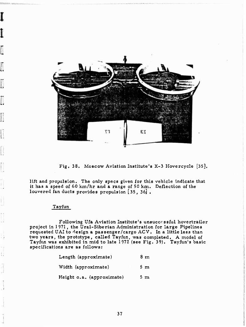
Fig. 38. Moscow Aviation Institute's X-3 Hovercycle [35],
lift and propulsion. The only specs given for this vehicle indicate that it has a speed of 60 km/hr and a range of 50 km. Deflection of the louvered fan ducts provides propulsion [35, 36] .
T ay fun
Following Ufa Aviation Institute's unsuccessful hovertrailer project in 1971, the Ural-Siberian Administration for large Pipelines requested UAI to design a passenger/cargo ACV, In a little less than two years, the prototype, called Tayfun, was completed. A model of Tayfun was exhibited in mid to late 1972 (see Fig. 39). Tayfun's basic specifications are as follows:
Length (approximate) 8 m
Width (approximate) 5 m
Height o.a. (approximate) 5 m
37
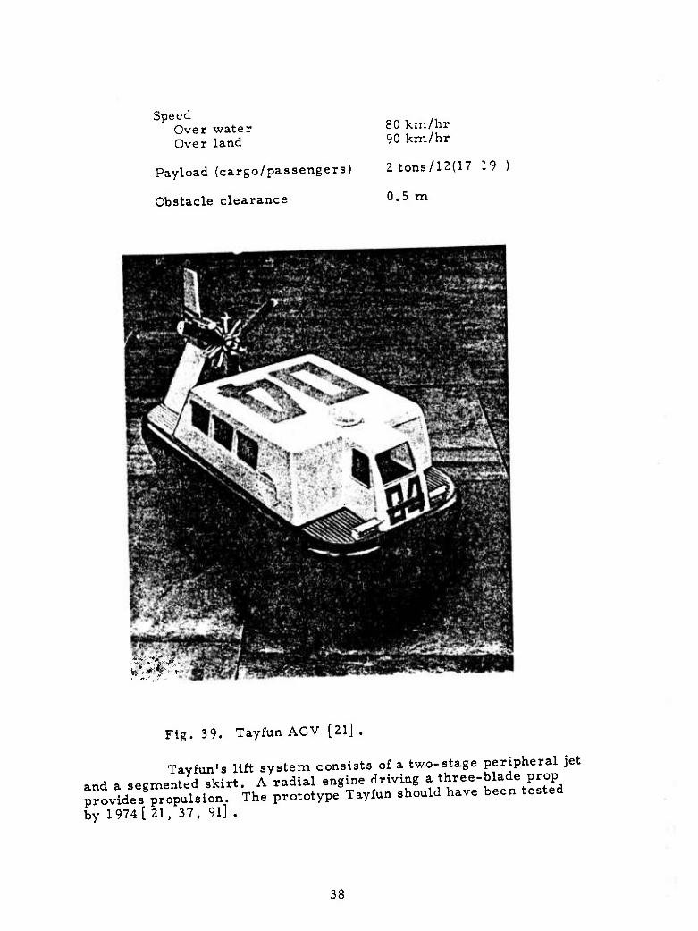
Speed Over water Over land
Payload (cargo/passengers)
Obstacle clearance
80 km/hr 90 km/hr
2tons/12(17 19 )
0.5 m
Fig. 3 9. Tayfun ACV [21] .
Tayfun's lift system consists of a two-stage peripheral jet and a segmented skirt. A radial engine driving a three-blade prop provides propulsion. The prototype Tayfun should have been tested by 1974 [21. 37, 9l] .
38
2. Rigid Sidewall ACV's
Modern rigid sidewall ACV's have been under design in the Soviet Union since 1961, when cooperative efforts were initiated by the Volgabaltsudoproyekt Design Bureau and the Gor'kiy Institute of Marine Transportation Engineers (GIIVT). Early joint design efforts produced several operating models, including a 3-ton, 10-passenger vehicle, built in 1963 as the prototype of the Gor'kovchanin rigid sidewall water bus described below. The prototype had the following specifications:
Length 9.6 m
Beam 3.6 m
Height 1.4 m
Cushion area 8. 5 x 3. 2 m
Lift and propulsion are provided by three Volga automobile engines. A single engine drives the horizontal centrifugal fan (similar to Briz) which provides lift through 6-cm wide bow and stern nozzle slits set at 45° in the bow and stern. The sidewall and center skeg are 20 cm high. Propulsion is by the two remaining Volga engines arranged as ducted prop units on the deck. The following three seal systems were tested: 1) a single flexible bow seal; 2) two-stage annular bow and stern jets; and 3) flexible bow and center-frame seals. In the first case, speeds of 40-45 km/hr were attained under varying load conditions. With the second arrangement, the speed reached 30-32 km/hr. Using the last system, the speed initially was better than the second system; however, the speed dropped off sharply as the load was increased [29].
Two other vessels on the GIIVT drawing boards are a 66-m-long, 12-m wide 150-passenger rigid sidewall vessel capable 60 km/hr, powered by a 5000-hp diesel, and a 400 ton vessel* capable of carrying a 170-ton load at about 30 knots [74, 88].
Gor'kovchanin (Zarnitsa)
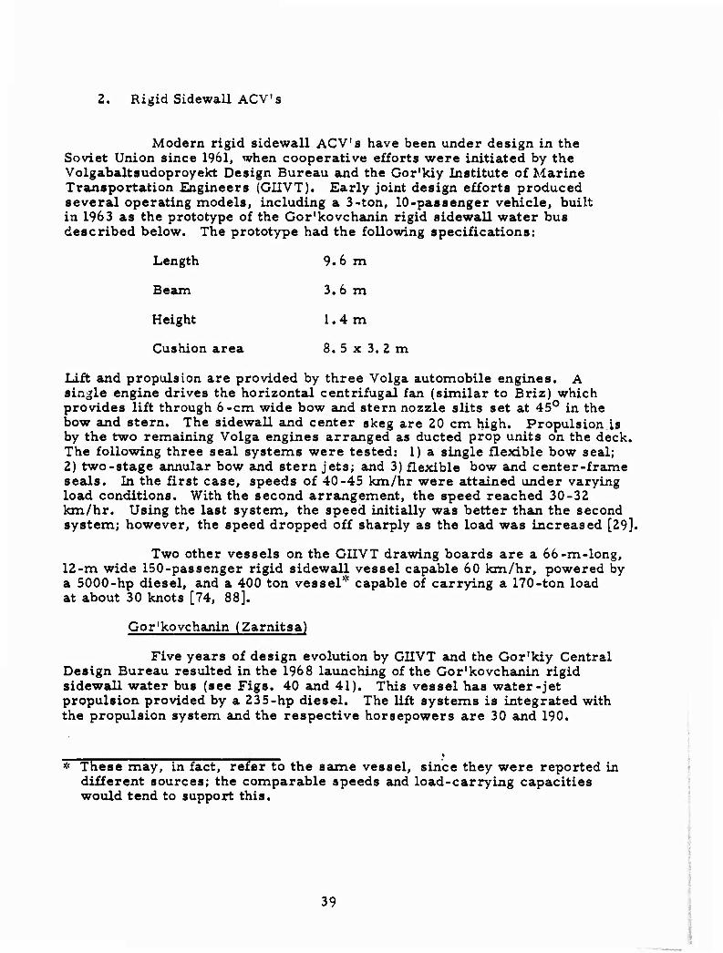
Five years of design evolution by GIIVT and the Gor'kiy Central Design Bureau resulted in the 1968 launching of the Gor'kovchanin rigid sidewall water bus (see Figs. 40 and 41). This vessel has water-jet propulsion provided by a 235-hp diesel. The lift systems is integrated with the propulsion system and the respective horsepowers are 30 and 190.
* These may, in fact, refer to the saune vessel, since they were reported in different sources; the comparable speeds and load-carrying capacities would tend to support this.
39
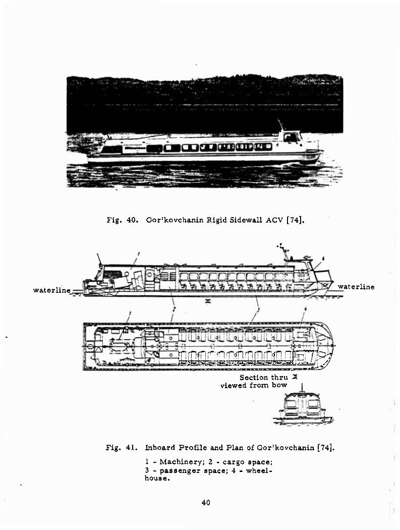
Fig. 40. Gor'kovchanin Rigid Sidewall ACV [74].
waterline waterline
iEffifflOD ESA [HEtDiwrR? Section thru Ä
viewed from bow
^B'
Fig, 41. Inboard Profile and Plan of Gor'kovchanin [74].
1 - Machinery; 2 - cargo space; 3 - passenger space; 4 - wheel- house.
40
■
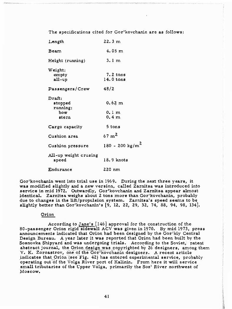
The specifications cited for Gor'kovchanin are as follows:
Length 22.3 m
Beam 4.05 m
Height (running) 3. 1 m
Weight: empty all-up
7. 2 tons 14. 0 tons
Passengers/Crew 48/2
Draft: stopped running:
bow stern
0.62 m
0. 1 m 0.4 m
Cargo capacity 5 tons
Cushion area 67 m2
Cushion pressure
All-up weight crusing speed
Endurance
180 - 200 kg/m
18. 9 knots
220 run
Gor'kovchanin went into trial use in 1969. During the next three years, it was modified slightly and a new version, called Zarnitsa was introduced into service in mid 1972. Outwardly, Gor'kovchanin and Zarnitsa appear almost identical. Zarnitsa weighs about 2 tons more than Gor'kovchanin, probably due to changes in the lift/propulsion system. Zarnitsa's speed seems to be slightly better than Gor'kovchanin's [9, 12, 22, 29, 32, 74, 88, 94, 98, 134].
Orion
According to Jane's [146] approval for the construction of the 80-passenger Orion rigid sidewall ACV was given in 1970. By mid 1973, press announcements indicated that Orion had been designed by the Gor'kiy Central Design Bureau. A year later it was reported that Orion had been built by the Sosnovka Shipyard and was undergoing trials. According to the Soviet, patent abstract journal, the Orion design was copyrighted by 26 designers, among them V. K. Zoroastrov, one of the Gor'kovchanin designers. A recent article indicates that Orion (see Fig. 42) has entered experimental service, probably operating out of the Volga River port of Kalinin. From here it will service small tributaries of the Upper Volga, primarily the Soz' River northwest of Moscow.
41
1
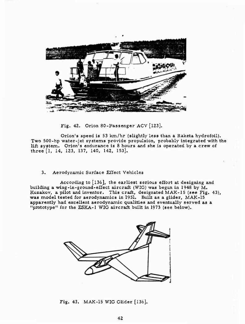
Fig. 42. Orion 80-Passenger ACV [123].
Orion's speed is 53 km/hr (slightly less than a Raketa hydrofoil). Two 500-hp water-jet systems provide propulsion, probably integrated with the lift system. Orion's endurance is 8 hours and she is operated by a crew of three [1, 14, 123, 137, 140, 142, 153].
3. Aerodynamic Surface Effect Vehicles
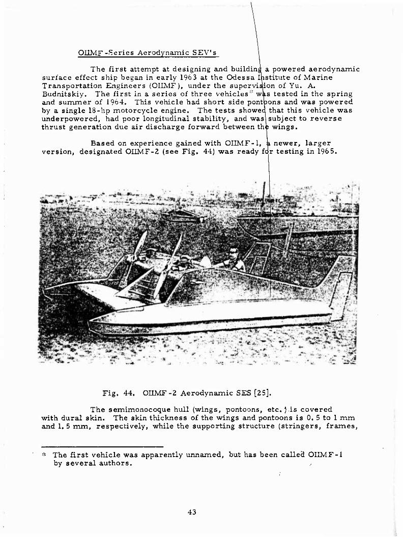
According to [136], the earliest serious effort at designing and building a wing-in-ground-effect aircrait (WIG) was begun in 1948 by M. Kuzakov, a pilot and inventor. This crait, designated MAK-15 (see Fig. 43), was model tested for aerodynamics in 1951. Built as a glider, MAK-15 apparently had excellent aerodynamic qualities and eventually served as a "prototype" for the ESKA-1 WIG aircraft built in 1973 (see below).
Fig. 43. MAK-15 WIG Glider [136].
42
OIIMF--Series Aerodynamic SEV's
The first attempt at designing and building a powered aerodynamic surface effect ship began in early 1963 at the Odessa Institute of Marine Transportation Engineers (OIIMF), under the supervision of Yu. A. Budnitskiy. The first in a series of three vehicles^ was tested in the spring and summer of 1964. This vehicle had short side pontoons and was powered by a single 18-hp motorcycle engine. The tests showed that this vehicle was underpowered, had poor longitudinal stability, and was! subject to reverse thrust generation due air discharge forward between th^ wings.
Based on experience gained with OIIMF-1, k newer, larger version, designated OIIMF-2 (see Fig. 44) was ready far testing in 196 5.
Fig. 44. OIIMF-2 Aerodynamic SES [25].
The semimonocoque hull (wings, pontoons, etc. Vis covered with dural skin. The skin thickness of the wings and pontoons is 0, 5 to 1 mm and 1. 5 mm, respectively, while the supporting structure (stringers, frames.
The first vehicle was apparently unnamed, but has been called OIIMF-1 by several authors.
43
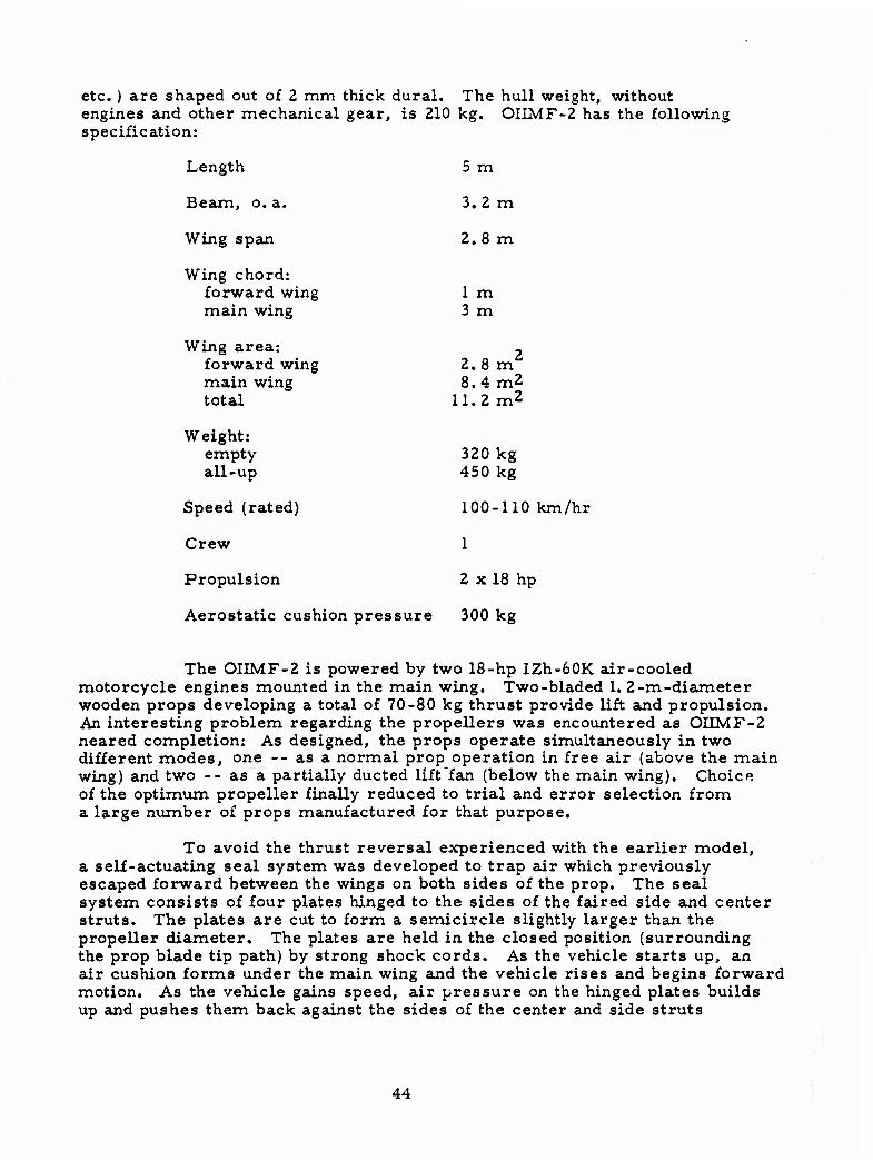
etc. ) are shaped out of 2 mm thick dural. The hull weight, without engines and other mechanical gear, is 210 kg. OIIMF-2 has the following specification:
Length 5 m
Beam, o. a. 3.2 m
Wing span 2.8 m
Wing chord: forward wing main wing
1 m 3 m
Wing area: forward wing main wing total
2.8 m2
8.4m2 11.2 m2
Weight: empty all-up
320 kg 450 kg
Speed (rated) 100-110 km/hr
Crew 1
Propulsion 2 x 18 hp
Aerostatic cushion pressure 300 kg
The OIIMF-2 is powered by two 18-hp IZh-60K air-cooled motorcycle engines mounted in the main wing. Two-bladed 1. 2-m-diameter wooden props developing a total of 70-80 kg thrust provide lift and propulsion. An interesting problem regarding the propellers was encountered as OIIMF-2 neared completion: As designed, the props operate simultaneously in two different modes, one -- as a normal prop operation in free air (above the main wing) and two -- as a partially ducted lift fan (below the main wing). Choice of the optimum propeller finally reduced to trial and error selection from a large number of props manufactured for that purpose.
To avoid the thrust reversal experienced with the earlier model, a self-actuating seal system was developed to trap air which previously escaped forward between the wings on both sides of the prop. The seal system consists of four plates hinged to the sides of the faired side and center struts. The plates are cut to form a semicircle slightly larger than the propeller diameter. The plates are held in the closed position (surrounding the prop blade tip path) by strong shock cords. As the vehicle starts up, an air cushion forms under the main wing and the vehicle rises and begins forward motion. As the vehicle gains speed, air pressure on the hinged plates builds up and pushes them back against the sides of the center and side struts
44
(open position). At the same time the smaller forward wing begins to provi'cle aerodynamic lift along with the main wing. In effect, the vehicle goes through a transition from an aerostatic vehicle to a wing-in-ground- effect vehicle.
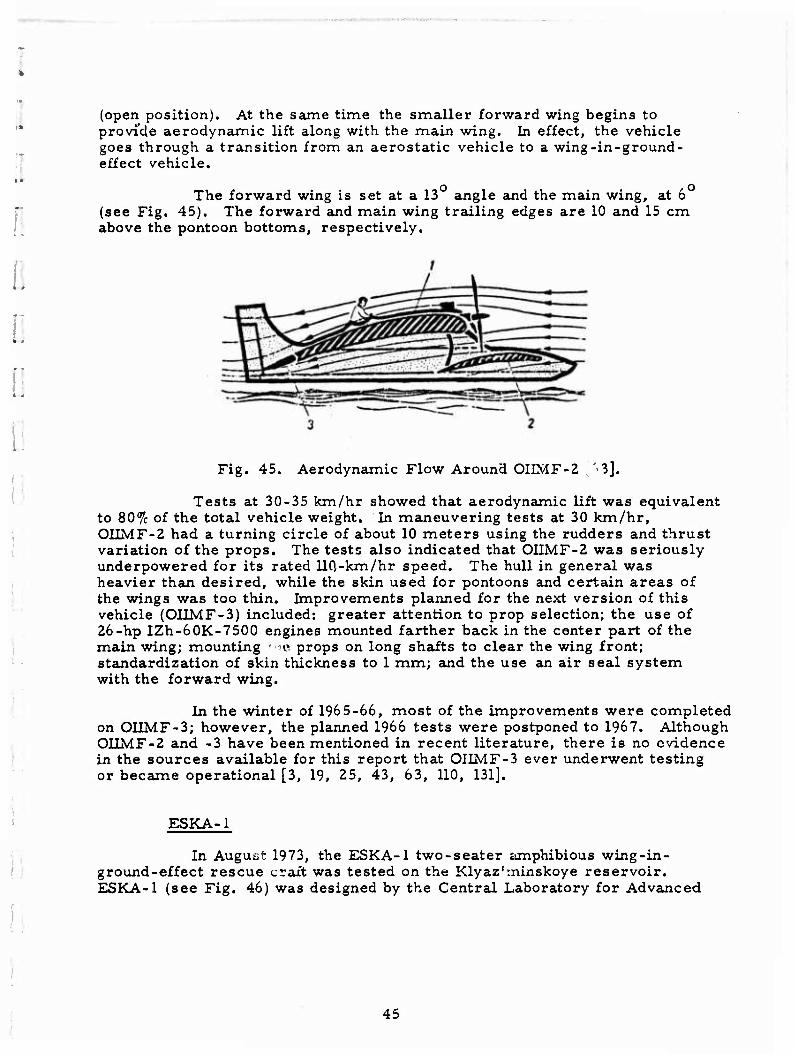
The forward wing is set at a 13 angle and the main wing, at 6 (see Fig. 45). The forward and main wing trailing edges are 10 and 15 cm above the pontoon bottoms, respectively.
Fig. 45. Aerodynamic Flow Around OIIMF-2 '.'I].
Tests at 30-35 km/hr showed that aerodynamic lift was equivalent to 80% of the total vehicle weight. In maneuvering tests at 30 km/hr, OIIMF-2 had a turning circle of about 10 meters using the rudders and thrust variation of the props. The tests also indicated that OIIMF-2 was seriously underpowered for its rated 110,-km/hr speed. The hull in general was heavier than desired, while the skin used for pontoons and certain areas of the wings was too thin. Improvements planned for the next version of this vehicle (OIIMF-3) included: greater attention to prop selection; the use of 26-hp IZh-60K-7500 engines mounted farther back in the center part of the main wing; mounting - c props on long shaits to clear the wing front; standardization of skin thickness to 1 mm; and the use an air seal system with the forward wing.
In the winter of 1965-66, most of the improvements were completed on OIIMF-3; however, the planned 1966 tests were postponed to 1967. Although OIIMF-2 and -3 have been mentioned in recent literature, there is no evidence in the sources available for this report that OIIMF-3 ever underwent testing or became operational [3, 19, 25, 43, 63, 110, 131].
ESKA-1
In August 1973, the ESKA-1 two-seater amphibious wing-in- ground-effect rescue craft was tested on the Klyaz'rninskoye reservoir. ESKA-1 (see Fig. 46) was designed by the Central Laboratory for Advanced
45
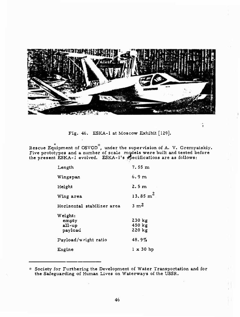
Fig. 46. ESKA-1 at Moscow Exhibit [129].
Rescue Equipment of OSVOD , under the supervision of A. V. Gremyatskiy. Five prototypes and a number of scale models were built and tested before the present ESKA-1 evolved. ESKA-l's specifications are as follows:
Length 7. 55 m
Wingspan 6.9 m
Height 2. 5 m
Wing area 13.85 m2
Horizontal stabilizer area 3 m2
Weight: empty all-up payload
230 kg 450 kg 220 kg
Payload/w. 'ight ratio 48.9%
Engine 1 x 30 hp
* Society for Furthering the Development of Water Transportation and for the Safeguarding of Human Lives on Waterways of the USSR.
46
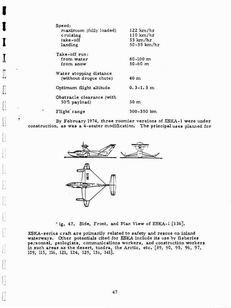
Speed: maximum (fully loaded) cruising take-off landing
Take-off run: from water from snow
Water stopping distance (without drogue chute)
Optimum flight altitude
Obstracle clearance (with 50% payload)
Flight' range
122 km/hr 110 km/hr 55 km/hr 50-55 km/hr
80-100 m 50-60 m
40 m
0. 3-1. 5 m
50 m
300-350 km
By February 1974, three roomier versions of ESKA-1 were under construction, as was a 4-seater modification. The principal uses planned for
lg . 47. Side, Front, and Plan View of ESKA-1 [136].
ESKA-series crait are primarily related to safety and rescue on inland waterways. Other potentials cited for ESKA include its use by fisheries personnel, geologists, communications workers, and construction workers in such areas as the desert, tundra, the Arctic, etc. [89, 90, 95, 96, 97, 109, 115, 116, 121, 124, 129, 136, 141].
47
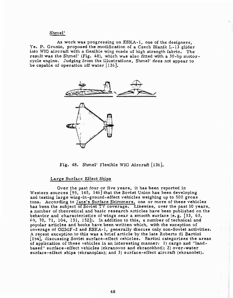
Shmel'
As work was progressing on ESKA-1, one of the designers. Ye. P. Grunin, proposed the modification of a Czech Blanik L-13 glider into WIG aircraft with a flexible wing made of high strength fabric. The result was the Shmel' (Fig. 48), which was also fitted with a 30-hp motor' cycle engine. Judging from the illustrations, Shmel' does not appear to be capable of operation off water [136].
sr\
Fig. 48. Shmel' Flexible WIG Aircraft [136].
Large Surface Effect Ships
Over the past four or five years, it has been reported in Western sources [95, 145, 146] that the Soviet Union has been developing and testing large wing-in-ground-effect vehicles weighing up to 500 gross tons. According to Jane's Surface Skimmers, one or more of these vehicles has been the subject of Soviet TV coverage. Likewise, over the past 10 years, a number of theoretical and basic research articles have been published on the behavior and characteristics of wings near a smooth surface (e.g. [53, 65, 69, 70, 71, 104, 151, 152]). In addition to this, a number of technical and popular articles and books have been written which, with the exception of coverage of OIIMF-2 and ESKA-1, generally discuss only non-Soviet activities. A recent exception to this was a brief article by the late Roberto di Bartini [154], discussing Soviet surface-effect vehicles. Bartini categorizes the areas of application of these vehicles in an interesting manner: 1) cargo and "land- based" surface-effect vehicles (ekranovoz and ekranokhod); 2) over-water surface-effect ships (ekranoplan); and 3) surface-effect aircraft (ekranolet).
48
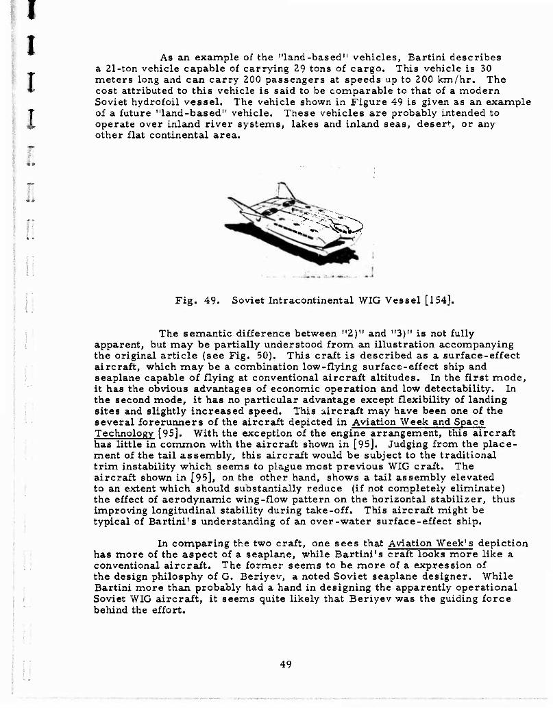
I I As an example of the "land-based" vehicles, Bartini describes
a 21-ton vehicle capable of carrying 29 tons of cargo. This vehicle is 30 f meters long and can carry 200 passengers at speeds up to 200 km/hr. The • cost attributed to this vehicle is said to be comparable to that of a modern
Soviet hydrofoil vessel. The vehicle shown in Figure 49 is given as an example of a future "land-based" vehicle. These vehicles are probably intended to operate over inland river systems, lakes and inland seas, desert, or any other flat continental area.
I
i
-
i. w^sSw»
Fig. 49. Soviet Intracontinental WIG Vessel [154].
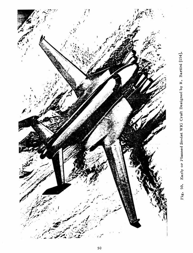
The semantic difference between "2)" and "3)" is not fully apparent, but may be partially understood from an illustration accompanying the original article (see Fig. 50). This craft is described as a surface-effect aircraft, which may be a combination low-flying surface-effect ship and seaplane capable of flying at conventional aircraft altitudes. In the first mode, it has the obvious advantages of economic operation and low detectability. In the second mode, it has no particular advantage except flexibility of landing sites and slightly increased speed. This aircraft may have been one of the several forerunners of the aircraft depicted in Aviation Week and Space Technology f95]. With the exception of the engine arrangement, this aircraft has little in common with the aircraft shown in [95]. Judging from the place- ment of the tail assembly, this aircraft would be subject to the traditional trim instability which seems to plague most previous WIG craft. The aircraft shown in [95], on the other hand, shows a tail assembly elevated to an extent which should substantially reduce (if not completely eliminate) the effect of aerodynamic wing-flow pattern on the horizontal stabilizer, thus improving longitudinal stability during take-off. This aircraft might be typical of Bartini's understanding of an over-water surface-effect ship.
In compaxing the two craft, one sees that Aviation Week's depiction has more of the aspect of a seaplane, while Bartini's craft looks more like a conventional aircraft. The former seems to be more of a expression of the design philosphy of G. Beriyev, a noted Soviet seaplane designer. While Bartini more than probably had a hand in designing the apparently operational Soviet WIG aircraft, it seems quite likely that Beriyev was the guiding force behind the effort.
49
in
S3
tn 0) Q
(4
u Ü
> o
CO
c
0
M
w
o in
50
New light on this aspect of SES development may be shed soon in the form of two books, one of which has just been published5'1 and one to be published in early 1976v',:.
* Kolyzayev, B. A., A. I. Kogorukov, V. A. Litvinenko, and I. L. Popov. Osobennosti proyektirovaniya sudov s novymi printsipami dvizheniya (Specific aspects in the design of vessels based on new propulsion principles). Leningrad, Izd-vo Sudostroyeniye, 1975, 326 p.
*« Treshchevskiy, V. N. , L. D. Volkov, and A. I. Korotkin. Aerodinami- cheskiy eksperiment v sudostroyenii (Aerodynamic experimentation in shipbuilding). [Leningrad], Izd-vo Sudostroyeniye, to be published in 1st quarter of 1976.
51
4. Air Cushion Landing System
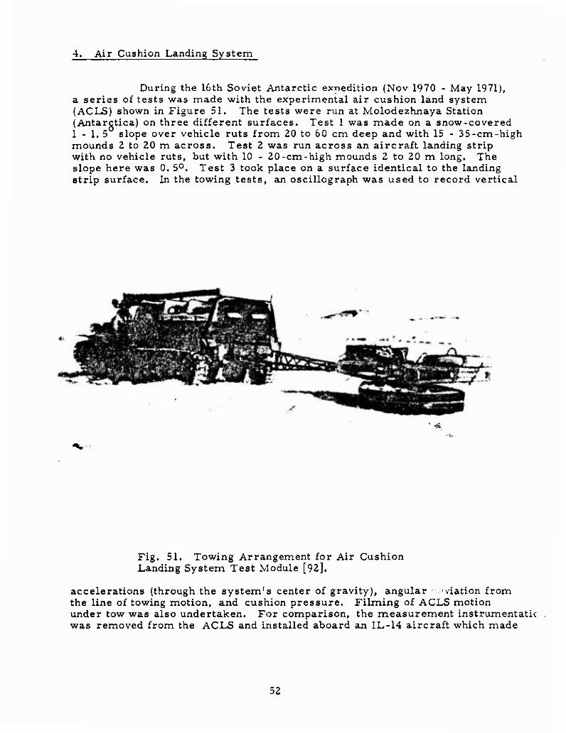
During the 16th Soviet Antarctic expedition (Nov 1970 - May 1971), a series of tests was made with the experimental air cushion land system (ACLS) shown in Figure 51. The tests were run at Molodezhnaya Station (Antarctica) on three different surfaces. Test 1 was made on a snow-covered 1 - 1. 5 slope over vehicle ruts from 20 to 60 cm deep and with 15 - 35-cm-high mounds 2 to 20 m across. Test 2 was run across an aircraft landing strip with no vehicle ruts, but with 10 - 20-cm-high mounds 2 to 20 m long. The slope here was 0. 5°. Test 3 took place on a surface identical to the landing strip surface. In the towing tests, an oscillograph was used to record vertical
Fig. 51. Towing Arrangement for Air Cushion Landing System Test Module [92].
accelerations (through the system's center of gravity), angular -viation from the line of towing motion, and cushion pressure. Filming of ACLS motion under tow was also undertaken. For comparison, the measurement instrumentatic was removed from the ACLS and installed aboard an IL-14 aircraft which made
52
test take-offs and landings on the prepared runway at Molodezhnaya and on natural snow cover on Riiser-Larsen Peninsula. In general, the tests showed that the ACLS had good "roadability" over surfaces which the IL-14 could not even taxi over. Also, there was no incidence of the ACLS skirt freezing to the surface, and even after a long stand the ACLS could break easily away from its resting place. Further work on the development of Arctic-rated ACLS's was recommended, as was the development of air- cushion overland vehicles [92].
1 ■:
10
53
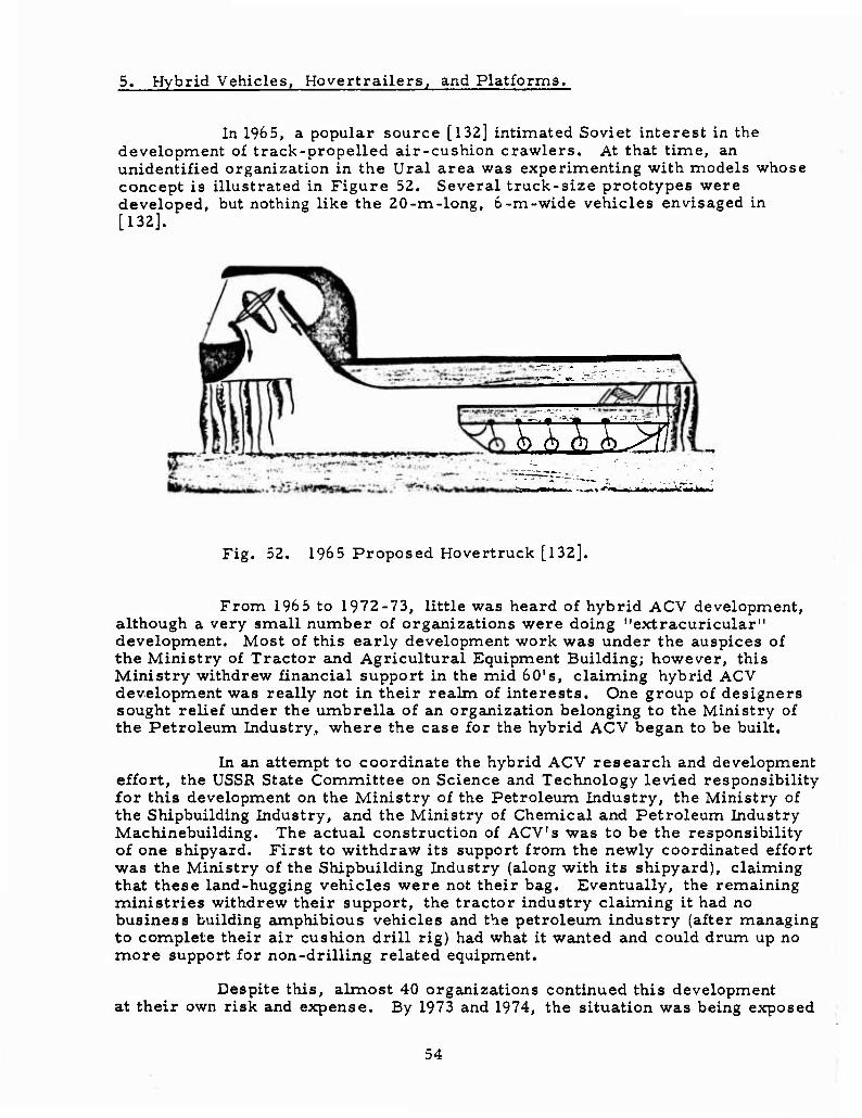
5. Hybrid Vehicles, Hovertrailers, and Platforms.
In 1965, a popular source [132] intimated Soviet interest in the development of track-propelled air-cushion crawlers. At that time, an unidentified organization in the Ural area was experimenting with models whose concept is illustrated in Figure 52. Several truck-size prototypes were developed, but nothing like the 20-m-long, b-m-wide vehicles envisaged in [132].
£ M £B:
Fig. 52. 1965 Proposed Hovertruck [132].
From 196 5 to 1972-73, little was heard of hybrid ACV development, although a very small number of organizations were doing "extracuricular" development. Most of this early development work was under the auspices of the Ministry of Tractor and Agricultural Equipment Building; however, this Ministry withdrew financial support in the mid 60's, claiming hybrid ACV development was really not in their realm of interests. One group of designers sought relief under the umbrella of an organization belonging to the Ministry of the Petroleum Industry, where the case for the hybrid ACV began to be built.
In an attempt to coordinate the hybrid ACV research and development effort, the USSR State Committee on Science and Technology levied responsibility for this development on the Ministry of the Petroleum Industry, the Ministry of the Shipbuilding Industry, and the Ministry of Chemical and Petroleum Industry Machinebuilding. The actual construction of ACV's was to be the responsibility of one shipyard. First to withdraw its support from the newly coordinated effort was the Ministry of the Shipbuilding Industry (along with its shipyard), claiming that these land-hugging vehicles were not their bag. Eventually, the remaining ministries withdrew their support, the tractor industry claiming it had no business building amphibious vehicles and the petroleum industry (after managing to complete their air cushion drill rig) had what it wanted and could drum up no more support for non-drilling related equipment.
Despite this, almost 40 organizations continued this development at their own risk and expense. By 1973 and 1974, the situation was being exposed
54
to open vivisection in Soviet press [51, V- , 114], and no solution was at hand. By this time, vehicles and heavy-duty ho^ertrailers were on order, but the final design and production capabilities did not exist for anything more than sporadic one-of-a-kind production. Despite this dynamic apathy, several developments have taken place and are worthy of note.
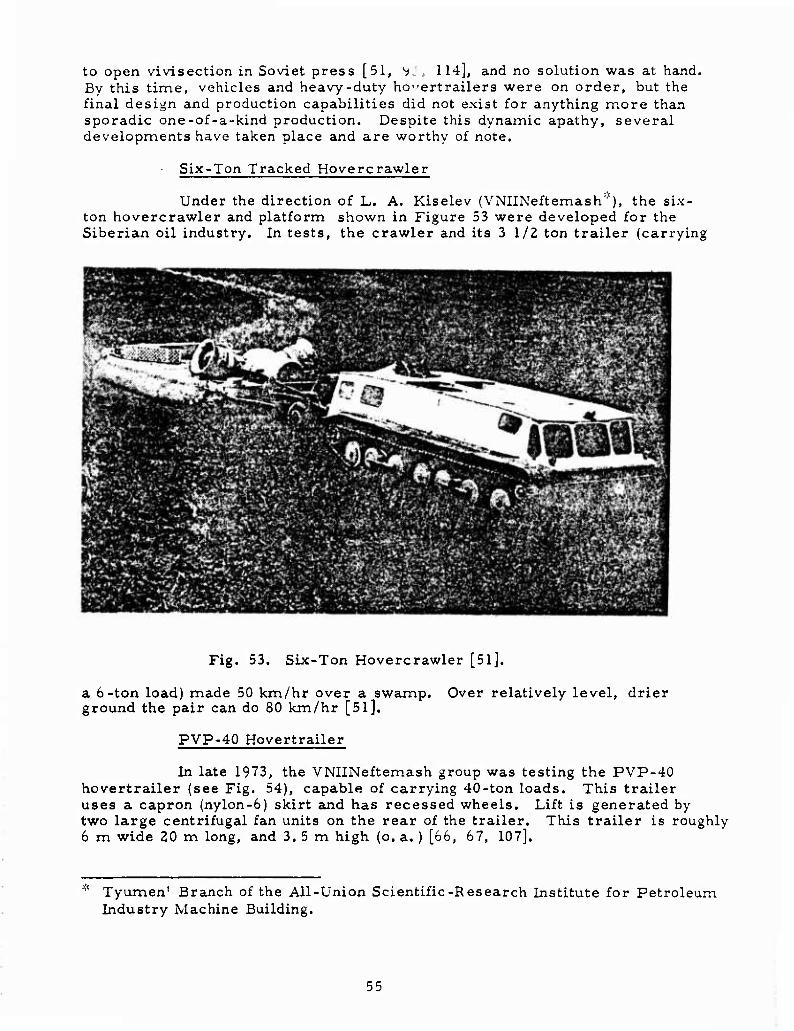
Six-Ton Tracked Hovercrawler
Under the direction of L. A. Kiselev (VNIINeftemash'"), the six- ton hovercrawler and platform shown in Figure 53 were developed for the Siberian oil industry. In tests, the crawler and its 3 1/2 ton trailer (carrying
Fig. 53. Six-Ton Hovercrawler [51].
a 6-ton load) made 50 km/hr over a swamp. Over relatively level, drier ground the pair can do 80 km/hr [5l].
PVP-40 Hovertrailer
In late 1973, the VNIINeftemash group was testing the PVP-40 hovertrailer (see Fig. 54), capable of carrying 40-ton loads. This trailer uses a capron (nylon-6) skirt and has recessed wheels. Lift is generated by two large centrifugal fan units on the rear of the trailer. This trailer is roughly 6 m wide 20 m long, and 3.5 m high (o. a. ) [66, 67, 107],
Tyumen' Branch of the All-union Scientific-Research Institute for Petroleum Industry Machine Building.
55
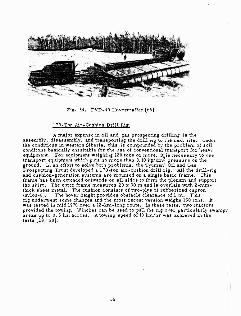
Fig. 54. PVP-40 Hovertrailer [66].
170-Ton Air-Cushion Drill Rig.
A major expense in oil and gas prospecting drilling is the assembly, disassembly, and transporting the drill rig to the next site. Under the conditions in western Siberia, this is compounded by the problem of soil conditons basically unsuitable for the use of conventional transport for heavy equipment. For equipment weighing 120 tons or more, it is necessary to use transport equipment which puts no more than 0.10 kg/cm^ pressure on the ground. Li an effort to solve both problems, the Tyumen' Oil and Gas Prospecting Trust developed a 170-ton air-cushion drill rig. All the drill-rig and cushion-generation systems are mounted on a single basic frame. This frame has been extended outwards on all sides to form the plenum and support the skirt. The outer frame measures 20 x 30 m and is overlain with 2-mm- thick sheet metal. The cushion consists of two-plys of rubberized capron (nylon-6). The hover height provides obstacle clearance of 1 m. This rig underwent some changes and the most recent version weighs 150 tons. It was tested in mid 1970 over a 12-km-long route. In these tests, two tractors provided the towing. Winches can be used to pull the rig over particularly swampy areas up to 0. 5 km across. A towing speed of 10 km/hr was achieved in the tests [28, 60].
56
B. POLAND
Air-cushion vehicle development in Poland began in 19D2 with the construction of a hoverpallet capable of carrying a load of several dozen kilograms. In 1964, a student engineering group in Warsaw tested a one-man hoverscooter weighing 120 kg powered by a 6. 5-hp engine (lift) and a 3. 5-hp engine (propulsion). This hoverscooter was used over water [73, 100],
Over the years, ACV research and experimentation have been conducted by the Aviation Institute, the Ministry of Construction, Gdansk Technical University, the Institute of Turbomachinery, and the Institute of Shipbuilding.
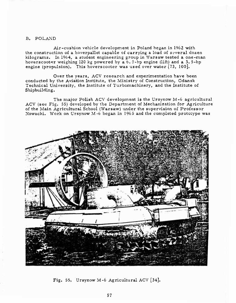
The major Polish ACV development is the Ursynow M-6 agricultural ACV (see Fig. 55) developed by the Department of Mechanization for Agriculture of the Main Agricultural School (Warsaw) under the supervision of Professor Nowacki. Work on Ursynow M-6 began in 196 5 and the completed prototype was
Fig. 55. Ursynow M-6 Agricultural ACV [34].
57
tested in November 1971.
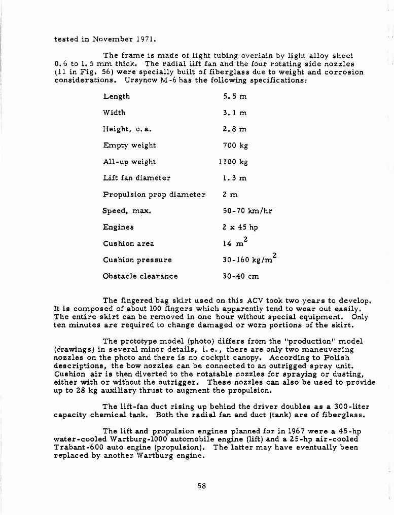
The frame is made of light tubing overlain by light alloy sheet 0. 6 to 1. 5 mm thick. The radial lift fan and the four rotating side nozzles (11 in Fig. 56) were specially built of fiberglass due to weight and corrosion considerations. Ursynow M-6 has the following specifications:
Length 5. 5 m
Width 3. 1 m
Height, o.a. 2.8 m
Empty weight 700 kg
All-up weight 1100 kg
Lift fan diameter 1.3 m
Propulsion prop diaxneter 2 m
Speed, max. 50-70 km/hr
Engines 2 x 45 hp
Cushion area 14 m2
Cushion pressure 30-160 kg/m2
Obstacle clearance 30-40 cm
The fingered bag skirt used on this ACV took two years to develop. It is composed of about 100 fingers which apparently tend to wear out easily. The entire skirt can be removed in one hour without special equipment. Only ten minutes are required to change daumaged or worn portions of the skirt.
The prototype model (photo) differs from the "production" model (drawings) in several minor details, i. e., there are only two maneuvering nozzles on the photo and there is no cockpit canopy. According to Polish descriptions, the bow nozzles can be connected to an outrigged spray unit. Cushion air is then diverted to the rotatable nozzles for spraying or dusting, either with or without the outrigger. These nozzles can also be used to provide up to 28 kg auxiliary thrust to augment the propulsion.
The lift-fan duct rising up behind the driver doubles as a 300-liter capacity chemical tank. Both the radial fan and duct (tank) are of fiberglass.
The lift and propulsion engines planned for in 1967 were a 45-hp water-cooled Wartburg-lOOO automobile engine (lift) and a 25-hp air-cooled Trabant-600 auto engine (propulsion). The latter may have eventually been replaced by another Wartburg engine.
58
VWW/M/WWWW/fo'W/Wt
Fig. 56. Views of Ursynow M-6 (dimensions in mm) [59].
1- Hull; 2- bag skirt; 3- fingers; 4- cockpit; 5- chemical tank; 6- propulsion engine; 7- prop; 8- prop duct; 9- rudder; 10- elevator; 11- maneuvering nozzles; 12- lift fan.
The cost of research, designing, and construction of the prototype Ursynow M-6 was put at about $24, 000 in 1967. It is estimated that in low-lot production, this ACV could be marketed for about $8, 000 (a 1971 figure). There are presently no indications that the Ursynow M-6 has gone into lot production [34, 54, 58, 59, 73, 100, 112].
• 59
C. ROMANIA
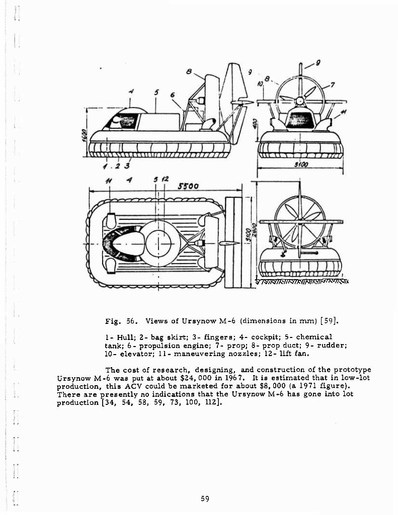
Romanian air-cushion vehicle development began in 1959 under engineers G. Rado and N. N. Patraulea, who built a number of functional scale models. From 1967 to 1972, M. Kiraly and a group of student designers built 2Z such models, and Romania's first operational ACV, designated "023 E" (see Fig. 57). This experiment ACV carries 10 passengers at a maximum speed
Fig. 57. Romanian 023 E Experimental ACV [30].
of 60 km/hr. The propulsion system used on this ACV appears to be a little unusual, and may consist of an amidship propeller thrusting through the box- like ducts at the vehicle's stern. Vertical deflev ors in the duct (or ducts) could be rotated to provide thrust deflection for maneuvering [30].
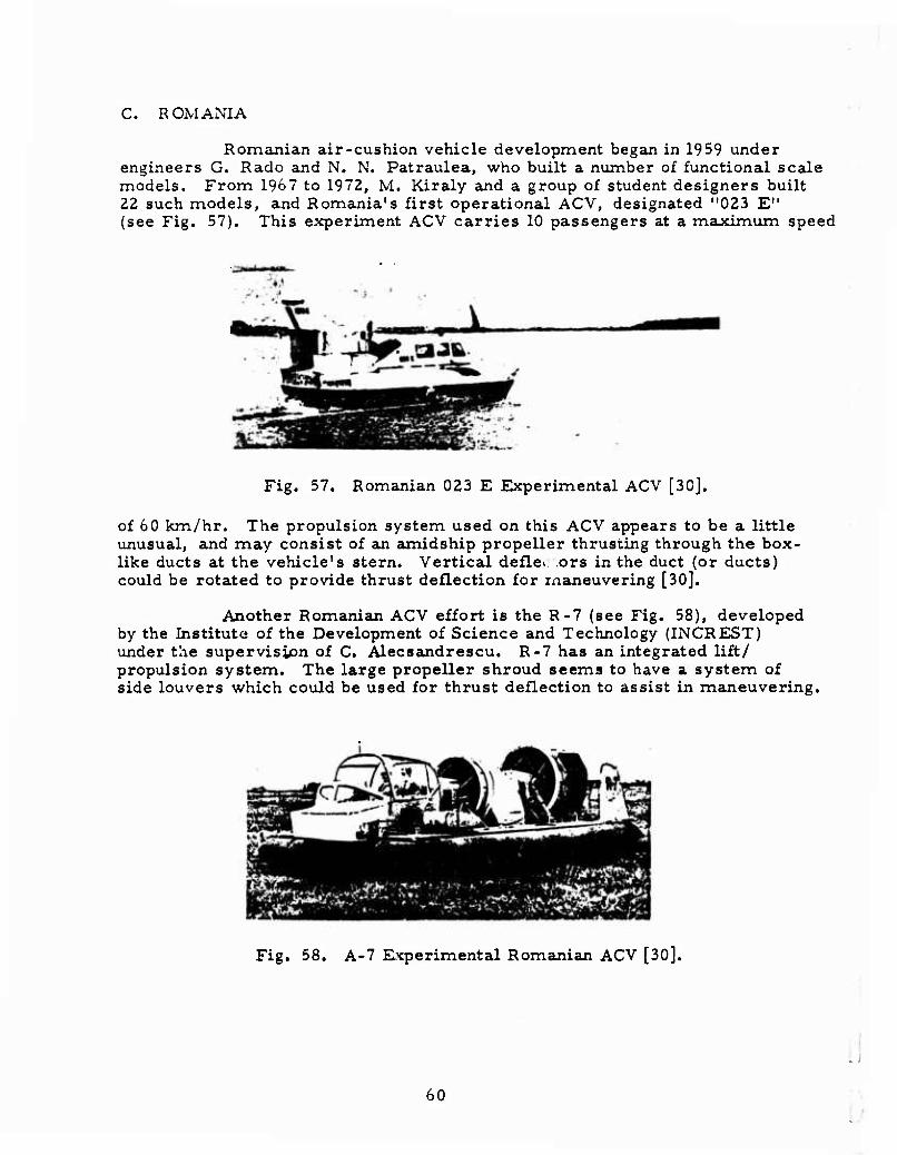
Another Romanian ACV effort is the R-7 (see Fig. 58), developed by the Institute of the Development of Science and Technology (INCREST) under the supervision of C. Alecsandrescu. R-7 has an integrated lift/ propulsion system. The large propeller shroud seems to have a system of side louvers which could be used for thrust deflection to assist in maneuvering.
Fig. 58. A-7 Experimental Romanian ACV [30].
60 ■
■
■
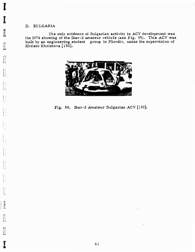
D. BULGARIA
The only evidence ol Bulgarian activity in ACV development was the 1974 showing of the Ikar-2 amateur vehicle (see Fig. 59). This ACV was built by an engineering student group in Plovdiv, under the supervision of Khristo Khristova [150].
Fig. 59. Ikar-2 Amateur Bulgarian ACV [150].
I 61
COMMENTS
During the search for material to be used in compiling this report, it became evident quickly that the major consistent sources of information on SEV development in the Soviet Union were not readily available or being received by U.S. private or government libraries. These institute proceedings generally contain much more detailed information than the semi-technical and popular sources used out of necessity for this report. Another fact noted during the information search was the relatively large number of ACV-related patents which have been granted to Soviet developers.
Simplistically, there are two sides to the Soviet SEV develop- ment coin - the military side and the civilian side. Judging primarily from Western sources, the military side of this development effort is on a scale comparable to that of Great Britian and the Soviet's now have the world's largest operational ACV inventory. Coupled with this is the at-least 10-year- old effort to develop a 500-ton WIG craft, which seems to be almost operational From the standpoint of government funding and resource allocation, themilitary is apparently not having any problem with their SEV development effort. Any problems of a research or engineering nature that may be,plaguing developers just have not squeezed through traditional Soviet reticenc'fe to discuss military R and D matters.
On the civilian side, however, the picture is much different, and the problems seem to vary with the type of vehicle (or application) involved. For example, the development of air-lubricated and rigid sidewall water buses (e. g. Zarya, Zarnitsa, Orion) has proceeded very well, and construction is on a low-lot scale. Air-cushion vehicles such as Sormovich seem to be having a hard time getting "off the ground. " It seems that Sormovich has been "in testing" for at least 10 years and it is hard to believe that her basic hull and frame have survived the extensive modifications that have been performed on her. Several possible replacements for Sormovich have been on the drawing boards since 1967 and 1969, but there is no indication that they are in construction. For the time being, air-cushion vehicle development seems to be stymied, very possibly by preoccupation of shipyards with military ACV development.
Finally, the area which seems to be in the most trouble is the hybrid ACV development area. Here, the problems begin at government ministry levels. Despite efforts to coordinate the development interests of several ministries, the apathetic "let Yuriy do it" attitude prevailed and activity almost ceased. Considering the communication and transport problems facing the Soviet Union east of the Urals, there are compelling reasons for the Soviets to establish an integrated hybrid ACV development program. Canada, which has many of the same geographic problems as the Soviet Union, has a moderate, but stable hybrid R and D program, as well as a commercial production effort. The value and utility of the Canadian effort should be a function of Soviet interest and plans for similar future efforts, if the priority can be forcefully established and ministry-level indifference can be overcome.
62
..
..
'!
c-***««»*-.
:.
;:
:
ö
ö ■
References
1. Chernenko, G. Levkov's vessels. Yunyy tekhnik, no. 7, 1973, 33-35.
n •■ 2. One-man air cushion vehicle:. Militärtechnik, no. 7, 1973, 333.
3. Belavin, N. I. Ekranoplany (Surface effect ships). Leningrad, Izd-vo
Sudostroyeniye, 1968, 174 p.
4. Ruzhitskiy, Ye. I. Vozdushnyye vezdekhody (Surface effect vehicles).
Moskva, Izd-vo Mashinostroyeniye, 1964, 176 p.
5. Kesler, A. A. Rigid sidewall air-cushion vessel. Otkrytiya, izobreteniya,
promyshlennyye obraztsy, tovarnyye znaki, no. 23, 1973, 43 (Author
Certificate 382536)
6. Zhivotovskiy, A. A. , V. R. Shenberg, Yu. A. Lobashov, M. G. Khaymovich,
G. I. Dolgov, A. V. Zaporozhtsev, and G. G. Filipchenko. Air-cushion
vehicle. Otkrytiya, izobreteniya, promyshlennyye obraztsy, tovarnyye
znaki, no. 23, 1973, 213 (Author Certificate 350341).
7. Boguslavskiy, A. N. , and F. L, Markozova. Preliminary estimation of
ACV drag. IN: Leningradskiy Institut vodnogo transporta. Trudy, no. 138,
1972, 72-76. (RZh. Vodnyy transport, no. 11, 1972, Abs. 11A52)
8. Basin, A. M., M. I. Frenkel', V. B. Starobinskiy, A. A. Oskol'skiy,
A. Z. Gorodetskiy, V. I. Migachev, and A. B. Belkin. Planing vessel.
Otkrytiya, izobreteniya, promyshlennyye obraztsy, tovarnyye znaki, no. 9,
1973, 62 (Author Certificate 368107) (RZh. Vodnyy transport, no. 9, 1973,
Abs. 9A290 P).
9. Kesler, A. A. Results of tests of a rigid sidewall ACV. IN: Gor'kovskiy
Institut inzhenerov vodnogo transporta. Trvdy, no. 125, 1972, 25-30 (RZh.
Vodnyy transport, no. 3, 1973, Abs. 3A96).
63
10. Naval review in Leningrad. Sudostroyeniye, no. 10, 1967, insert.
11. Celebration of Soviet Navy Day. Sudostroyeniye, no. 11, 1969, insert
between 60-61.
12. Semenov, D. Without touching the ground. Sovetskaya Rossiya, 12 June
1973, p. 4, col. 8.
13. Zatchayev, A. I., and Ye. G. Finkel'shteyn. Air cushion vehicle.
Otkrytiya, izobreteniya, promyshlennyye obraztsy, tovarnyye znaki, no.
13, 1973, 203 (Author Certificate 329745).
14. Along lae seas and waves. Vechernyaya Moskva, 31 May 1973, p. 2, col. 10.
15. Ronnov, Ye. P. Computation of the mass of the metal hull of a rigid sidewall
cargo ACV. IN: Nauchnaya konferentsiya professial'no-prepodavatel'nogo
sostava Gor'kovskog ;> instituta inzhenerov vodnogo transporta, Materialy.
Gor'kiy, 1972, 138-139. (RZh. Vodnyy transport, no. 5, 1973, Abs. 5A70).
16. Milova, I. I. Pitching equations for a rigid sidewall ACV travelling into the
waves. IN: Nauchno-tekhnicheskaya konferentsiya professial'no-prepodavatel'-
nogo sostava Gor'kovskogo instituta inzhenerov vodnogo transporta, Materialy.
Gor'kiy, 1972, 120-122 (RZh. Vodnyy transport, no. 5, 1973, Abs 5A94).
17. Podkolzin, I. The roadway is the air. Tekhnika molodezhi, no. 1, 1969, 19-21.
18. Pozdnin, B. Experiment on the Volga. Vodnyy transport, 10 April 1973,
p. 4, cols. 6-7.
19. Golov, V. Between the sky and the water. Tekhnika molodezhi, no. 8, 1972,
30-33.
20. Briz-an original ACV. Tekhnika molodezhi, no. 12, 1972, 23.
64
'
I 21. Volkov, Ye. Student exhibits. VDNKh SSSR. no. 12, 3972, 35-36.
1 22. Zarnitsa and her brothers. Vodnyy transport, 10 August 1972, p. 4, col. 1.
c 23. Moskvin, Ye. The ships leave the water. Pravda Ukrainy, 12 September
» 1973, p. 4, cols. 7-8.
l 24. The "Briz" gets going. Vodnyy transport, 1 September 1973, p. 4, col. 8.
25. Belavin, N. I. Surface effect ships. Katera i yakhty, no. 15, 1969, 12-20.
26. Pershin, V, Results of the test operation of the Project R83 vessel. Rechnoy
transport, no. 6, 1972, 54.
27. Volkov, S. P., B. A. Tsarev, and G. T. Chernenko. First Soviet air-cushion
vehicles. Südostroyeniye, no. 7, 1971, 55-56.
:
28. Shibanov, V. V. Drill rig on an air cushion. Neftyanik, no. 2, 1972, 20-21.
29. Andryutin, V. I., G. N. Sirotina, and V. K. Zoroastrov. Experimental air-
cushion vessel. IN: Gor'kovskiy Institut inzhenerov vodnogo transporta. Trudy,
no. 80, 1969, 143-154.
30. Alecsandrescu, C. Application of the Coanda effect leads to Rumanian surface
effect vehicles. Stiinta si tehnica, no. 4, 1973, 10-11.
31. "Flying saucers" in the fields. Nauka i zhizn', no. &, 1972, 87. i
32. Zoroastrov, V. K. Gor'kovchanin rigid sidewall air-cushion vehicle.
Südost royeniye, no. 6, 1969, 74-75.
33. Leningrad technicians develop ACV. Nauka i zhizn', no. 3, 1973, insert 1
between pages 32-33.
65
34. Ursinov M-6. Tekhnika molodezhi, no. 6, 1972, 24-25.
35. Kruglikov, V. F. Ten thousand from fifteen. Tekhnika molodezhi, no. 9,
1972, 2-4.
36. Upwards by propeller. Tekhnika molodezhi, no, 10, 1972, inside front
cover and 40.
37. Mikhaylov, K. I. A flood of discoveries. Tekhnika molodezhi, no. 11,
1972, 2-4.
38. Experimental ACV. NTO SSSR, no. 5, 1972, 38.
39. Soviet shipbuilding exhibit at Expo-67. Sudostroyeniye, no. 4, 1967, 71-72
and insert between 72-73.
40. Pashin, V. M. Economic effectiveness of aerodynamic surface-effect
vessels as related to their dimensions. Sudostroyeniye, no. 5, 1966, 14-17.
41. Belov, I. Navy review in Leningrad [Photo of Soviet Navy ACV].
Sudostroyeniye, no. 2, 1969, insert between 56-57.
42. Pryzgalov, A. A., A. A. Zhivotovskiy, V, R. Shenberg, and S. P. Volkov.
Sormovich air-cushion vessel. Sudostroyeniye, no. 7, 1966, 9-10.
43. Belavin, N. I. Flying ships of the future. Sudostroyeniye, no. 3, 1971, 14-21.
44. Tsaregorodtsev, V. Ye. Invention and engineering development in shipbuilding.
Sudostroyeniye, no. 2, 1970, 59-60.
45. Sormovich ACV tested on the Volga. Tekhnika molodezhi, no. 3, 1966, 9.
,
66
46. Podrez, A. KhAI- Khar'kov Aviation Institute. Tekhnika molodezhi, no.
12, 1967, 19-21.
47. Shcherbakov, V. Youth for engineering. Tekhnika molodezhi, no. 1, 1969,
14-17.
48. The ship runs onto the shore. Tekhnika molodezhi, no. 11, 1970, inside front
cover and 58.
49. Fifty-pass enger ACV tested. Tekhnika molodezhi, no. 3, 1971, 19.
50. Polunov, G. We recognize a bold quest. Tekhnika molodezhi, no. 8, 1968,
12-13.
51. Blokhnin, A. Floating amphibious vehicles. Izvestiya, 31 July 1973, p. 6,
cols. 6-7.
52. Khanzhonkov, V. I. Aerodynamic characteristics of annular jets impinging
on a surface. IN: Moscow. Tsentral'nyy aero-gidrodinamicheskiy Institut.
Promyshlennaya aerodinamika, no. 27, 1966, 145-179.
53. Korolev, V. I, Static stability of craft utilizing the lifting force of aerodynamic
lift surfaces. IN: Nikolayev. Korablestroitel'nyy institut. Sudostroyeniye
i morskiye sooruzheniye, no. 2, 1966, 49-55.
54. Moldenhawer, A. Polish agricultural hovercraft. IN: Warsaw. Instytut
lotnictwa. Biuletyn informacyjny, no. 2(19), 1967, 27-32.
55. Bien, J. Different concept in Polish agricultural hovercraft. IN: Warsaw.
Instytut lotnictwa. Biuletyn informacyjny, no. 6(24), 1967, 27-29.
56. Moldenhawer, A. Present trends in hovercraft design. IN: Warsaw. Instytut
lotnictwa. Biuletyn informacyjny, no. 3, 1965, 34-39.
67
57. Student hovercraft. Skrsydlata Polska no. 22, 30 May 1971, back cover.
58. Ursynow M-6 -- Poland's first agricultural hovercraft. Skrzydlata Polska,
no. 48, 28 November 1971, front cover.
59. Poland's first experimental agricultural hovercraft -- the Ursynow M-6.
Skrzydlata Polska, no. 50, 12 December 1971, 4-6.
60. Muravlenko, V., M. Safiullin, andV. Shibanov. Drill rigs float over
swamps. NTO SSSR, no. 5, 1969, 29.
61. Khrestin, N. Flight of a curious mind. NTO SSSR, no. 7, 1968, 40-41.
62. On an air cushion. NTO SSSR, no. 9, 1967, 57.
63. Pipko, D. Aerodynamic surface effect ships - winged ships of the future.
Nauka i zhizn', no. 1, 1966, page 4 of insert and 33-41.
64. Khanzhonkov, V. I. Aerodinamika apparatov na vozdushnoy podushke
(Aerodynamics of air-cushion vehicles). Moskva, Izd-vo Mashinostroyeniye,
1972, 327 p.
65. Zhilin, Yu. L. Wing with minimum inductive drag near the surface of the
earth. IN: AN SSSR. Izvestiya. Mekhanika i mashinostroyeniye, no. 1,
1964, 148-150.
66. Trailer on air cushion. Pravda, 11 December 1973, p. 6, cols. 3-7.
67. Aleksandrov, B. Forty tons on an air cushion. Izvestiya, 21 November 1973,
p. 3, col. 6.
68. Berestneva, N. S., V. P. Gerasimenko, F. G. Kontsevich, and G. V.
Pavlenko. High-pressure axial fan for air cushion vehicles. Samoletostroyeniye
i tekhnika vozdushnogo flota, no. 28, 1972, 35-39.
68
69. Kholyavko, V.l., and M. A. Fefelov. Nonlinear characteristics of a thin
delta wing near an interface. Samoletostro, eniye i tekhnika vozdushnogo
flota, no. 27, 1972, 3-8.
70. Vachasov, Ye, P., G. F. Kurochka, L. G. Sanzharevskiy, and Yu. F. Usik.
Analysis of the longitudinal disturbed motion of an aerodynamic surface-effect
ship. Samoletostroyeniye i tekhnika vozdushnogo flota, no. 29, 1972, 7-13.
71. Yermolenko, S. D., and V. G. Khrapovitskiy. Calculation of the aerodynamic
characteristics of a system of wings moving at subsonic speed near the
earth or a smooth water surface. Samoletostroyeniye i tekhnika vozdushnogo
flota, no. 32, 1973, 3-15.
72. Letunov, V. S. Suda na vozdushnoy podushke (Air cushion vehicles). Moskva,
Izd-vo Morskoy transport, 1963, 47 p.
73. Moldenhawer, A. Poduszkowce (Air cushion vehicles). Warszawa,
Wydawnictwa Komunikacji i lacznosci, 1966, 260 p.
74. Benua, Yu. Yu., V. K. D'yachenko, B. A. Kolyzayev, V. A. Litvinenko,
I. V. Ozimov, and S. A. Smirnov. Osnovy teorii sudov na vozdushnoy
podushke (Fundamentals of the theory of air-cushion vehicles). Leningrad,
Izd-vo Sudostroyeniye, 1970, 454 p.
75. Bukin, V. F., L. V. Ozimov, M. V. Psarev, and V. F. Ivochkin. Air-cushion
vehicle. Otkrytiya, izobreteniya, promyshlennyye obraztsy, tovarnyye znaki,
no. 4, 1973, 159 (Author Certificate 243421).
76. Klebanov, G. Ya. Interior sealing for a ship hull. Otkrytiya, izobreteniya,
promyshlennyye obraztsy, tova.'nyye znaki, no. 4, 1973, 159 (Author
Certificate 289707).
69
77. Bukin, V. F. , F. A. Gayzer, I. Yvu Oganovskiy, and Yu. F. Ogloblin.
Air-cushion vehicle. Otkrytiya, izobreteniya, promyshlennyye obraztsy,
tovarnyye znaki, no. 4, 1973, 159 (Author Certificate 256535).
78. Zhivotovskiy, A. A., V. R, Shenberg, Yu. A. Lobashev, and V. G.
Savinovskiy. Lift/propuls ion unit for an air-cushion vehicle. Otkrytiya,
izobreteniya, promyshlennyye obraztsy, tovarnyye znaki, no. 10, 1973,
188 (Author Certificate 237606).
79. Zhivotovskiy, A. A., V. R, Shenberg, Yu. A. Lobashev, M. G. Khaymovich,
and V. G. Savinovskiy. Air-cushion vehicle. Otkrytiya, izobreteniya,
promyshlennyye obraztsy, tovarnyye znaki, no. 10, 1973, 187-188 (Author
Certificate 255071).
80. Zhivotovskiy, A. A., V. R, Shenberg, and Yu. A. Lobashev. Air-cashion
vehicle. Otkrytiya, izobreteniya, promyshlennyye obraztsy, tovarnyye
znaki, no. 10, 1973, 188 (Author Certificate 244135).
81. Pyshnov, V. On an air cushion. Aviatsiya i kosmonavtika, no. 2, 1966, 66-71.
82. Kudryavtsev, B. M., M. F. Fiks, Yu. M. Filatov, and D. A. Sorvin. Air
intake device for the fan on air-cushion vehicles. Otkrytiya, izobreteniya,
promyshlennyye obraztsy, tovarnyye znaki, no. 30, 1973, 55 (Author
Certificate 389974).
83. Andryutin, V. I., V. I. Pospelov, and Ye. P. Ronnov. Power unit for an
air-cushion vehicle. Otkrytiya, izobreteniya, promyshlennyye obraztsy,
tovarnyye znaki, no. 29, 1973, 60 (Author Certificate 388936).
84. Gayzer, F. A. , and Yu. F. Ogloblin. Air-cushion vehicle. Otkrytiya,
izobreteniya, promyshlennyye obraztsy, tovarnyye znaki, no. 18, 1973, 176
(Author Certificate 281193).
70
■..-h..J- ,■.,.,, .. ....■, .^ .,,.,,...,.,,■....,-... -,^ . .,.■■■ ,■■..-,).
85. Shperling, M. G. , V. M. Morozov, A. V. Mushanov, B. G. Sirotin, I. V.
Mokhova, N. P. Bukin, Yu. D. Naumov, V. N. Tkach, M. D. Kondratenko,
and G. V. Fedin. Automatic remote-control system for fan-blade pitch.
Otkrytiya, izobreteniya, promyshlennyye obraztsy, tovarnyye znaki, no. 18,
1973, 177 (Author Certificate 317274).
86. Yermolayev, S. G., V. K. D'yachenko, B. G. Freydin, G. D. Baranova,
V. K. Ishchunina, A. N. Bagno, L. B. Sukharev, S. V. Mikhaylyuk, and
Yu. M. Mokhov. Flexible skirt. Otkrytiya, izobreteniya, promyshlennyye
obraztsy, tovarnyye znaki, no. 5, 1973, 176 (Author Certificate 215740).
87. Kholyavko, V. I., K. P. Danil'chenko, V.l. Surus, and V. L. Yeremeyev.
Fan nozzle. Otkrytiya, izobreteniya, promyshlennyye obraztsy, tovarnyye
znaki, no. 31, 1973, 101 (Author Certificate 391292).
88. Matveyev, B. Winged high-speed vessels. Vodnyy transport, 22 January 1973,
p. 4, cols. 1-2.
89. Andreyev, V. At the edge of two elements. Krasnaya zvezda, 17 February
1974, p. 4, col. 1.
90. Barashev, P. Flying over the waves. Pravda, 15 February 1974, p. 6, cols.
4-7.
91. Sherstennikov, L, "Tayfun" is called to the start. Ogonek, no. 6, February
1974, 16 and insert between 16-17.
92. Chapter I. General aspects of the work of the expedition. IN: Leningrad.
Arkticheskiy i antarkticheskiy nauchno-issledovatel'skiy Institut. Sovetskaya
antarkticheskaya ekspeditsiya. Trudy, no. 61, 1973, 7-25.
93. Blokhnin, A. Two "sides" of the air cushion. Tekhnika i nauka, no. 1, 1974,
22-27.
71
94. Zakharov, G. Ships for small rivers. Pravda Ukrainy, 12 February 1974,
p. 4, cols. 5-7.
95. New Soviet hybrid aircraft depicted. Aviation week and space technology,
28 January 1974, 14.
96. Gay, D. Surface effect ship assists rescue teams. Vechernyaya Moskva,
16 March 1974, p. 4, cols. 6-7.
97. Morozova, I. Wings for rescue teams. Yunyy tekhnik, no. 2, 1974, cover
and 26-27.
98. Adasinskiy, S. A. Transportnyye mashiny na vozdushnoy podushke (Air
cushion transport vehicles). Moskva, lzd-vo Nauka, 1964, 105 p.
99. Budnitskiy, Yu. A. Hovering ships. Katera i yakhty, no. 4, 1965, 7-18.
100. Amateur air cushion vehicle. Katera i yakhty, no. 4, 1965, 18.
101. Dobrotvorskiy, A. Flying catamaran. Tekhnika molodezhi, no. 9, 1965.
102. Beriyev, G., and A. Bogatyrev. Flying ocean liners. Nauka i zhizn',
no. 6, 1963, page 3 of insert and 37-42.
103. Zykov, V. D. States of motion of an ACV as a function of its speed and
principal dimensions. IN: Novosibirskiy Institut inzhenerov vodnogo transport.
Trudy, no. 87, 1972, 51-56. (RZh. Vodnyy transport, no. 7, 1973, Abs. 7A74).
104. Rozhdestvenskiy, K. V. Unsteady motion of a low-flying wing of finite
span at the lowest flight altitude limit. IN: Leningradskiy korablestroitel'nyy
Institut. Trudy, no. 80, 1972, 69-76. (RZh Vodnyy transport, no. 7, 1973
Abs. 7A70).
72

I I I I I I T 108. KhAI experimental ACV. Yunyy tekhnik, no. 1, 1969, 5.
105. Yevseyev, A. Zarya over the waves. Tekhnika molodezhi, no. 12, 1969,
19-21.
106. Oskol'skiy, A. A. Zarya air-lubricated passenger vessel. Sudostroyeniye,
no. 8, 1969, 61-63.
107. Gramolin, A. Hovertrailers for the taiga. Komsomol'skaya pravda, 3
April 1974, p. 4, cols. 5-7.
I
:.
..
109. Makarov, Yu, ESKA-1 surface effect ship. Nauka i zhizn', no. 2, 1974,
front cover and 9.
110. Chernyshev, A. The boat floats above the sea. Yunyy tekhnik, no. 9, 1965,
24-26.
111. The ship is small, but valuable. Yunyy tekhnik, no. 2, 1967, 13.
112. Moldenhawer, A. Ursynow M-6 agricultural ACV. Mlody technik, no. 3,
1967, front cover and 44-53.
113. Briz flys along the waves. Izvestiya, 26 August 1973, p. 3 col. 1.
i. 114. Murzin, A., and F. Chursin. An air cushion under the vehicles. Pravda,
28 August 1973, p. 3, cols. 4-8.
115. Wings for rescuers. Sovetskaya Latviya, 25 September 1973, p. 4,
cols. 2-4.
116. Zhuravlev, V. Boldness. Sotsialisticheskaya industriya, 11 October 1973,
i- p. 4, cols. 4-7. M
::
117. Potemkin, L. A. Support for assembling large objects. Otkrytiya,
izobreteniya, promyshlennyye obraztsy, tovarnyye znaki, no. 12, 1973,
52 (Author Certificate 371124).
118. Khanzhonkov, V. I., A. A. Zhivotovskiy, V. R. Shenberg, A. S. Okunev,
V. G. Samunin, A. A. Bryzgalov, S. P. Volkov, and V, V. Moskovkin.
Air cushion vehicle. Opisaniye izobreteniya k avtorskomu svidetel'stva,
no. 240483, 21 March 1969, 2 p.
119. Simakov, Ye. Vozdus'hnyye vezdekhody (Surface effect craft). Moskva,
Izd-vo DOSAAF, 1967, 76 p.
120. Korytov, N. V. Suda i apparaty na vozdushnoy podushke (Air-cushion ships
and vehicles). Moskva, Voyenizdat, 1964, 116 p.
121. Fedotov, S, A launch flies above the ground. Sovetskiy patriot, 2 June 1974,
p. 4, cols. 7-8.
122. Hovering amphibian. Sputnik, no. 5, 1974, 28.
123. Antonov, P. I., et al. Air-cushion vessel. Otkrytiya, izobreteniya,
promyshlennyye obraztsy, tovarnyye znaki, no. 16, 1974, 172 (Product design
certificate no. 3567).
124. Il'in, V. Surface-effect ship is ready for launching. Rabochaya gazeta,
15 June 1974, p. 4, cols. 1-3.
125. Krezelewski, M., E. Brzoska, A. Priss, and P. Krzysztof. Trim
stabilizer for an air cushion vehicle. Polish patent no. 69814, 30 June
1974 (RZh. Vodnyy transport, no. 4, 1975, Abs. 4A47).
126. Boyarinov, V. S. Research or: air-cushion vehicle stability. Gor'kovskiy
Institut inzhenerov vodnogo transporta. Trudy, no. 137, 1974, 12-21. (RZh.
Vodnyy transport, no. 4, 1975, Abs. 4V42)
74
127. Yermolayev, S. G., L. A. Teder, E. A. Aframeyev, B. Ye. Rapoport,
R. G. Kreps, Ya. S. Rabinovich, and V. Ya. Shevelevich. Multihull vessel.
Otkrytiya, izobreteniya, promyshlennyye obraztsy, tovarnyye znaki, no. 2,
1973, 36 (Author Certificate 361920).
128. Zatchayev, A. I., and R. M. Farberova. Air-cushion vehicle. Otkrytiya,
izobreteniya, promyshlennyye obraztsy, tovarnyye znaki, no. 21, 1974, 61
(Author Certificate 431049).
129. Prokof'yev, S. Craftsmanship and research by youth. Krylya rodiny, no.
6, 1974, 6-7.
130. New Soviet air-cushion vehicle. Skryzdlata Polska, no. 3(915), 19 January
1969, back cover.
131. Jaworski, S., and B. A. Cariow. State of the art and prospects for the
development of surface effect ships as a means of maritime transport.
Budownictwo ohretowe, no. 3, 1974, 106-112.
132. Saltykov, I. Air at work. Yunyy tekhnik, no. 12, 1965, 11-13.
133. Andryutin, V,, and V. Pospelov. Economic effectiveness of developing
high-speed passenger vessels with sleeping quarters. Rechnoy transport,
no. 1, 1974, 27-28. (RZh. Vodny>-transport, no. 4, 1974, Abs 4A32).
134. Andryutin, V. I., Ye. P. Ronnov, and V. I. Lyubimov. Feasibilitv study
for the development of a cargo sidewall ACV for small rivers. Gor'kovskiy
Institut inzhenerov vodnogo transporta. Trudy, no. 133, Part I, 1973, 41-48
(RZh. Vodnyy transport, no. 4, 1974, Abs. 4A42).
135. Bogomolov, Yu. N., and A. I. Zatchayev. Anchor unit for an air-cushion
vehicle. Otkrytiya, izobreteniya, promyshlennyye obraztsy, tovarnyye znaki,
no. 48, 1974, 36 (Author Certificate 455035).
75
136. Grunin, Ye. Floating over the water. Tekhnika molodezhi, no. 12, 1974,
30-34.
137. The first "Orion". Vodnyy transport, 26 November 1974, p. 4, col. 1.
138. Chernobryvets, A. P., V. L. Chepurnoy, V. A. Artemenko, Ye. N.
Shpolyanskiy, N. G. Lebed', I. V. Lobov, N. A. Nagornyy, and V. M.
MaTchenko. Inert gas generator. Otkrytiya, izobreteniya, promyshlennyye
obraztsy, tovarnyye znaki, no. 20, 1973, 51. (Author Certificate 379457).
139. D'yachenko, V. K., V. A. Litvinenko, N. V. Proskuryakov, S. A. Smirnov,
and K. I. Solomakhina. Device for controlling ship motion. Otkrytiya,
izobreteniya, promyshlennyye obraztsy tovarnyye znaki, no. 34, 1973, 150
(Author Certificate 394751).
140. Zarya to be replaced. Pravda, 22 September 1974, p. 1, co'.. 8.
141. Barashev, P. Flying over the waves. Sputnik, no. 9, 1974, 38-39.
142. Orion is given the go-ahead. Vodnyy transport, 19 September 1974,
p. 4, col. 1.
143. Sapunova, G. Rainbow over the waves. Leningradskaya pravda, 3 September
1975, p. 4, cols. 2-5.
144. Photo caption: Marines landing from an air cushion vehicle. Sovetskiy voin,
no. 13, 1975, 10-11.
145. Dibbern, J. S. Soviet air cushion vehicles. Canadian aeronautics and space
journal, v. 20, no. 9, November 1974, 439-444.
146. McLeavy, R., ed. Jane's surface skimmers; hovercraft and hydrofoils.
London, Jane's yearbooks, 1972-73; 1973-74.
76
■
)
■
147. Tikhonov, V. I., and A. M. Zakharov. Legkiye gazoturbinnyye dvigateli
bystrokhodnykh sudov (Light gas-turbine engines for high speed ships).
Moskva, Izd-vo Transport, 1973, 135 p.
148. Furlong, R. D. M. Military air cushion vehicles - procurement or
procrastination? International defense review, no. 2, April 1973, 167-175.
149. Klimenko, A. I. Nazemnyy transport budushchego (Ground transportation
of the future). Moskva, Izd-vo Maskovskiy rabochiy, 1975, 118 p.
150. Toshev, T. Friendship helps creativity. Tekhnika molodezhi, no. 5, 1975,
41.
151. Sakhno, A. G., and V. I. Kholyavko. Lift characteristics of low-aspect-
ratio wings with fences. Samoletostroyeniye i tekhnika vozdushnogo flota,
no. 37, 1975, 7-12.
152. Kholyavko, V. I., and Yu. F. Usik. Effect of flow boundaries on the
aerodynamic characteristics of a low-aspect-ratio wing. Samoletostroyeniye
i tekhnika vozdushnogo flota, no. 37, 1975, 12-16.
153. On an air cushion, Sovetskiy soyuz, no. 10, 1975, 31.
154. Shcherbakov, A. TreUisportation of the future; as seen by Soviet designer
Robert di Bartini. Sovetskiy soyuz, no. 11, 1974, 50-51.
77