Embed Size (px)
Citation preview
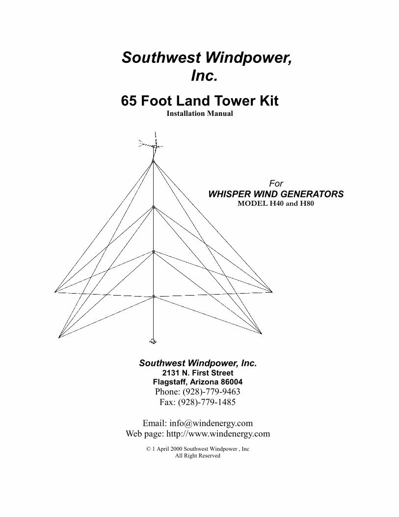
65 Foot Land Tower Kit Installation Manual
Southwest Windpower, Inc.
2131 N. First Street Flagstaff, Arizona 86004 Phone: (928)-779-9463 Fax: (928)-779-1485
Email: [email protected]
Web page: http://www.windenergy.com
© 1 April 2000 Southwest Windpower , Inc All Right Reserved
For WHISPER WIND GENERATORS
MODEL H40 and H80
Southwest Windpower, Inc.
H40/H80 65 Foot Tower Manual Document #0029 REV D
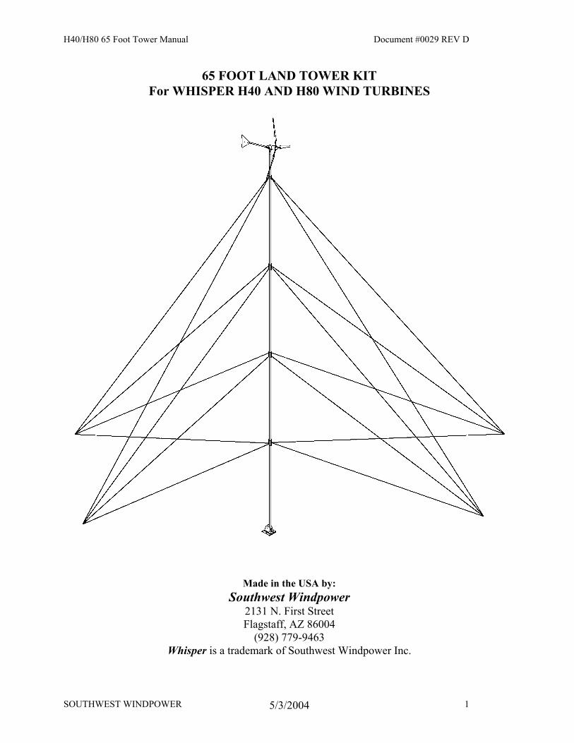
65 FOOT LAND TOWER KIT For WHISPER H40 AND H80 WIND TURBINES
Made in the USA by: Southwest Windpower
2131 N. First Street Flagstaff, AZ 86004
(928) 779-9463 Whisper is a trademark of Southwest Windpower Inc.
SOUTHWEST WINDPOWER 1 5/3/2004
H40/H80 65 Foot Tower Manual Document #0029 REV D
65 FOOT WHISPER LAND TOWER KIT CONGRATULATIONS! You have just received the simplest, most economical 65-foot tower kit available for your Whisper H40 or H80 wind turbine. This kit is designed to be very easy to assemble and erect, however it is important that you read this manual thoroughly before beginning assembly. If you have any questions on proper installation or usage, please call either Southwest Windpower or your dealer for more information. Notice: This information is believed to be accurate, however, Southwest Windpower assumes no responsibility for inaccuracies or omissions. The user of this information and product assumes full responsibility and risk. All specifications are subject to change without notice.
CONTENTS Page Introduction 3 Safety 3 Raising a Tower with a Gin Pole 4 Parts List 6 Tools Needed 7 Step 1: Site Selection 7 Step 2: Tower Pipe Selection 8 Step 3: Tower, Base and Anchor Layout 9 Step 4: Tower Base Assembly 10 Step 5: Guy Wire Anchor Installation 11 Step 6: Assembly of Tower and Turbine 14 Step 7: Attaching Guy Wires To Anchors 16 Step 8: Assembly of Gin Pole 17 Step 9: Raising the Gin Pole 19 Step 10: Raising the Tower 21 Step 11: Final Adjustment of Guy Wires 23 Step 12: Lowering the Tower 23
SOUTHWEST WINDPOWER 2 5/3/2004
H40/H80 65 Foot Tower Manual Document #0029 REV D
Introduction This tower kit is designed specifically for the Southwest Windpower Whisper H40 and H80 wind turbines. To our knowledge this is the most economical and user-friendly tower kit available for the Whisper wind turbines. Four level, guy wire supported construction allows the use of lightweight tubing while providing plenty of strength, even in high wind conditions. With the help of a winch, beast of burden or vehicle, two people can easily erect the tower in a few hours. All that is required is the necessary tubing and the proper anchors for your soil type and a few common tools. At least two people must be present to safely erect the tower. This 65-foot (20 m) tower uses a gin pole to assist in raising the tower. The basic principle of gin pole use is described on the next two pages. This Whisper tower kit includes a galvanized base with separate pivots for both the tower and gin pole. The tower base has a footprint of 16 inches square. In many cases a concrete pad for the tower base is not necessary. Simple extruded aluminum coupling clamps allow the use of different wall thickness of tubing, depending on site requirements. Threaded coupling joints are eliminated, allowing lighter materials to be used with the same or greater strength than a threaded pipe tower. The top guy wire attachment clamps onto the upper mast section. This reduces the number of pieces of tubing used to construct the tower and reduces the stresses concentrated at this point. Pre-cut and swaged guy wires eliminate wire measuring and cutting. Thank you for purchasing our products and for your interest in renewable energy. We are confident that you will enjoy the benefits of your wind powered electrical system for many years to come. If, after reading this manual, you have any further questions please contact your local dealer or Southwest Windpower and we will do our best to assist you.
Safe Installation Safety is the most important consideration to take into account when installing a tower and wind turbine. It is very important to remember that any wind turbine has high speed spinning parts and can be very dangerous if not installed properly! Be sure that the tubing or pipe used for the tower is of adequate strength, that all bolted connections are tightened to the proper torque and that the guy wire anchors are suitable for your conditions, terrain and size of tower. All of these elements are explained in further detail later in this manual. Important! Choose a very calm day to do your installation. A gust of wind at the wrong moment could cause SERIOUS PROBLEMS!
PLEASE…. READ THIS ENTIRE MANUAL BEFORE DOING ANYTHING!
SOUTHWEST WINDPOWER 3 5/3/2004
H40/H80 65 Foot Tower Manual Document #0029 REV D
SOUTHWEST WINDPOWER 4 5/3/2004
H40/H80 65 Foot Tower Manual Document #0029 REV D
SOUTHWEST WINDPOWER 4 5/3/2004
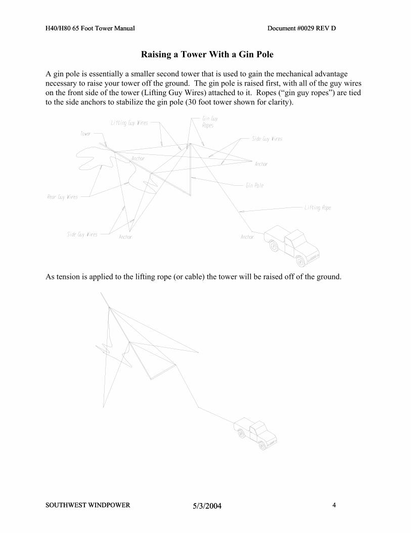
Raising a Tower With a Gin Pole A gin pole is essentially a smaller second tower that is used to gain the mechanical advantage necessary to raise your tower off the ground. The gin pole is raised first, with all of the guy wires on the front side of the tower (Lifting Guy Wires) attached to it. Ropes (“gin guy ropes”) are tied to the side anchors to stabilize the gin pole (30 foot tower shown for clarity).
As tension is applied to the lifting rope (or cable) the tower will be raised off of the ground.
H40/H80 65 Foot Tower Manual Document #0029 REV D
SOUTHWEST WINDPOWER 5 5/3/2004
H40/H80 65 Foot Tower Manual Document #0029 REV D
SOUTHWEST WINDPOWER 5 5/3/2004
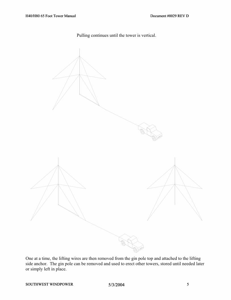
Pulling continues until the tower is vertical.
One at a time, the lifting wires are then removed from the gin pole top and attached to the lifting side anchor. The gin pole can be removed and used to erect other towers, stored until needed later or simply left in place.
H40/H80 65 Foot Tower Manual Document #0029 REV D
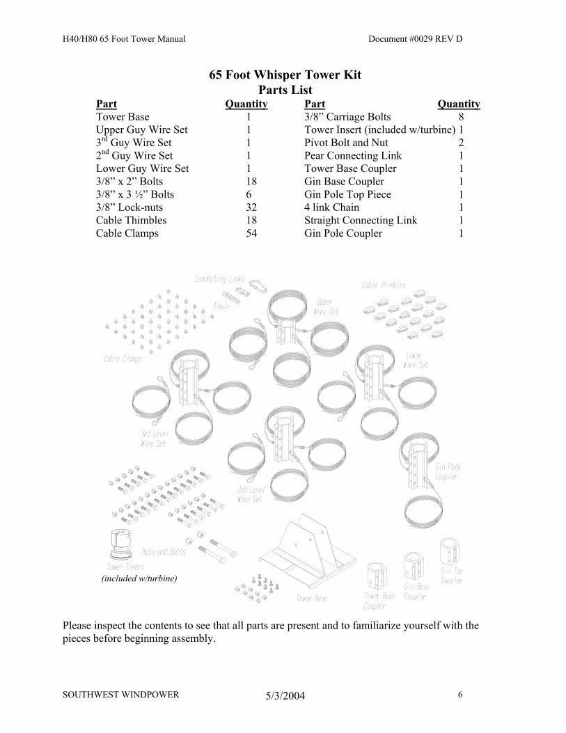
65 Foot Whisper Tower Kit Parts List
Part Quantity Part Quantity Tower Base 1 3/8” Carriage Bolts 8 Upper Guy Wire Set 1 Tower Insert (included w/turbine) 1 3rd Guy Wire Set 1 Pivot Bolt and Nut 2 2nd Guy Wire Set 1 Pear Connecting Link 1 Lower Guy Wire Set 1 Tower Base Coupler 1 3/8” x 2” Bolts 18 Gin Base Coupler 1 3/8” x 3 ½” Bolts 6 Gin Pole Top Piece 1 3/8” Lock-nuts 32 4 link Chain 1 Cable Thimbles 18 Straight Connecting Link 1 Cable Clamps 54 Gin Pole Coupler 1
(included w/turbine)
Please inspect the contents to see that all parts are present and to familiarize yourself with the pieces before beginning assembly.
SOUTHWEST WINDPOWER 6 5/3/2004
H40/H80 65 Foot Tower Manual Document #0029 REV D
Necessary Items Not Included In This Kit: Anchors (explained further in the “Anchors” section of this manual.) Tubing or Pipe for Tower Ground Rod and Clamp Lightning Arrestor* Electrical Wire Wire Connectors (preferably copper split bolts) Pipe Insulation (to prevent wire “rattle” inside pole) * Electrical tape Lifting Cable or Rope (at least 2,000 lb. (950 kg) strength) * Optional items (these are explained in more detail in their relevant assembly sections)
Tools Needed: Round or Half Round File Pliers Carpenters Level (optional) (2) 9/16” or 15mm Wrenches/Sockets Torque Wrench Sledge Hammer 15/16” Wrench Large Adjustable wrench Sawhorse Ladder or 10 foot (3 m) 2x6 or 2x8 3/8” or 10mm Corded or Cordless Drill Motor 3/8” or 10mm Metal Cutting Drill Bit
Step 1: Site Selection
Site selection is the most important factor affecting the performance of your wind turbine! The energy in the wind is the kinetic energy of the moving air mass. What a wind turbine does is convert some of that kinetic energy into rotational energy that can then be converted to electricity. The formula for the amount of power in the wind is a cube function of the wind speed. This means basically that an increase in wind speed of 10% (say from 9 mph to 10 mph) will result in approximately a 37% increase in the power available from the wind and a similar increase in turbine performance. In almost all locations the wind speed increases as you get higher off the ground. This is why a tall tower is very important at most wind sites. As a rule, the turbine should be mounted as high in the air and as far away from obstructions as is possible. To find the best location to erect your tower and wind turbine, study the available area and take note of how the prevailing (most common) winds blow through it. If there are trees, buildings, hills or other obstructions take note of how high they are and where they are in relation to the prevailing wind direction. The best site for your tower and turbine will be upwind and above any obstructions that may exist. If there are houses or trees in the surrounding area a good rule of thumb is to mount the turbine at least 15 feet above any obstructions within 500 feet (150 m) of it. The next consideration in siting your tower and turbine is the distance from the turbine to your batteries. The shortest distance will require the least amount of wire, allow use of the most economical (smallest) wire and reduce the amount of power lost. If a long distance is required between your tower and the batteries it will be necessary to use a heavier gage wire to reduce the resistance of the wire. The power consumed by the wires can be calculated using the formula:
SOUTHWEST WINDPOWER 7 5/3/2004
H40/H80 65 Foot Tower Manual Document #0029 REV D
Power = Current x Current x Resistance
Since the resistance of the wire is directly proportional to its length, making the run shorter will dramatically reduce the amount of power “lost” in the wires. Please refer to the section on “Tower, Base and Anchor Layout”. The amount of space available to assemble and raise the tower may also affect where your tower can be placed.
Step 2: Tower Pipe Selection Because of the high cost of shipping and the widespread availability of the tubing or pipe used for our towers, these materials are not provided by Southwest Windpower. These materials are readily available through most chain link fence suppliers or plumbing companies and will cost much less when purchased locally than if we were to try to ship them from our factory. The “Whisper” land tower kit is designed to use a 2.875 in. (73 mm) outside diameter pipe. This is the same outside diameter as 2 ½ in. steel water pipe where the “2 ½” is a nominal size indicating an outside diameter that is actually 2.875 in. Whether the pipe is “schedule 20”, or “schedule 40”, the outside diameter will be the same and the schedule number determines the wall thickness of the pipe. Use only structural steel for this tower! Never use electrical conduit! The design of this tower kit allows steel pipe (or tubing) of various different wall thickness to be used depending on its availability and on the severity of the wind at your site location. Use the following table to determine the acceptable pipe size(s) for your tower and wind severity. In most locations structural pipe with a wall thickness of .120 inches (3 mm) is sufficient for the conditions and preferable in terms of cost and ease of assembly. We recommend either “CQ-40” or “S-40” fence pipe available from any chain link fence supplier. Electrical conduit or plastic tubing should never be used in your tower assembly, since it is designed to be bent easily, not for strength.
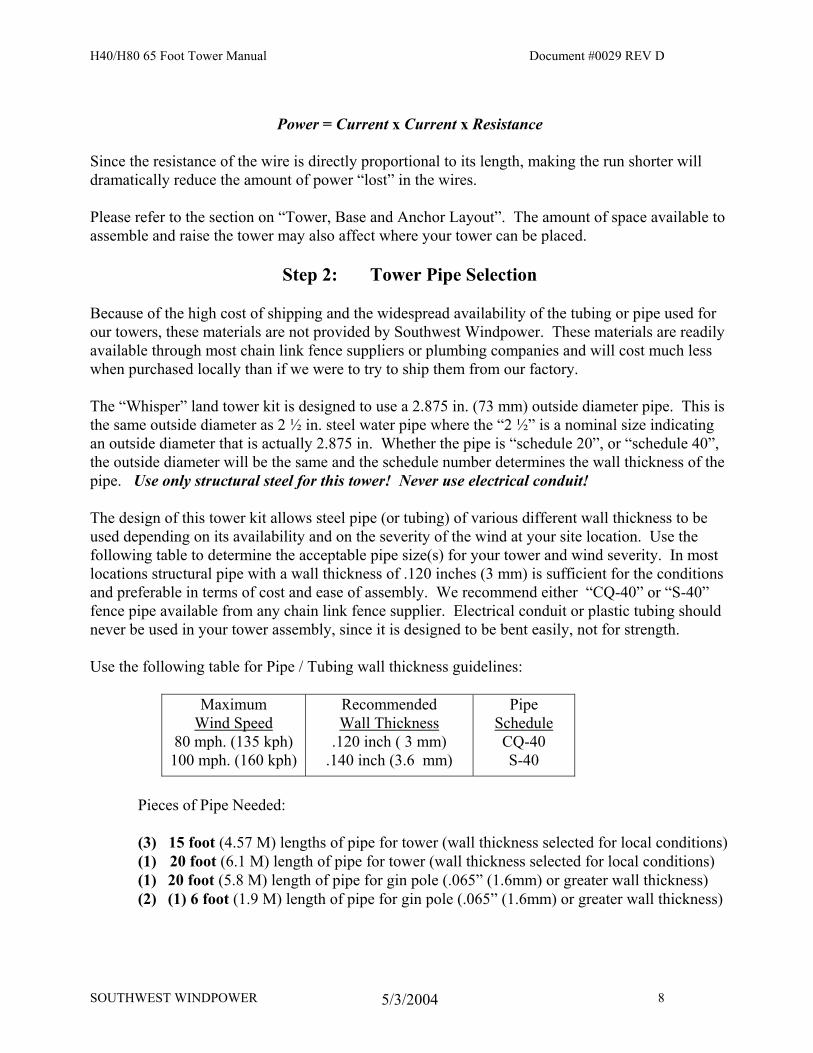
Use the following table for Pipe / Tubing wall thickness guidelines:
Maximum
Wind Speed 80 mph. (135 kph) 100 mph. (160 kph)
Recommended Wall Thickness
.120 inch ( 3 mm) .140 inch (3.6 mm)
Pipe Schedule CQ-40 S-40
Pieces of Pipe Needed:
(3) 15 foot (4.57 M) lengths of pipe for tower (wall thickness selected for local conditions) (1) 20 foot (6.1 M) length of pipe for tower (wall thickness selected for local conditions) (1) 20 foot (5.8 M) length of pipe for gin pole (.065” (1.6mm) or greater wall thickness) (2) (1) 6 foot (1.9 M) length of pipe for gin pole (.065” (1.6mm) or greater wall thickness)
SOUTHWEST WINDPOWER 8 5/3/2004
H40/H80 65 Foot Tower Manual Document #0029 REV D
SOUTHWEST WINDPOWER 9 5/3/2004
H40/H80 65 Foot Tower Manual Document #0029 REV D
SOUTHWEST WINDPOWER 9 5/3/2004
***In some areas there are subsidies and grants available for installing renewable energy systems. If you live in one of these areas and need an engineering analysis for this tower assembly to satisfy your local authorities please contact us. We have an engineering analysis available for this tower kit.
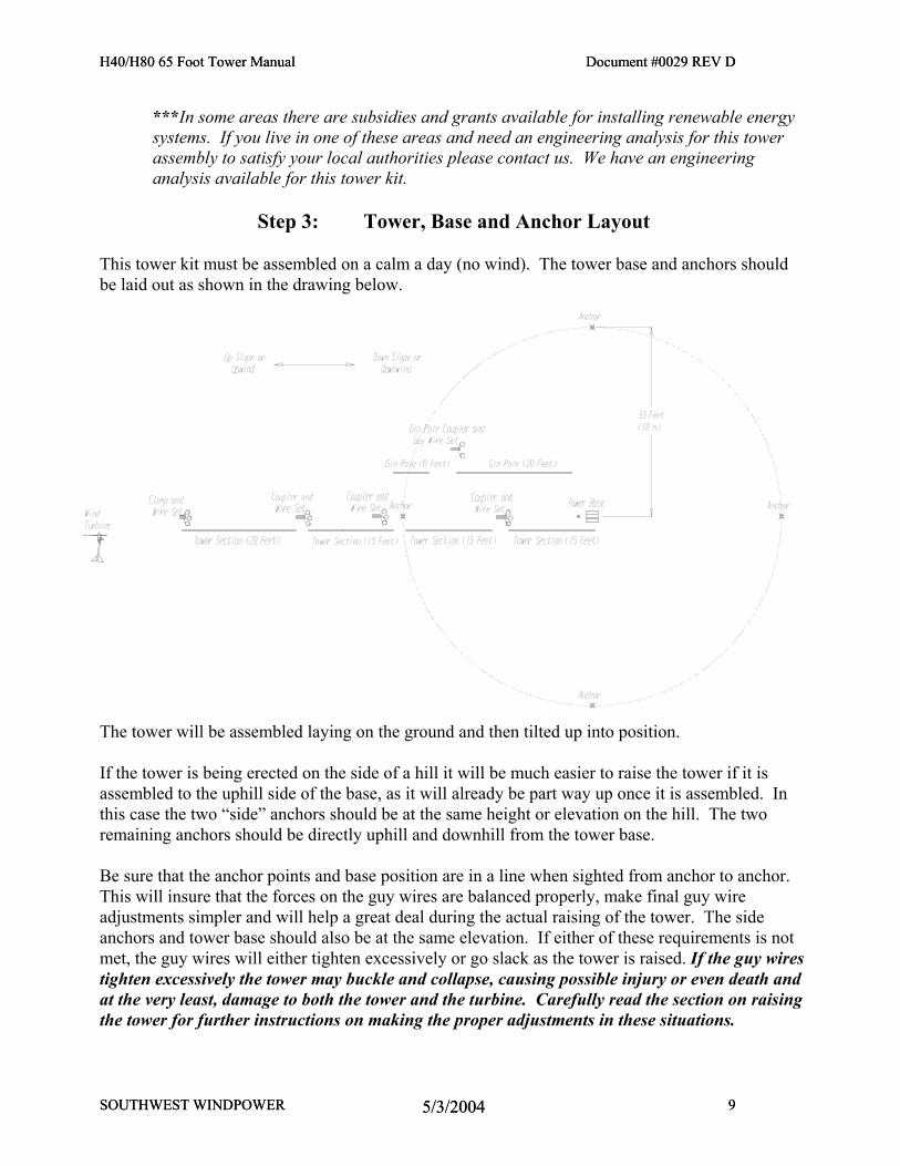
Step 3: Tower, Base and Anchor Layout
This tower kit must be assembled on a calm a day (no wind). The tower base and anchors should be laid out as shown in the drawing below.
The tower will be assembled laying on the ground and then tilted up into position. If the tower is being erected on the side of a hill it will be much easier to raise the tower if it is assembled to the uphill side of the base, as it will already be part way up once it is assembled. In this case the two “side” anchors should be at the same height or elevation on the hill. The two remaining anchors should be directly uphill and downhill from the tower base. Be sure that the anchor points and base position are in a line when sighted from anchor to anchor. This will insure that the forces on the guy wires are balanced properly, make final guy wire adjustments simpler and will help a great deal during the actual raising of the tower. The side anchors and tower base should also be at the same elevation. If either of these requirements is not met, the guy wires will either tighten excessively or go slack as the tower is raised. If the guy wires tighten excessively the tower may buckle and collapse, causing possible injury or even death and at the very least, damage to both the tower and the turbine. Carefully read the section on raising the tower for further instructions on making the proper adjustments in these situations.
H40/H80 65 Foot Tower Manual Document #0029 REV D
SOUTHWEST WINDPOWER 10 5/3/2004
H40/H80 65 Foot Tower Manual Document #0029 REV D
SOUTHWEST WINDPOWER 10 5/3/2004
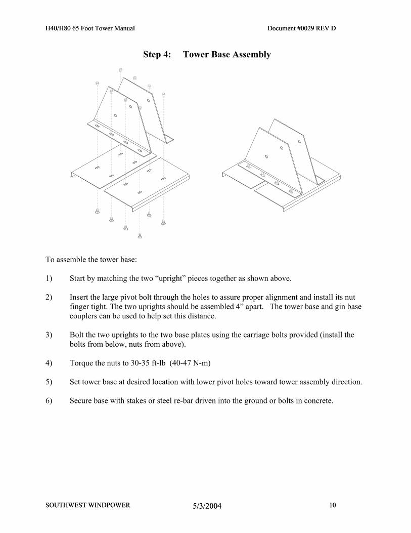
Step 4: Tower Base Assembly
To assemble the tower base: 1) Start by matching the two “upright” pieces together as shown above. 2) Insert the large pivot bolt through the holes to assure proper alignment and install its nut
finger tight. The two uprights should be assembled 4” apart. The tower base and gin base couplers can be used to help set this distance.
3) Bolt the two uprights to the two base plates using the carriage bolts provided (install the
bolts from below, nuts from above). 4) Torque the nuts to 30-35 ft-lb (40-47 N-m) 5) Set tower base at desired location with lower pivot holes toward tower assembly direction. 6) Secure base with stakes or steel re-bar driven into the ground or bolts in concrete.
H40/H80 65 Foot Tower Manual Document #0029 REV D
Step 5: Guy Wire Anchor Installation There are four types of anchors that are most commonly used with our towers; screw in “Auger” type anchors, hammer driven “duckbill” anchors, cast concrete anchors and expansion bolts (for use only in solid rock). What anchor should be used depends on the soil type that the anchors will be placed in. See the following table for our suggestions:
Soil Type Sand or Cinders Loose Gravel Loam Clay Rocky Soil Gravely Soil Solid (Soft) Rock Solid (Hard) Rock
Recommended Anchor Concrete Concrete Auger Duckbill Duckbill Auger or Duckbill Large, Long Expansion Bolt Smaller Expansion Bolt
Alternatives None None Duckbill, Concrete Auger, Concrete Concrete Concrete Large Eye Bolt + Cement None
The loads on a single anchor can approach 1,500 lb. in a 100-mph gale. Make sure that the anchors chosen can withstand at least this much force or the tower will have to be lowered during severe storms. Augers and Duckbill anchors are frequently available at mobile home or landscaping supply stores. Augers are also available from the dealer where your turbine was purchased or from SWWP. Expansion bolts for anchoring in solid rock can be purchased at most hardware stores. Augers: If the soil conditions make their use feasible, augers are the simplest anchors to install. Augers screw into the ground using either a piece of wood, pipe or rod as a “cheater bar”. If a mistake is made or if the tower must be removed an auger can be “unscrewed” out of the ground and reused. They depend on the soil holding together for their strength are not suitable for sand or loose gravel. If the soil is rocky or clay-like you may have difficulty screwing them in. An auger is usually installed by screwing it straight into the ground a few turns to get it started and then tilting it to the desired angle once it is into the ground a few inches. A substantial downward pressure is usually necessary to get an auger started. Screw the augers in as far as possible for the greatest strength. Augers depend on the ability of the soil to hold together for their strength. If augers cannot be screwed in, simply digging a hole and burying them will not work. We often recommend buying augers, and if they cannot be screwed in properly, a hole can be dug and the auger’s disk can then be cast in the concrete. This will provide a good loop for guy wire attachment and make an excellent anchor in the concrete.
SOUTHWEST WINDPOWER 11 5/3/2004
H40/H80 65 Foot Tower Manual Document #0029 REV D
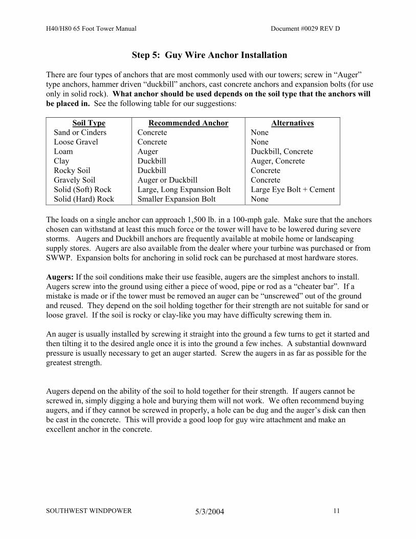
Duckbill Anchors: Duckbill anchors consist of an anchor attached to a cable with a loop on the end. They are driven into the ground using an anchor driver, which is a steel rod with either an enlarged striking surface (for a large hammer) or an attachment for a jackhammer or impact driver. The anchor driver fits into the anchor and holds it straight while it is being driven into the ground. Once the anchor is sufficiently deep in the ground, the driver is withdrawn and the anchor cable is pulled a short distance to “set” the anchor. As the anchor is being set it will rotate perpendicular to the hole made as it was driven in, making it very difficult to move any further.
Please note that once a duckbill anchor is set in place it cannot be removed without digging it out. Buried Concrete: A buried concrete anchor may be the only solution if the ground is loose gravel or sand or if it is too rocky for an auger or duckbill to be driven in. Buried concrete anchors work well in any situation other than solid rock. A hole must be dug in the ground at the desired anchor point. One good tactic is to purchase either augers or duckbills and if they cannot be used as intended, then dig holes and cast them in concrete. Otherwise some other means of attachment must be created for the guy wires, such as a loop of steel reinforcing bar (re-bar) or chain.
SOUTHWEST WINDPOWER 12 5/3/2004
H40/H80 65 Foot Tower Manual Document #0029 REV D
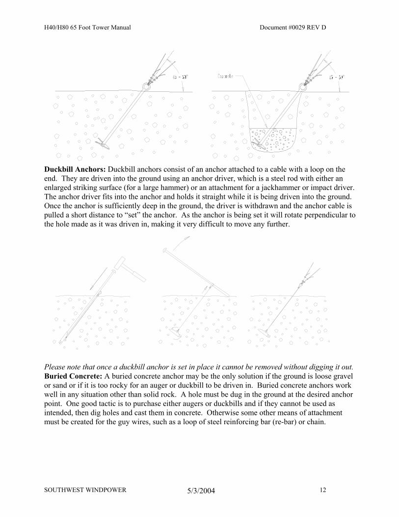
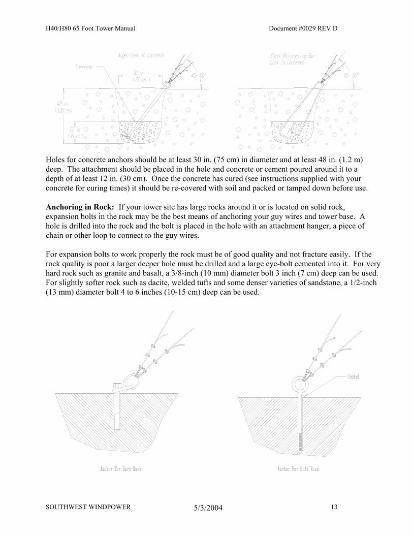
Holes for concrete anchors should be at least 30 in. (75 cm) in diameter and at least 48 in. (1.2 m) deep. The attachment should be placed in the hole and concrete or cement poured around it to a depth of at least 12 in. (30 cm). Once the concrete has cured (see instructions supplied with your concrete for curing times) it should be re-covered with soil and packed or tamped down before use. Anchoring in Rock: If your tower site has large rocks around it or is located on solid rock, expansion bolts in the rock may be the best means of anchoring your guy wires and tower base. A hole is drilled into the rock and the bolt is placed in the hole with an attachment hanger, a piece of chain or other loop to connect to the guy wires. For expansion bolts to work properly the rock must be of good quality and not fracture easily. If the rock quality is poor a larger deeper hole must be drilled and a large eye-bolt cemented into it. For very hard rock such as granite and basalt, a 3/8-inch (10 mm) diameter bolt 3 inch (7 cm) deep can be used. For slightly softer rock such as dacite, welded tufts and some denser varieties of sandstone, a 1/2-inch (13 mm) diameter bolt 4 to 6 inches (10-15 cm) deep can be used.
SOUTHWEST WINDPOWER 13 5/3/2004
H40/H80 65 Foot Tower Manual Document #0029 REV D
SOUTHWEST WINDPOWER 14 5/3/2004
H40/H80 65 Foot Tower Manual Document #0029 REV D
SOUTHWEST WINDPOWER 14 5/3/2004
For softer types of rock, such as sandstone or limestone, a hole 1 inch (25 mm) diameter and 8 inches (20 cm) deep can be drilled and an eye-bolt 5/8 inch (16 mm) in diameter cemented into it. The cement should be mixed just thin enough to pour and poured into the hole before the bolt is installed (a straw inserted to the bottom of the hole before pouring will help prevent a bubble from forming). This will help to insure that the cement goes to the bottom of the hole and help prevent bubbles that may compromise the strength of the attachment. If expansion bolts are to be used, follow the instructions supplied with the bolts. There are several different types of expansion bolts that are installed using different methods.
Step 6: Assembly of Tower and Turbine
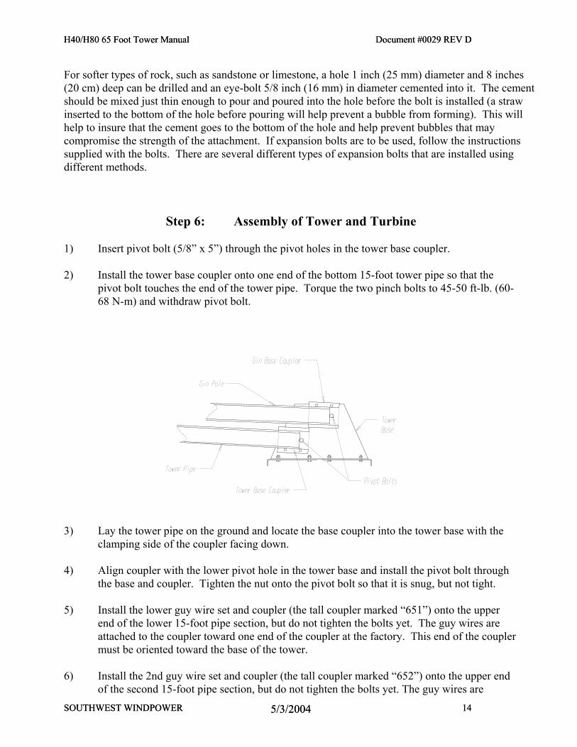
1) Insert pivot bolt (5/8” x 5”) through the pivot holes in the tower base coupler. 2) Install the tower base coupler onto one end of the bottom 15-foot tower pipe so that the
pivot bolt touches the end of the tower pipe. Torque the two pinch bolts to 45-50 ft-lb. (60-68 N-m) and withdraw pivot bolt.
3) Lay the tower pipe on the ground and locate the base coupler into the tower base with the
clamping side of the coupler facing down. 4) Align coupler with the lower pivot hole in the tower base and install the pivot bolt through
the base and coupler. Tighten the nut onto the pivot bolt so that it is snug, but not tight. 5) Install the lower guy wire set and coupler (the tall coupler marked “651”) onto the upper
end of the lower 15-foot pipe section, but do not tighten the bolts yet. The guy wires are attached to the coupler toward one end of the coupler at the factory. This end of the coupler must be oriented toward the base of the tower.
6) Install the 2nd guy wire set and coupler (the tall coupler marked “652”) onto the upper end
of the second 15-foot pipe section, but do not tighten the bolts yet. The guy wires are
H40/H80 65 Foot Tower Manual Document #0029 REV D
attached to the coupler toward one end of the coupler at the factory. This end of the coupler must be oriented toward the base of the tower.
7) Install the 3rd guy wire set and coupler (the tall coupler marked “653”) onto the upper end
of the third 15-foot pipe section, but do not tighten the bolts yet. The guy wires are attached to the coupler toward one end of the coupler at the factory. This end of the coupler must be oriented toward the base of the tower.
8) Install the Upper wire set (the short clamp marked “654”) onto the upper tower pipe. The
center of the clamping piece should be located 5 feet (1.52 m) from tower top. Torque the two bolts to 40-45 ft-lb. (54-60 N-m). Repeat the tightening sequence three times.
9) Prepare the turbines electrical wires by straightening them so they will slide through the
tower pipes more easily and laying them out where they will be fed into the tower pipes. If desired, short pieces of foam insulation made for water pipes can be taped onto the wires at 3-foot (1 m) intervals to reduce wire noise transmitted through the tower itself.
10) Run the turbine wires through the three tower pipes, one pipe section at a time. Taping the
ends of all three wires together makes this easier. 11) Join the lower two pipe sections together, positioning the center of the coupler directly over
the seam between upper and lower pipe sections. Torque the four pinch bolts to 40-45 ft-lb. (54-60 N-m), repeating the tightening sequence at least four times.
12) Join each remaining pipe section to the one below it, working from bottom to top. Torque
the four pinch bolts to 40-45 ft-lb. (54-60 N-m), repeating the tightening sequence at least four times.
13) Raise the turbine end of the upper tower pipe and set it on a saw horse or other supporting
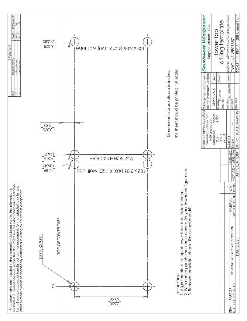
object. The end of the tower should be at least 3-4 feet (1 m) off the ground. Drill holes in tower pipe using supplied template. A tower drilling template is included as the last page of this manual.
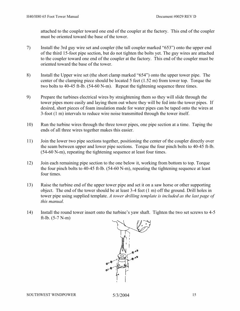
14) Install the round tower insert onto the turbine’s yaw shaft. Tighten the two set screws to 4-5
ft-lb. (5-7 N-m)
SOUTHWEST WINDPOWER 15 5/3/2004
H40/H80 65 Foot Tower Manual Document #0029 REV D
15) Connect the turbine electrical wires to the turbine using split bolts or solder. Insulate well
with electrical tape or heat shrink tubing. 16) Lift the turbine into position and install the tower insert on the turbine into the end of the
tower tube. It will help to have someone pull the slack out of the turbine electrical wires as the turbine is being moved into position.
17) Make sure the bottom of the tower insert is touching the top end of the tower pipe. Insert
and torque all four insert mounting bolts (M8 x 20mm) to 10-11 ft-lb. (12-14 N-m) repeating any tightening sequence used at least four times to insure the lock washer is flattened.
Step 7: Attaching Guy Wires to Anchors
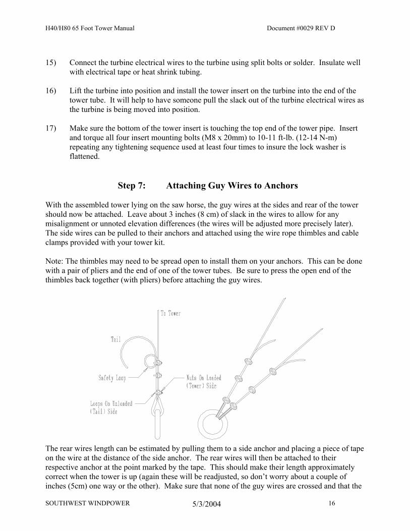
With the assembled tower lying on the saw horse, the guy wires at the sides and rear of the tower should now be attached. Leave about 3 inches (8 cm) of slack in the wires to allow for any misalignment or unnoted elevation differences (the wires will be adjusted more precisely later). The side wires can be pulled to their anchors and attached using the wire rope thimbles and cable clamps provided with your tower kit. Note: The thimbles may need to be spread open to install them on your anchors. This can be done with a pair of pliers and the end of one of the tower tubes. Be sure to press the open end of the thimbles back together (with pliers) before attaching the guy wires.
The rear wires length can be estimated by pulling them to a side anchor and placing a piece of tape on the wire at the distance of the side anchor. The rear wires will then be attached to their respective anchor at the point marked by the tape. This should make their length approximately correct when the tower is up (again these will be readjusted, so don’t worry about a couple of inches (5cm) one way or the other). Make sure that none of the guy wires are crossed and that the
SOUTHWEST WINDPOWER 16 5/3/2004
H40/H80 65 Foot Tower Manual Document #0029 REV D
side wires are straight with no rear wires on top of them. Run the tail end of each guy wire through the second clamp twice, forming a safety loop. Attach all of the side and rear wires securely as shown in the drawing with two clamps on each wire. Use 15-16 ft.-lb. (20-21 N-m) of torque on each nut. It is important (for good strength) that the saddle part of each clamp is on the loaded (tower) side of the guy wire. MAKE SURE THAT ALL GUY WIRES ARE SECURE BEFORE PROCEEDING! At this point the turbine should be propped up on a box, chair, stool or saw horse so that the blades are not damaged when they are installed. Mount the blades and tail onto the turbine at this time.
Step 8: Gin Pole Assembly
The use of a gin pole makes raising your tower much easier than without one. All parts and hardware needed for your gin pole are included in this kit. For the 65 foot tower kit a 20 foot length, and a six foot (1 m) length of 2 ½” pipe (2.875” (73mm) actual outside diameter) are needed for the gin pole. The gin pole will be assembled lying on top of the tower pipe itself. It uses the upper set of pivot holes in the tower base. Assembly is as follows: 1) Insert pivot bolt (5/8” x 5”) through the pivot holes in the gin base coupler. 2) Install the gin base coupler onto the bottom of the 20-foot long gin pole section so that the
pivot bolt touches the end of the pole. Torque the two pinch bolts to 45-50 ft-lb. (60-68 N-m) and withdraw pivot bolt.
3) Lay the gin pole on top of the tower pipe and locate the coupler into the tower base with the clamping side of the coupler facing up.
4) Align coupler with the upper pivot hole in the tower base and install the pivot bolt through
the base and coupler. Tighten the nut onto the pivot bolt so that it is snug, but not tight, against the tower base.
5) Slide the gin pole coupler onto the upper end of the 20-foot section and move the six-foot
section into position. 6) Join the two sections together, positioning the center of the coupler directly over the seam
between upper and lower pipe sections. Torque the four pinch bolts to 40-45 ft-lb. (54-60 N-m), repeating the tightening sequence at least four times.
7) Attach the gin pole guy wires to the side anchors. There should be no slack, but only slight
tension in these wires.
SOUTHWEST WINDPOWER 17 5/3/2004
H40/H80 65 Foot Tower Manual Document #0029 REV D
SOUTHWEST WINDPOWER 18 5/3/2004
H40/H80 65 Foot Tower Manual Document #0029 REV D
SOUTHWEST WINDPOWER 18 5/3/2004
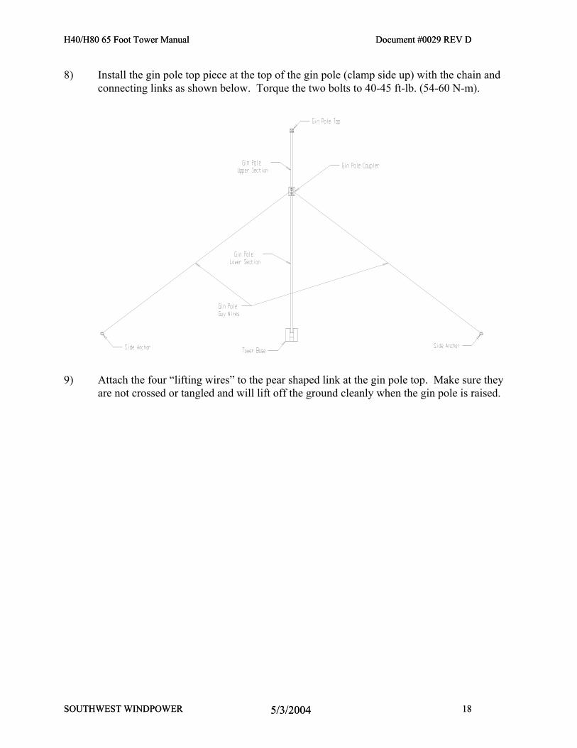
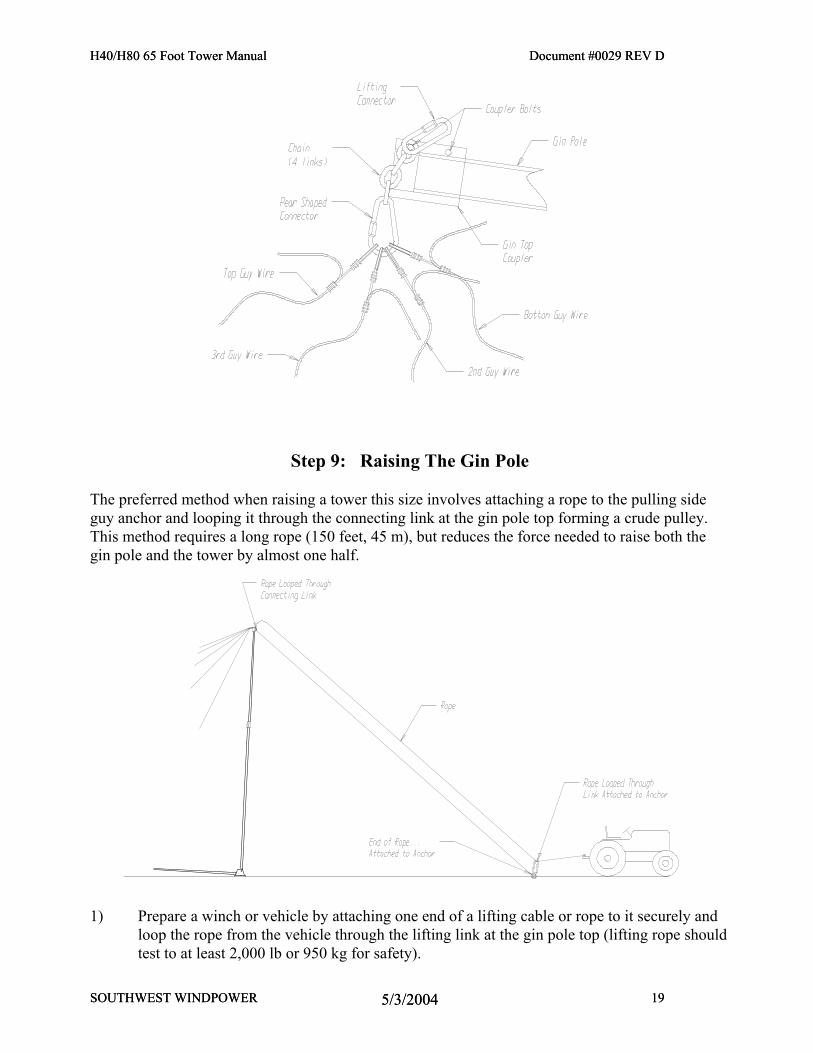
8) Install the gin pole top piece at the top of the gin pole (clamp side up) with the chain and connecting links as shown below. Torque the two bolts to 40-45 ft-lb. (54-60 N-m).
9) Attach the four “lifting wires” to the pear shaped link at the gin pole top. Make sure they
are not crossed or tangled and will lift off the ground cleanly when the gin pole is raised.
H40/H80 65 Foot Tower Manual Document #0029 REV D
SOUTHWEST WINDPOWER 19 5/3/2004
H40/H80 65 Foot Tower Manual Document #0029 REV D
SOUTHWEST WINDPOWER 19 5/3/2004
Step 9: Raising The Gin Pole
The preferred method when raising a tower this size involves attaching a rope to the pulling side guy anchor and looping it through the connecting link at the gin pole top forming a crude pulley. This method requires a long rope (150 feet, 45 m), but reduces the force needed to raise both the gin pole and the tower by almost one half.
1) Prepare a winch or vehicle by attaching one end of a lifting cable or rope to it securely and
loop the rope from the vehicle through the lifting link at the gin pole top (lifting rope should test to at least 2,000 lb or 950 kg for safety).
H40/H80 65 Foot Tower Manual Document #0029 REV D
SOUTHWEST WINDPOWER 20 5/3/2004
H40/H80 65 Foot Tower Manual Document #0029 REV D
SOUTHWEST WINDPOWER 20 5/3/2004
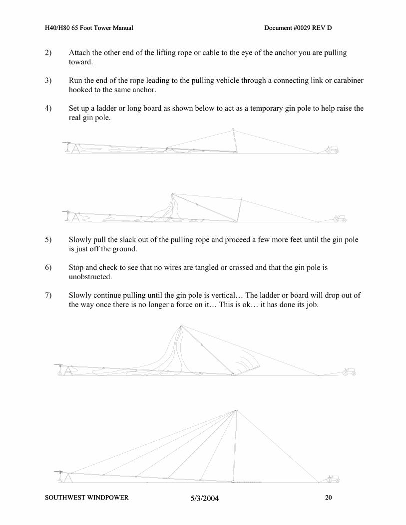
2) Attach the other end of the lifting rope or cable to the eye of the anchor you are pulling toward.
3) Run the end of the rope leading to the pulling vehicle through a connecting link or carabiner hooked to the same anchor.
4) Set up a ladder or long board as shown below to act as a temporary gin pole to help raise the real gin pole.
5) Slowly pull the slack out of the pulling rope and proceed a few more feet until the gin pole
is just off the ground. 6) Stop and check to see that no wires are tangled or crossed and that the gin pole is
unobstructed. 7) Slowly continue pulling until the gin pole is vertical… The ladder or board will drop out of
the way once there is no longer a force on it… This is ok… it has done its job.
H40/H80 65 Foot Tower Manual Document #0029 REV D
SOUTHWEST WINDPOWER 21 5/3/2004
H40/H80 65 Foot Tower Manual Document #0029 REV D
SOUTHWEST WINDPOWER 21 5/3/2004
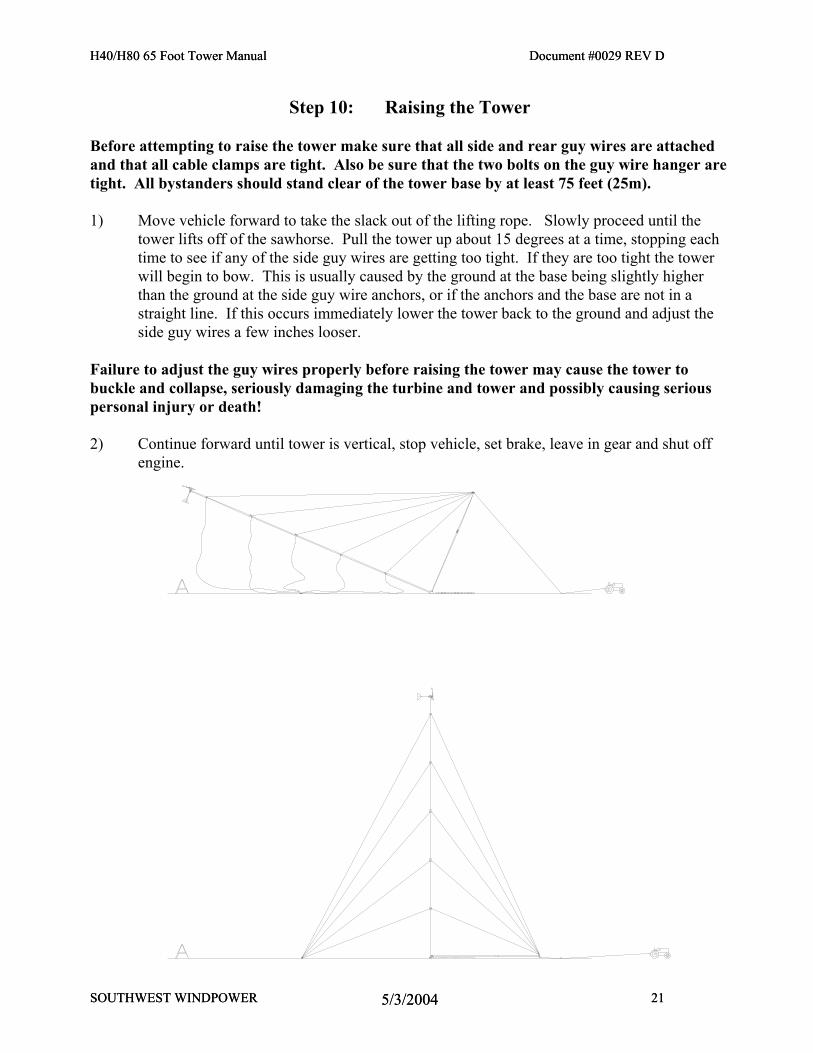
Step 10: Raising the Tower Before attempting to raise the tower make sure that all side and rear guy wires are attached and that all cable clamps are tight. Also be sure that the two bolts on the guy wire hanger are tight. All bystanders should stand clear of the tower base by at least 75 feet (25m). 1) Move vehicle forward to take the slack out of the lifting rope. Slowly proceed until the
tower lifts off of the sawhorse. Pull the tower up about 15 degrees at a time, stopping each time to see if any of the side guy wires are getting too tight. If they are too tight the tower will begin to bow. This is usually caused by the ground at the base being slightly higher than the ground at the side guy wire anchors, or if the anchors and the base are not in a straight line. If this occurs immediately lower the tower back to the ground and adjust the side guy wires a few inches looser.
Failure to adjust the guy wires properly before raising the tower may cause the tower to buckle and collapse, seriously damaging the turbine and tower and possibly causing serious personal injury or death! 2) Continue forward until tower is vertical, stop vehicle, set brake, leave in gear and shut off
engine.
H40/H80 65 Foot Tower Manual Document #0029 REV D
SOUTHWEST WINDPOWER 22 5/3/2004
H40/H80 65 Foot Tower Manual Document #0029 REV D
SOUTHWEST WINDPOWER 22 5/3/2004
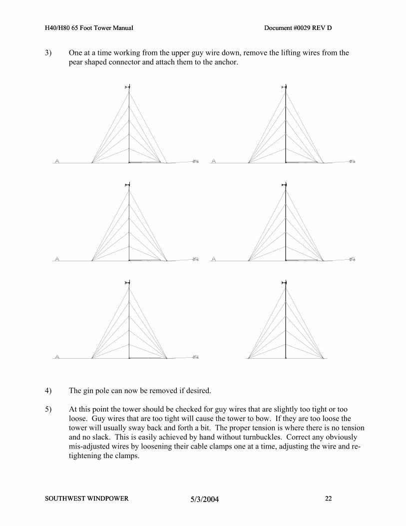
3) One at a time working from the upper guy wire down, remove the lifting wires from the pear shaped connector and attach them to the anchor.
4) The gin pole can now be removed if desired. 5) At this point the tower should be checked for guy wires that are slightly too tight or too
loose. Guy wires that are too tight will cause the tower to bow. If they are too loose the tower will usually sway back and forth a bit. The proper tension is where there is no tension and no slack. This is easily achieved by hand without turnbuckles. Correct any obviously mis-adjusted wires by loosening their cable clamps one at a time, adjusting the wire and re-tightening the clamps.
H40/H80 65 Foot Tower Manual Document #0029 REV D
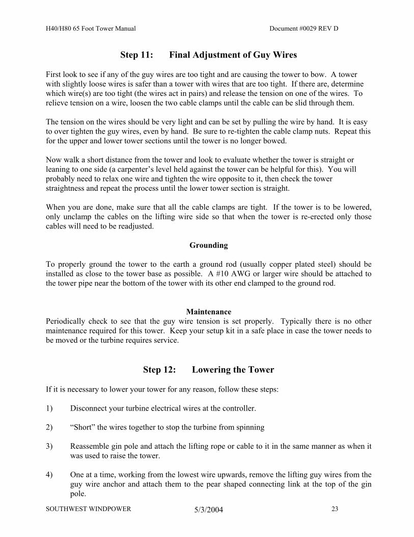
Step 11: Final Adjustment of Guy Wires First look to see if any of the guy wires are too tight and are causing the tower to bow. A tower with slightly loose wires is safer than a tower with wires that are too tight. If there are, determine which wire(s) are too tight (the wires act in pairs) and release the tension on one of the wires. To relieve tension on a wire, loosen the two cable clamps until the cable can be slid through them. The tension on the wires should be very light and can be set by pulling the wire by hand. It is easy to over tighten the guy wires, even by hand. Be sure to re-tighten the cable clamp nuts. Repeat this for the upper and lower tower sections until the tower is no longer bowed. Now walk a short distance from the tower and look to evaluate whether the tower is straight or leaning to one side (a carpenter’s level held against the tower can be helpful for this). You will probably need to relax one wire and tighten the wire opposite to it, then check the tower straightness and repeat the process until the lower tower section is straight. When you are done, make sure that all the cable clamps are tight. If the tower is to be lowered, only unclamp the cables on the lifting wire side so that when the tower is re-erected only those cables will need to be readjusted.
Grounding To properly ground the tower to the earth a ground rod (usually copper plated steel) should be installed as close to the tower base as possible. A #10 AWG or larger wire should be attached to the tower pipe near the bottom of the tower with its other end clamped to the ground rod.
Maintenance Periodically check to see that the guy wire tension is set properly. Typically there is no other maintenance required for this tower. Keep your setup kit in a safe place in case the tower needs to be moved or the turbine requires service.
Step 12: Lowering the Tower If it is necessary to lower your tower for any reason, follow these steps: 1) Disconnect your turbine electrical wires at the controller. 2) “Short” the wires together to stop the turbine from spinning 3) Reassemble gin pole and attach the lifting rope or cable to it in the same manner as when it
was used to raise the tower. 4) One at a time, working from the lowest wire upwards, remove the lifting guy wires from the
guy wire anchor and attach them to the pear shaped connecting link at the top of the gin pole.
SOUTHWEST WINDPOWER 23 5/3/2004

H40/H80 65 Foot Tower Manual Document #0029 REV D
5) Position a sawhorse where the tower is expected to come to the ground to protect the turbine
blades from damage. 6) Tip the tower by hand until the lifting wires and main lifting cable or rope are taut and
supporting the tower. 7) Slowly lower the tower until it is resting on the saw horse.
SOUTHWEST WINDPOWER 24 5/3/2004
APP
ROV
EDD
ATE
DES
CRI
PTIO
NRE
V.
REV
ISIO
NS
Pro
prie
tary
righ
ts a
re in
clud
ed in
the
info
rmat
ion
disc
lose
d h
erei
n. T
his i
nfor
mat
ion
issu
bmitt
ed in
con
fiden
ce a
nd n
eith
er th
e d
ocum
ent n
or th
e in
form
atio
n d
isclo
sed
her
e-in
shal
l be
repr
oduc
ed o
r tra
nsfe
rred
to o
ther
doc
umen
ts fo
r man
ufac
turin
g or
for a
nyot
her p
urpo
se e
xcep
t as s
peci
fical
ly a
utho
rized
in w
ritin
g by
Sou
thw
est W
ind
pow
er.
NEX
T A
SSY
USED
ON
APP
LIC
ATIO
ND
O N
OT
SCA
LE D
RAW
ING
---
FIN
ISH
MA
TERI
AL
Unle
ss o
ther
wise
spec
ified
dim
ensio
ns a
re in
mm
.to
lera
nces
are
:d
istan
ces
ang
les
X. ±
1
±
30
'.X
± .5
.X
X ±
.1
QUA
L EN
G
MFG
EN
G
RESP
EN
G
CHE
CKE
D
DRA
WN
APP
ROV
ALS
DA
TE
REV
. Ash
eet 1
of 1
DW
G. N
°C
AD
FIL
E:
SIZE
ASC
ALE
1 :
1
CA
D-g
ener
ated
dra
win
gd
o no
t man
ually
upd
ate
NC
initi
al re
leas
ese
p 0
DA
J
Flag
staf
f, A
rizon
a U
.S.A
.
25 se
p 0
H40-
H80
WP0
1387
D. J
ones
WP0
1387
A to
wer
top
dril
ling
tem
plat
e
tow
er to
pd
rillin
g te
mpl
ate
PART
S LI
ST
--
--
ITEM
NO
.
PA
RT O
RID
ENTIF
YIN
G N
°N
OM
ENC
LATU
RE O
R D
ESC
RIPT
ION
M
ATE
RIA
L SP
ECIF
ICA
TION
QTY
.RE
QD
.
9 d
ec 3
J.G
. Lon
jare
t
Ash
eet r
esize
dd
ec 3
JGL
63.502.500
[.375
] 9
.00
0
106.404.189
114.714.516
212.808.378
9.530.375
TOP
OF
TOW
ER T
UBE
102 x 3.05 [4.0" X .120] wall tube
2.5" SCHED 40 PIPE
102 x 3.05 [4.0" X .120] wall tube
Inst
ruct
ions
:1.
Alig
n te
mpl
ate
to to
p of
tow
er tu
be a
nd ta
pe in
pla
ce.
2. W
ith c
entre
pun
ch, m
ark
hole
cen
tres f
or y
our t
ower
con
figur
atio
n.3.
Rem
ove
tem
plat
e, c
heck
dim
esni
ons a
nd d
rill.
Dim
ensio
ns in
bra
cket
s are
in in
ches
.
This
shee
t sho
uld
be
prin
ted
ful
l sca
le