Embed Size (px)
Citation preview
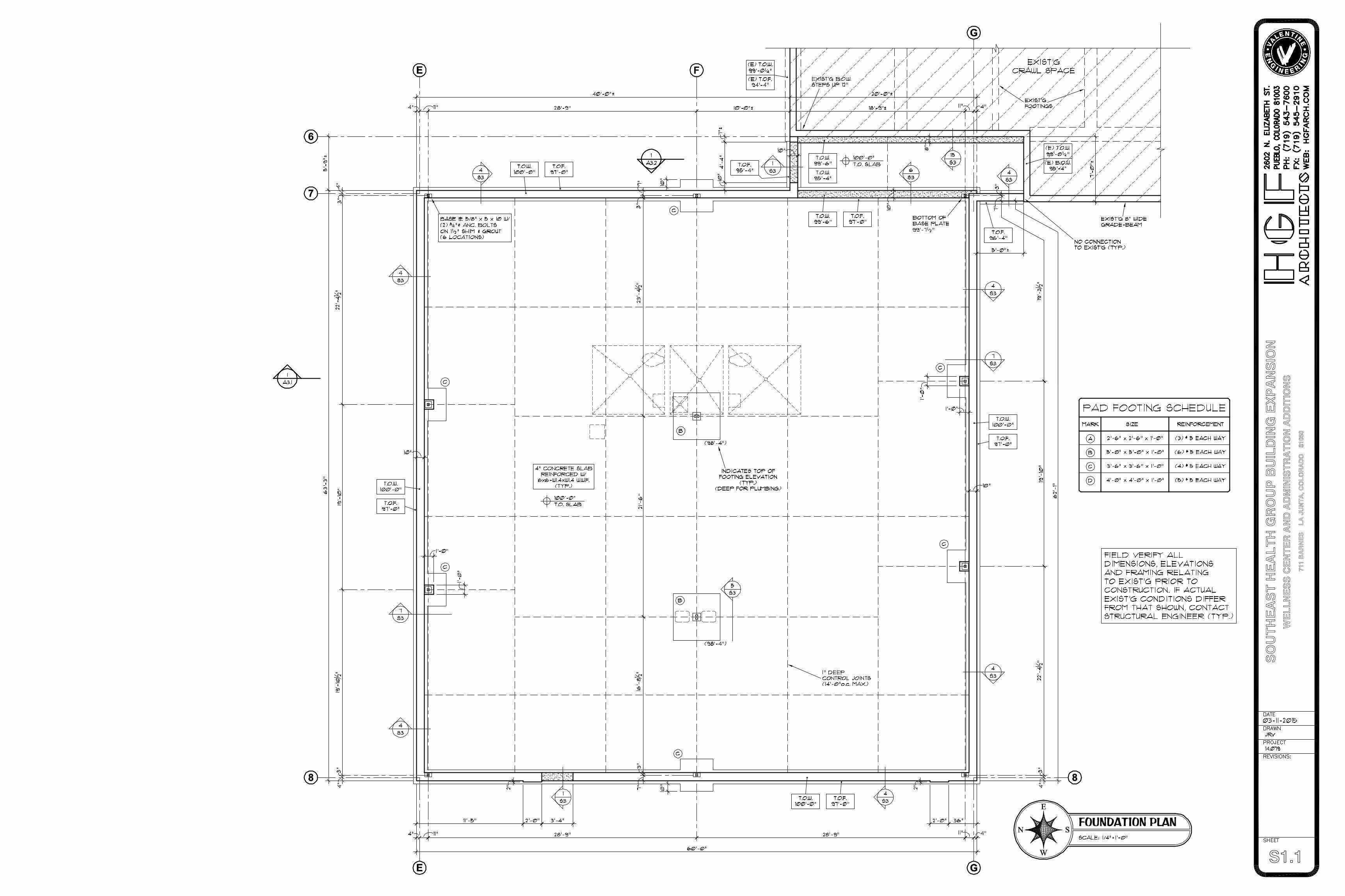
S1.1
F
SO
UT
HE
AS
T H
EA
LT
H G
RO
UP
BU
ILD
ING
EX
PA
NS
ION
WE
LL
NE
SS
CE
NT
ER
AN
D A
DM
INIS
TR
AT
ION
AD
DIT
ION
S71
1 B
AR
NE
S
LA
JU
NT
A, C
OL
OR
AD
O
810
50
S1.2
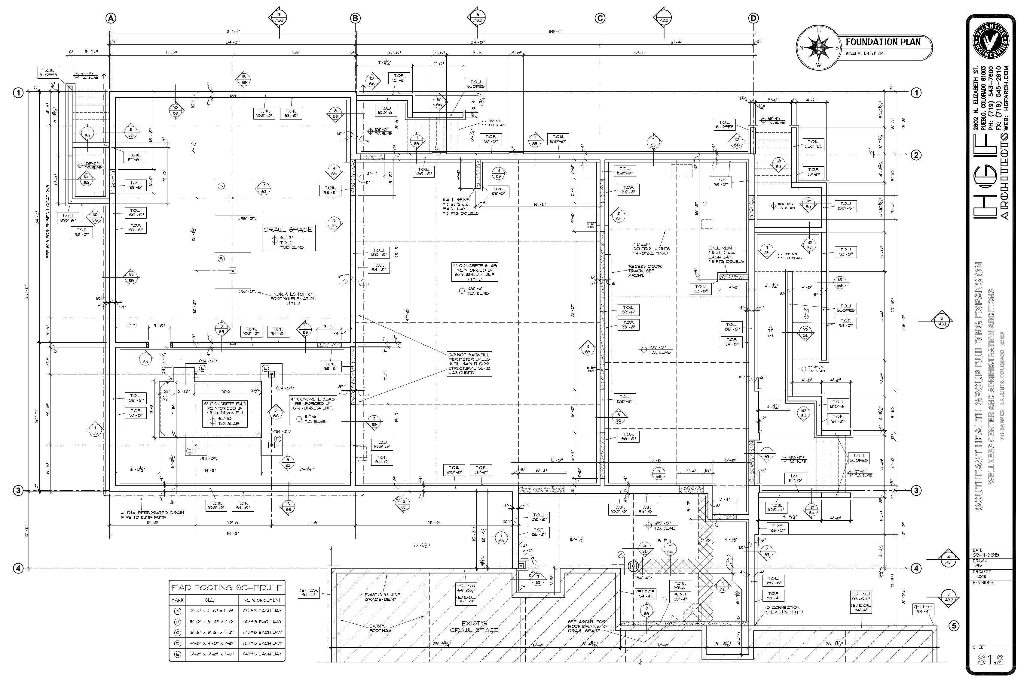
FOUNDATION PLANE
SN
W
4
SO
UT
HE
AS
T H
EA
LT
H G
RO
UP
BU
ILD
ING
EX
PA
NS
ION
WE
LL
NE
SS
CE
NT
ER
AN
D A
DM
INIS
TR
AT
ION
AD
DIT
ION
S71
1 B
AR
NE
S
LA
JU
NT
A, C
OL
OR
AD
O
810
50
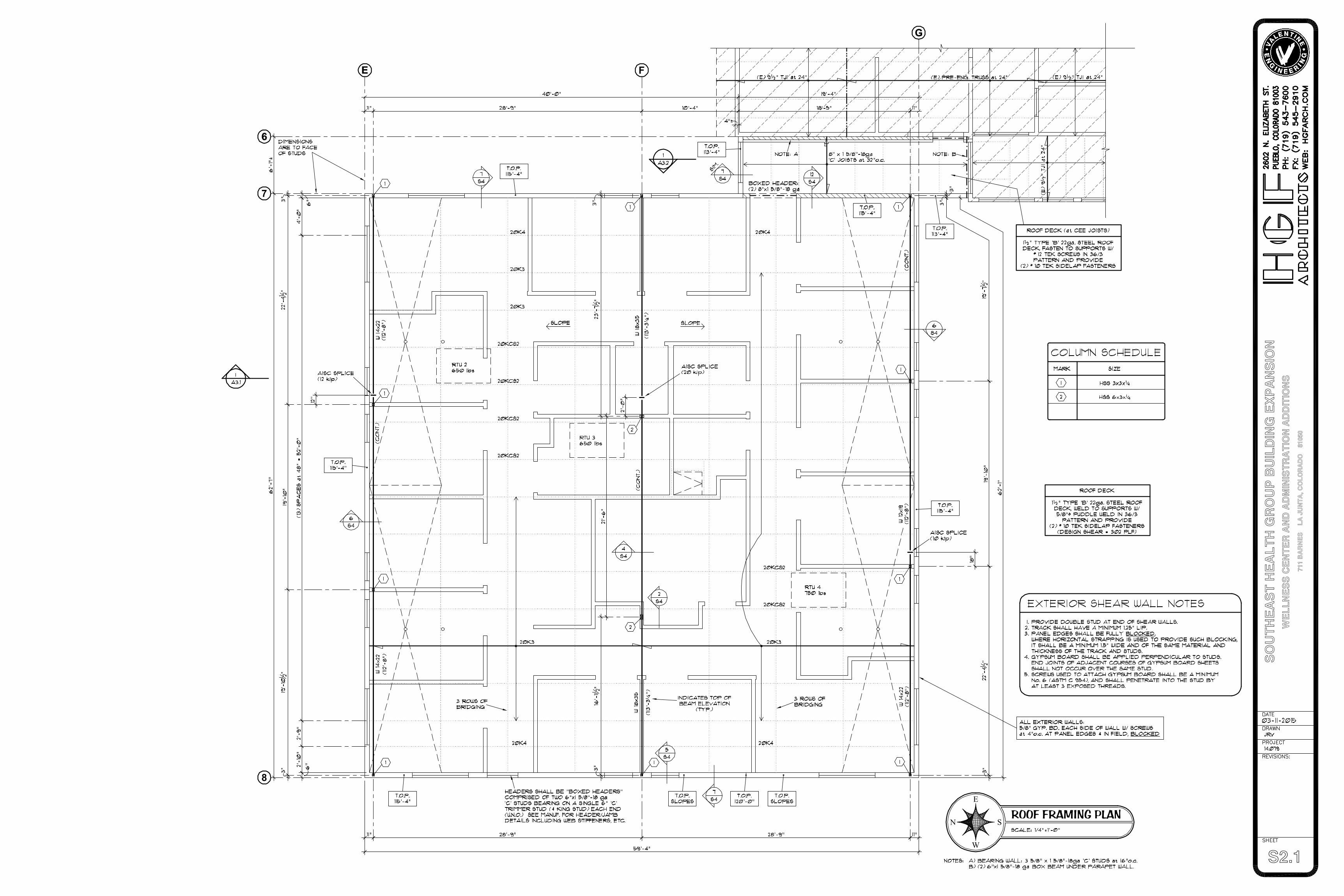
S2.1
ROOF FRAMING PLANE
SN
W
F
7
8
SO
UT
HE
AS
T H
EA
LT
H G
RO
UP
BU
ILD
ING
EX
PA
NS
ION
WE
LL
NE
SS
CE
NT
ER
AN
D A
DM
INIS
TR
AT
ION
AD
DIT
ION
S71
1 B
AR
NE
S
LA
JU
NT
A, C
OL
OR
AD
O
810
50
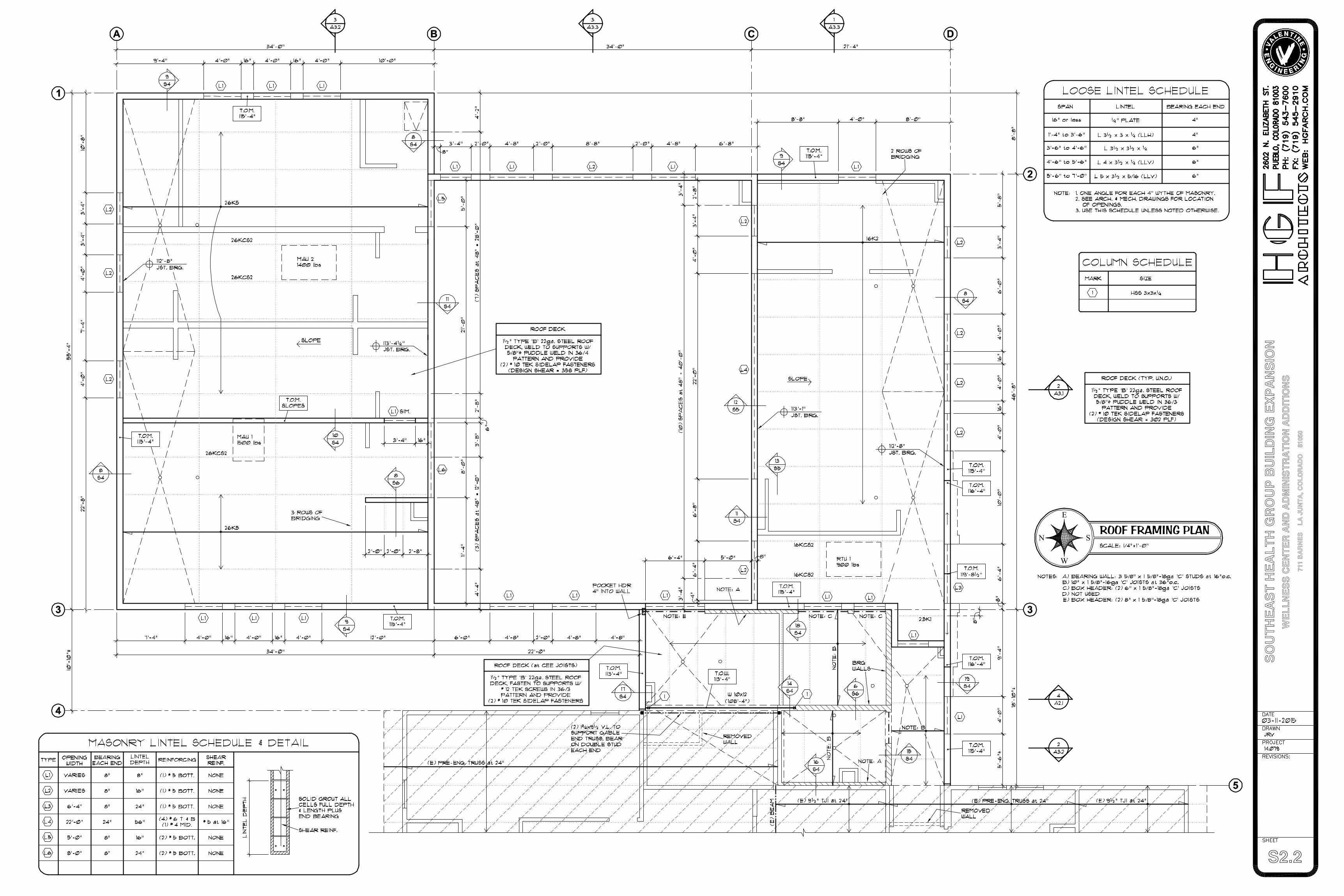
S2.2
ROOF FRAMING PLANE
SN
W
SO
UT
HE
AS
T H
EA
LT
H G
RO
UP
BU
ILD
ING
EX
PA
NS
ION
WE
LL
NE
SS
CE
NT
ER
AN
D A
DM
INIS
TR
AT
ION
AD
DIT
ION
S71
1 B
AR
NE
S
LA
JU
NT
A, C
OL
OR
AD
O
810
50
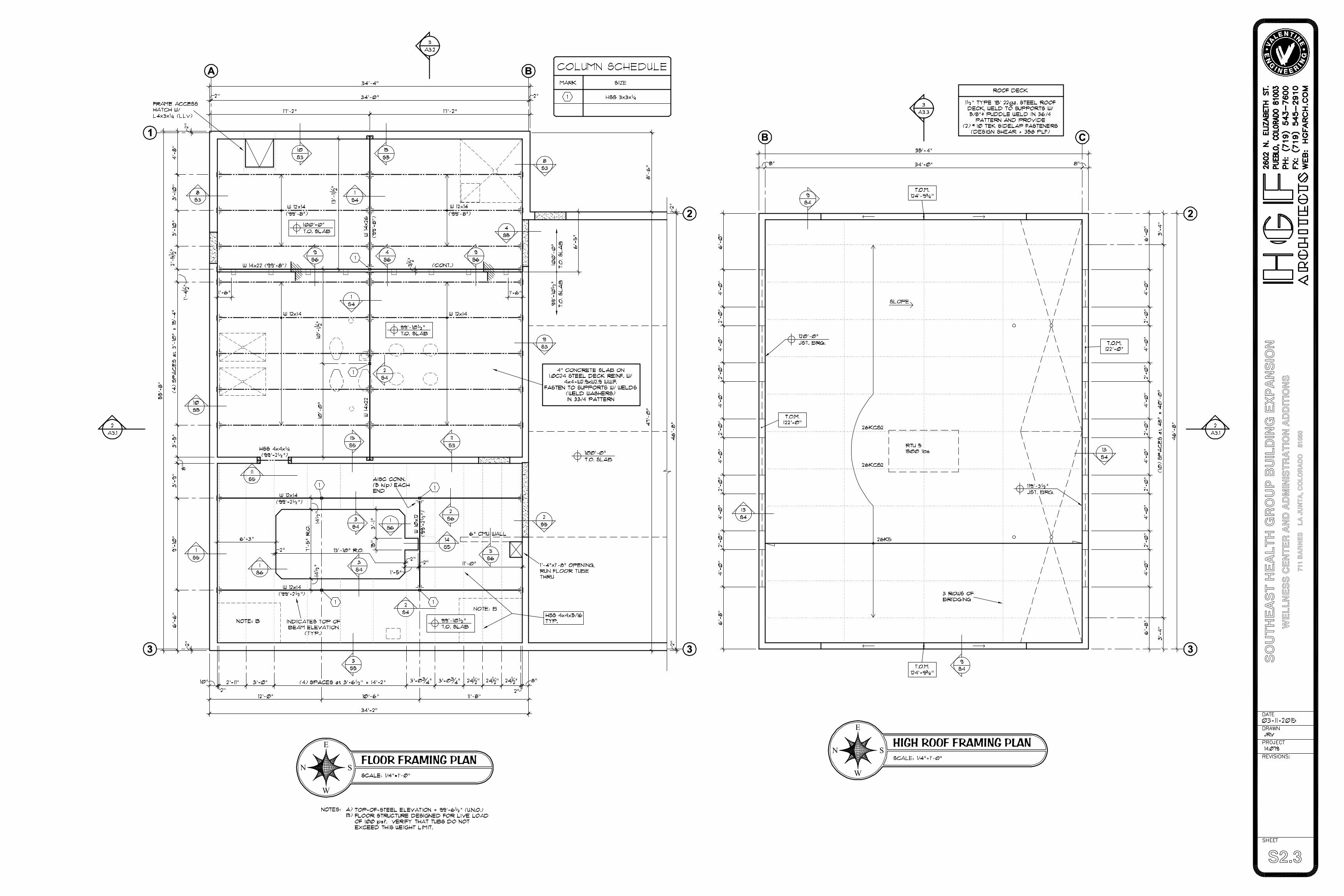
S2.3
HIGH ROOF FRAMING PLANE
SN
WFLOOR FRAMING PLAN
E
SN
W
SO
UT
HE
AS
T H
EA
LT
H G
RO
UP
BU
ILD
ING
EX
PA
NS
ION
WE
LL
NE
SS
CE
NT
ER
AN
D A
DM
INIS
TR
AT
ION
AD
DIT
ION
S71
1 B
AR
NE
S
LA
JU
NT
A, C
OL
OR
AD
O
810
50
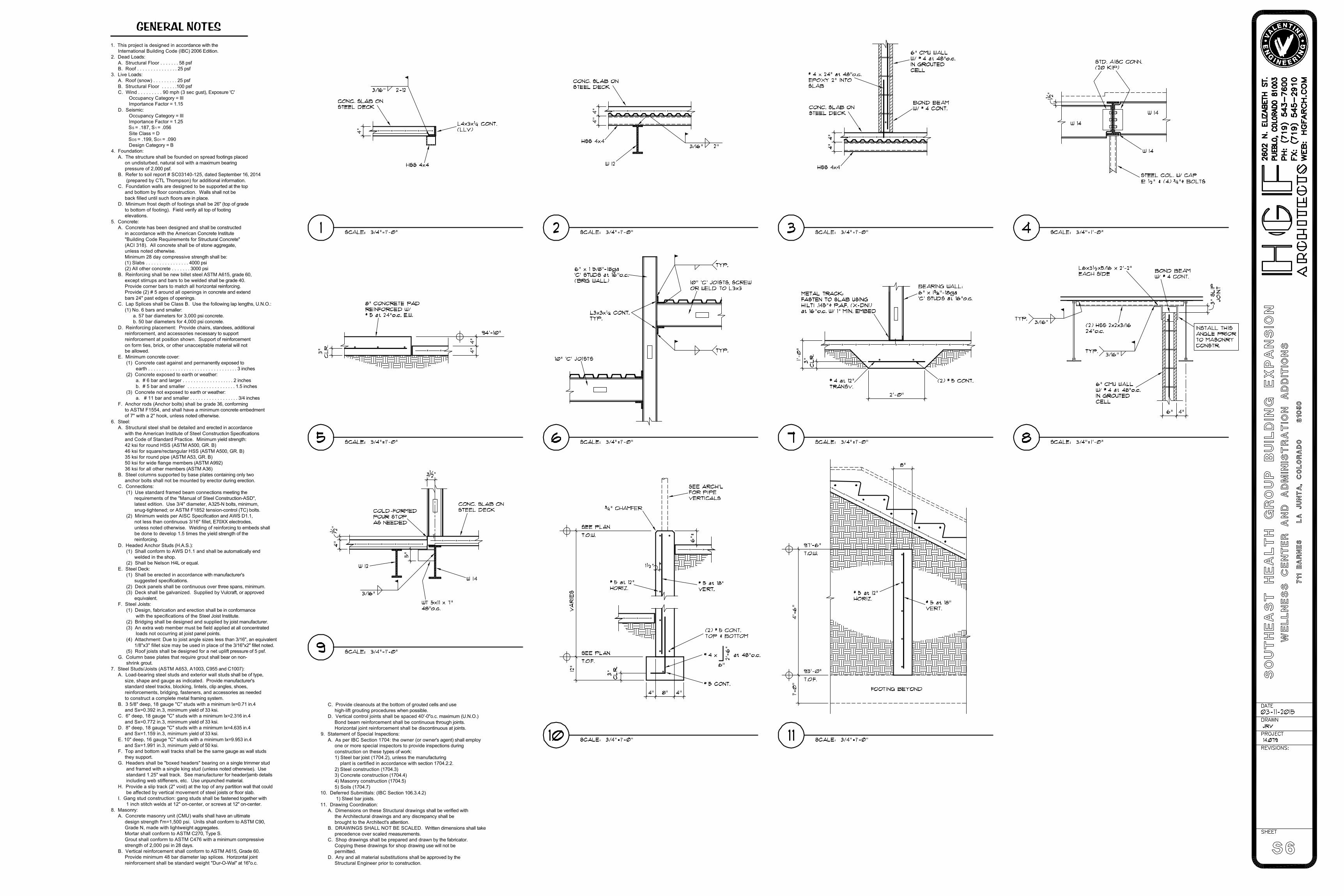
1. This project is designed in accordance with the International Building Code (IBC) 2006 Edition.2. Dead Loads: A. Structural Floor . . . . . . . 58 psf B. Roof . . . . . . . . . . . . . . . 25 psf3. Live Loads: A. Roof (snow) . . . . . . . . . 25 psf B. Structural Floor . . . . . .100 psf C. Wind . . . . . . . . . 90 mph (3 sec gust), Exposure 'C' Occupancy Category = III Importance Factor = 1.15 D. Seismic: Occupancy Category = III Importance Factor = 1.25 SS = .187, S1 = .056 Site Class = D SDS = .199, SD1 = .090 Design Category = B4. Foundation: A. The structure shall be founded on spread footings placed on undisturbed, natural soil with a maximum bearing pressure of 2,000 psf. B. Refer to soil report # SC03140-125, dated September 16, 2014 (prepared by CTL Thompson) for additional information. C. Foundation walls are designed to be supported at the top and bottom by floor construction. Walls shall not be back filled until such floors are in place. D. Minimum frost depth of footings shall be 26" (top of grade to bottom of footing). Field verify all top of footing elevations.5. Concrete: A. Concrete has been designed and shall be constructed in accordance with the American Concrete Institute "Building Code Requirements for Structural Concrete" (ACI 318). All concrete shall be of stone aggregate, unless noted otherwise. Minimum 28 day compressive strength shall be: (1) Slabs . . . . . . . . . . . . . . . . 4000 psi (2) All other concrete . . . . . . . 3000 psi B. Reinforcing shall be new billet steel ASTM A615, grade 60, except stirrups and bars to be welded shall be grade 40. Provide corner bars to match all horizontal reinforcing. Provide (2) # 5 around all openings in concrete and extend bars 24" past edges of openings. C. Lap Splices shall be Class B. Use the following lap lengths, U.N.O.: (1) No. 6 bars and smaller: a. 57 bar diameters for 3,000 psi concrete. b. 50 bar diameters for 4,000 psi concrete. D. Reinforcing placement: Provide chairs, standees, additional reinforcement, and accessories necessary to support reinforcement at position shown. Support of reinforcement on form ties, brick, or other unacceptable material will not be allowed. E. Minimum concrete cover: (1) Concrete cast against and permanently exposed to earth . . . . . . . . . . . . . . . . . . . . . . . . . . . . . . . . . 3 inches (2) Concrete exposed to earth or weather: a. # 6 bar and larger . . . . . . . . . . . . . . . . . . . 2 inches b. # 5 bar and smaller . . . . . . . . . . . . . . . . . . 1.5 inches (3) Concrete not exposed to earth or weather: a. # 11 bar and smaller . . . . . . . . . . . . . . . . . . 3/4 inches F. Anchor rods (Anchor bolts) shall be grade 36, conforming to ASTM F1554, and shall have a minimum concrete embedment of 7" with a 2" hook, unless noted otherwise.6. Steel: A. Structural steel shall be detailed and erected in accordance with the American Institute of Steel Construction Specifications and Code of Standard Practice. Minimum yield strength: 42 ksi for round HSS (ASTM A500, GR. B) 46 ksi for square/rectangular HSS (ASTM A500, GR. B) 35 ksi for round pipe (ASTM A53, GR. B) 50 ksi for wide flange members (ASTM A992) 36 ksi for all other members (ASTM A36) B. Steel columns supported by base plates containing only two anchor bolts shall not be mounted by erector during erection. C. Connections: (1) Use standard framed beam connections meeting the requirements of the "Manual of Steel Construction-ASD", latest edition. Use 3/4" diameter, A325-N bolts, minimum, snug-tightened; or ASTM F1852 tension-control (TC) bolts. (2) Minimum welds per AISC Specification and AWS D1.1, not less than continuous 3/16" fillet, E70XX electrodes, unless noted otherwise. Welding of reinforcing to embeds shall be done to develop 1.5 times the yield strength of the reinforcing. D. Headed Anchor Studs (H.A.S.): (1) Shall conform to AWS D1.1 and shall be automatically end welded in the shop. (2) Shall be Nelson H4L or equal. E. Steel Deck: (1) Shall be erected in accordance with manufacturer's suggested specifications. (2) Deck panels shall be continuous over three spans, minimum. (3) Deck shall be galvanized. Supplied by Vulcraft, or approved equivalent. F. Steel Joists: (1) Design, fabrication and erection shall be in conformance with the specifications of the Steel Joist Institute. (2) Bridging shall be designed and supplied by joist manufacturer. (3) An extra web member must be field applied at all concentrated loads not occurring at joist panel points. (4) Attachment: Due to joist angle sizes less than 3/16", an equivalent 1/8"x3" fillet size may be used in place of the 3/16"x2" fillet noted. (5) Roof joists shall be designed for a net uplift pressure of 5 psf. G. Column base plates that require grout shall bear on non- shrink grout.7. Steel Studs/Joists (ASTM A653, A1003, C955 and C1007): A. Load-bearing steel studs and exterior wall studs shall be of type, size, shape and gauge as indicated. Provide manufacturer's standard steel tracks, blocking, lintels, clip angles, shoes, reinforcements, bridging, fasteners, and accessories as needed to construct a complete metal framing system. B. 3 5/8" deep, 18 gauge "C" studs with a minimum Ix=0.71 in.4 and Sx=0.392 in.3, minimum yield of 33 ksi. C. 6" deep, 18 gauge "C" studs with a minimum Ix=2.316 in.4 and Sx=0.772 in.3, minimum yield of 33 ksi. D. 8" deep, 18 gauge "C" studs with a minimum Ix=4.635 in.4 and Sx=1.159 in.3, minimum yield of 33 ksi. E. 10" deep, 16 gauge "C" studs with a minimum Ix=9.953 in.4 and Sx=1.991 in.3, minimum yield of 50 ksi. F. Top and bottom wall tracks shall be the same gauge as wall studs they support. G. Headers shall be "boxed headers" bearing on a single trimmer stud and framed with a single king stud (unless noted otherwise). Use standard 1.25" wall track. See manufacturer for header/jamb details including web stiffeners, etc. Use unpunched material. H. Provide a slip track (2" void) at the top of any partition wall that could be affected by vertical movement of steel joists or floor slab. I. Gang stud construction: gang studs shall be fastened together with 1 inch stitch welds at 12" on-center, or screws at 12" on-center.8. Masonry: A. Concrete masonry unit (CMU) walls shall have an ultimate design strength f'm=1,500 psi. Units shall conform to ASTM C90, Grade N, made with lightweight aggregates. Mortar shall conform to ASTM C270, Type S. Grout shall conform to ASTM C476 with a minimum compressive strength of 2,000 psi in 28 days. B. Vertical reinforcement shall conform to ASTM A615, Grade 60. Provide minimum 48 bar diameter lap splices. Horizontal joint reinforcement shall be standard weight "Dur-O-Wal" at 16"o.c.
GENERAL NOTES
C. Provide cleanouts at the bottom of grouted cells and use high-lift grouting procedures when possible. D. Vertical control joints shall be spaced 40'-0"o.c. maximum (U.N.O.) Bond beam reinforcement shall be continuous through joints. Horizontal joint reinforcement shall be discontinuous at joints.9. Statement of Special Inspections: A. As per IBC Section 1704: the owner (or owner's agent) shall employ one or more special inspectors to provide inspections during construction on these types of work: 1) Steel bar joist (1704.2), unless the manufacturing plant is certified in accordance with section 1704.2.2. 2) Steel construction (1704.3) 3) Concrete construction (1704.4) 4) Masonry construction (1704.5) 5) Soils (1704.7)10. Deferred Submittals: (IBC Section 106.3.4.2) 1) Steel bar joists.11. Drawing Coordination: A. Dimensions on these Structural drawings shall be verified with the Architectural drawings and any discrepancy shall be brought to the Architect's attention. B. DRAWINGS SHALL NOT BE SCALED. Written dimensions shall take precedence over scaled measurements. C. Shop drawings shall be prepared and drawn by the fabricator. Copying these drawings for shop drawing use will not be permitted. D. Any and all material substitutions shall be approved by the Structural Engineer prior to construction.
S7
F
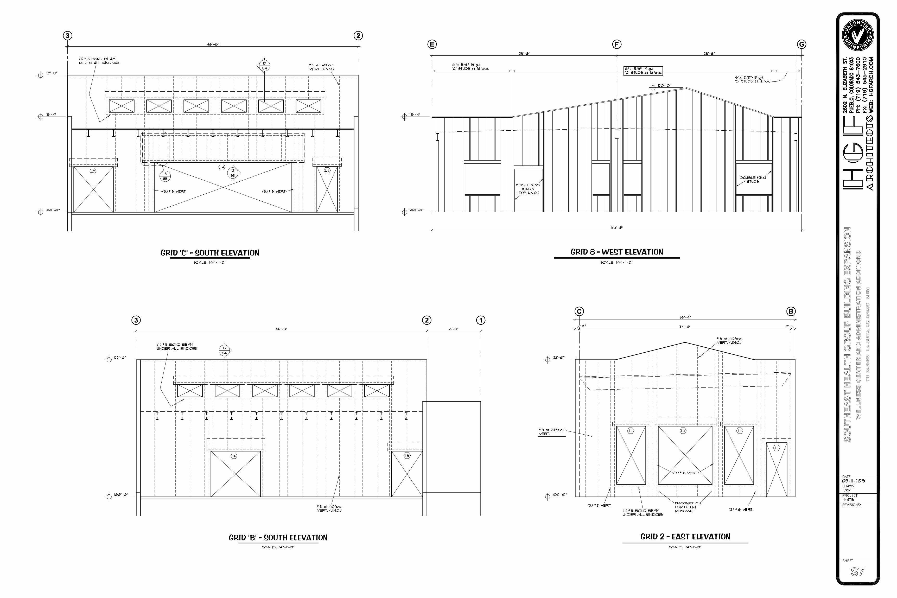
GRID 'B' - SOUTH ELEVATION
SO
UT
HE
AS
T H
EA
LT
H G
RO
UP
BU
ILD
ING
EX
PA
NS
ION
WE
LL
NE
SS
CE
NT
ER
AN
D A
DM
INIS
TR
AT
ION
AD
DIT
ION
S71
1 B
AR
NE
S
LA
JU
NT
A, C
OL
OR
AD
O
810
50