Embed Size (px)
Citation preview
AUGUST 2005
SOUTHDOWN MAGNETITE IRON ORE PROJECT
ALBANY PORT UPGRADE DIVE SAMPLING REPORT

GRANGE RESOURCES SOUTHDOWN MAGNETITE IRON ORE PROJECT
ALBANY PORT UPGRADE DIVE SAMPLING REPORT AUGUST 2005
Prepared for
By
Note: This report has been prepared as part of the Bankable Feasibility Study for Grange Resources’ Southdown Project and the associated Albany Port Upgrade. The information, assumptions and conclusions contained herein are confidential and should not be relied upon or used for any other purpose. JFA Consultants does not warrant the accuracy of information, assumptions or conclusions in anyway whatsoever.
Rev Issue Prepared by Submitted to Date Copies
A Draft – Internal Review Brendon Brodie-Hall Tim Green 25/08/05 1 0 Initial Client Issue BBH Neil Marston 29/08/05 1
1 Revised Client Issue BBH Brad Williamson 8/09/05 1
2 Final BBH
Brad Williamson Neil Marston Valarie Ee Peter Morrison
12/09/05 1
Document Information File Path: Z:\Business\National\GRANGE Resources Southdown\Dive Sampling August 2005\050807 Grange-APA dive sampling report rev2.doc
Southdown Magnetite Iron Ore Project – Albany Port Upgrade Dive Sampling Report
TABLE OF CONTENTS
1. BACKGROUND .................................................................................................................... 1
2. METHODOLOGY AND EQUIPMENT ................................................................................... 2
3. RESULTS.............................................................................................................................. 3
4. TESTING ............................................................................................................................... 5 APPENDIX A SUMMARY SPREADSHEET APPENDIX B DRAWINGS APPENDIX C LABORATORY TESTING RESULTS (COFFEY GEOSCIENCES)

Southdown Magnetite Iron Ore Project – Albany Port Upgrade Dive Sampling Report
Page 1
1. BACKGROUND
Grange Resources is undertaking a Bankable Feasibility Study for their Southdown Magnetite Iron Ore Project on the south coast of Western Australia. The current proposal is for mined ore to be transported a distance of approximately 100km in slurry form through a pipeline from the minesite (near Wellstead) to the Port of Albany. The slurry will then be dewatered and stockpiled before loading into Cape size vessels for shipment overseas. The Port of Albany will require a significant upgrade to facilitate this process, including the construction of a new berth (Berth No.7) and dredging of a new channel from Princess Royal Harbour into King George Sound. Following an initial desktop investigation into the feasibility of dredging, a dive probing campaign was carried out in late January / early February 2005. The results of this campaign are provided in a separate report (Southdown Magnetite Iron Ore Project – Dive Probing Report, JFA Consultants, March 2005). The results of this initial dive probing report indicated that the presence of rock above the design dredge depth may be less of a problem than had been initially anticipated, although the area around Gio Batta Patch and between the heads at Princess Royal Harbour remained of some concern due to shallow refusal from the probing. Fugro Survey Pty Ltd was subsequently commissioned by Grange to carry out a seismic reflection survey along the alignment of the proposed channel. The survey was carried out between 9 and 19 May 2005 and was comprised of single beam echo sounding, side scan sonar and sub-bottom profiling. This survey indicated that fresh granitic bedrock would generally be located well below the Option 1 Design Dredge depth, although a “Horizon A” layer may outcrop above the design dredge depth and may consist of clayey sediments with granite boulders within the matrix. As part of the environmental approvals process for the project, it is necessary to develop a model of the proposed dredging campaign to determine the likely extent of turbidity and possible impacts on the marine environment. Grange has engaged Global Earth Modelling Systems (GEMS) to carry out this modelling. Various meteorological and oceanographic instruments have been deployed in King George Sound and Princess Royal Harbour to collect data to input into the GEMS model. Bathymetric data is already available and a typical dredge program will be provided to model the situation. The remaining required input is in regard to the nature of the material to be dredged. The original intention had been for this information to be obtained from Vibrocores due to be carried out in October 2005, however this timing is considered to be too late in terms of the environmental approvals process and it was therefore decided to proceed with an alternative method of obtaining sub-bottom samples. A method of obtaining samples of unconsolidated material at depth was developed jointly by JFA and Albany based Southcoast Diving Supplies. This method is outlined in more detail in Section 2. The aim of the exercise was to obtain representative samples of the material to be dredged along the full length of the proposed channel in King George Sound.
Southdown Magnetite Iron Ore Project – Albany Port Upgrade Dive Sampling Report
Page 2
2. METHODOLOGY AND EQUIPMENT
The following equipment was mobilised to carry out the sampling campaign; • Workboat MV Stackpool, owned and operated by Albany Tug Services (skipper Colin Bairstow,
deckhand Jason Bairstow). • Four man commercial dive team, provided by Southcoast Diving Supplies. Divers operated with
SCUBA equipment and communicated with the boat via a life-line (ie 1 pull for attention, 2 pulls to start pump, 3 pulls to stop pump, etc).
• 1.5” Robin water pump and 40m of fire-hose, hired from Bertola Hire. • 50mm PVC pipe of varying length, including all necessary fittings and caps. • Garmin GPS coupled to Toshiba notebook computer for horizontal positioning.
Supervision and management of the dive team was provided by Garry Wellstead, owner of Southcoast Diving Supplies. Brendon Brodie-Hall, engineer from JFA Consultants, was present for the duration of the campaign to supervise and manage on behalf of Grange and APA. The typical procedure for obtaining samples was as follows:
1. Locate sample location by GPS and position the vessel using bow and stern anchors. 2. Deploy 2 divers at each location. 3. The divers had three probes of varying lengths at their disposal, 1.5m, 3m and 4.5m. To obtain a
sample from 0 to 1.0m, the 1.5m probe would be hammered in using a device similar to a fence post hammer. To obtain a sample from 1.0m to 2.0m, the 3m probe would be jetted in the top 1.0m (ie using the pump on board the workboat) and then hammered in the remaining distance. To obtain a sample from say 2.5m to 3.5m, the 4.5m probe would be jetted in the top 2.5m and then hammered in the remaining distance. The sampling increments were not uniform across all sites due to variability in the depth and hardness of material layers.
4. Irrespective of the sampling depth, to remove the probe (and sample) the top of the probe was capped and the probe extracted by pulling vertically. Where the probe could not be extracted by physical force, a secondary probe was used to jet around the primary probe to loosen the surrounding material. In some cases the probe could not be extracted even with assistance by jetting and in these cases the probe had to be cut off at the seafloor.
5. The divers would bring the probes (with samples inside) to the surface and the contents of each would be transferred into separate plastic containers on the deck of the workboat. The mixture was allowed to settle and the excess water then drained off. The material from each sample would then be manually transferred into a labelled polythene sample bag and the bag sealed by twisting and tying with plastic cable tie.
Where visibility and practicalities permitted, the divers took photographs of the seafloor at the location of each sample. The horizontal accuracy of the sample locations is estimated to be +/- 10 metres and the vertical accuracy of the probe depths is estimated to be +/- 200mm. Both tolerances are considered sufficient for the purposes of the sampling.

Southdown Magnetite Iron Ore Project – Albany Port Upgrade Dive Sampling Report
Page 3
3. RESULTS
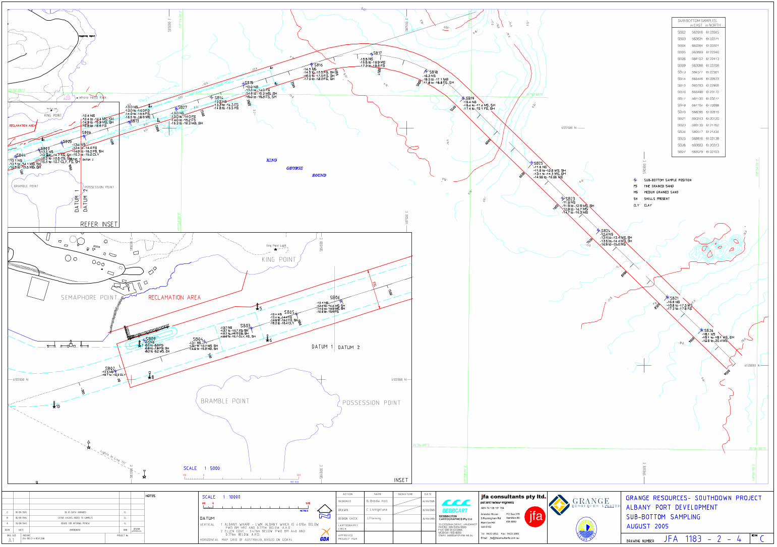
The sampling campaign was undertaken from Tuesday 9th August to midday on Thursday 11th August 2005. This coincided with a period of excellent weather in Albany, with low swell and seas in King George Sound, which was ideal for the sampling campaign. The sampling locations for this campaign are designated using “SB” nomenclature. The sampling locations were principally derived from the proposed vibrocoring locations, many of which were proposed by Fugro following the seismic reflection survey. Refer to Drg JFA 1183-2-4 in Appendix A for the sampling locations. Sampling commenced at the offshore end of the channel on the morning of 9th August. Sampling at the first few locations was relatively time consuming as the respective dive pairs became accustomed to the process. It should also be noted that a relatively hard layer was encountered at sites VC21 and VC23 (in the general vicinity of the Gio Batta Patch) which slowed progress. A total of seven locations were sampled on Day 1 working shorewards along the channel, the last site being VC15 on the shoreward side of the channel bend. A total of eight locations were sampled on Day 2, starting at VC14 and finishing at VC2 at the start of the channel. Whilst the efficiency of the dive operation was generally improved on Day 2, the presence of clay at depth slowed the process as considerable effort was required to insert and extract the probes wherever clay was present. At the end of Day 2, the weather forecast was examined and it was decided to proceed with a further half day of sampling. A further four locations were sampled on Day 3, working shorewards from the end of the channel filling in between existing sample locations. The seabed at most location was described by the divers as being sandy with patches of seagrass interspersed across the seabed but never in thick meadows. Figure 1 below is a photo taken at location VC23 showing the inserted probe and the surrounding seabed. This is considered typical of the seabed in the proposed channel to be dredged in King George Sound.
Figure 1 - Photo taken at the seabed at VC23. Sample tube inserted approximately 2.5m.

Southdown Magnetite Iron Ore Project – Albany Port Upgrade Dive Sampling Report
Page 4
With respect to the sub-bottom material characteristics, the predominant material type was a clean grey fine to medium grained sand. At depths around -15m CD in the east-west channel alignment, a green clay with high plasticity was encountered that was very difficult to sample, with the PVC probes tending to become immovable once inserted into the clay. This material was found at higher depths (approximately -13m CD) in Princess Royal Harbour. Further out along the channel, some samples contained relatively high shell content. There was no trend as to the depth at which high shell content samples were obtained; some were above the grey sand layer and some were below the grey sand layer. Samples with high shell content were often brown or yellow in colour. At VC25, near the Gio Batta patch, loose limestone rocks were present on the seafloor.
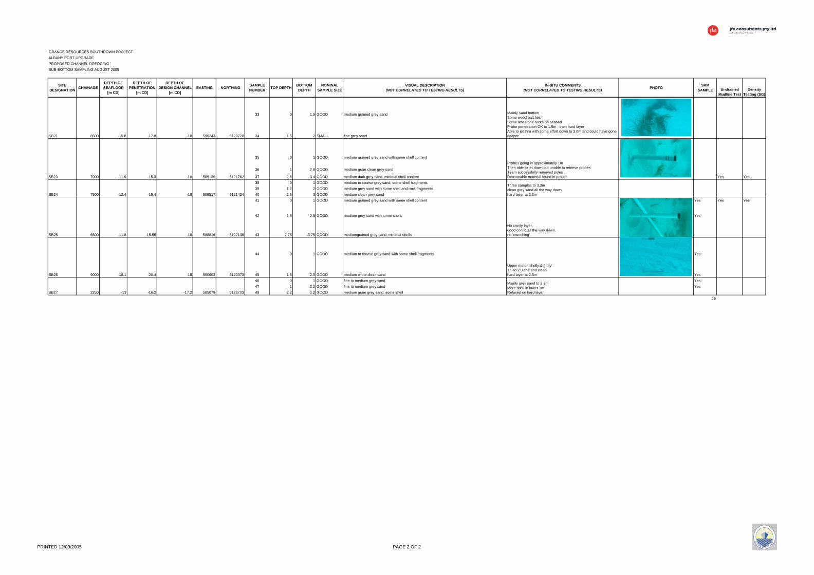
At most locations at least two samples were able to be taken, and in many cases three samples were obtained. It was therefore possible to obtain a good representation of the material to be dredged down two to three metres below the seabed in most areas. At the time of writing of this report, the Option 1 channel design is shaping to be the most likely in terms of how the project will proceed. The depth of sampling and the current Option 1 design depths are plotted against channel chainage in Figure 2 to provide an indication of the extent of material sampling during this exercise. It should be noted that this design profile is preliminary only and is yet to be verified by under keel clearance studies. A summary spreadsheet of the sampling program, including co-ordinates, depths, descriptions and photos is provided in Appendix A.
Grange Resources - Albany Port UpgradeSub-bottom Sampling August 2005
Sampling Depth vs Option 1 Design Channel Profile
-22
-20
-18
-16
-14
-12
-10
-8
-6
-4
-2
00 1000 2000 3000 4000 5000 6000 7000 8000 9000
Chainage [m]
Dep
th b
elow
Cha
rt D
atum
[m C
D]
Option 1 Design Profile Existing Seabed Depth of Sampling
Figure 2 - Option 1 channel profile plotted against sampling depth.

Southdown Magnetite Iron Ore Project – Albany Port Upgrade Dive Sampling Report
Page 5
4. TESTING
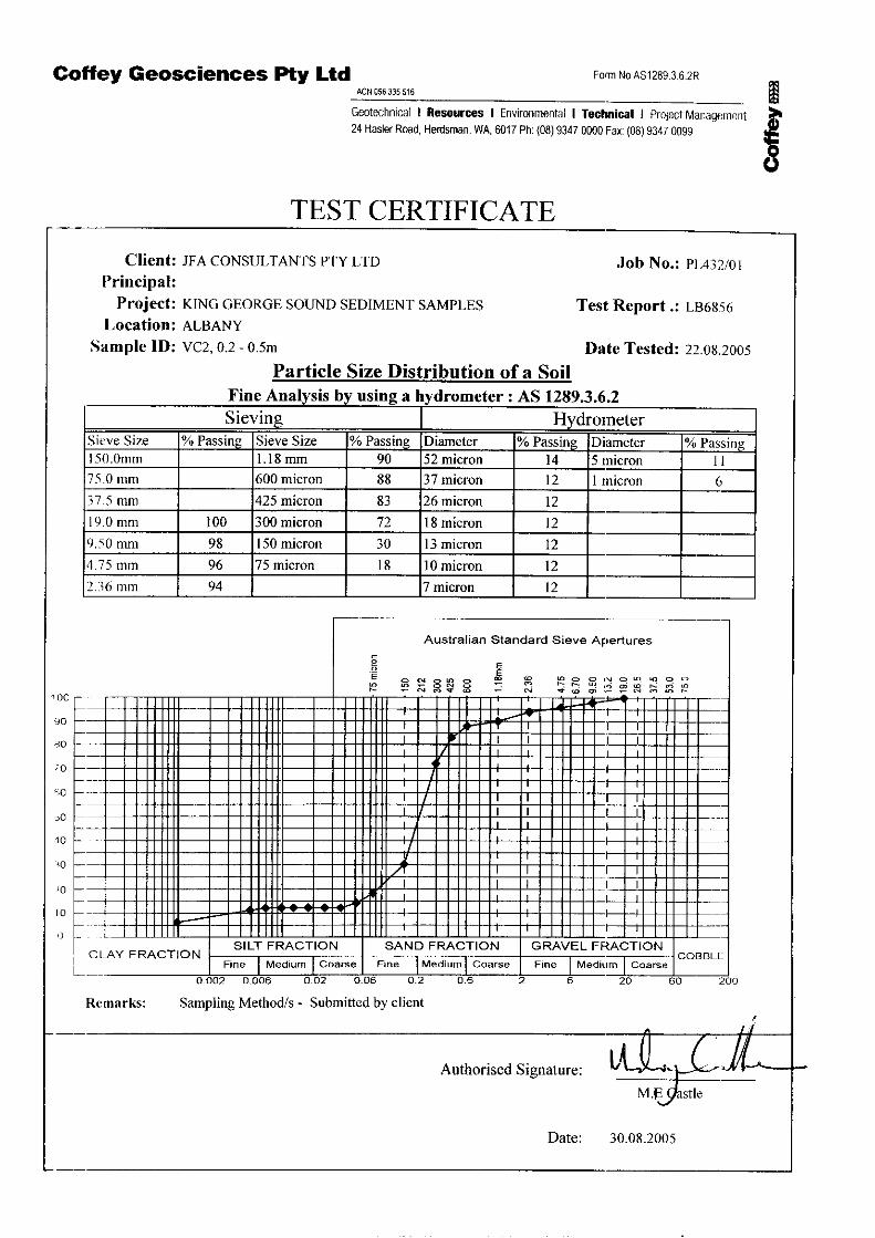
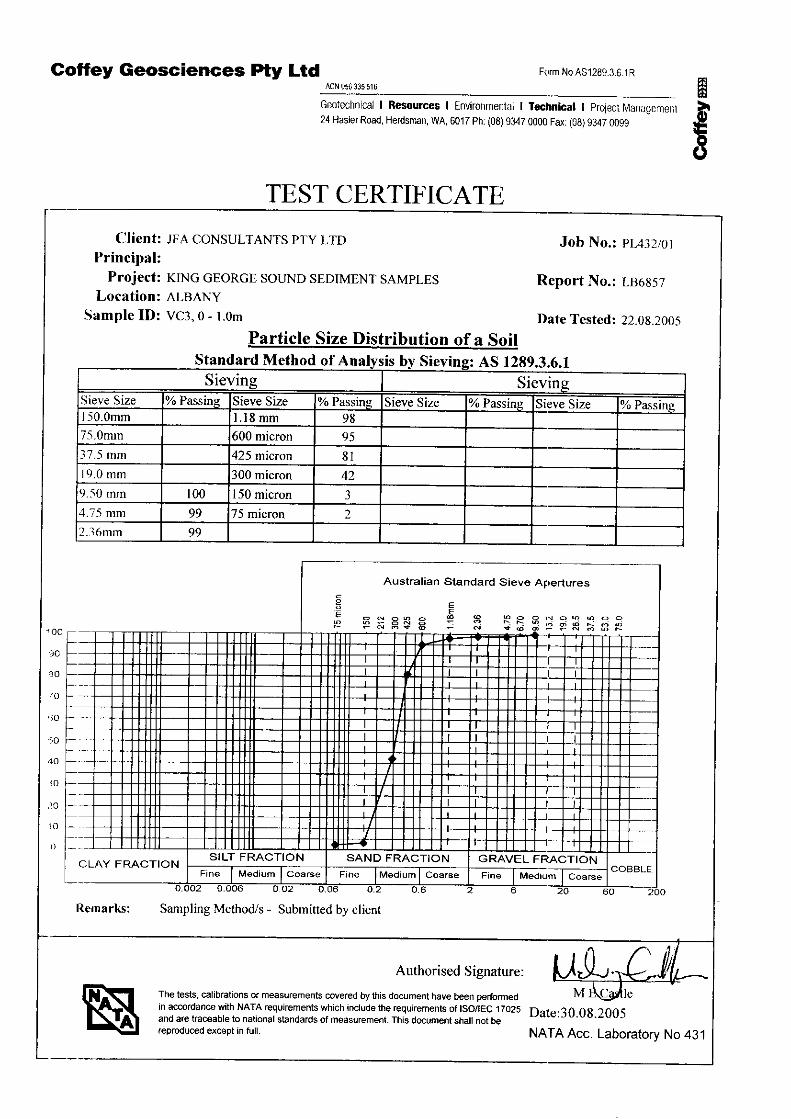
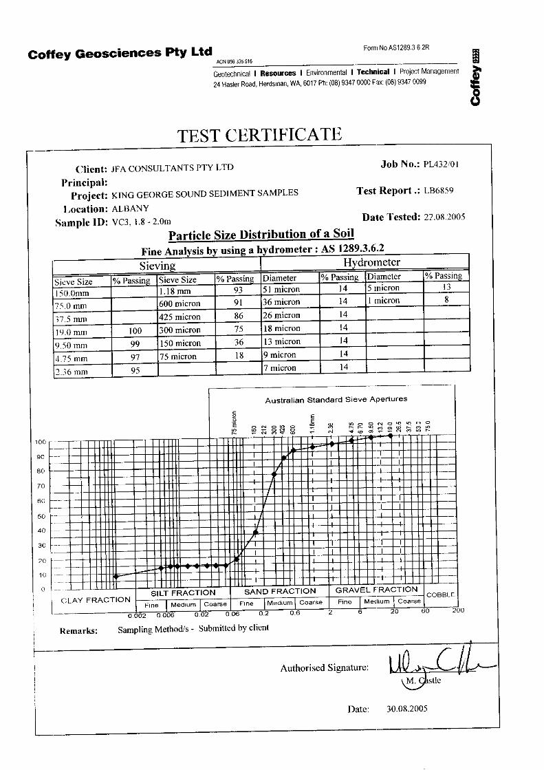
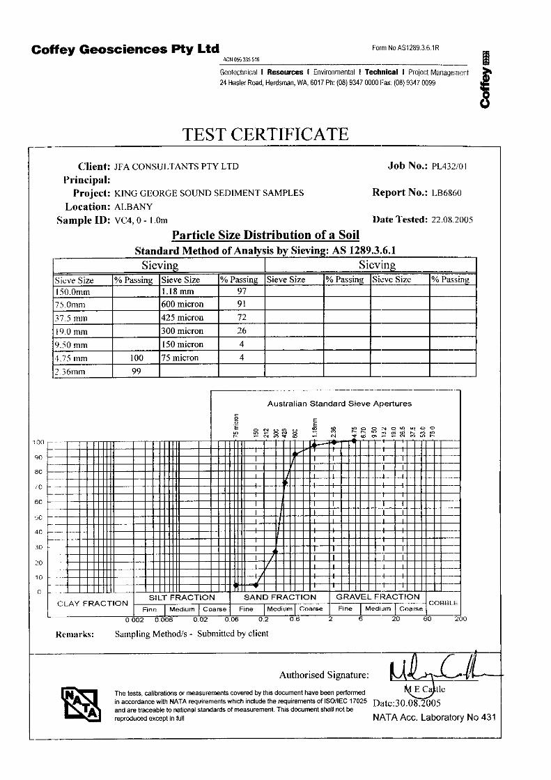
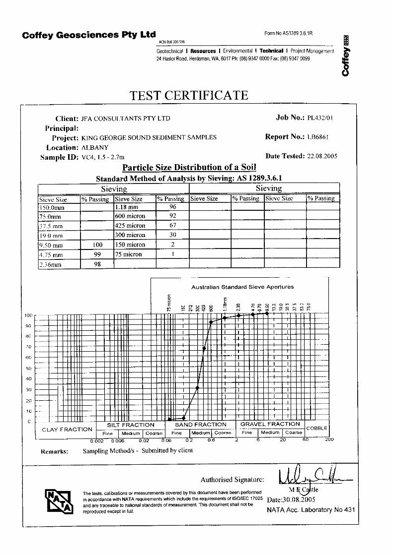
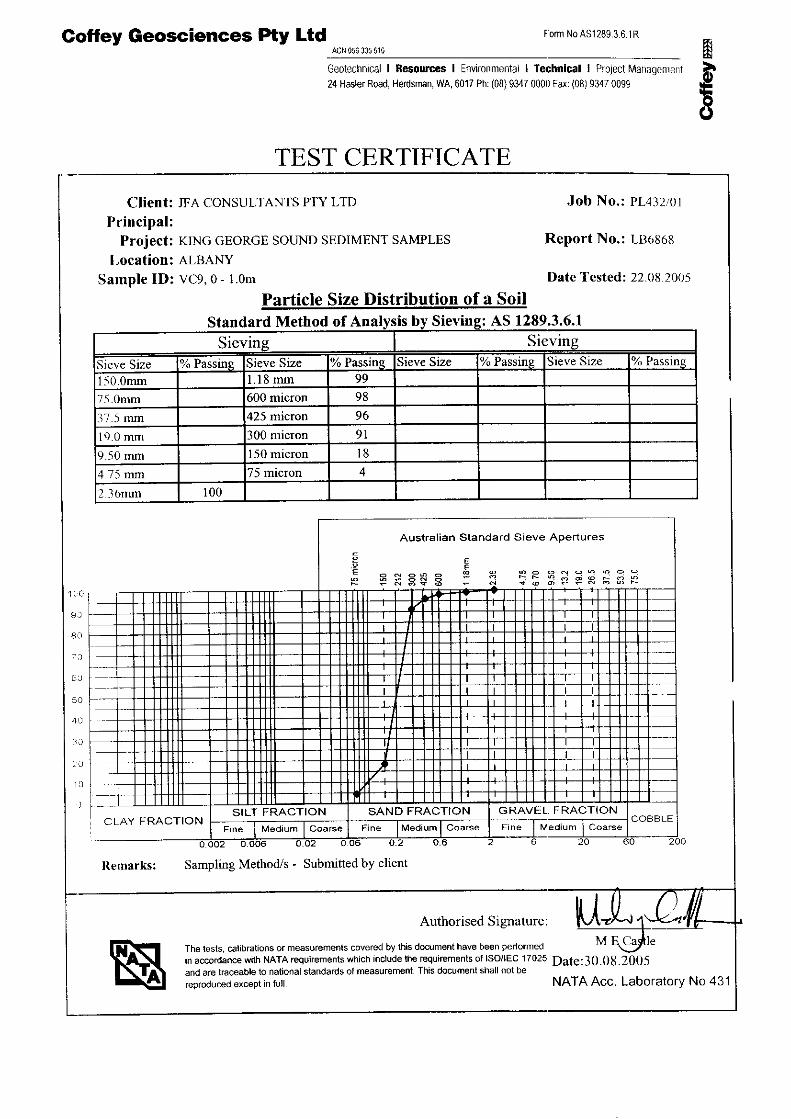
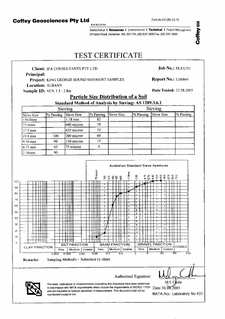
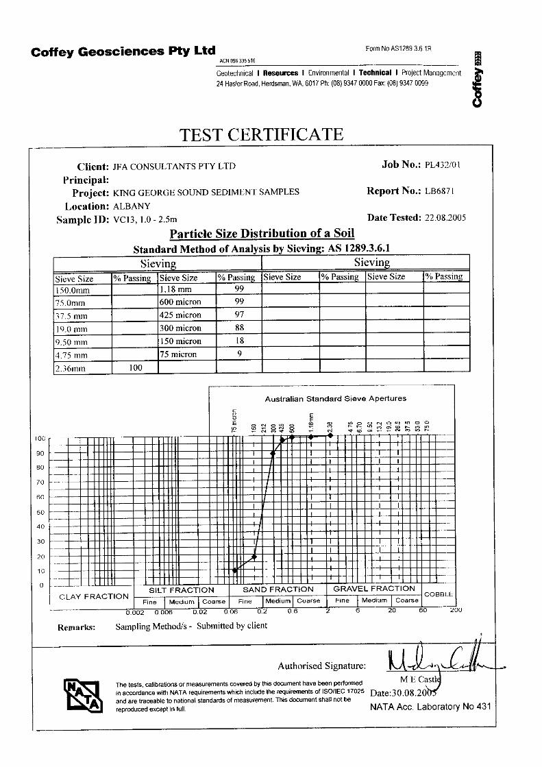
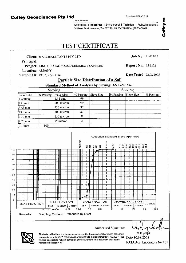
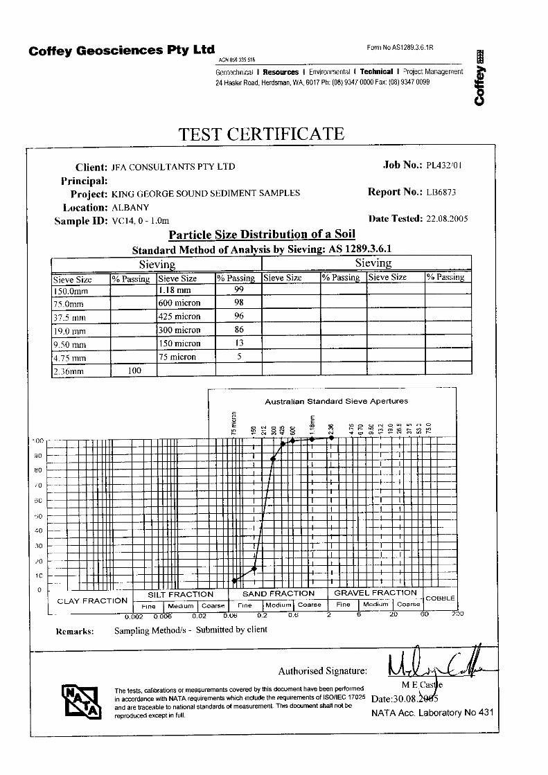
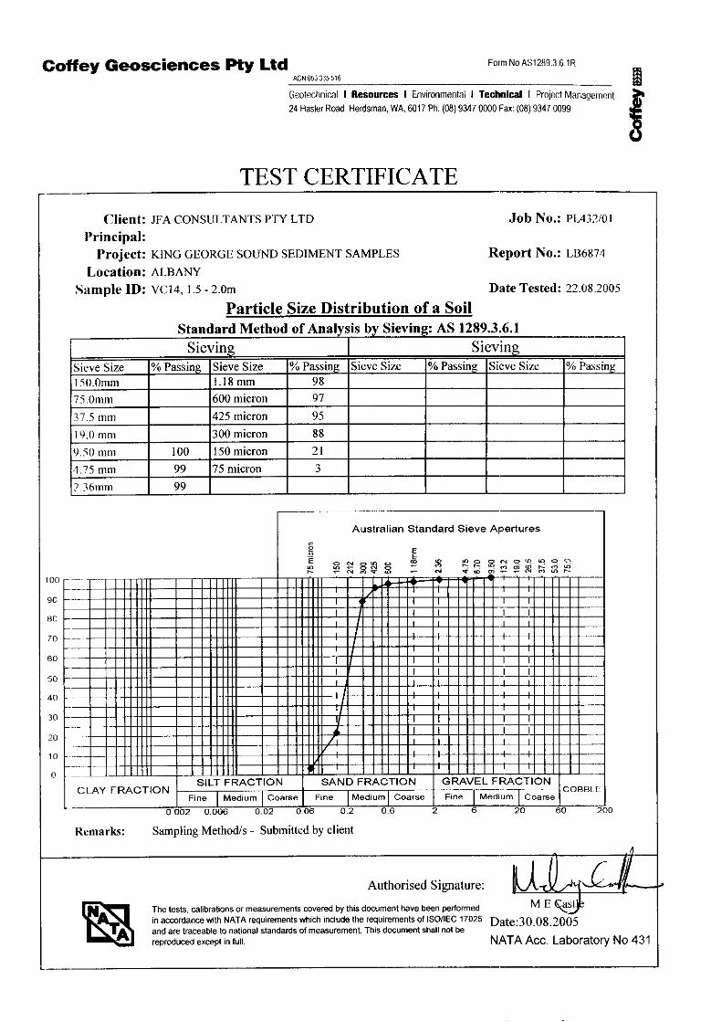
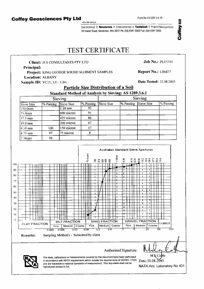
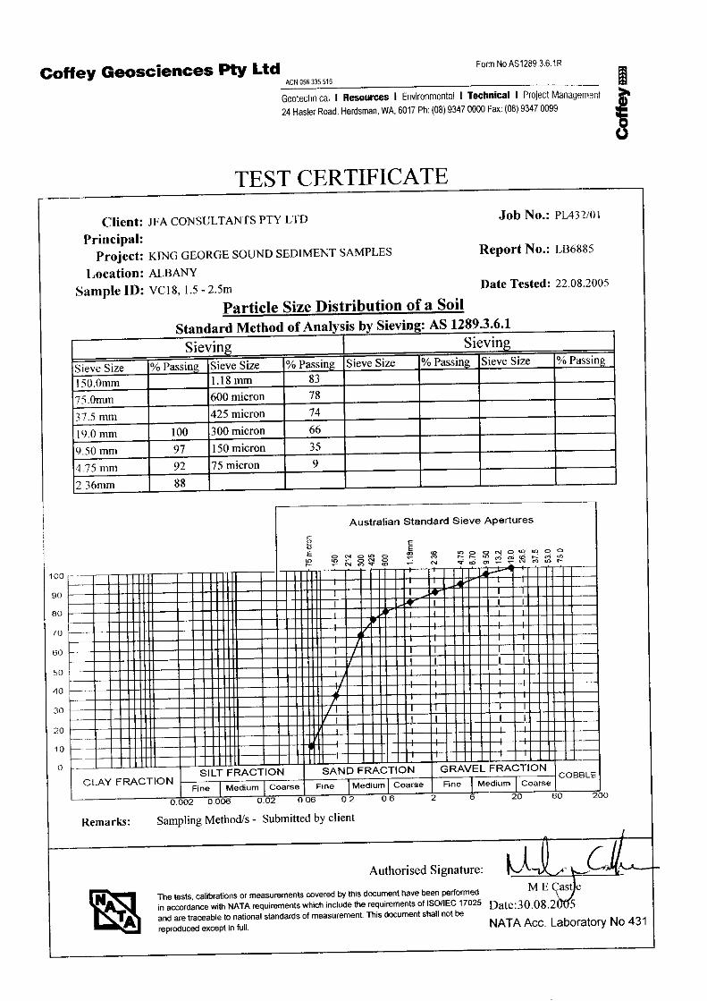
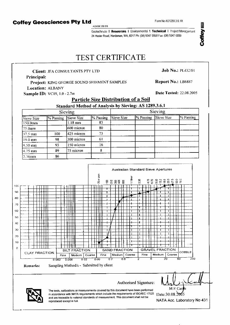
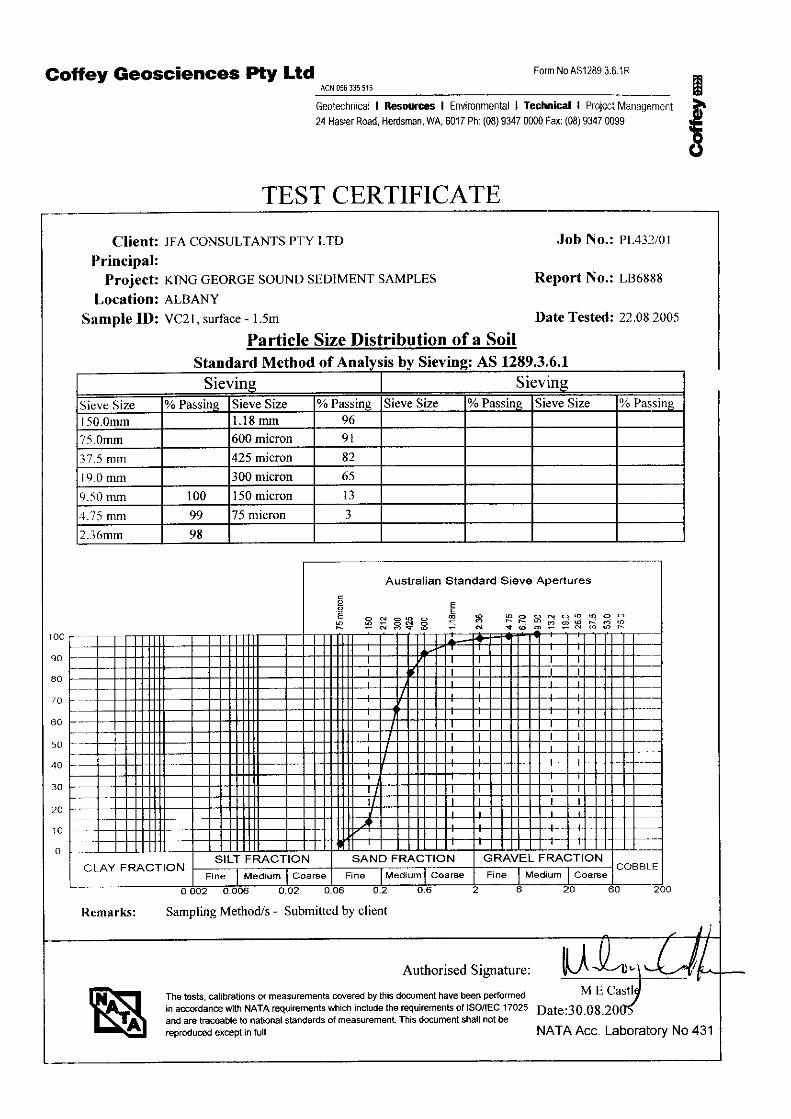
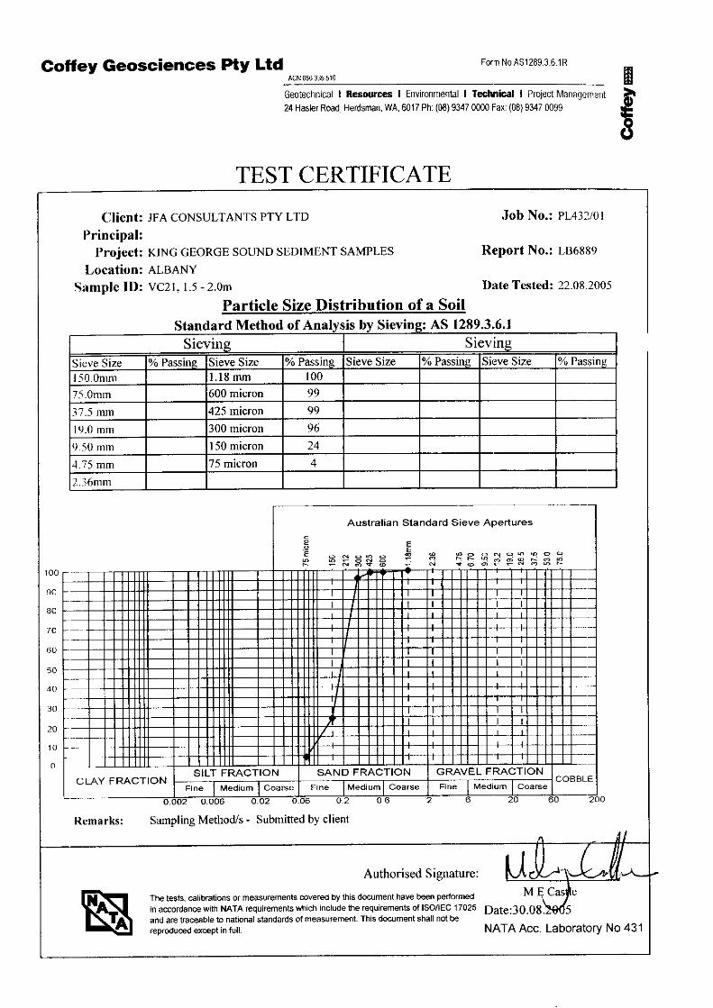
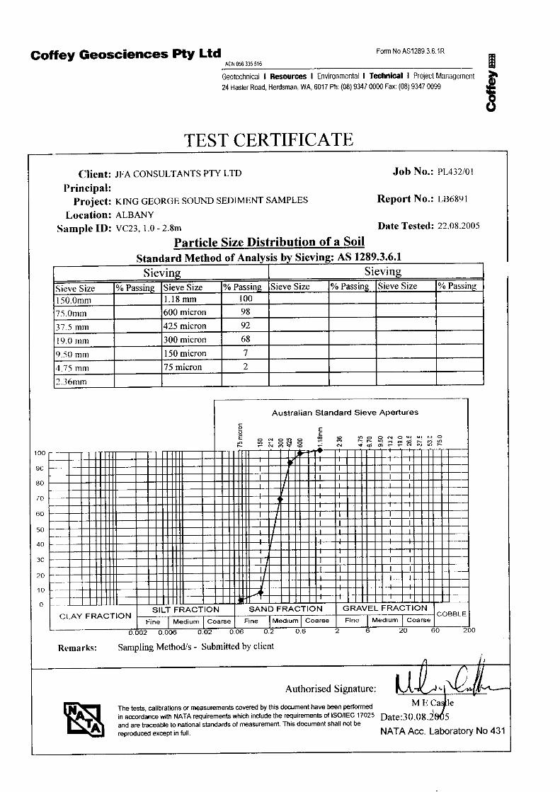
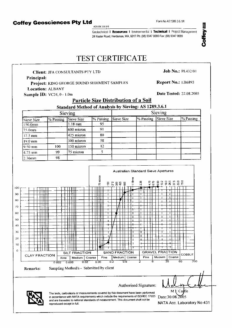
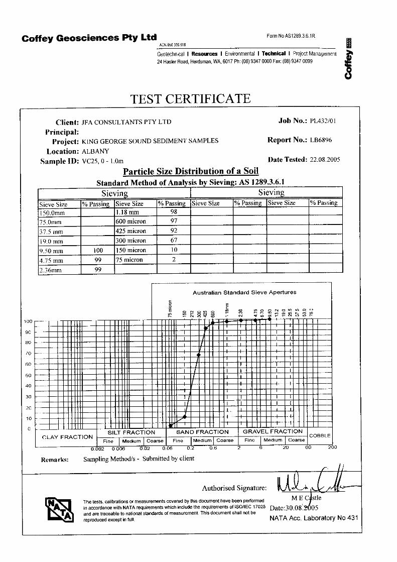
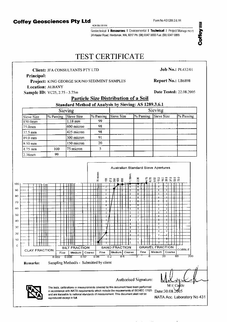
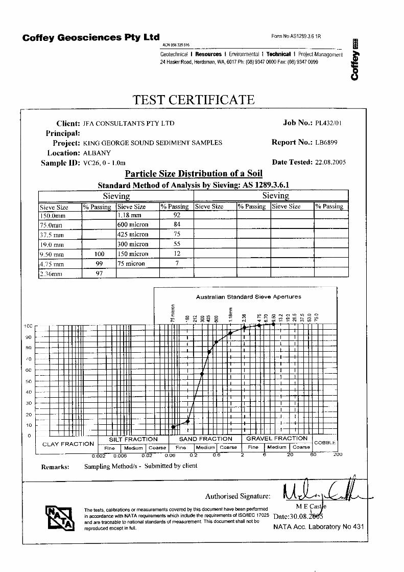
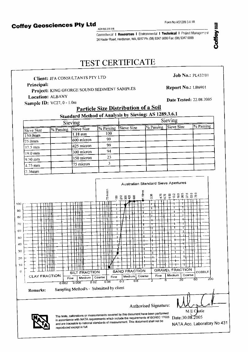
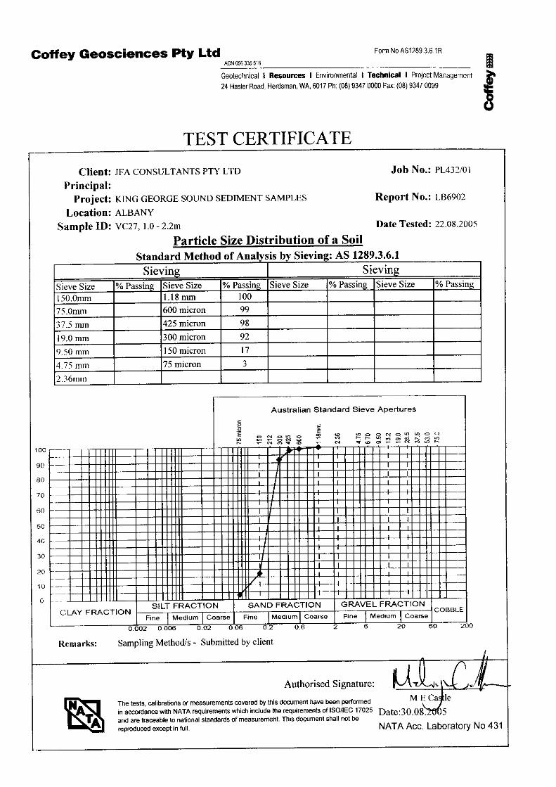
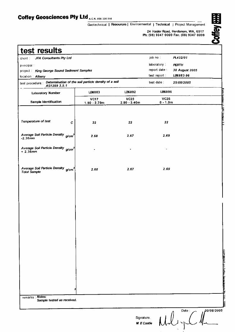
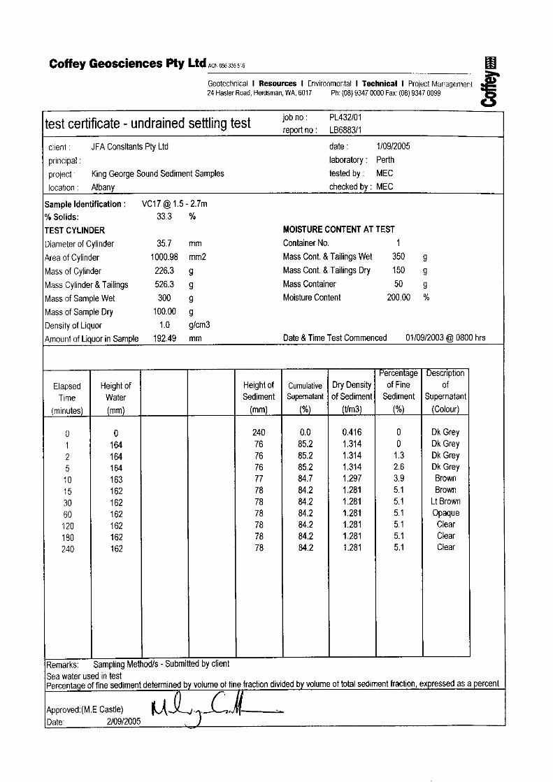
At the conclusion of the sampling program all 48 bagged samples were put in crates and transported to Perth. Dr Peter Morrison of Sinclair Knight Merz, who is responsible for the environmental investigations being carried out for the Sea Dumping Permit application to the Commonwealth Department of Environment and Heritage, contacted JFA and requested that 16 of the samples be split so that a portion could undergo chemical analysis. This was carried out and the split samples were couriered to Dr Morrison on Tuesday 24 August 2005. Following discussion with Steve Oliver of GEMS, it was determined that all 48 samples should be analysed for particle size distribution for input into the dredge plume model. Those samples that had a significant proportion of material in the clay fraction were to also have hydrometer testing carried out to determine the particle size of the clay fraction. GEMS also advised that 3 representative samples should be selected to have an Undrained Mudline Test and Density Test carried out. The purpose of the Undrained Mudline Test is to provide an indication of the settlement rate of the material. Quotes for the testing regime described above were obtained from three companies; Coffey Geosciences, Western Geotechnics and the Chemistry Centre WA. Using cost as the main selection criteria and timing as the secondary criteria, Coffey was selected as the company to carry out the testing. The samples were boxed and couriered to Coffey on Tuesday 24 August 2005. Results of the laboratory testing carried out by Coffey are included for reference in Appendix C. Note that the analysis sheets in Appendix C refer to “VC” nomenclature for the sample locations, however the numerical designations are directly transferable to the actual “SB” nomenclature used for this sampling campaign.

APPENDIX A SUMMARY SPREADSHEET

GRANGE RESOURCES SOUTHDOWN PROJECTALBANY PORT UPGRADEPROPOSED CHANNEL DREDGINGSUB-BOTTOM SAMPLING AUGUST 2005
SITE DESIGNATION CHAINAGE
DEPTH OF SEAFLOOR
[m CD]
DEPTH OF PENETRATION
[m CD]
DEPTH OF DESIGN CHANNEL
[m CD]EASTING NORTHING SAMPLE
NUMBER TOP DEPTH BOTTOM DEPTH
NOMINAL SAMPLE SIZE
VISUAL DESCRIPTION(NOT CORRELATED TO TESTING RESULTS)
IN-SITU COMMENTS(NOT CORRELATED TO TESTING RESULTS) PHOTO SKM
SAMPLE Undrained Mudline Test
Density Testing (SG)
SB02 0 -12.5 -13 -16 582916 6122045 1 0.2 0.5 SMALL sticky green clay with some shellGreen clay at 0.5mVery hard and stiff
2 0 1 GOOD fine grey sand, some shell fragments3 1.5 1.8 SMALL coarse green sand, very high shell content4 1.8 2 SMALL green clay mixed with fine sand and shell5 0 1 GOOD medium grained light grey sand with some shell content Yes6 1.5 2.7 GOOD medium to course grained sand, grey in colour with moderate to high shell content Yes
7 0 1 GOOD fine grey brown sand, minimal shell
8 1.5 1.8 SMALL fine black sand with high shell content
9 1.8 2 SMALL sticky green clay
10 0 1 GOOD medium to coarse dark grey sand, some shell fragments Yes
11 1.5 2.6 GOOD medium grained dark(black) sand some shell Yes
12 2.5 3.2 GOOD fine, dark grey sand, minimal shell content13 0 1 GOOD fine to medium sand with grey brown colour and minimal shell content Yes14 1.5 2.8 SMALL fine grey sand with high shell content Yes15 3 4.2 GOOD medium grained light grey sand with some shell content
24A 0 1 GOOD fine to medium grey sand, minimal shell
16 1 2.5 SMALL fine to medium clean grey sand
17 2.5 3.3 GOOD medium grey sand, minimal shell
18 0 1 GOOD fine sand, greenish brown colour, minimal shell Yes
19 1.5 2 GOOD fine to medium sand, yellowy brown with minimal shells. Yes
20 0 1 GOOD fine to medium grey sand
21 1.5 2.2 SMALL medium grained white sand with some shell content
22 3 3.3 SMALL fine greenish sand with some shell
23B 0 1 GOOD fine to medium dark grey sand, high shell content
Shells in upper layerdarker finer material belowgood sampling over full depth Yes
25 1.5 2.5 GOOD dark brown fine to medium sand with high shell content Yes26 2 3.5 GOOD fine brown sand, some shells
27 0 1.1 GOOD medium grain grey brown sand
28 1.5 2.7 GOOD fine to medium brown sand Yes Yes
29 0 0.8 GOOD medium to coarse white grey sand
30 1.5 2.5 GOOD fine white sand with high shell content
31 0 1 GOOD medium grained grey sand, very high shll content
32 1 2.7 SMALL fine to medium yellow brown sand, very high shell content-17.2 589106 6122825
Shelly, gritty sand upper metrebrown yellow sand below 1mBottom of longer tube broke off ~200mmSB19 5500 -16.4 -19.1
-17.2 587704 6123098
Very hard crusty layer at surfaceBroke short pole trying to retrieveshelley 0-1m, Fine sand 1.5-2mSB18 5000 -16.3 -18.8
-17.2 587130 6123277Finer material, no shellgood sampling over full probe depthSB17 4400 -15.8 -18.5
585783 6122965
Darker and shelly material in upper layerfine clean sand in the middlefine clay in lower layerOne tube unable to be removed. Cut off at sea bed
SB14
SB15 3000 -13 -16.3
SB03 750 -13.7 -15.7 -16 583631 6122271
Good sampling, clay at 1.8mGreen and stickyDifficult to remove sample
SB04 500 -13.1 -15.8 -16 583384 6122201Good samplingClay at 2.5m
SB05 1000 -13.4 -15.4 -16.5 583869 6122346
Very stiff clay at 1.8mTube stuck and unable to be removed.Shells and grit 1.5-1.8mClean sand above 1.5m
SB06 1250 -13.4 -16.6 -16.5 584102 6122413
Excellent sampling 0-3.2m, Top layer of clean grey sand1.5 to 3.2m darker finer material, some organic materialNot hard at 3.2m
Shelly sand to 0.8mSB09 -5 -9.2
-17.2 586498 6123172
583068 6122208
-17.2 585445 6122823
-17.2
SB16 3750 -14.5 -18
2500 -13.3 -15.3
Good sampling 0-3.3m. Generally clean sand in all samples.Very hard (impenetrable) at 3.3m-17.2 584577 6122561
Good sampling of darker material to 2m.Impenetrable layer at 2m - Felt like rock - not crusty
SB13 1750 -13 -16.3
PRINTED 12/09/2005 PAGE 1 OF 2
GRANGE RESOURCES SOUTHDOWN PROJECTALBANY PORT UPGRADEPROPOSED CHANNEL DREDGINGSUB-BOTTOM SAMPLING AUGUST 2005
SITE DESIGNATION CHAINAGE
DEPTH OF SEAFLOOR
[m CD]
DEPTH OF PENETRATION
[m CD]
DEPTH OF DESIGN CHANNEL
[m CD]EASTING NORTHING SAMPLE
NUMBER TOP DEPTH BOTTOM DEPTH
NOMINAL SAMPLE SIZE
VISUAL DESCRIPTION(NOT CORRELATED TO TESTING RESULTS)
IN-SITU COMMENTS(NOT CORRELATED TO TESTING RESULTS) PHOTO SKM
SAMPLE Undrained Mudline Test
Density Testing (SG)
33 0 1.5 GOOD medium grained grey sand
34 1.5 2 SMALL fine grey sand
35 0 1 GOOD medium grained grey sand with some shell content
36 1 2.8 GOOD medium grain clean grey sand
37 2.8 3.4 GOOD medium dark grey sand, minimal shell content Yes Yes38 0 1 GOOD medium to coarse grey sand, some shell fragments39 1.2 2 GOOD medium grey sand with some shell and rock fragments40 2.5 3 GOOD medium clean grey sand41 0 1 GOOD medium grained grey sand with some shell content Yes Yes Yes
42 1.5 2.5 GOOD medium grey sand with some shells Yes
43 2.75 3.75 GOOD mediumgrained grey sand, minimal shells
44 0 1 GOOD medium to coarse grey sand with some shell fragments Yes
45 1.5 2.3 GOOD medium white clean sand Yes46 0 1 GOOD fine to medium grey sand Yes47 1 2.2 GOOD fine to medium grey sand Yes48 2.2 3.2 GOOD medium grain grey sand, some shell
16-17.2 585079 6122703
Mainly grey sand to 3.3mMore shell in lower 1mRefused on hard layer
-18 590603 6120373
Upper meter 'shelly & gritty'1.5 to 2.3 fine and cleanhard layer at 2.3m
-18
SB27 2250 -13 -16.2
SB26 9000 -18.1 -20.4
588816 6122138
No crusty layer.good coring all the way down.no 'crunching'.SB25 6500 -11.8 -15.55
-18 589517 6121424
Three samples to 3.3mclean grey sand all the way downhard layer at 3.3mSB24 7500 -12.4 -15.4
-18 589139 6121762
Probes going in approximately 1mThen able to jet down but unable to retrieve probesTeam successfully removed polesReasonable material found in probesSB23 7000 -11.9 -15.3
-18 590243 6120720
Mainly sand bottomSome weed patchesSome limestone rocks on seabedProbe penetration OK to 1.5m - then hard layerAble to jet thru with some effort down to 3.0m and could have gone deeperSB21 8500 -15.8 -17.8
PRINTED 12/09/2005 PAGE 2 OF 2

APPENDIX B DRAWINGS

APPENDIX C LABORATORY TESTING RESULTS (COFFEY GEOSCIENCES)