Embed Size (px)
Citation preview
OSIPOSIPOSIP Jeff Lovin, CP Jeff Lovin, CP Vice presidentVice president
Woolpert, Inc., ContractorWoolpert, Inc., ContractorThe Ohio Statewide Imagery ProgramThe Ohio Statewide Imagery
Ohio
Statewide
Imagery
Program
Program
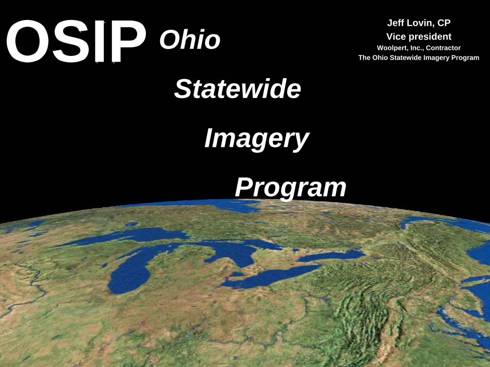
OSIP Program SummaryOSIP Program SummaryBase ProjectStatewide 1”=200’ scale color digital Orthophotography at 1-foot pixel resolution.Statewide 1”=1,000’ scale color Infrared Orthophotography at 3-foot pixel resolutionStatewide DEM derived from LiDARMetadata (FGDC)Northern Tier - 2006 Southern Tier – 2007
Buy-up Options1”=100’ scale color digital orthophotography at 0.5-foot pixel resolutionDTM and 5-foot and/or 2-foot contouring
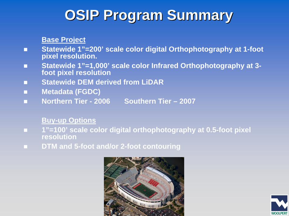
Program Delivery ScheduleProgram Delivery ScheduleImagery and DEM data will be captured and delivered in two phases. The northern portion of the state will be flown in 2006 with delivery to the state by December 31, 2006, and the southern portion flown in 2007 will be delivered to the state by December 31, 2007. Data will be available soon after the state has reviewed and approved all products.
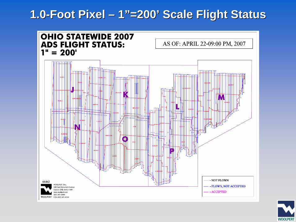
1.01.0--Foot Pixel Foot Pixel –– 1”=200’ Scale Flight Status1”=200’ Scale Flight Status
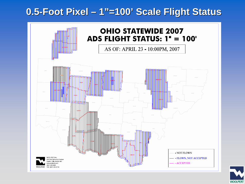
0.50.5--Foot Pixel Foot Pixel –– 1”=100’ Scale Flight Status1”=100’ Scale Flight Status
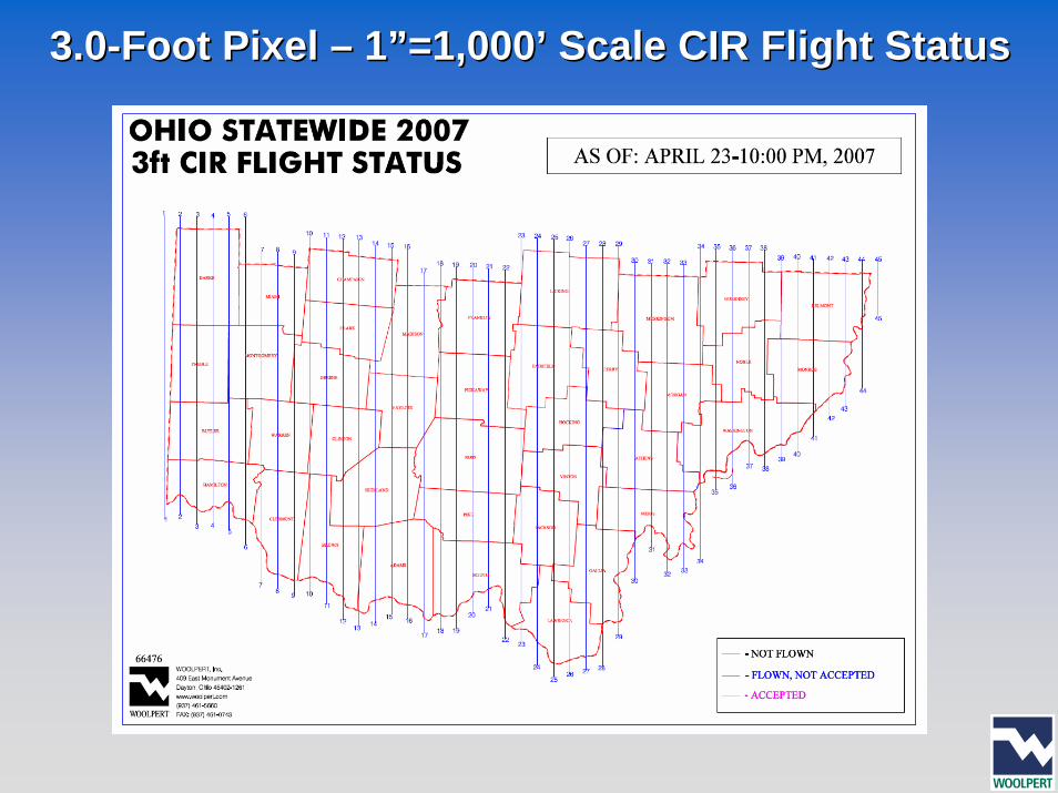
3.03.0--Foot Pixel Foot Pixel –– 1”=1,000’ Scale CIR Flight Status1”=1,000’ Scale CIR Flight Status
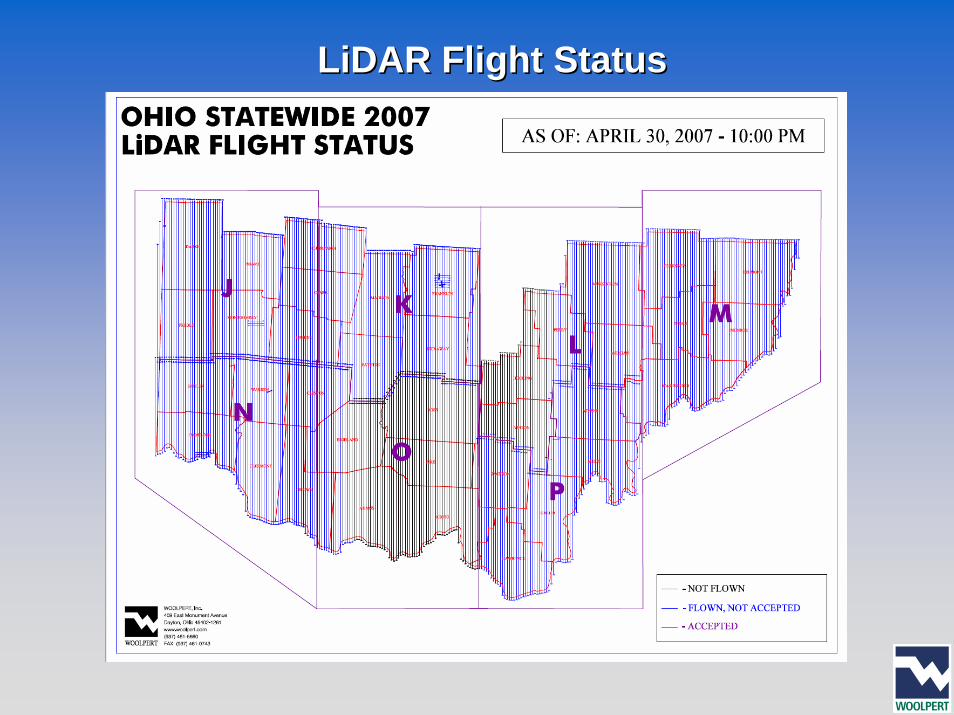
LiDAR Flight StatusLiDAR Flight Status
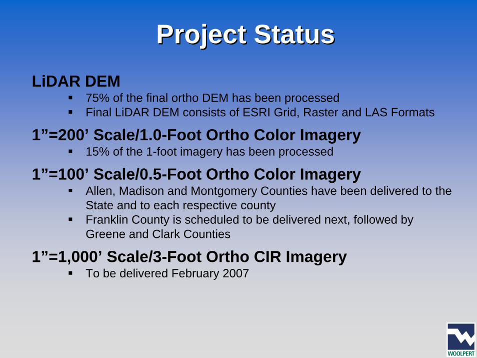
Project StatusProject StatusLiDAR DEM
75% of the final ortho DEM has been processedFinal LiDAR DEM consists of ESRI Grid, Raster and LAS Formats
1”=200’ Scale/1.0-Foot Ortho Color Imagery15% of the 1-foot imagery has been processed
1”=100’ Scale/0.5-Foot Ortho Color ImageryAllen, Madison and Montgomery Counties have been delivered to the State and to each respective countyFranklin County is scheduled to be delivered next, followed by Greene and Clark Counties
1”=1,000’ Scale/3-Foot Ortho CIR ImageryTo be delivered February 2007
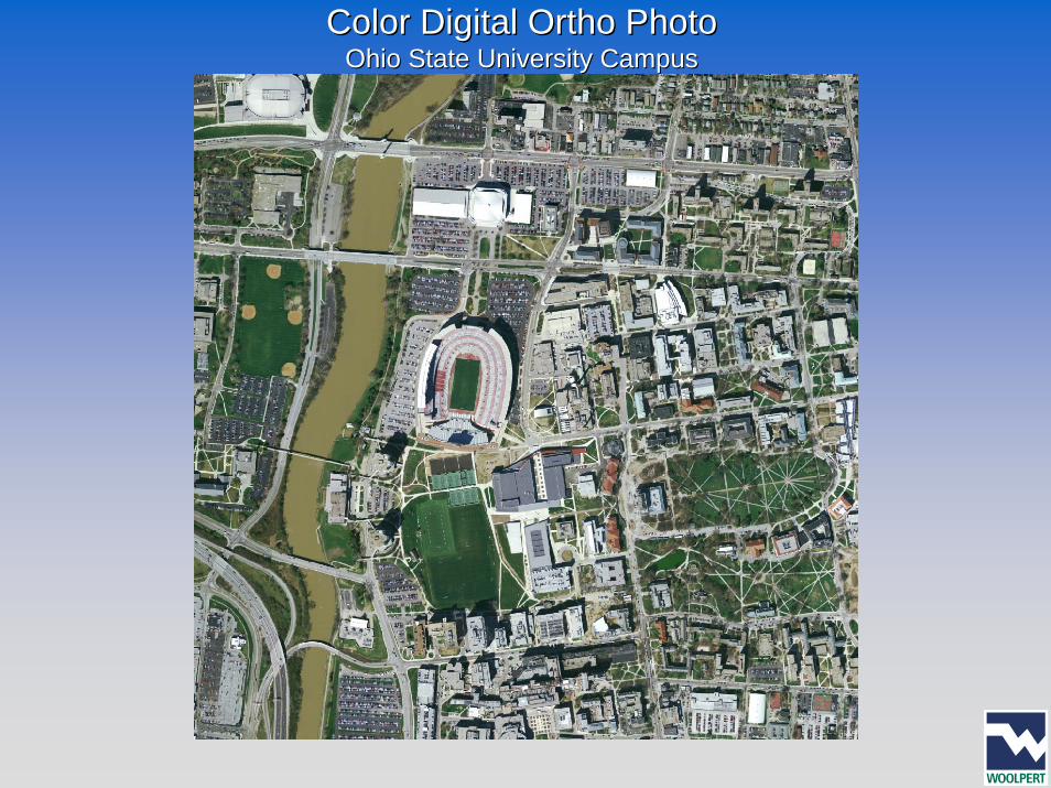
Color Digital Ortho PhotoColor Digital Ortho PhotoOhio State University CampusOhio State University Campus
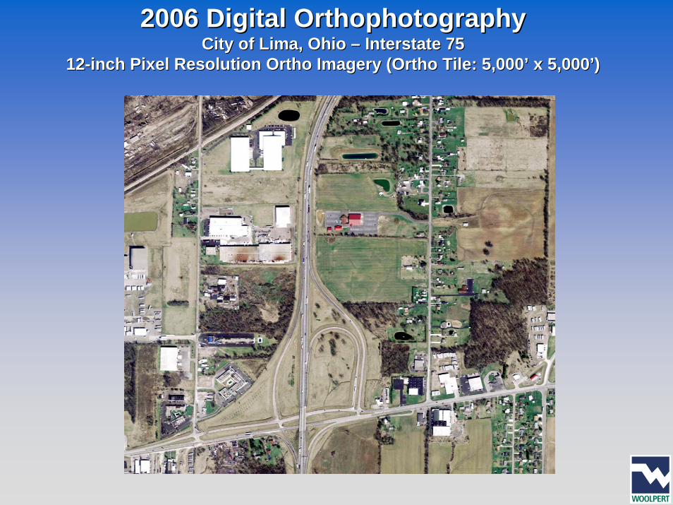
2006 Digital 2006 Digital OrthophotographyOrthophotographyCity of Lima, Ohio City of Lima, Ohio –– Interstate 75Interstate 75
1212--inch Pixel Resolution Ortho Imagery (Ortho Tile: 5,000’ x 5,000’inch Pixel Resolution Ortho Imagery (Ortho Tile: 5,000’ x 5,000’))
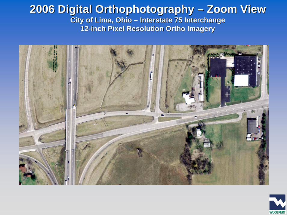
2006 Digital 2006 Digital OrthophotographyOrthophotography –– Zoom ViewZoom ViewCity of Lima, Ohio City of Lima, Ohio –– Interstate 75 InterchangeInterstate 75 Interchange
1212--inch Pixel Resolution Ortho Imageryinch Pixel Resolution Ortho Imagery
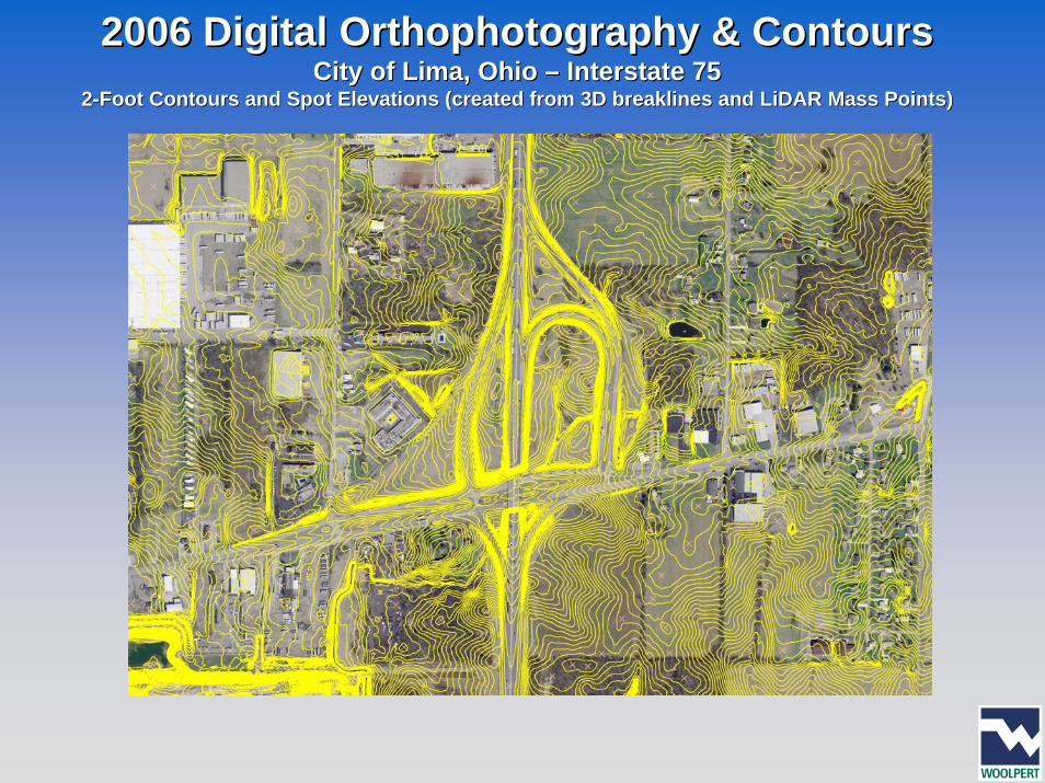
2006 Digital 2006 Digital OrthophotographyOrthophotography & Contours& ContoursCity of Lima, Ohio City of Lima, Ohio –– Interstate 75Interstate 75
22--Foot Contours and Spot Elevations (created from 3D Foot Contours and Spot Elevations (created from 3D breaklinesbreaklines and and LiDARLiDAR Mass Points)Mass Points)
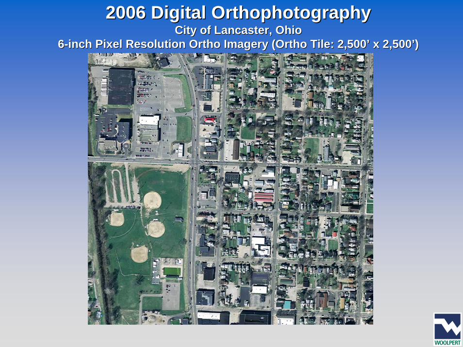
2006 Digital 2006 Digital OrthophotographyOrthophotographyCity of Lancaster, OhioCity of Lancaster, Ohio
66--inch Pixel Resolution Ortho Imagery (Ortho Tile: 2,500’ x 2,500’inch Pixel Resolution Ortho Imagery (Ortho Tile: 2,500’ x 2,500’))
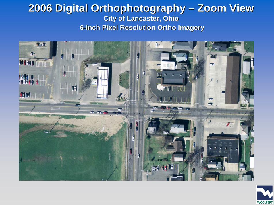
2006 Digital 2006 Digital OrthophotographyOrthophotography –– Zoom ViewZoom ViewCity of Lancaster, OhioCity of Lancaster, Ohio
66--inch Pixel Resolution Ortho Imageryinch Pixel Resolution Ortho Imagery
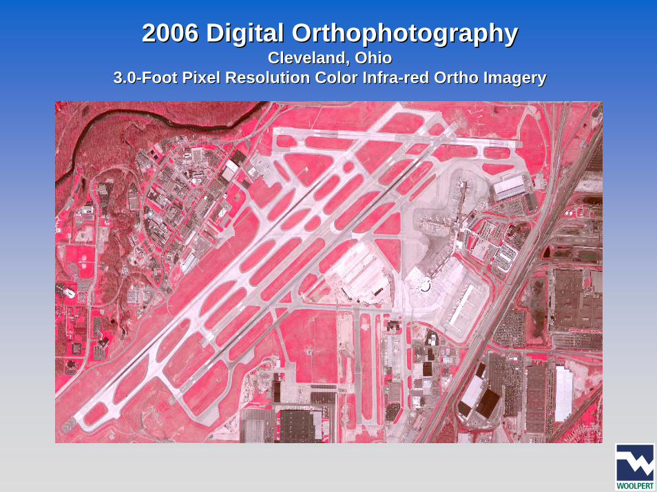
2006 Digital 2006 Digital OrthophotographyOrthophotographyCleveland, Ohio Cleveland, Ohio
3.03.0--Foot Pixel Resolution Color InfraFoot Pixel Resolution Color Infra--red Ortho Imageryred Ortho Imagery
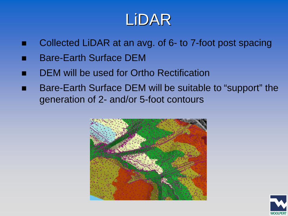
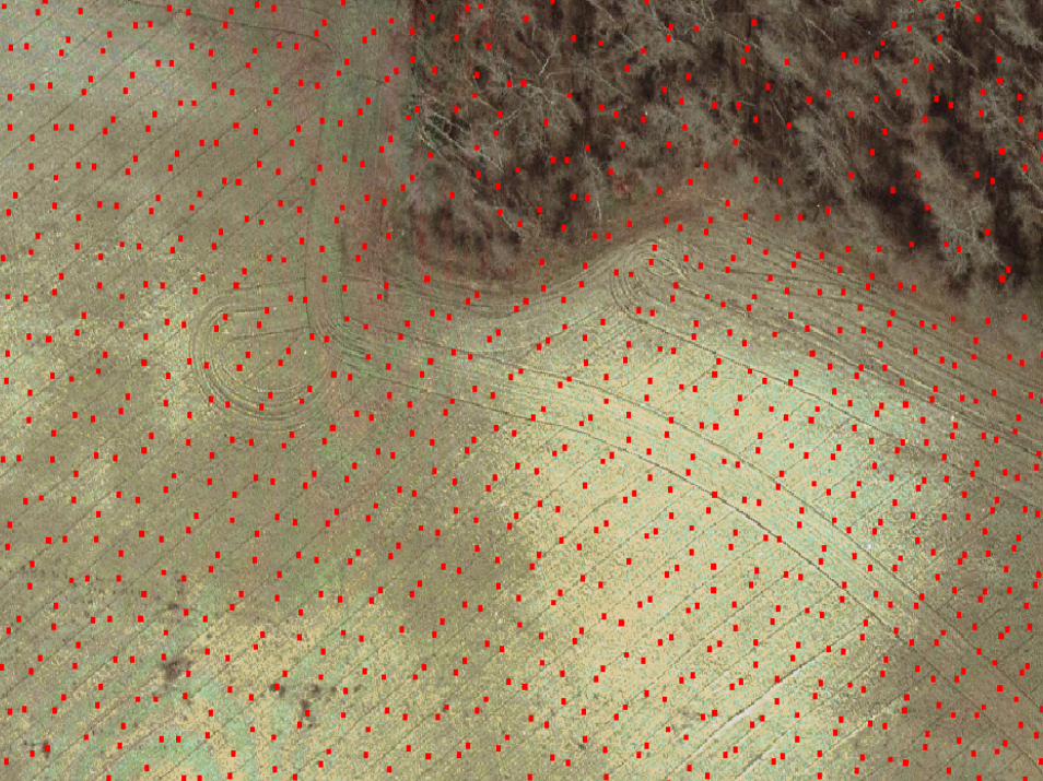
LiDARLiDARCollected LiDAR at an avg. of 6- to 7-foot post spacingBare-Earth Surface DEMDEM will be used for Ortho RectificationBare-Earth Surface DEM will be suitable to “support” the generation of 2- and/or 5-foot contours
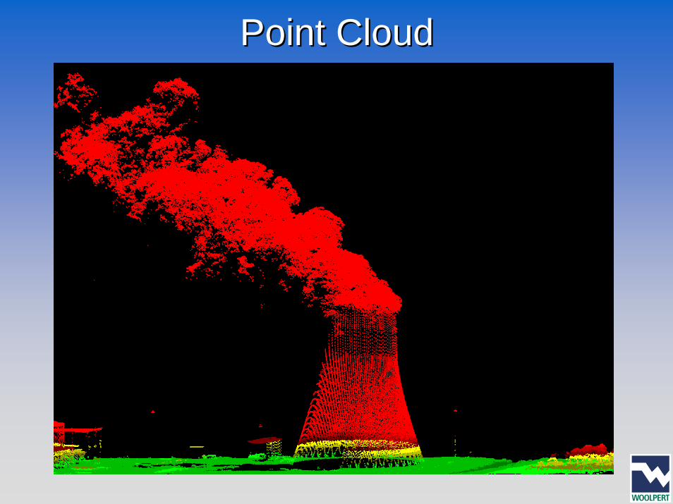
Point CloudPoint Cloud
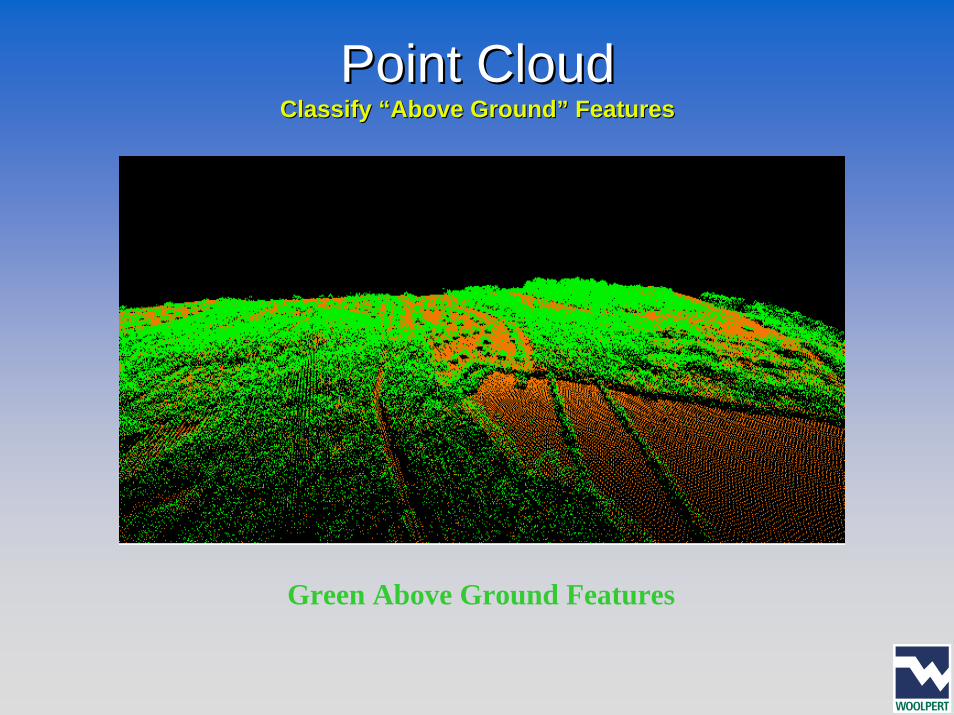
Point CloudPoint CloudClassify “Above Ground” FeaturesClassify “Above Ground” Features
Green Above Ground Features
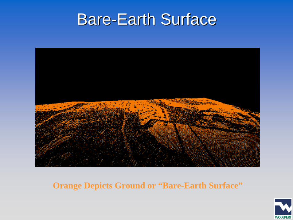
BareBare--Earth SurfaceEarth Surface
Orange Depicts Ground or “Bare-Earth Surface”
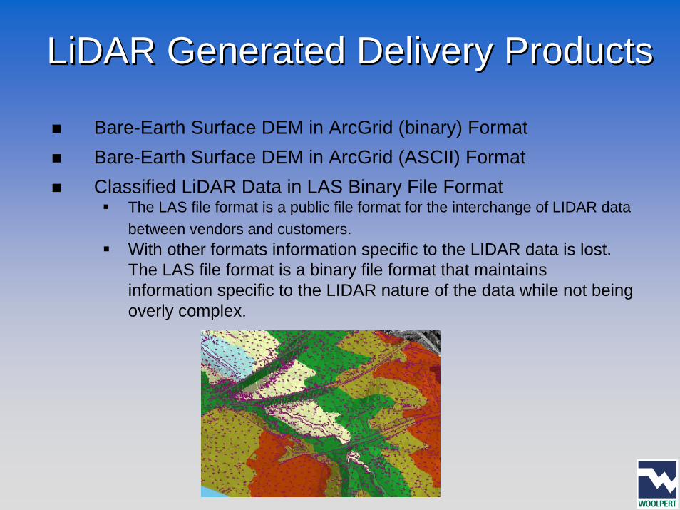
LiDAR Generated Delivery ProductsLiDAR Generated Delivery Products
Bare-Earth Surface DEM in ArcGrid (binary) FormatBare-Earth Surface DEM in ArcGrid (ASCII) FormatClassified LiDAR Data in LAS Binary File Format
The LAS file format is a public file format for the interchange of LIDAR data between vendors and customers.With other formats information specific to the LIDAR data is lost. The LAS file format is a binary file format that maintains information specific to the LIDAR nature of the data while not being overly complex.
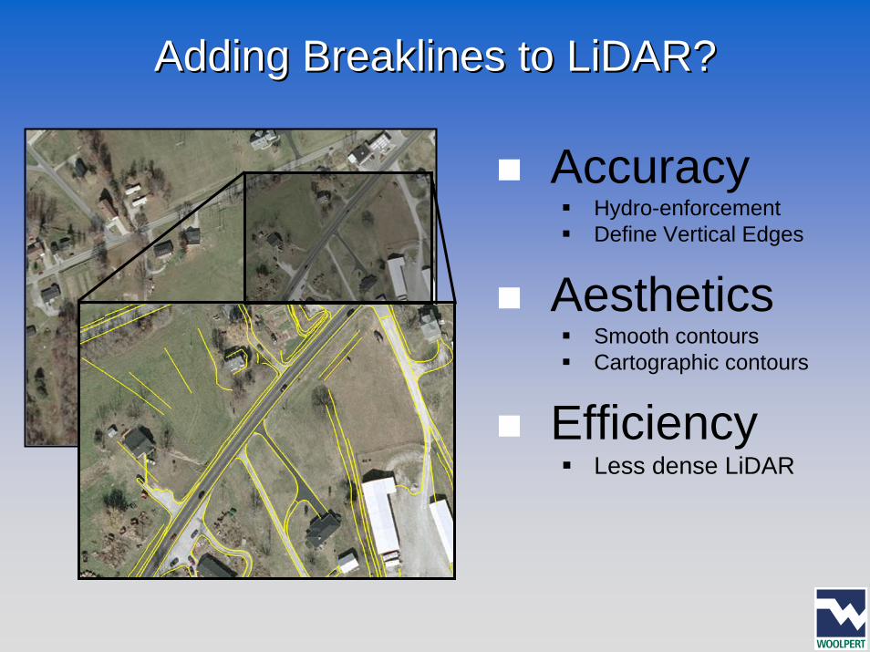
Adding Breaklines to LiDAR?Adding Breaklines to LiDAR?
AccuracyHydro-enforcementDefine Vertical Edges
AestheticsSmooth contoursCartographic contours
EfficiencyLess dense LiDAR
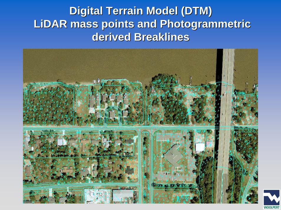
Digital Terrain Model (DTM) Digital Terrain Model (DTM) LiDAR mass points and Photogrammetric LiDAR mass points and Photogrammetric
derived Breaklinesderived Breaklines
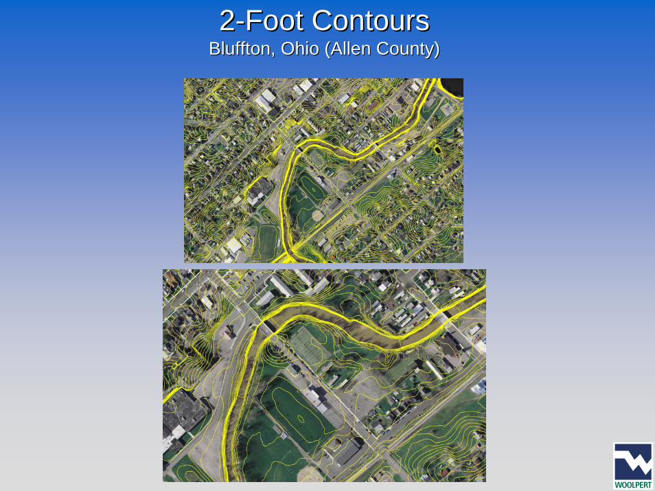
22--Foot ContoursFoot ContoursBluffton, Ohio (Allen County)Bluffton, Ohio (Allen County)
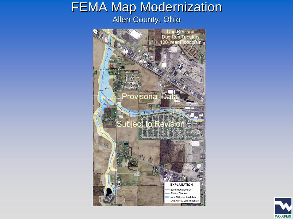
FEMA Map ModernizationFEMA Map ModernizationAllen County, OhioAllen County, Ohio
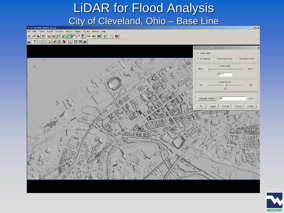
LiDARLiDAR for Flood Analysisfor Flood AnalysisCity of Cleveland, Ohio City of Cleveland, Ohio –– Base LineBase Line
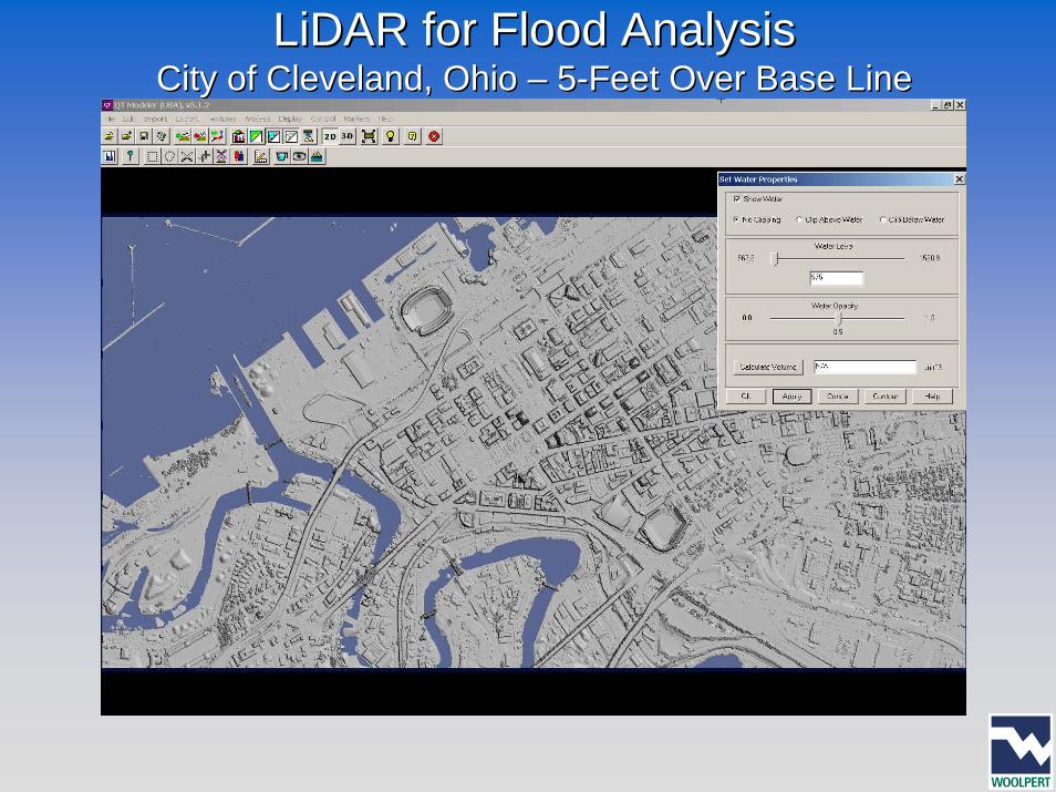
LiDARLiDAR for Flood Analysisfor Flood AnalysisCity of Cleveland, Ohio City of Cleveland, Ohio –– 55--Feet Over Base LineFeet Over Base Line
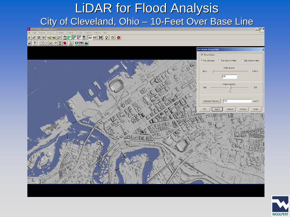
LiDARLiDAR for Flood Analysisfor Flood AnalysisCity of Cleveland, Ohio City of Cleveland, Ohio –– 1010--Feet Over Base LineFeet Over Base Line
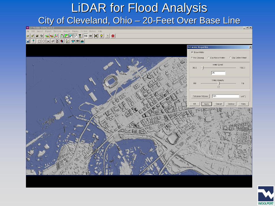
LiDARLiDAR for Flood Analysisfor Flood AnalysisCity of Cleveland, Ohio City of Cleveland, Ohio –– 2020--Feet Over Base LineFeet Over Base Line
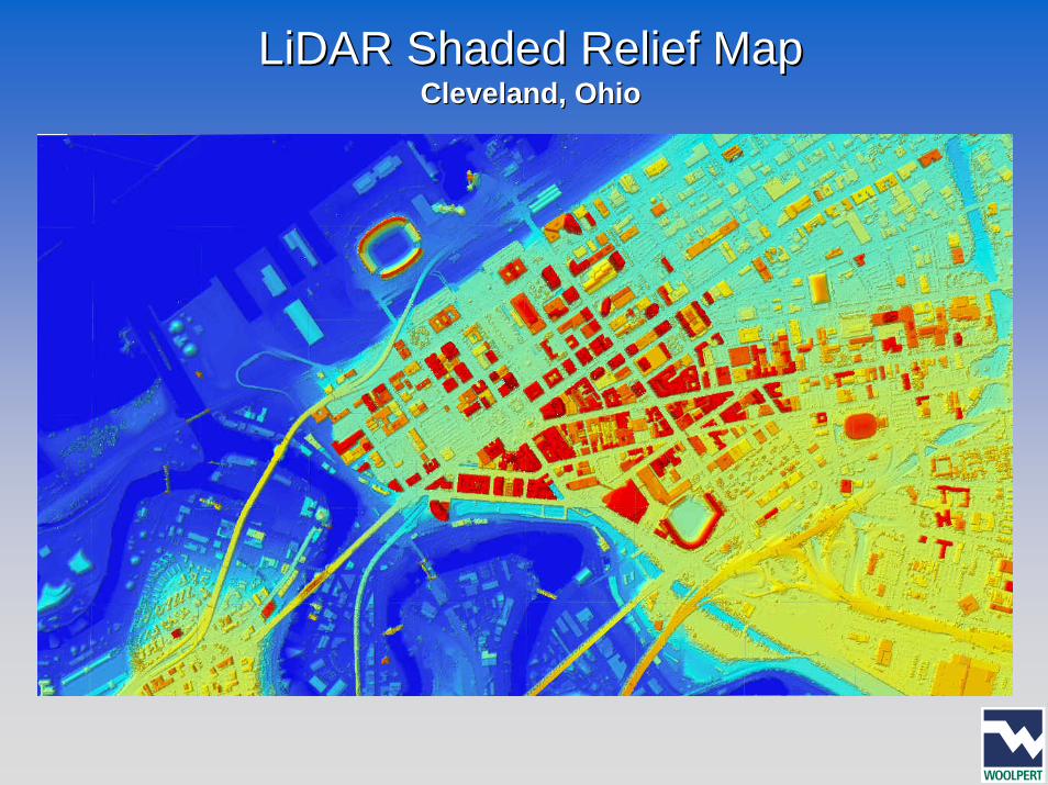
LiDARLiDAR Shaded Relief MapShaded Relief MapCleveland, OhioCleveland, Ohio
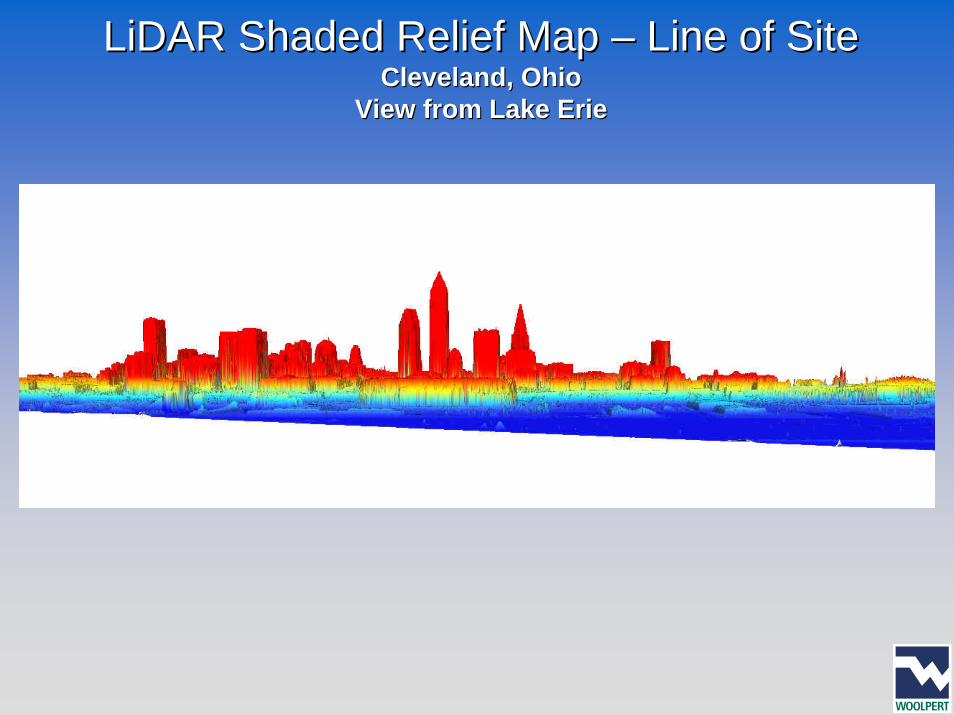
LiDARLiDAR Shaded Relief Map Shaded Relief Map –– Line of SiteLine of SiteCleveland, OhioCleveland, Ohio
View from Lake ErieView from Lake Erie
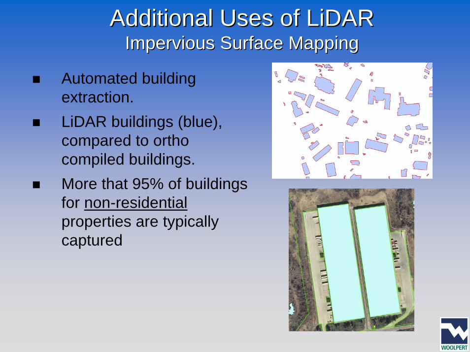
Additional Uses of Additional Uses of LiDARLiDARImpervious Surface MappingImpervious Surface Mapping
Automated building extraction. LiDAR buildings (blue), compared to ortho compiled buildings.More that 95% of buildings for non-residentialproperties are typically captured
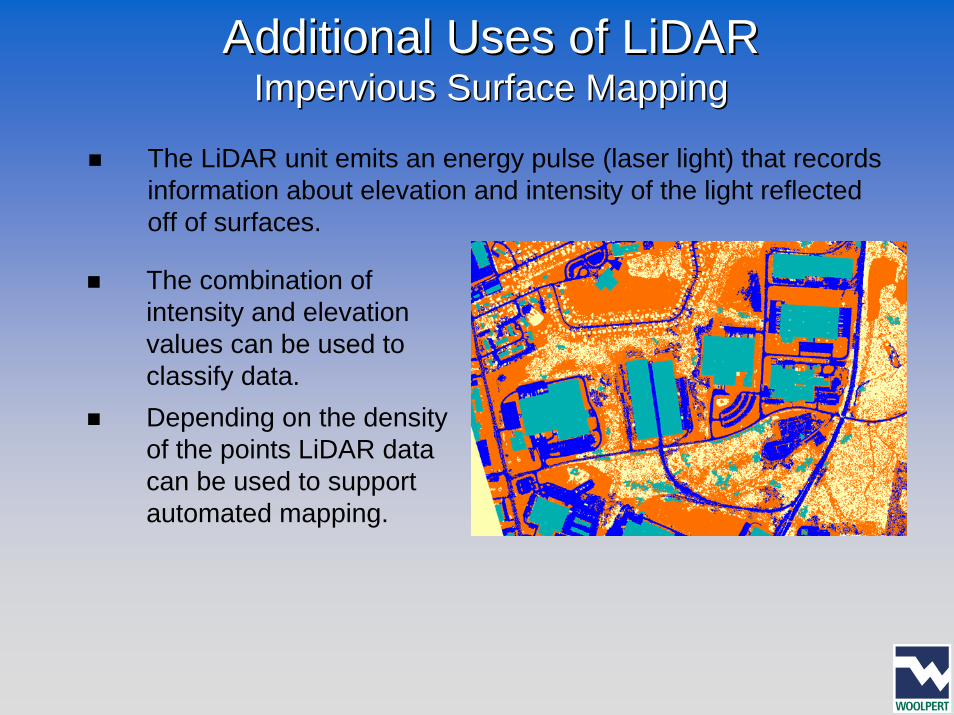
Additional Uses of Additional Uses of LiDARLiDARImpervious Surface MappingImpervious Surface Mapping
The LiDAR unit emits an energy pulse (laser light) that records information about elevation and intensity of the light reflectedoff of surfaces.
The combination of intensity and elevation values can be used to classify data.Depending on the density of the points LiDAR data can be used to support automated mapping.
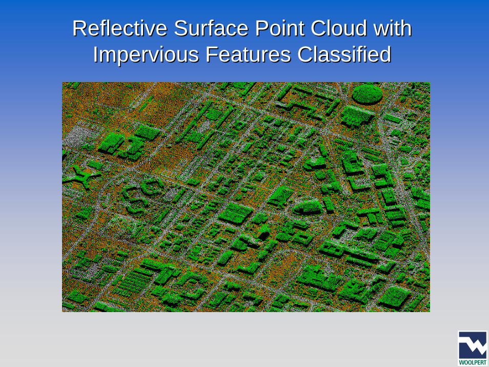
Reflective Surface Point Cloud with Reflective Surface Point Cloud with Impervious Features ClassifiedImpervious Features Classified
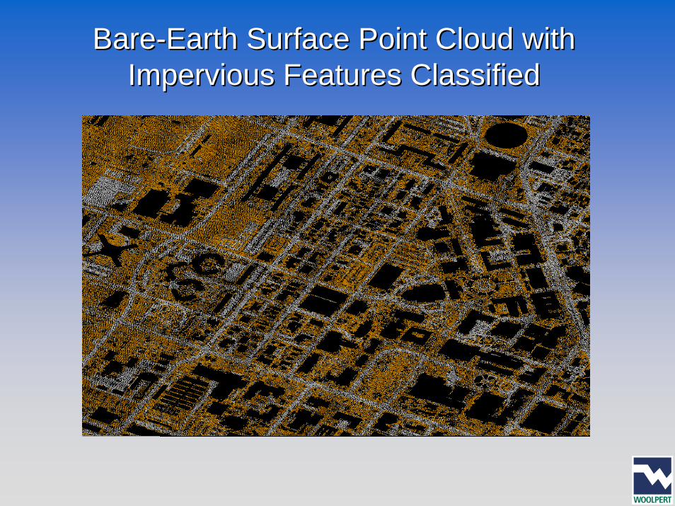
BareBare--Earth Surface Point Cloud with Earth Surface Point Cloud with Impervious Features ClassifiedImpervious Features Classified
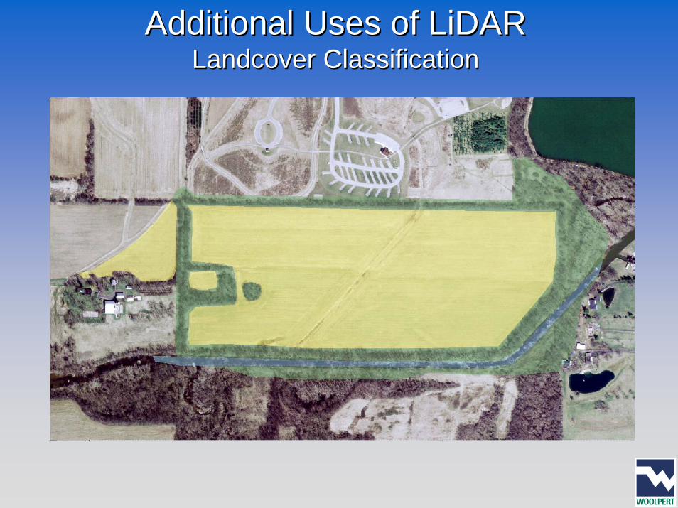
Additional Uses of Additional Uses of LiDARLiDARLandcoverLandcover ClassificationClassification
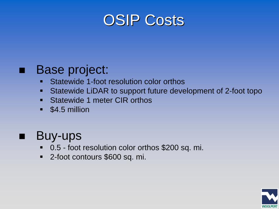
OSIP CostsOSIP Costs
Base project: Statewide 1-foot resolution color orthosStatewide LiDAR to support future development of 2-foot topoStatewide 1 meter CIR orthos$4.5 million
Buy-ups0.5 - foot resolution color orthos $200 sq. mi.2-foot contours $600 sq. mi.