Embed Size (px)
Citation preview
ISBN 978-0-626-20745-8 SANS 719:2008Edition 3.1
Any reference to SABS 719 is deemedto be a reference to this standard
(Government Notice No. 1373 of 8 November 2002)
SOUTH AFRICAN NATIONAL STANDARD
Electric welded low carbon steel pipes for aqueous fluids (large bore)
Published by Standards South Africa 1 dr lategan road groenkloof private bag x191 pretoria 0001 tel: 012 428 7911 fax: 012 344 1568 international code + 27 12 www.stansa.co.za © Standards South Africa
SANS 719:2008 Edition 3.1 Table of changes
Change No. Date Scope Amdt 1 2008 Amended to change the designation of SABS standards to SANS
standards and to update the definition of "acceptable". Acknowledgement Standards South Africa wishes to acknowledge the valuable assistance derived from publications of the following organizations: American Petroleum Institute British Standards Institute Deutscher Normenausschuss Foreword This South African standard was approved by National Committee StanSA SC 5120.12D, Water and sanitation – Equipment and systems – Copper pipes and steel pipes and fittings, in accordance with procedures of Standards South Africa, in compliance with annex 3 of the WTO/TBT agreement. This document was published in February 2008. This document supersedes SABS 719:2002 (edition 3). A vertical line in the margin shows where the text has been technically modified by amendment No. 1. Annex A forms an integral part of this document. Annex B is for information only.
www.bzfxw.com
SANS 719:2008 Edition 3.1
1
Contents
Page Acknowledgement Foreword 1 Scope ............................................................................................................................... 3 2 Normative references ....................................................................................................... 3 3 Definitions ........................................................................................................................ 3 4 Material requirements ...................................................................................................... 4 5 General requirements ...................................................................................................... 5 6 Inspection and methods of test ........................................................................................ 10 6.1 Inspection ................................................................................................................ 10 6.2 Destructive tests ...................................................................................................... 11 6.3 Hydraulic test .......................................................................................................... 11 6.4 Coatings and linings ................................................................................................ 11 7 Marking ............................................................................................................................ 11 Figures 1 - 4 ......................................................................................................................... 12-13 Annex A (normative) Notes to purchasers ....................................................................... 14 Annex B (informative) Quality verification of electric welded low carbon steel pipes ........ 15 Bibliography ........................................................................................................................ 15
www.bzfxw.com
SANS 719:2008 Edition 3.1
2
This page is intentionally left blank
www.bzfxw.com
SANS 719:2008 Edition 3.1
3
Electric welded low carbon steel pipes for aqueous fluids (large bore) 1 Scope This standard covers three grades of carbon steel pipes of size 219,1 mm to 2 230 mm used in the conveyance of water and other aqueous fluids. 2 Normative references The following standards contain provisions which, through reference in this text, constitute provisions of this standard. All standards are subject to revision, and since any reference to a standard is deemed to be a reference to the latest edition of that standard, parties to agreements based on this standard are encouraged to take steps to ensure the use of the most recent editions of the standards indicated below. Information on currently valid national and international standards can be obtained from Standards South Africa. SANS 32/EN 10240, Internal and/or external protective coatings for steel tubes – Specification for hot dip galvanized coatings applied in automatic plants. SANS 121/ISO 1461, Hot-dip galvanized coatings on fabricated iron and steel articles – Specifications and test methods. SANS 1178 (SABS 1178), The production of lined and coated steel pipes using bitumen or coal tar enamel. SANS 1217 (SABS 1217), The production of painted and powder-coated steel pipes. SANS 6892/ISO 6892, Metallic materials – Tensile testing at ambient temperature. SANS 10044-1, Welding – Part 1: Glossary of terms. 3 Definitions For the purposes of this specification, the definitions given in SANS 10044-1 and the following definitions shall apply: 3.1 acceptable acceptable to the authority administering this standard, or to the parties concluding the purchase contract, as relevant Amdt 1 3.2 agreed agreed upon in writing between the manufacturer and the purchaser
www.bzfxw.com
SANS 719:2008 Edition 3.1
4
3.3 pipe straight cylinder of uniform nominal bore and having square-cut (plain or prepared) ends 3.4 random length normal manufacturing length that is within a limited percentage (see 5.1.1) of the average length required by the purchaser 3.5 size (of a pipe) outside diameter of a pipe 4 Material requirements 4.1 Steel plate and strip The steel plates or strip used for the manufacture of the pipes shall be free from seams, cracks, laminations (not more than level 2) and other injurious defects. 4.2 Chemical composition The chemical composition (ladle analysis) of the steel shall comply with the requirements given in table 1 appropriate to the grade of pipe specified by the purchaser, unless otherwise agreed upon between the purchaser and the manufacturer (see 4.3).
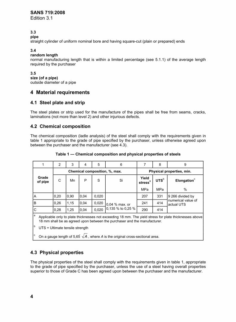
Table 1 — Chemical composition and physical properties of steels
1 2 3 4 5 6 7 8 9
Chemical composition, %, max. Physical properties, min.
C Mn P S Si Yield stressa UTSb Elongationc
Grade of pipe
MPa MPa %
A 0,20 0,90 0,04 0,020 207 331
B 0,26 1,15 0,04 0,020 241 414
C 0,28 1,25 0,04 0,020
0,04 % max. or 0,135 % to 0,25 % 290 414
9 266 divided by numerical value of actual UTS
a Applicable only to plate thicknesses not exceeding 18 mm. The yield stress for plate thicknesses above 18 mm shall be as agreed upon between the purchaser and the manufacturer. b UTS = Ultimate tensile strength
c On a gauge length of 5,65 A , where A is the original cross-sectional area.
4.3 Physical properties The physical properties of the steel shall comply with the requirements given in table 1, appropriate to the grade of pipe specified by the purchaser, unless the use of a steel having overall properties superior to those of Grade C has been agreed upon between the purchaser and the manufacturer.
www.bzfxw.com
SANS 719:2008 Edition 3.1
5
4.4 Certification When so required by the purchaser, the manufacturer shall make available to the purchaser steel-makers' certificates covering all steel used in the manufacture of the pipes. These certificates shall include the process of manufacture, the chemical analysis and the physical properties of the steel, except that, at the option of the pipe manufacturer, the physical properties of the steel may be determined on specimens taken from finished pipe. 5 General requirements 5.1 Dimensional requirements 5.1.1 Pipe length 5.1.1.1 General The total pipe length required shall be as specified by the purchaser. This total length shall comprise random lengths of pipe or exact lengths of pipe as specified by the purchaser. 5.1.1.2 Random lengths Random lengths shall be between 4,5 m and 13,5 m long. The average length shall be as specified by the purchaser. Not more than 10 % of the random lengths of pipe shall be shorter than 75 % of the average length. 5.1.1.3 Exact lengths The exact length of pipes shall be a) as specified by the purchaser, subject to a tolerance as specified, or otherwise b) off-mill lengths subject to a tolerance of 0 mm + 50 mm. 5.1.2 Dimensions The nominal bore of a pipe shall conform to the values given in columns 1 and 2, respectively, of table 2, unless otherwise specified by the purchaser. The actual outside diameter of the pipe, when determined in accordance with 6.1.1(a) or 6.1.1(b), as relevant, shall not differ from the nominal value by more than the following tolerances: a) over the appropriate length (measured from each end of the pipe) given in column 3 or 5, as
relevant, of table 3: the corresponding tolerance given in column 2 or 4 of table 3. b) over the rest of the pipe: the appropriate tolerance given in column 2 of table 4. Any out-of-roundness (other than that caused by sag), determined in accordance with 6.1.1(b)(2), of pipes of outside diameter greater than 500 mm shall not exceed 1 % of the outside diameter (i.e. maximum ovality 2 %) or 6 mm, whichever is less. 5.1.3 Wall thickness The wall thickness of a pipe shall, subject to a tolerance of +10 % or S8 %, be one of the relevant values given in columns 3 to 6 of table 2, unless otherwise agreed upon between the manufacturer and the purchaser.
www.bzfxw.com
SANS 719:2008 Edition 3.1
6
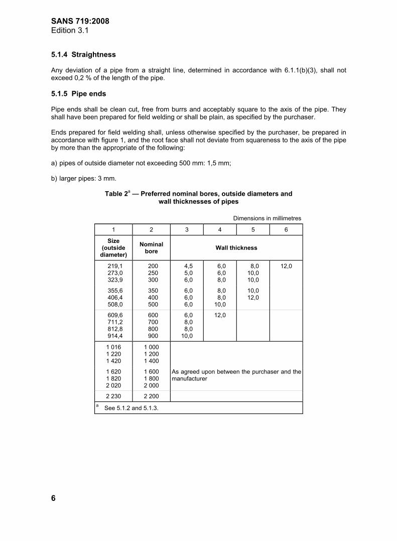
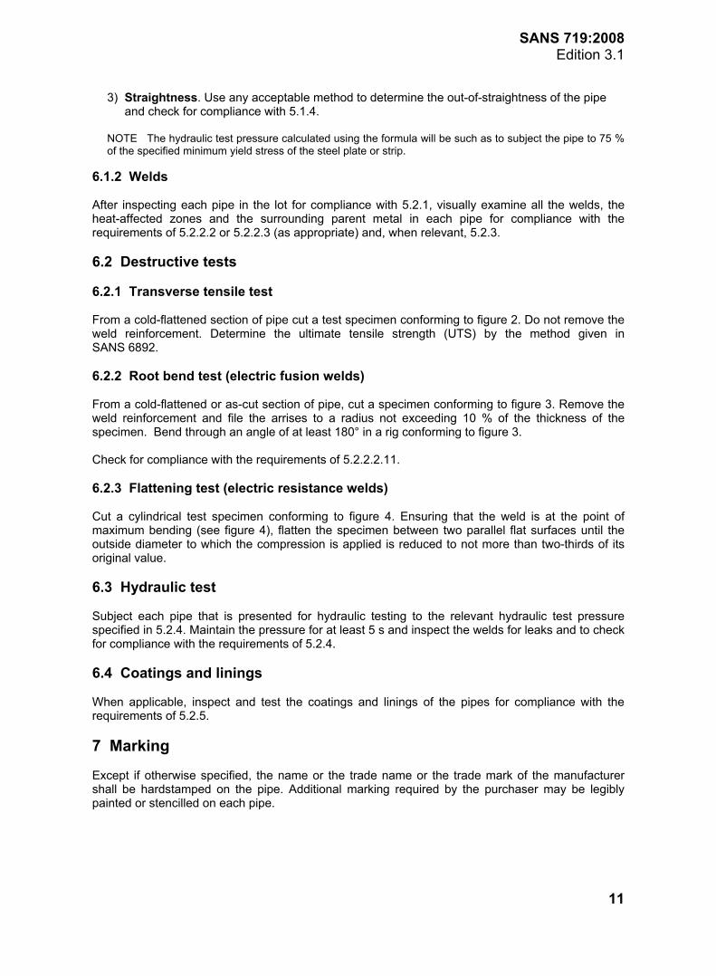
5.1.4 Straightness Any deviation of a pipe from a straight line, determined in accordance with 6.1.1(b)(3), shall not exceed 0,2 % of the length of the pipe. 5.1.5 Pipe ends Pipe ends shall be clean cut, free from burrs and acceptably square to the axis of the pipe. They shall have been prepared for field welding or shall be plain, as specified by the purchaser. Ends prepared for field welding shall, unless otherwise specified by the purchaser, be prepared in accordance with figure 1, and the root face shall not deviate from squareness to the axis of the pipe by more than the appropriate of the following: a) pipes of outside diameter not exceeding 500 mm: 1,5 mm; b) larger pipes: 3 mm.
Table 2a — Preferred nominal bores, outside diameters and wall thicknesses of pipes
Dimensions in millimetres
1 2 3 4 5 6
Size (outside
diameter) Nominal
bore Wall thickness
219,1 273,0 323,9
200 250 300
4,5 5,0 6,0
6,0 6,0 8,0
8,0 10,0 10,0
12,0
355,6 406,4 508,0
350 400 500
6,0 6,0 6,0
8,0 8,0 10,0
10,0 12,0
609,6 711,2 812,8 914,4
600 700 800 900
6,0 8,0 8,0 10,0
12,0
1 016 1 220 1 420
1 000 1 200 1 400
1 620 1 820 2 020
1 600 1 800 2 000
As agreed upon between the purchaser and the manufacturer
2 230 2 200 a See 5.1.2 and 5.1.3.
www.bzfxw.com
SANS 719:2008 Edition 3.1
7
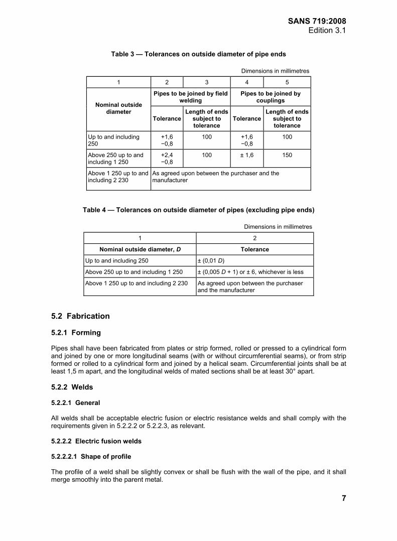
Table 3 — Tolerances on outside diameter of pipe ends
Dimensions in millimetres
1 2 3 4 5
Pipes to be joined by field welding
Pipes to be joined by couplings
Nominal outside diameter
ToleranceLength of ends
subject to tolerance
ToleranceLength of ends
subject to tolerance
Up to and including 250
+1,6 −0,8
100 +1,6 −0,8
100
Above 250 up to and including 1 250
+2,4 −0,8
100 ± 1,6 150
Above 1 250 up to and including 2 230
As agreed upon between the purchaser and the manufacturer
Table 4 — Tolerances on outside diameter of pipes (excluding pipe ends)
Dimensions in millimetres
1 2
Nominal outside diameter, D Tolerance
Up to and including 250 ± (0,01 D)
Above 250 up to and including 1 250 ± (0,005 D + 1) or ± 6, whichever is less
Above 1 250 up to and including 2 230 As agreed upon between the purchaser and the manufacturer
5.2 Fabrication 5.2.1 Forming Pipes shall have been fabricated from plates or strip formed, rolled or pressed to a cylindrical form and joined by one or more longitudinal seams (with or without circumferential seams), or from strip formed or rolled to a cylindrical form and joined by a helical seam. Circumferential joints shall be at least 1,5 m apart, and the longitudinal welds of mated sections shall be at least 30° apart. 5.2.2 Welds 5.2.2.1 General All welds shall be acceptable electric fusion or electric resistance welds and shall comply with the requirements given in 5.2.2.2 or 5.2.2.3, as relevant. 5.2.2.2 Electric fusion welds 5.2.2.2.1 Shape of profile The profile of a weld shall be slightly convex or shall be flush with the wall of the pipe, and it shall merge smoothly into the parent metal.
www.bzfxw.com
SANS 719:2008 Edition 3.1
8
5.2.2.2.2 Uniformity of appearance The face of a weld shall be substantially uniform in appearance throughout its length. 5.2.2.2.3 Overlap There shall be no overlap at the toes of a weld. 5.2.2.2.4 Undercut Welds shall be substantially free from undercut and, if present: a) the depth of the undercut shall not exceed 12,5 % of the nominal wall thickness or 1 mm,
whichever is less; and b) the aggregate length of undercut in any 1 m length of weld shall not exceed 50 mm. 5.2.2.2.5 Penetration bead In butt welds made from one side only, a slight penetration bead should be present, but absence of a penetration bead shall be permitted in isolated places, provided that there is complete root fusion. 5.2.2.2.6 Root groove In butt welds made from one side only, a root groove may be present, provided that it has a rounded outline and does not penetrate below the level of the adjacent surfaces of the parent plate. 5.2.2.2.7 Weld reinforcements The heights of outer and inner weld reinforcements shall not exceed 3 mm in pipes of wall thickness not exceeding 10 mm, and 5 mm in pipes having thicker walls, except that when so required by the purchaser, the height of the inner weld reinforcement shall not exceed 1 mm. 5.2.2.2.8 Freedom from cracks The weld metal, the heat-affected zone and the surrounding parent metal shall be free from cracks. 5.2.2.2.9 Freedom from surface defects The weld face shall be free from porosity, cavities and trapped slag. 5.2.2.2.10 Transverse tensile strength of welded joints Test specimens, prepared and tested in accordance with 6.2.1, shall have an ultimate tensile strength equal to at least 95 % of the minimum specified for the appropriate parent plate (see table 1). 5.2.2.2.11 Resistance to bending Test specimens, prepared and tested in accordance with 6.2.2, shall, except at the arrises, show no crack (on the outer surface) of length or width greater than 3 mm.
www.bzfxw.com
SANS 719:2008 Edition 3.1
9
5.2.2.3 Electric resistance welds 5.2.2.3.1 Uniformity of appearance A weld shall be substantially uniform in appearance and shall show full fusion throughout its length. 5.2.2.3.2 Upset metal and flash The height of upset metal and flash on the outer surface shall not exceed 1 mm. This requirement shall also apply to the inner surface. Any surface indentations resultant from the removal of excess material shall be such that: a) their depth does not exceed 12,5% of the nominal wall thickness or 1 mm, whichever is less; and b) their aggregate length in any 1 m length of weld does not exceed 50 mm. 5.2.2.3.3 Freedom from cracks The joint, the heat-affected zone and the parent metal shall be free from cracks. 5.2.2.3.4 Transverse tensile strength of welded joint Test specimens, prepared and tested in accordance with 6.2.1, shall have an ultimate tensile strength equal to at least 95 % of the minimum specified for the appropriate parent plate (see table 1). 5.2.2.3.5 Resistance to flattening Test specimens, prepared and tested in accordance with 6.2.3, shall show no cracks on the outer surface. 5.2.3 Rectification of defects Welded seams and surface defects (i.e. defects which would not have caused leaks) that have been repaired by welding shall be permitted in the parent metal, provided that the welds comply with the requirements of 5.2.2.2 or 5.2.2.3, as relevant. 5.2.4 Resistance to hydraulic pressure When tested in accordance with 6.3, pipes shall be capable of withstanding, without leaking or bursting, the hydraulic test pressure calculated using the following formula, subject to a maximum of 7 MPa, unless otherwise agreed upon between the purchaser and the manufacturer:
× ×
=Y t
PD
1,5
where
P is the hydraulic test pressure, in megapascals;
Y is the minimum specified yield stress of steel plate or strip, in megapascals (see 4.3);
t is the nominal wall thickness of pipe, in millimetres;
D is the nominal outside diameter of pipe, in millimetres.
www.bzfxw.com
SANS 719:2008 Edition 3.1
10
5.2.5 Coatings and linings 5.2.5.1 General When so required by the purchaser, the pipes shall have been cleaned and coated or lined (or both), in accordance with the relevant requirements of SANS 32, SANS 121, SANS 1178 or SANS 1217, or as agreed upon between the purchaser and the manufacturer. Pipes that are intended to be galvanized shall have the inside weld seam not exceeding (0,5 + 0,5 t) mm, where t is the nominal wall thickness of pipe. 5.2.5.2 Special lining Special linings shall be as agreed upon between the manufacturer and the purchaser. 6 Inspection and methods of test 6.1 Inspection 6.1.1 Dimensions Unless otherwise specified, use any method that will provide the required accuracy to measure the dimensions of a pipe for compliance with 5.1. In the case of measurements of outside diameter and out-of-roundness, use the following rules: a) Pipes of nominal outside diameter not exceeding 500 mm. Use ring gauges to check the
ends of the pipes, and use any acceptable method to check the body. b) Pipes of nominal outside diameter greater than 500 mm 1) Outside diameter. Use a diameter tape to check the outside diameter of both the pipe ends
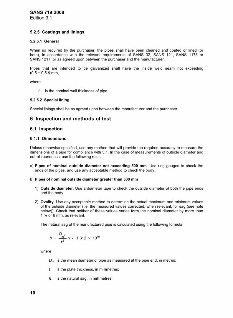
and the body. 2) Ovality. Use any acceptable method to determine the actual maximum and minimum values
of the outside diameter (i.e. the measured values corrected, when relevant, for sag (see note below)). Check that neither of these values varies form the nominal diameter by more than 1 % or 6 mm, as relevant.
The natural sag of the manufactured pipe is calculated using the following formula:
= × ×D
ht
4 10m2
n 1,312 10
where Dm is the mean diameter of pipe as measured at the pipe end, in metres; t is the plate thickness, in millimetres; h is the natural sag, in millimetres;
www.bzfxw.com
SANS 719:2008 Edition 3.1
11
3) Straightness. Use any acceptable method to determine the out-of-straightness of the pipe and check for compliance with 5.1.4.
NOTE The hydraulic test pressure calculated using the formula will be such as to subject the pipe to 75 %
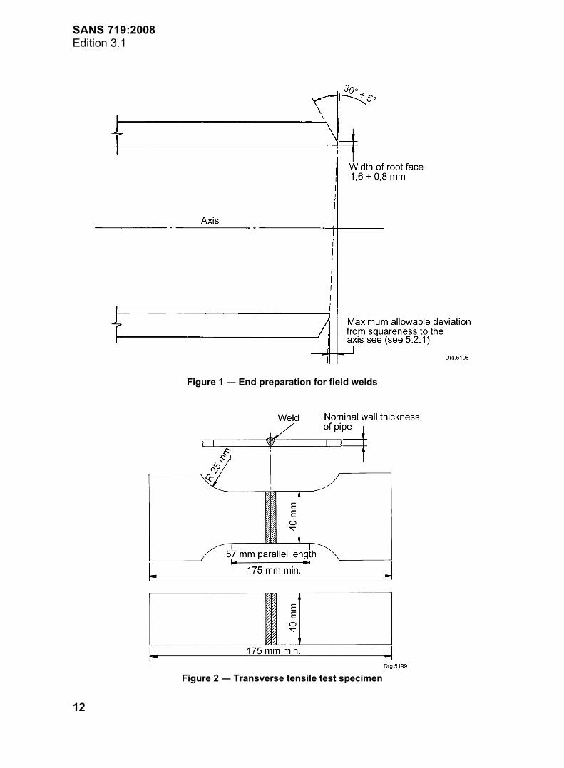
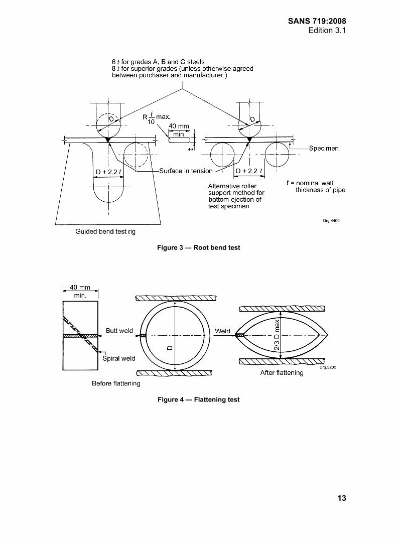
of the specified minimum yield stress of the steel plate or strip. 6.1.2 Welds After inspecting each pipe in the lot for compliance with 5.2.1, visually examine all the welds, the heat-affected zones and the surrounding parent metal in each pipe for compliance with the requirements of 5.2.2.2 or 5.2.2.3 (as appropriate) and, when relevant, 5.2.3. 6.2 Destructive tests 6.2.1 Transverse tensile test From a cold-flattened section of pipe cut a test specimen conforming to figure 2. Do not remove the weld reinforcement. Determine the ultimate tensile strength (UTS) by the method given in SANS 6892. 6.2.2 Root bend test (electric fusion welds) From a cold-flattened or as-cut section of pipe, cut a specimen conforming to figure 3. Remove the weld reinforcement and file the arrises to a radius not exceeding 10 % of the thickness of the specimen. Bend through an angle of at least 180° in a rig conforming to figure 3. Check for compliance with the requirements of 5.2.2.2.11. 6.2.3 Flattening test (electric resistance welds) Cut a cylindrical test specimen conforming to figure 4. Ensuring that the weld is at the point of maximum bending (see figure 4), flatten the specimen between two parallel flat surfaces until the outside diameter to which the compression is applied is reduced to not more than two-thirds of its original value. 6.3 Hydraulic test Subject each pipe that is presented for hydraulic testing to the relevant hydraulic test pressure specified in 5.2.4. Maintain the pressure for at least 5 s and inspect the welds for leaks and to check for compliance with the requirements of 5.2.4. 6.4 Coatings and linings When applicable, inspect and test the coatings and linings of the pipes for compliance with the requirements of 5.2.5. 7 Marking Except if otherwise specified, the name or the trade name or the trade mark of the manufacturer shall be hardstamped on the pipe. Additional marking required by the purchaser may be legibly painted or stencilled on each pipe.
SANS 719:2008 Edition 3.1
12
Figure 1 ― End preparation for field welds
Figure 2 ― Transverse tensile test specimen
SANS 719:2008 Edition 3.1
13
Figure 3 ― Root bend test
Figure 4 — Flattening test
SANS 719:2008 Edition 3.1
14
Annex A (normative)
Notes to purchasers
A.1 The following requirements must be specified in tender invitations and in each order or contract: a) the grade of pipe required (see 4.2 and 4.3); b) when relevant, that test certificates are required (see 4.4); c) the random length or exact length of pipe required, as relevant (see 5.1.1); d) the nominal size (see 5.1.2); e) when relevant, the nominal wall thickness (see 5.1.3); f) whether the ends are to be plain or are to be prepared for field welding and, in the latter case,
the type of end preparation, if other than as specified (see 5.1.5 and figure 1); g) when relevant, that the height of inner weld reinforcement shall not exceed 1 mm (see 5.2.2.2.7); h) when relevant, that the pipes are to be coated or lined, or both, and the type of coating and/or
lining required (see 5.2.5); i) marking (see 7.1); and j) if required, additional markings (see 7.1). A.2 The following requirements must be agreed upon in writing between the manufacturer and the purchaser: a) the chemical composition and physical properties of the steel plate or strip of pipes other than of
Grade A, B or C (see 3.2 and 3.3); b) the yield stress, if the plate thickness exceeds 18 mm (see 4.3 and table 1); c) the nominal outside diameter, if other than as specified, and in the case of pipes of nominal
outside diameter of more than 1 250 mm, the tolerances on O.D. (see 5.1.2); d) the wall thickness, if other than as specified (see 5.1.3); e) the maximum hydraulic test pressure, if other than as specified (see 5.2.4); f) when relevant, the type of coating or lining or both (see 5.2.5); and g) the size of the root bend test former, if other than as specified (see figure 3).
SANS 719:2008 Edition 3.1
15
Annex B (informative)
Quality verification of electric welded low carbon steel pipes
When a purchaser requires quality verification on an ongoing basis of electric welded low carbon steel pipes produced to this standard, it is suggested that, rather than concentrating solely on the evaluation of the final product, he also direct his attention to the quality management system applied by the manufacturer. In this connection it should be noted that SANS 9001 covers the provisions of an integrated quality system.
Bibliography SANS 9001/ISO 9001, Quality management systems – Requirements.
© Standards South Africa