Embed Size (px)
Citation preview
Sounding Reference signal measurement in LTE system
Eunjeong Shin*, Jeawook Shin**
*ETRI(Electronics and Telecommunications Research Institute), Korea
**ETRI(Electronics and Telecommunications Research Institute), Korea
[email protected], [email protected]
Abstract— The SRS are physical signals transmitted in uplink to enable the eNB to estimate the CSI over a range of frequencies in LTE system. The estimation of the CSI assists the eNB scheduler to properly allocated radio resource to the UE. The SRS transmission can be also be used to support downlink beamforming. The sub-frame in which SRS is transmitted by any UE within the cell is signaled via cell specific broadcast signaling, there are 15 possible sets of subframe in which SRS may be transmitted within each radio frame. The SRS is based on the extended zadoff-chu sequence and transmitted in the last SC-FDMA symbol of an uplink subframe, the SRS transmitted by the UEs are multiplexed in the time and freq. domain through configuring SRS periodicity SRS, frequency comb pattern, and SRS bandwidth. Different sets of UE-specific sounding signals are independently allocated for SRS transmission, including transmission bandwidth, frequency comb pattern, cyclic shift. In this paper, transmission subframe, bandwidth, freq. comb pattern, for it suggests ways to reduce the measurement performance and HW complexity of the UE between the Sounding RS separated by a Cyclic shift value and Timing offset measurement method.
Keywords— LTE,SRS,Measurement
I. INTRODUCTION
The SRS are physical signals transmitted in the uplink to enable the eNB to estimate the channel state information over a range of frequencies. The estimation results in eNB assists the scheduler to properly allocated radio resource to UE. And to select different transmission parameters such as the in instantaneous data rate and uplink multi antenna transmission parameters for optimized uplink transmission. The SRS transmission can be used for uplink timing estimation as well as to estimate downlink channel conditions assuming downlink, uplink channel reciprocity. When up/Down channel reciprocity is assumed, SRS measurement can also be used to support downlink transmissions such as angle of arrival measurements on SRS to support downlink beamforming. SRS is not necessarily transmitted together with an uplink physical channel and when transmitted in conjunction with PUSCH, the SRS may cover a different and typically larger frequency region.
In this paper , by sending SRS transmission from multiple UEs to one SRS Transmission BW area , by utilizing the base sequence in the Transmission BW, and reducing the complexity of HW when distinguishing the UE in Cyclic shift it can.
II. SRS TRANSMISSION
The subframe in which SRS is transmitted by any UE within the cell is signalled via cell specific broadcast signalling. Cell specific parameter indicates 15 possibile sets of subframes in which SRS may be transmitted within each radio frame.
Reference signal sequence )()(, nr vu is defined by a cyclic
shift of a base sequence )(, nr vu according to
RSsc,
)(, 0),()( Mnnrenr vu
njvu
where RBsc
RSsc mNM is the length of the reference signal
sequence and ULmax,RB1 Nm . Multiple reference signal
sequences are defined from a single base sequence through different values of .
Base sequences )(, nr vu are divided into groups, where
29,...,1,0u is the group number and v is the base
sequence number within the group, such that each group contains one base sequence ( 0v ) of each length
RBsc
RSsc mNM . The sequence group number u and the
number v within the group may vary in time.
the base sequence )1(),...,0( RS
sc,, Mrr vuvu is given by RSsc
RSZC, 0),mod()( MnNnxnr qvu
where the thq root Zadoff-Chu sequence is defined by
10, RSZC
)1(RSZC
Nmemx N
mqmj
q
with q given by
31)1(
)1(21
RSZC
2
uNq
vqq q
759ISBN 978-89-968650-7-0 Jan. 31 ~ Feb. 3, 2016 ICACT2016
The sequence-group number u in slot sn is defined by a
group hopping pattern )( sgh nf and a sequence-shift pattern
ssf according to
30mod)( sssgh fnfu
if group hopping enabled, The group-hopping pattern )( sgh nf
is
( ) 302+8= ∑7
0=mod)in(c)n(f
i
issgh
where the pseudo-random sequence )(ic The pseudo-random
sequence generator shall be initialized with
30
RSID
init
nc at
the beginning of each radio frame where is cellID
RSID Nn .
The sequence shift pattern SRSssf given by
30modRSID
SRSss nf sequence shift pattern
If group hopping is disabled and sequence hopping is enabled, the base sequence number v within the base sequence group
in slot sn is defined by
( )sncν =
The pseudo-random sequence generator shall be initialized with
30mod230
ssRSID
5RSID
init
n
nc , cell
IDRSID Nn
29,...,1,0ss , configured by higher layers
Reference signal sequence )()(, nr vu can be defined as
sounding reference signal sequence.
nrnr p
vup )(
,)~(
SRS
~
The Cyclic shift p~ of the sounding reference signal is given
as
1,...,1,0~
8mod~8
82
ap
ap
csSRS
~csSRS
~csSRS
~
Np
N
pnn
n
p,
p,
p
,
Where 7,6,5,4,3,2,1,0csSRS n is configured separately for
periodic and each configuration of aperiodic sounding by the higher-layer parameters cyclicShift. apN is the number of
antenna ports used for sounding reference signal transmission
III. SRS MEASUREMENT
SRS Demodulation block operates in subframe units, definition of SRS transmission subframe is cell specific parameters.
eNB request an individual SRS transmission from a UE, or configure a UE to transmit SRS periodically until it is no longer necessary. The periodicity of SRS is 2,5,10,20,40,80,160,320ms. The SRS periodicity and SRS subframe offset within the period in which the UE should transmit its SRS are configured via a UE specific dedicated signaling parameters. The SRS transmitted by the UEs are multiplexed in the time and frequency domain through configuring SRS periodicity. Up to eight orthogonal SRS transmissions can be cod-division multiplexed over a frequency region using different cyclic shifts of the root zadoff-chu sequence. SRS transmission was not sufficiently flexible to support sounding from an increased number of UE antennas and an increased number of UEs due to use of semi-static RRC signalling for UE configuration. So aperiodic SRS transmission was introduced to complement periodic SRS transmission, where the eNB dynamically schedules a UE for SRS transmission on demand. It allows efficient management if a fixed set of time/frequency/code SRS resources for a larger number of UEs.
SRS transmission share a common set of cell specific SRS resources. It is subframe configuration period, subframe offset, SRS Bandwidth.
Different sets of UE-Specific sounding parameters are independently allocated for periodic and aperiodic SRS transmission including transmission bandwidth, periodicity, frequency comb pattern, and cyclic shift.
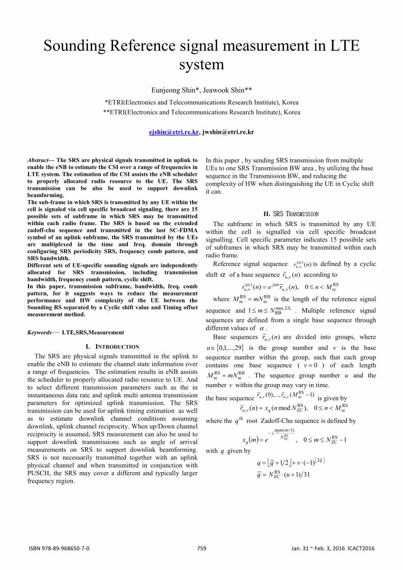
The figure below shows a top structure of the SRS measurement block.
RxANT1
RxANT0 Ue#M(M<8)
Ue#0
CPReMove
FFT
SRSReSource
UE Control/Subframe control
L1-Control
Ref.Gen
SRSReMap
SRSBaseRef.
Conj
Windowing
IFFT
De-Mapping
PeakDetector
FFTRSRPmem
SRS Measurement
Figure 1. Top structure of SRS measurement block
The SRS measurement block is enabled by L1 Control. L1 Control Block makes the enable signal by subframe
configuration period, subframe offset, SRS bandwidth. In the Received signal processing, CP removed, and changed
to frequency domain signal by FFT block, the SRS measurement block generate the SRS reference signal.
The generated reference signal is base reference signal which cyclic shift value is 0.
Then, conjugated base reference signal are lease squared by received signal.
*)()( ))(()(~)( krkrkG up
up
u , 1,...,1,0 RSscMk
P is antenna index.
760ISBN 978-89-968650-7-0 Jan. 31 ~ Feb. 3, 2016 ICACT2016
Then, least squared signal mapped in IFFT resource.
RSscM
RSsc
pu
pu
pu
pu MGGGG
1024
)()()()( 0,...,0),1(),...,1(),0(ˆ
Then 1024 point IFFT,
10242
11024
0
)()( )(ˆ1024
1)(
mkj
k
pu
pu ekGmg
1023,...,1,0m
IFFT size can be changed by system bandwidth. The IFFT
size is associated with a timing accuracy. The timing accuracy varies from system bandwidth.
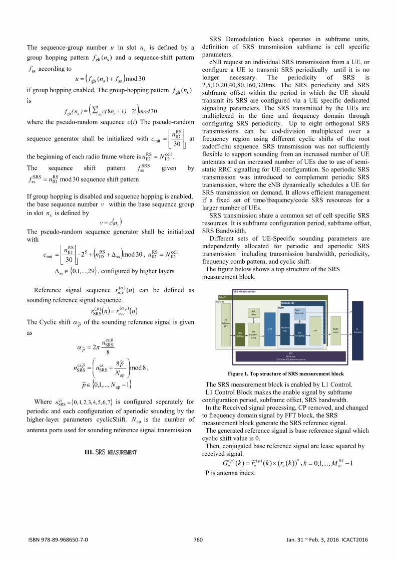
The out of IFFT, makes the impulse, then Find the greatest impulse in the UE-specific time-axis measures the timing offset.
The figure below shows the results of the IFFT output signal impulse when 8 UE transmits the SRS.
m01, m02 area is a windowing area corresponding to the base sequence. m51, m52 area is a windowing area corresponding to the cyclic shift 5 from the base sequence.
0 200 400 600 800 1000 12000
1
2
3
4
5
6
7
8
9timeOut
Figure 2. Windowing of IFFT output
Peak detector is a function block to find the greatest signal of the impulse. Peak detector also determines whether the SRS transmission. As shown in the following formula.
18/1024
0
)(
max)(
max
)(18/1024
1
)(
nnn
pu
pu
u
ny
ny
3
0
2)()( )(~)(p
pu
pu mgny
)(maxarg )(max nyn p
u
n
Estimated for each UEs channel signal by the windowing is
changed to the frequency domain.
10242
11024
0
)()( )(~1024
1)(
~ mkj
m
pu
p emgkG
)(~
)(ˆ )()( kGkH pu
p
It estimates the CQI as follows, average power per Resource block.
1
0
56
6
2)( )(ˆ
6
1)(
P
p
m
mk
pu
SRSu kH
PmCQI 16/,...,1,0 RS
scMm
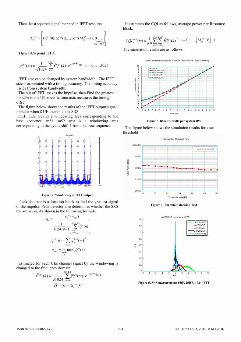
The simulation results are as follows.
Figure 3. RSRP Results per system BW
The figure below shows the simulation results for a set threshold
Figure 4. Threshold decision Test
Figure 5. SRS measurement PDF, 25RB, 1024 IFFT
761ISBN 978-89-968650-7-0 Jan. 31 ~ Feb. 3, 2016 ICACT2016
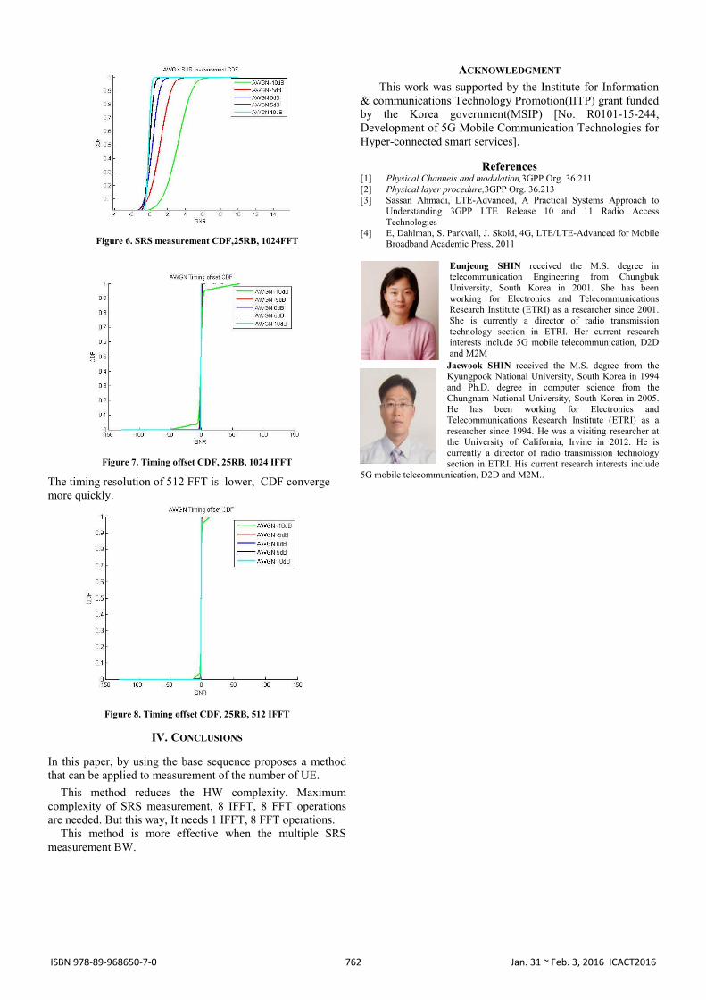
Figure 6. SRS measurement CDF,25RB, 1024FFT
Figure 7. Timing offset CDF, 25RB, 1024 IFFT
The timing resolution of 512 FFT is lower, CDF converge more quickly.
Figure 8. Timing offset CDF, 25RB, 512 IFFT
IV. CONCLUSIONS
In this paper, by using the base sequence proposes a method that can be applied to measurement of the number of UE.
This method reduces the HW complexity. Maximum complexity of SRS measurement, 8 IFFT, 8 FFT operations are needed. But this way, It needs 1 IFFT, 8 FFT operations.
This method is more effective when the multiple SRS measurement BW.
ACKNOWLEDGMENT
This work was supported by the Institute for Information & communications Technology Promotion(IITP) grant funded by the Korea government(MSIP) [No. R0101-15-244, Development of 5G Mobile Communication Technologies for Hyper-connected smart services].
References [1] Physical Channels and modulation,3GPP Org. 36.211 [2] Physical layer procedure,3GPP Org. 36.213 [3] Sassan Ahmadi, LTE-Advanced, A Practical Systems Approach to
Understanding 3GPP LTE Release 10 and 11 Radio Access Technologies
[4] E, Dahlman, S. Parkvall, J. Skold, 4G, LTE/LTE-Advanced for Mobile Broadband Academic Press, 2011
Eunjeong SHIN received the M.S. degree in telecommunication Engineering from Chungbuk University, South Korea in 2001. She has been working for Electronics and Telecommunications Research Institute (ETRI) as a researcher since 2001. She is currently a director of radio transmission technology section in ETRI. Her current research interests include 5G mobile telecommunication, D2D and M2M
Jaewook SHIN received the M.S. degree from the Kyungpook National University, South Korea in 1994 and Ph.D. degree in computer science from the Chungnam National University, South Korea in 2005. He has been working for Electronics and Telecommunications Research Institute (ETRI) as a researcher since 1994. He was a visiting researcher at the University of California, Irvine in 2012. He is currently a director of radio transmission technology section in ETRI. His current research interests include
5G mobile telecommunication, D2D and M2M..
762ISBN 978-89-968650-7-0 Jan. 31 ~ Feb. 3, 2016 ICACT2016