Embed Size (px)
Citation preview

Sound Wave Scattering by Cylindrical Shellswith Internal Structures
by
Sewon Park
B. S. Seoul National University (1988)S. M. Massachusetts Institute of Technology (1992)
Submitted to the Department ofOcean Engineering in the Partial Fulfillment of
the Requirements for theDegree of
Ocean Engineerat the
Massachusetts Institute of Technology
February 1995
© 1995 Massachusetts Institute of TechnologyAll rights reserved
Signature of Author . . . . . . . . . . . . . .
Department of Ocean EngineeringJanuary, 1995
Certified by . . . . .
Profesor Ira DyerThesis Supervisor
Accepted by .c--" Professor A. DouglasTa'michael
Chairman, Department Graduate Committee
MiASSACHUSETT S INSTiriTUfTEOF TECHNOLOGY
JUL 2 81995
LIBRARIES

Sound Wave Scattering by Cylindrical Shells with Internal Structures
by Sewon Park
Submitted to the Department of Ocean Engineering in partial fulfillment of therequirements for the Ocean Engineer degree
Abstract
In this thesis I study the mid-frequency scattering properties at beam incidencefrom different kinds of cylindrical shells; empty shell, shell with stiffening rings, shell withinternal structures only and layered shell, the latter having the same internal structures.The measurements and analyses were conducted over a mid-frequency range of 2 < ka <12, where k is the acoustic wave number in water and a is the radius of the shell. Bothtime and frequency domain representations of the scattered field are presented to illustratethe evolution of observed backscattering processes.
The empty and layered shells have almost the same decay pattern of the signalsbeyond the initial return. Also the shell with rings and the shell with internal structuresonly have closely the same decay pattern. The decay rate for the empty shell is0.064dB/gsec. A similar decay rate is observed for the layered shell, that is 0.071 dB/sec.Decay rates for the ringed shell and internaled shell are smaller, they are 0.051 dB/gsec and0.045dB/tsec.
The distribution of the rings store energy and become the major source of radiationat later time. The internal structures also influence the radiation at later time. The rubberattachments of the internal structures limit the shell's radial motion to prefer twomaximum and minimum ring motion. Therefore, the shell with internal structures andlayered shell show dominant second ring frequency response.

Contents
1. Introduction .............................................................. 4
2. Shell Design ........................................ 7
3. Dynamic response of infinite cylindersat beam incidence; lumped model .............................. 10
4. Sound scattering from the four different shellsat beam incidence; analysis of measurement ................ 184.1 Introduction ........................................................ 184.2 Empty shell ....................................... 184.3 Shell with stiffening rings .................................... 204.4 Shell with internal structure ................................. 234.5 Layered shell ....................................................... 25
5. Conclusion ................................................................. 44
Table of Figures ............................................................. 49
Table of Tables ................. 5................. ........... ......... 51
References ..................................................................... 52
Appendix A ................................................................... 53
Appendix B .......................................................... 56

1. Introduction
Acoustic scattering by four different cylindrical shells at normal incidence has been
analyzed. The incident wave is a short transient, such that we can exclude the interference
between the geometric field, which is initially scattered from the shell, and the radiation
field caused by the induced elastic waves in the shell. Therefore, the scattering can be
easily divided into the geometric field and the elastic field. The geometric field fills about
the first 30 pisec of the scattering signal. It depends on the geometry of the shell and the
basic properties of the shell like mass or elasticity of the shell. After the geometric field,
the induced waves which travel through the shell and its internal structures influence the
scattering process, until the whole energy received by the shell from the incident sound
wave, is consumed and reradiated into the water. Therefore, the different properties and
different structures of the shell make different contribution to the scattering in both the
geometric field and elastic field.
This research is motivated by an interest in the acoustic properties of ship and
submarine hulls. Internal structures are often resiliently mounted to the hull to inhibit the
local transmission of the vibration energy from machinery and supporting structure to the
hull. The presence of the resiliently mounted structures and structural discontinuities
imposed by hull stiffeners must influence the acoustic scattering properties of the hull.
Experimental and analytic studies of the scatter generated by plane wave
insonification of infinite cylindrical shells have been presented in a variety of references.
The effect of induced elastic waves and the azimuthal dependence of the scattered field
have been studied by Feit[1] and Marston[2,3]. Similar analytic studies of the plane wave
scattering from infinite cylindrical shells at oblique incidence, and the influence of helical
elastic waves, have been studied by Felsen and Ho[4,5,6]. There are a few experimental or
analytical studies of acoustic scattering from finite cylindrical shells or internally loaded
4
shells. Maze et al [7] conducted experimental and theoretical studies of the influence of
the resonant excitation of elastic waves on finite solid cylinders at normal and axial angles
of incidence. Guo[8,9] has analytically studied the scattering effects of infinite cylinders
internally loaded with two dimensional mass spring systems or elastic plates. Scattering
from finite cylindrical shells with internal structures are studied by Corrado[ 10]. He
conducted experimental studies of the scattering from three of the shells considered here;
empty shell, ringed shell and internalled shell, for various angles of incidence. He also
analytically studied scattering from a finite empty cylindrical shell, but with perfectly
reflecting endcaps.
Scattering by a cylindrical shell in water is influenced by the induced dynamic
interaction between the exterior shell and the internal structure. Comparing the scattering
from the different shells helps us to understand and interpret the dynamics of the scattering
process. In the empty shell case, many fundamental scattering processes that are common
to the more complex shells are evident, and are more readily interpreted. In the shell with
ring stiffeners, the stiffness of the shell is changed along with its mass, and provide
discontinuities along the shell to axially propagating elastic waves. In the shell with
internal structures, the role of the internal structures is added to the ring stiffened shell
case. In the case of the layered shell, dissipation of the elastic waves along the shell by the
damping material between the sandwich shell may decrease the effect of the axially
traveling waves.
Shell designs are described in Chapter 2.
In Chapter 3, I study the lumped system response of infinitely long cylindrical
shells. Such simple models are used to study the initial scattering by the empty shell, ring-
stiffened shell and shell with internal structures. The stiffening rings and internal structures
are simplified as a uniform mass load. The analytical results are not close to the
experimental data. The stiffness changes by the distribution of the rings are not modeled
5

by the uniform mass load. Also the simplified spring, damper and mass model could not
well model the internal structures. The uniform mass loading assumed decreases the initial
scattering by the shell. But the mass connected to a shell by a spring and a damper does
not influence initial scattering much.
The measured backscatter at beam aspect from the different shells are examined in
Chapter 4. Both time and frequency domain representations are shown for the different
shells; empty shell, ring-stiffened shell, shell with internal structures only and layered shell
with the same internal structures. The internal structures change the basic scattering
properties of the shell and increase the initial scattering about 2dB. This small influence of
the internal structures is limited to the initial scattering. The elastic field decay rate for the
layered shell is similar to that of empty shell for times less that 800 tsec. The rings and
internal structures in the ring-stiffened shell and complex shell provide the additional
energy storage. Therefore, the decay rates for these two shells are lower than those for
empty shell and layered shell. Every shell has dominant scattering frequencies that relate to
elastic resonance frequencies. Variations of these frequencies cause changes in the major
scattering sources of the shell. Rings in the stiffened-ring shell, internalled shell and
layered shell become the major source of the radiation. The shell itself is the major
scattering source for the empty shell for all time, but for the others at later time, about
after 60 psec, the influence from the internal structures becomes dominant.
6

2. Shell Designs
The design parameters of the four shells are summarized in Table 2. 1. See the
Conti and Dyer [11] and Corrado [10] references for primary information on these
designs. The design of the empty shell serves as the base exterior shell design for the other
three shells. The basic shell dimensions are illustrated in Figure 2.1. The ring stiffened
shell is comprised of the same exterior shell design configuration, but stiffened by four
large nickel rings that are unequally spaced along the axis of the cylinder, as illustrated in
Figure 2.1. The total mass of the rings equals the mass of the exterior shell, and they
introduce structural impedence discontinuities to waves propagating on the shell. The
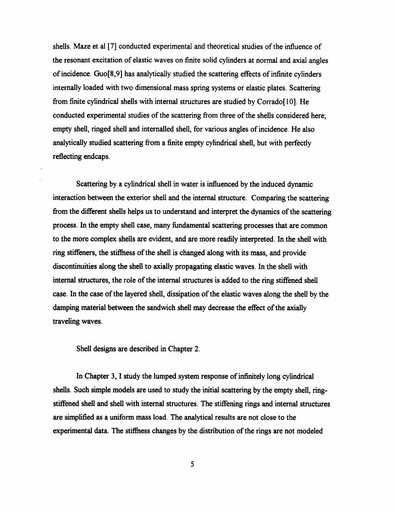
internally loaded, complex shell was designed to provide a means of evaluating the effects
of resiliently mounted wave bearing structures. The internal structures are supported from
the rings of the stiffened shell, of the same configuration discussed above and illustrated in
Figure 2.1. The internal structures consist of a quadrant symmetric arrangement of one
inch diameter Delrin rods interconnected by cylindrical stainless steel masses as illustrated
in Figure 2.2. The stainless steal masses are individually supported from the ring stiffeners
by independent, triangular shaped rubber blocks made of EAR C 1002 Isodamp rubber.
The various internal components are all secured to one another with an epoxy compound.
The total mass of the internal structures and ring stiffeners is approximately three times
greater than the mass of the shell. In the layered shell, a rubber layer is sandwiched by the
two concentric shells each 0.000532m thick, over the complex shell. The rubber material
in this sandwich is 0.001m thick and also made of EAR C2206-03 Isodamp rubber.
7

Table 2.1 Summary of Model Design Parameters
ConfigulationShell & Ring MaterialLength OverallShell RadiusShell ThicknessRing ThicknessRing WidthMass Ratio, Rings/shellMass Ratio, Internals & Rings/ShellMass Ratio, Internals & Rings &Layer/Shell
Ni-2000 86m
0.05537m0.000532m0.01m0.0125m1
3
4
Approx. Shell Material PropertiesYoung's Modulus, E 2.2 x 10¹¹ N/m 2
Density, p 8900 kg / m3
Poisson's Ratio, v 0.31Compressional Plate Wave Speed 5270 m/sTransverse Shear Wave Speed 3100 m/s
Approx. Delrin Material PropertiesMeasured Dynamic Modulus, E 3.7 x 10⁹ N / m2
Density, p 1400 kg/ m3
Poisson's Ratio, v 0.35Measured Compressional Speed of Rod 1625 m/s
Approx. Rubber Material PropertiesMeasured Dynamic Modulus, E 5.0 x 10⁸ N / m2
Density, p 1289 kg/ m3
Poisson's Ratio, v 0.28
8
_� __ �-
�II_-
�-
�_ _-
�I-
-
_ _-
- I-
_ _
Shell Material: Ni-200Shell Thickness: 0.000532 m
Endcaps: Right Circular Cones with Spherical EndsDimensions in meters
2650
I
.0931No
.128 .190 .235 .093
0.739 1
0.862
0.111
-1
Figure 2.1 The Design Configulation of the Empty Shell Model and the location of theRing Stiffeners (From C. Corrado)
Figure 2.2 The Configulation of the Internal Structures (From M. Conti)
9
0.046R
r
- -
'- wII w ~~~~~~ 1 - -
! A---
I .! l , . -
CIIII~CLIIIUI. .
I. . , .
r,
I !
I

3. Dynamic response of infinite cylinders at beam incidence;lumped model
I have studied the initial or geometric scattering response of simplified models of
the cylindrical shells. The initial return from the shell may depend only on simple
properties of the shell, because the detailed dynamics of the shell mainly influence the
scattering later in time. At beam incidence, radiation by the induced elastic waves can not
affect the geometric return. Therefore, by studying a simplified model based on basic
properties of the shell, we might understand the initial scattering process. The basic
properties of the shell may include the geometry or structure of the shell, and its stiffness
and mass.
I assume that the shells are continuous, infinitely long, cylindrical shells. Therefore,
the effect of the elastic waves traveling along the axis of the cylinder is neglected. The
empty shell is modeled by an infinite uniform cylinder. The masses of the rings are added
to the infinite cylinder to model the ring-stiffened shell, by distributing them uniformly in
the axial direction. Therefore, the structural impedance discontinuity along the shell is
neglected. Also the stiffness increase by the ring distribution is not modeled well. For the
shell with internal structures, the mass of the internal structures is included with a spring
and damper model for the triangular shaped rubber blocks. The rubber block has many
natural frequencies and many complex mode shapes.
A finite element method is used to find the natural frequencies and mode shapes of
the rubber block. The two dimensional motion of the rubber block with the internal mass is
analyzed. Figure 3.1 shows the lowest natural mode shape and the first 40 natural
frequencies of the rubber block. The lowest natural frequency of the rubber block with the
internal mass is ka=0.6. The damper has damping which is in inverse proportion to
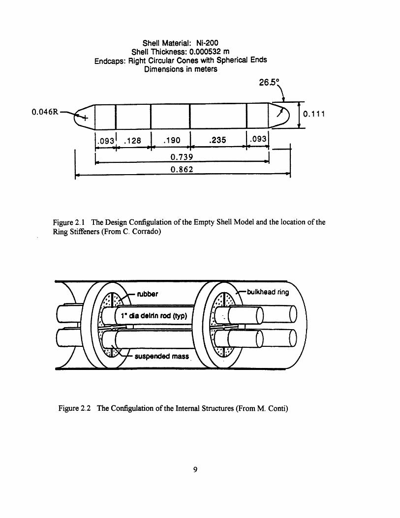
frequency. Figure 3.2 shows the diagrams for the shell with stiffened ring model and the
shell with internal structure model.
10

I calculated the impulse response function for three of the four kinds of shells;
empty shell, ring-stiffened shell and complex shell. The basic equations and formulations
are shown in Appendix A. Figure 3.3 shows the Gaussian bandpass filter impulse response
used in calculations, which is the same Gaussian filter used in experimental data analysis.
Magnitudes of the impedance functions, for a force F applied as in Fig 3.2, are
shown in Figure 3.4. The extra masses affect the impedance function throughout the entire
frequency range. The effect becomes larger after ka=2. The maximum impedance is shown
at the resonance frequency of the spring/mass model in the internal shell case. After the
maximum impedance, the impedance function of the shell with internal structure model
becomes identical to the ring-stiffened shell model. Therefore, when the frequency is
larger than the resonance frequency of the rubber block/internal mass system, the internal
structure has no effect on the vibration of the shell. The impulse response function in
Figure 3.5 shows that there are no differences between the ring-stiffened shell and the shell
with internal structures. But there is a 30 % decrease of the impulse response from the
empty shell case to the other two cases. The initial returns from the shells have a negative
sense, and that is consistent with the pressure release cylinder.
The uniform mass loading of the rings and radiation inertia, which vibrates with the
shell, creates the response decrease. But the mass of the internal structures does not
influence the response. Because the impulse frequency band excludes the resonance
frequency of the internal structures, hardly any energy can propagate through the spring to
vibrate the internal structure. The impulse responses are calculated with different
resonance frequencies of the internal structure. The impulse response return magnitudes
are decreased as the resonance frequencies of the internal structures are increased. Figure
3.6 shows the impulse response function depends on the resonance frequencies of the
internal structure. The simple spring and damper model can not contribute to the
scattering much regardless of the resonance frequency of the model.
11

I I I II )
I~~~~~It I I
30
u2. 0
0co0
0 10 20 30 40 50Mode
Fig 3.1 Natural frequencies of the rubber block with delrii and stainless steel mass inside.At 10kHz, ka=2.3.(up) Lowest natural modeshape for the rubber block with delrin andstainless steel mass inside. Motion is caused by a force acting on the arc, and parallel tothe vertical axis.(down)
12
50
x
MringMshellMrad
I -I -
Rsprung
x
Rrad
Msprung
Ksprung
M
Rrad
Fig 3.2 Diagram for Cylindrical Shell with Stiffening Rings (up). Cylindrical Shell withInternal Structures Model (down). The spring mass, sprirng and resistance refers to thesprung internal structures.
13
il F
il F

1
0.8
0.6
0.4
0.2
n
0.1
0.05
0
-0.05
v
-400
50 100 150 200Frequencv. IdHz
-200 0Time. microsec
200
250
400
Fig 3.3 Gaussian Bandpass Filter (up), mean 27.3 kHz and standard deviation 13.2 kHz.Gaussian bandpass filter Impulse Response (Down), 6 dB down at Band Edges of theFrequency Range 2.75 < ka < 11.7
14
IIII
-- -- -- -- -- -- I- -- -- -- -- --II
·r---r---------r--·-r-r------ l-- -llr-~~~~~~~~~~~~~~~~~~I
I
-- -- -- -- -- -- - -- -- -- -- -- -I
i-I
--------------------------- ---- -..i. ,I
II... .. ... .. ... .. ... .. ... .. ..
I
--------------------------------------
.
- I
~I q
]o

107 -- '--- ----- - ; °-;J-.q-:;-'L '- 1 -- I--;-; r.__._ _ l. j_ _ L J. J J ---- "--- - ,.. , _. & , *L. i . i, ,, * I * , I m .m .
------ -,--,- .-..t.L --- I --- - -- " J rLrLr -i " i-¥-' r
UI ~~~ ~ --I II I I 111 (1 -L.... - : - - ;- *- - --- - - - -- - - --,- ' r
---- -- r-|--0- L~ 1 9---- d�-V--$-S7 rL; J @
-- - -----M- -o th -e n F t f ---- -- - - - -- -- (--Em r s----- i----- -- T.-- -i i !.. --- i ---- T-- -
.... ._j___,..__B_ - -n-->- rr o- - r
filterei b iMui i i g i3. i i i i m i iiiI f/ I ''''' 1 * * 1 0 2.... J__;_, z·l--- _ * _......-- 3*4 Mantd of---r - - - -* - -n- -* -F o f or e - -te - - l- -m p -e r r
filtere i i Ii I *II I......- ,-----... ...---'---- - -rr------�-- -I-rrrI * I I I * I * I I I I I J i i . i
10 1 0 10 4 10 2
filtered by the Gaussian function in Fig3.3.
15

0.1
-0.05. ..................................
-0.1 ..-...-..-.......- ... ...........................................
-0.15-100 0 100 200 300 400
Time, microsec
Fig 3.5 Gaussian bandlimited impulse response fiunction of three shell models (-- Emptyshell, -. Shell with stiffening rings, - Shell with internal structures)
16

n 4U. I
0.05
0
-0.05
-0.1
_n i-u. I P
-0.066
-0.068
-0.07
-0.072
-0.074
_n n7A
50 100
Time, microsec
150
2 4 6 8 10 12
Resonance frequency, ka
Fig 3.6 (Up) Bandlimited impulse response functions with increasing resonancefrequency of the internal structure. Arrow shows the changing direction as the resonancefrequency increases from ka=0.6 to ka=12. The break line shows the impulse responsefunction for the empty shell. (Down) Maximum return in impulse response as theresonance frequency changes.
17
-----,-------- ..-- ------------- ----.
-I t- - - - - - - - - -!'-- -- #------.__~____,_ ____ _
I
0------------------- -0
: 0,o>
Cl
00------00
0 O000 0iII
i i!
I
-
3
------------- :------------
-- ----- - -- ----- ----- - -----
...-- -- - ------------
I.-
---.v v 0
4. Sound scattering from the four different shells at beamincidence; analysis of measurements
4.1 Introduction
From the analytical calculation of a simple lumped approximation for an infinite
shell, I have studied a few of the possible bases of scattering from the actual shell and how
the mass affects the initial scattering. In the real experimental data analysis, we also have
to consider the influence of the finiteness of the shell and axially traveling waves. The
structural design differences of the shells also affect the sound scattering. Distribution of
the rings and internal structures change the basic properties of the shells and influence the
scattering process.
Beam incidence, monostatic sound scattering data are analyzed for each of the four
shells.
4.2 Empty shell
In the empty shell, at least for beam incidence, we can consider this as a infinite
shell only if the length of the cylinder is long enough. The waves on the shell, which are
induced by the plane sound wave, propagate in the axial as well as circumferential
direction. If the axial waves are damped out before they get back after they hit the end of
the shell, we may consider this shell as an infinite shell.
18
The bandlimited impulse response of the empty shell at beam incidence is shown in
Figure 4.2.1 . This time domain representation of the scattering results from a
deconvolution of the source signal from the scattered field measured at a radius of r=2m.
The initial return from the shell has a negative sense that is consistent with a pressure
release surface. After the geometric return, there are a series of returns which have a 62-
66 ,sec period. These are produced by radiation from the induced circumferential
compressional wave and have an opposite sense with respect to the initial return. The
radiation losses that occur as the induced compressional wave circumnavigates the shell,
are partially the cause for the observed decay. The logarithm of the magnitude of the
analytic signal representation of the backscattered signal is shown as a function of time in
Figure 4.2.2. I have used this representation to calculate the decay rate of the
backscattered signal. A least squares linear fit of the envelope yields a broadband
amplitude decay rate of 0.064 dB/ptsec. In this calculation I exclude the initial return and
the returns that are less than -75dB, as the latter could include noise.
Figure 4.2.4 shows the same analysis as in Figure 4.2.2 but in different frequency
bands. I used three partially overlapping Gaussian windows to observe the decay rate of
signal returns depending on the frequency band. Each window is shown in Figure 4.2.3. I
choose the low frequency band from 10kHz to 24kHz (2.35 < ka < 5.64), the mid
frequency band from 20kHz to 34kHz ( 4.70 < ka < 7.99), and the high frequency band
from 30kHz to 44kHz ( 7.05 < ka <10.34 ). In each band, the decay rates are same, and
are about 0.063dB/psec. At beam incidence the transverse shear waves propagate with no
radial displacement component and do not contribute to the scattering. The decay of the
returned signals is partially caused by the radiation losses as the compressional wave
circumnavigates the shell. So these radiation losses do not depend on the frequencies. But
because the rate is so much smaller than the theoretical radiation loss rate of
0.089dB/psec,we must consider that the energy is partially stored in the finite shell, no
doubt due to induced compressional axial waves[12].
19
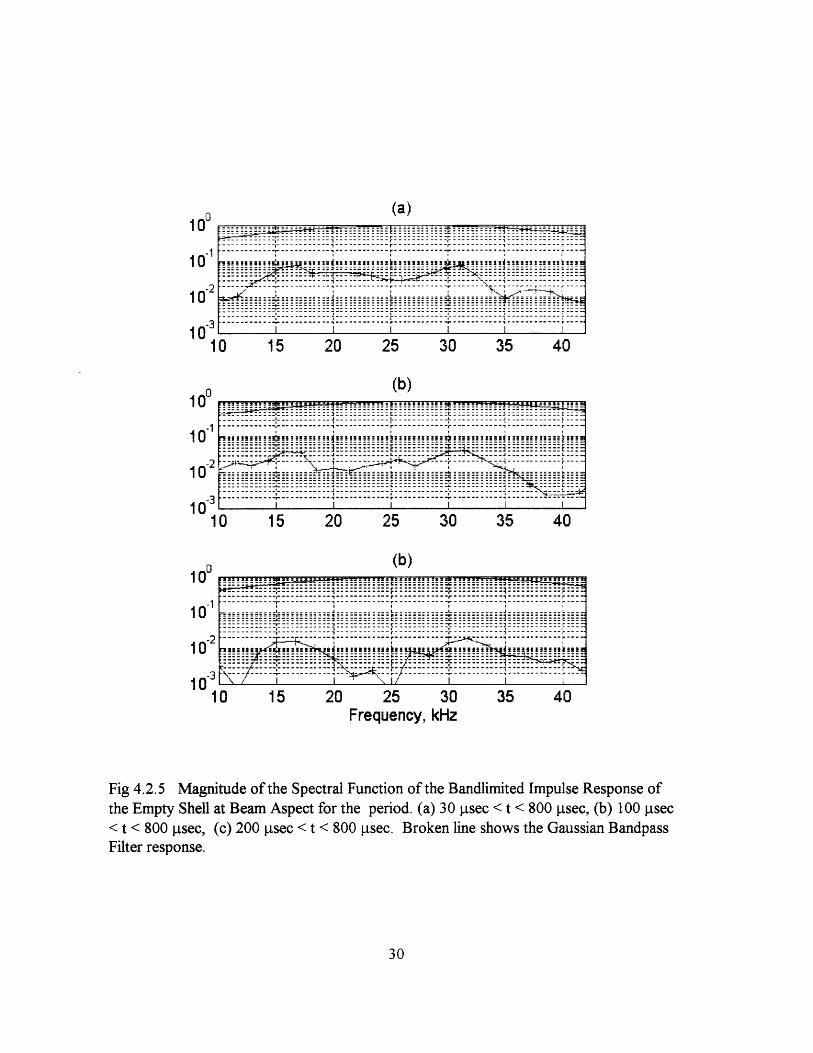
The speeds of the poorly radiated flexural waves are not fast enough to travel all
the way to the end of the shell. In the frequency bands I used, the time it takes for flexural
waves to travel the entire shell is 3200 - 1600 jtsec depending on the frequency. So the
signal returns for the empty shell are only caused by the induced compressional waves.
These induced compressional waves have to have specific periods and frequencies to fit
into the shell circumference. The first ring frequency is 15kHz with a 66~tsec period. The
second ring frequency is 30kHz with a 33g1sec period. The magnitudes of the spectral
function from the Fourier transform of the bandlimited impulse response are shown in
Figure 4.2.5. To exclude the initial return, the first 30gsec of the data are excluded. In the
empty shell case, after 800ptsec, the signals are too small to consider as a scattering signal
from cylinder. So the data after 800gsec are excluded. Figure 4.2.5 shows the dominant
frequency responses to be at the first and second ring frequencies. The analysis for the
total time has the shape of the Gaussian bandpass filter, except for the dominant responses
near the first and second ring frequencies. This shape disappears as the analysis goes to the
later time.
For the empty shell, the induced compressional waves mostly control the scattering
process after the geometric return. In our frequency band, the first and second ring
frequency waves are mostly acting throughout the scattering process. The decay rate is
determined only partially by the radiation loss during these compressional waves
circumnavigating the shell, since the measured values are only about 70% of the
theoretical decay rate.
4.3 Shell with stiffening rings
20

In the case of the shell with stiffening rings, the axial wave motion can affect the
scattering more strongly. The induced flexural waves do not influence the scattering
process of the empty shell, because flexural waves are too slow for the overall length. In
the ring-stiffened shell, these flexural waves propagate to the rings, interact with rings, and
radiate. The time it takes to excite the shortest bay can be calculated by the round trip
travel time for flexural waves. I used flexural wave group speeds in a plate of the same
thickness of the shell to calculate the round trip time. The round trip time is about
350isec at a frequency of 27 kHz. So I expect that scattering by the shell itself may be
dominant before 350g.sec. The scattering by the rings, which are exited by induced
compressional and flexural waves between the rings, may be the major effect on the
scattering process after 350[sec.
The bandlimited impulse response is shown in Figure 4.3.1. The geometric return
is about same as for the empty shell. But the elastic response after the initial return lasts
longer than that of the empty shell. Figure 4.3.2 shows the logarithm of the magnitude of
the analytic signal representation of the bandlimited impulse response. I extract two decay
rates. The first decay rate of 0.05 ldB/gpsec is calculated from the first 350gsec of the
signal. This is the decay rate before the flexural wave can excite the shortest bay. The
signal after 350ptsec has a 0.01 ldB/!sec decay rate. Therefore, after the bays are exited,
the decay rate is decreased to one fifth. But even before one of the bays being excited, the
decay rate is still smaller than the empty shell case. This is so because the rings can be the
energy transfer mechanism during this time.
Figure 4.3.3 shows the logarithm of the magnitude of the envelope of the three
different frequency bandlimited impulse responses. I extracted the decay rates for these
frequency bands. Because the flexural waves are dispersive, the time it takes for the
flexural waves to excite the shortest bay is different for each frequency band. Before the
flexural waves excite the shortest bay, the decay rates are 0.030dB/psec for the low
frequency band, 0.056dB/sec for the mid frequency band and 0.085dB/psec for the high
21

frequency band. After the flexural waves excite the shortest bay, which are after 450 !.sec
for low frequency band, after 350 psec for the mid frequency band and after 250 tsec for
the high frequency band, the decay rates decrease remarkably. These are 0.0032dB/psec
for the low frequency band, 0.0066dB/jsec for the mid frequency band and
0.0114dB/ptsec for the high frequency band. These decay rates increase as the frequency
band goes higher. Compared to the empty shell case, which have the same decay rates for
all three frequency bands, the decay rates for the shell with stiffening rings case depend on
the frequency band.
In the shell with stiffening rings, the early decay rates are smaller than the empty
shell. Hence, the ring stiffeners and the bays between them must provide the energy
storage mechanisms to decrease the radial amplitude at the shell exterior. And at later
time, the rings and bays radiate the stored energy.
Magnitudes of the spectral function of the bandlimited impulse response function
are shown in Figure 4.3.4 and Figure 4.3.5. The Fourier analysis of the first 30psec to
350ptsec signal is shown in Figure 4.3.4 (a). The break line shows the Gaussian bandpass
filter that can be interpreted as the spectral function for the input impulse signal. The
Fourier analysis of the first 350p±sec response has the shape of the input signal. Figure
4.3.4 (b) shows the magnitude of the spectral function for the 3501tsec to 120011sec
response signal. These still reflect the shape of the input signal.
Figure 4.3.5 shows the magnitude of the spectral function of the bandlimited
impulse response for different time periods. The spectral density for the 30iisec to
1200psec response has peaks near 17kHz, 22kHz and 31kHz, the first and third of which
may correspond to the first and second ring frequencies. But these frequencies, if they are
the ring frequencies, are shifted a little to higher frequencies compared to the empty shell
case. These frequency shifts, especially for the second ring frequency, are more noticeable
especially when the first 100lsec or 200tsec response signals are excluded as shown in
22

figure (b) and (c). The shifted ring frequencies, especially evident at t>100sec, indicate
that the main scattering sources are moved from the shell to the rings. Because the mean
circumference of the rings is smaller than that of the shell, the induced compressional
waves traveling through the rings have higher ring frequencies than those of the shell. The
mean ring radius is 9% smaller than the shell radius, and can easily account for the
observed values. But the 22kHz peak has no ready explanation. Nonetheless, the
agreement of the prediction with the measurement at 17 and 31 kHz suggests quite
strongly that these are indeed related to ring motion.
When the shell with stiffening rings is insonified by the plane wave, first the
induced compressional waves, which circumnavigate the shell, are the main source for the
scattering. After axial flexural waves reach the rings the scattering from the rings becomes
the dominant scattering process. Therefore, the ring frequencies are more readily observed
in the spectral function of the response for the later time, as we have seen in Figure 4.3.5.
4.4 Shell with Internal Structures
The internal structures of the shell may provide additional energy storage for the
scattering process. The interaction with the internal structures might be frequency
dependent. Figure 4.4.1 shows the natural frequencies of the internal structures. These
natural frequencies are analytically calculated. The longitudinal and flexural coupled
motions in the derlin rods connected to stainless steel masses are considered in this
analysis. The analysis, summarized in Appendix B, shows that the modal density of the
internal structures in our frequency band is high, and we can consider that the internal
structures respond through the entire frequency range.
23

The bandlimited impulse response of the shell with the internal structures is shown
in Figure 4.4.2. There is about 25% increase in amplitude of the first return(about 1.9 dB)
compared to the empty shell case. Thereafter, the responses become more complicated
than the shell with stiffening ring case. But the decay rates from the logarithm of the
magnitude of the analytic signal representation (Figure 4.4.3) are 0.045 dB/gsec for the
first 350 gsec and 0.0081 dB/!gsec for the time after 350 psec, and are similar to those
from the shell with stiffening rings. The decay rates for the different frequency band are
shown in Figure 4.4.4. The decay rate increases when it goes from the low frequency band
to the mid and high frequency bands. These rates are 0.032 dB/gsec for the low frequency
band, 0.078 dB/gsec for the mid frequency band, and 0.076 dB/gsec for the high
frequency band. The decay rate seems to be unchanged when it goes from mid to high
frequency. After the flexural wave transition, the bays, which are excited by the flexural
waves, influence the scattering, with decay rates of 0.0011 dB/gsec, 0.0108 dB/gsec and
0.0087 dB/gsec. These increase from low to mid and high frequencies, although the high
frequency value is somewhat smaller than the mid frequency one.
The magnitude of the spectral function from the Fourier analysis of the 30 gsec to
350 !Usec signals are shown in Figure 4.4.5(a). The spectral function of the first 350 gsec
signal has the shape of the Gaussian input spectral function. But the spectral function of
the later time signals, as shown in Figure 4.4.5 (b), does not have the Gaussian shape any
more. It is more like a constant response versus frequency.
Figure 4.4.6 shows the magnitude of the spectral function from the Fourier
analysis of the different time periods of the bandlimited impulse response. Figure (a)
shows the spectral density of the 30 sec to 1400 gsec signal. It shows the first ring
frequency at 17kHz and the second at around 31 kHz. The 22kHz component noted for
the ring stiffened shell, is now more diffusely seen as a broader peak from about 20 to
26kHz. When I exclude the first 100 gsec of the signal, which is Figure (b), the first and
the second ring frequencies are more noticeable. Also, the response at the second ring
24

frequency is bigger than the response at the first ring frequency. The 20 to 26kHz broad
peak is notably absent in this time domain, while it was observed(as a narrower peak) for
t> 100tsec in the ring stiffened shell. The internal structures are attached to the shell by
four rubber block elements, and have quadrant symmetry. These four attachments provide
a reaction at the rings that guides their radial motion to the second ring frequency. After
200 ptsec, the spectral response function is generally spread uniformly in frequency.
The internal structures do not seem to influence the decay rates greatly. Thus they
provide at most small additional energy storage for the scattering process, but they spread
the energy more uniformly throughout the frequency band. And the way the internal
structures attach to the shell restricts the shell's radial motion. Therefore, the radial
motion of the shell prefers the second ring frequency, which has two maximum and two
minimum radial displacements along the shell's circumference.
4.5 Layered shell
In the layered shell, damping along the shell makes the scattering process much
like the empty shell, at least for t<350Otsec. The elastic waves, which travel through the
shell surface to the rings, are now damped by the rubber layer between the sandwich shell.
Therefore, the rings and internal structures are hardly excited at early times by the induced
waves along the shell and could not influence the early radiation process.
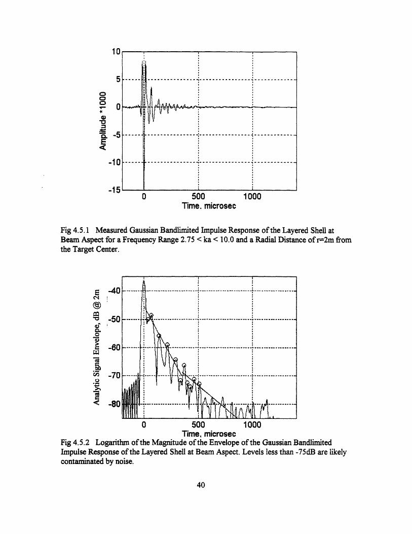
The bandlimited impulse response and logarithm of the magnitude of the analytic
signal representation are shown in Figure 4.5.1 and Fig 4.5.2. Only the first return is
similar to the shell with internal structures only. But after that the signals are much like the
empty shell case. The initial decay rate is 0.071 dB/jisec, which is similar to that of the
25

empty shell. But damping along the shell probably increases the decay rate for t>350jgsec
compared to that of the empty shell. Envelope functions for the different frequency bands
are shown at Figure 4.5.3. The decay rates are calculated from the peak signals greater
than -76dB. They are 0.044 dB/gsec for the low frequency band, 0.061 dB/tsec for the
mid frequency band and 0.052 dB/tsec for the high frequency band. That varying decay
rates depend on frequency indicates that the damping, as well as the elastic process, may
depend on frequency.
The magnitudes of the spectral function of the impulse response are shown in
Figure 4.5.4 and Figure 4.5.5. In the period 350 !tsec to 1200 Iisec, the magnitude of the
spectral function shows maxima around the first and second ring frequencies, (although
the second ring frequency is at 27kHz instead of 30 kHz). This indicates that the radiation
by the induced compressional waves on the shell still has a major effect on the scattering
process. Unlike the internal structures only case, the internal structures in the layered shell
have little influence on the scattering energy even in this later period. But Figure 4.5.5
shows that the second ring frequency dominates the first ring frequency in all frequency
bands. The four rubber block attachments influence the induced compressional waves to
prefer second ring frequency radial motion, due to the quadrant symmetry of the internal
structures.
The damping layer causes scattering from the layered shell to be similar to the
scattering from the empty shell, for t<300pxsec. In this time domain, rings and internal
structures do not store enough energy to contribute to the scattering. But, the four rubber
attachments causes second ring frequency radial motion of the shell to be dominant at later
times. Damping along the shell increases the decay rate at later times to 0.032dB/gsec
which is larger by about a factor of 4 than that of the internalled shell. This effect depends
on frequency.
26

10
5
ooC
-U'
<-
E
0
-5
-10
.1t
0 500 1000Time. microsec
Fig 4.2.1 Measured Gaussian Bandlimited Monostatic Impulse Response of the EmptyShell at Beam Aspect for a Frequency Range 2.75 < ka < 10.0 and a Radial Distance ofr=2m from the Target Center, normalized by the amplitude of the incident wave.
EcsN
P:
e
L
._4c)
. 4
la
-40
-50
-60
-70
-80
0 500 1000Time. microsec
Fig 4.2.2 Logarithm of the Magnitude of the Envelope of the Gaussian BandlimitedImpulse Response of the Empty Shell at Beam Aspect, 2.75 < ka < 10.0 (Envelope is fromFig 4.2. 1).
27

1
0.8
0.6
0.4
0.2
nC 10 20 30 40 50 60
Frequencv. kIz
Fig 4.2.3 Gaussian Bandpass Filters, Low Bandpass Filter, 2.35 < ka < 5.64. MidBandpass Filter, 4.70 < ka < 7.99. High Bandpass Filter, 7.05 < ka <10.34. The dashcurve is the overall Gaussian Filter
28
tf//l l// \ N\ -----------g; ~ */ i -- l- ------- -X ----- -------
-- _ I- -----li--- -- ------VtX. J·------------- -i------ · -------------/,,,.,,,----------
/ I r
..- *~---~--L---L--L-K--
I

(a)
-40
-60
-80E
m@
0.o
.r.C)W._
"a
-40
-60
-80
-40
-60
-80
0 500 1000
(b)
0 500 1000
(C)
0 500Time, microsec
1000
Fig 4.2.4 Logarithm of the Magnitude of the Envelope of the (a) Low FrequencyBandlimited Impulse Response ( 2.35 < ka < 5.64 ), (b) Mid Frequency BandlimitedImpulse Response ( 4.70 < ka < 7.99 ), (c) High Frequency Bandlimited ImpulseResponse ( 7.05 < ka <10.34 ), for Empty Shell at Beam Aspect
29
__________-- --------------- I----------------------
----- /?S r, th-
--I- -L | % s '_ _ _ _ - U------------ - , _............ -- .................
---- 12 -- - - - - - -- -- - - - -- --- - -
I I I I I s _ s #f * `
~1°O~~~ ~(a)- --- ---------------- - ---- -------- =
r '':~ -- - - -r- - - - --------------- --- -------------------- -- -------- --- ---- ---r -- -1 0 .. !!!.! I ..1III . ........ ... ......l ! .... .. i .!'sii II.
-2 ........ .. .....---- .. -----
10- ___ . . .; _. .._ _ : _:: ::: ::: ::- _- .~ . .___.;. ._._... . : -: -- -- ; ----t -----:- ------ ---O' 0 : ' ._-------------- --- ---------------- ............. _ -1-- ----- -- I- - ------- - I- ---------- -T ---------- ------------- ----
10 I I I I
10 15 20 25 30 35 40
A n° (b)^ro'U
10 '1
10-2
1 n-3
10 15 20 25 30 35 40
(b)10 0
1 0
1 0 25 3 54... :- ,:.-:: :: : ~: -~~------: --...-- ......-- ------ -.... ::::::::::::::::::::-r--:
Frequency, kHz
Fig 4.2.5 Magnitude of the Spectral Function of the Bandlimited Impulse Response ofthe Empty Shell at Beam Aspect for the period. (a) 30 sec < t < 800 _spec, (b) 100 sec
< t < 800 psec, (c) 200 psec < t < 800 psec. Broken line shows the Gaussian BandpassFilter response.Filter response.
30
r+ t ff ~Pfff~iT--Y~-~··h CII~r rr-r~r mrr--rr ~ ------------fb-r!!:. E!!=_.=5.=." = = =
....'...-=,, ~== _!_=!~~=~~t::2^_S S .:====':E=!::
'.;_" :_ ! ..____._ _...: '_-: .'-- ... _ .... __..__ _..__: ... __ _.___ ... ___._____.____.- -r .---
-: _- --- : - ---. _- =- -. ~ ------ -.- Z -------t::: ::::,9::::::: :::::-.:::::: :::: .':: :::::: ::::::::::: :::::: ::z:::: ::::::::::........................... T ....... 7A ....... i ..-------------I------------I------------ -r L----------- --- --------- - --------- T ------ ----- -------- -- ---I !I _ I I I _ I1

10
5
00
-oE.
-
0
-5
-10
-150 500
Time. microsec1000
Fig 4.3.1 Measured Gaussian Bandlimited Monostatic Impulse Response of the Shellwith Stiffening Rings at Beam Aspect for a Frequency Range 2.75 < ka < 10.0 and aRadial Distance r=2m from the Target Center.
E
a
.'aw
c;C
V.1.
aa
-40
-50
-60
-70
-80
0 500 1000Time. microsec
Fig 4.3.2 Logarithm of the Magnitude of the Envelope of the Gaussian BandlimitedImpulse Response.of the Shell with Stiffening Rings at Beam Aspect.
31
I !
Ii...................~~·-~~~~f~~~ rC.;Up./t~~~~~~~~~~~r~~~ uk7·Al~~~~~~~~c 1
I I
II~~~~~~~I---------------------I------------------
I
I

(a)
- _- -:- ------------------------
-------------- ~ ------------0 500 1000
(b)
0 500 1000
(c)
0 500 1000Time, microsec
Fig 4.3.3 Logarithm of the Magnitude of the Envelope of the (a) Low FrequencyBandlimited Impulse Response ( 2.35 < ka < 5.64 ), (b) Mid Frequency BandlimitedImpulse Response ( 4.70 < ka < 7.99 ), (c) High Frequency Bandlimited ImpulseResponse ( 7.05 < ka <10.34 ), for Shell with Stiffening Rings at Beam Aspect.
32
-40
-60
-80
-40
-60
-80
E
a@
oc)60.
c)
._
, toi;
,I
V I- .-. - . - -_I, - --- - - - - -
-40
-60
-80

(a)
15 20 25 30 35 40
(b)
15 20 25 30Frequency, kIlz
35 40
Fig 4.3.4 Magnitude of the Spectral Function of the Bandlimited Impulse Response ofthe Shell with Stiffening Rings for the time (a) 30 psec < t < 350 psec, (b) 350 pLsec < t <1200 sec; break line shows the Gaussian Bandpass Filter.
33
100
10'-
10-2
10-31
T------------ r--------C-------- -_ ·sc ' - - - -< .- -- - -
-r------~--------c--------c------r
---------------------------------------------
I - - - l -r=========_=3==_===== _=======__==== ==1====_===__.........................---- ---. . .. .... . . .: -,,,,,,,r,,,,--~--- j---- ---------- *________,--- , ___,________,___-- -__.___
. i , I , - i........ . .......------_-----T----~---r------r--------T. _ _ _ _ _ _ _ _ _ _ _ _ n _ _ _ _ _ _ _ _ , _ _ _ _ _ _ _ _ , _ _ _ _ _ _ _ , _ _ _ _ _ _ _ n _ _i__ _ _ _ _ s _ _ _ _ _ _ _ _ _ _ I _ _ _ _,_ _ _ _ _ _ _ r _ _ _ _ _ i _ _ _ _ __i_ i _._ _ _ _ _ _ _ _ X _ _ _ _ _ _ _ _ _ I _ _ _ _ _ _ I__ _,_ _ _ _ _ _ i__ v _ _ _ _ _ _ _ s _ _ _ _ _ _ _ i
____n_________|___r-------r------T--~~
,,-,,-,,,j .,,,, I,,,, L,, ,,$ ,--, ,,
----- ----| t --------- i . I [ .t---~ -
0
100
10'
10-
1
----- ---f--- ---- - ----------- r --- r----_.rY-_r-c-' _ _ -------- - - - --- - - - - -- - - - - - % % J % %
--- -- ------- c-------c--------
----- ---- ---- -- - - - r - - --I==================C===============r=========.- ........----------. _ ........- . ._ ..______*_.___ __,_ ___ __n_ __------ ----- , ~~ ~~ ~--- -------- -
........ ,~. ..... ~ .....~ . . .. ..... ... .. . . ..: .....
::::::::::::::::::::~::::::::~:::~::t~::z::::::r::::::..... _ .. . .._ ' . . .. ......... & ......... _ _ ~_ _, J '__.* * r J- __---__ ______ L__ ___ ___ ___ J__
......... , .-...... ......... .....--i ....... ----_---__--'_____ T
____s ______ SI i -- i-------:e ----- 7-- - - - - - - - - - - -- - -- T- --- -____L ____F > , _ w t _
________-T________&___----------- -r~~~~Y -is - ~|~ ~ ~ _- _l----L -- I I ;
0
_

(a)
0 15 20 25 30 35 40
(b)------------------- -------------- ;---- ---- -- ---
0 15 20 25 30 35 40
(c)
10 15 20 25 30 35 40Frequency, Idlz
Fig 4.3.5 Magnitude of the Spectral Function of the Bandlimited Impulse Response ofthe Shell with Stiffening Rings at Beam Aspect for the period (a) 30 sec < t < 1200[xsec, (b) 100 [sec < t < 1200 psec, (c) 200 psec < t < 1200 psec
34
. - -- --- - - - - - - - -- - - - - - - - - - - - - - - - - - - - - - - - - - ------
---------------------------- ---------------- ----- ----- - --- -----------------
- - -- -- - - - x- - - - - - - - - - - - - - - - - - - - - - - - - - - - - - -. ;t--- S --- ,--,--,----- L ----- ___L s == c == 5- . ....... -. - ..___ 4___-__ -___: -_:_ __ -____ _-r_- __-__ -___-_- _ --
--------C-------| ------- ~-------I I I
~~~3E~----------,-, ,,,,,E , n z E E,,, 3--------------
-------- -,- ~ ------ , --- ------,,,~,,--- -- -------''~'''''..- -: - _-= - ------- -. ... - ---- -- - -_ --- - --.. i I , . .I
: f I , , , ,
Fi~c--------- ---------
ci-----------------------. . fl M .S .&~~~~~~~~~~~~
10' 1
10'2
10-
1
10'2
10-31
10-1
10 '2
I n-3
- - - -;,--- - ---I;-;; L ;;;;......... _ _ , _: _ ... _ _ _* _ _ ' ' _ _ _ _- _- - -- -. .-------- .- ..--.-.-----.--.----......----- ..-- r---- -- --,,,
----~~--------r----` -t -- ---- ---'
~~~~~~~~~~~~~~~~~~~~~~~~~~~~~~~~~~~~~~,,_,,--- --- ---------- - ------------- >* N-------------- -------- ---------
c�I
I
.

70
60
E
250-o0E
40
E020
·in
i...* II I t I' ' ' : : I
... i . .........
* *. I* ....... : . : . . ;I I I rlr II I I , II I
* I * t - -
In 5 0 25 0 5I * I __ * _ _
.I II I rr I
------- e----^-S------- -----------'-------------- T' ^--
I Ab I I I.4 I ·-- )
----- - ~--- --- -~~- r +-- - - -- - - -- -- -- - -- --- --- -- - -- ----------1T,I I- * * * . I+T~~~ j
F+I i i iii
10 15 20 25 30 35 40Frequency, kHz
Fig 4.4.1 Calculated Natural Modes of the Internal Structure ( There are 62 naturalmodes in the frequency range 10 kHz to 42 kHz )
35

10
5
Co0o0044)
:3
E
0
-5
.10
-150 500
Time. microsec1000
Fig 4.4.2 Measured Gaussian Bandlimited Impulse Response of the Shell with InternalStructure at Beam Aspect for a Frequency Range 2.75 < ka < 10.0 and a Radial Distanceof r=2m from the Target Center.
E
co
"O0
U:;
laoq,
-40
-50
-60
-70
0 500 1000Time. microsec
Fig 4.4.3 Logarithm of the Magnitude of the Envelope of the Gaussian BandlimitedImpulse Response of the Shell with Internal Structure at Beam Aspect.
36
2 IitA
· | - - ~I
I !L
----------------------,,,-- - _-- --- - - -- -,- ..- .--------------..-
I" ..
llIrfll r' - . v - -

0 500 1000
0 500 1000
0 500 1000time(microsec)
Fig 4.4.4 Logarithm of the Magnitude of the Envelope of the (a) Low FrequencyBandlimited Impulse Response ( 2.35 < ka < 5.64 ), (b) Mid Frequency BandlimitedImpulse Response ( 4.70 < ka < 7.99 ), (c) High Frequency Bandlimited ImpulseResponse ( 7.05 < ka <10.34 ), for Shell with Internal Structures at Beam Aspect.
37
-40
-60
-80
-40
-60
-80
-o0
Nol4.C)
-------------------- ----------------- ------
---- i--\~4,-------~------------------------l l l--------- -~~---~---~~~--~-----,~r;,. . . r~~~~~~~~~~~~~~~~~~~~~~~~~~~..... t ..................
-- --------- ----------------- ------------------ ------'' ' -- ~~ I' t'''!t''~ -- E [ E . :

1 nO (a)lU
10 - 1
10-2
l 3
Z : '-1I ---
,_.---[. '. _ _:_ _._
i?_._
10 15 20 25 30 35 40
o (b)----- --.-... ,......-.
....'...------- '.--------- ------- --.---------.----..... -. --------------- --------- -.'----.:--------. .-------- .- .------ -------- . -----I-------- --. +....
10 ' . .. -\ ------- ---------- ----------------- -- ------- '--:-:.:~..:--.:-:-:---- --
Frequency kHz...... , .. , s,.~ - _ _
. . . . .,,- I .d
the Shell with Internal Structures for the period (a) 30 sec <t < 350 sec, (b) 350 sect < 1200 Frsec; break line shows the Gaussian Bandpass Filter
Fig 4.4.5 Magnitude ofthe Spectral Function ofthe Bandlimited Impulse Response ofthe Shell with Internal St5ctures for the period (a) 30 ,sec < t < 350 sec, (b) 350 sec< t < 1200 sec; break line shows the Gaussian Bandpass Filter
38
-- - - - - - - F - - - - - - -J- -- i-------~ -- :1 -~~~~~~~~~~~~~~~~~~~~~~~~~~~~7
---------- ------- - --------- -- ---- ,j---- - !.,,,, -------- l-------- ----------------- ·-------- ·----------- -------- I -------- ·
. _ _ _ ______-________4________--- --- -- --- -- .
--------c-------l ---- - --- ---- -- -- -- - ----------I t I ! .
--,--,-, L--------l-r------ -I-- -- - -- - - - -Ea 3~~~~~~~~~~~~~~~~~~~~~~~~~.........---~-- ';- ...... ' ....... : ...... ...- t .........rr(--c--,, ~----1----------- ----------- ;---- ---- ·'- - - - , - - -._ -e._=_.. I___________- ... _ ._.-:... -s...,_.. _..s.- - , , I ! I I "-
... .,-. ...- 1 ------ -I --------- ..... ~......i...... ...--.--.-
........----- 'c....: ......... :--- ........ 1-----: ..... I.........._ i _ _ _ _ _ _ __ __ - _ill !. I i . I -. . . . . . . _ _ ----- - --. '
ir > i , I i

(a)
___ ___ _,----------------------- - ---------- "- -------------i i ,- ----- -r------- *-~~------ v---r- ---------- -------- -------------------"--r----------- --- ----
i'_ - --- -- 't _- ......---i1= i i; C====~~i r= Li
i~ ~~ ~~ ~~ n~ ~~ ~~ r~ ~~ ~~ - -- -- -n--- -- -r_ ___ __,___ ___ __ ___ r-- -~- @-~~ ~~- w-- --f- -r- . _ _ _ _ _ _ _ _ o _ _ _ - _ _ _ _ _ _ _ _ _ _ _ _I_ _ _ _ _ _ _ _ _ ,L _ _ _ _
, f , , , $ ,~~~~_______________^_______ ________________________v__
15 20 *25 30 35 40
(b)
15 20 25 30 35 40
(c)
15 20 25 30Frequency, ktHz
35 40
Fig 4.4.6 Magnitude of the Spectral Function of the Bandlimited Impulse Response ofthe Shell with Internal Structures at Beam Aspect for the period (a) 30 sec < t < 1400,usec, (b) 100 psec < t < 1400 sec, (c) 200 psec < t < 1400 sec
39
10-1
10-2
10
4n-1lU
10'2
10'31 0
10-1
10'2
10-1 0
-------C-----~---------------------------~ -- - -- - -- - - - - -t------- - ---- -- ------------------------------- ---- ~L--~
---------- E-----,-s_-----L--------------- r--------~---------------------
----- --------- - --- -- C-- --------------- -----------r-------- ------------------------------- '--- ---- r----- '
------------------------ -------------- ---- --- --- --------- ---------- ~--------- -- -
1 n'3
10
5
0
To.001&.1-
0
-5
-10
_190 500 1000
Time. microsec
Fig 4.5.1 Measured Gaussian Bandlimited Impulse Response of the Layered Shell atBeam Aspect for a Frequency Range 2.75 < ka < 10.0 and a Radial Distance of r-2m fromthe Target Center.
E
lao0
7
toC,,U
.2a
0 500 1000Time, microsec
Fig 4.5.2 Logarithm of the Magnitude of the Envelope of the Gaussian BandlimitedImpulse Response of the Layered Shell at Beam Aspect. Levels less than -75dB are likelycontaminated by noise.
40

(a)
-40
-60
-80
E
N@CQ
o
:0.0aC)
._V1.1
-200 0 200 400 600 800 1000 1200
(b)
OI- ...---------.......... ....................:
-ouv r--r--- -- --....- .... . . . . . . i ..
-21
-40
-60
-80
30 0 200 400 600 800 1000 1200
(c)I I , I I I
t . . . . . .f\ I , : : -
, . I , . .
I I , -
-200 0 200 400 600 800 1000 1200Time, microsec
Fig 4.5.3 Logarithm of the Magnitude of the Envelope of the (a) Low FrequencyBandlimited Impulse Response ( 2.35 < ka < 5.64 ), (b) Mid Frequency BandlimitedImpulse Response ( 4.70 < ka < 7.99 ), (c) High Frequency Bandlimited ImpulseResponse ( 7.05 < ka <10.34 ), for Layered Shell at Beam Aspect.
41
'-----.-r.---------- :------,-------------'- ' , -- . ......
....' ....
I I I - -- , , ,-;: : :. . . .
. * .. . . .
. . . .
i

(a)'- ...... ,.I ...--- ·-~-41 i ......
- " -.i.....--- _8-----r - .. .
… *1--- =.-------~=========== ====
---..,--~ - r .....-------- "--E-'=--- ·
|. ._ _ !_ 5 _ _.... , .... : .....
= = =-- = = = = = ==- ' r......___ _ _-----------
--------- -----
: _:------n
!-"___, ------ ---------
0 15 20 25 30 35 40
(b)
0 15 20 25 30 35 40Frequency, kIdIz
Fig 4.5.4 Magnitude of the Spectral Function of the Bandlimited Impulse Response ofthe Layered Shell for the period (a) 30 sec < t < 350 isec, (b) 350 sec < t < 1200
.sec; break line shows the Gaussian Bandpass Filter
42
10'
10-'
10-31
I d
10 -°
10-2
10-31
_ .…. …A...· ....- . ........ .---- 3
. . . .. . .J,, . . ' J _
-.... . .. ' .. .... ..... .. ...' .---i___!____"______ if i ! _
= ================ == .... j_' ........ '. ...... ' ..---.---- r_------,___....... I 4 . ..-.........-..- ;---- ----.... . , . . . ....a . . ... .....~... .-- . ...
....... 4 ...... :- ....... ~----:- ...... ....t....-----:-:=-====-i=:=:- =:b=:=:====== ==========:==
ii-=__ =- -=__ -_______.________. .___=-____________._.. ___ J ..._ .. .,_~ ._.,. . ._. _ _'. ~ -. I ___J________ ---......-- ,--,t.....-~-,-~r-~.t~-~~--~-----t ~~~,'~
. . . . .-: -,. . . . .
___ · ·
· i ! mp I ii I I I I i~ ~~~~~~~~~~~~~~~~~~~~~~~~~~~~~~~~~~~~~~~~~~~~~~~~~~~~~I
I

(a)
15 20 25 30 35 40
(b)
15 20 25 30 35 40
(C)
20 25 30 35 40Frequency, kz
Fig 4.5.5 Magnitude of the Spectral Function of the Bandlimited Impulse Response of theLayered Shell at Beam Aspect for the period of (a) 30 gsec < t < 1200 gsec, (b) 100 gsec< t < 1200 gsec, (c) 200 gsec < t < 1200 gsec
43
0
10- 1
10 -2
10 '3
1
10 '1
10 -2
10 -3
1i
4n1
-2
10-2
I1 -3
l1
0
0 15
r---~-r---L,--~------------------------------------- L------------------ ;---------------------------- --~-- -- ---- - ------- - -- -- -- -- -- --
---- ,--I,,,,,,, i=~=== ------------- r--,-,-~------~- ----------- -- l- -- ---- L --- - - - -- - -- L -,--,-- -- -- ~ -- -- , ,
--------- -'----- ----------------------·--- ----
--------------,----------------,----------
-------i--------- -------i---
iI- - - - - - - - - - - - - - -- --=
---------- ------- ;

5. Conclusion
The initial or geometric returns of the shells at beam aspect are -3 8.7dB re. r=2m
for the empty shell, -38.5dB for the ring stiffened shell, -36.7dB for the internalled shell
and -36.4dB for the layered shell, or about -37.6dB±+1. dB for all cases. These results are
quite different from the simplified lumped-system model analysis, and shows that the
distributed rings can not be modeled by a simple uniform extra mass on the shell. Because
of the small range (1. IdB ), the role of internal structures and other complexities in the
geometric return can be neglected.
The decay rates obtained from the beam aspect backscattering data are
summarized in Table 5.1. First and subsequent decay rates are calculated for each
bandwidth: total frequency band 12 - 42 kHz, low frequency band 10 - 24 kHz, mid
frequency band 20 - 34 kHz, and high frequency band 30 - 44 kHz. The time that
separates the first and subsequent decay rates are 350 Usec for the total frequency band,
450 gsec for the low frequency band, 350 psec for the mid frequency band and 250 gsec
for the high frequency band. These times are calculated from the round trip group delay
through the shortest bay of the shell by the flexural wave in that frequency band. In the
empty shell case, the round trip travel time by the flexural wave through the entire shell is
around 1500 .tsec, for which data are not available. Therefore, only the first decay rates
are tabulated for the empty shell.
For the total frequency band, the first decay rate for the empty shell is higher than
those for the shell with stiffening rings and the shell with internal structures only, and
about the same as for the layered shell. The first decay rates for the empty shell do not
change with frequency. The shell with stiffening rings and the shell with internal structures
44

have similar first decay rates. The added internal structures provide energy storage and the
decay rates are less than the empty shell case, especially at low frequency where the decay
rates for both are much smaller than the empty shell case. The decay rates are larger at
high frequency. The layered shell is much like the empty shell, except that it has a little
larger first decay rate because of damping on the shell. And the layered shell has different
decay rates as a function of frequency.
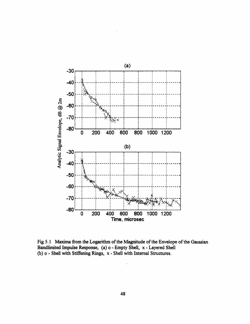
Fig 5.1 compares the maxima from the envelope function for each shell. The empty
shell and the layered shell have very similar decay patterns. Also, the shell with stiffening
rings and the shell with internal structures have similar decay patterns. The influence of the
rings and internal structures are best seen after 350 gsec; for the ringed shell and
internalled shell, the decay is measureable to 1400 gsec, but for the layered shell it is quite
weak due to the layer.
The induced compressional waves, which circumnavigate the shell, are the major
source of the scattering process for the empty shell. From Fourier analysis, the empty shell
radiates elastically mostly through the first and second ring frequencies. The measured
major scattering frequencies are 16 kHz and 32 kHz. These are very close to the
calculated first and second ring frequencies, 15kHz and 30kHz. The shell with the
stiffening rings also has the same major elastic scattering frequencies as the empty shell.
But the analysis in the later time period shows that these frequencies are shifted to higher
frequencies by about 2kHz.
In all shells, the major source of the scattering is the induced compressional waves
on the shell for the early time. But, for all but the empty shell, the stiffening rings store
energy, and become a major source of scattering, and they radiate preferentially at the ring
frequencies. In the shell with internal structures(internalled and layered), the attachments
of the four rubber blocks influence radial ring motion to prefer the second ring frequency.
45

But late in time(after 200 gsec), the internal structures of the internalled shell only
influence the scattering and there is no dominant scattering frequency. The internal
structures of the layered shell however do not interact much with the shell even at the later
time. Therefore, there is still preferential scattering through first and second ring
frequencies. The damping along the shell reduces energy storage in the rings and internal
structures, so they can not contibute as much to the radiation at a later time.
46

Table 5.1 Decay Rates (dB/psec) from the Logarithm of the Magnitude of the Envelopeof the Gaussian Bandlimited Impulse Response. Where there are two entries, the top oneis for the initial decay, the bottom for the subsequent decay. ( Subsequent decay rates areobtained after 350 psec for 12 - 42 kHz band, after 450 ,isec for 10-24 kHz band, after350 gisec for 20 - 34 kHz and after 250 psec for 30 - 44 kHz.) Missing subsequent decayrates are caused by concern for noise contamination.
47
Bandpass Filter12kHz- 10kHz- 20kHz- 30kHz-
42kHz 24kHz 34kHz 44kHzEmpty Shell 0.064 0.065 0.065 0.063
Shell with 0.051 0.030 0.056 0.085Stiffened Rings 0.011 0.0032 0.0066 0.0114
Shell with 0.045 0.032 0.078 0.076Internal Structures 0.0081 0.0011 0.0108 0.0087
Layered Shell 0.071 0.044 0.061 0.0520.032
-30
-40
-50
-60
-70
-80
-30
-40
-50
-60
-70
-80
(a)
I '.~ r - - - -- - - - - -- I-1\ I I I I
--~-~1''-I''''''' r------r'-'--- ---------- -------I . ' I I I ,,
0 200 400 600 800 1000 12I0I : ^,l . | 8 @ . I
(b)i I i i i i
.-...... ----.------------- ------ -------
~ ..... ~~~~~~,___· i i * F . . . .I i . .~ I I I i-- - - -- - --
----- _-- --- -- 5-- -- .----- 7V
0 200 400 600 800 1000 1200
Time , microsec.n . . . .. n . . .. . . . .Q'-h''l''' 200--''''l' 40Q 60 8001000100--
t I I r(bl~ : : -:
I ._X____-------r----r-----i-------------------.l . . . ..\ . . .I . .
I n . . .I n X . i-------- ---- -- w_ __ n_ _
. w.st . | '
. I . . * I
0 200 400 600 800 1000 1200Time, microsec
Fig 5.1 Maxima from the Logarithm of the Magnitude of the Envelope of the GaussianBandlimited Impulse Response, (a) o - Empty Shell, x - Layered Shell(b) o - Shell with Stiffening Rings, x - Shell with Internal Structures.
48
E
m
>ao
.-aco
.2M

Table of Figures
2.1 The Design Configulation of the Empty Shell Model and the location of theRing Stiffeners ... ....................................................... 9
2.2 The Configulation of the Internal Structures ........................................ 9.................3.1 Natural frequency of the rubber block with derlin and stainless steel mass inside.
Lowest natural modeshape for the rubber block with derlin and stainles steelm ass inside ........... .. ................ ................ ........................................................12
3.2 Diagram for Cylinderical Shell with Stiffening Rings. Cylindrical Shell withInternal Structures M odel ........................................................... 13
3.3 Gaussian Bandpass Filter (up), mean 27.3 kHz and standard deviation 13.2 kHz.Gaussian bandpass filter Impulse Response (Down), 6 dB down at Band Edgesof the Frequency Range 2.75 < ka < 11.7 .......................................................... 14
3.4 Magnitude of the Impedence Function for the three shell models ......................... 153.5 Gaussian bandlimited impulse response function of three shell models ................. 163.6 Bandlimited impulse response functions with increasing resonance frequency of
the internal structure. Maximum return in impulse response as the resonancefrequency changes .......................................................... 17
4.2.1 Measured Gaussian Bandlimited Monostatic Impulse Response of the EmptyShell at Beam Aspect for a Frequency Range 2.75 < ka < 10.0 and a RadialDistance of r=2m from the Target Center ................................................ 27
4.2.2 Logarithm of the Magnitude of the Envelope of the Gaussian BandlimitedImpulse Response of the Empty Shell at Beam Aspect, 2.75 < ka < 10.0 ......... 27
4.2.3 Gaussian Bandpass Filters, Low Bandpass Filter, 2.35 < ka < 5.64. MidBandpass Filter, 4.70 < ka < 7.99. High Bandpass Filter, 7.05 < ka<10.34 ...... 28
4.2.4 Logarithm of the Magnitude of the Envelope of the (a) Low FrequencyBandlimited Impulse Response ( 2.35 < ka < 5.64 ), (b) Mid FrequencyBandlimited Impulse Response ( 4.70 < ka < 7.99 ), (c) High FrequencyBandlimited Impulse Response ( 7.05 < ka <10.34 ), for Empty Shell at BeamA spect ......................................................... 29
4.2.5 Magnitude of the Spectral Function of the Bandlimited Impulse Response ofthe Empty Shell at Beam Aspect for the period. (a) 30 jlsec < t < 800 gsec,(b) 100 gsec < t < 800 gsec, (c) 200 lisec < t < 800 gsec ............................... 30
4.3.1 Measured Gaussian Bandlimited Monostatic Impulse Response of the Shellwith Stiffening Rings at Beam Aspect for a Frequency Range 2.75 < ka < 10.0and a Radial Distance r=2m from the Target Center ......... ..................... 31
4.3.2 Logarithm of the Magnitude of the Envelope of the Gaussian BandlimitedImpulse Response of the Shell with Stiffening Rings at Beam Aspect ....... 31.. 3 1
4.3.3 Logarithm of the Magnitude of the Envelope of the (a) Low FrequencyBandlimited Impulse Response ( 2.35 < ka < 5.64 ), (b) Mid FrequencyBandlimited Impulse Response ( 4.70 < ka < 7.99 ), (c) High FrequencyBandlimited Impulse Response ( 7.05 < ka <10.34 ), for Shell with StiffeningRings at Beam Aspect ................... 3............. ................... 2............ 32
49

4.3.4 Magnitude of the Spectral Function of the Bandlimited Impulse Responseof the Shell with Stiffening Rings for the time (a) 30 psec < t < 350 sec,(b) 350 psec < t < 1200 sec ................................... ..................... 33
4.3.5 Magnitude of the Spectral Function of the Bandlimited Impulse Responseof the Shell with Stiffening Rings at Beam Aspect for the period(a) 30 [psec < t < 1200 psec, (b) 100 psec < t < 1200 psec,(c) 200 psec < t < 1200 psec ......................................................... 34
4.4.1 Calculated Natural Modes of the Internal Structure ......................................... 354.4.2 Measured Gaussian Bandlimited Impulse Response of the Shell with Internal
Structure at Beam Aspect for a Frequency Range 2.75 < ka < 10.0 and aRadial Distance of r=2m from the Target Center ........... .......................... 36
4.4.3 Logarithm of the Magnitude of the Envelope of the Gaussian BandlimitedImpulse Response of the Shell with Internal Structure at Beam Aspect ............. 36
4.4.4 Logarithm of the Magnitude of the Envelope of the (a) Low FrequencyBandlimited Impulse Response ( 2.35 < ka < 5.64 ), (b) Mid FrequencyBandlimited Impulse Response ( 4.70 < ka < 7.99), (c) High FrequencyBandlimited Impulse Response ( 7.05 < ka <10.34 ), for Shell with InternalStructures at Beam Aspect ............. ...................................... 37
4.4.5 Magnitude of the Spectral Function of the Bandlimited Impulse Response ofthe Shell with Internal Structures for the period (a) 30 psec < t < 350 Psec,(b) 350 psec < t < 1200 sec ........................................................ .............. 38
4.4.6 Magnitude of the Spectral Function of the Bandlimited Impulse Response ofthe Shell with Internal Structures at Beam Aspect for the period(a) 30 gsec < t < 1400 gsec, (b) 100 psec < t < 1400 isec,(c) 200 j.sec < t < 1400 gsec ................................................................ ... 39
4.5.1 Measured Gaussian Bandlimited Impulse Response of the Layered Shell atBeam Aspect for a Frequency Range 2.75 < ka < 10.0 and a Radial Distanceof r=2m from the Target Center .............................. .................................... 40
4.5.2 Logarithm of the Magnitude of the Envelope of the Gaussian BandlimitedImpulse Response of the Layered Shell at Beam Aspect .................................. 40
4.5.3 Logarithm of the Magnitude of the Envelope of the (a) Low FrequencyBandlimited Impulse Response ( 2.35 < ka < 5.64 ), (b) Mid FrequencyBandlimited Impulse Response ( 4.70 < ka < 7.99 ), (c) High FrequencyBandlimited Impulse Response ( 7.05 < ka <10.34 ), for Layered Shellat Beam Aspect ......................................................... 41
4.5.4 Magnitude of the Spectral Function of the Bandlimited Impulse Responseof the Layered Shell for the period (a) 30 gsec<t<350 sec,(b) 350 psec<t<1200 psec ........................................ ................ 42
4.5.5 Magnitude of the Spectral Function of the Bandlimited Impulse Responseof the Layered Shell at Beam Aspect for the period of(a) 30 gsec < t < 1200 gsec, (b) 100 sec < t < 1200 sec,(c) 200 gsec < t < 1200 gsec ................................... ..................... 43
5.1 Maxima from the Logarithm of the Magnitude of the Envelope of the GaussianBandlimited Impulse Response ....................................................................... 48
50

Table of Tables
2.1 Summary of M odel Design Parameters ................................................................. 85.1 Decay Rates (dB/!lsec) from the Logarithm of the Magnitude of the Envelope
of the Gaussian Bandlimited Impulse Response ............................ ........................ 47
51

References
[1] M. C. Junger, and D. Feit, Sound, Structures, and Their Interaction, (MIT Press,Cambridge, MA 1986)
[2] K. L. Williams and P. L. Marston, " Axial Focused (Glory) Scattering Due to SurfaceWaves Generated on Spheres: Model and Experimental Confirmation Using TungstenCarbide Spheres", J. Acoust. Soc. Am., 78 (2), 772-728 (1985).
[3] S. G. Kargl and P. L. Marston, "Observation and Modeling of the Backscattering ofShort Tone Bursts from a Spherical Shell: Laml Wave Echoes, Glory, and AxialReverberations", J. Acoust. Soc. Am., 85 (3), 1014-1028 (1989).
[4] L. B. Felson, J. M. Ho, and I. T. Lu, "Three Dimensional Green's Function for Fluid-Loaded This Elastic Cylindrical Shell: Formulation and Solution", J. Acoust. Soc.Am., 87 (2), 543-553 (1990).
[5] L. B. Felson, J. M. Ho, and I. T. Lu, "Three Dimensional Green's Function for Fluid-Loaded This Elastic Cylindrical Shell: Alternative Representations and Ray AcousticForms", J. Acoust. Soc. Am., 87 (2) 554-569 (1990).
[6] L. B. Felson, J. M. Ho, and I. T. Lu, "Erratum: Three Dimensional Green's Functionfor Fluid-Loaded This Elastic Cylindrical Shell: Alternative Representations and RayAcoustic Forms", J. Acoust. Soc. Am., 89 (3) 1463-1464 (1991).
[7] F. Leon, F. Lecroq, D. Decultot, and G. Maze, "Scattering of an Obliquely IncidentAcoustic Wave by an Infinite Hollow Cylindrical Shell", 91 (3), 1388-1397 (1992).
[8] Y. P. Guo, "Sound Scattering from an Internally Loaded Cylindrical Shell", J. Acoust.Soc. Am., 91, 926-938 (1992).
[9] Y. P. Guo, "Sound Scattering from Cylindrical Shells with Internal Elastic Plates", J.Acoust. Soc. Am., 93 (4), 1936-1946 (1993).
[10] C. N. Corrado Jr, "Mid-Frequency Acoustic Backscattering From Finite CylindricalShells and The Influence of Helical Membrane Waves", Ph.D Thesis, January 1993.
[11] I. Dyer and M. Conti, Memorandum dated 25 June, 1990, Subject: Scale ModelExperiments on an Internally Loaded Cylinder.
[12] Personal Meeting with I. Dyer during January 1995.[13] P. M. Morse nad K. U. Ingard, TheoreticalAcoustics, (Princeton University Press,
Princeton, New Jersey, 1968).
52

Appendix A
Lumped model analysis for infinite cylinders
Radiation from an infinitely long cylinder has been studied by Morse[ 13]. Theequations which governs the radiation pressure field is the Helmholz Equation.
V 2p + k 2p = O (1)Equation (1) in cylindrical coordinate is
Ir + I + = (2)
We can solve Equation (2) by using the method of seperation of variables. First,we assume the solution of Equation (2) in the form
p = R(r)((O)Z(z)e - ' (3)
where R is a function of r alone, 1 is a function of 0 alone and Z is a function of z alone.If (3) is introduced into equation (2), we get three ordinary differential equations
dZ + k2Z = (4)
d2 + m2 = (5)do 2 i+d ( R (k2- (6)rdr dr - r
where m must be an integer for the solution to be continuous at b =0=27c and,
k2+ k2 = k.
Equation (4), (5) and (6) all have analytic solutions in the form ofZkc _-iktzzZ e' e-iZ
P ao cos m, sin mqR c Jm(krr),Nm(krr)
We assume the cylinder as infinitely long so that there is no z dependence in thepressure field. Now we will only consider cos 0 as the angular dependence. Therefore,k, = 0 and m=l. So, the pressure field solution is
p = Acos4J,(kr)+ iN(kr)]e'iand when r-a
p = A cos 4J(ka) + iN(ka)]e'= A cos OH,(ka)e't
where, H(ka) is the Hankel function of first kind.From the pressure field at r=a, we get the reaction force per unit length F in the x
direction2fx
F= Jpacos tdo = AacHl(ka)e '
0
53

From the relationship between the particle velocity and pressure1 >
iA cos4H 2(ka)- Ho(ka)]e'2pc
the velocity in the x direction is
U= MiA [H2(ka)-H.(ka)]e2p
and the impedence function is
F = i2pc H,(ka)U Ho(ka)- H,(ka)
The impedence function can be rewritten as
Z = -ica,.d + Rrd
Mrad = pm2pI Im(f (ka))ka
R,ad = apc Re(f(ka))
f(ka)= 2i H(ka)Ho(ka)- H2(ka)
where M,ad is known as radiation mass or added mass and Rrad as radiation
damping.
The impedence functions for the three different shell models which shown inFigure 3.2 are
Z,., =-i OM + RdZempy = i i + RradM = rad +Mshell
Z,,,ring = -i + Rad
M = Mad + MS,h, + Mg
z - i [-M- i,t(Rad + R) + KsIl- o 2Ms-i ,R + K.]-[iR- Kj]2Zmteal - o 2M -ilR 8 +Ks
and each K, and R, are given by
K,= = O
Ms
.1K,
The impedence functions are derived previously from the radiation pressure field.From the ratio between radiation pressure field and incident pressure field, the impedencefunction can be expressed as,
54
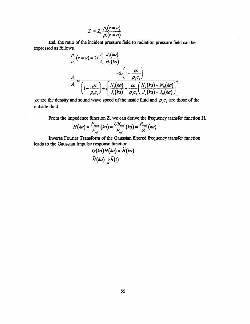
Z = Zp (r =a)pr(r = a)
and, the ratio of the incident pressure field to radiation pressure field can beexpressed as follows.
4 A,(ka)' (r = a)= 2 A J,(ka)Pr A, H,(ka)
-2,,- pc )Ar 2{1 DOCoA, 1- p c N +i (ka) N2(ka)- N.(ka)
pOco) k p J, (ka) (ka)pc are the density and sound wave speed of the inside fluid and poCo are those of the
outside fluid.
From the impedence function Z, we can derive the frequency transfer function H.
H(ka) F (ka) Uad (ka)= R d (2a)F,. Ff Z
Inverse Fourier Transform of the Gaussian filtered frequency transfer functionleads to the Gaussian Impulse response function.
G(ka)H(ka)= H(ka)
HI(ka) -*h (t)
55
Appendix B
Natural modes of internal structures in the cylindrical shell
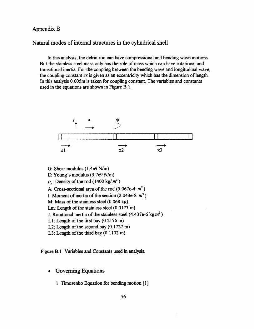
In this analysis, the delrin rod can have compressional and bending wave motions.But the stainless steel mass only has the role of mass which can have rotational andtransitional inertia. For the coupling between the bending wave and longitudinal wave,the coupling constant es is given as an eccentricity which has the dimension of length.In this analysis 0.005m is taken for coupling constant. The variables and constantsused in the equations are shown in Figure B. 1.
y u (P
T D
II i l II ! i
xl x2 x3
G: Shear modulus (1.4e9 N/m)E: Young's modulus (3.7e9 N/m)p, : Density of the rod (1400 kg/m3 )
A: Cross-sectional area of the rod (5.067e-4 m2 )I: Moment of inertia of the section (2.043e-8 m4 )
M: Mass of the stainless steel (0.068 kg)Lm: Length of the stainless steel (0.0173 m)
J: Rotational inertia of the stainless steel (4.437e-6 kg m2 )
L1: Length of the first bay (0.2176 m)L2: Length of the second bay (0.1727 m)L3: Length of the third bay (0.1102 m)
Figure B. 1 Variables and Constants used in analysis.
Governing Equations
1 Timosenko Equation for bending motion [1]
56
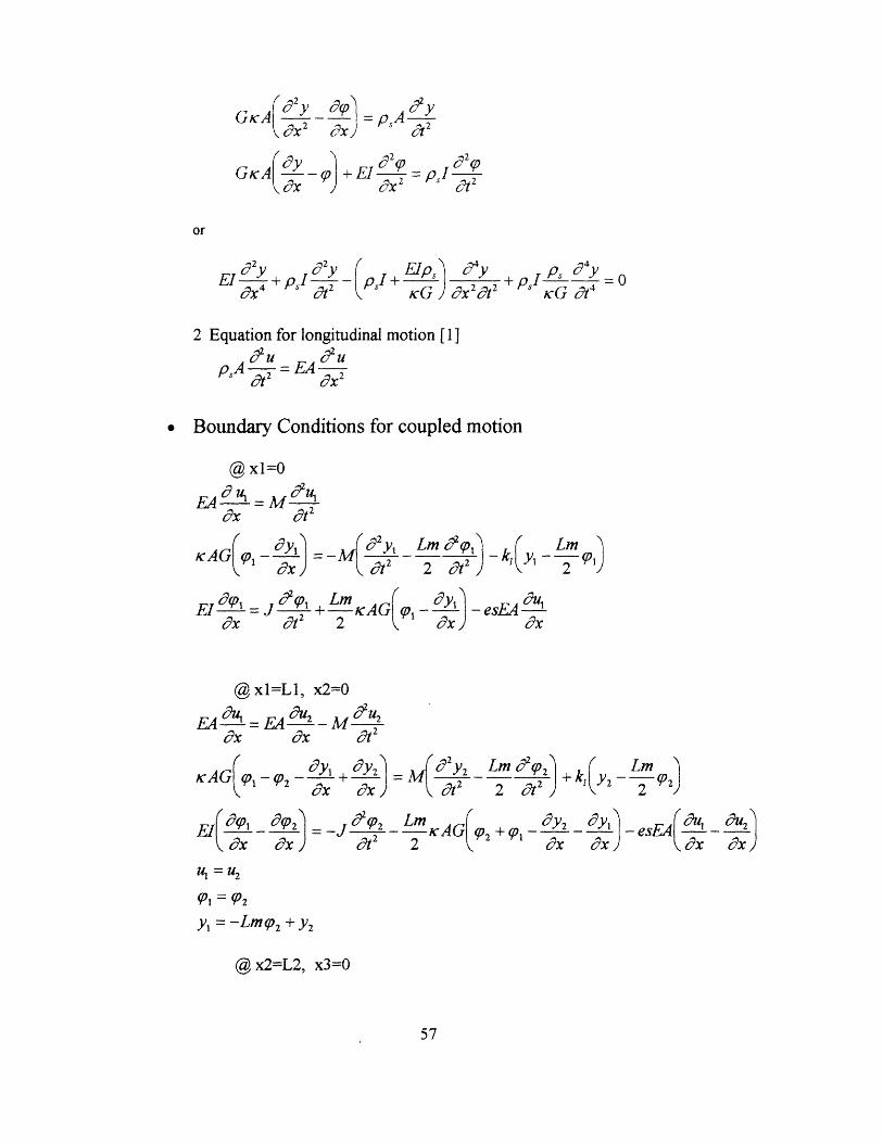
GA oxd2y_
GKAQO$
d 2y
+ EId 2OX 2
P 2p= pI --t2
or
'2y P 2y ( E .6yEI T + pI i -ps + G x2 psI - =0 4 c1 KG dX2 t cG 0d 4
2 Equation for longitudinal motion [1]
pA =EA
Boundary Conditions for coupled motion
@ xl=0
cx
AG(joi -
dt2
d2 yl_
d t2Lm td p,
2 a2
Lm )2 T-I
+ - KAG q-2K dx j
@xl=L1, x2=0~2EA MO2
dX at2
- (_2 + d9x OI
- 2 Y2 Lm fd2(2)-7 2 2 a2) +k, Lm2 )Y2 -- 2
El a10" d dx)
- LmAG( q2 +Q) dx d-es2 dx dx eY x
u = U2
= 02
Y1 = -Lm 2 + Y2
@x2=L2, x3=0
57
EI' 1 =Rx
- esEA udx
E4 du, -dX
KAG(p1
-k, Y -
= -

EA du _ M u3
- (P3 eY2 + OYxo3x ox
Lm 3 2
Lm2 AG9 3 + 9P2_ y 3 eY2
?x ox- esEA( &u02
ox
Y2 = -LmP3 + Y3
@,x3=L3
EA dU3 -M d U3
ox dt2
KAG((031- x3=M +~y, Lmd2(3)at2 2 d, )
k + Lm-J d- 2 KAGp 3 - xY3 - esEA 3
dx OEx
Dispersion relations of the bending wave number 3 and frequency o
El 4+ (I + Esp, ) I 2p2+GK j
21 :I (-b+ b2-4ac)
gl2 :(-b -xb2-4ac)
58
EA4 -- 2 =
xKAG
KAG jO 2
= _j 2p3
+kI(y3
U2 = U3
KLm -2 P3)
ps GP 04 psA o2= 0GK
EtO'3