Embed Size (px)
Citation preview

Sound controlled Fire Detector
By
Meng Gao
Yihao Zhang
Xinrui Zhu
Final Report for ECE 445, Senior Design, Spring 2016
TA: Luke Wendt
02 May 2016
Project No. 67

ii
Abstract
Sound controlled Fire Detector is a combination of regular fire detector and speech
recognition module so that user can stop the alarm by simply shouting the keyword. Whenever
the fire detector notices there’s probably a fire hazard, it will activate the micro-controller and
the micro-controller will control the alarm according to the signal from fire detector and the
speech recognition. The speech recognition program must collect speech from microphone and
extract its features and then compare them with the labeled sample we stored in the library to
determine whether the speech contain the keyword “cooking”. Because of the limited time, we
only implemented clap pattern recognition on micro-controller, and speech recognition is solely
done in Matlab.

iii
Contents
1. Introduction ................................................................................................................................ 1
1.1 Objectives ......................................................................................................................... 1
1.2 System Overview .............................................................................................................. 2
2 Design ........................................................................................................................................... 3
2.1 Microphone and Low Pass Filter ........................................................................................... 3
2.2 Power .................................................................................................................................... 6
2.2.1 Power: 3.3 V .................................................................................................................... 6
2.2.2 Power: 5 V ....................................................................................................................... 7
2.2.3 Power: Virtual Ground .................................................................................................... 8
2.3 Microcontroller ..................................................................................................................... 8
2.4 SOFTWARE (Matlab simulation) .......................................................................................... 10
2.4.1 Dynamic Time Warping ................................................................................................ 11
2.4.2 Mel-frequency Cepstrum Coefficients ......................................................................... 11
2.4.3 Data Training ................................................................................................................ 13
3. Design Verification .................................................................................................................... 14
3.1 Low Pass Filter ..................................................................................................................... 14
3.2 Power .................................................................................................................................. 14
3.3 Power Budget ...................................................................................................................... 15
3.4 FFT ....................................................................................................................................... 15
4. Costs .......................................................................................................................................... 17
4.1 Parts ..................................................................................................................................... 17
4.2 Labor .................................................................................................................................... 18
4.3 Grand Total .......................................................................................................................... 18
5. Conclusion ................................................................................................................................. 19
5.1 Accomplishments ................................................................................................................ 19
5.2 Uncertainties ....................................................................................................................... 19
5.3 Ethical considerations ......................................................................................................... 19
5.4 Future work ......................................................................................................................... 20
References .................................................................................................................................... 21
Appendix A Requirement and Verification Table ................................................................... 22

iv
High Level Requirements and Alternative Plans ....................................................................... 22
Table of Requirements and Verification* ................................................................................. 22
Appendix B Matlab simulation Result ................................................................................... 27
Noise analysis result Cooking analysis result .................................................... 27

1
1. Introduction
Almost all of us encounter false fire alarms at some point in our life. Although many
modern fire alarms have the ability to mute temporarily with a push of button, the physical
location of the smoke detector makes it difficult to do so. At the same time, voice controlled
products are entering markets and gaining popularity in recent years. These products, such as
Android phones and Amazon Echo, can be activated by keyword such as “OK Google”, “Alexa”
or “Amazon”.
Therefore, we want to build a sound controlled fire alarm that be easily turned off by
shouting the keyword "cooking" when false alarm happens. In specific, we plan to use many
different human versions of “cooking” as the training data; the processor will find and store the
Mel-Frequency Cepstral Coefficients (MFCCs) for the training word. Then once the alarm is
triggered, the core will be turned on and actively listens for the keyword, finding the MFCCs for
what it hears, and comparing with the stored MFCCs. If the mean square error is below a
threshold, the core will stop the alarm. In additional, we also use Dynamic Time Warping (DTW)
to improve our detection accuracy.
The goal of this project is to create a smoke detector that can suppress its alarm upon
detecting a preset pattern of sound. Ideally, we want to react to a keyword phrase, such as
“COOKING!”, but more practically, given our experience, time, and hardware limitation, is to
detect a clap pattern.
1.1 Objectives
Goals and benefits:
Allow false fire alarms to be safely turned off by shouting the keyword "cooking"
Prevent unnecessary interruption to everyday activities such as cooking
Maintain sufficient warning against possible fire hazard.
Functions and features:
Sense environment condition relating to fire, specifically, Carbon Monoxide
concentration.
Activate alarm and power on microcontroller if fire hazard is detected.
Capture audio if alarm is triggered
2
Implement algorithm to recognize keyword by feature extraction using Mel-Frequency
Cepstral Coefficients
Process audio data in real time using our algorithm and check if there is a match to the
keyword
Pause the alarm if keyword is matched and if it is safe to do so
1.2 System Overview
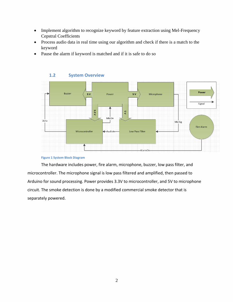
Figure 1 System Block Diagram
The hardware includes power, fire alarm, microphone, buzzer, low pass filter, and
microcontroller. The microphone signal is low pass filtered and amplified, then passed to
Arduino for sound processing. Power provides 3.3V to microcontroller, and 5V to microphone
circuit. The smoke detection is done by a modified commercial smoke detector that is
separately powered.

3
2 Design
2.1 Microphone and Low Pass Filter
Figure 2 schematic for microphone and low pass filter
The microphone circuit uses an Omni-directional microphone. The microphone output is
low pass filtered and amplified through the low pass filter, and then passed to the
microcontroller. The filter assumes that signals above 2500Hz are noise, and we are only
concerned about signals lower than 1000Hz. output from this circuit is amplified to 0 to 5 volt
so that it can take advantage of the full range of the microcontroller.
Initially, we planned to implement a second order low pass filter, and software can do
additional filtering if needed. However, later we discover that although the second order filter
satisfied the 3dB gain requirement, it is unsuitable for our application. For our application, it is
expected that we will have an alarm tone that is so loud that it may saturate the microphone
output. Therefore we revised the design and replaced it with a sixth order Butterworth low pass
filter to achieve better noise suppression. Figure 3 shows a comparison between the frequency

4
responses from a second order low pass filter to a sixth order low pass filter (assuming that the
gain for both filters are 200).
The transfer function for each stage of the filter can be written as
𝑯(𝒇) =−𝑲
(𝒇
𝑭𝑺𝑭 × 𝒇𝒄)𝟐 +
𝟏𝑸
𝒋𝒇𝑭𝑺𝑭 × 𝒇𝒄
+ 𝟏
(1)
Where
𝑲 =−𝑹𝟐
𝑹𝟏
(2)
𝑭𝑺𝑭 × 𝒇𝒄 =𝟏
𝟐𝝅√𝑹𝟐𝑹𝟑𝑪𝟏𝑪𝟐
(3)
𝑸 =√𝑹𝟐𝑹𝟑𝑪𝟏𝑪𝟐
𝑹𝟑𝑪𝟏 + 𝑹𝟐𝑪𝟏 + 𝑹𝟑𝑪𝟏(−𝑲)
(4)
Plugging in the values from the design, we can find the transfer function for each stage
of the filter, and the overall filter:
𝑯𝟏(𝒔) ≈−𝟑𝟕𝟗𝟐𝟔𝟏𝟗𝟓𝟔
𝒔𝟐 + 𝟏𝟏𝟗𝟔𝟏𝒔 + 𝟑𝟕𝟗𝟐𝟔𝟏𝟗𝟔
(5)
𝑯𝟐(𝒔) ≈−𝟑𝟔𝟎𝟕𝟓𝟎𝟑𝟔𝟏
𝒔𝟐 + 𝟖𝟓𝟐𝟒𝒔 + 𝟑𝟔𝟎𝟕𝟓𝟎𝟑𝟔
(6)
𝑯𝟑(𝒔) ≈−𝟕𝟖𝟐𝟔𝟏𝟗𝟓𝟖
𝒔𝟐 + 𝟑𝟐𝟕𝟒𝒔 + 𝟑𝟗𝟗𝟔𝟑𝟓𝟓𝟑
(7)
𝑯(𝒔) = 𝑯𝟏(𝒔)𝑯𝟐(𝒔)𝑯𝟑(𝒔)
(8)
Where 𝑠 = 𝑗2𝜋𝑓. The cutoff frequency of this filter is at 956 Hz, and overall gain is 200
(46 dB).

5
Figure 3 Second order filter compared against third order filter

6
2.2 Power
2.2.1 Power: 3.3 V
Figure 4 schematic for 3.3V power
The 3.3 V power should supply voltage to the microcontroller. The output voltage is
given as:
𝑉𝑜𝑢𝑡 = 1.25 × (1 +𝑅2
𝑅1)
(9)
𝑉𝑜𝑢𝑡 ≈ 1.25 × (1 +200
120) = 3.3𝑉
(10)
7
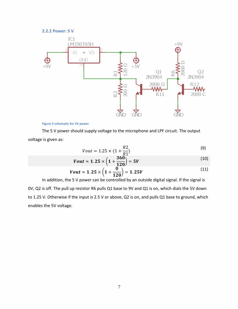
2.2.2 Power: 5 V
Figure 5 schematic for 5V power
The 5 V power should supply voltage to the microphone and LPF circuit. The output
voltage is given as:
𝑉𝑜𝑢𝑡 = 1.25 × (1 +𝑅2
𝑅1)
(9)
𝑽𝒐𝒖𝒕 ≈ 𝟏. 𝟐𝟓 × (𝟏 +𝟑𝟔𝟎
𝟏𝟐𝟎) = 𝟓𝑽
(10)
𝑽𝒐𝒖𝒕 ≈ 𝟏. 𝟐𝟓 × (𝟏 +𝟎
𝟏𝟐𝟎) = 𝟏. 𝟐𝟓𝑽
(11)
In addition, the 5 V power can be controlled by an outside digital signal. If the signal is
0V, Q2 is off. The pull up resistor R6 pulls Q1 base to 9V and Q1 is on, which dials the 5V down
to 1.25 V. Otherwise if the input is 2.5 V or above, Q2 is on, and pulls Q1 base to ground, which
enables the 5V voltage.

8
2.2.3 Power: Virtual Ground
Figure 6 schematic for a virtual ground
The virtual ground is a 2.5V ground for the microphone and LPF circuit. A voltage divider
between two resistor of the same value is used to obtain 2.5V from 5V, and then an op-amp is
set up as a voltage follower to provide the reference voltage.
2.3 Microcontroller
When the fire alarm is on, the microcontroller will start sampling the analog input from
the microphone and low pass filter at 8 kHz, and runs our software to determine if there are
any matching sound patterns. If there is, alarm will be paused, otherwise it keeps waiting for
the sound pattern until the alarm is off.
Initially, we considered using the MSP430G2553 mix signal microcontroller. This chip
consumes very low power, less than 1 mA when it is in normal operation, and only several
micro amps when it is in low power mode. This allows our alarm to stay alive longer using a
battery. However, later we realized that the low processing power poses challenges for
software, and we moved toward using the Arduino Mega, which has much higher power
consumption, but in return, also offers much more memory (8 KB SRAM) and flash (256 KB
Flash Memory) for our software.

9
As the core of the project, all of smoke detector, buzzer and microphone are connected
to it just as the figure shows below.
Figure 7 Arduino Connection
Whenever there’s a fire hazard, the Fire Detector will input a square wave voltage to
Arduino and it will start the alarm by outputting a 3K HZ square wave voltage and collect sound
from Microphone until it detected the pattern we set, it will stop the alarm.
On Arduino, we used the FFT to extract the feature of sound to determine whether the
sound is a clap. For this part, we imported a library we found online for calculating FFT [12].
According to our observation, the pulse generated by a clap can last for about 10ms. So, we
choose to record 256 samples which is about 32ms
long for the calculation to ensure the reliability of the
result.
After we get the FFT of the input audio, we will
compare it with the data stored in the library which is
collected through data training and then determine
whether it’s a clap based on the probability (≥70% will
be classified as clap).
The flow chart on the right shows the algorithm
we used to determine whether detected the specific
pattern (clap three times in our case) and control the buzzer. In order to decrease the power Figure 8 Clap Pattern Detection Flow Chart

10
consumption, the whole algorithm for clap pattern detection will only be start when the fire
detector tell us there’s probably a fire hazard.
Meanwhile, due to safety considerations, if the fire detector has been on for more than
10 minutes, we will retrigger the alarm and clap will no longer be able to stop it. This is a fail-
safe way to deal with situations such as the user, or a software bug, mistakenly turns off the
alarm.
2.4 SOFTWARE (Matlab simulation)
We use Matlab to simulate the word recognition process for our design. The reason to
use Matlab for simulation is that the microcontroller we chose does not meet the storage and
computing requirements needed for word recognition. Our algorithm to recognize clap patterns
on Arduino takes half of the total memory of Arduino Mega. Also we can start earlier on the
algorithm instead of waiting for the hardware progress.
Matlab has very handy audio input/output functionalities. Also there’s open source
libraries available for sound recognition. We divide our software part into 3 subdivisions:
dynamic time warping, MFCC and data training. We have two classes for the input sound:
“cooking” and noise. After doing all the calculation in the flow chart below, we compare the
probability for the incoming sound to be the key word and the probability for the incoming
sound to be noise, and then we have the result.
Figure 9: Matlab simulation process

11
2.4.1 Dynamic Time Warping
In order to do comparison, we need to be able to make the incoming sound aligned with
our training data. Dynamic time warping allows us to change the speed of the input sound to be
the same speed with the reference sound. The algorithm finds the shortest path between two
sounds. For each frame, it will either insert the frame before it, delete this frame, or keep this
frame.
When we are implementing dynamic time warping, we noticed that if there’s too many
zeros in the data, the match will be incorrect. As a result, before we put the sound input
through dynamic time warping, we cleared all the zeros. Eliminating zeros can also help
eliminating the noise, because from the sample we took in the senior design laboratory,
environment sound contains more than half zeros.
Figure 10: DTW result, red line represents the optimal path between two sounds.
2.4.2 Mel-frequency Cepstrum Coefficients
Mel-frequency Cepstrum Coefficients (MFCC in below) is a widely used feature
extraction method. For every frame of sound, MFCC algorithm will return a set of 13
coefficients. In our project we chose one frame to be 25ms, which means every 25ms there’s a

12
new set of data for comparison. As we can see from figure 11 and 12, different waveforms will
result in different mel-scale energy values and mel-frequency cepstrums.
Since we are using dynamic time warping to adjust the length and speed of the income
sound. We have the total length of a sound sample fixed to 98 frames. Thus we have 13*98
features for comparison.
Figure 11: Example sound waveform graph of noise

13
Figure 12: Example sound waveform graph of "Cooking"
2.4.3 Data Training
We used python as the main tool for data training and some convenient text scripting.
We took over 200 cooking samples and noise samples from the lab. After preprocessing the
sound files using dynamic time warping, we use MFCC technique to get the final training data
set.
For every value in every frame, we divide the data into 10 ranges, from 0% to 10%, 10%
to 20% etc. Then for every data range, we computed the probability that a certain data falls into
this range. Finally, we built a probability matrix containing possibilities for every possible data.
We then used python to transform the data into a Matlab matrix form and passed it to Matlab.
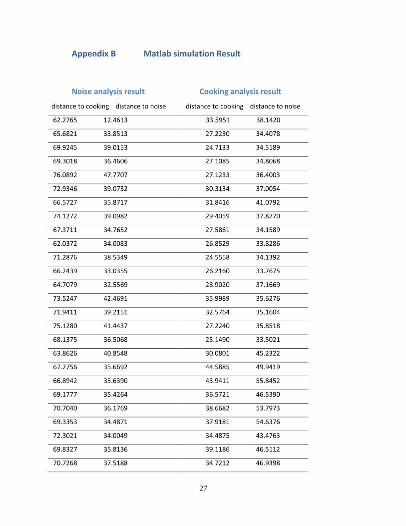
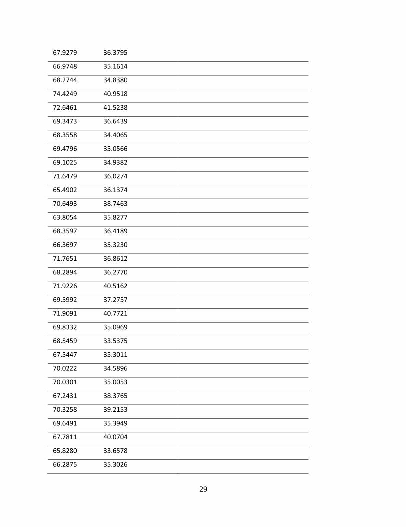
The detailed Matlab simulation result for both noise and keyword is included in the
appendix.

14
3. Design Verification
The complete requirement and verification table is attached in Appendix A.
3.1 Low Pass Filter
Figure 13 Actual frequency response plotted against the theoretical response of the 6th order LPF. Data are taken in
50 Hz increments.
As shown in figure above, although our filter has a higher noise floor, it still follows the
trend of the theoretical frequency response of a six order filter.
3.2 Power
The power unit needs to provide 3.3 V at 10 mA, 5 V as specified in the requirements.
The 2.5 V reference ground is not meant to source current

15
3.3 Power Budget
Table 1 Power Budget Arduino
Active
Arduino
Idle
Arduino
Shutdown
Mic & LPF
5 V
Mic & LPF
1.2 V
Power
(mA/hour)
25 10 10 12 10
Power
*no waste
(mA/hour)
25 4 [1] 0.015 [1] 12 2
The total power consumption of our design now is 37 mA/hour in Active mode. In idle
mode 20 mA/hour in idle mode. However, this is mostly due to waste happened in the power
module design. If we assume no waste happens, we can reduce that to 6mA/hour, or even 2
mA/hour if we can wake up Arduino from shutdown quickly and reliably.
Meanwhile, we may also improve the design by plugging our circuit into power outlet so
that we won’t have to worry too much about power.
3.4 FFT
We are running an 8 bit 256 point FFT with 8000 Hz sample rate. That is, we are able to
inspect 0 to 4000 Hz with 128 bins, and each bin represents 31.25 Hz in frequency. For testing,
we feed a fixed frequency output from the function generator into the microcontroller, and run
the FFT algorithm. Bins with their signal strength higher than a preset threshold will be
considered present, and the highest of all will be our detected signal bin.
As the table below shows, the FFT is accurate within one or two bins, and it satisfies our
requirement.
Table 2 FFT Verification Sample Frequencies
Input
Frequency
300 500 700 1000 3000
Detected
Bins
9 16, 17 22, 23, 24 31, 32, 33 96, 97

16
Corresponding
Frequency
281 531 718 1000
3031

17
4. Costs
4.1 Parts
Table 3 Parts Costs
Part Manufacturer Retail Cost
($)
Bulk
Purchase
Cost ($)
Actual Cost ($)
Smoke Detector Heiman 9.99 N/A 9.99
Arudino Arduino 45.00 N/A 45.00
LM346N Texas Instruments 1.75 N/A 1.75
LM350T05H Texas Instruments 1.63 N/A 3.26
54C6 Microphone Challenge Electronics 0.95 N/A 0.95
2N3904 STMicroelectronics 2.89 N/A 2.89
9V Battery Energizer 8.42 N/A 33.68
Resistor 2.0 kohm RadioShack 1.00 N/A 3.00
Resistor 4.5 kohm RadioShack 1.00 N/A 2.00
Resistor 1.0 Mohm RadioShack 1.00 N/A 4.00
Resistor 4.7 kohm RadioShack 1.00 N/A 1.00
Resistor 2.4 kohm RadioShack 1.00 N/A 1.00
Resistor 11 kohm RadioShack 1.00 N/A 1.00
Resistor 5.6 kohm RadioShack 1.00 N/A 1.00
Resistor 10 kohm RadioShack 1.00 N/A 1.00
Resistor 1.0 kohm RadioShack 1.00 N/A 1.00
Resistor 5.1 kohm RadioShack 1.00 N/A 1.00
Resistor 11 kohm RadioShack 1.00 N/A 1.00
Resistor 1.1 kohm RadioShack 1.00 N/A 1.00
Resistor 120 ohm RadioShack 1.00 N/A 2.00
Resistor 200 ohm RadioShack 1.00 N/A 1.00
Resistor 360 ohm RadioShack 1.00 N/A 1.00
18
Capacitor 1 uF RadioShack 1.00 N/A 1.00
Capacitor 0.1 uF RadioShack 1.00 N/A 2.00
Capacitor 0.15 uF RadioShack 1.00 N/A 1.00
Capacitor 0.22 uF RadioShack 1.00 N/A 1.00
Capacitor 4700 pF RadioShack 1.00 N/A 1.00
Capacitor 3300 pF RadioShack 1.00 N/A 1.00
Capacitor 2200 pF RadioShack 1.00 N/A 1.00
Total 127.52
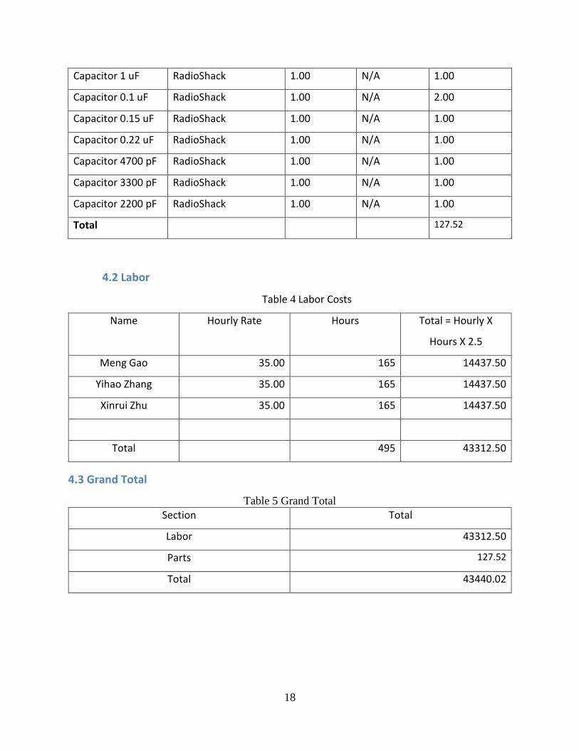
4.2 Labor
Table 4 Labor Costs
Name Hourly Rate Hours Total = Hourly X
Hours X 2.5
Meng Gao 35.00 165 14437.50
Yihao Zhang 35.00 165 14437.50
Xinrui Zhu 35.00 165 14437.50
Total 495 43312.50
4.3 Grand Total
Table 5 Grand Total
Section Total
Labor 43312.50
Parts 127.52
Total 43440.02

19
5. Conclusion
5.1 Accomplishments
We have successfully implemented the clap pattern recognition on Arduino using FFT.
After we integrated it with the other components (buzzer, microphone and smoke detector),
the whole thing works very well during test.
Also, the speech recognition on Matlab has really favorable test result when classify
keyword “cooking” and noise (the two class we built yet).
5.2 Uncertainties
Since Arduino Mega cannot support multi-thread, the sound collection and calculations
cannot operate at the same time. So, it’s really possible that it will miss some clap during
calculation which lead to higher miss rate. Another problem is that the mic is really sensitive
such that even if just touch the wire will result in sound-like voltage input to Arduino which
really interfere the detection.
The Matlab Model we implemented only contains two class now. So it can only
distinguish some word that’s very different. When dealing with some similar words like
“working” or “looking” it will not be able to classify correctly.
5.3 Ethical considerations
1 - To accept responsibility in making decisions consistent with the safety, health, and welfare of the public, and to disclose promptly factors that might endanger the public or the environment;
When making design decisions, we always consider the failure cases. Thus, our DSP is aware of the fire alarm output and its uptime, and takes these into account when making decisions. We will not only disclose the danger of turning off fire alarms, but also take into consideration that the alarm can be turned off by user who did not realizing the danger.
3 - To be honest and realistic in stating claims or estimates based on available data; We will be honest about our testing method and accuracy in fire detection and key word recognition.
5 - To improve the understanding of technology; its appropriate application, and potential consequences;
We will continue to evaluate the application and potential consequences of our smoke alarm.
20
7 - To seek, accept, and offer honest criticism of technical work, to acknowledge and correct errors, and to credit properly the contributions of others;
We meet with our assigned TA every week to seek help and suggestions. When using off-the-shelf hardware components or software libraries, we will cite and credit the respective IP or copyright owners. The algorithm that we implement will also be credited to the relevant owner.
9 - To avoid injuring others, their property, reputation, or employment by false or malicious action;
When testing our design with fire, we take caution to not injure others, their property, reputation, or employment.
10 - To assist colleagues and co-workers in their professional development and to support them in following this code of ethics.
Our team members work together and assist each other in our professional development and to support each other in following the ethics.
5.4 Future work
There’s still a lot improvement we can do in the future.
For the hardware, we can switch from battery power to wall power. Making this switch
will greatly lift the power constraint on various aspect of our project, such as the selection of
the microcontroller. The frequency response of the low pass filter can also improve, by using
more accurate resistors and capacitor, and preferably surface mount rather than through hole.
At the same time, although the noise floor from the filter is not posing a problem for us yet, it
would be ideal to have the noise floor below 0 dB so that any noise that goes through the input
is guaranteed to be suppressed and not saturate the output.
For the software, the first thing we need to do is to improve the accuracy of our
algorithm. For now, our classifier only contains two class: cooking and noise due to the
limitation of training data. In order to improve its reliability especially when dealing with similar
words, we have to introduce much more class. Also, we will implement the word recognition on
micro controller so it can fit into the product. We’re considering about using raspberry pi
because of its outstanding processing performance and the support for unix/linux system which
can incredibly simplify our implementation.

21
References
[1] “8-bit Atmel Microcontroller with 16/32/64KB In-System Programmable Flash”, Amtel, San Jose, California. Feb 2014. Available: http://www.atmel.com/Images/Atmel-2549-8-bit-AVR-Microcontroller-ATmega640-1280-1281-2560-2561_datasheet.pdf [2] “Active Low-Pass Filter Design”, Texas Instruments, Dallas, Texas. 2015. Available: www.ti.com/lit/an/sloa049b/sloa049b.pdf. [Accessed 2 March 2016] [3] Adhar Labs, "RETRIGGERABLE 555 TIMING CIRCUIT: AN INTERESTING FIND", 2013. Available: m8051.blogspot.com/2013/02/retriggerable-555-timing-circuit.html. [Accessed 16 February 2016] [4] BRK Electronics, “What Levels of CO Cause an Alarm”. Available: http://www.brkelectronics.com/faqs/oem/what_levels_of_co_cause_an_alarm. [Accessed 2 March 2016] [5] B. Carter, “A Single-Supply Op-Amp Circuit Collection”, Nov. 2000 [6] D. Ellis (2003). Dynamic Time Warp (DTW) in Matlab
http://www.ee.columbia.edu/~dpwe/resources/matlab/dtw/. [7] D. Jaffe and L. Chavasse, “Comparing CO Content of Cigarette Smoke and Auto Exhaust Using Gas Chromatography”, Dec. 1999. Available: faculty.washington.edu/djaffe/ce3.pdf. [Accessed 2 March 2016] [8] Daniel P. W. Ellis(2005).PLP and RASTA and MFCC, and inversion in Matlab
http://www.ee.columbia.edu/~dpwe/resources/matlab/rastamat/. [9] H. Zumbahlen, “F0 and Q in Filters”, Jan. 12 2008 Available: www.analog.com/media/en/training-seminars/tutorials/MT-210.pdf. [Accessed 28 March 2016] [10] “LM150/LM350A/LM350 3-Amp Adjustable Regulators”, Texas Instruments, Dallas, Texas. 2015. Available: www.ti.com/cn/lit/gpn/lm350a. [Accessed 2 March 2016] [11] "LM555 Timer", Texas Instruments, Dallas, Texas. 2015. Available: www.ti.com/lit/ds/symlink/lm555.pdf. [Accessed 16 February 2016] [12] Open Music Labs Arduino FFT Library. Flingco Sound System, Chicago, Illinois. August, 2012. Available: http://wiki.openmusiclabs.com/wiki/ArduinoFFT?action=AttachFile&do=view&target=ArduinoFFT2.zip [13] “Single Supply Op Amp Design Techniques”, Texas Instruments, Dallas, Texas, March 2001. Available: www.ti.com/lit/an/sloa030a/sloa030a.pdf. [Accessed 28 March 2016] [14] “Toxic Gas Sensor (Model: MQ-7) Manual”, Version 1.3., Winsen Electronics, Zhengzhou, Henan, China. 2014. Available: https://cdn.sparkfun.com/datasheets/Sensors/Biometric/MQ-7%20Ver1.3%20-%20Manual.pdf. [Accessed 2 March 2016] [15] United States Conusumer Product Safety Commision, “Carbon Monoxide Questions and Answers”. Available: www.cpsc.gov/en/Safety-Education/Safety-Education-Centers/Carbon-Monoxide-Information-Center/Carbon-Monoxide-Questions-and-Answers-/. [Accessed 2 March 2016]

22
Appendix A Requirement and Verification Table
High Level Requirements and Alternative Plans
Component High Level Requirement
Photoelectric Smoke Detector
HM-608PS
(0pt)
This is a commercial product. We assume that
it is compliant to the regulation and
requirements, and no verification is needed. It
outputs a square wave to the micro controller
when alarm is triggered.
Microphone Module
(10pt)
ThiVs module obtains captured audio, low pass
filter it at 1000 Hz to remove alarm sound, and
amplifies it to a 0 to 5V
Power
(5pt)
This module provides 3.3V and 5V power. 5V
power can be switched off when not needed.
Micro Controller
(10pt)
The micro controller accepts smoke detector
output, and controls the alarm. It can be put in
low power mode and be woken up by external
interrupt.
Matlab Model for keyword recognition
(15pt)
Able to recognize the key word “cooking” on PC
in Matlab and print out result.
Clap Pattern recognition on micro
controller
(10pt)
Recognize a preset clap pattern on micro
controller in Real Time
Table of Requirements and Verification*
Name Requirements Verification
Power
(5pt)
A) Outputs +5±0.5 V at 50±5mA
to the Microphone module
A)

23
when input is above 2.5V, and
output 1.25±0.1V or less when
input is 0 V
(3 pt)
B) Outputs +3.3±0.3 V at
3±0.3mA to the microcontroller
(2 pt)
1. Attach 100Ω resistor across 3.3 V
source
2. Attach multi-meter across load
3. Supply regulator with 9 V DC
4. Ensure output voltage remains at or
below 1.25±0.1V
5. Supply input with 3.3 V DC
6. Ensure output voltage remains
3.3±0.3V
B)
1. Attach 1000 Ω resistor across 3.3 V
source as load
2. Attach multi-meter across load
3. Supply regulator with 9 V DC
4. Supply power unit input 5 V DC
5. Ensure output voltage remains
3.3±0.3V
Microphone
Low Pass Filter
(10pt)
A) Cutoff Frequency at
1000±100Hz
(2 pt)
B) Pass band gain (200 to 800
Hz) should be 200±20
(4 pt)
C) Stop ban gain (2500 Hz and
above) should have gain at
most 30±5
(4 pt)
1. Attach oscilloscope probes at pin 16
of the op amp and ground
2. Attach function generator probes at
input of the low pass filter
3. Swipe the function generator across
300 to 4000 Hz using sine wave with
amplitude 7 mV.
4. Ensure the oscilloscope shows the
input frequency with 2.5±0.5V
amplitude between 100 to 800 Hz
4. Ensure that the voltage magnitude
rapidly decreases after 1000±100 Hz

24
5. Ensure that the oscilloscope shows
amplitude below 0.3±0.05V for
frequencies greater than 2500 Hz
Micro Controller
(10pt)
A) Receives analog input
(3 pt)
B) Outputs 3000±100 Hz digital
output
(2 pt)
C) FFT detects input wave
frequency, accurate up to ±50
Hz
(5 pt)
A)
1. Attach function generator to pin 2
2. Output 1 Hz sine wave from
function generator
3. Visually inspect that on board LED
flashes at 1 Hz with varying brightness
B)
1. Attach oscilloscope to micro
controller pin 14 as labeled in figure 9.
2. Power on micro controller
3. Ensure oscilloscope oscillates
3000±30 Hz
C)
1. Connect a wave with fixed
frequency generated from a function
generator to the input of
microcontroller, and run the fft
algorithm.
2. Compare the fft output with the
input, and ensure that the difference is
within ±50 Hz.
Matlab Model
(15pt)
A) Correct output when saying
the keyword “cooking”, false
negative rate below 40±10%
(10 pt)
A)
1. Connect microphone to the
computer
2. Run the program

25
B) Correct output when saying
the non-keyword, false positive
rate below 10±10%
(5 pt)
3. Use several sound clips that contain
cooking and check if our program can
detect cooking.
4. Repeat step 2 and 3, ensure the
success ratio reach above 60±10%
B)
1. Connect microphone to the
computer
2. Run the program
3. Use several sound clips that do not
contain cooking and check if our
program can detect cooking.
4. Repeat step 2 and 3, ensure the
success ratio reach above 90±10%
Clap Pattern
Recognition
On micro
controller
(10pt)
A) Correctly stop alarm when
clap three times(accuracy reach
60±10%)
(5 pt)
B) Correctly keep alarm when
did nothing (accuracy reach
90±10%)
(4 pt)
C) Correctly retriggers alarm
when the alarm is on for more
than 10 min(accuracy reach
100±10%)
A)
1. Turn on the program on micro
controller manually
2. Connect oscilloscope to the alarm
signal output and ground
2. Send an ON signal to micro
controller.
3. Ensure that alarm signal output at 3
kHz±100 Hz
4. Clap three times quickly, and check
alarm signal output is 0±0.5 V.
5. Repeat step 2 and 3 ten times, and
ensure that six or more trials succeed.
B)

26
(1 pt) 1. Turn on the program on micro
controller manually
2. Connect oscilloscope to the alarm
signal output and ground
2. Send an ON signal to micro
controller.
3. Ensure that alarm signal output at 3
kHz±100 Hz
4. Clap only one time, and check alarm
signal output oscillates at 3 kHz ±100
Hz.
5. Repeat step 3 and 4 with two claps,
four claps, and with short pauses of
"ah" sound, ensure that neither
triggers the alarm.
c)
1. Turn on the program on micro
controller manually
2. Send ON signal to micro controller
3. Manually suppress alarm
4. Wait for 10 minutes
5. Ensures that the alarm signal output
re-triggeres and output 3 kHz ±100 Hz.
27
Appendix B Matlab simulation Result
Noise analysis result Cooking analysis result
distance to cooking distance to noise distance to cooking distance to noise
62.2765 12.4613 33.5951 38.1420
65.6821 33.8513 27.2230 34.4078
69.9245 39.0153 24.7133 34.5189
69.3018 36.4606 27.1085 34.8068
76.0892 47.7707 27.1233 36.4003
72.9346 39.0732 30.3134 37.0054
66.5727 35.8717 31.8416 41.0792
74.1272 39.0982 29.4059 37.8770
67.3711 34.7652 27.5861 34.1589
62.0372 34.0083 26.8529 33.8286
71.2876 38.5349 24.5558 34.1392
66.2439 33.0355 26.2160 33.7675
64.7079 32.5569 28.9020 37.1669
73.5247 42.4691 35.9989 35.6276
71.9411 39.2151 32.5764 35.1604
75.1280 41.4437 27.2240 35.8518
68.1375 36.5068 25.1490 33.5021
63.8626 40.8548 30.0801 45.2322
67.2756 35.6692 44.5885 49.9419
66.8942 35.6390 43.9411 55.8452
69.1777 35.4264 36.5721 46.5390
70.7040 36.1769 38.6682 53.7973
69.3353 34.4871 37.9181 54.6376
72.3021 34.0049 34.4875 43.4763
69.8327 35.8136 39.1186 46.5112
70.7268 37.5188 34.7212 46.9398

28
70.4195 39.4216 36.1372 43.3358
70.6602 36.2662 29.9987 45.5489
71.8340 38.3474 43.5669 50.6924
64.0021 40.2228 35.9382 49.4233
67.2055 33.9057 48.0329 57.2894
70.3913 35.8990 39.7986 50.0708
68.3618 35.3293 49.6112 56.8040
69.4612 35.4278 48.1529 56.4695
68.3082 36.0433 30.0367 46.1466
69.0775 35.5428 31.5742 51.3680
67.8478 32.8666 33.7385 49.1941
64.8660 33.8682 29.2069 46.5640
69.1725 35.2138 33.5868 44.5973
66.5098 33.8328 32.3587 45.7616
71.0968 37.8636 25.1613 43.6797
68.4755 35.3426 31.0744 49.9172
72.9414 39.7645 25.7492 40.7840
66.6822 35.5366 32.1601 44.4050
66.8865 33.7873 37.3760 45.1842
68.6309 34.4589 35.5443 44.3869
66.3836 32.6135 34.4933 42.6806
66.3712 33.3205 22.7320 42.0030
64.6673 34.4898 31.2020 44.8822
68.5889 34.4502 31.3712 49.4993
66.4805 33.9463 32.1810 47.7848
68.7272 35.5198
67.4316 34.8088
70.9031 37.9681
68.2332 37.9541
68.9742 37.0508
69.4486 40.6347
29
67.9279 36.3795
66.9748 35.1614
68.2744 34.8380
74.4249 40.9518
72.6461 41.5238
69.3473 36.6439
68.3558 34.4065
69.4796 35.0566
69.1025 34.9382
71.6479 36.0274
65.4902 36.1374
70.6493 38.7463
63.8054 35.8277
68.3597 36.4189
66.3697 35.3230
71.7651 36.8612
68.2894 36.2770
71.9226 40.5162
69.5992 37.2757
71.9091 40.7721
69.8332 35.0969
68.5459 33.5375
67.5447 35.3011
70.0222 34.5896
70.0301 35.0053
67.2431 38.3765
70.3258 39.2153
69.6491 35.3949
67.7811 40.0704
65.8280 33.6578
66.2875 35.3026

30
65.8951 34.5885
72.9533 38.6884
68.7052 34.5906
69.8043 34.4322
69.7659 38.5258
65.8127 36.0320
69.2653 36.6120
66.9459 36.1898
64.6727 39.8269
71.0717 34.1367
66.8759 34.5595
Success Rate: 99/100 Success Rate: 50/52