Embed Size (px)
Citation preview
0
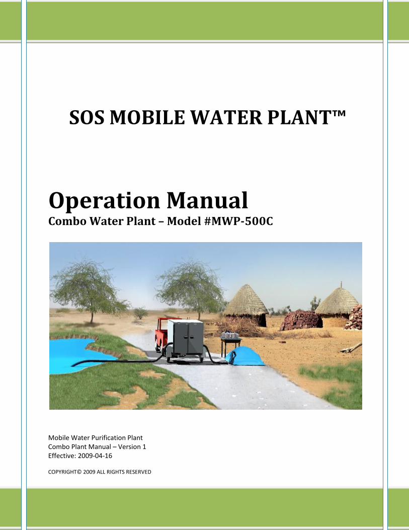
SOS MOBILE WATER PLANT™
Operation Manual Combo Water Plant – Model #MWP-500C
Mobile Water Purification Plant Combo Plant Manual – Version 1 Effective: 2009-04-16
COPYRIGHT© 2009 ALL RIGHTS RESERVED
1 Mobile Water Purification Plant Combo Plant Manual – Version 1 Effective: 16-Apr-09
1 Table of Contents 2 INTRODUCTION ..................................................................................................................................................... 2
2.1 General Information ..................................................................................................................................... 2
2.2 The Manual .................................................................................................................................................. 2
2.3 System Function ........................................................................................................................................... 2
2.4 System Components Functions .................................................................................................................... 2
2.5 IMPORTANT SAFETY WARNINGS.................................................................................................................. 3
3 SPECIFICATIONS .................................................................................................................................................... 4
3.1 General System Specifications ..................................................................................................................... 4
4 INSTALLATION & SET-UP INSTRUCTIONS .............................................................................................................. 5
4.1 Components Identification .......................................................................................................................... 5
4.2 Precaution before Installation ..................................................................................................................... 5
4.3 System Location ........................................................................................................................................... 5
4.4 Plumbing Connections ................................................................................................................................. 5
4.5 Initial Set-Up of System for operation ......................................................................................................... 6
5 OPERATING INSTRUCTIONS .................................................................................................................................. 8
5.1 REVERSE OSMOSIS (RO) SYSTEM OPERATING INSTRUCTIONS: ................................................................... 9
6 MAINTENANCE .................................................................................................................................................... 11
6.1 Pre-Filter #1 Cartridge Replacement .......................................................................................................... 11
6.2 D.E. Filter Maintenance .............................................................................................................................. 11
6.3 Purification Media & Carbon Filters ........................................................................................................... 11
6.4 Final Filter Maintenance ............................................................................................................................ 11
6.5 UV Light sterilizer Maintenance ................................................................................................................. 12
6.6 General Maintenance................................................................................................................................. 12
7 SPARE PARTS & CONSUMABLE ITEMS ................................................................................................................ 12
8 P&ID SYSTEM DRAWING ..................................................................................................................................... 13
9 APPENDIX ............................................................................................................................................................ 14
9.1 Appendix 1: 7500 Watt Electrical Generator, Model #APG3075 ............................................................... 15
9.2 Appendix 2: IRRI-GATOR Forwarding Pump, Model #GT07 ....................................................................... 16
9.3 Appendix 3: Diatomaceous Earth (D.E.) Filter (Model #EC40) ................................................................... 21
9.4 Appendix 4: Sanitron UV Water Sterilizer, Model #S50C ........................................................................... 27
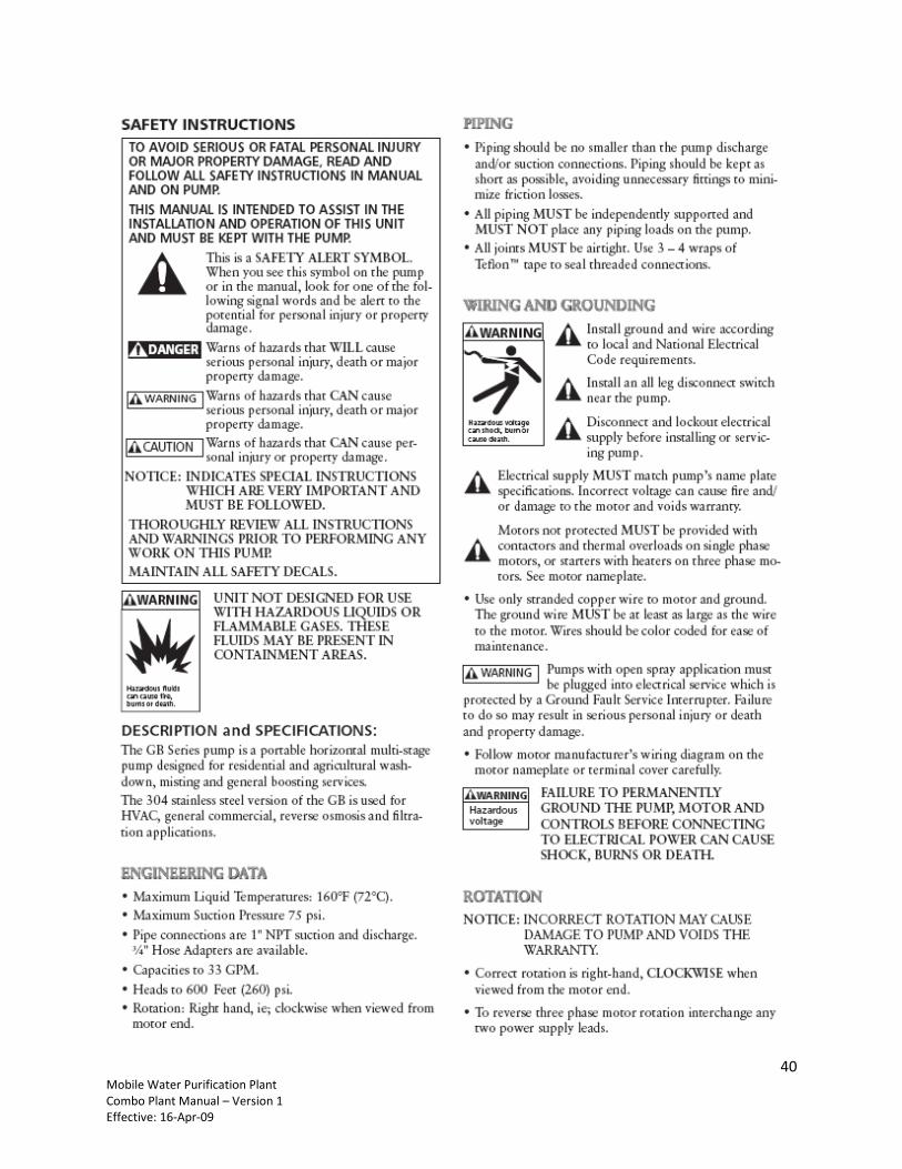
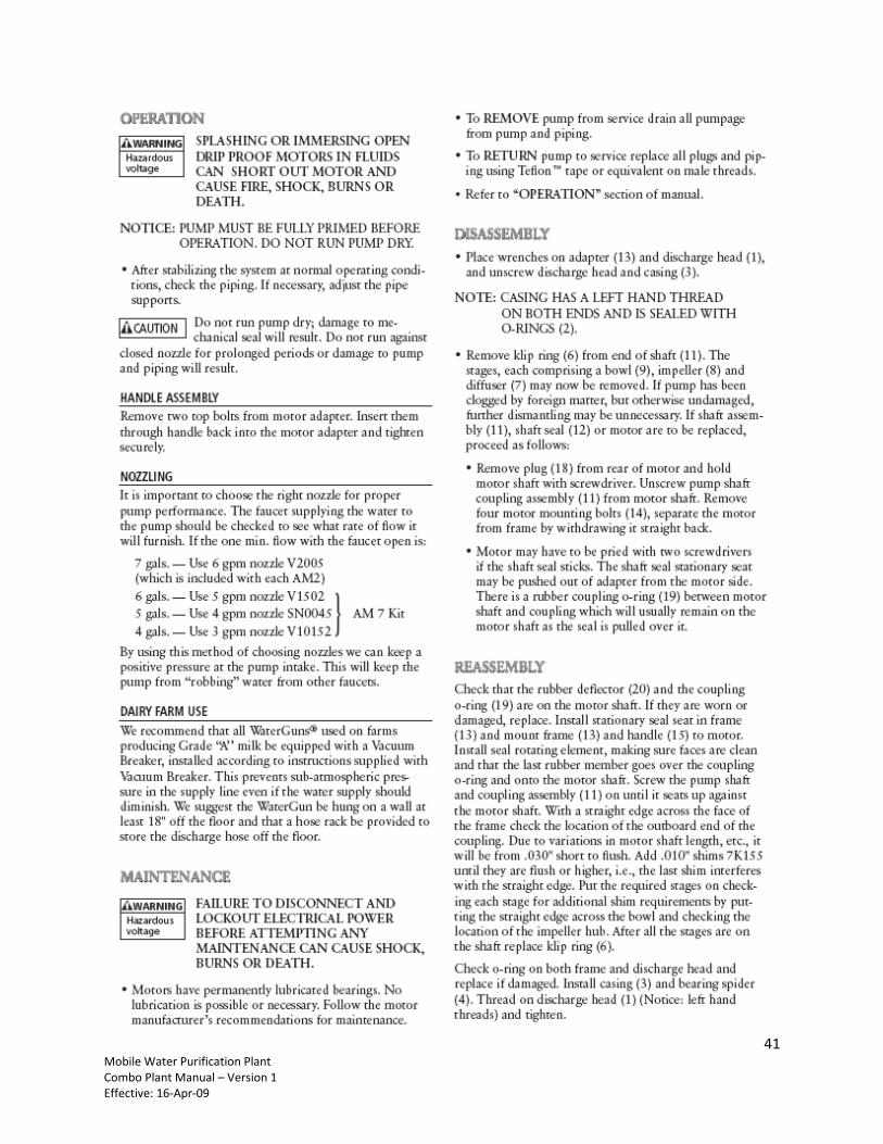
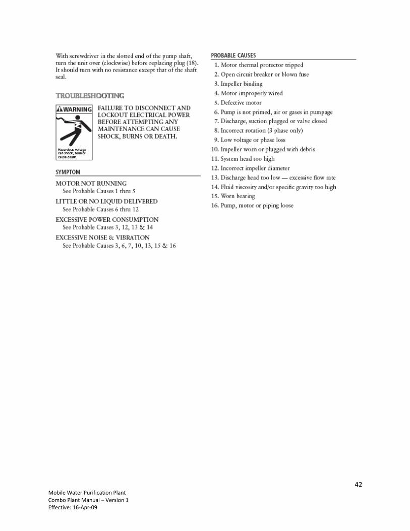
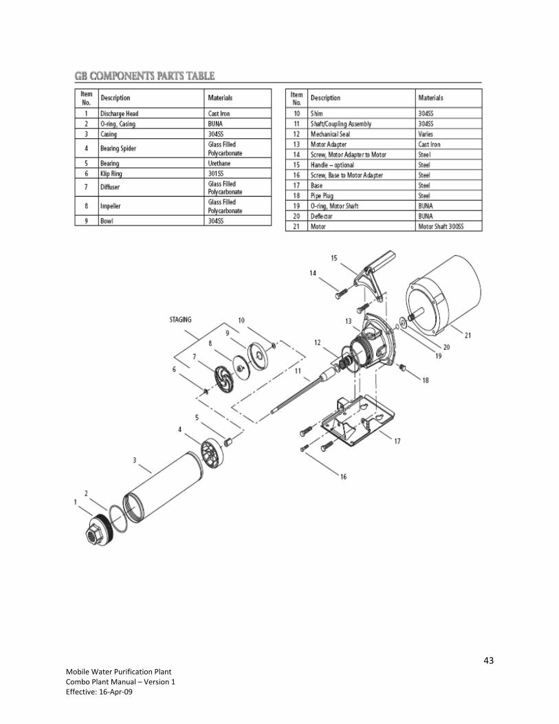
9.5 Appendix 5: RO Pump Manual Model #18GBC30 ...................................................................................... 38
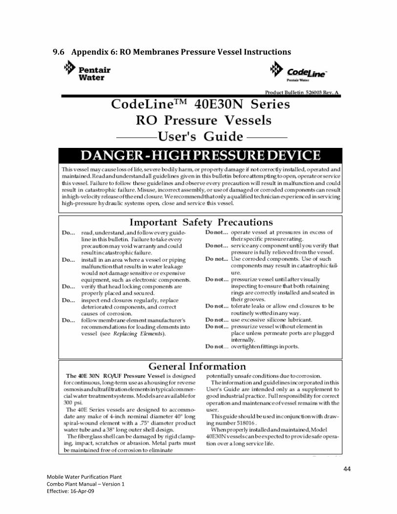
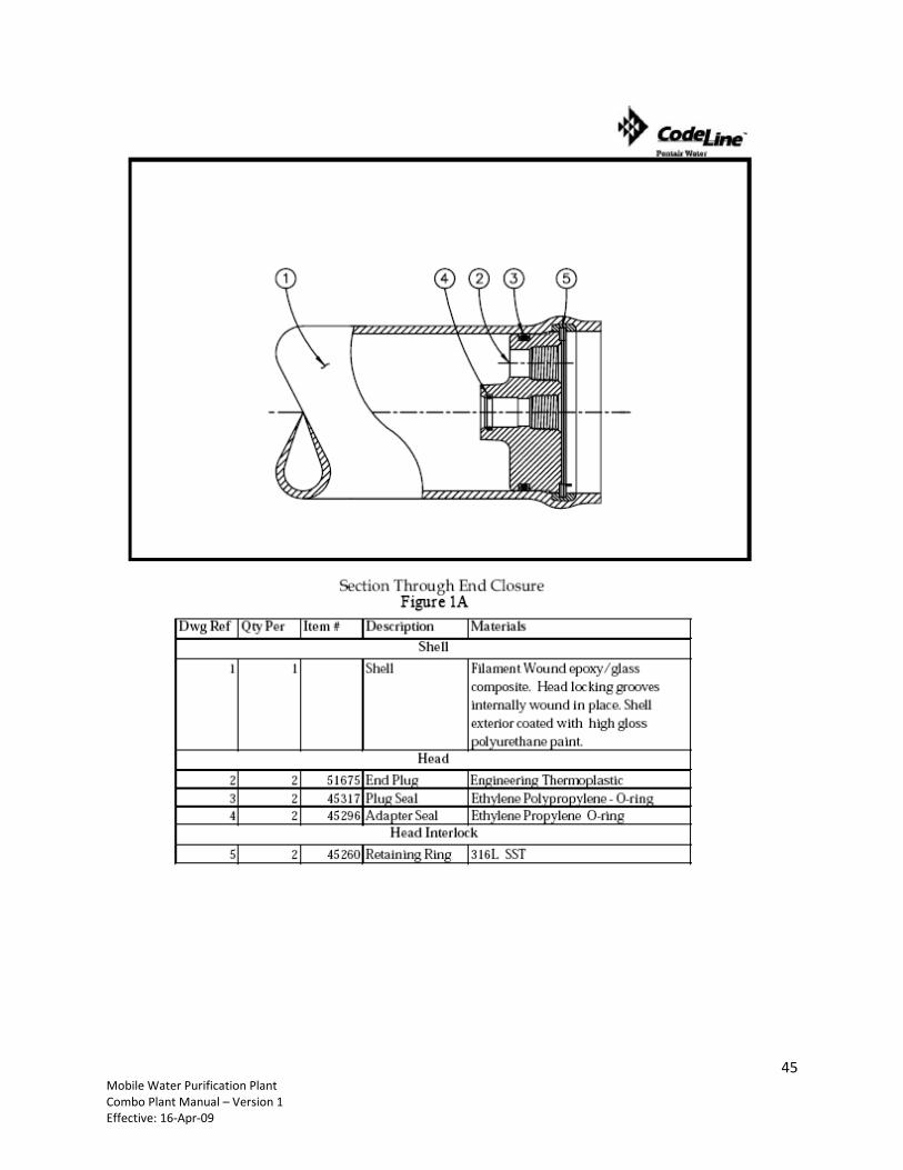
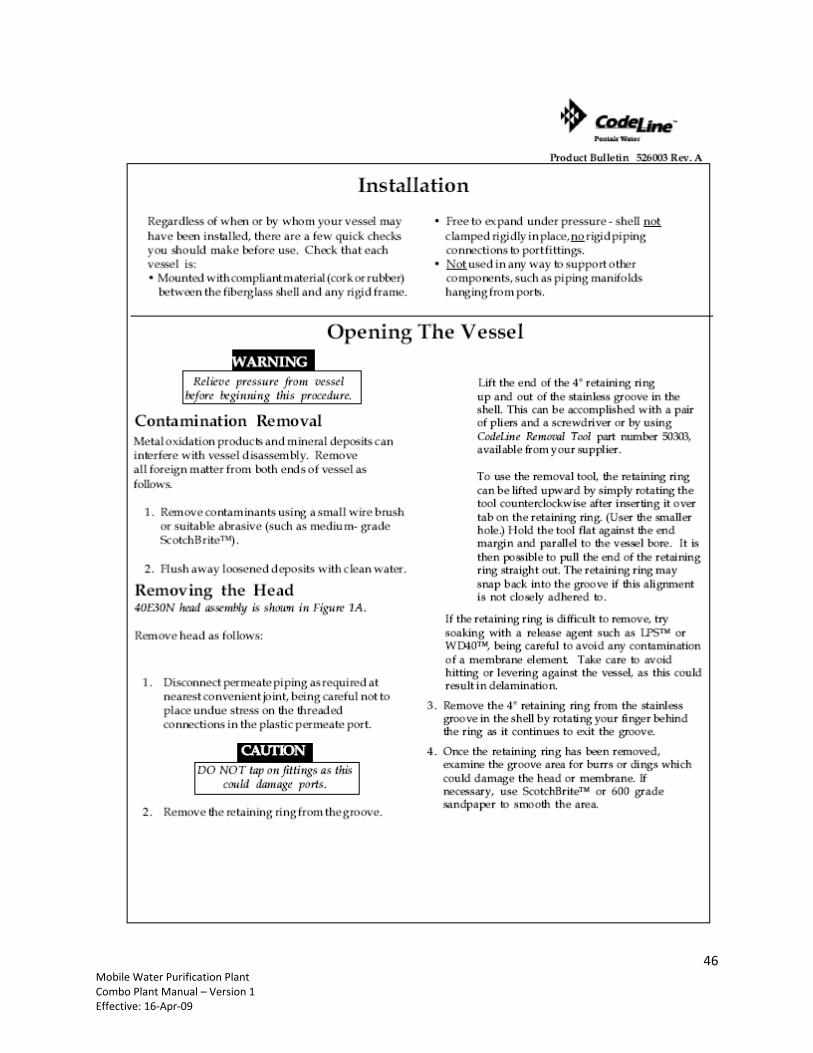
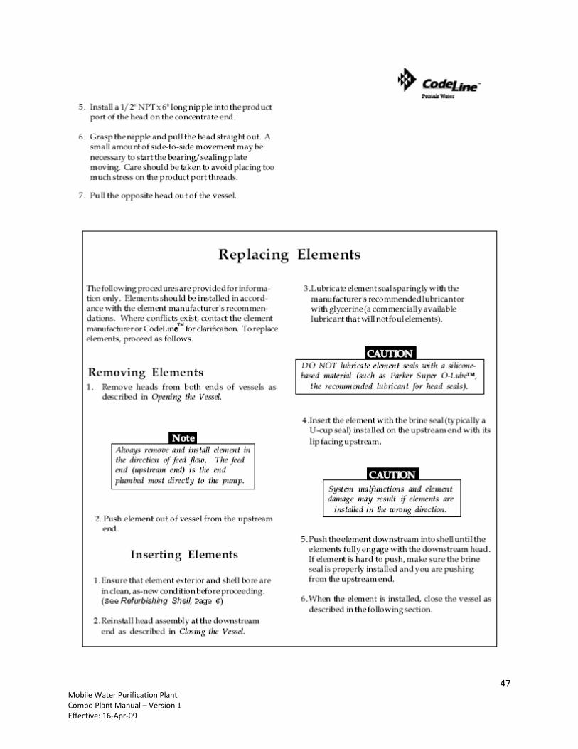
9.6 Appendix 6: RO Membranes Pressure Vessel Instructions ........................................................................ 44
9.7 Appendix 7: Collapsible Portable Drinking water storage Tanks ............................................................... 51
2 Mobile Water Purification Plant Combo Plant Manual – Version 1 Effective: 16-Apr-09
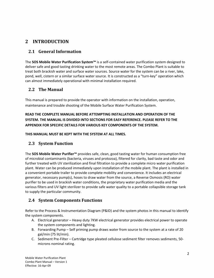
2 INTRODUCTION
2.1 General Information The SOS Mobile Water Purification System™ is a self-contained water purification system designed to deliver safe and good tasting drinking water to the most remote areas. The Combo Plant is suitable to treat both brackish water and surface water sources. Source water for the system can be a river, lake, pond, well, cistern or a similar surface water source. It is constructed as a “turn-key” operation which can almost immediately operational with minimal installation required.
2.2 The Manual This manual is prepared to provide the operator with information on the installation, operation,
maintenance and trouble shooting of the Mobile Surface Water Purification System.
READ THE COMPLETE MANUAL BEFORE ATTEMPTING INSTALLATION AND OPERATION OF THE
SYSTEM. THE MANUAL IS DIVIDED INTO SECTIONS FOR EASY REFERENCE. PLEASE REFER TO THE
APPENDIX FOR SPECIFIC DETAILS FOR VARIOUS KEY COMPONENTS OF THE SYSTEM.
THIS MANUAL MUST BE KEPT WITH THE SYSTEM AT ALL TIMES.
2.3 System Function The SOS Mobile Water Purifier™ provides safe, clean, good tasting water for human consumption free of microbial contaminants (bacteria, viruses and protozoa), filtered for clarity, bad taste and odor and further treated with UV sterilization and final filtration to provide a complete micro water purification plant. Water can be produced immediately upon installation of the mobile plant. The plant is installed in a convenient portable trailer to provide complete mobility and convenience. It includes an electrical generator, necessary pump(s), hoses to draw water from the source, a Reverse Osmosis (RO) water purifier to be used in brackish water conditions, the proprietary water purification media and the various filters and UV light sterilizer to provide safe water quality to a portable collapsible storage tank to supply the particular community.
2.4 System Components Functions Refer to the Process & Instrumentation Diagram (P&ID) and the system photos in this manual to identify the system components.
A. Electrical generator – Heavy duty 7KW electrical generator provides electrical power to operate the system components and lighting.
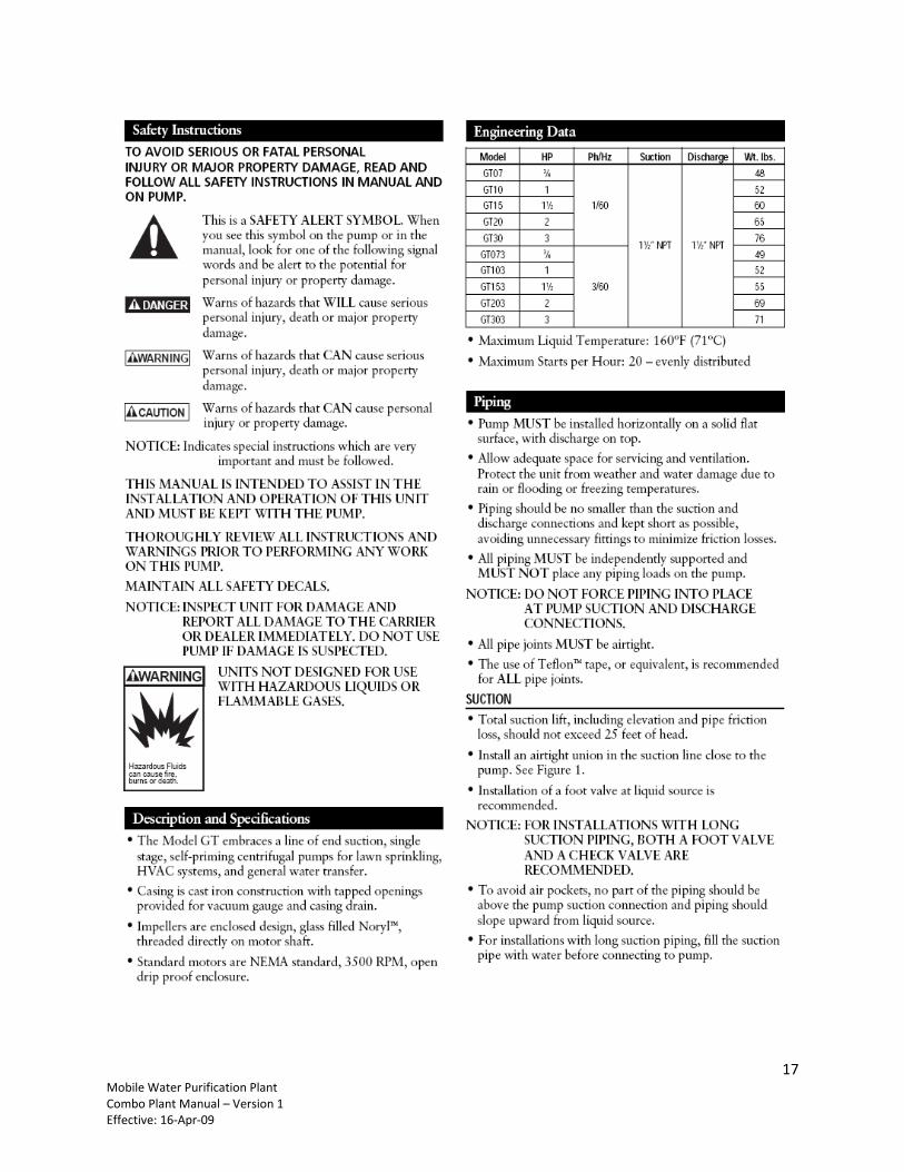
B. Forwarding Pump – Self priming pump draws water from source to the system at a rate of 20 gal/min (75 lit/min).
C. Sediment Pre-Filter – Cartridge type pleated cellulose sediment filter removes sediments, 50-microns nominal rating.
3 Mobile Water Purification Plant Combo Plant Manual – Version 1 Effective: 16-Apr-09
D. DE Filter – Diatomaceous Earth is a high performance filter most efficient for dirt and sediment removal.
E. Reverse Osmosis (RO) – Brackish water RO plant for the removal of excessive dissolved solids and other impurities if feed water is high on TDS (greater than 500 mg/l). The RO plan treats at a flow rate of 5-6 GPM (18-22 lpm).
F. Purification Media – This proprietary water purification media kills bacteria and virus immediately upon contact. There are five (5) purification canisters in a parallel connection to accommodate the design flow rate up to 20 GPM (75 lpm). When system is used with the brackish water RO option only the two (2) media canisters are used.
G. Carbon Filters – Removes organic contaminants and bad taste and odors from the water. H. UV Sterilizer – Final protection against microbial contamination. I. Final Filter – High capacity activate carbon filter, 5-micron provides final polishing. J. Water Meter – Totalizes purified water production to monitor purification capacity and system
maintenance. K. Accessories – Various accessories are included like two hose reels each with 50 ft (15 m) of food
grade braided high pressure flexible hose, one for the inlet one for the outlet. A tool box contains miscellaneous tools and test kits required for the operation of the system.
L. Storage Tank – A collapsible flexible portable storage tank is included to store product water for proper distribution. Various sizes are available
2.5 IMPORTANT SAFETY WARNINGS
WARNING: To guard against injury, basic safety precautions should be observed, including:
1. DO NOT USE the water purifier with sea water source or water with salinity of greater than 1,000mg/l. The system does not reduce Total Dissolved Solids or is not intended to be used for desalination of water.
2. WARNING: Intended use of the system is to provide potable water from a questionable surface water source by removing pathogens, low molecular weight organics and bad taste and odor, thus making the water suitable for human consumption for emergency and humanitarian applications.
3. WARNING: DO NOT USE WITH HEAVILY POLLUTED, BRACKISH OR SALT WATER.
4. PRECAUTIONARY STATEMENT HUMAN EFFECTS:
The possibility exists that small amount of Iodine may be present in the treated water. Persons with thyroid problems, pregnant women and children should consult a doctor before extended use of the water produced by this system.
5. WARNING: Do not operate the system while the electrical generator is turned on with the doors closed. Keep the doors open to allow proper ventilation in the trailer. Refer to the instruction section for the electrical generation for proper safety warnings and instructions.
6. DANGER: Carbon Monoxide – Operating the electrical generator without proper ventilation will create dangerous levels of carbon monoxide that can result in severe injury or death.
4 Mobile Water Purification Plant Combo Plant Manual – Version 1 Effective: 16-Apr-09
7. WARNING! IMPROPER OPERATION OR MAINTENANCE OF THIS PRODUCT COULD RESULT IN SERIOUS INJURY. MAKE SURE YOU ARE USING THIS PRODUCT ACCORDING TO THE INSTRUCTIONS SPECIFIED IN THIS MANUAL.
3 SPECIFICATIONS
3.1 General System Specifications The following general specifications are provided as the average system performance. Refer to the Notes below for more details.
Model No. MWP-500S MWP-500C
Water Source Surface Water Surface & Brackish Trailer size 5’x8’ (1.5m x 2.5m) 6’x12’ (1.8m x 3.7m) Power Requirements 7500 Watt gasoline electrical generator, 13-Hp, 120/240V & 12V outlets Forwarding Pump Self Priming Centrifugal Pump, ¾ HP, 3500 RPM,
20 GPM @ 40 psi boost, 25’ max. vertical lift @ 20 GPM Pre-Filter - #1 Pre-Filter - #2
30 µm pleated cellulose sediment filter cartridge Diatomaceous Earth (DE) backwashable filter
RO system NO YES (6 GPM max flow) Purification Media* 2.5 Ft³ (5x0.5 Ft3) 2.5 Ft³ (5x0.5 Ft3) Carbon Filtration* 7.5 Ft3 (5x1.5 Ft3) 7.5 Ft3 (5x1.5 Ft3) UV sterilizer S-50C UV sterilizer, SS construction controls microbiological purity Final Filter Large cartridge type, 5 µm pulverized activated carbon Flow Rate 20 GPM (75 lpm) 20 GPM (75 lpm) for surface water
5-6 GPM (19-22 lpm) for brackish water RO Treatment Capacity 500,000 Gal (1,890 M3) total purification media capacity** Media Tanks Non-corrosive FRP wound pressure vessels, 150 psi max work pressure Storage Tank Flexible Collapsible tank, FDA grade material. 130 gal min capacity
NOTES:
Purification media and carbon filtration is distributed in a parallel 5x1 flow array
The capacity of the system is rated by the estimated capacity of the Purification Media. The Purification media must be replaced before its rated “kill” capacity is exhausted. Media kills bacteria and virus on demand only if such pathogens are present, rendering water safe to drink.
Activated carbon media is used to remove turbidity, organic chemicals and taste and odor.
Min. storage tank with the system is 130 gal (500 lit). Other storage tank sizes are available, specify when ordering.
The filter replacement and DE backwash is dependent directly on the feed water quality and source. Filters may need to be replaced accordingly as specified further in this manual.
5 Mobile Water Purification Plant Combo Plant Manual – Version 1 Effective: 16-Apr-09
4 INSTALLATION & SET-UP INSTRUCTIONS The system is factory pre assembled and pre-plumbed ready to be used. Limited installation is required. See Figure 1 and Table 1 below to identify all the components of the system
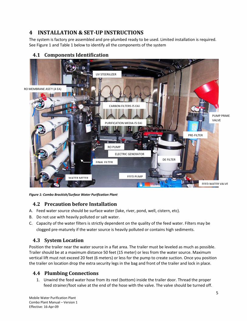
4.1 Components Identification
Figure 1: Combo Brackish/Surface Water Purification Plant
4.2 Precaution before Installation A. Feed water source should be surface water (lake, river, pond, well, cistern, etc).
B. Do not use with heavily polluted or salt water.
C. Capacity of the water filters is strictly dependent on the quality of the feed water. Filters may be
clogged pre-maturely if the water source is heavily polluted or contains high sediments.
4.3 System Location Position the trailer near the water source in a flat area. The trailer must be leveled as much as possible. Trailer should be at a maximum distance 50 feet (15 meter) or less from the water source. Maximum vertical lift must not exceed 20 feet (6 meters) or less for the pump to create suction. Once you position the trailer on location drop the extra security legs in the bag and front of the trailer and lock in place.
4.4 Plumbing Connections 1. Unwind the feed water hose from its reel (bottom) inside the trailer door. Thread the proper
feed strainer/foot valve at the end of the hose with the valve. The valve should be turned off.
FEED WATER VALVE
PUMP PRIME
VALVE
FEED PUMP
FINAL FILTER
WATER METER
PRE-FILTER
PURIFICATION MEDIA (5 EA)
CARBON FILTERS (5 EA)
ELECTRIC GENERATOR
DE FILTER
UV STEERILIZER
RO MEMBRANE ASS’Y (4 EA)
RO PUMP
6 Mobile Water Purification Plant Combo Plant Manual – Version 1 Effective: 16-Apr-09
Connect the quick connect fitting on the other end of the hose to the INLET water quick connect fitting. The INLET is located at the right back side of the trailer and marked INLET.
2. Unwind the outlet hose from the top reel. Connect the one quick connect fitting to the OUTLET quick connect fitting of the trailer located on the left back side of the trailer and marked OUTLET.
3. If the system is being used with a flexible collapsible storage tank provided, lay a protective
plastic liner on a flat surface and then open up on it the storage tank flat. Connect the output
hose to the storage tank fill fitting.
4.5 Initial Set-Up of System for operation Follow the following steps to make sure that the system is set-up properly before setting it in operation.
1. Check and start-up the electrical generator. Refer to the generator manual in Appendix 1 for the complete electrical generator manual. Read and understand the manual thoroughly before operating the generator.
Starting the generator: Check that the engine power switch is in its “OFF” position. Make sure that the proper cables are connected to the electric battery poles and that the
battery is fully charged. If battery is not charged you will not be able to use the electric start. Make sure the fuel tank is filled with gasoline. Fill with gasoline if necessary.
THE GENERATOR MUST BE TURNED OFF AND COOLED DOWN BEFORE REFILLING TANK Check the engine oil level and make sure that it is in the proper level. Change oil every 20
hours of operation. Make sure the air filter is in place Disconnect all electrical power devices, and turn the AC circuit breakers (switches) OFF. Turn the fuel valve to the “ON” position. Close the choke. Turn the key to the “START” position and allow the engine to crank. When engine starts,
release the key back to the “RUN” position.
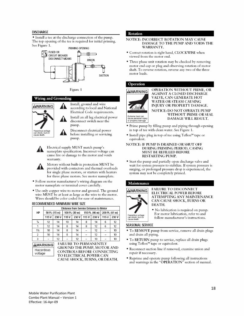
2. Priming the Pump The forwarding pump needs to be primed first at start up. Refer to Appendix 2 to view the complete pump manual. To initially prime the pump follow the steps below: Insert the suction end of the hose with the foot valve/strainer in the source water.
Make sure that it is submersed in the water body permanently and there is no chance for it coming out of the water body. This avoids the suction of air during normal operation.
To avoid air pockets, no part of the piping should be above the pump suction connection and the hose should slope upward from the water body. Make sure that there is a straight run as much as possible and that there are any unnecessary loops and no kinks and obstructions.
It is advisable especially with long suction tubing, to fill the suction tubing before connecting to the inlet fitting. Use the funnel provided for convenience.
7 Mobile Water Purification Plant Combo Plant Manual – Version 1 Effective: 16-Apr-09
Open the prime valve and install the funnel on the priming fitting. Fill the pump with water until water overflows, turn the prime valve off.
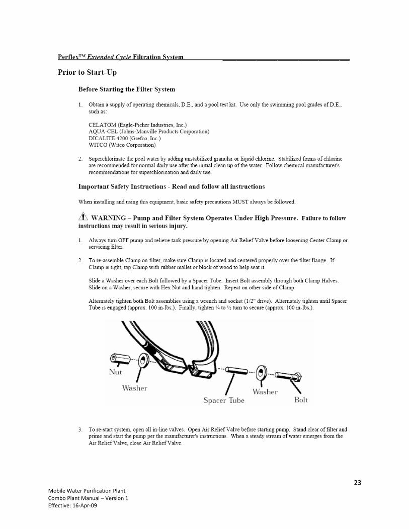
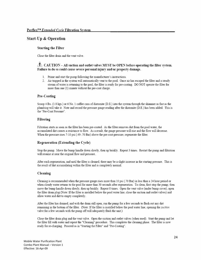
3. Precoating the Diatomaceous Earth Filter (Pre-Filter #2) The filter needs to be coated with a uniform coat of 1/16” – 1/8” thick diatomaceous earth (D.E.) also called “diatomite”. Follow the following steps: Remove the 20” filter housing sump from Pre-Filter 1 and remove the filter cartridge. Add diatomaceous earth (DE) about 4 lbs (1.8 kgr) or about 1/3 of the housing sump. Add water to the sump and mix well to make thin slurry. You may use a separate bucket to
make the slurry and transfer the slurry to the housing sump if this is more convenient. Place the sump with the slurry back on the housing head (make sure the O-ring seal is in
place) Set the filter control valve or effluent valve to “recirculate” or “rinse”. Turn the pump on and
transfer the slurry into the DE filter. Note and record the pressure gauge reading after the diatomite has been added. This is the “precoat” pressure.
Stop the pump and “regenerate” the filter by moving the bump handle down slowly, and then up briskly. Repeat 3 – 4 times.
Refer to Appendix 3 to view the complete manual for the D.E filter.
4. Re-install the filter cartridge in the housing of Pre-Filter #1, make sure the O-ring seal is in –place.
Now you are ready to start producing safe, clean water.
8 Mobile Water Purification Plant Combo Plant Manual – Version 1 Effective: 16-Apr-09
5 OPERATING INSTRUCTIONS System is very simple to operate. Follow the following steps itemized for your convenience.
Make sure the feed water hose is full with water and that the pump is primed.
Make sure the pump and the UV sterilizer are plugged in to the generator outlets. You can turn
the power to the units ON or OFF with the switches in the front of the generator.
Turn the UV switch ON and make the UV lamp turns ON. You will observe a blue color light in
the sight port. Refer to Appendix 5 for complete UV manual.
Turn inlet valves ON and turn the pump ON. Water should start flowing through the system.
Crack open the various bleed valves to relief any air entrapment.
Open the OUTPUT valve and wait until water is flowing out freely.
Make sure the product is flowing out clear before you start collecting in containers or connect to
the storage tank.
Record the meter reading before and after every use in the attached Water Meter Log.
Test water for Total Dissolve Solids and pH with meters provided and record in your log sheet.
Keep observing the various pressure gauges. If you will observe excessive pressure drops and
will notice diminishing production flow, you may need to stop the system and bump (backwash)
the DE filter and/or replace the prefilter cartridge. This will vary with the quality of the source
water.
Once the storage tank is filled or you are done with the usage turn the pump and UV breakers
(switches) OFF at the generator.
Turn the generator OFF.
If the system will be used again in the same location in the repeated basis let the system idle.
Turning System Off and preparing to move
If you are complete with this location and you will be moving the trailer to another location you
will need to drain the water from the system and prepare the trailer to be moved.
To drain the system, turn the drain valves for the various components ON. Run the pump on for
a short time to pump all the water out as much as possible. Turn pump OFF if it cavitates. When
there is no flow out of the drain valves, turn them off.
Unplug the pump and UV sterilizer; make sure that the breaker switches are OFF and the
generator in the OFF position.
Drain the hoses and recoil in the corresponding hose reels.
9 Mobile Water Purification Plant Combo Plant Manual – Version 1 Effective: 16-Apr-09
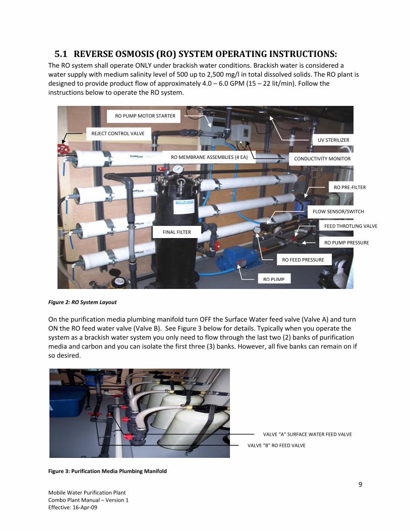
5.1 REVERSE OSMOSIS (RO) SYSTEM OPERATING INSTRUCTIONS: The RO system shall operate ONLY under brackish water conditions. Brackish water is considered a water supply with medium salinity level of 500 up to 2,500 mg/l in total dissolved solids. The RO plant is designed to provide product flow of approximately 4.0 – 6.0 GPM (15 – 22 lit/min). Follow the instructions below to operate the RO system.
Figure 2: RO System Layout
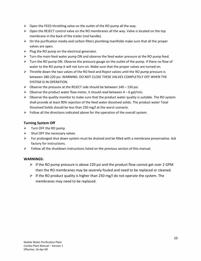
On the purification media plumbing manifold turn OFF the Surface Water feed valve (Valve A) and turn ON the RO feed water valve (Valve B). See Figure 3 below for details. Typically when you operate the system as a brackish water system you only need to flow through the last two (2) banks of purification media and carbon and you can isolate the first three (3) banks. However, all five banks can remain on if so desired.
Figure 3: Purification Media Plumbing Manifold
RO PUMP
RO FEED PRESSURE
RO MEMBRANE ASSEMBLIES (4 EA)
REJECT CONTROL VALVE
FEED THROTLING VALVE
RO PUMP PRESSURE
RO PRE-FILTER
RO PUMP MOTOR STARTER
CONDUCTIVITY MONITOR
FLOW SENSOR/SWITCH
FINAL FILTER
UV STERILIZER
VALVE “B” RO FEED VALVE
VALVE “A” SURFACE WATER FEED VALVE
10 Mobile Water Purification Plant Combo Plant Manual – Version 1 Effective: 16-Apr-09
Open the FEED throttling valve on the outlet of the RO pump all the way.
Open the REJECT control valve on the RO membranes all the way. Valve is located on the top
membrane in the back of the trailer (red handle).
On the purification media and carbon filters plumbing manifolds make sure that all the proper
valves are open.
Plug the RO pump on the electrical generator.
Turn the main feed water pump ON and observe the feed water pressure at the RO pump feed.
Turn the RO pump ON. Observe the pressure gauge on the outlet of the pump. If there no flow of
water to the RO pump it will not turn on. Make sure that the proper valves are turned on.
Throttle down the two valves of the RO feed and Reject valves until the RO pump pressure is
between 180-220 psi. WARNING: DO NOT CLOSE THESE VALVES COMPLETELY OFF WHEN THE
SYSTEM IS IN OPERATION.
Observe the pressure at the REJECT side should be between 140 – 150 psi.
Observe the product water flow meter, it should read between 4 – 6 gal/min.
Observe the quality monitor to make sure that the product water quality is suitable. The RO system
shall provide at least 90% rejection of the feed water dissolved solids. The product water Total
Dissolved Solids should be less than 250 mg/l at the worst scenario.
Follow all the directions indicated above for the operation of the overall system.
Turning System Off
Turn OFF the RO pump.
Shut OFF the necessary valves
For prolonged shut down system must be drained and be filled with a membrane preservative. Ask
factory for instructions.
Follow all the shutdown instructions listed on the previous section of this manual.
WARNINGS:
If the RO pump pressure is above 220 psi and the product flow cannot get over 2 GPM
then the RO membranes may be severely fouled and need to be replaced or cleaned.
If the RO product quality is higher than 250 mg/l do not operate the system. The
membranes may need to be replaced.
11 Mobile Water Purification Plant Combo Plant Manual – Version 1 Effective: 16-Apr-09
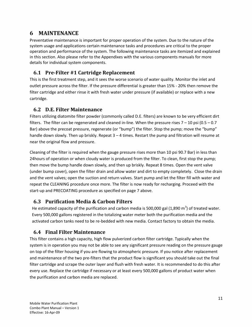
6 MAINTENANCE Preventative maintenance is important for proper operation of the system. Due to the nature of the system usage and applications certain maintenance tasks and procedures are critical to the proper operation and performance of the system. The following maintenance tasks are itemized and explained in this section. Also please refer to the Appendixes with the various components manuals for more details for individual system components.
6.1 Pre-Filter #1 Cartridge Replacement This is the first treatment step, and it sees the worse scenario of water quality. Monitor the inlet and
outlet pressure across the filter. If the pressure differential is greater than 15% - 20% then remove the
filter cartridge and either rinse it with fresh water under pressure (if available) or replace with a new
cartridge.
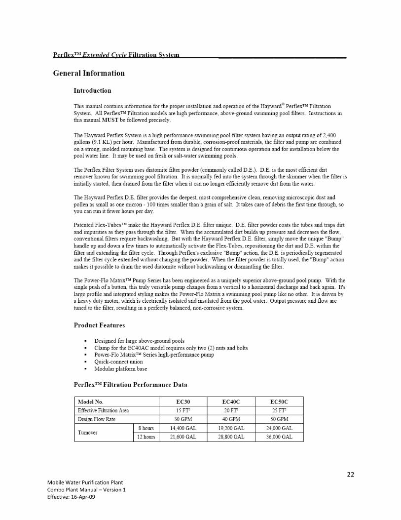
6.2 D.E. Filter Maintenance Filters utilizing diatomite filter powder (commonly called D.E. filters) are known to be very efficient dirt
filters. The filter can be regenerated and cleaned in-line. When the pressure rises 7 – 10 psi (0.5 – 0.7
Bar) above the precoat pressure, regenerate (or “bump”) the filter. Stop the pump; move the “bump”
handle down slowly. Then up briskly. Repeat 3 – 4 times. Restart the pump and filtration will resume at
near the original flow and pressure.
Cleaning of the filter is required when the gauge pressure rises more than 10 psi 90.7 Bar) in less than
24hours of operation or when cloudy water is produced from the filter. To clean, first stop the pump;
then move the bump handle down slowly, and then up briskly. Repeat 8 times. Open the vent valve
(under bump cover), open the filter drain and allow water and dirt to empty completely. Close the drain
and the vent valves; open the suction and return valves. Start pump and let the filter fill with water and
repeat the CLEANING procedure once more. The filter is now ready for recharging. Proceed with the
start-up and PRECOATING procedure as specified on page 7 above.
6.3 Purification Media & Carbon Filters He estimated capacity of the purification and carbon media is 500,000 gal (1,890 m3) of treated water.
Every 500,000 gallons registered in the totalizing water meter both the purification media and the
activated carbon tanks need to be re-bedded with new media. Contact factory to obtain the media.
6.4 Final Filter Maintenance This filter contains a high capacity, high flow pulverized carbon filter cartridge. Typically when the
system is in operation you may not be able to see any significant pressure reading on the pressure gauge
on top of the filter housing if you are flowing to atmospheric pressure. If you notice after replacement
and maintenance of the two pre-filters that the product flow is significant you should take out the final
filter cartridge and scrape the outer layer and flush with fresh water. It is recommended to do this after
every use. Replace the cartridge if necessary or at least every 500,000 gallons of product water when
the purification and carbon media are replaced.
12 Mobile Water Purification Plant Combo Plant Manual – Version 1 Effective: 16-Apr-09
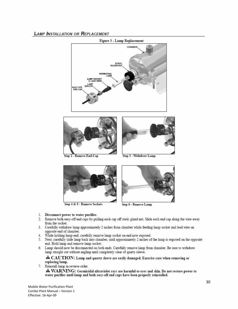
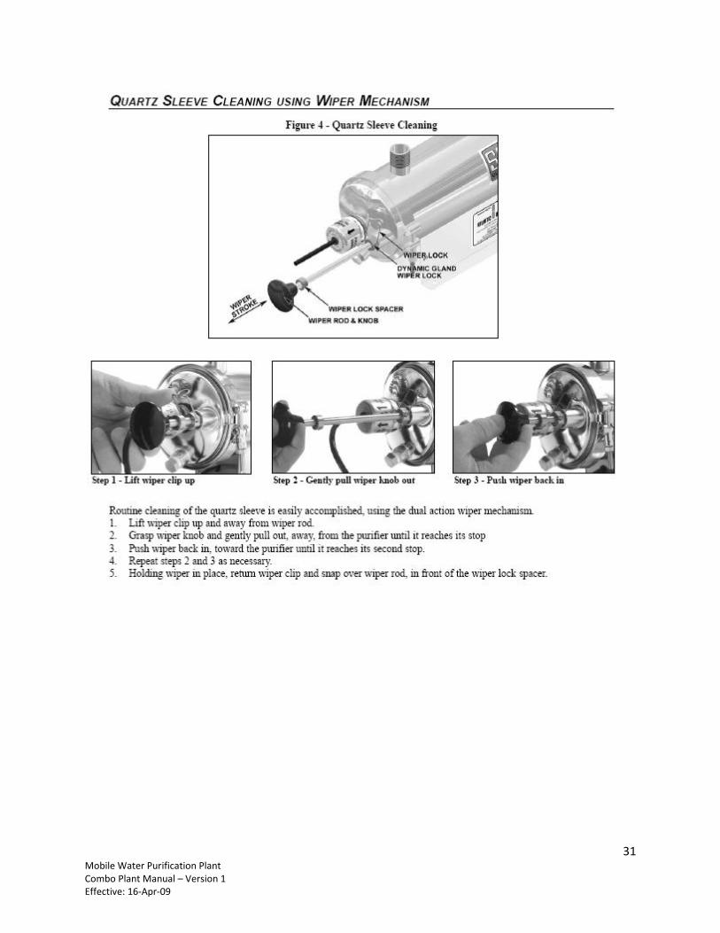
6.5 UV Light sterilizer Maintenance Minimal maintenance is required. Clean the quartz sleeve with the build in wiper assembly by pumping
the wiper in and out 3-4 times before and after every use. Replace the lamp and the quartz sleeve every
10,000 hours of operation (12-months) or every 500,000 gallons of treated water whatever occurs first.
Refer to the UV manual (Appendix 4) for details on the UV sterilizer system.
6.6 General Maintenance Always drain the system completely between every use and before the trailer is transported from one
location to another. Do not transport with system full of water. Always drain thoroughly and clean the
system up if it will be subject to extreme conditions of high temperature or freezing for a prolong period
of time. The system shall be stored and kept ideally at ambient temperatures.
Please see the manuals in the Appendix section of this manual for specific operating & maintenance
details and spare parts for the various components.
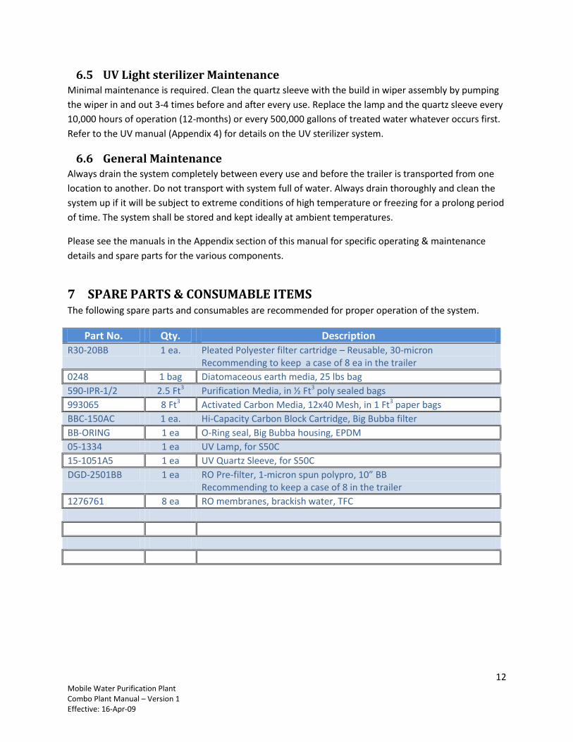
7 SPARE PARTS & CONSUMABLE ITEMS The following spare parts and consumables are recommended for proper operation of the system.
Part No. Qty. Description
R30-20BB 1 ea. Pleated Polyester filter cartridge – Reusable, 30-micron Recommending to keep a case of 8 ea in the trailer
0248 1 bag Diatomaceous earth media, 25 lbs bag
590-IPR-1/2 2.5 Ft3 Purification Media, in ½ Ft3 poly sealed bags
993065 8 Ft3 Activated Carbon Media, 12x40 Mesh, in 1 Ft3 paper bags
BBC-150AC 1 ea. Hi-Capacity Carbon Block Cartridge, Big Bubba filter
BB-ORING 1 ea O-Ring seal, Big Bubba housing, EPDM
05-1334 1 ea UV Lamp, for S50C
15-1051A5 1 ea UV Quartz Sleeve, for S50C
DGD-2501BB 1 ea RO Pre-filter, 1-micron spun polypro, 10” BB Recommending to keep a case of 8 in the trailer
1276761 8 ea RO membranes, brackish water, TFC
13 Mobile Water Purification Plant Combo Plant Manual – Version 1 Effective: 16-Apr-09
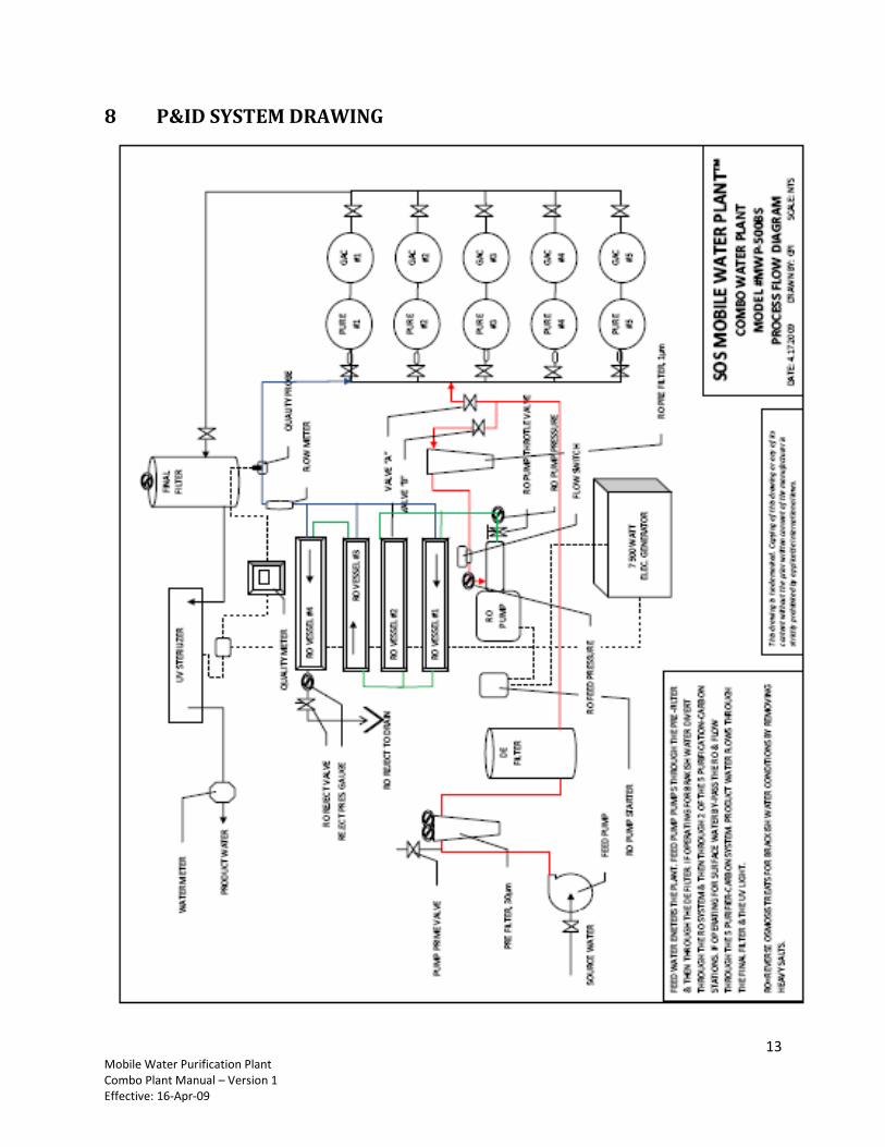
8 P&ID SYSTEM DRAWING
14 Mobile Water Purification Plant Combo Plant Manual – Version 1 Effective: 16-Apr-09
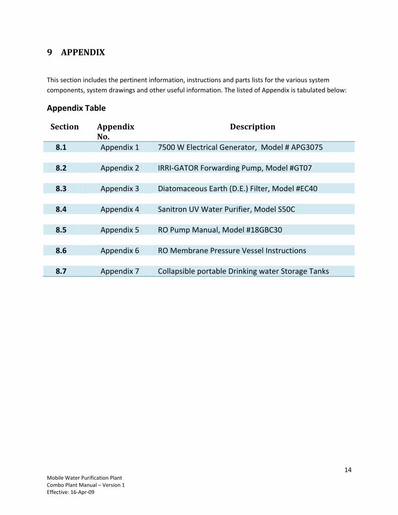
9 APPENDIX
This section includes the pertinent information, instructions and parts lists for the various system
components, system drawings and other useful information. The listed of Appendix is tabulated below:
Appendix Table
Section Appendix No.
Description
8.1 Appendix 1 7500 W Electrical Generator, Model # APG3075
8.2 Appendix 2 IRRI-GATOR Forwarding Pump, Model #GT07
8.3 Appendix 3 Diatomaceous Earth (D.E.) Filter, Model #EC40
8.4 Appendix 4 Sanitron UV Water Purifier, Model S50C
8.5 Appendix 5 RO Pump Manual, Model #18GBC30
8.6 Appendix 6 RO Membrane Pressure Vessel Instructions
8.7 Appendix 7 Collapsible portable Drinking water Storage Tanks

15 Mobile Water Purification Plant Combo Plant Manual – Version 1 Effective: 16-Apr-09
9.1 Appendix 1: 7500 Watt Electrical Generator, Model #APG3075
16 Mobile Water Purification Plant Combo Plant Manual – Version 1 Effective: 16-Apr-09
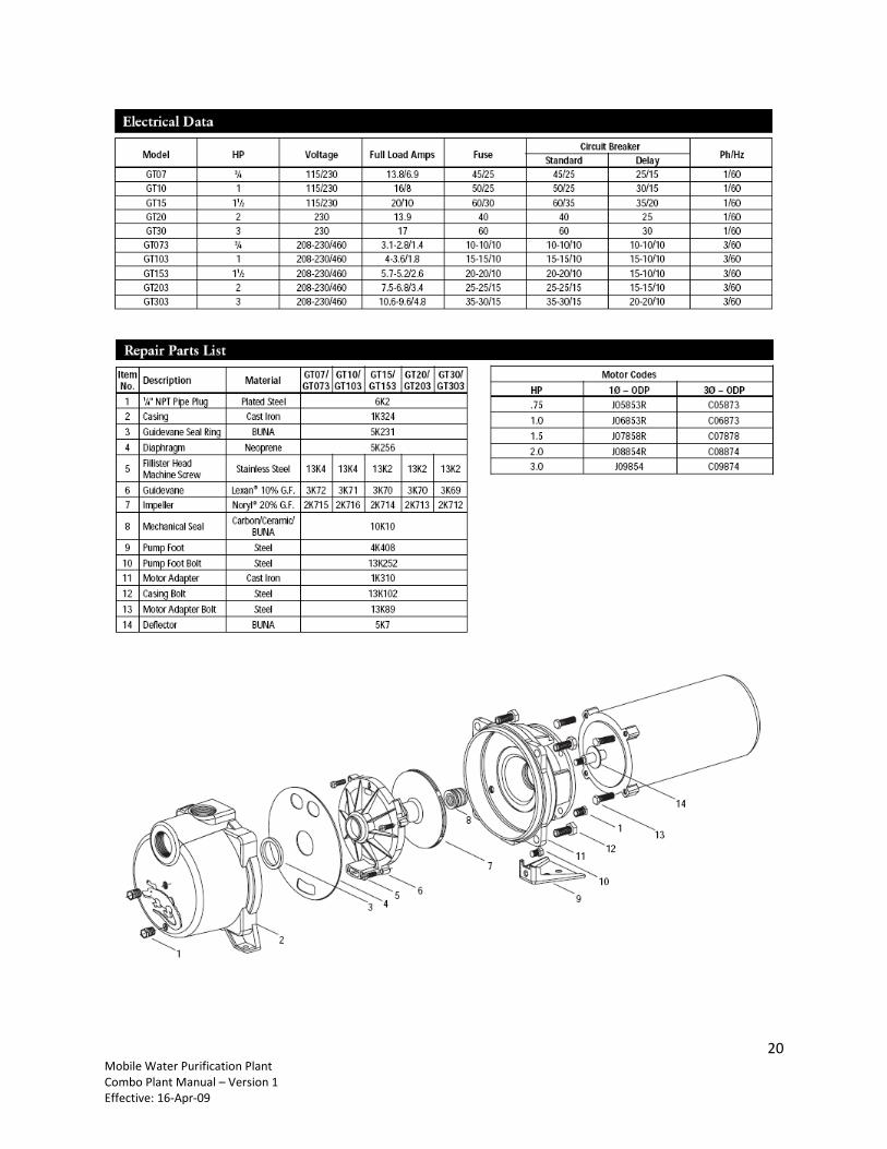
9.2 Appendix 2: IRRI-GATOR Forwarding Pump, Model #GT07
17 Mobile Water Purification Plant Combo Plant Manual – Version 1 Effective: 16-Apr-09
18 Mobile Water Purification Plant Combo Plant Manual – Version 1 Effective: 16-Apr-09
19 Mobile Water Purification Plant Combo Plant Manual – Version 1 Effective: 16-Apr-09
20 Mobile Water Purification Plant Combo Plant Manual – Version 1 Effective: 16-Apr-09
21 Mobile Water Purification Plant Combo Plant Manual – Version 1 Effective: 16-Apr-09
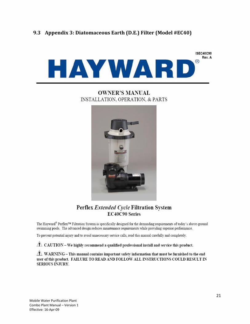
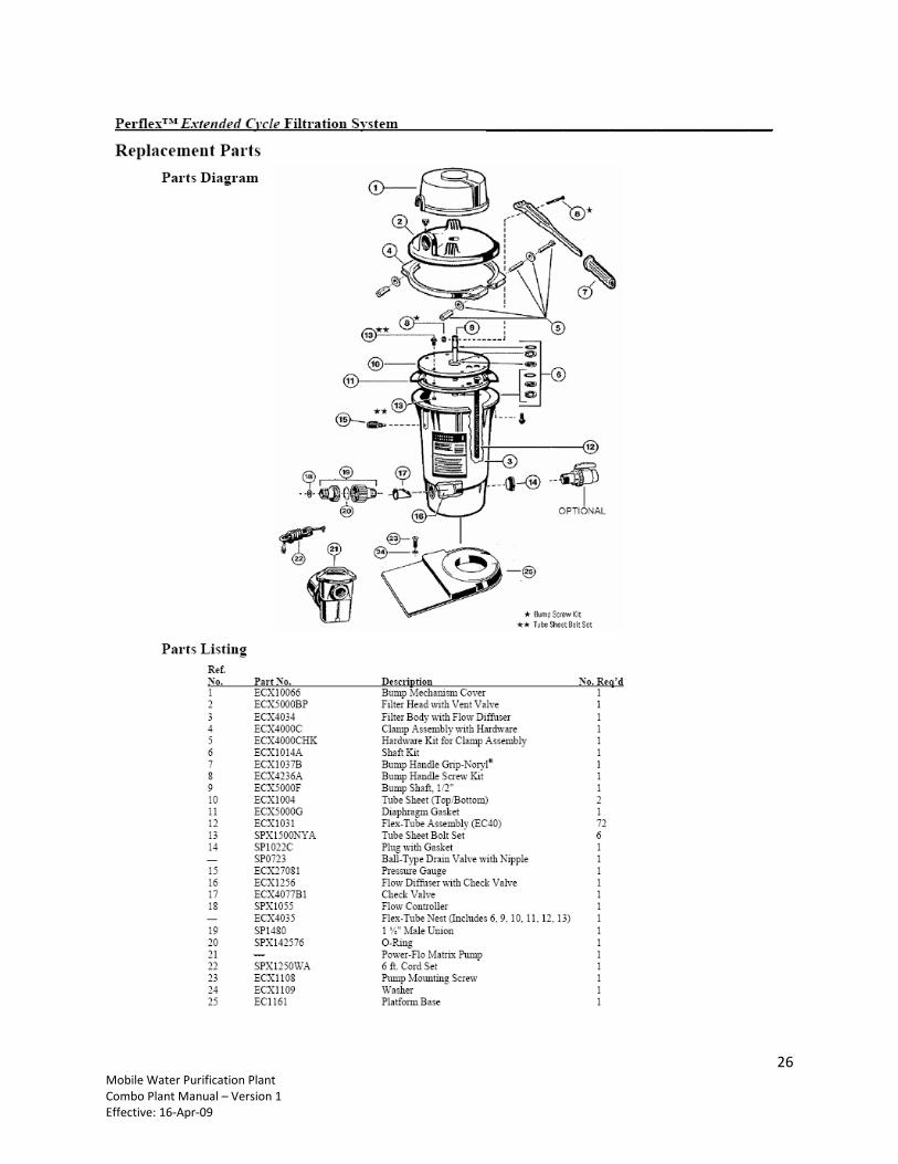
9.3 Appendix 3: Diatomaceous Earth (D.E.) Filter (Model #EC40)
22 Mobile Water Purification Plant Combo Plant Manual – Version 1 Effective: 16-Apr-09
23 Mobile Water Purification Plant Combo Plant Manual – Version 1 Effective: 16-Apr-09
24 Mobile Water Purification Plant Combo Plant Manual – Version 1 Effective: 16-Apr-09
25 Mobile Water Purification Plant Combo Plant Manual – Version 1 Effective: 16-Apr-09
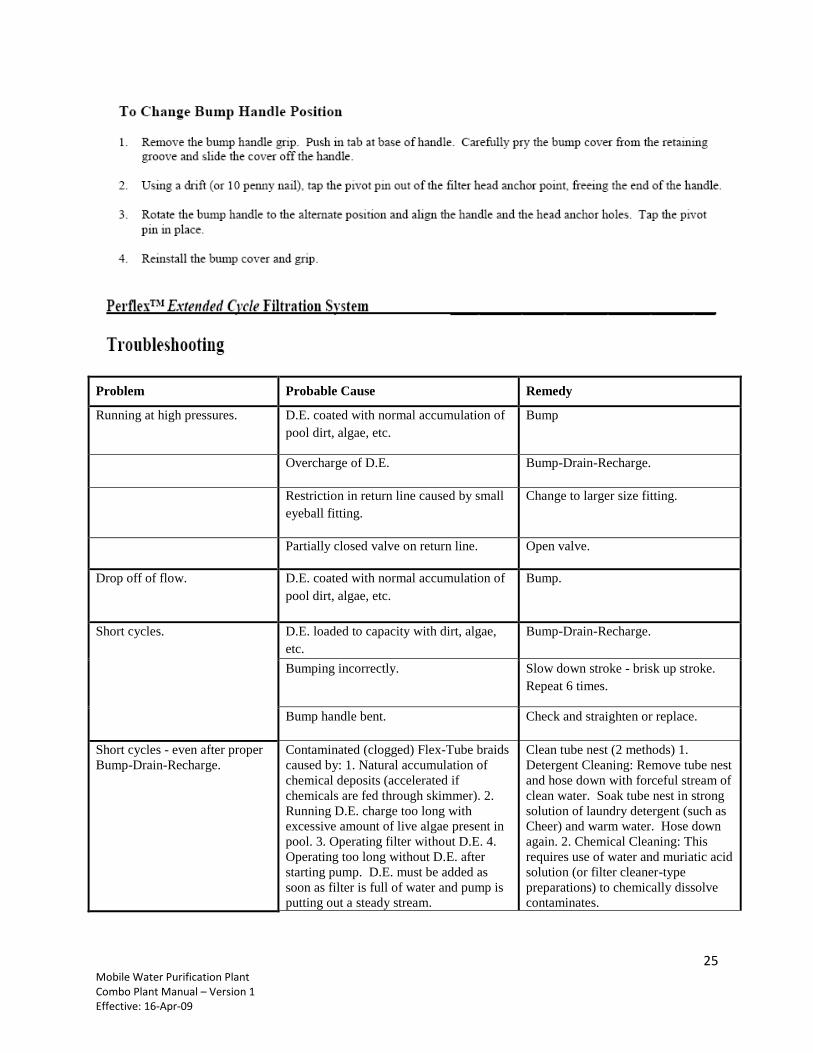
Problem Probable Cause Remedy
Running at high pressures. D.E. coated with normal accumulation of
pool dirt, algae, etc.
Bump
Overcharge of D.E. Bump-Drain-Recharge.
Restriction in return line caused by small
eyeball fitting.
Change to larger size fitting.
Partially closed valve on return line. Open valve.
Drop off of flow. D.E. coated with normal accumulation of
pool dirt, algae, etc.
Bump.
Short cycles. D.E. loaded to capacity with dirt, algae,
etc.
Bump-Drain-Recharge.
Bumping incorrectly. Slow down stroke - brisk up stroke.
Repeat 6 times.
Bump handle bent. Check and straighten or replace.
Short cycles - even after proper
Bump-Drain-Recharge.
Contaminated (clogged) Flex-Tube braids
caused by: 1. Natural accumulation of
chemical deposits (accelerated if
chemicals are fed through skimmer). 2.
Running D.E. charge too long with
excessive amount of live algae present in
pool. 3. Operating filter without D.E. 4.
Operating too long without D.E. after
starting pump. D.E. must be added as
soon as filter is full of water and pump is
putting out a steady stream.
Clean tube nest (2 methods) 1.
Detergent Cleaning: Remove tube nest
and hose down with forceful stream of
clean water. Soak tube nest in strong
solution of laundry detergent (such as
Cheer) and warm water. Hose down
again. 2. Chemical Cleaning: This
requires use of water and muriatic acid
solution (or filter cleaner-type
preparations) to chemically dissolve
contaminates.
26 Mobile Water Purification Plant Combo Plant Manual – Version 1 Effective: 16-Apr-09
27 Mobile Water Purification Plant Combo Plant Manual – Version 1 Effective: 16-Apr-09
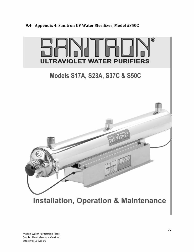
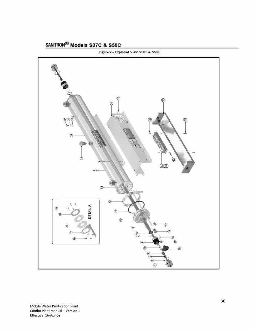
9.4 Appendix 4: Sanitron UV Water Sterilizer, Model #S50C
28 Mobile Water Purification Plant Combo Plant Manual – Version 1 Effective: 16-Apr-09
29 Mobile Water Purification Plant Combo Plant Manual – Version 1 Effective: 16-Apr-09
Effectively treating water with higher concentration levels than listed above can be accomplished, but may require
added measures to improve water quality to treatable levels. If, for any reason, it is believed the ultraviolet
transmission is not satisfactory, contact the factory.
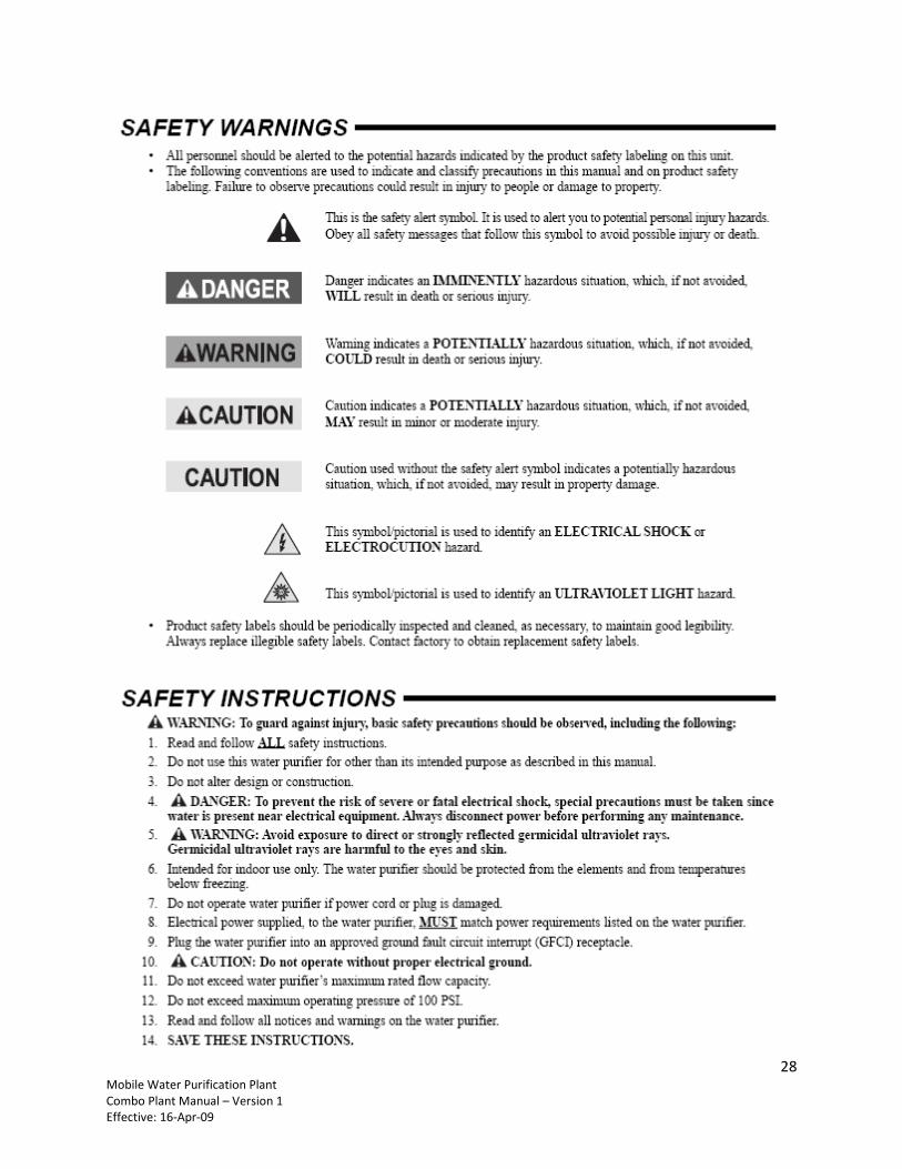
PRODUCT APPLICATION
CONSTRUCTION
• The water purifier is designed to mount horizontally.
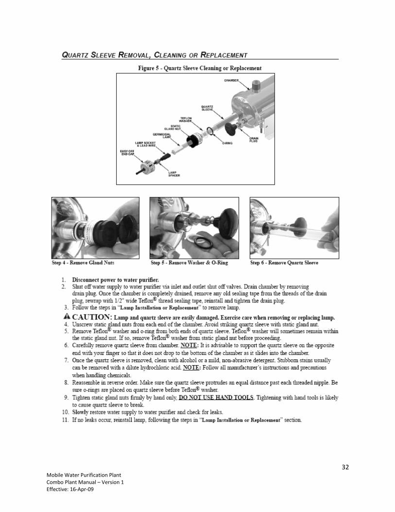
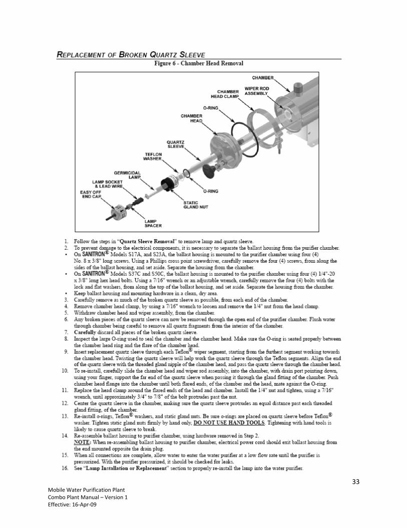
• The water purifier’s removable chamber head design allows for ease of maintenance. A drain port on the
chamber aids in draining of the purifier.
• The water purifier’s chamber and chamber head are passivated and electropolished type 316 Stainless Steel.
• The ballast housing is a combination of Stainless Steel Type 304 and Aluminum Alloy.
• Coated chambers are available for uses with special applications, consult Factory.
• The dual action wiper mechanism allows for quick and easy quartz sleeve cleaning, without interrupting
service.
• Easy-offTM
end caps allow for quick and easy lamp change, without disconnecting from the water supply or
draining the purifier. No tools are required.
PRINCIPLE OF OPERATION
The SANITRON®
design has been carefully conceived to provide adequate germicidal dosage throughout the disin-
fection chamber. The dosage, as it applies to ultraviolet disinfection, is a function of time and the intensity of ultraviolet
radiation to which the water is exposed. The exposure time, in seconds, is the total time it takes the water to flow through
the disinfection chamber exposing it to the germicidal lamp. Exposure time is related to the flow rate; the higher the flow
rate, the lower the exposure time or the lower the flow rate, the higher the exposure time. The ultraviolet intensity is the
amount of energy, per unit time, emitted by the germicidal lamp. The dosage is the product of ultraviolet intensity and
the exposure time. The operation of the SANITRON®
is as follows: 1. Water enters the purifier and flows into the annular space between the quartz sleeve and the chamber wall.
2. Suspended microorganisms are exposed to the ultraviolet rays emitted by the germicidal lamp.
3. The translucent sight port, or optional ultraviolet monitor, provides visual indication of germicidal lamp
operation.
4. The dual action wiper mechanism facilitates periodic cleaning of the quartz sleeve without disassembly or
interruption of purifier operation.
5. Water leaving the purifier is instantly ready for use, no further contact time is required.
LIMITATION OF USE
The water purifier is intended for the use with visually clear water, not colored, cloudy or turbid. See “Water Quality”
section below. The water purifier is NOT intended for the treatment of water that has an obvious contamination or
intentional source, such as raw sewage; nor is the unit intended to convert wastewater to microbiologically safe
drinking water.
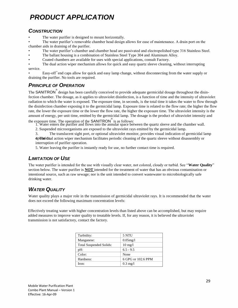
WATER QUALITY
Water quality plays a major role in the transmission of germicidal ultraviolet rays. It is recommended that the water
does not exceed the following maximum concentration levels:
Turbidity: 5 NTU
Manganese: 0.05mg/l
Total Suspended Solids: 10 mg/l
pH: 6.5 - 9.5
Color: None
Hardness: 6 GPG or 102.6 PPM
Iron: 0.3 mg/l
30 Mobile Water Purification Plant Combo Plant Manual – Version 1 Effective: 16-Apr-09
31 Mobile Water Purification Plant Combo Plant Manual – Version 1 Effective: 16-Apr-09
32 Mobile Water Purification Plant Combo Plant Manual – Version 1 Effective: 16-Apr-09
33 Mobile Water Purification Plant Combo Plant Manual – Version 1 Effective: 16-Apr-09
34 Mobile Water Purification Plant Combo Plant Manual – Version 1 Effective: 16-Apr-09
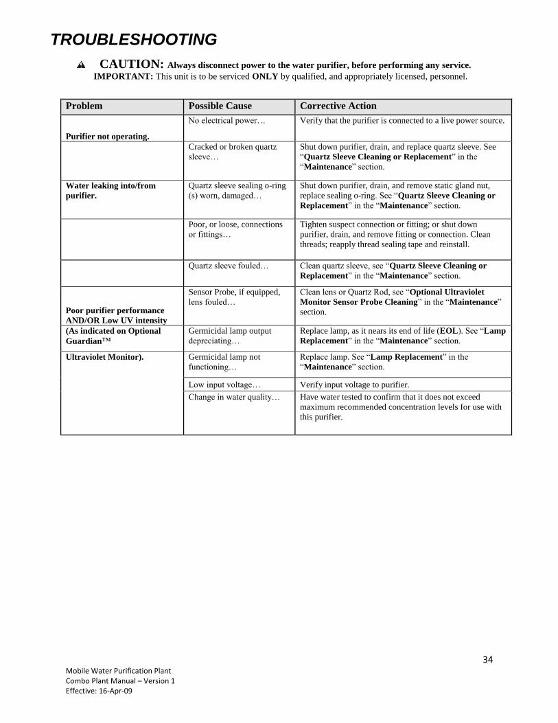
Problem Possible Cause Corrective Action
Purifier not operating.
No electrical power… Verify that the purifier is connected to a live power source.
Cracked or broken quartz
sleeve…
Shut down purifier, drain, and replace quartz sleeve. See
“Quartz Sleeve Cleaning or Replacement” in the
“Maintenance” section.
Water leaking into/from
purifier.
Quartz sleeve sealing o-ring
(s) worn, damaged…
Shut down purifier, drain, and remove static gland nut,
replace sealing o-ring. See “Quartz Sleeve Cleaning or
Replacement” in the “Maintenance” section.
Poor, or loose, connections
or fittings…
Tighten suspect connection or fitting; or shut down
purifier, drain, and remove fitting or connection. Clean
threads; reapply thread sealing tape and reinstall.
Quartz sleeve fouled… Clean quartz sleeve, see “Quartz Sleeve Cleaning or
Replacement” in the “Maintenance” section.
Poor purifier performance
AND/OR Low UV intensity
Sensor Probe, if equipped,
lens fouled…
Clean lens or Quartz Rod, see “Optional Ultraviolet
Monitor Sensor Probe Cleaning” in the “Maintenance”
section.
(As indicated on Optional
Guardian™ Germicidal lamp output
depreciating…
Replace lamp, as it nears its end of life (EOL). See “Lamp
Replacement” in the “Maintenance” section.
Ultraviolet Monitor). Germicidal lamp not
functioning…
Replace lamp. See “Lamp Replacement” in the
“Maintenance” section.
Low input voltage… Verify input voltage to purifier.
Change in water quality… Have water tested to confirm that it does not exceed
maximum recommended concentration levels for use with
this purifier.
TROUBLESHOOTING
! CAUTION: Always disconnect power to the water purifier, before performing any service.
IMPORTANT: This unit is to be serviced ONLY by qualified, and appropriately licensed, personnel.
35 Mobile Water Purification Plant Combo Plant Manual – Version 1 Effective: 16-Apr-09
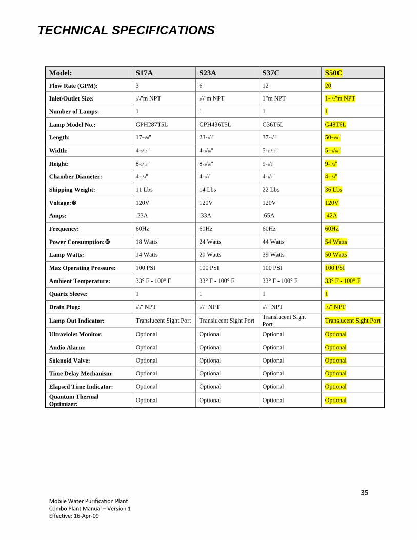
Model: S17A S23A S37C S50C
Flow Rate (GPM): 3 6 12 20
Inlet\Outlet Size: 3/4"m NPT 3/4"m NPT 1"m NPT 1-1/2"m NPT
Number of Lamps: 1 1 1 1
Lamp Model No.: GPH287T5L GPH436T5L G36T6L G48T6L
Length: 17-3/8" 23-3/8" 37-3/8" 50-3/8"
Width: 4-5/16" 4-5/16" 5-11/16" 5-11/16"
Height: 8-3/16" 8-3/16" 9-1/2" 9-1/2"
Chamber Diameter: 4-1/4" 4-1/4" 4-1/4" 4-1/4"
Shipping Weight: 11 Lbs 14 Lbs 22 Lbs 36 Lbs
Voltage: 120V 120V 120V 120V
Amps: .23A .33A .65A .42A
Frequency: 60Hz 60Hz 60Hz 60Hz
Power Consumption: 18 Watts 24 Watts 44 Watts 54 Watts
Lamp Watts: 14 Watts 20 Watts 39 Watts 50 Watts
Max Operating Pressure: 100 PSI 100 PSI 100 PSI 100 PSI
Ambient Temperature: 33° F - 100° F 33° F - 100° F 33° F - 100° F 33° F - 100° F
Quartz Sleeve: 1 1 1 1
Drain Plug: 1/4" NPT 1/4" NPT 1/4" NPT 1/4" NPT
Lamp Out Indicator: Translucent Sight Port Translucent Sight Port Translucent Sight
Port Translucent Sight Port
Ultraviolet Monitor: Optional Optional Optional Optional
Audio Alarm: Optional Optional Optional Optional
Solenoid Valve: Optional Optional Optional Optional
Time Delay Mechanism: Optional Optional Optional Optional
Elapsed Time Indicator: Optional Optional Optional Optional
Quantum Thermal
Optimizer: Optional Optional Optional Optional
TECHNICAL SPECIFICATIONS
36 Mobile Water Purification Plant Combo Plant Manual – Version 1 Effective: 16-Apr-09
37 Mobile Water Purification Plant Combo Plant Manual – Version 1 Effective: 16-Apr-09
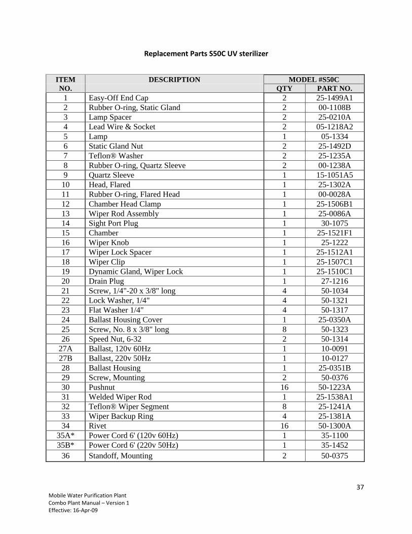
Replacement Parts S50C UV sterilizer
ITEM DESCRIPTION MODEL #S50C
NO. QTY PART NO.
1 Easy-Off End Cap 2 25-1499A1
2 Rubber O-ring, Static Gland 2 00-1108B
3 Lamp Spacer 2 25-0210A
4 Lead Wire & Socket 2 05-1218A2
5 Lamp 1 05-1334
6 Static Gland Nut 2 25-1492D
7 Teflon® Washer 2 25-1235A
8 Rubber O-ring, Quartz Sleeve 2 00-1238A
9 Quartz Sleeve 1 15-1051A5
10 Head, Flared 1 25-1302A
11 Rubber O-ring, Flared Head 1 00-0028A
12 Chamber Head Clamp 1 25-1506B1
13 Wiper Rod Assembly 1 25-0086A
14 Sight Port Plug 1 30-1075
15 Chamber 1 25-1521F1
16 Wiper Knob 1 25-1222
17 Wiper Lock Spacer 1 25-1512A1
18 Wiper Clip 1 25-1507C1
19 Dynamic Gland, Wiper Lock 1 25-1510C1
20 Drain Plug 1 27-1216
21 Screw, 1/4"-20 x 3/8" long 4 50-1034
22 Lock Washer, 1/4" 4 50-1321
23 Flat Washer 1/4" 4 50-1317
24 Ballast Housing Cover 1 25-0350A
25 Screw, No. 8 x 3/8" long 8 50-1323
26 Speed Nut, 6-32 2 50-1314
27A Ballast, 120v 60Hz 1 10-0091
27B Ballast, 220v 50Hz 1 10-0127
28 Ballast Housing 1 25-0351B
29 Screw, Mounting 2 50-0376
30 Pushnut 16 50-1223A
31 Welded Wiper Rod 1 25-1538A1
32 Teflon® Wiper Segment 8 25-1241A
33 Wiper Backup Ring 4 25-1381A
34 Rivet 16 50-1300A
35A* Power Cord 6' (120v 60Hz) 1 35-1100
35B* Power Cord 6' (220v 50Hz) 1 35-1452
36 Standoff, Mounting 2 50-0375
38 Mobile Water Purification Plant Combo Plant Manual – Version 1 Effective: 16-Apr-09
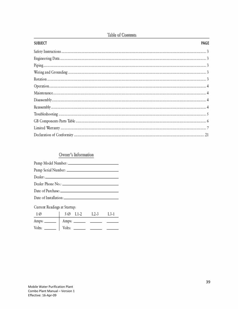
9.5 Appendix 5: RO Pump Manual Model #18GBC30
39 Mobile Water Purification Plant Combo Plant Manual – Version 1 Effective: 16-Apr-09
40 Mobile Water Purification Plant Combo Plant Manual – Version 1 Effective: 16-Apr-09
41 Mobile Water Purification Plant Combo Plant Manual – Version 1 Effective: 16-Apr-09
42 Mobile Water Purification Plant Combo Plant Manual – Version 1 Effective: 16-Apr-09
43 Mobile Water Purification Plant Combo Plant Manual – Version 1 Effective: 16-Apr-09
44 Mobile Water Purification Plant Combo Plant Manual – Version 1 Effective: 16-Apr-09
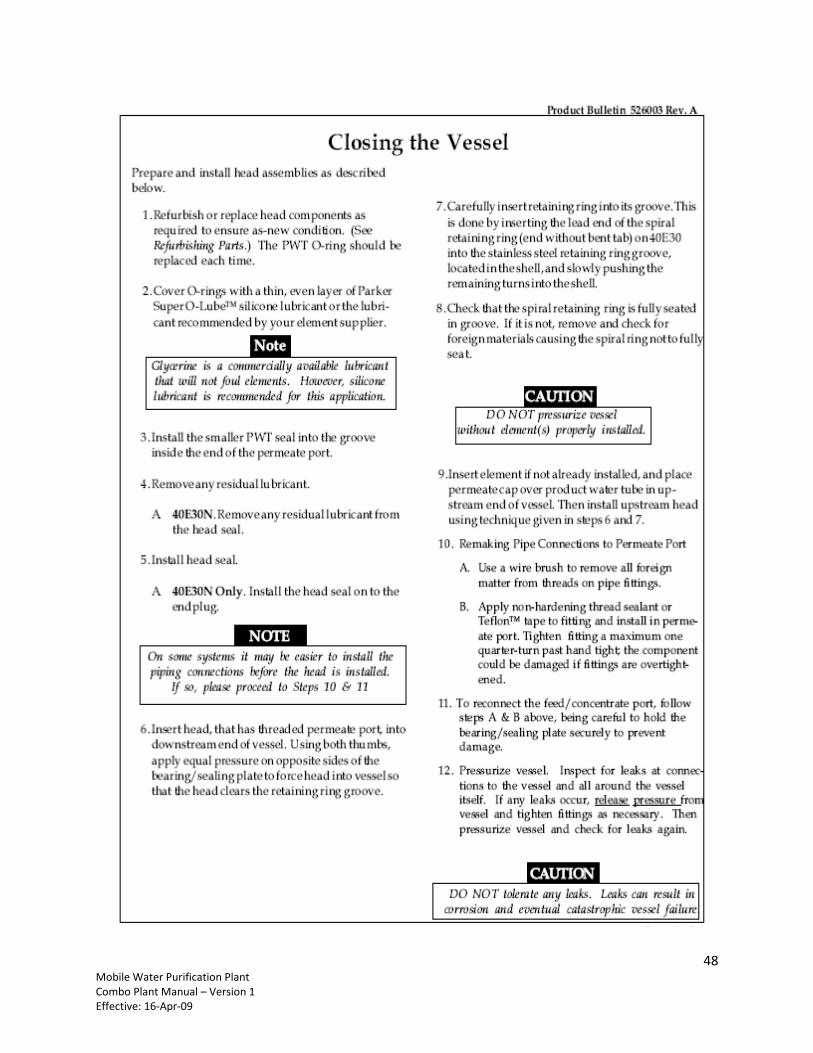
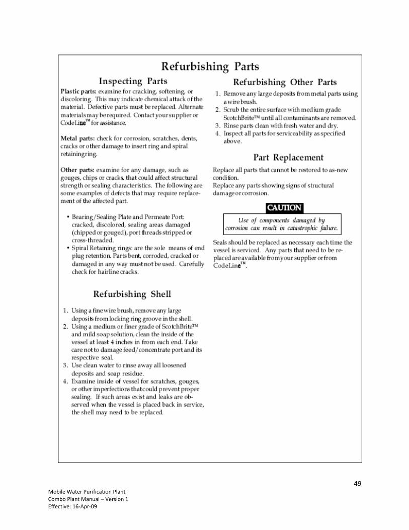
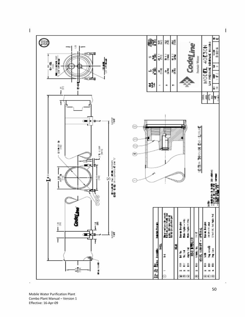
9.6 Appendix 6: RO Membranes Pressure Vessel Instructions
45 Mobile Water Purification Plant Combo Plant Manual – Version 1 Effective: 16-Apr-09
46 Mobile Water Purification Plant Combo Plant Manual – Version 1 Effective: 16-Apr-09
47 Mobile Water Purification Plant Combo Plant Manual – Version 1 Effective: 16-Apr-09
48 Mobile Water Purification Plant Combo Plant Manual – Version 1 Effective: 16-Apr-09
49 Mobile Water Purification Plant Combo Plant Manual – Version 1 Effective: 16-Apr-09
50 Mobile Water Purification Plant Combo Plant Manual – Version 1 Effective: 16-Apr-09
51 Mobile Water Purification Plant Combo Plant Manual – Version 1 Effective: 16-Apr-09
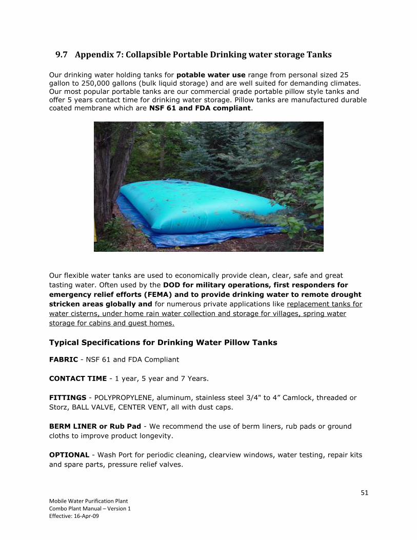
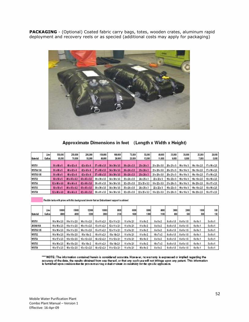
9.7 Appendix 7: Collapsible Portable Drinking water storage Tanks
Our drinking water holding tanks for potable water use range from personal sized 25
gallon to 250,000 gallons (bulk liquid storage) and are well suited for demanding climates.
Our most popular portable tanks are our commercial grade portable pillow style tanks and
offer 5 years contact time for drinking water storage. Pillow tanks are manufactured durable coated membrane which are NSF 61 and FDA compliant.
Our flexible water tanks are used to economically provide clean, clear, safe and great
tasting water. Often used by the DOD for military operations, first responders for
emergency relief efforts (FEMA) and to provide drinking water to remote drought
stricken areas globally and for numerous private applications like replacement tanks for
water cisterns, under home rain water collection and storage for villages, spring water
storage for cabins and guest homes.
Typical Specifications for Drinking Water Pillow Tanks
FABRIC - NSF 61 and FDA Compliant
CONTACT TIME - 1 year, 5 year and 7 Years.
FITTINGS - POLYPROPYLENE, aluminum, stainless steel 3/4" to 4” Camlock, threaded or
Storz, BALL VALVE, CENTER VENT, all with dust caps.
BERM LINER or Rub Pad - We recommend the use of berm liners, rub pads or ground
cloths to improve product longevity.
OPTIONAL - Wash Port for periodic cleaning, clearview windows, water testing, repair kits
and spare parts, pressure relief valves.
52 Mobile Water Purification Plant Combo Plant Manual – Version 1 Effective: 16-Apr-09
PACKAGING - (Optional) Coated fabric carry bags, totes, wooden crates, aluminum rapid deployment and recovery reels or as specied (additional costs may apply for packaging)