Embed Size (px)
Citation preview
Page 1 of 15
Date Created: March 29, 2004 Date Modified:
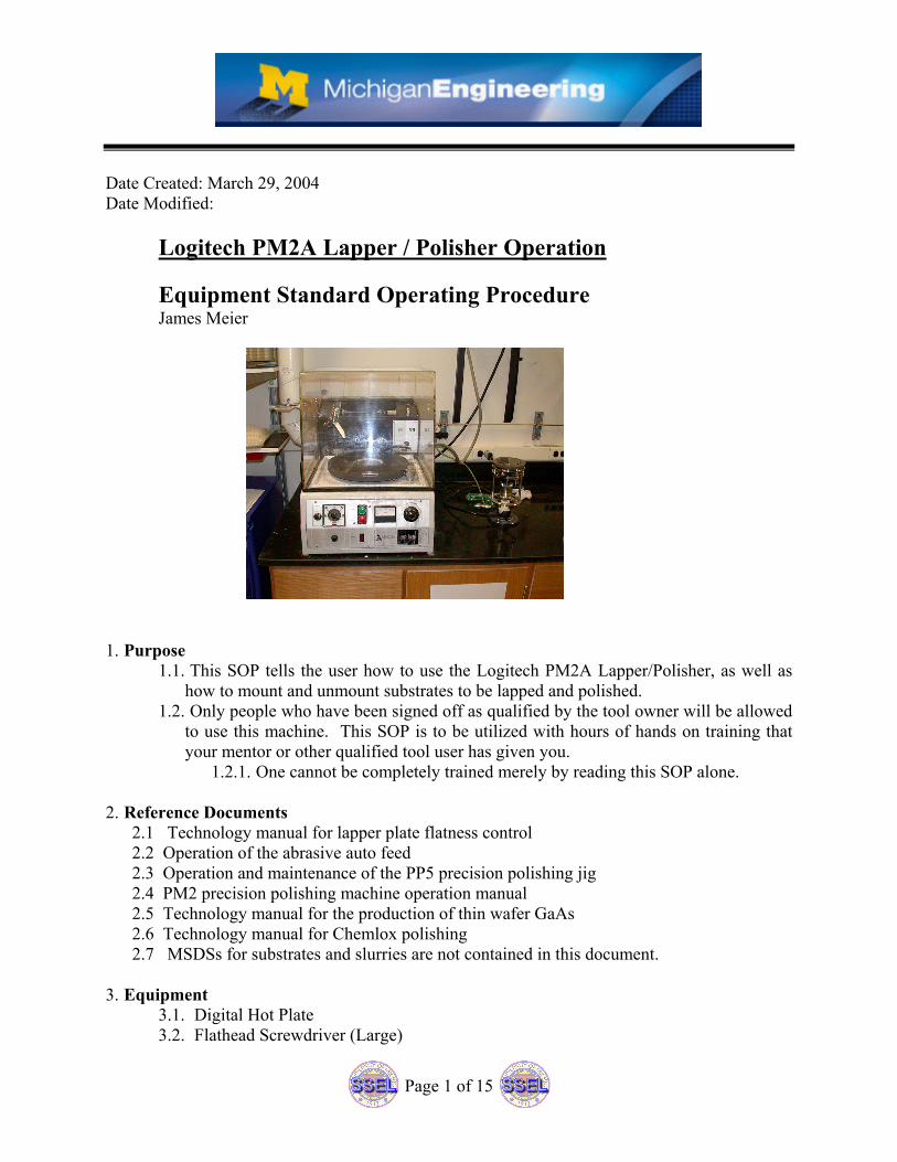
Logitech PM2A Lapper / Polisher Operation
Equipment Standard Operating Procedure James Meier
1. Purpose
1.1. This SOP tells the user how to use the Logitech PM2A Lapper/Polisher, as well as how to mount and unmount substrates to be lapped and polished.
1.2. Only people who have been signed off as qualified by the tool owner will be allowed to use this machine. This SOP is to be utilized with hours of hands on training that your mentor or other qualified tool user has given you.
1.2.1. One cannot be completely trained merely by reading this SOP alone.
2. Reference Documents 2.1 Technology manual for lapper plate flatness control 2.2 Operation of the abrasive auto feed 2.3 Operation and maintenance of the PP5 precision polishing jig 2.4 PM2 precision polishing machine operation manual 2.5 Technology manual for the production of thin wafer GaAs 2.6 Technology manual for Chemlox polishing 2.7 MSDSs for substrates and slurries are not contained in this document.
3. Equipment
3.1. Digital Hot Plate 3.2. Flathead Screwdriver (Large)
Page 2 of 15
3.3. Funnel 3.4. Garbage Bags 3.5. Glass Carrier 3.6. Kim Wipes 3.7. Logitech PM2A Lapper/Polisher 3.8. Micrometer 3.9. N2 Gun 3.10. Razor Blade 3.11. Swabs 3.12. Teflon Tweezers
4. Materials
4.1. 1827 Photo resist 4.2. 3um Grit Slurry (calcined aluminum oxide in DI water) 4.3. 9um Grit Slurry (calcined aluminum oxide in DI water) 4.4. Acetone 4.5. DI Water 4.6. Eco Clear 4.7. Glycol Phthalate (crystal wax) 4.8. IPA 4.9. Paraffin Wax 4.10. PRS-1000 4.11. Quartz Wax 4.12. SF1 Polishing solution 4.13. NOTE: MSDSs for above chemicals are NOT in this document. Also consult the
MSDS for the substrate you are lapping.
5. Protective Equipment 5.1. Use protective gloves and safety glasses when lapping/polishing. A facemask can
also be worn to reduce the amount of grit and dried slurry waste inhaled. Trace amounts of Arsenic have been found on surfaces in the lapping room.
5.2. A facemask should be worn when dispensing 3um and 9um calcined aluminum oxide.
5.3. User may want to wear a lab coat and shoe covers to protect clothing. 5.4. Wear required garments for Clean Room and Chem. Room. 5.5. Wash hands when you are finished.
6. Engineering and/or Administrative Controls
6.1. Only authorized users may use this tool. 6.1.1. This SOP is to be utilized with hours of hands on training that your mentor
or other qualified tool user has given you. One cannot be completely trained merely by reading this SOP alone.
6.2. The tool owner is Terre Briggs, [email protected]. 6.3. The checkout person is James Meier, [email protected]. 6.4. Consult the MSDS of your substrate and slurry.
Page 3 of 15
6.5. The lapping and polishing process shall be done in Room 1335. 6.6. Mounting and unmounting substrates shall be done in the Chem. Room or the Clean
Room. 6.7. The Solvent hood in the Chem. Room should be used when dispensing 3um and
9um calcined aluminum oxide grit into the slurry cylinders. This reduces the amount of grit inhaled.
6.8. The use of Chemlox (a polishing agent) is prohibited on this machine. It will corrode parts and also needs ample ventilation.
6.8.1. Chemlox may be used in the solvent hood of the chem. room. 6.8.2. Ensure you schedule time for the Chem. Room.
6.9. The lapping jig and the lapping wheels are heavy and somewhat hard to hold. If dropped, you can damage the jig, the lapping wheel, whatever they land on (e.g. your toes), or your substrate. We also suspect that rough handling when placing or removing the jig on the lapping wheel causes a lot of damage to the glass-lapping wheel or when the glass-lapping wheel is removed/installed. This is causing the glass on the lapping wheel to chip off.
6.10. This machine has been in production for years. Parts are getting harder to find. 6.11. This equipment costs a lot of money to repair or replace.
7. Procedure
7.1. Definitions 7.1.1. Lapping is the wearing away of material by abrasion from a free flowing
slurry or fixed abrasive pad. It produces a matte surface. 7.1.2. Polishing is the removal of surface damage usually created by lapping to
produce a higher quality surface. It produces a reflective surface.
7.2. Substrate Thickness Measurement
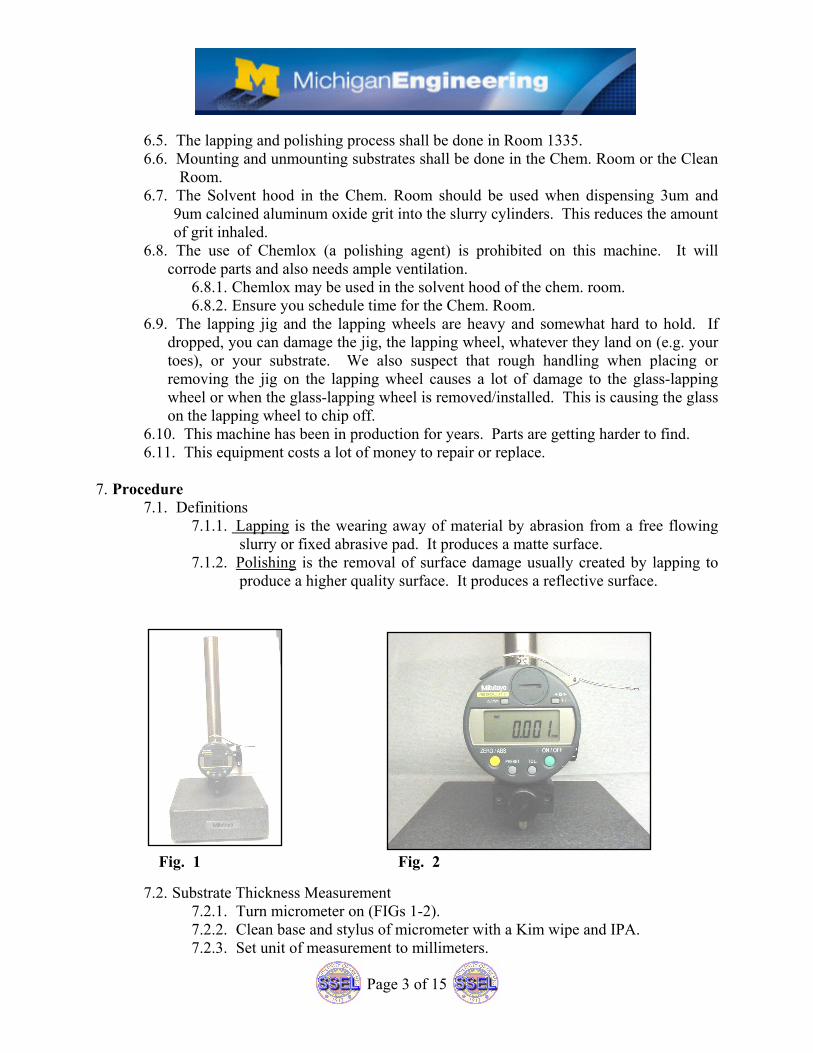
7.2.1. Turn micrometer on (FIGs 1-2). 7.2.2. Clean base and stylus of micrometer with a Kim wipe and IPA. 7.2.3. Set unit of measurement to millimeters.
Fig. 1 Fig. 2
Page 4 of 15
7.2.4. Zero the system. The base should be at zero millimeters. 7.2.5. Place substrate on base and measure several places. 7.2.6. Measure base again to be sure system is still zeroed. 7.2.7. Average the measurements taken.
7.3. Coat Samples with Photo resist (Optional) 7.3.1. Photo resist helps to protect the substrate surface that is face down against
the glass carrier surface. 7.3.2. Follow Photo resist Spinner procedure (suggest using Shipley 1827 at
3000-4000 RPM) to spin on resist. 7.3.3. Soft bake substrate (suggest 3min at 105C).
7.4. Mounting (Low Precision) 7.4.1. Clean a glass carrier using a wipe and acetone. 7.4.2. Inspect both surfaces of the glass carrier for nicks, scratches, etc. The
substrate is mounted on the worst looking side. The side that is most pristine goes against the face of the vacuum chuck on the lapping jig.
7.4.3. Set the hotplate to the appropriate temperature, place the glass carrier on the hotplate, place some wax on the center of the glass carrier, and let melt. 7.4.3.1. Only use as much wax as needed, wax should not be running off
the side of the glass carrier. 7.4.3.2. NOTE: If wax requires a temperature of over 100C, warm up the
glass carrier on an 80C hotplate for 1-2 minutes. This will help to avoid thermal shock, which may crack the glass carrier.
7.4.3.3. Quartz Wax: ~80C. 7.4.3.4. Paraffin: 50-60C. 7.4.3.5. Glycal Phthalate: ~155C.
7.4.4. Only place one substrate per carrier if a precise final thickness is needed. 7.4.5. Place your substrate on the melted wax with the side to be lapped away
facing up (out of the wax) and the side to be preserved facing down (into the wax).
7.4.6. Press down on the substrate with Teflon tweezers and move the substrate back and forth, left and right, rotate, and repeat. This will help to give a uniform thickness to the wax under the substrate.
7.4.7. Do not leave the substrate on the hotplate too long or you could “burn” the photo resist protective layer (if used) making it difficult to remove. This mainly applies to waxes that need 120C or hotter.
7.4.8. Carefully remove the glass carrier from the hotplate (use a wiper as an oven mitt) and place on something metal to cool. Do not use liquids to force cool the glass carrier as the thermal shock might crack the carrier.
7.4.9. After the glass carrier is at room temperature, carefully remove excess wax with a razor blade. Scrape parallel to the substrate edge so you won’t accidentally pop the substrate off the carrier. Leave a small bead of wax around the substrate to protect the edge.
7.4.10. Blow off wax particles with a N2 gun
Page 5 of 15
7.4.11. Clean off wax residue from the glass carrier and the substrate with a swab and the appropriate solvent for the wax you are using.
7.4.12. Turn the carrier over and look for air bubbles under the substrate. If the air bubbles are too many or cover too much area, place carrier on hotplate to repeat mounting procedure.
7.4.13. Measure the mounted substrate thickness on the micrometer and find the average thickness.
7.4.14. Decide if the amount of wedging (the difference between the thickest and thinnest values over the distance between them) is too large. If your wedging is too large, place carrier on hotplate and repeat Steps 7.4.6-7.4.14.
7.4.15. Find the wax thickness by subtracting the initial substrate thickness from the mounted thickness.
Example: Bare substrate thickness: 605um. Mounted substrate thickness: 640um.
Wax Thickness = (640um – 605um) = 35um.
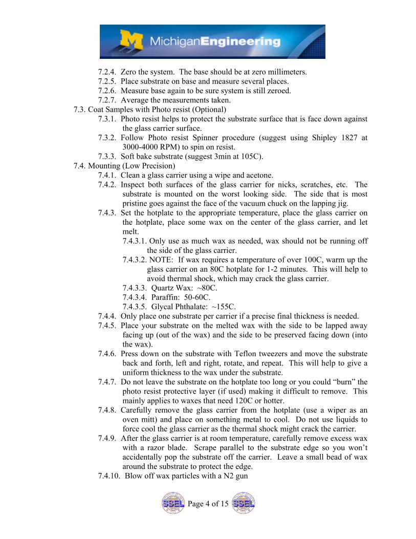
7.5. Filling the Abrasive Feed Cylinder (in Chem. Room Solvent Hood):
7.5.1. FIG. 3 and FIG. 4 shows the 3um abrasive feed cylinder. 7.5.2. Never intermix slurry solutions (e.g. put 9um slurry grit in the 3um slurry
cylinder. Cross contamination will result. 7.5.3. Cylinders with a metal valve are to be used for 3um grit or larger.
7.5.3.1. Never use a metal valve cylinder for Chemlox polishing solution. This type of cylinder is not chemical resistant.
7.5.4. Never dump slurry down the drain, use the slurry waste bucket. 7.5.5. Never shake the cylinder; this motion will clog the valve. 7.5.6. The 3um and 9um slurry solutions are a 10% mix of calcined alumina grit
in DI water. A full cylinder contains 1.5 liters of slurry; 150ml of this is calcined alumina grit. A “FULL” cylinder is actually only filled
Fig. 3 Fig. 4
Filler Plug
Page 6 of 15
halfway to the top (the line around the cylinder). Filling past the halfway mark will cause the slurry to flow out of the cylinder (when installed on the lapper) even when the lapper is off. It can also clog the valve.
7.5.7. Inspect the cylinder for signs of damage. 7.5.8. Place abrasive feed cylinder in fume hood with valve pointing up. 7.5.9. Carefully unscrew filler plug (FIG.4) with flathead screwdriver. 7.5.10. Using a clean funnel, add proper size alumina oxide grit, and then add the
appropriate amount of water. Slurry level should not be above the halfway line on the cylinder.
7.5.11. Clean the threads of the fill plug and fill plughole. Screw the fill plug back into position. Do not over tighten. Slurry should not leak out.
7.5.12. Clean the external surface of cylinder, valves, tools, and equipment. 7.5.13. Slurry should last 4-6 hours between refills at 1-2 drops of slurry per
second.
7.6. Lapping Jig
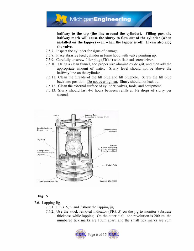
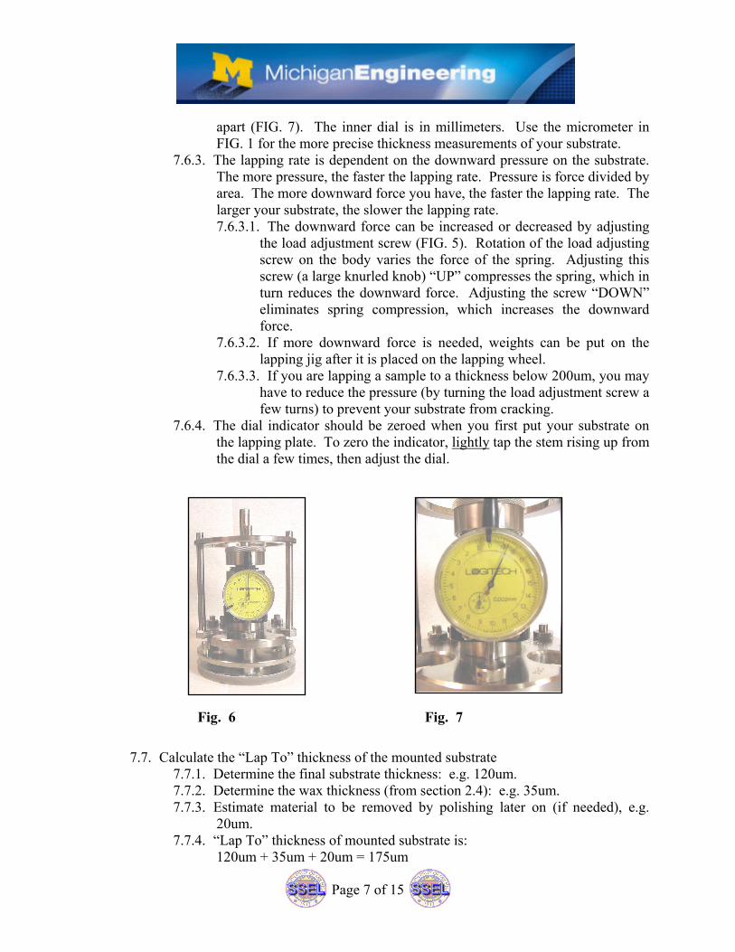
7.6.1. FIGs. 5, 6, and 7 show the lapping jig. 7.6.2. Use the stock removal indicator (FIG. 5) on the jig to monitor substrate
thickness while lapping. On the outer dial: one revolution is 200um, the numbered tick marks are 10um apart, and the small tick marks are 2um
Fig. 5
Page 7 of 15
apart (FIG. 7). The inner dial is in millimeters. Use the micrometer in FIG. 1 for the more precise thickness measurements of your substrate.
7.6.3. The lapping rate is dependent on the downward pressure on the substrate. The more pressure, the faster the lapping rate. Pressure is force divided by area. The more downward force you have, the faster the lapping rate. The larger your substrate, the slower the lapping rate. 7.6.3.1. The downward force can be increased or decreased by adjusting
the load adjustment screw (FIG. 5). Rotation of the load adjusting screw on the body varies the force of the spring. Adjusting this screw (a large knurled knob) “UP” compresses the spring, which in turn reduces the downward force. Adjusting the screw “DOWN” eliminates spring compression, which increases the downward force.
7.6.3.2. If more downward force is needed, weights can be put on the lapping jig after it is placed on the lapping wheel.
7.6.3.3. If you are lapping a sample to a thickness below 200um, you may have to reduce the pressure (by turning the load adjustment screw a few turns) to prevent your substrate from cracking.
7.6.4. The dial indicator should be zeroed when you first put your substrate on the lapping plate. To zero the indicator, lightly tap the stem rising up from the dial a few times, then adjust the dial.
7.7. Calculate the “Lap To” thickness of the mounted substrate 7.7.1. Determine the final substrate thickness: e.g. 120um. 7.7.2. Determine the wax thickness (from section 2.4): e.g. 35um. 7.7.3. Estimate material to be removed by polishing later on (if needed), e.g.
20um. 7.7.4. “Lap To” thickness of mounted substrate is:
120um + 35um + 20um = 175um
Fig. 6 Fig. 7
Page 8 of 15
7.7.5. Get thickness of mounted substrate from Section 7.4. e.g. 640um. 7.7.6. Amount of material to lap away is:
640um – 175um = 465um 7.8. Clean Lapper Before Use (NOT NECESSARY IF PREVIOUS USER DID
HIS/HER JOB AND CLEANED THE SYSTEM AFTER USE). 7.8.1. A clean lapper will prevent your work from being contaminated by a
previous user’s work. An example of this would be if the lapping plate has 9um grit on it and you want to lap with only 3um grit to keep lapping damage to a minimum.
7.8.2. Ensure you are wearing gloves for the clean up. 7.8.3. Use clean wipes and DI water to wipe down system.
7.8.3.1. Place all wipes in the slurry waste trashcan. 7.8.4. Also wipe down surrounding countertops and other surfaces.
7.8.4.1. Wipe down Slurry bucket lid. 7.8.4.2. Wipe down the blue cabinet next to the Lapper. 7.8.4.3. Place wipes in the slurry waste trashcan.
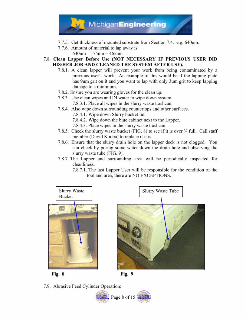
7.8.5. Check the slurry waste bucket (FIG. 8) to see if it is over ¾ full. Call staff member (David Kouba) to replace if it is.
7.8.6. Ensure that the slurry drain hole on the lapper deck is not clogged. You can check by poring some water down the drain hole and observing the slurry waste tube (FIG. 9).
7.8.7. The Lapper and surrounding area will be periodically inspected for cleanliness. 7.8.7.1. The last Lapper User will be responsible for the condition of the
tool and area, there are NO EXCEPTIONS.
7.9. Abrasive Feed Cylinder Operation:
Slurry Waste Bucket
Slurry Waste Tube
Fig. 8 Fig. 9
Page 9 of 15
7.9.1. A “FULL” cylinder is actually only filled halfway to the top (the line around the cylinder). Filling past the halfway mark will cause the slurry to flow out of the cylinder (when installed on the lapper) even when the lapper is off. It can also clog the valve.
7.9.2. Choose the correct slurry grit. 7.9.3. Rotate the adjustment screw on the valve clockwise, until the valve feels
closed. 7.9.4. The zero mark on the cap should roughly align with the reference mark on
the body. 7.9.5. The numerical marks on the cap indicate increments of 1/3 turn. 7.9.6. Do to the valve design; the valve action is not linear. A full turn will give
you a lot more than twice the drip rate of one half turn. 7.9.7. You should not have to turn the valve more than one turn from zero. 7.9.8. Place cylinder on lapper’s slurry holder (FIG. 20). Make sure it is seated
properly and will not rub the ends of the cylinder. Make sure that the flange that the slurry drips out of is aligned with the trough on the left side of the lapper.
7.9.9. When ready for slurry, turn on the lapper main “START” button and the slurry control switch. The cylinder should be rotating freely in the holder.
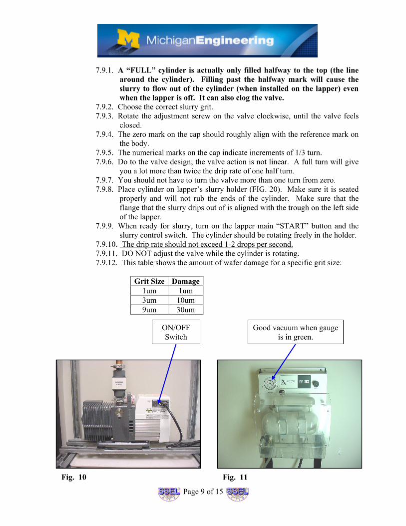
7.9.10. The drip rate should not exceed 1-2 drops per second. 7.9.11. DO NOT adjust the valve while the cylinder is rotating. 7.9.12. This table shows the amount of wafer damage for a specific grit size:
Grit Size Damage
1um 1um 3um 10um 9um 30um
ON/OFF Switch
Good vacuum when gauge is in green.
Fig. 10 Fig. 11
Page 10 of 15
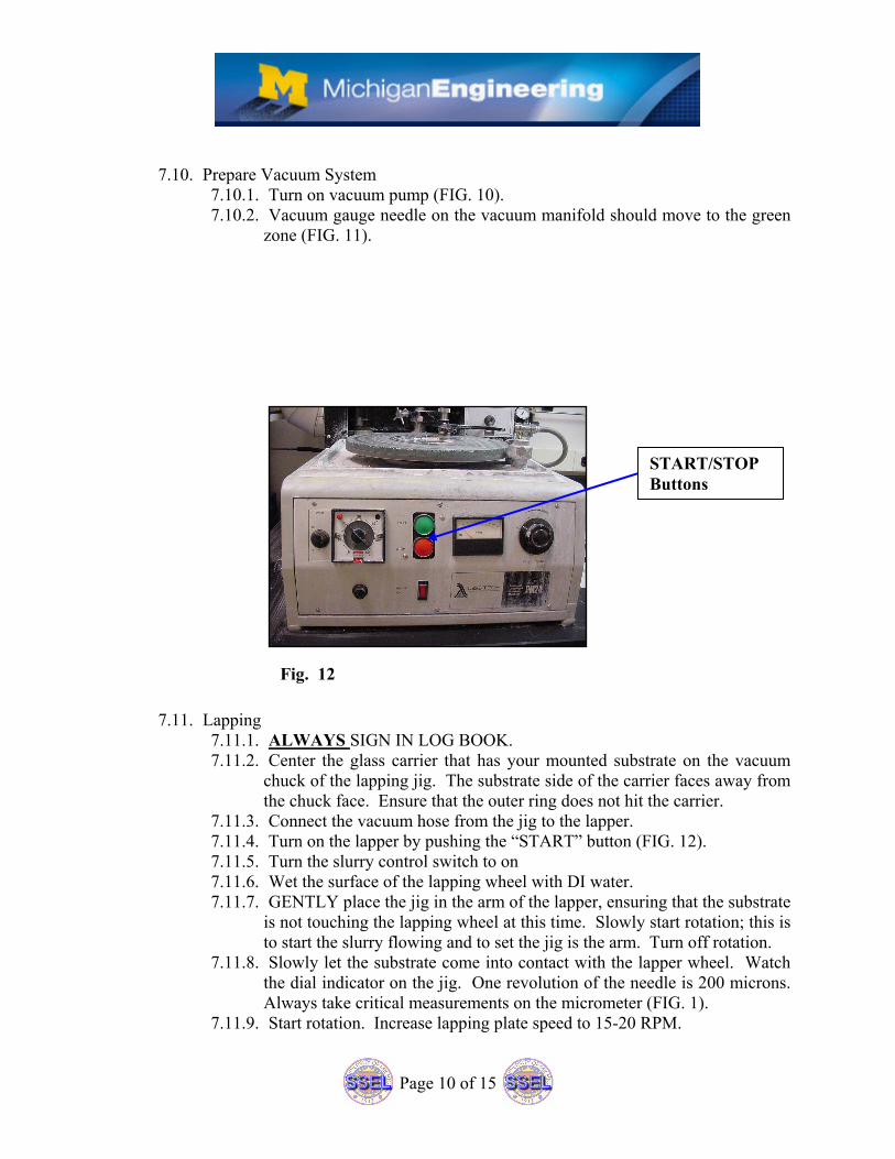
7.10. Prepare Vacuum System
7.10.1. Turn on vacuum pump (FIG. 10). 7.10.2. Vacuum gauge needle on the vacuum manifold should move to the green
zone (FIG. 11).
7.11. Lapping
7.11.1. ALWAYS SIGN IN LOG BOOK. 7.11.2. Center the glass carrier that has your mounted substrate on the vacuum
chuck of the lapping jig. The substrate side of the carrier faces away from the chuck face. Ensure that the outer ring does not hit the carrier.
7.11.3. Connect the vacuum hose from the jig to the lapper. 7.11.4. Turn on the lapper by pushing the “START” button (FIG. 12). 7.11.5. Turn the slurry control switch to on 7.11.6. Wet the surface of the lapping wheel with DI water. 7.11.7. GENTLY place the jig in the arm of the lapper, ensuring that the substrate
is not touching the lapping wheel at this time. Slowly start rotation; this is to start the slurry flowing and to set the jig is the arm. Turn off rotation.
7.11.8. Slowly let the substrate come into contact with the lapper wheel. Watch the dial indicator on the jig. One revolution of the needle is 200 microns. Always take critical measurements on the micrometer (FIG. 1).
7.11.9. Start rotation. Increase lapping plate speed to 15-20 RPM.
START/STOP Buttons
Fig. 12
Page 11 of 15
7.11.10. Add weights to the top of the jig to help speed the lapping process (if necessary).
7.11.11. Close the lid of the lapper to contain any generated fumes or slurry dust. 7.11.12. Measure the substrate thickness on the micrometer (FIG. 1) periodically
if your final thickness has to be precise. 7.11.13. Turn off slurry and system when correct thickness has been reached. 7.11.14. Remove jig and place in stand. 7.11.15. Disconnect vacuum line from jig at the top of the lapper. 7.11.16. Remove the glass carrier, rinse with DI water and dry. 7.11.17. Measure your sample on the micrometer to see if more lapping is
needed. 7.11.18. If you have lapped to the proper thickness, clean up the lapper, jig,
countertop, etc. 7.12. Clean Up
7.12.1. Clean up the equipment and area after every use. Trace amounts of Arsenic have been found on surfaces in the lapping room.
7.12.2. Ensure you are wearing gloves for the clean up. 7.12.3. Wipe down the lapping plate and jig using DI water, Kim wipes, and
swabs. 7.12.4. Also wipe down surrounding countertops and other surfaces.
7.12.4.1. Wipe down Slurry bucket lid. 7.12.4.2. Wipe down the blue cabinet next to the Lapper. 7.12.4.3. Place wipes in the slurry waste trashcan.
7.12.5. Solid waste such as used wipes, swabs, etc. should be bagged and placed in trashcan marked “Slurry Waste” by lapper. When trashcan is full, remove contents, double bag, label bag with “Slurry Waste”, and place in Chem. Room.
7.12.6. Check slurry waste bucket. If ¾ or more full, notify staff member (David Kouba) for disposal.
7.12.7. Ensure that there is NO abrasive powder residue left in the sink, countertops, lapping wheel, or other surfaces.
7.12.8. Mop the floor using the Swiffer mop and Swiffer wet wipes. 7.12.8.1. Place wipes in the solid Slurry waste trash.
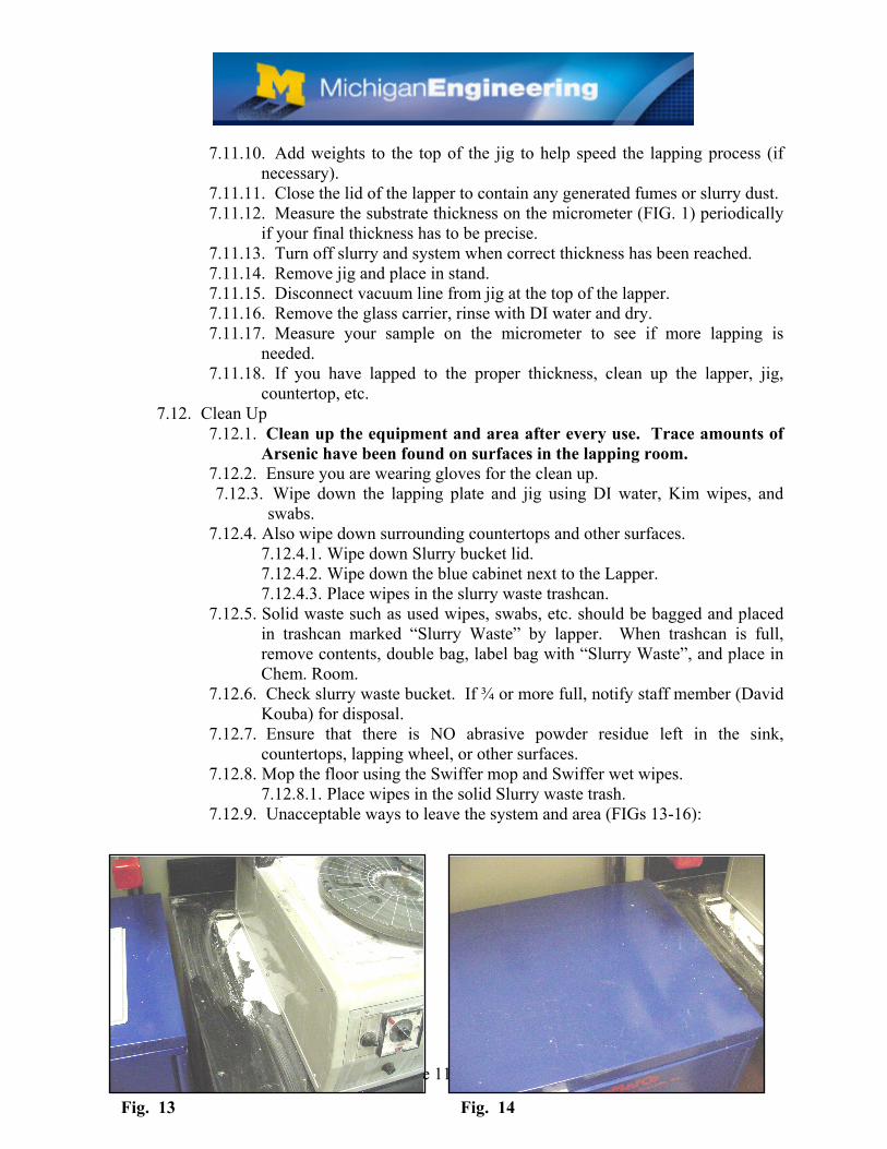
7.12.9. Unacceptable ways to leave the system and area (FIGs 13-16):
Fig. 13 Fig. 14
Page 12 of 15
7.13. Unmount Sample
7.13.1. CAUTION: Your thinned substrate is more fragile than before. Samples under 200um are much more fragile.
7.13.2. Set the hot plate to appropriate temperature to melt wax (Section 7.4). 7.13.3. Once the wax has been heated, gently push the samples off the block with
the butt end of a Teflon tweezers. You can also push/pull the substrate off the glass block by using the edge of folded filter paper or clean room paper, if your substrate is particularly fragile. 7.13.3.1. Add a path of wax to help slide the substrate off the carrier. 7.13.3.2. Do not “pop” the sample off the carrier. 7.13.3.3. Do not let tweezers slip; you might scratch your substrate.
7.13.4. Place substrates in the appropriate solvent(s) for a few minutes to dissolve wax and photo resist. The solvent(s) may be heated to speed up the process. Rinse off solvent with appropriate solution and dry with N2. CAUTION: You can break your substrate with the N2 if it is very thin.
7.13.5. Carefully remove glass carrier from hotplate and place on something metal to cool. You can crack the glass carrier if you cool it to quickly (wiping it with liquids). Set hotplate to default temperature.
7.13.6. Once the glass carrier has cooled, wipe with solvent to remove remaining wax.
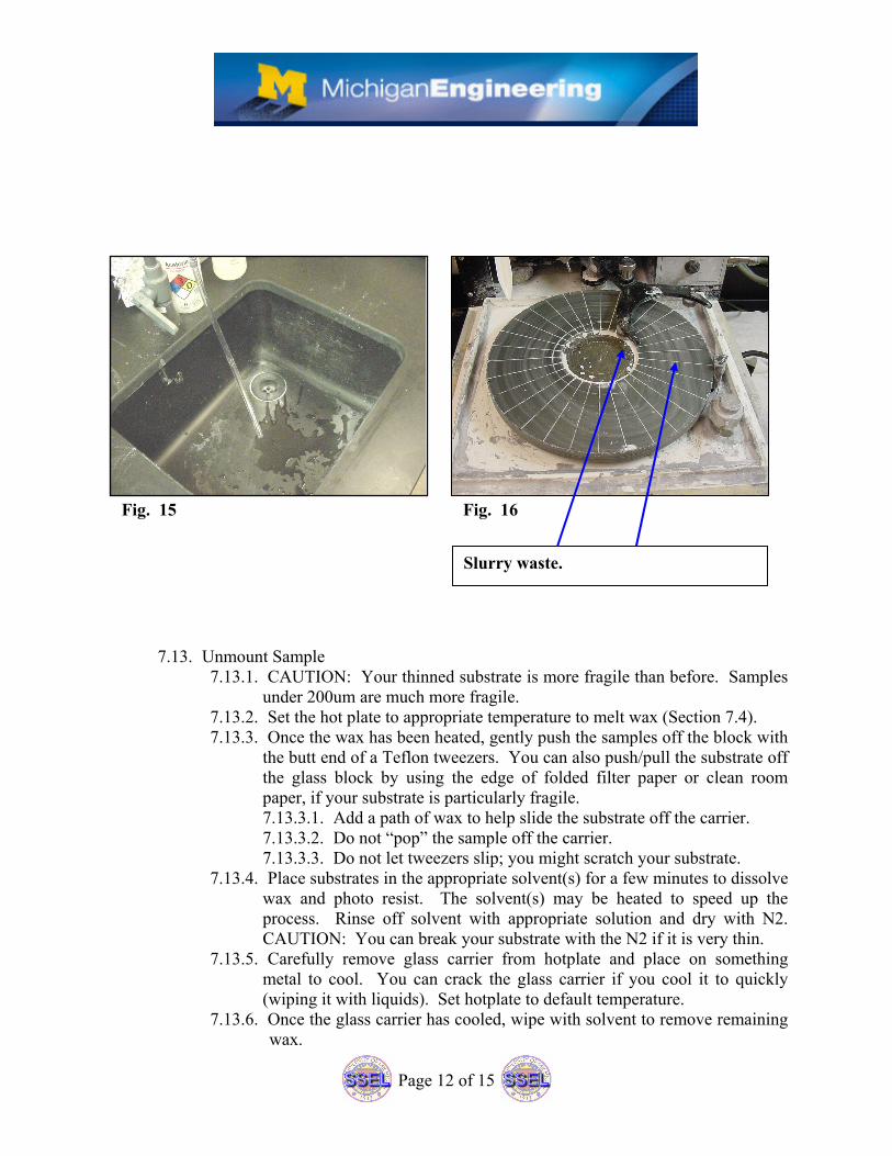
Fig. 15 Fig. 16
Slurry waste.
Page 13 of 15
7.13.7. Inspect substrate for photo resist (if used). 7.13.8. If photo resist residue exists, place substrate in hot PRS-2000 (if
compatible with substrate) for 10 minutes. DI rinse for five minutes and dry with N2.
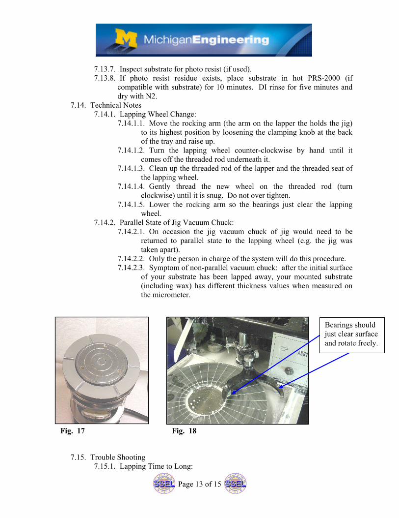
7.14. Technical Notes 7.14.1. Lapping Wheel Change:
7.14.1.1. Move the rocking arm (the arm on the lapper the holds the jig) to its highest position by loosening the clamping knob at the back of the tray and raise up.
7.14.1.2. Turn the lapping wheel counter-clockwise by hand until it comes off the threaded rod underneath it.
7.14.1.3. Clean up the threaded rod of the lapper and the threaded seat of the lapping wheel.
7.14.1.4. Gently thread the new wheel on the threaded rod (turn clockwise) until it is snug. Do not over tighten.
7.14.1.5. Lower the rocking arm so the bearings just clear the lapping wheel.
7.14.2. Parallel State of Jig Vacuum Chuck: 7.14.2.1. On occasion the jig vacuum chuck of jig would need to be
returned to parallel state to the lapping wheel (e.g. the jig was taken apart).
7.14.2.2. Only the person in charge of the system will do this procedure. 7.14.2.3. Symptom of non-parallel vacuum chuck: after the initial surface
of your substrate has been lapped away, your mounted substrate (including wax) has different thickness values when measured on the micrometer.
7.15. Trouble Shooting 7.15.1. Lapping Time to Long:
Fig. 17 Fig. 18
Bearings should just clear surface and rotate freely.
Page 14 of 15
7.15.1.1. Use coarser abrasive grit slurry. 7.15.1.2. Insufficient pressure on sample, adjust load adjustment screw on
jig and/or add weights. 7.15.2. Erratic Movement of Jig Within Roller Arm:
7.15.2.1. Roller arm bearings filled with slurry; clean with wipe and DI water.
7.15.2.2. Worn or damaged roller arm bearings. Call for help. 7.15.3. Glass Carrier Does Not Adhere to Jig Vacuum Chuck Even Though
Vacuum Manifold Gauge is in the Green. 7.15.3.1. Vacuum lines and quick connects from lapper to jig may be
clogged with slurry. 7.15.3.2. Back face of glass carrier may be dirty, chipped, or scratched. 7.15.3.3. Jig vacuum chuck face may be dirty or scratched. Call for help
if scratched. 7.15.4. Vacuum Leakage:
7.15.4.1. Wear or damage to components of the rotary vacuum adaptor. 7.15.5. Abrasive Feed Cylinder Not Turning:
7.15.5.1. Turn on cylinder rotation switch. 7.15.5.2. Cylinder not sitting properly in rotation mechanism. Reposition
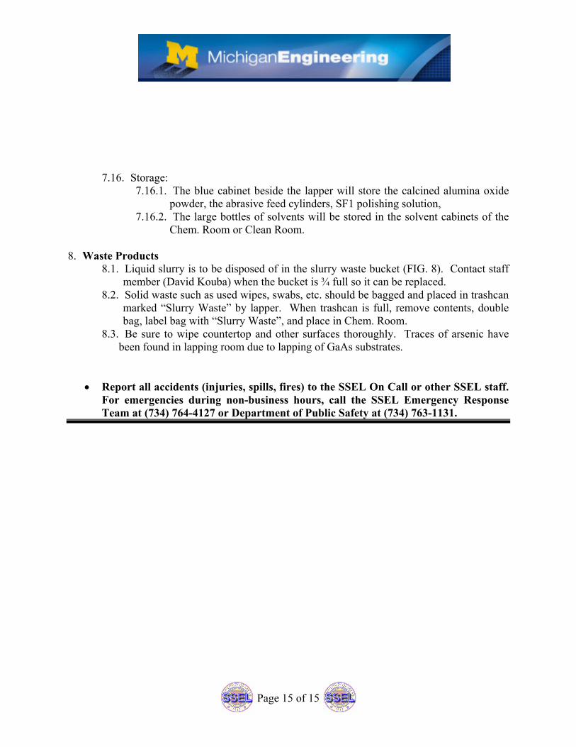
Cylinder. 7.15.5.3. Helix coupler came apart, reconnect (FIG. 20).
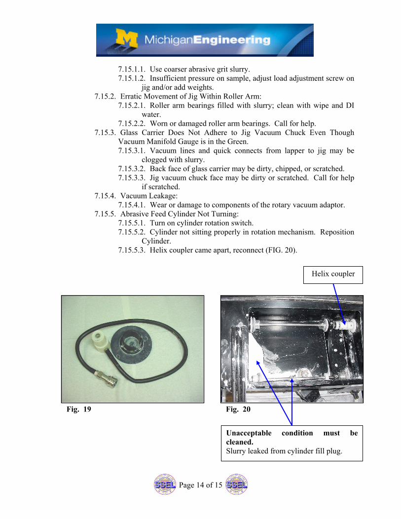
Fig. 19 Fig. 20
Helix coupler
Unacceptable condition must be cleaned. Slurry leaked from cylinder fill plug.
Page 15 of 15
7.16. Storage: 7.16.1. The blue cabinet beside the lapper will store the calcined alumina oxide
powder, the abrasive feed cylinders, SF1 polishing solution, 7.16.2. The large bottles of solvents will be stored in the solvent cabinets of the
Chem. Room or Clean Room. 8. Waste Products
8.1. Liquid slurry is to be disposed of in the slurry waste bucket (FIG. 8). Contact staff member (David Kouba) when the bucket is ¾ full so it can be replaced.
8.2. Solid waste such as used wipes, swabs, etc. should be bagged and placed in trashcan marked “Slurry Waste” by lapper. When trashcan is full, remove contents, double bag, label bag with “Slurry Waste”, and place in Chem. Room.
8.3. Be sure to wipe countertop and other surfaces thoroughly. Traces of arsenic have been found in lapping room due to lapping of GaAs substrates.
• Report all accidents (injuries, spills, fires) to the SSEL On Call or other SSEL staff. For emergencies during non-business hours, call the SSEL Emergency Response Team at (734) 764-4127 or Department of Public Safety at (734) 763-1131.