Embed Size (px)
Citation preview

Sony’s IP Live Production Technology / Technical White Paper
1
IP Live Production System
Technical White Paper September, 2017

Sony’s IP Live Production Technology / Technical White Paper
2
TABLE OF CONTENTS
TABLE OF CONTENTS ...................................................................................................................................... 2 1. INTRODUCTION ....................................................................................................................................... 3
1.1. WHAT IS SONY’S IP LIVE PRODUCTION SYSTEM ..................................................................................... 3 1.2. SONY’S IP LIVE TECHNOLOGY ................................................................................................................ 3 1.3. PURPOSE OF THIS DOCUMENT ................................................................................................................ 3 1.4. VERSIONS NOTICE ................................................................................................................................. 3 1.5. KEY TERMINOLOGY, ACRONYMS, AND ABBREVIATIONS.............................................................................. 4
2. BENEFITS OF SONY’S IP LIVE PRODUCTION SYSTEM ...................................................................... 5 2.1. BENEFITS THROUGH IMPROVED ROI ....................................................................................................... 5 2.2. BENEFITS THROUGH FUTURE-PROOFING ................................................................................................. 5 2.3. BENEFITS THROUGH IP TECHNOLOGY ..................................................................................................... 5
3. FUTURE APPLICATIONS FOR LIVE PRODUCTION ............................................................................. 6 3.1. AGNOSTIC PROGRAM PRODUCTION ......................................................................................................... 6 3.2. RESOURCE VIRTUALIZATION OVER THE NETWORK .................................................................................... 6 3.3. LIVE PRODUCTION AND FILE-BASED WORKFLOW INTEGRATION .................................................................. 6
4. SONY’S IP LIVE ENVIRONMENT OVERVIEW ........................................................................................ 7 4.1. IP LIVE SYSTEM MANAGER (LSM) SOFTWARE ......................................................................................... 7 4.2. IP LIVE SUPPORTED PRODUCTS .............................................................................................................. 7 4.3. IP SWITCH FABRIC WITH COTS HARDWARE ............................................................................................. 8
5. SONY’S IP LIVE TECHNOLOGY ............................................................................................................. 9 5.1. IP-BASED A/V ROUTING ......................................................................................................................... 9
5.1.1 Clean video switching over IP .......................................................................................................... 9 5.1.2 Broadcast-quality A/V transmission over IP ................................................................................... 13 5.1.3 Good timing reference & synchronization over Sony’s Networked Media Interface ...................... 14
5.2. DEVICE MANAGEMENT .......................................................................................................................... 19 5.2.1 Plug & play ..................................................................................................................................... 19 5.2.2 Device control ................................................................................................................................ 20 5.2.3 Device configuration ....................................................................................................................... 20 5.2.4 NS-BUS .......................................................................................................................................... 20
5.3. NETWORK DESIGN ............................................................................................................................... 21 5.3.1 Network routing and multicasting ................................................................................................... 21 5.3.2 Network topology ........................................................................................................................... 22 5.3.3 Quality of Service (QoS) ................................................................................................................ 22 5.3.4 Network virtualization technology .................................................................................................. 23 5.3.5 Software-Defined Network (SDN) .................................................................................................. 23
5.4. INTEROPERABILITY ............................................................................................................................... 24 5.5. REDUNDANCY ...................................................................................................................................... 25
5.5.1 Application redundancy .................................................................................................................. 25 5.5.2 A/V transmission redundancy ........................................................................................................ 26 5.5.3 Synchronization redundancy .......................................................................................................... 27
5.6. SECURITY ............................................................................................................................................ 27 5.7. MONITORING / MAINTENANCE ............................................................................................................... 30
5.7.1 Remote maintenance ..................................................................................................................... 31 6. CONCLUSION ......................................................................................................................................... 32 7. REFERENCES ........................................................................................................................................ 33

Sony’s IP Live Production Technology / Technical White Paper
3
1. INTRODUCTION IP technology has become ubiquitous within broadcast post-production environments. Most major broadcasters and post-production facilities are investing extensively not only in IP and network hardware but also in the skills required to set up and maintain such systems.
1.1. What is Sony’s IP Live Production System Now Sony can provide live production scenarios with more system design flexibility and control, greater efficiencies, and the potential for lower system costs. Sony’s IP Live Production System and its overarching IP Live technology not only replace conventional SDI-based environments (exceeding the performance of legacy systems) but also offer efficiencies in cabling and system architecture granularity. With IP Live from Sony, you also gain new features, capabilities, and workflows beyond the possibilities of traditional SDI-based legacy systems.
Moreover, Sony’s IP Live Production System provides a welcome level of future-proofing, meeting ever-increasing demand for more channels, more live programming, and ever-changing audience lifestyles. It can easily cater for emerging formats, technologies, and trends in A/V media such as 4K, high frame rate (HFR), 8K, and high dynamic range (HDR) video, as well as new extended gamuts and color spaces.
Sony’s IP Live Production System provides all this while still using common off-the-shelf (COTS) network hardware for supreme system architecture flexibility, along with the ultimate in migration and upgrade flexibility.
Sony’s IP Live approach enables industry-wide interoperability, and this has been and will continue to be driven by us. We work closely with other organizations to ensure the standardization of IP technologies, participating in many different alliances and interop activities. To enhanced the interoperability of IP Live production, our cameras, switchers, production servers and SDI-IP gateway will be compliant with the open standard format SMPTE ST 2110*.
*As of September 2017, SMPTE ST 2110 is a draft, pending/under development as the SMPTE standard.
1.2. Sony’s IP Live technology The technology used in Sony’s IP Live Production System, described in this white paper, extends the technology used in our first-generation A/V-over-IP interface, the NXL-IP55. However Sony’s IP Live Production System offers much more sophisticated signal processing, enabling a wider range of applications, video formats, and production environments – this system can be used for cutting-edge IP-based A/V routing scenarios.
The new network-related capabilities within Sony’s IP Live Production System include synchronization, network management, and security; while new capabilities related to audio and video processing include SDI-IP mapping, a low-delay video codec, overall low end-to-end system latency, and clean video switching. These are based on existing and draft standards complemented by a number of dedicated technologies.
1.3. Purpose of this document The purpose of this document is to describe Sony’s IP Live Production System, IP Live System Manager (LSM) software, the technology behind Sony’s Networked Media Interface, and our commitment to open standards including SMPTE ST 2110 and AMWA NMOS (Advanced Media Workflow Association Networked Media Open Specifications).
This white paper explains the benefits of Sony’s IP Live technology in section 2. Future applications for live production are explained in section 3, Sony’s IP Live Production System is reviewed in section 4, and the overarching IP Live technology is described in section 5.
1.4. Versions notice All content including the system overview, technology description, and all graphics are based on the development of Sony’s IP Live Production System as of September 2017. Sony’s IP Live solutions are subject to future improvement and enhancement without notice.
Contact your Sony representative for the latest on Sony’s IP Live Production System, and to confirm the latest version of this white paper.

Sony’s IP Live Production Technology / Technical White Paper
4
1.5. Key terminology, acronyms, and abbreviations Certain key terms within this document are shortened to acronyms or abbreviations for brevity and improved reading.
10GbE : 10Gbps Ethernet. 3G-SDI : 3Gbps SDI. 4K : A video format based on about 4,000 horizontal pixels, having about 4x the resolution of HD 8K : A video format based on about 8,000 horizontal pixels, having about 4x the resolution of 4K AMWA : Advanced Media Workflow Association A/V : Audio/Video BNC : Bayonet Neill-Concelman connector CER : Central Equipment Room COTS : Common Off-The-Shelf / Commercial Off-The-Shelf DHCP : Dynamic Host Control Protocol DiffServ : Differentiated Services. FEC : Forward Error Correction FPGA : Field-Programmable Gate Array GB : Gigabit (1,000,000,000 bits) Gbps : Gigabits per second GPIO : General-Purpose Input Output GPS : Global Positioning System HA : High Availability HD : High Definition HDR : High Dynamic Range HD-SDI : High-Definition SDI. HFR : High Frame Rate IEEE : Institute of Electrical & Electronic Engineers IGMP : Internet Group Management Protocol IP : Internet Protocol IT : Information Technology LLDP : Link Layer Device Protocol LLVC : Low Latency Video Codec LSI : Large-Scale Integration LSM : IP Live System Manager software MADI : Multi-channel Audio Digital Interface NDCP : Networked Device Control Protocol NMOS : Networked Media Open Specifications PIM-DM : Protocol-Independent Multicast –Dense Multicast PIM-SM : Protocol-Independent Multicast –Sparse Mode PIM-SSM : Protocol-Independent Multicast –Source-Specific Multicast PTP : Precision Time Protocol. QoS : Quality of Service. ROI : Return On Investment SD : Standard Definition SDI : Serial Digital Interface. SDN : Software-Defined Network SIP : Session Initiation Protocol SNMP : Simple Network Management Protocol SMPTE : Society of Motion Picture & Television Engineers SoC : System on a Chip SysLog : System Logging; a message logging system TLS : Transport Layer Security UI : User Interface UMD : Under-Monitor Display VLAN : Virtual Local Area Network WAN : Wide Area Network

Sony’s IP Live Production Technology / Technical White Paper
5
2. Benefits of Sony’s IP Live Production System Sony’s IP Live Production System can be seen simply as a replacement of conventional SDI systems, exactly emulating the performance characteristics of SDI with an IP solution. As such, this system would not really provide a convincing alternative to the A/V community. However, Sony’s IP Live Production System does not just match but actually exceeds the performance characteristics of SDI with a series of practical improvements and enhancements that make it a viable and even necessary replacement of SDI.
Sony’s IP Live Production System provides benefits in three broad areas outlined in the associated publication, “IP Live Production The Business of Broadcast”. These are:
• Improved ROI with a unified infrastructure for both file-based IT systems and IP-based live systems • Extensible and flexible future-proof system architecture that can support future video formats and other
emerging technologies, thus reducing investment risks • Maximized benefits of IP technology and infrastructure, with reduced overall production costs
2.1. Benefits through improved ROI IP Live from Sony provides a fully IP-capable live production environment that handles not only video but also audio and metadata. It also handles sub-microsecond system-wide synchronization and control. Once a live production system migrates fully to Sony’s IP Live environment, it can share resources with other IP-based production systems – this single infrastructure unifies and harmonizes file-based IT systems and IP-based live production systems. As well as protecting current dual-investment scenarios, this delivers greatly improved system ROI.
2.2. Benefits through future-proofing IP Live from Sony provides an extensible and flexible solution for the A/V media community which supports the evolution of workflows and working practices, as well as future video formats. It is estimated that the next decade will see the introduction, penetration, and general adoption of such technologies as 4K, HFR, 8K, and HDR video. Networked environments exchanging and transferring massive amounts of video data are becoming reality, placing increasing strain on network infrastructures. Sony’s IP Live ecosystem is designed from the start to support these new technologies, formats, working practices, and workflows.
2.3. Benefits through IP technology One of the biggest benefits of using IP is that it removes most of the limitations in device allocation once all the devices are connected to the network. In future, virtualized broadcasting systems will become reality. These systems are able to reach out and control every function and feature of every device on the network. All A/V media equipment will be stored in a central equipment room (CER) with remote user interfaces elsewhere in the production environment. Anyone who is authorized will be able to access any resource over the network at any time from any compliant interface. Maintenance will be easier with remote monitoring, configuration, and updating as batch operations over the network. This will provide maximum system operational efficiency.
Figure 1: From a conventional SDI system to an IP-based production system

Sony’s IP Live Production Technology / Technical White Paper
6
3. FUTURE APPLICATIONS FOR LIVE PRODUCTION Sony’s IP Live approach provides increasing opportunities for added-value content creation and improves the operational efficiency of the production system. Shifting from conventional SDI-based systems to IP-based transmission systems and connecting all equipment to a common network serves to maximize the benefits of IP. This provides central control over the entire production system.
But what does this mean for the future? What further applications can be envisaged in Sony’s IP Live ecosystem?
3.1. Agnostic program production With IP Live, Sony will ensure future support for different video formats, frame rates, and resolutions. Users will be able to build programs without worrying about the exact nature of the material. This agnostic approach will allow material from normal frame rate and dynamic range to coexist in the same system and same program as HDR and HFR material.
3.2. Resource virtualization over the network Virtualization allows the whole broadcast environment to be scaled to cater for changes in demand and workload. Broadcast companies can increase resources during certain events, like elections or important sports events. Broadcasters can select the functionality from a device as they need it. If a particular event requires a greater feature set from a particular resource, this can be provided during the event and reallocated when the event is over. The router size can be increased and the production switcher can be scaled allowing more resources to be allocated during larger events.
Virtualization also allows more than one studio to share resources. With Sony’s IP Live, centralized resources can be allocated to particular studios on an as-needed basis. This allows for very efficient resource allocation and sharing between studios during the production schedule.
3.3. Live production and file-based workflow integration An important concept of Sony’s IP Live approach is to integrate existing file-based production environments with live production systems. This concept has many obvious financial and operational efficiencies. All signals, including video, audio, metadata and control, not forgetting timing reference signals, are conveyed over IP. Resources can be shared between production systems, allowing file-based systems and live systems to be integrated into one. Broadcast stations will no longer need to invest twice in two different systems.
Figure 2: An example of future applications
Sony’s approach to IP Live provides the basic environment and technology that allows broadcasters to realize new program production possibilities, with new working practices. As Sony’s IP Live ecosystem grows, so do the future possibilities with new innovative program production methods.

Sony’s IP Live Production Technology / Technical White Paper
7
4. SONY’s IP LIVE ENVIRONMENT OVERVIEW A typical IP Live environment from Sony consists of the following elements:
• Sony’s IP Live System Manager (LSM) software application • Sony’s Networked Media Interface and/or SMPTE ST 2110-compliant devices
A variety of audio and video equipment with the Networked Media Interface or SMPTE ST 2110 connectivity
SDI-IP converters for legacy SDI-based equipment
• IP switch fabric with COTS hardware
Figure 3: Overall view of a typical IP Live Production System from Sony
4.1. IP Live System Manager (LSM) software Sony’s IP Live System Manager (LSM) software application forms the central control point for the entire production system, and offers a range of features not found in legacy SDI infrastructures.
These features include:
• An IP-based A/V routing application: this software aggregates device configuration and generates a virtual A/V router which can be controlled by users on the system
• A configuration management tool for all devices connected to the system: use this to quickly reconfigure the production system for different production scenarios or for customized configuration of individual devices
• A network management tool: this ensures IP video transmission with broadcasting quality, using QoS technology
• A fully-featured application which includes interoperability, security, redundancy, and maintenance functionality
4.2. IP Live supported products
Products that can fit directly into Sony’s IP Live Production System have integrated Networked Media Interface connectivity or will integrate SMPTE ST 2110 interface. This takes the form of dual RJ45, SFP+, QSFP+, SFP28 or QSFP28 connectors and provides direct connection into Sony’s IP Live network, either

Sony’s IP Live Production Technology / Technical White Paper
8
as a simple single connection or as a dual connection with a hitless failover capability.
Sony also provides SDI-IP converters to allow its IP Live ecosystem to integrate with existing legacy SDI A/V infrastructures. These were the first IP Live products from Sony to be introduced with fully compliant Networked Media Interface connectivity and 4K capability. These converters packetize SDI signals and provide a smooth transition for broadcasters from SDI live production to Sony’s IP Live Production System, allowing continued use of existing Sony and third-party equipment through any transition period. With wider use of its IP Live technology, Sony has now also released an end-to-end IP Live production solution with Networked Media Interface connectivity integrated into the design of devices such as cameras, switchers, production servers and SDI-IP gateway.
Figure 4: Products equipped with Sony’s Networked Media Interface
To enhance the interoperability of IP Live production, Sony’s cameras, switchers, production servers and SDI-IP gateway will continue to be compliant with the open standard format SMPTE ST 2110. And to expand the Networked Media Interface with SMPTE ST 2110, Sony will develop a bridge solution from previous formats.
4.3. IP switch fabric with COTS hardware A basic principle of Sony’s IP Live architecture is that systems can be built with common off-the-shelf (COTS) IP switches that support layer 2/3 switching. Sony’s IP Live approach tolerates and incorporates many kinds of hardware. While it may be unwise to integrate a hub or switch designed in the 1990s, most contemporary network hardware can be connected into the system successfully.
Furthermore Sony’s IP Live technology does not insist on the specialized versions of various network switch and router hardware. For instance, the latest flow-control-capable SDN IP switches and IEEE1588-supported IP switches are considered expensive at present, with a limited selection available on the market. The Networked Media Interface does not impose any specific requirements in this regard and will operate perfectly well with lesser switches and routers.

Sony’s IP Live Production Technology / Technical White Paper
9
5. SONY’S IP LIVE TECHNOLOGY This chapter explains the technology overarching Sony’s IP Live Production System, IP Live System Manager (LSM) software and the associated IP switch fabric.
IP Live technology from Sony combines several separate and well-established technologies as well as new cutting-edge technologies. Each technology element is selected to meet one or more of the following basic requirements of Sony’s IP Live Production System:
• Interoperability: The ability to operate seamlessly with other vendors’ products • Scalability: The ability to operate in current and future systems of any size • Efficiency: The ability for customers and users to realize a good ROI • Future-proofing: The ability to take advantage of new technologies and evolving trends
With IP Live, Sony seeks to utilize, wherever possible, standard technologies already in use in both the IT and A/V industries, and to realize three unique primary features:
• Reliable A/V transmission over IP • Format-agnostic A/V routing over IP • Clean video switching through IP
Other features and requirements follow on from these three primary features, as described in this white paper.
5.1. IP-based A/V routing A/V routing is a basic function of Sony’s IP Live Production System. Users can control routing functionality in the same way as with a legacy SDI-based routing system, through the IP Live System Manager. This provides a smooth transition from legacy systems to IP-based infrastructures without changing existing working practices or workflows, and still using third-party control applications.
Figure 5: A/V routing operation on Sony’s IP Live System Manager software application
Good IP-based A/V routing depends on three requirements: clean video switching (section 5.1.1), broadcast-quality A/V transmission (section 5.1.2), and good timing reference and synchronization (section 5.1.3).
5.1.1 Clean video switching over IP Good IP-based video switching, as realized by Sony’s IP Live Production System, is based on the following requirements:
• Clean video switching It is important to realize clean video switching in the A/V transmission over an IP network. There are three methods of achieving this: source-timed, switch-timed, and destination-timed video switching. There is a degree of timing uncertainty when using source-timed and switch-timed video switching. The most assured way of achieving clean video switching is with destination-timed video switching switches at the destination device. For this reason Sony has adopted destination-timed video

Sony’s IP Live Production Technology / Technical White Paper
10
switching in its IP Live environment.
• Optimizing the cost of network equipment As well as offering the most assured method of clean video switching, destination-timed switching also provides better overall network efficiency and reliability while optimizing costs:
o While other switching systems depend on specific IP switches, destination-timed video switching works with conventional off-the-shelf IP switches; neither specific IP switches nor limited network configurations are necessary
o Unlike other methods, destination-timed video switching does not require synchronous control; there’s no need for complicated setups such as video signal synchronization in the IP switch
o This retains a high degree of freedom and flexibility in system configuration
However, Sony has not ruled out the use of other approaches. If other methods present new advantages in terms of cost, implementation, or meeting specific customer needs, we are ready to extend our designs as necessary.
• Wider application range The ability of Sony’s IP Live Production System to support both clean and non-clean video switching allows this system to support a wide range of applications and scenarios from studios and outside broadcast facilities. For example, it supports production when clean video switching is important, and it supports non-real-time core systems (located in engine rooms and CERs) when non-clean video switching can be used.
• Unified control Sony’s IP Live System Manager maintains central routing functionality through destination-timed video switching by controlling the destination devices remotely. This software provides a control UI to users through a virtual A/V router.
5.1.1.1. Switching methodology comparison This section compares the technologies of the various different video switching methodologies.

Sony’s IP Live Production Technology / Technical White Paper
11
Non-clean video switching Clean video switching
Source-timed switching
Registers expected flow entry in the IP switch. (Requires a flow-control-capable SDN switch.) Controller changes the destination addresses for the stream in each source.
Updates the flow information of both source devices at exactly the same time.
Pros: The IP switch does not need to sync over the network. No double bandwidth penalty.
Cons: Complicated exception handling due to the requirement for synchronous processing of two source devices with respect to one destination device. Limited network topology since buffering is required in the IP switch, if there is a delay between source and destination devices.
Switch-timed switching
Switching video updates the flow table in the IP switch. (Requires a flow-control-capable SDN switch.)
The SDN controller switches the address of the stream to update the flow table during the vertical blanking period. Pros: No double bandwidth penalty Cons: The IP switch is required to find the vertical blanking period. Limited network topology since buffering is required in the IP switch, if there is a delay between the source and destination devices.
Destination-timed switching
Switching video commanded, generally using IP multicast, from destination device to conventional IP switch.
Temporarily receives a double stream at the destination device, finds the vertical blanking period, and then switches inside the destination device. Pros: No limitation for network topology. This can use COTS IP switches. Easy exception handling since one destination device can handle everything. Cons: Double bandwidth penalty.
Figure 6: IP video switching methodology comparison
Figure 7: Overview of video switching methodologies
5.1.1.2. Destination-timed switching This section explains the two main forms of destination-timed switching:
• Rough stream switching using IGMP (where two streams overlap) • Accurate stream switching using frame numbers embedded in the IP packet headers

Sony’s IP Live Production Technology / Technical White Paper
12
Figure 8: Destination-timed switching
The switching procedure is shown in figure 8 and operates as follows:
1. The IP stream transmitter puts video frame numbers into the network headers and sends the stream packets over the network
2. The IP Live System Manager issues a stream switch request
3. The IP stream receiver issues IGMP messages to join and leave the correspondent streams
4. The IP switch starts and stops the correspondent streams according to the IGMP message
5. With accurate stream switching, the IP stream receiver also removes unnecessary packets from the input streams according to the information from the IP Live System Manager, and outputs a clean switched stream

Sony’s IP Live Production Technology / Technical White Paper
13
5.1.2 Broadcast-quality A/V transmission over IP 5.1.2.1. Networked Media Interface
Sony’s Networked Media Interface is capable of supporting future-proofed IP-based A/V transmission. Frame boundary awareness also allows the Networked Media Interface to achieve clean video switching, which is required for live production. In addition to this, the IP packetizing approach of the Networked Media Interface distinguishes between video, audio, and metadata based on the header of each IP packet. This makes it easy to extract specific essence from the A/V stream. This improves workflow efficiency in scenarios where essence may need to be separated, combined, transmitted, or switched. The audio production system, for instance, could easily extract the audio essence from the combined A/V stream.
5.1.2.2. Packetizing for A/V transmission (essence-independent mapping) The first issue to be considered when converting an SDI-based environment to an IT-based environment is mapping the SDI payload information into an IP datagram payload.
Sony’s Networked Media Interface supports IP mapping of SDI signals in which video, audio, and metadata are placed in separate datagrams so that they can be dealt with independently. This mapping is very useful, for example, in situations where the video signal is compressed, as it saves network bandwidth as well as providing a method for processing audio, video, and metadata separately when required, something that is likely in A/V post-production environments.
This packetization of the Networked Media Interface has already been published as SMPTE RDD40.
5.1.2.3. Mechanisms to protect against transmission errors (forward error correction) With Sony’s IP Live technology, the bandwidth reservation method prevents packet loss caused by network congestion. Nevertheless, signal quality deterioration can occur, such as packet loss caused by electrostatic noise generated on an Ethernet cable. To avoid this, the data stream is encoded with additional data in the form of forward error correction (FEC). This can restore packet loss on the connection by using a special FEC-encoding method that takes into account the information contained within a single video frame. The FEC-encoded stream can be simultaneously protected and switched within video frame boundaries.
5.1.2.4. Support for compressed video during transmission across the network (LLVC) The required bit rates for broadcast video increase rapidly at higher video resolutions. For example, HD 1080i requires an HD-SDI connection with a bit rate of 1.485 Gbps, while for a 1080p signal, a 3G-SDI connection requires a bit rate of 2.97 Gbps. 4K video signals require data rates ranging from 6 Gbps to 12 Gbps or more. These very large data rates can easily exceed the data capacity of today’s commercially available 10GbE fiber optic transports. Hence, there is a need to use high-quality video compression with extremely low latency.
Sony has developed a suitable codec for the Networked Media Interface that minimizes encoding and decoding process latency to within several milliseconds, while providing visually lossless picture quality. Using this compression technology, the required network bandwidth can be reduced while maintaining the high levels of picture quality required in broadcast applications. For example, Sony’s Networked Media Interface can transmit up to four 1080i HD signals using a single gigabit Ethernet cable, or two 4K signals using a single 10-Gbps Ethernet cable.
Resolution bit-depth Frame Rate (Maximum) Compression Non-compression
720 x 480 10 59.94i - 720 x 576 10 50i - 1280 x 720 10 60p 1920 x 1080 10 60p 2048 x 1080 10 60p 3840 x 2160 10 60p - 4096 x 2160 10 60p -
Figure 9: Supported formats for YCbCr 4:2:2 video
The low latency video codec (LLVC) developed by Sony achieves both low latency and high image quality. This codec has already been published as SMPTE RDD34. LLVC uses line-based wavelet transform and

Sony’s IP Live Production Technology / Technical White Paper
14
line-based entropy coding technology. This type of wavelet transform is equivalent to full-screen wavelet transform, and is a very efficient way of processing high-resolution images with 4K resolution or more. LLVC achieves visually lossless compression by combining its unique highly efficient line-based entropy coding with fine rate control in the transmission unit. LLVC provides totally lossless compression for simpler video sequences.
5.1.2.5. Support for standardized format (SMPTE ST 2110) SMPTE ST 2110 is the A/V transmission format which is under standardization driven by SMPTE as of September 2017. In SMPTE ST 2110, video, audio, and auxiliary data are transmitted with separate multicast streams as shown in figure 10.
Figure 10: SMPTE ST 2110
As part of its IP Live solution, Sony will release camera, switcher, production server and SDI-IP gateway supporting SMPTE ST 2110.
5.1.3 Good timing reference & synchronization over Sony’s Networked Media Interface 5.1.3.1. Background
SDI infrastructures use digital syncs to lock equipment. Quite often syncs are derived from the input video, rather than a separate connection. This saves on cabling. Traditional broadcast syncs need to have sub-microsecond reference accuracy for proper timing between equipment.
This same accuracy is required with the introduction of Sony’s IP Live Production System. However, the concept of sub-microsecond reference accuracy does not fit well with the basic principles of IP networks yet. Various applications have encouraged the introduction and evolution of extremely fast and accurate timing protocols over IP. These allow two or more pieces of equipment to lock together with the kind of accuracy that is taken for granted in conventional A/V systems.
In particular the IEEE-1588 standard defines the so-called precision timing protocol (PTP) for locking two pieces of equipment over an IP network. SMPTE ST 2059 defines the use of PTP within the A/V media community for locking one piece of video equipment to another over IP.
Therefore all Sony’s IP Live-compliant equipment using the Networked Media Interface is fully SMPTE ST 2059-compliant. The Live System Manager can manage several logical groups of devices, each locked to a separate master clock. Each logical group is allocated a PTP domain number. Thus Sony’s IP Live Production System can be built with two or more different video formats co-existing in the same system, for instance both 50-Hz and 60-Hz-based systems.

Sony’s IP Live Production Technology / Technical White Paper
15
Figure 11: The network genlock group concept
5.1.3.2. IEEE 1588: Precision Time Protocol (PTP) IEEE 1588 PTP is one of a few time-synchronization protocols used over IP networks. Unlike other time-synchronization protocols, PTP is capable of synchronizing devices on the network with sub-nanosecond accuracy.
PTP achieves time synchronization by exchanging messages between a (grand) master and slaves across the network as described in figure 12. The followings are typical PTP messages:
• Sync • Delay_Req • Delay_Res
Firstly, a (grand) master sends a sync message to the slave. The time that the message is sent is defined as t1. The slave registers this time when the message is received as t2.
The slave then sends a Delay_Req message back to the (grand) master registering this time as t3. The (grand) master registers the time that the message is received as t4 and sends Delay_Res message with t4 to the slave. This message-exchange cycle is repeated periodically and the slave obtains a set of timestamps (t1, t2, t3, and t4 in each cycle) which it uses to synchronize its time with that of the (grand) master.

Sony’s IP Live Production Technology / Technical White Paper
16
Figure 12: PTP sequence
PTP boundary clock
As the design of PTP is based on the assumption that network delay is steady, some measures are required under highly loaded network conditions. PTP boundary clock is one of the countermeasure technologies defined as IEEE1588.
An IP switch with a PTP boundary clock function can reduce network load as the data residence time in this IP switch will not be counted. As a mechanism, the PTP master/slave function is assigned on each port of the IP switch. The PTP clock toward the end PTP slave device will be generated by a new PTP master port in the IP switch, which is synchronized with the PTP clock from the slave port within the IP switch that originally synchronized with PTP grand master, as shown in figure 13.
Figure 13: Mechanism of PTP boundary clock technology
In addition, the boundary clock function facilitates building a large system as it can make a hierarchy structure to reduce the load per PTP master, as shown in figure 14.

Sony’s IP Live Production Technology / Technical White Paper
17
Figure 14: PTP master-slave hierarchy
5.1.3.3. SMPTE ST 2059: the SMPTE profile of IEEE 1588 One of the most important technologies in the current workflow and operational practices of SDI-based systems is synchronization. All devices in the system are synchronized with each other using a common synchronization signal. This guarantees equal phasing for all output signals of the various devices in the system. SMPTE is developing a set of standards in Technology Committee 32NF for time and frequency synchronization over an IP network in a professional broadcast environment.
Sony’s IP Live Production System uses network synchronization technology from the SMPTE ST 2059 standard. SMPTE ST 2059-1 specifies the epoch of 1st Jan 1970 at exactly 00:00:00 (midnight) according to International Atomic Time. It also specifies A/V signal alignment to this epoch. SMPTE ST 2059-2 specifies the particular profile (packet rate, message extension, and more).
With its IP Live Production System, Sony focuses on the following two issues:
• Having sufficient synchronization accuracy using COTS IP switches One of the major reasons for adopting Sony’s IP Live Production System is its use of standard IT technologies. However, when seeking high-accuracy synchronization under high network loads, it is commonly considered essential to use specialized time-aware network devices such as transparent clock switches. Yet using COTS IP switches, synchronization implemented in the Networked Media Interface achieves a high level of accuracy under high network loads that is equal to the accuracy exhibited by legacy SDI-based synchronization systems.
• Enabling migration from current synchronization systems Figure 15 shows an idealized IEEE 1588-based synchronization system in which a global reference, such as GPS, is used as the time source. By sharing a reference time, synchronization can be achieved between PTP slaves that are not even necessarily connected to the same PTP (grand) master. While this could be the optimum solution for new facilities, it does not consider migration from a legacy synchronization system.

Sony’s IP Live Production Technology / Technical White Paper
18
Figure 15: Idealized use case of PTP for a green-field facility
Sony’s Networked Media Interface provides an option to use a legacy synchronization signal such as black & burst, HD-SDI, or tri-level mixed syncs as the master time source generator for the PTP system. This could be an optimum solution for an IP infrastructure when replacing part of an established SDI-based system, as illustrated in Figure 16.
Figure 16: Migration use case within a facility

Sony’s IP Live Production Technology / Technical White Paper
19
5.2. Device management Sony’s IP Live System Manager has the capability to control, configure, and manage all Sony and third-party Networked Media Interface-compliant devices on Sony’s IP Live network. New devices can be connected to Sony’s IP Live Production System easily with the plug & play feature of this software application and the Networked Media Interface.
5.2.1 Plug & play In the past, SDI-capable products have been widely accepted because of their intuitive use and easy handling. The IP Live System Manager software application provides the same user experience through a plug & play feature. This software feature automatically discovers any compliant and supported Networked Media Interface device and makes it ready for immediate use as soon as it is connected into Sony’s IP Live Production System.
Essentially Sony’s IP Live System Manager and the Networked Media Interface-compliant device exchange details about each other over the network. The device discovers the software application as a service over Sony’s IP Live network and, in turn, the IP Live System Manager discovers the device type and its capabilities on this network.
5.2.1.1. Plug & play process SDI has gained popularity in the past because of its intuitive simplicity and ease of use. Sony’s IP Live equipment has been developed with the same design philosophy by using a plug & play methodology to connect equipment to Sony’s IP Live Production System. As soon as a Networked Media Interface-compliant device is connected to the system, it is recognized by the IP Live System Manager, integrated into the network, and becomes ready for immediate use.
When a Networked Media Interface-compliant device is connected to Sony’s IP Live Production System, two exchanges take place between the new device and the IP Live System Manager:
• Service discovery by the Networked Media Interface-compliant device • Device discovery by the IP Live System Manager As shown in figure 17, when a Networked Media Interface-compliant device connects to Sony’s IP Live Production System using plug & play, the device first needs to discover the IP Live System Manager software application as a service.
Figure 17: Plug & play mechanism
The discovery procedure is illustrated in figure 17 and operates as follows:
1. The discovery process uses the dynamic host control protocol (DHCP) server option to distribute the IP Live System Manager IP address to the device
2. The device then connects to the IP Live System Manager, and this software application can discover and centrally manage the device
This is a similar model to that of a session initiation protocol (SIP) adopted in large-scale real-time communication systems such as IP telephony. Sony’s IP Live technology adopts SIP because of its efficient approach to managing a system containing many connected devices. SIP has two service discovery methods: using DHCP and DNS. Sony’s Networked Media Interface uses the DHCP discovery method (RFC 3361) to simplify Sony's IP Live architecture.

Sony’s IP Live Production Technology / Technical White Paper
20
5.2.2 Device control All Networked Media Interface-compliant devices are controlled and configured over the network. Sony’s new networked device control protocol (NDCP), designed specifically for live production, is used to control and configure Networked Media Interface-compliant devices. This protocol has the following characteristics:
• Fast message processing based on a binary format • Accurate real-time supported event notification • High availability supported control session redundancy Sony’s NDCP is open for use by third-party device developers and vendors in terms of protocol specification.
The IP Live System Manager supports AMWA NMOS (Advanced Media Workflow Association Networked Media Open Specifications), the standardization process for device management. This means that the software can control NMOS devices in the same way as it controls NDCP devices.
In addition, Sony IP Live System Manager (LSM) software can register the NDCP devices into NMOS RDS in order to publish the IP address or A/V stream data to other vendors’ management systems. Refer to section 5.4 for this interoperability function.
5.2.3 Device configuration Sony’s IP Live System Manager (LSM) software provides centralized management of devices over Sony’s IP Live network. Users can change many aspects of device configuration at any time.
This software manages configuration across a group of devices connected to Sony’s IP Live Production System. The workgroup feature can be used to instantly change many configuration settings across many devices, depending on the broadcast or production scenario. Each device has a specific configuration when associated with the workgroup.
For instance, an outside broadcast truck could use the workgroup feature of the IP Live System Manager to reconfigure Sony’s entire IP Live Production System within the truck for each venue the truck supports. Or a broadcast studio could use the workgroup feature to reconfigure Sony’s IP Live studio environment to meet different program needs during the week’s production schedule.
The workgroup feature can also be used to quickly configure devices offline in the event of device failure, so that failed devices can be quickly replaced in the system.
Figure 18: Sony’s IP Live workgroup concept
Workgroups are therefore a very powerful feature within Sony’s IP Live System Manager (LSM) software for managing production facilities in accordance with structured and repetitive production schedules, and coping with emergencies without program downtime.
5.2.4 NS-BUS NS-BUS is an IP-based management protocol defined in the system layer of Sony’s IP Live Production System. It is used to switch the cross-point from the hardware control panel or an external management system through the IP Live System Manager. Furthermore, NS-BUS supports name and tally transmission between the software application and the production switcher, and ensures external SDI router control from this application.

Sony’s IP Live Production Technology / Technical White Paper
21
NS-BUS specifications are open to third-party vendors to develop UI applications, external management systems, and devices to manage from/to Sony’s IP Live Production System.
Figure 19: The NS-BUS function
5.3. Network design Network design is a very important aspect of mission-critical operation in Sony’s IP Live production. With IP Live, Sony aims to unify with file-based content production systems and integrate within an existing network infrastructure.
The following criteria support Sony’s IP Live Production System network design:
• Ensure network designs can use COTS IP switches, increasing equipment choice and availability and reducing network equipment costs
• Realize a high-availability network with Sony’s IP Live • Ensure QoS capability based on DiffServ technology These items are not intended as a rigid definition. Network design may be changed and the overall architecture tuned and scaled by the user or system integrator. This maintains a strong sense of design flexibility and freedom. From a technical point of view, Sony will publish a network requirement document which includes the evaluation criteria for COTS IP switches, network configuration, and more. The essential principle of Sony’s IP Live approach is that overall network design is based on standard technology as much as possible so that users, network designers, system architects, and system integrators are not locked to any specific network vendor.
5.3.1 Network routing and multicasting With IP Live, Sony uses IP multicast technology. This allows content to be sent to multiple receivers in the same way as with a conventional SDI-based A/V router. IP multicast technology improves traffic efficiency for network infrastructures. It does not send unnecessary traffic because the IP switch copies each IP packet and sends copies to multiple destinations as required by the system. Sony’s IP Live approach only requires that the COTS IP switches support IP multicast technology.
• IGMPv3 This protocol manages multicast groups supporting the IGMP immediate-leave and host-tracking features.
• PIM-SSM This is required for multicast routing passing through a layer 3 network. PIM-SSM has less traffic than PIM-SM which requires a rendezvous point (RP) and PIM-DM in which flooding can occur.
• IGMP snooping

Sony’s IP Live Production Technology / Technical White Paper
22
This performs multicast packet flooding suppression in layer 2 networks.
5.3.2 Network topology It is recommended that core-edge network topology is used in Sony’s IP Live Production Systems, when using IP multicast (IGMPv3)-based A/V routing. Sony’s larger IP Live Production Systems can also be designed around the so-called core-aggregate-edge topology, with aggregate IP switches between the core and edge. Of course, small systems can also be designed as a core-only topology. All these topologies would work well with IGMPv3.
Figure 20: Core-edge topology
As shown in figure 20, it is assumed that a core IP switch running PIM-SSM and IGMPv3 is installed, and edge IP switches running IGMP snooping are installed and connected to the core IP switch.
The use of spine-leaf configurations is under review. Spine-leaf has gained a certain degree of popularity in data centers recently. Flow-control-based SDN technology is also under review. See section 5.3.5 for more information on flow-control-based SDN.
Two remote systems could be connected via a WAN. This is useful for physically separated systems such as remote production or resource-sharing scenarios.
Sony’s IP Live topologies can also be used for local network redundancy. In this case the two networks would be identical. Any device connected to this redundant arrangement would need to be SMPTE ST 2022-7-compliant, with a connection to both networks. Each device would perform hitless failover to the redundant network in the event of packet loss. This arrangement is ideal for live production with no time lag for failover.
5.3.3 Quality of Service (QoS) With IP Live, Sony adopts DiffServ, a particular QoS technology, to ensure the fast transfer of particular IP packets through Sony’s IP Live Production System. Packets are classified according to their priority. DiffServ has been chosen because of its wide acceptance in the IT community and widespread adoption in most COTS switches.
This DiffServ QoS technology is particularly useful for IP Live synchronization where PTP-timed IP packets are conveyed through the network with the highest priority, for lowest latency with no packet loss. This provides accurate sub-microsecond reference timing across Sony’s IP Live Production System.

Sony’s IP Live Production Technology / Technical White Paper
23
Figure 21: The DiffServ-based QoS model
Figure 21 shows input traffic at an edge switch as it is transferred through the switch and is remarked as it exits the switch. Every packet in Sony’s IP Live Production System is allocated a priority class, and is thus given priority to pass through the switch. Some packets have higher priority than others. PTP packets entering the switch will always be remarked with the highest classification as they exit the switch.
Good network design is important in properly allocating the available bandwidth across Sony’s IP Live Production System. With sufficient bandwidth allocated for PTP packets, A/V streams, and any control and maintenance data, Sony’s IP Live approach can provide a very flexible and controllable infrastructure for broadcast and production environments.
5.3.4 Network virtualization technology There are several kinds of network virtualization technology in use today. With IP Live, Sony adopts VLAN to improve traffic accommodation efficiency. In core-edge-based networks, the network is divided into multiple VLANs at the edge IP switch which, in turn, is connected to the core IP switch. This improves traffic accommodation efficiency.
Figure 22: Using VLAN to improve traffic accommodation efficiency
Other virtualization technologies have not been adopted at present, due to their lack of suitability in live production network design.
5.3.5 Software-Defined Network (SDN) SDN technology provides flexible network control that cannot be achieved with conventional IP switch control.
NETCONF has been chosen for use with Sony’s IP Live Production System as an SDN technology because almost all COTS IP switches support NETCONF. SDN networks divide IP switch functionality into a control plane and data plane. Sony’s IP Live Production System emulates this SDN technology, with the IP Live System Manager as the control plane, and NETCONF is used for configuring the IP switches dynamically.
As IP Live from Sony supports destination-timed switching, it does not currently support any other flow-control-capable SDN protocol, such as OpenFlow. Flow-control-capable SDN IP switches are

Sony’s IP Live Production Technology / Technical White Paper
24
considered too cutting-edge and expensive at present to support the underlying COTS principle of Sony’s IP Live design. Sony will continue to investigate the possibility of using flow-control-capable SDN protocols, technology and hardware in Sony’s IP Live Production System while still maintaining the basic COTS principles of Sony’s IP Live design.
5.4. Interoperability Sony’s IP Live approach provides a high level of interoperability. Broadcast stations and post-production facilities are generally multi-vendor environments. Interoperability is therefore an important concept for Sony, allowing IP Live to co-exist with other vendors’ systems and third-party products.
This is why Sony’s IP Live Production System offers various aspects of interoperability, including system integration, device control, A/V transmission, network timing, and synchronization.
• Interoperability for third-party vendor controller systems Sony’s IP Live Production System can integrate flexibly with third-party vendor A/V routing systems. We can provide a new external router control protocol to alliance vendors, providing interoperability with existing A/V router protocols. This protocol is able to accept A/V routing commands from third-party vendor systems, and can operate these systems using this protocol.
This new external router control protocol is not only intended for routing operations but can also be used for name integration, to display port names on an under-monitor display (UMD).
Legacy protocol interfaces such as RS422, RS232c, and GPIO can co-exist with Sony’s IP Live Production System in the same network infrastructure using VLAN technology for separated networks, if serial-over-IP is supported.
• Interoperability for A/V transmission Sony’s IP Live devices will be able to receive or transmit A/V signals over the IP network from/to third-party vendor devices which support SMPTE ST 2110. This is because Sony’s IP Live devices will be fully compliant with SMPTE ST 2110. As a result, Sony’s cameras, switches, and production servers will be able to connect with third-party vendor’s multi-viewers and with multiple other vendor devices to build an IP Live Production System.
• Interoperability for network timing and synchronization IP Live from Sony is fully compatible with SMPTE ST 2059 so that it can be built into a system using a third-party vendor PTP master that is compatible with SMPTE ST 2059.
• Interoperability for IP audio systems AUDINATE and Sony are alliance partners. Sony’s IP Live technology ensures compatibility with IP audio systems supported by DANTE, and by using MADI-capable devices which support DANTE, you can use existing MADI-supported devices. In addition, IP Live from Sony will be able to support AES67 for interoperability with future AES67-capable AUDINATE products.
• Interoperability for device control Sony’s IP Live technology supports AMWA NMOS (Advanced Media Workflow Association Networked Media Open Specifications), the standardized process for device management. Its development is driven by the Networked Media Incubator Project.
NMOS concentrates on ensuring plug & play interoperability between multiple vendor devices, including auto registration and discovery, start transmission suspension, switching orders, and more.

Sony’s IP Live Production Technology / Technical White Paper
25
Service Discovery Registration API Node API Connection Control API
Figure 23: AMWA NMOS
Sony’s IP Live Production System will support NMOS, enabling the multi-vendor workflow illustrated in figure 23.
5.5. Redundancy
With IP Live, Sony supports several aspects of redundancy to sustain live production operations without drop-out or failure. Each of these redundancy features is optionally selectable, depending on user requirements:
• Application redundancy • A/V transmission redundancy • Synchronization redundancy
These features are fully redundant configurations, so called active-active, so that Sony’s IP Live Production System can continue to operate without downtime if system failure occurs.
5.5.1 Application redundancy
Sony’s IP Live technology has an application-redundancy capability, ensuring high availability at the application layer. This is achieved by duplicating network configuration and server clustering.

Sony’s IP Live Production Technology / Technical White Paper
26
Figure 24: Application redundancy
Application redundancy is realized by a combination of the following approaches:
• Notification-based status synchronization (mainly used for video switching control) This returns the notification of control results to both IP Live System Manager servers simultaneously. This can be matched across both application control statuses from Sony’s IP Live device status contained in the notification.
• Application data synchronization (mainly used for device configuration) Synchronization between the two IP Live System Manager servers is event-driven. If the configuration is changed through one of the servers, this event triggers synchronization with the other server maintaining a continuous record of connected/disconnected devices on Sony’s IP Live Production System.
5.5.2 A/V transmission redundancy Sony’s IP Live Production System can transmit an A/V stream with redundancy for critical applications where drop-out or connection failure is unacceptable. This is achieved by duplicating the network configuration in accordance with SMPTE ST 2022-7.
Network redundancy technology, in common use across the IT community, is usually implemented by deploying at least two sets of IP switches. The first set of switches acts as the primary transmission path for data exchange between connected devices, while the second set acts as a backup to the primary switches.
In the event of a critical error or failure, network traffic is automatically transitioned from the primary set of switches to the backup set. However, there is a high likelihood of data loss or corruption during this transition time.
Figure 25: Example of basic IT network redundancy

Sony’s IP Live Production Technology / Technical White Paper
27
In the case of Sony’s IP Live Production System, the sender transmits duplicated media datagrams over two entirely separate network paths, and the receiver chooses datagrams from both the primary and secondary network paths. When one path is lost, a hitless failover occurs in compliance with SMPTE ST 2022-7, and there is no loss of data or disturbance in the A/V stream.
Figure 26: Hitless failover
5.5.3 Synchronization redundancy Sony’s IP Live technology can perform synchronization redundancy. There are two options: the first is network redundancy and the second is PTP master redundancy.
Figure 27: Synchronization redundancy
• Synchronization redundancy through network redundancy This is achieved in the same way as A/V transmission redundancy (explained in the previous section) by sending the same synchronization signal through two network paths. This unique feature provides hitless failover redundancy for synchronization reference signals while still complying with SMPTE ST 2059.
• Synchronization redundancy through PTP master redundancy Each PTP slave device can join two PTP domains, each locked to their own PTP master. Sony’s IP Live System Manager informs each device what the PTP domain numbers are. Once joined to the PTP domains, each device can use hitless failover to switch from one PTP master to the other, in the event of a failure.
5.6. Security IP technology offers the kind of remote control, configuration, and maintenance not possible with legacy SDI-based systems. However, this freedom also introduces several possibilities both for malicious attacks and inadvertent user operation.
Imagine, for instance, if someone manages to hack into an IP Live system from a remote location and illegally tap into an important live broadcast. Imagine also if a regular user changes the format or frame rate of a device by mistake, while it is being used for a live production sports event.

Sony’s IP Live Production Technology / Technical White Paper
28
Because of these and similar scenarios, Sony’s IP Live Production System has been designed to protect the whole control path using the TLS protocol. In addition, this system uses a selection of proven and well-established network technologies to maintain system security.
There are two possible security risks in general for Sony’s IP Live Production System:
• Taking over the system by spoofing a user and/or a single device • Unexpected traffic flow leading to denial of service
To prevent these situations, Sony’s IP Live Production System offers user authentication and device authentication features.
• User authentication While it is very useful to control devices over Sony’s IP Live network, there are risks that malicious users can take over the system, or regular users can perform tasks on the system outside of their remit. To help eliminate this, IP Live from Sony adopts user authentication, with authorization defined by role (administrator, operator etc.)-based privilege management.
• Device authentication Device authentication protects Sony’s IP Live Production System from intrusion by an unauthorized device. If an unauthorized device is connected to the system, the IP Live System Manager forces it into an unauthorized status by default across the whole system. Networked Media Interface-compliant devices manufactured by Sony have their own embedded ID and this is used to verify each device using public key cryptography.
Figure 28: Authentication
In addition to this, Sony’s IP Live Production System could be pulled down through denial-of-service attacks from a malicious user, creating unexpected network traffic. To prevent this type of attack, IP Live from Sony offers VLAN and network authentication protection features.
• VLAN Sony’s IP Live Production System can be protected against unexpected traffic flow by using VLAN technology which creates a virtual separation of the network.
• Network authentication Sony’s IP Live Production System can be protected from unauthorized devices through network authentication, preventing unauthorized devices from communicating with other connected devices.

Sony’s IP Live Production Technology / Technical White Paper
29
Figure 29: Network security

Sony’s IP Live Production Technology / Technical White Paper
30
5.7. Monitoring / Maintenance Sony’s IP Live System Manager can monitor system status and device status. It can be detected at a glance whether an error has occurred, using this application’s dashboard GUI.
Figure 30: System / Device status dashboard
In addition, the IP Live System Manager can monitor the IP switches using SNMP. It can also monitor the devices connected to Sony’s IP Live Production System via NDCP. LLDP and SNMP can also be used to visualize the network topology, network quality, and traffic statistics.
Figure 31: Network monitoring on Sony’s IP Live System Manager
Intuitive troubleshooting is possible using these fault detection features found in Sony’s IP Live-compliant devices and IP switches.
Sony’s IP Live Production Technology / Technical White Paper
31
5.7.1 Remote maintenance Sony’s IP Live Production System can provide a remote maintenance function, enabling users to monitor the system/device status and receive alerts from remote sites. In the event of trouble, alert e-mails can be sent to rapidly identify and initiate troubleshooting.
Figure 32: Remote maintenance system
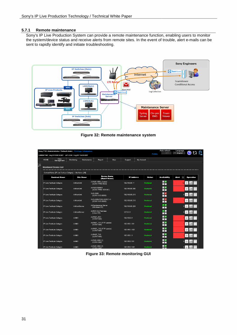
Figure 33: Remote monitoring GUI

Sony’s IP Live Production Technology / Technical White Paper
32
6. CONCLUSION Sony’s IP Live Production System offers a number of significant benefits:
• Integrates file-based systems and live systems on a common network creating better overall ROI • Provides a future-proofed system that caters for future technologies, formats, and trends • Reduces production costs by using the significant benefits of IP
With IP Live, Sony also realizes a number of future capabilities and applications including:
• Agnostic program production, where any type of video or audio content can be incorporated in the same network
• Resource virtualization over the network, realizing a needs-basis culture for system design and architecture, where the system scale and feature set can be changed on a program-by-program basis
• Live production and file-based workflow integration, allowing two disparate production entities to coexist within the same production environment
Sony will continue to provide beneficial solutions for live production systems using standard IT technologies and a unique feature set, losing none of the advantages of current SDI-based systems yet still adding an attractive and compelling set of practical benefits.

Sony’s IP Live Production Technology / Technical White Paper
33
7. REFERENCES 1. Toshiaki Kojima, John J. Stone, Jian-Rong Chen, and Paul N. Gardiner, “A Practical Approach to IP
Live Production”, SMPTE Mot. Imag. J; 124:(2) 29-40, March 2015.
2. P. N. Gardiner1, J. J. Stone1, J-R. Chen1 and T. Kojima2, “IP LIVE PRODUCTION”, 1Sony Europe Ltd, UK and 2Sony Corporation, Japan, IBC 2014
3. IETF RFC 3376. Internet Group Management Protocol (IGMP), Version 3.
4. IEEE 1588-2008. IEEE Standard for a Precision Clock Synchronization Protocol for Networked Measurement and Control Systems.
5. SMPTE ST 2059-2:2015. SMPTE Profile for Use of IEEE-1588 Precision Time Protocol in Professional Broadcast Applications.
6. SMPTE ST 2022-5:2012. Forward Error Correction for High Bit Rate Media Transport over IP.
7. SMPTE ST 2022-6:2012. Transport of High Bit Rate Media Signals over IP Networks (HBRMT).
8. SMPTE ST 2022-7:2013. Seamless Protection Switching of SMPTE ST 2022 IP Datagrams.
9. SMPTE ST 2071-3:2014. Media Device Control Discovery (MDCD)
10. IETF RFC 2474. Definition of the Differentiated Services Field (DS Field) in the IPv4 and IPv6 Headers.
11. AES67-2013: AES standard for audio applications of networks - High-performance streaming audio-over-IP interoperability

Sony’s IP Live Production Technology / Technical White Paper
34
©2017 Sony Imaging Products & Solutions Inc. All rights reserved. Reproduction in whole or in part without written permission is prohibited. Features and specifications are subject to change without notice. “SONY” is a trademark of Sony Corporation. All other trademarks are the property of their respective owners.