Embed Size (px)
DESCRIPTION
Manual de reparo filmadora Sony hd1000
Citation preview
7/18/2019 SONY+HVR-HD1000 SERVICE MANUAL
http://slidepdf.com/reader/full/sonyhvr-hd1000-service-manual 1/425
Revision HistoryRevision History
Sony EMCS Co.
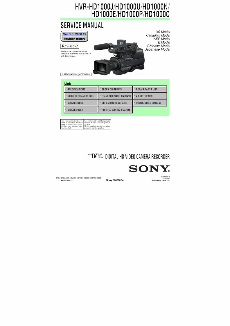
SERVICE MANUAL
Link Link
SERVICE NOTE
DISASSEMBLY PRINTED WIRING BOARDS
MODEL INFORMATION TABLE
SPECIFICATIONS
SCHEMATIC DIAGRAMS
FRAME SCHEMATIC DIAGRAMS
BLOCK DIAGRAMS
ADJUSTMENTS
INSTRUCTION MANUAL
REPAIR PARTS LIST
HVR-HD1000J/HD1000U/HD1000N/HD1000E/HD1000P/HD1000C
Ver. 1.3 2008.12
2008L0500-1 © 2008.12
Published by Kohda TEC9-852-240-13
US Model Canadian Model AEP Model
E Model Chinese Model
Japanese Model
The components identified bymark 0 or dotted line withmark0 are critical for safety.Replace only with part num-ber specified.
Les composants identifiés par unemarque 0 sont critiques pour lasécurité.Ne les remplacer que par une pièceportant le numéro spécifié.
DIGITAL HD VIDEO CAMERA RECORDER
N MECHANISM (MDX-N220)
HVR-HD1000J/HD1000U/HD1000N/ HD1000E/HD1000P/HD1000C
Revised-2
Replace the previously issuedSERVICE MANUAL 9-852-240-12with this manual.
7/18/2019 SONY+HVR-HD1000 SERVICE MANUAL
http://slidepdf.com/reader/full/sonyhvr-hd1000-service-manual 2/425 — 2 —
HVR-HD1000J/HD1000U/HD1000N/HD1000E/HD1000P/HD1000C
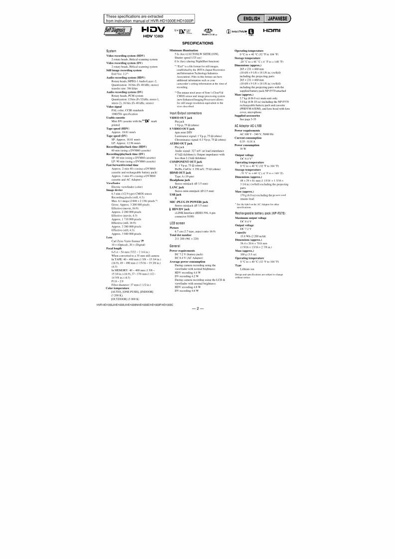
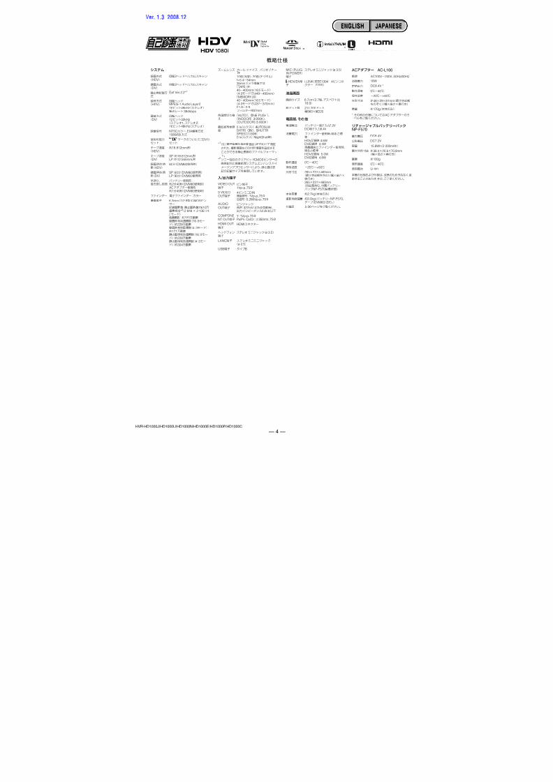
SPECIFICATIONS
These specifications are extractedfrom instruction manual of HVR-HD1000E/HD1000P.
System
Video recording system (HDV)2 rotary heads, Helical scanning system
Video recording system (DV)
2 rotary heads, Helical scanning system
Still image recording system
Exif Ver. 2.2*1
Audio recording system (HDV)
Rotary heads, MPEG-1 Audio Layer -2,
Quantization: 16 bits (Fs 48 kHz, stereo)
transfer rate: 384 kbps
Audio recording system (DV)
Rotary heads, PCM system
Quantization: 12 bits (Fs 32 kHz, stereo 1,
stereo 2), 16 bits (Fs 48 kHz, stereo)
Video signal
PAL color, CCIR standards1080/50i specification
Usable cassette
Mini DV cassette with the mark
printed
Tape speed (HDV)
Approx. 18.81 mm/s
Tape speed (DV)
SP: Approx. 18.81 mm/s
LP: Approx. 12.56 mm/s
Recording/playback time (HDV)
60 min (using a DVM60 cassette)
Recording/playback time (DV)
SP: 60 min (using a DVM60 cassette)
LP: 90 min (using a DVM60 cassette)
Fast forward/rewind time
Approx. 2 min 40 s (using a DVM60
cassette and rechargeable battery pack)
Approx. 1 min 45 s (using a DVM60
cassette and AC Adaptor)
Viewfinder
Electric viewfinder (color)Image device
6.3 mm (1/2.9 type) CMOS sensor
Recording pixels (still, 4:3):
Max. 6.1 mega (2 848 × 2 136) pixels *2
Gross: Approx. 3 200 000 pixels
Effective (movie, 16:9):
Approx. 2 280 000 pixels
Effective (movie, 4:3):
Approx. 1 710 000 pixels
Effective (still, 16:9):Approx. 2 280 000 pixels
Effective (still, 4:3):
Approx. 3 040 000 pixels
Lens
Carl Zeiss Vario-Sonnar T
10 × (Optical), 20 × (Digital)
Focal length
f=5.4 ~ 54 mm (7/32 ~ 2 1/4 in.)
When converted to a 35 mm still camera
In TAPE: 40 ~ 400 mm (1 5/8 ~ 15 3/4 in.)
(16:9), 49 ~ 490 mm (1 15/16 ~ 19 3/8 in.)
(4:3)
In MEMORY: 40 ~ 400 mm (1 5/8 ~
15 3/4 in.) (16:9), 37 ~ 370 mm (1 1/2 ~
14 5/8 in.) (4:3)F1.8 ~ 2.9
Filter diameter: 37 mm (1 1/2 in.)Color temperature
[AUTO], [ONE PUSH], [INDOOR]
(3 200 K),
[OUTDOOR] (5 800 K)
Minimum illumination
5 lx (lux) ([AUTOSLW SHTR] [ON],
Shutter speed 1/25 sec)
0 lx (lux) (during NightShot function)
*1“Exif” is a file format for still images,
established by the JEITA (Japan Electronics
and Information Technology Industries
Association). Files in this format can have
additional information such as your
camcorder’s setting information at the time of
recording.
*2The unique pixel array of Sony’s ClearVid
CMOS sensor and image processing system
(new Enhanced Imaging Processor) allows
for still image resolution equivalent to the
sizes described.
Input/Output connectors
VIDEO OUT jack
Pin jack
1 Vp-p, 75 Ω (ohms)
S VIDEO OUT jack
4pin mini DIN
Luminance signal: 1 Vp-p, 75 Ω (ohms)
Chrominance signal: 0.3 Vp-p, 75 Ω (ohms)
AUDIO OUT jack
Pin jack
Audio signal: 327 mV (at load impedance
47 k Ω (kilohms)), Output impedance with
less than 2.2 k Ω (kilohms)
COMPONENT OUT jack
Y: 1 Vp-p, 75 Ω (ohms)
PB /PR, CB /CR: ± 350 mV, 75 Ω (ohms)
HDMI OUT jack
Type A (19-pin)
Headphone jack
Stereo minijack (Ø 3.5 mm)
LANC jack
Stereo mini-minijack (Ø 2.5 mm)
USB jack
B
MIC (PLUG IN POWER) jack
Stereo minijack (Ø 3.5 mm)
HDV/DV jack
i.LINK Interface (IEEE1394, 4-pin
connector S100)
LCD screenPicture
6.7 cm (2.7 type, aspect ratio 16:9)
Total dot number
211 200 (960 × 220)
General
Power requirements
DC 7.2 V (battery pack)
DC 8.4 V (AC Adaptor)
Average power consumption
During camera recording using the
viewfinder with normal brightness:
HDV recording 4.4 W
DV recording 4.2 W
During camera recording using the LCD &viewfinder with normal brightness:
HDV recording 4.8 W
DV recording 4.6 W
Operating temperature
0°C to + 40
°C (32
°F to 104
°F)Storage temperature
-20 °C to + 60 °C (-4 °F to + 140 °F)
Dimensions (approx.)
265 × 231 × 460 mm
(10 4/8 × 9 1/8 × 18 1/8 in.) (w/h/d)
including the projecting parts
265 × 231 × 460 mm
(10 4/8 × 9 1/8 × 18 1/8 in.) (w/h/d)
including the projecting parts with the
supplied battery pack NP-F570 attached
Mass (approx.)
2.7 kg (6 lb 0 oz) main unit only
3.0 kg (6 lb 10 oz) including the NP-F570
rechargeable battery pack and cassette(PHDVM-63DM), and lens hood with lens
cover, microphone.Supplied accessories
See page 5-35.
AC Adaptor AC-L100
Power requirements
AC 100 V - 240 V, 50/60 Hz
Current consumption
0.35 - 0.18 A
Power consumption
18 W
Output voltage
DC 8.4 V*
Operating temperature
0°C to + 40
°C (32
°F to 104
°F)Storage temperature
-20 °C to + 60 °C (-4 °F to + 140 °F)
Dimensions (approx.)
48 × 29 × 81 mm (1 15/16 × 1 3/16 ×
3 1/4 in.) (w/h/d) excluding the projecting
parts
Mass (approx.)
170 g (6.0 oz) excluding the power cord
(mains lead)
* See the label on the AC Adaptor for otherspecifications.
Rechargeable battery pack (NP-F570)
Maximum output voltage
DC 8.4 V
Output voltage
DC 7.2 V
Capacity
15.8 Wh (2 200 mAh)
Dimensions (approx.)
38.4 × 20.6 × 70.8 mm
(1 9/16 × 13/16 × 2 7/8 in.)
Mass (approx.)
100 g (3.5 oz)
Operating temperature
0 °C to + 40 °C (32 °F to 104 °F)
Type
Lithium ion
Design and specifications are subject to changewithout notice.
ENGLISH JAPANESEENGLISH JAPANESE
7/18/2019 SONY+HVR-HD1000 SERVICE MANUAL
http://slidepdf.com/reader/full/sonyhvr-hd1000-service-manual 3/425 — 3 —
HVR-HD1000J/HD1000U/HD1000N/HD1000E/HD1000P/HD1000C
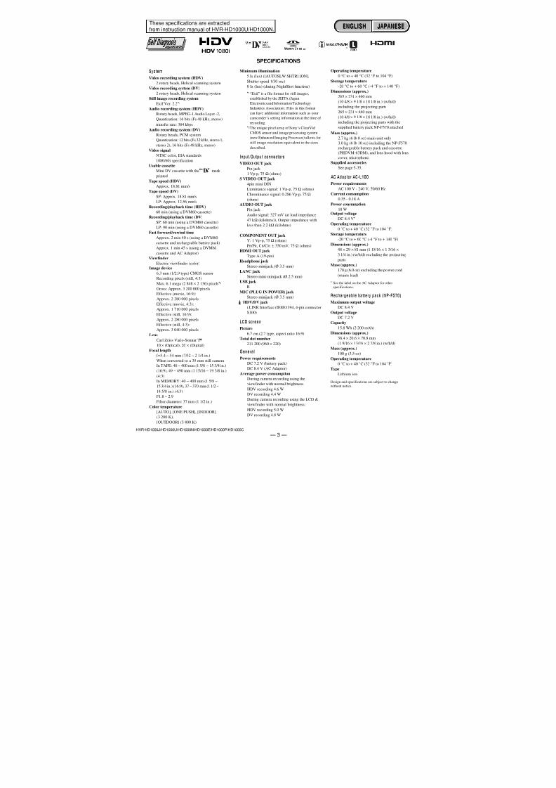
SPECIFICATIONS
These specifications are extractedfrom instruction manual of HVR-HD1000U/HD1000N.
System
Video recording system (HDV)2 rotary heads, Helical scanning system
Video recording system (DV)
2 rotary heads, Helical scanning system
Still image recording system
Exif Ver. 2.2*1
Audio recording system (HDV)
Rotary heads, MPEG-1 Audio Layer -2,
Quantization: 16 bits (Fs 48 kHz, stereo)
transfer rate: 384 kbps
Audio recording system (DV)
Rotary heads, PCM system
Quantization: 12 bits (Fs 32 kHz, stereo 1,
stereo 2), 16 bits (Fs 48 kHz, stereo)
Video signal
NTSC color, EIA standards1080/60i specification
Usable cassette
Mini DV cassette with the mark
printed
Tape speed (HDV)
Approx. 18.81 mm/s
Tape speed (DV)
SP: Approx. 18.81 mm/s
LP: Approx. 12.56 mm/s
Recording/playback time (HDV)
60 min (using a DVM60 cassette)
Recording/playback time (DV)
SP: 60 min (using a DVM60 cassette)
LP: 90 min (using a DVM60 cassette)
Fast forward/rewind time
Approx. 2 min 40 s (using a DVM60
cassette and rechargeable battery pack)
Approx. 1 min 45 s (using a DVM60
cassette and AC Adaptor)
Viewfinder
Electric viewfinder (color)Image device
6.3 mm (1/2.9 type) CMOS sensor
Recording pixels (still, 4:3):
Max. 6.1 mega (2 848 × 2 136) pixels*2
Gross: Approx. 3 200 000 pixels
Effective (movie, 16:9):
Approx. 2 280 000 pixels
Effective (movie, 4:3):
Approx. 1 710 000 pixels
Effective (still, 16:9):Approx. 2 280 000 pixels
Effective (still, 4:3):
Approx. 3 040 000 pixels
Lens
Carl Zeiss Vario-Sonnar T
10 × (Optical), 20 × (Digital)
Focal length
f=5.4 ~ 54 mm (7/32 ~ 2 1/4 in.)
When converted to a 35 mm still camera
In TAPE: 40 ~ 400 mm (1 5/8 ~ 15 3/4 in.)
(16:9), 49 ~ 490 mm (1 15/16 ~ 19 3/8 in.)
(4:3)
In MEMORY: 40 ~ 400 mm (1 5/8 ~
15 3/4 in.) (16:9), 37 ~ 370 mm (1 1/2 ~
14 5/8 in.) (4:3)F1.8 ~ 2.9
Filter diameter: 37 mm (1 1/2 in.)
Color temperature
[AUTO], [ONE PUSH], [INDOOR]
(3 200 K),
[OUTDOOR] (5 800 K)
Minimum illumination
5 lx (lux) ([AUTOSLW SHTR] [ON],
Shutter speed 1/30 sec)
0 lx (lux) (during NightShot function)
*1“Exif” is a file format for still images,
established by the JEITA (Japan
Electronics and Information Technology
Industries Association). Files in this format
can have additional information such as your
camcorder’s setting information at the time of
recording.
*2The unique pixel array of Sony’s ClearVid
CMOS sensor and image processing system
(new Enhanced Imaging Processor) allows for
still image resolution equivalent to the sizes
described.
Input/Output connectorsVIDEO OUT jack
Pin jack
1 Vp-p, 75 Ω (ohms)
S VIDEO OUT jack
4pin mini DIN
Luminance signal: 1 Vp-p, 75 Ω (ohms)
Chrominance signal: 0.286 Vp-p, 75 Ω
(ohms)
AUDIO OUT jack
Pin jack
Audio signal: 327 mV (at load impedance
47 k Ω (kilohms)), Output impedance with
less than 2.2 k Ω (kilohms)
COMPONENT OUT jackY: 1 Vp-p, 75 Ω (ohms)
PB /PR, CB /CR: ± 350 mV, 75 Ω (ohms)
HDMI OUT jack
Type A (19-pin)
Headphone jack
Stereo minijack (Ø 3.5 mm)
LANC jack
Stereo mini-minijack (Ø 2.5 mm)
USB jack
B
MIC (PLUG IN POWER) jack
Stereo minijack (Ø 3.5 mm)
HDV/DV jack
i.LINK Interface (IEEE1394, 4-pin connector
S100)
LCD screen
Picture
6.7 cm (2.7 type, aspect ratio 16:9)
Total dot number
211 200 (960 × 220)
General
Power requirements
DC 7.2 V (battery pack)
DC 8.4 V (AC Adaptor)
Average power consumption
During camera recording using the
viewfinder with normal brightness:
HDV recording 4.6 W
DV recording 4.4 WDuring camera recording using the LCD &
viewfinder with normal brightness:
HDV recording 5.0 W
DV recording 4.8 W
Operating temperature
0 °C to + 40 °C (32 °F to 104 °F)
Storage temperature
-20 °C to + 60 °C (-4 °F to + 140 °F)
Dimensions (approx.)
265 × 231 × 460 mm
(10 4/8 × 9 1/8 × 18 1/8 in.) (w/h/d)
including the projecting parts
265 × 231 × 460 mm
(10 4/8 × 9 1/8 × 18 1/8 in.) (w/h/d)
including the projecting parts with the
supplied battery pack NP-F570 attached
Mass (approx.)
2.7 kg (6 lb 0 oz) main unit only
3.0 kg (6 lb 10 oz) including the NP-F570
rechargeable battery pack and cassette(PHDVM-63DM), and lens hood with lens
cover, microphone.Supplied accessories
See page 5-35.
AC Adaptor AC-L100
Power requirements
AC 100 V - 240 V, 50/60 Hz
Current consumption
0.35 - 0.18 A
Power consumption
18 WOutput voltage
DC 8.4 V*
Operating temperature
0 °C to + 40 °C (32 °F to 104 °F)
Storage temperature-20 °C to + 60 °C (-4 °F to + 140 °F)
Dimensions (approx.)
48 × 29 × 81 mm (1 15/16 × 1 3/16 ×
3 1/4 in.) (w/h/d) excluding the projecting
parts
Mass (approx.)
170 g (6.0 oz) excluding the power cord
(mains lead)
* See the label on the AC Adaptor for otherspecifications.
Rechargeable battery pack (NP-F570)
Maximum output voltage
DC 8.4 V
Output voltage
DC 7.2 V
Capacity
15.8 Wh (2 200 mAh)
Dimensions (approx.)
38.4 × 20.6 × 70.8 mm
(1 9/16 × 13/16 × 2 7/8 in.) (w/h/d)
Mass (approx.)
100 g (3.5 oz)
Operating temperature
0 °C to + 40 °C (32 °F to 104 °F)
Type
Lithium ion
Design and specifications are subject to changewithout notice.
ENGLISH JAPANESEENGLISH JAPANESE
7/18/2019 SONY+HVR-HD1000 SERVICE MANUAL
http://slidepdf.com/reader/full/sonyhvr-hd1000-service-manual 4/425 — 4 —
HVR-HD1000J/HD1000U/HD1000N/HD1000E/HD1000P/HD1000C
ENGLISH JAPANESEENGLISH JAPANESE
Ver. 1.3 2008.12
HDV
2
DV
2
Exif Ver.2.2*1
HDV
MPEG-1 Audio Layer2
1648kHz
384kbps
DV
1232kHz12
1648kHz
NTSCEIA
1080/60i
DV
HDV
18.812mm/
DV
SP18.812mm/ LP12.555mm/
/
HDV60DVM60
/
DVSP60DVM60
LP90DVM60
240DVM60
AC
145DVM60
6.3mm1/2.9CMOS
610
*22 848 2 13643
320
169228
43
171
16922843
304
/
T
10
20
f=5.454mm35mm
TAPE
40400mm16:94:349490mm
MEMORY
40400mm16:9
4:337370
F1.82.937mm
AUTO ONE PUSH
INDOOR3 200K
OUTDOOR5 800K
5 lx AUTOSLWSHTRON SHUTTRSPEED1/30
0 lx NightShot
*1JEITA
*2
CMOS
VIDEO OUT
1Vp-p75
S VIDEOOUT
4DIN1Vp-p750.286Vp-p75
AUDIOOUT
327mV47k2.2k
COMPONENT OUT
Y1Vp-p75PB /PR. CB /CR350mV75
HDMI OUT
HDMI
ø 3.5
LANC
ø 2.5
USB B
MICPLUGIN POWER
ø 3.5
HDV/DV
i.LINKIEEE1394 4
S100
6.7cm2.7
16:9
211 200
960220
7.2VDC8.4V
HDV 4.6WDV 4.4W
HDV 5.0WDV 4.8W
040
20+60
265231460mm
265231460mm
NP-F570
2.7kg
3.0kg
5-36
NP-F570DVM60
AC AC-L100
* AC
NP-F570
AC100V
240V
50Hz/60Hz
18W
DC8.4V *
040
20+60
482981mm
170g
DC8.4V
DC7.2V
15.8Wh2 200mAh
38.420.670.8mm
100g
040
Li-ion
7/18/2019 SONY+HVR-HD1000 SERVICE MANUAL
http://slidepdf.com/reader/full/sonyhvr-hd1000-service-manual 5/425 — 5 —
HVR-HD1000J/HD1000U/HD1000N/HD1000E/HD1000P/HD1000C
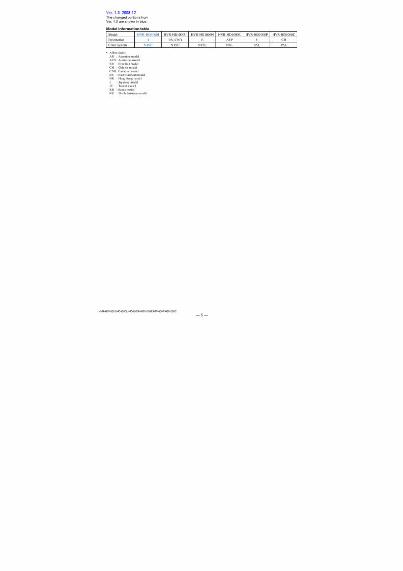
• Abbreviation
AR : Argentine modelAUS : Australian model
BR : Brazilian model
CH : Chinese modelCND : Canadian model
EE : East European model
HK : Hong Kong model
J : Japanese modelJE : Tourist model
KR : Korea model
NE : North European model
Model information tableModel HVR-HD1000J HVR-HD1000U HVR-HD1000N HVR-HD1000E HVR-HD1000P HVR-HD1000C
Destination J US, CND E AEP E CH
Color system NTSC NTSC NTSC PAL PAL PAL
Ver. 1.3 2008.12The changed portions fromVer. 1.2 are shown in blue.
7/18/2019 SONY+HVR-HD1000 SERVICE MANUAL
http://slidepdf.com/reader/full/sonyhvr-hd1000-service-manual 6/425 — 6 —
HVR-HD1000J/HD1000U/HD1000N/HD1000E/HD1000P/HD1000C
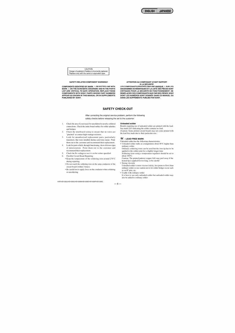
SAFETY-RELATED COMPONENT WARNING!!
COMPONENTS IDENTIFIED BY MARK0 OR DOTTED LINE WITHMARK 0 ON THE SCHEMATIC DIAGRAMS AND IN THE PARTSLIST ARE CRITICAL TO SAFE OPERATION. REPLACE THESECOMPONENTS WITH SONY PARTS WHOSE PART NUMBERSAPPEAR AS SHOWN IN THIS MANUAL OR IN SUPPLEMENTSPUBLISHED BY SONY.
1. Check the area of your repair for unsoldered or poorly-soldered
connections. Check the entire board surface for solder splashes
and bridges.
2. Check the interboard wiring to ensure that no wires are
"pinched" or contact high-wattage resistors.
3. Look for unauthorized replacement parts, particularly
transistors, that were installed during a previous repair. Point
them out to the customer and recommend their replacement.
4. Look for parts which, through functioning, show obvious signs
of deterioration. Point them out to the customer and
recommend their replacement.
5. Check the B+ voltage to see it is at the values specified.
6. Flexible Circuit Board Repairing
• Keep the temperature of the soldering iron around 270˚C
during repairing.
• Do not touch the soldering iron on the same conductor of the
circuit board (within 3 times).• Be careful not to apply force on the conductor when soldering
or unsoldering.
Unleaded solderBoards requiring use of unleaded solder are printed with the lead-
free mark (LF) indicating the solder contains no lead.
(Caution: Some printed circuit boards may not come printed with
the lead free mark due to their particular size.)
: LEAD FREE MARKUnleaded solder has the following characteristics.
• Unleaded solder melts at a temperature about 40°C higher thanordinary solder.
Ordinary soldering irons can be used but the iron tip has to be
applied to the solder joint for a slightly longer time.
Soldering irons using a temperature regulator should be set to
about 350°C.
Caution: The printed pattern (copper foil) may peel away if the
heated tip is applied for too long, so be careful!• Strong viscosity
Unleaded solder is more viscous (sticky, less prone to flow) thanordinary solder so use caution not to let solder bridges occur such
as on IC pins, etc.
• Usable with ordinary solder
It is best to use only unleaded solder but unleaded solder may
also be added to ordinary solder.
SAFETY CHECK-OUT
After correcting the original service problem, perform the following
safety checks before releasing the set to the customer.
CAUTIONDanger of explosion if battery is incorrectly replaced.Replace only with the same or equivalent type.
ATTENTION AU COMPOSANT AYANT RAPPORTÀ LA SÉCURITÉ!
LES COMPOSANTS IDENTIFÉS PAR UNE MARQUE0 SUR LESDIAGRAMMES SCHÉMATIQUES ET LA LISTE DES PIÈCES SONTCRITIQUES POUR LA SÉCURITÉ DE FONCTIONNEMENT. NEREMPLACER CES COMPOSANTS QUE PAR DES PIÈSES SONYDONT LES NUMÉROS SONT DONNÉS DANS CE MANUEL OUDANS LES SUPPÉMENTS PUBLIÉS PAR SONY.
ENGLISH JAPANESEENGLISH JAPANESE
7/18/2019 SONY+HVR-HD1000 SERVICE MANUAL
http://slidepdf.com/reader/full/sonyhvr-hd1000-service-manual 7/425 — 7 —
HVR-HD1000J/HD1000U/HD1000N/HD1000E/HD1000P/HD1000C
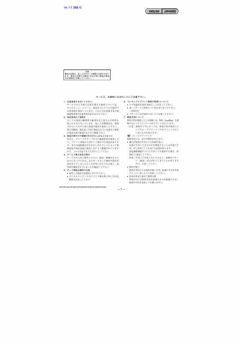
0
•
•
•
•
•
•
•
•
ENGLISH JAPANESEENGLISH JAPANESE
Ver. 1.3 2008.12
7/18/2019 SONY+HVR-HD1000 SERVICE MANUAL
http://slidepdf.com/reader/full/sonyhvr-hd1000-service-manual 8/4251-1HVR-HD1000J/HD1000U/HD1000N/HD1000E/HD1000P/HD1000C
1. SERVICE NOTE
1-1. POWER SUPPLY DURING REPAIRSIn this unit, about 10 seconds after power is supplied to the battery terminal using the regulated power supply (8.4 V), the power is shut off so
that the unit cannot operate.
These following method is available to prevent this.
Method:Use the AC power adaptor (AC-L100).
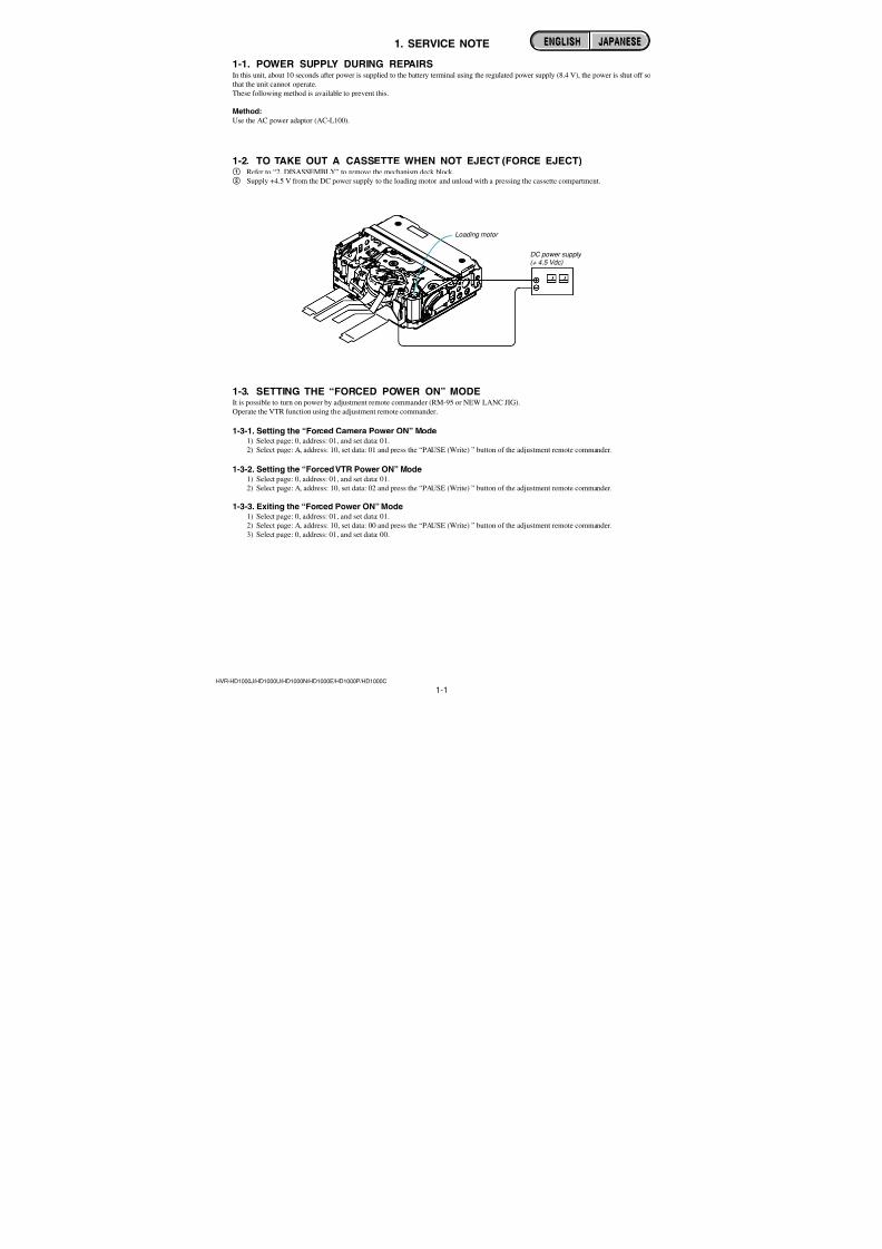
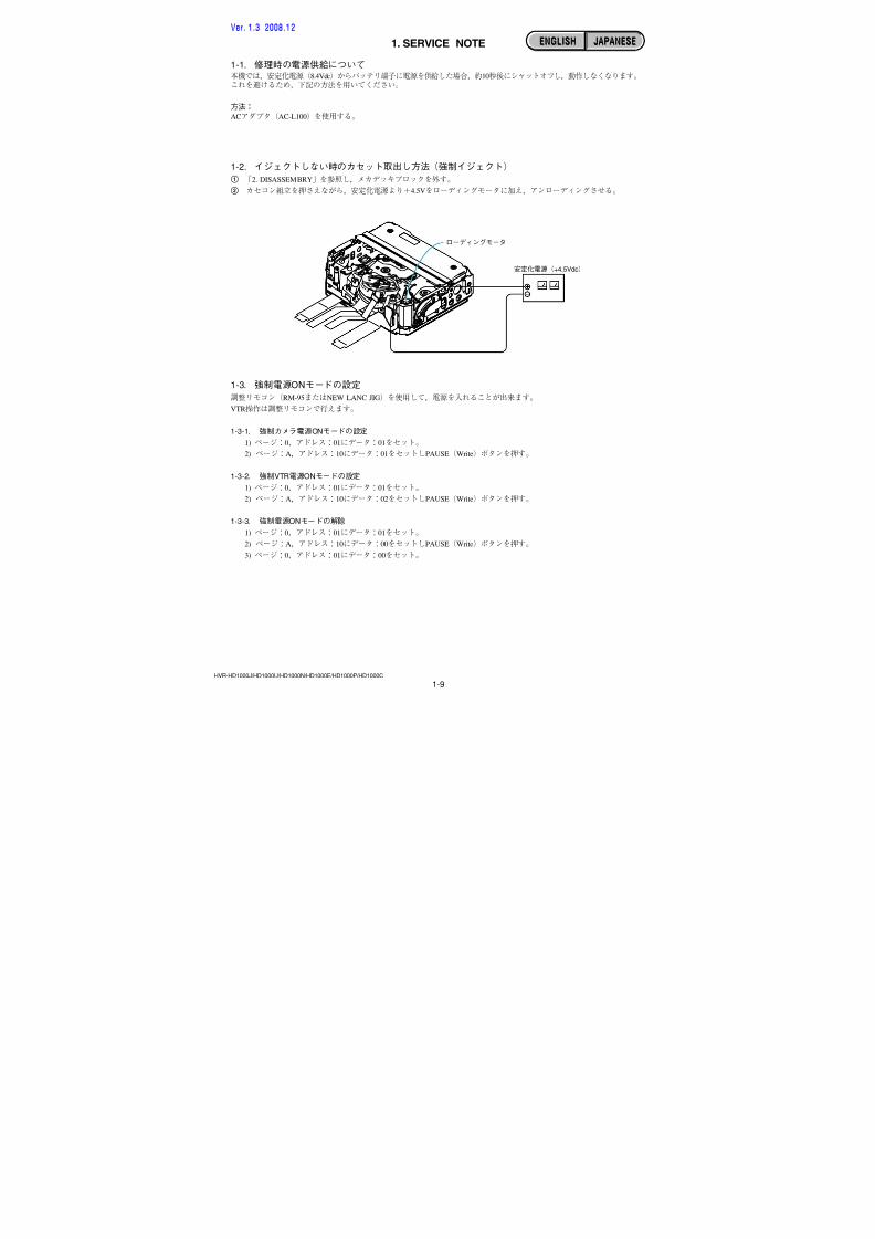
1-2. TO TAKE OUT A CASSETTE WHEN NOT EJECT (FORCE EJECT)1 Refer to “2. DISASSEMBLY” to remove the mechanism deck block.
2 Supply +4.5 V from the DC power supply to the loading motor and unload with a pressing the cassette compartment.
Loading motor
DC power supply (+ 4.5 Vdc)
1-3. SETTING THE “FORCED POWER ON” MODEIt is possible to turn on power by adjustment remote commander (RM-95 or NEW LANC JIG).
Operate the VTR function using the adjustment remote commander.
1-3-1. Setting the “Forced Camera Power ON” Mode1) Select page: 0, address: 01, and set data: 01.
2) Select page: A, address: 10, set data: 01 and press the “PAUSE (Write) ” button of the adjustment remote commander.
1-3-2. Setting the “Forced VTR Power ON” Mode1) Select page: 0, address: 01, and set data: 01.
2) Select page: A, address: 10, set data: 02 and press the “PAUSE (Write) ” button of the adjustment remote commander.
1-3-3. Exiting the “Forced Power ON” Mode1) Select page: 0, address: 01, and set data: 01.
2) Select page: A, address: 10, set data: 00 and press the “PAUSE (Write) ” button of the adjustment remote commander.
3) Select page: 0, address: 01, and set data: 00.
ENGLISH JAPANESEENGLISH JAPANESE
7/18/2019 SONY+HVR-HD1000 SERVICE MANUAL
http://slidepdf.com/reader/full/sonyhvr-hd1000-service-manual 9/4251-2HVR-HD1000J/HD1000U/HD1000N/HD1000E/HD1000P/HD1000C
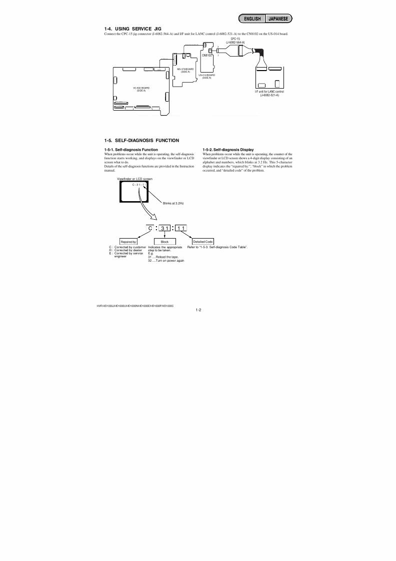
1-5. SELF-DIAGNOSIS FUNCTION
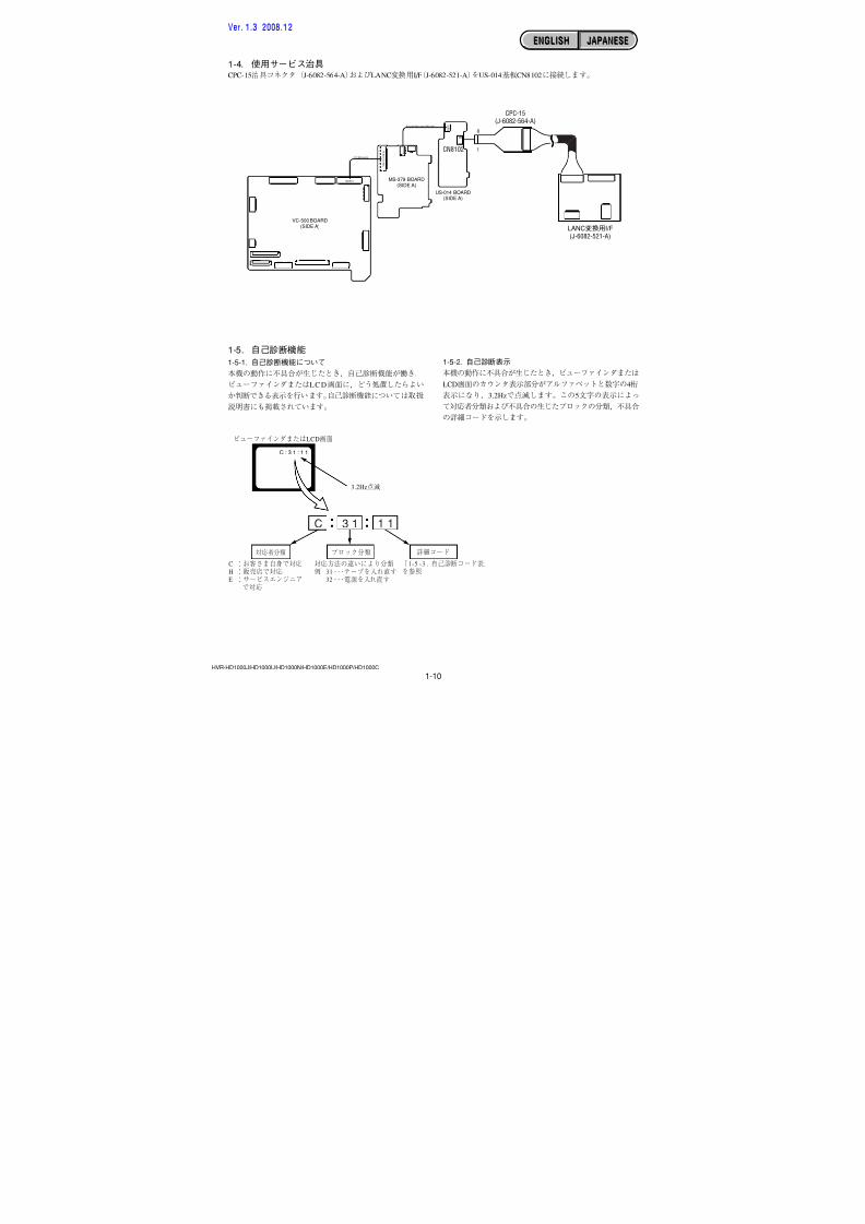
1-5-1. Self-diagnosis FunctionWhen problems occur while the unit is operating, the self-diagnosisfunction starts working, and displays on the viewfinder or LCD
screen what to do.
Details of the self-diagnosis functions are provided in the Instructionmanual.
1-5-2. Self-diagnosis DisplayWhen problems occur while the unit is operating, the counter of theviewfinder or LCD screen shows a 4-digit display consisting of an
alphabet and numbers, which blinks at 3.2 Hz. This 5-character
display indicates the “repaired by:”, “block” in which the problemoccurred, and “detailed code” of the problem.
1 13 1C
Repaired by:
Refer to “1-5-3. Self-diagnosis Code Table”.Indicates the appropriatestep to be taken.E.g.31 ....Reload the tape.32 ....Turn on power again.
Block Detailed Code
Blinks at 3.2Hz
C : Corrected by customerH : Corrected by dealerE : Corrected by service
engineer
Viewfinder or LCD screen
C : 3 1 : 1 1
1-4. USING SERVICE JIGConnect the CPC-15 jig connector (J-6082-564-A) and I/F unit for LANC control (J-6082-521-A) to the CN8102 on the US-014 board.
C N 8 0 0 1
( S I D E
B )
CN1012
FLexible Flat Cable (FFC-107)
FP-786 Flexible
C N 8 1 0 1
C N 8 0
0 3
1
8
1
8
VC-500 BOARD(SIDE A)
CPC-15(J-6082-564-A)
I/F unit for LANC control(J-6082-521-A)
MS-379 BOARD(SIDE A)
US-014 BOARD(SIDE A)
CN8102
ENGLISH JAPANESEENGLISH JAPANESE
7/18/2019 SONY+HVR-HD1000 SERVICE MANUAL
http://slidepdf.com/reader/full/sonyhvr-hd1000-service-manual 10/4251-3HVR-HD1000J/HD1000U/HD1000N/HD1000E/HD1000P/HD1000C
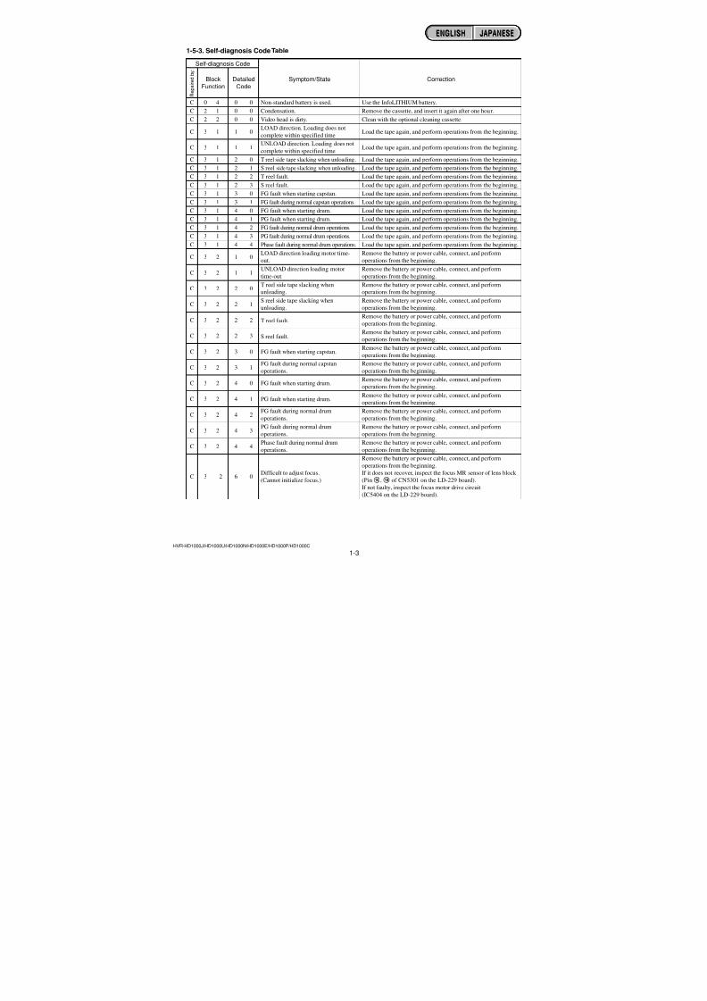
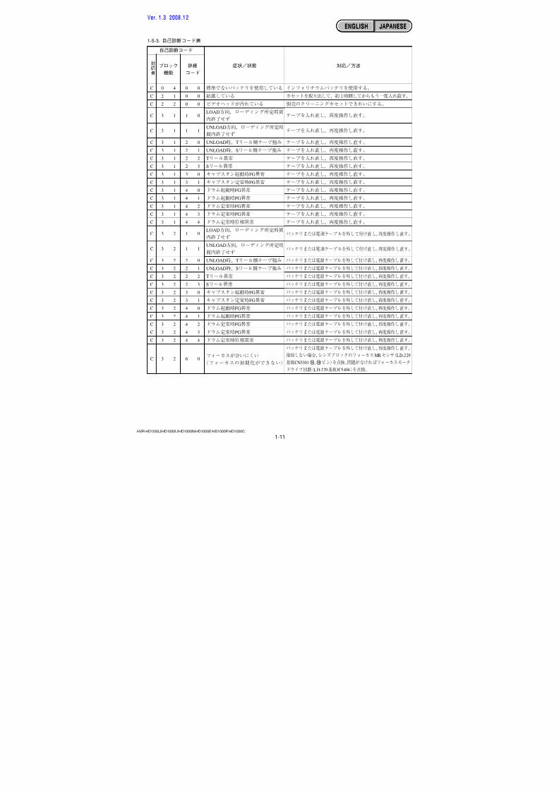
1-5-3. Self-diagnosis Code Table
C
C
C
C
C
C
C
C
C
C
C
C
C
C
C
C
C
C
C
C
C
C
C
C
C
C
C
C
C
C
BlockFunction
0 4
2 1
2 2
3 1
3 1
3 1
3 1
3 1
3 1
3 1
3 1
3 1
3 1
3 1
3 1
3 1
3 2
3 2
3 2
3 2
3 2
3 2
3 2
3 2
3 2
3 2
3 2
3 2
3 2
3 2
DetailedCode
0 0
0 0
0 0
1 0
1 1
2 0
2 1
2 2
2 3
3 0
3 1
4 0
4 1
4 2
4 3
4 4
1 0
1 1
2 0
2 1
2 2
2 3
3 0
3 1
4 0
4 1
4 2
4 3
4 4
6 0
Symptom/State
Non-standard battery is used.
Condensation.
Video head is dirty.
LOAD direction. Loading does not
complete within specified time
UNLOAD direction. Loading does not
complete within specified time
T reel side tape slacking when unloading.
S reel side tape slacking when unloading.
T reel fault.
S reel fault.
FG fault when starting capstan.
FG fault during normal capstan operations.
FG fault when starting drum.
PG fault when starting drum.
FG fault during normal drum operations.
PG fault during normal drum operations.
Phase fault during normal drum operations.
LOAD direction loading motor time-
out.
UNLOAD direction loading motor
time-out.
T reel side tape slacking whenunloading.
S reel side tape slacking whenunloading.
T reel fault.
S reel fault.
FG fault when starting capstan.
FG fault during normal capstan
operations.
FG fault when starting drum.
PG fault when starting drum.
FG fault during normal drum
operations.
PG fault during normal drum
operations.
Phase fault during normal drum
operations.
Difficult to adjust focus.
(Cannot initialize focus.)
Self-diagnosis Code
Repairedby:
Correction
Use the InfoLITHIUM battery.
Remove the cassette, and insert it again after one hour.
Clean with the optional cleaning cassette.
Load the tape again, and perform operations from the beginning.
Load the tape again, and perform operations from the beginning.
Load the tape again, and perform operations from the beginning.
Load the tape again, and perform operations from the beginning.
Load the tape again, and perform operations from the beginning.
Load the tape again, and perform operations from the beginning.
Load the tape again, and perform operations from the beginning.
Load the tape again, and perform operations from the beginning.
Load the tape again, and perform operations from the beginning.
Load the tape again, and perform operations from the beginning.
Load the tape again, and perform operations from the beginning.
Load the tape again, and perform operations from the beginning.
Load the tape again, and perform operations from the beginning.
Remove the battery or power cable, connect, and perform
operations from the beginning.
Remove the battery or power cable, connect, and perform
operations from the beginning.
Remove the battery or power cable, connect, and performoperations from the beginning.
Remove the battery or power cable, connect, and performoperations from the beginning.
Remove the battery or power cable, connect, and perform
operations from the beginning.
Remove the battery or power cable, connect, and performoperations from the beginning.
Remove the battery or power cable, connect, and perform
operations from the beginning.
Remove the battery or power cable, connect, and perform
operations from the beginning.
Remove the battery or power cable, connect, and performoperations from the beginning.
Remove the battery or power cable, connect, and perform
operations from the beginning.
Remove the battery or power cable, connect, and perform
operations from the beginning.
Remove the battery or power cable, connect, and perform
operations from the beginning.
Remove the battery or power cable, connect, and perform
operations from the beginning.
Remove the battery or power cable, connect, and perform
operations from the beginning.
If it does not recover, inspect the focus MR sensor of lens block
(Pin qh, qk of CN5301 on the LD-229 board).
If not faulty, inspect the focus motor drive circuit
(IC5404 on the LD-229 board).
ENGLISH JAPANESEENGLISH JAPANESE
7/18/2019 SONY+HVR-HD1000 SERVICE MANUAL
http://slidepdf.com/reader/full/sonyhvr-hd1000-service-manual 11/4251-4HVR-HD1000J/HD1000U/HD1000N/HD1000E/HD1000P/HD1000C
E
E
E
E
E
E
E
E
E
E
BlockFunction
6 1
6 1
6 2
6 2
6 2
6 2
6 2
6 2
6 2
6 2
DetailedCode
1 0
1 1
0 0
0 1
0 2
0 3
1 0
1 1
1 2
2 0
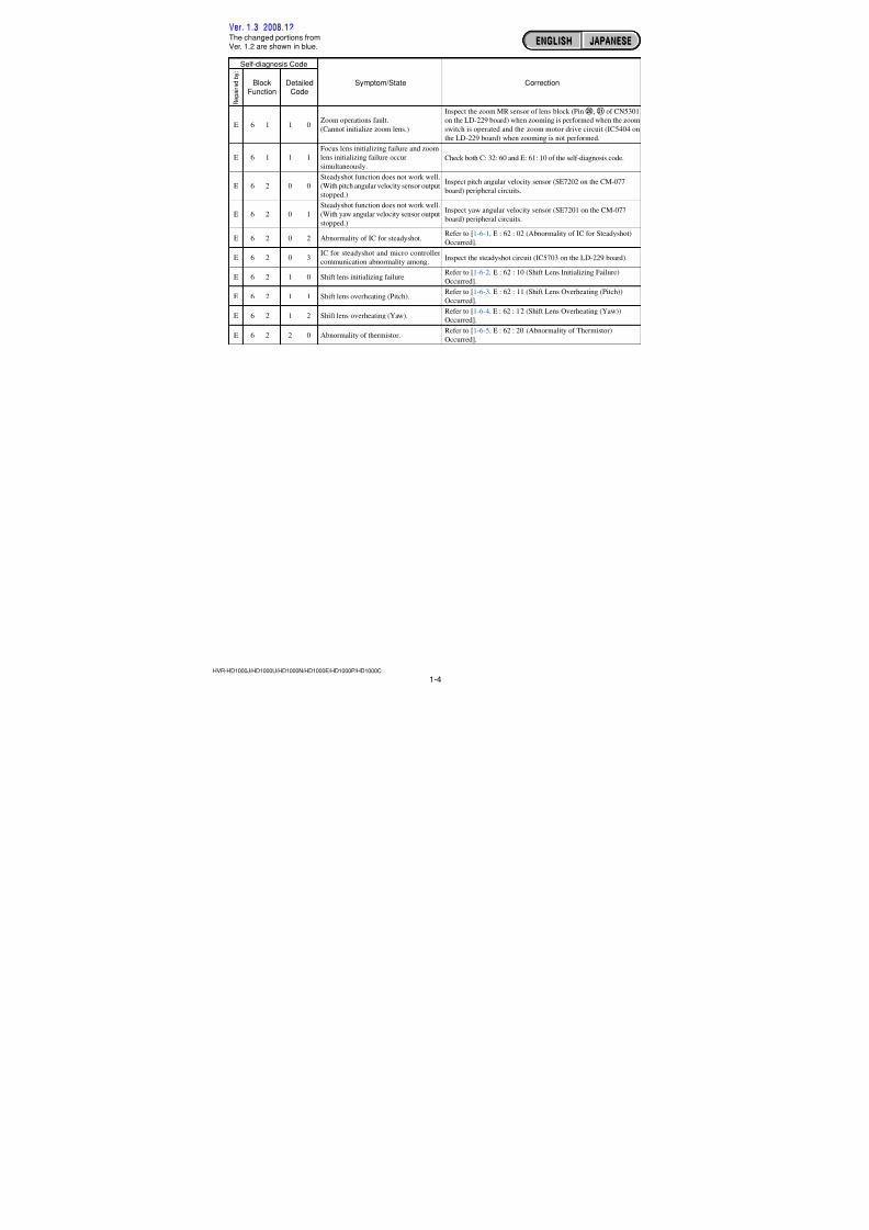
Symptom/State
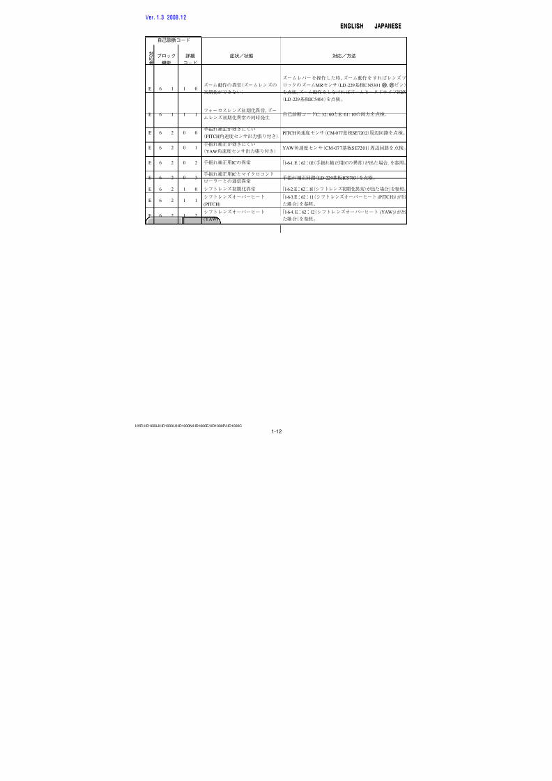
Zoom operations fault.(Cannot initialize zoom lens.)
Focus lens initializing failure and zoom
lens initializing failure occur
simultaneously.
Steadyshot function does not work well.
(With pitch angular velocity sensor output
stopped.)
Steadyshot function does not work well.
(With yaw angular velocity sensor output
stopped.)
Abnormality of IC for steadyshot.
IC for steadyshot and micro controller
communication abnormality among.
Shift lens initializing failure.
Shift lens overheating (Pitch).
Shift lens overheating (Yaw).
Abnormality of thermistor.
Self-diagnosis Code
Repairedby:
Correction
Inspect the zoom MR sensor of lens block (Pin w;, wa of CN5301
on the LD-229 board) when zooming is performed when the zoomswitch is operated and the zoom motor drive circuit (IC5404 on
the LD-229 board) when zooming is not performed.
Check both C: 32: 60 and E: 61: 10 of the self-diagnosis code.
Inspect pitch angular velocity sensor (SE7202 on the CM-077
board) peripheral circuits.
Inspect yaw angular velocity sensor (SE7201 on the CM-077
board) peripheral circuits.
Refer to [1-6-1. E : 62 : 02 (Abnormality of IC for Steadyshot)
Occurred].
Inspect the steadyshot circuit (IC5703 on the LD-229 board).
Refer to [1-6-2. E : 62 : 10 (Shift Lens Initializing Failure)
Occurred].
Refer to [1-6-3. E : 62 : 11 (Shift Lens Overheating (Pitch))
Occurred].
Refer to [1-6-4. E : 62 : 12 (Shift Lens Overheating (Yaw))
Occurred].
Refer to [1-6-5. E : 62 : 20 (Abnormality of Thermistor)
Occurred].
ENGLISH JAPANESEENGLISH JAPANESE
Ver. 1.3 2008.12
The changed portions fromVer. 1.2 are shown in blue.
7/18/2019 SONY+HVR-HD1000 SERVICE MANUAL
http://slidepdf.com/reader/full/sonyhvr-hd1000-service-manual 12/4251-5HVR-HD1000J/HD1000U/HD1000N/HD1000E/HD1000P/HD1000C
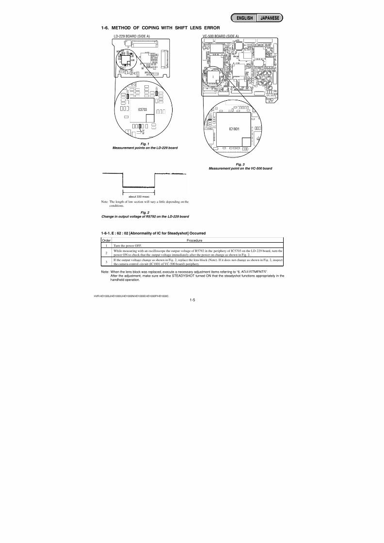
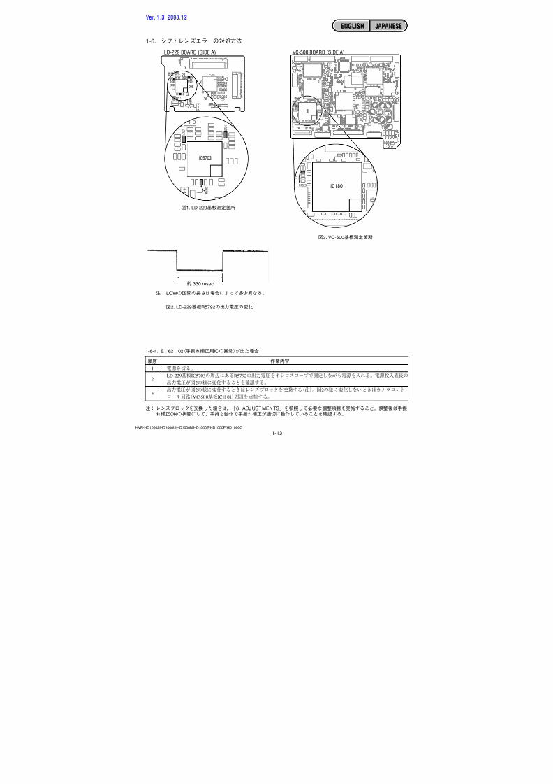
1-6. METHOD OF COPING WITH SHIFT LENS ERROR
about 330 msec
Fig. 1Measurement points on the LD-229 board
R 5 7 9 2
IC5703
R 5 7 2 1
R 5 7 3 7
LD-229 BOARD (SIDE A)
Fig. 2
Change in output voltage of R5792 on the LD-229 board
Note: The length of low section will vary a little depending on the
conditions.
1-6-1. E : 62 : 02 [Abnormality of IC for Steadyshot] Occurred
Order Procedure
1 Turn the power OFF.
2While measuring with an oscilloscope the output voltage of R5792 in the periphery of IC5703 on the LD-229 board, turn the
power ON to check that the output voltage immediately after the power on change as shown in Fig. 2.
3If the output voltage change as shown in Fig. 2, replace the lens block (Note). If it does not change as shown in Fig. 2, inspect
the camera control circuit (IC1801 of VC-500 board) periphery.
Note: When the lens block was replaced, execute a necessary adjustment items referring to “6. ADJUSTMENTS”.After the adjustment, make sure with the STEADYSHOT turned ON that the steadyshot functions appropriately in thehandheld operation.
IC1801R1823
I
C
R 8 3
VC-500 BOARD (SIDE A)
Fig. 3 Measurement point on the VC-500 board
ENGLISH JAPANESEENGLISH JAPANESE
7/18/2019 SONY+HVR-HD1000 SERVICE MANUAL
http://slidepdf.com/reader/full/sonyhvr-hd1000-service-manual 13/4251-6HVR-HD1000J/HD1000U/HD1000N/HD1000E/HD1000P/HD1000C
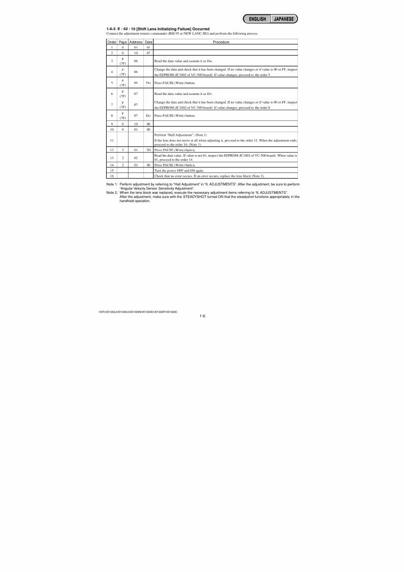
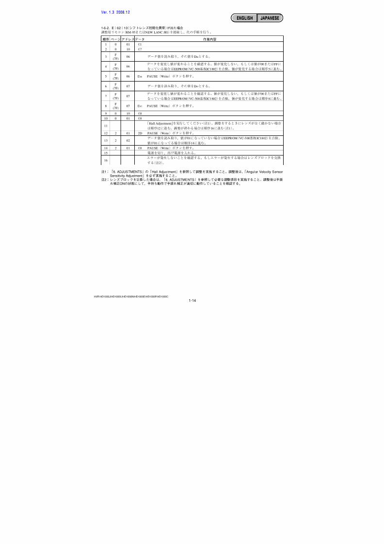
1-6-2. E : 62 : 10 [Shift Lens Initializing Failure] OccurredConnect the adjustment remote commander (RM-95 or NEW LANC JIG) and perform the following process.
Order Page Address Data Procedure
1 0 01 01
2 0 10 07
3F
06 Read the data value and assume it as D06.(7F)
4F
06Change the data and check that it has been changed. If no value changes or if value is 00 or FF, inspect
(7F) the EEPROM (IC1802 of VC-500 board). If value changes, proceed to the order 5.
5F
06 D06 Press PAUSE (Write) button.(7F)
6F
07 Read the data value and assume it as D07.(7F)
7F
07Change the data and check that it has been changed. If no value changes or if value is 00 or FF, inspect
(7F) the EEPROM (IC1802 of VC-500 board). If value changes, proceed to the order 8.
8 F 07 D07 Press PAUSE (Write) button.(7F)
9 0 10 00
10 0 01 00
Perform “Hall Adjustment”. (Note 1)
11 If the lens does not move at all when adjusting it, proceed to the order 12. When the adjustment ends,
proceed to the order 16. (Note 1)
12 2 01 2D Press PAUSE (Write) button.
13 2 02Read the data value. If value is not 01, inspect the EEPROM (IC1802 of VC-500 board). When value is
01, proceed to the order 14.
14 2 01 00 Press PAUSE (Write) button.
15 Turn the power OFF and ON again.16 Check that no error occurs. If an error occurs, replace the lens block (Note 2).
Note 1: Perform adjustment by referring to “Hall Adjustment” in “6. ADJUSTMENTS”. After the adjustment, be sure to perform“Angular Velocity Sensor Sensitivity Adjustment”.
Note 2: When the lens block was replaced, execute the necessary adjustment items referring to “6. ADJUSTMENTS”.After the adjustment, make sure with the STEADYSHOT turned ON that the steadyshot functions appropriately in thehandheld operation.
ENGLISH JAPANESEENGLISH JAPANESE
7/18/2019 SONY+HVR-HD1000 SERVICE MANUAL
http://slidepdf.com/reader/full/sonyhvr-hd1000-service-manual 14/4251-7HVR-HD1000J/HD1000U/HD1000N/HD1000E/HD1000P/HD1000C
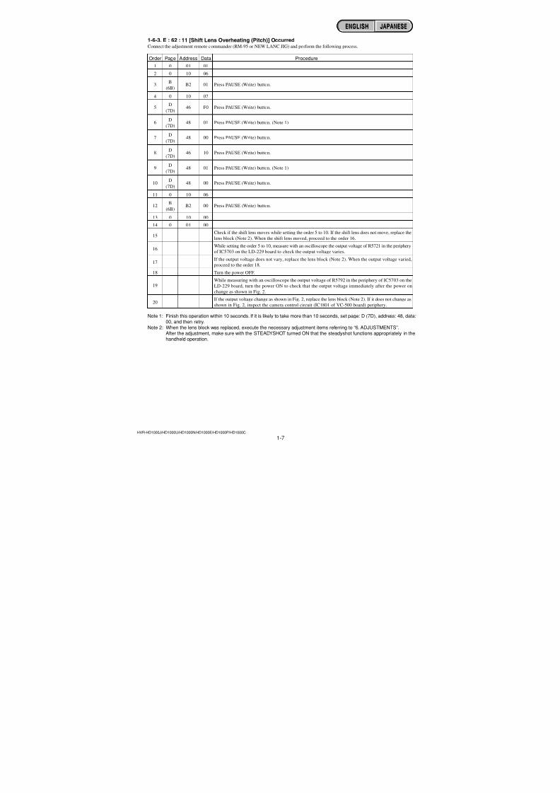
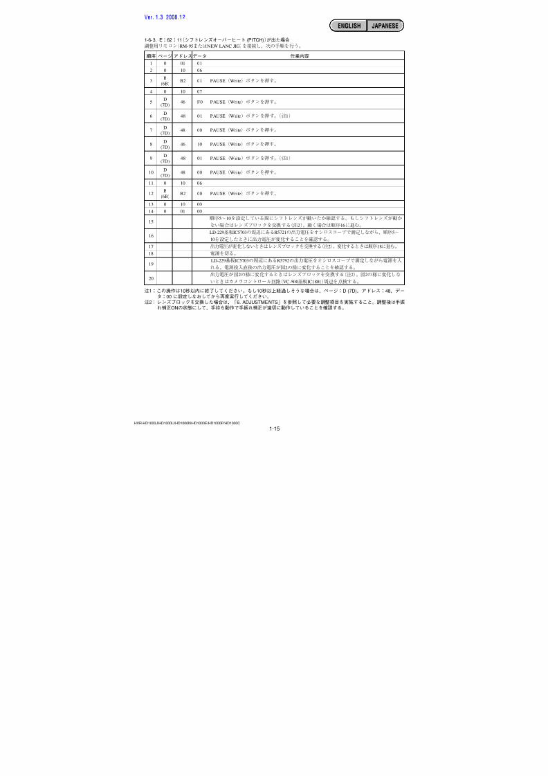
1-6-3. E : 62 : 11 [Shift Lens Overheating (Pitch)] OccurredConnect the adjustment remote commander (RM-95 or NEW LANC JIG) and perform the following process.
Order Page Address Data Procedure
1 0 01 01
2 0 10 06
3B
B2 01 Press PAUSE (Write) button.(6B)
4 0 10 07
5D
46 F0 Press PAUSE (Write) button.(7D)
6D
48 01 Press PAUSE (Write) button. (Note 1)(7D)
7D
48 00 Press PAUSE (Write) button.(7D)
8D
46 10 Press PAUSE (Write) button.
(7D)
9D
48 01 Press PAUSE (Write) button. (Note 1)(7D)
10D
48 00 Press PAUSE (Write) button.(7D)
11 0 10 06
12B
B2 00 Press PAUSE (Write) button.(6B)
13 0 10 00
14 0 01 00
15
Check if the shift lens moves while setting the order 5 to 10. If the shift lens does not move, replace the
lens block (Note 2). When the shift lens moved, proceed to the order 16.
16While setting the order 5 to 10, measure with an oscilloscope the output voltage of R5721 in the periphery
of IC5703 on the LD-229 board to check the output voltage varies.
17If the output voltage does not vary, replace the lens block (Note 2). When the output voltage varied,
proceed to the order 18.
18 Turn the power OFF.
19While measuring with an oscilloscope the output voltage of R5792 in the periphery of IC5703 on the
LD-229 board, turn the power ON to check that the output voltage immediately after the power on
change as shown in Fig. 2.
20If the output voltage change as shown in Fig. 2, replace the lens block (Note 2). If it does not change as
shown in Fig. 2, inspect the camera control circuit (IC1801 of VC-500 board) periphery.
Note 1: Finish this operation within 10 seconds. If it is likely to take more than 10 seconds, set page: D (7D), address: 48, data:00, and then retry.
Note 2: When the lens block was replaced, execute the necessary adjustment items referring to “6. ADJUSTMENTS”.After the adjustment, make sure with the STEADYSHOT turned ON that the steadyshot functions appropriately in thehandheld operation.
ENGLISH JAPANESEENGLISH JAPANESE
7/18/2019 SONY+HVR-HD1000 SERVICE MANUAL
http://slidepdf.com/reader/full/sonyhvr-hd1000-service-manual 15/4251-8
ENGLISH JAPANESEENGLISH JAPANESE
HVR-HD1000J/HD1000U/HD1000N/HD1000E/HD1000P/HD1000C
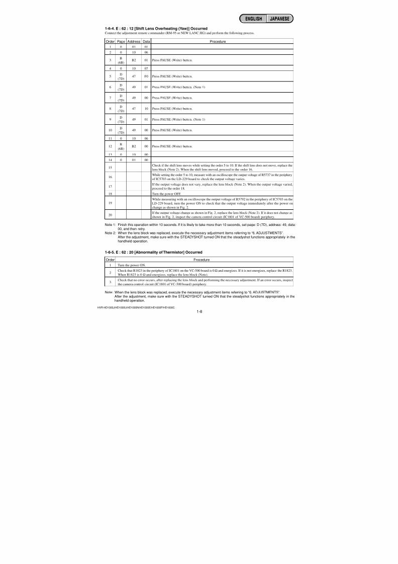
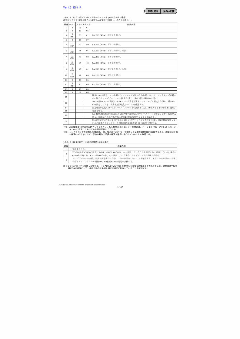
1-6-4. E : 62 : 12 [Shift Lens Overheating (Yaw)] OccurredConnect the adjustment remote commander (RM-95 or NEW LANC JIG) and perform the following process.
Order Page Address Data Procedure
1 0 01 01
2 0 10 06
3B
B2 01 Press PAUSE (Write) button.(6B)
4 0 10 07
5D
47 F0 Press PAUSE (Write) button.(7D)
6D
49 01 Press PAUSE (Write) button. (Note 1)(7D)
7D
49 00 Press PAUSE (Write) button.(7D)
8D
47 10 Press PAUSE (Write) button.
(7D)
9D
49 01 Press PAUSE (Write) button. (Note 1)(7D)
10D
49 00 Press PAUSE (Write) button.(7D)
11 0 10 06
12B
B2 00 Press PAUSE (Write) button.(6B)
13 0 10 00
14 0 01 00
15
Check if the shift lens moves while setting the order 5 to 10. If the shift lens does not move, replace the
lens block (Note 2). When the shift lens moved, proceed to the order 16.
16While setting the order 5 to 10, measure with an oscilloscope the output voltage of R5737 in the periphery
of IC5703 on the LD-229 board to check the output voltage varies.
17If the output voltage does not vary, replace the lens block (Note 2). When the output voltage varied,
proceed to the order 18.
18 Turn the power OFF.
19While measuring with an oscilloscope the output voltage of R5792 in the periphery of IC5703 on the
LD-229 board, turn the power ON to check that the output voltage immediately after the power on
change as shown in Fig. 2.
20If the output voltage change as shown in Fig. 2, replace the lens block (Note 2). If it does not change as
shown in Fig. 2, inspect the camera control circuit (IC1801 of VC-500 board) periphery.
Note 1: Finish this operation within 10 seconds. If it is likely to take more than 10 seconds, set page: D (7D), address: 49, data:00, and then retry.
Note 2: When the lens block was replaced, execute the necessary adjustment items referring to “6. ADJUSTMENTS”.After the adjustment, make sure with the STEADYSHOT turned ON that the steadyshot functions appropriately in thehandheld operation.
1-6-5. E : 62 : 20 [Abnormality of Thermistor] Occurred
Order Procedure
1 Turn the power ON.
2Check that R1823 in the periphery of IC1801 on the VC-500 board is 0 Ω and energizes. If it is not energizes, replace the R1823.
When R1823 is 0 Ω and energizes, replace the lens block (Note).
3 Check that no error occurs, after replacing the lens block and performing the necessary adjustment. If an error occurs, inspectthe camera control circuit (IC1801 of VC-500 board) periphery.
Note: When the lens block was replaced, execute the necessary adjustment items referring to “6. ADJUSTMENTS”.After the adjustment, make sure with the STEADYSHOT turned ON that the steadyshot functions appropriately in thehandheld operation.
7/18/2019 SONY+HVR-HD1000 SERVICE MANUAL
http://slidepdf.com/reader/full/sonyhvr-hd1000-service-manual 16/4251-9
ENGLISH JAPANESEENGLISH JAPANESE
HVR-HD1000J/HD1000U/HD1000N/HD1000E/HD1000P/HD1000C
1. SERVICE NOTE
1
2
Ver. 1.3 2008.12
7/18/2019 SONY+HVR-HD1000 SERVICE MANUAL
http://slidepdf.com/reader/full/sonyhvr-hd1000-service-manual 17/4251-10
ENGLISH JAPANESEENGLISH JAPANESE
HVR-HD1000J/HD1000U/HD1000N/HD1000E/HD1000P/HD1000C
1 13 1C
C : 3 1 : 1 1
C N 8 0 0 1
( S I D E
B )
CN1012
FLexible Flat Cable (FFC-107)
FP-786 Flexible
C N 8 1 0 1
C N 8 0 0 3
1
8
1
8
VC-500 BOARD(SIDE A)
CPC-15
(J-6082-564-A)
(J-6082-521-A)
MS-379 BOARD(SIDE A)
US-014 BOARD(SIDE A)
CN8102
Ver. 1.3 2008.12
7/18/2019 SONY+HVR-HD1000 SERVICE MANUAL
http://slidepdf.com/reader/full/sonyhvr-hd1000-service-manual 18/4251-11
ENGLISH JAPANESEENGLISH JAPANESE
HVR-HD1000J/HD1000U/HD1000N/HD1000E/HD1000P/HD1000C
C
C
C
C
C
C
C
C
C
C
C
C
C
C
C
C
C
C
C
C
C
C
C
C
C
C
C
C
C
C
0 4
2 1
2 2
3 1
3 1
3 1
3 1
3 1
3 1
3 1
3 1
3 1
3 1
3 1
3 1
3 1
3 2
3 2
3 2
3 2
3 2
3 2
3 2
3 2
3 2
3 2
3 2
3 2
3 2
3 2
0 0
0 0
0 0
1 0
1 1
2 0
2 1
2 2
2 3
3 0
3 1
4 0
4 1
4 2
4 3
4 4
1 0
1 1
2 0
2 1
2 2
2 3
3 0
3 1
4 0
4 1
4 2
4 3
4 4
6 0
qh qk
Ver. 1.3 2008.12
7/18/2019 SONY+HVR-HD1000 SERVICE MANUAL
http://slidepdf.com/reader/full/sonyhvr-hd1000-service-manual 19/4251-12
ENGLISH JAPANESEENGLISH JAPANESE
HVR-HD1000J/HD1000U/HD1000N/HD1000E/HD1000P/HD1000C
w; wa
Ver. 1.3 2008.12
7/18/2019 SONY+HVR-HD1000 SERVICE MANUAL
http://slidepdf.com/reader/full/sonyhvr-hd1000-service-manual 20/4251-13
ENGLISH JAPANESEENGLISH JAPANESE
HVR-HD1000J/HD1000U/HD1000N/HD1000E/HD1000P/HD1000C
R 5 7 9 2
IC5703
R 5 7 2 1
R 5 7 3 7
LD-229 BOARD (SIDE A)
IC1801R1823
I
C
R 8 3
VC-500 BOARD (SIDE A)
Ver. 1.3 2008.12
7/18/2019 SONY+HVR-HD1000 SERVICE MANUAL
http://slidepdf.com/reader/full/sonyhvr-hd1000-service-manual 21/4251-14
ENGLISH JAPANESEENGLISH JAPANESE
HVR-HD1000J/HD1000U/HD1000N/HD1000E/HD1000P/HD1000C
Ver. 1.3 2008.12
7/18/2019 SONY+HVR-HD1000 SERVICE MANUAL
http://slidepdf.com/reader/full/sonyhvr-hd1000-service-manual 22/4251-15
ENGLISH JAPANESEENGLISH JAPANESE
HVR-HD1000J/HD1000U/HD1000N/HD1000E/HD1000P/HD1000C
Ver. 1.3 2008.12
7/18/2019 SONY+HVR-HD1000 SERVICE MANUAL
http://slidepdf.com/reader/full/sonyhvr-hd1000-service-manual 23/4251-16E
ENGLISH JAPANESEENGLISH JAPANESE
HVR-HD1000J/HD1000U/HD1000N/HD1000E/HD1000P/HD1000C
Ω
Ω
Ver. 1.3 2008.12
7/18/2019 SONY+HVR-HD1000 SERVICE MANUAL
http://slidepdf.com/reader/full/sonyhvr-hd1000-service-manual 24/4252-1HVR-HD1000J/HD1000U/HD1000N/HD1000E/HD1000P/HD1000C
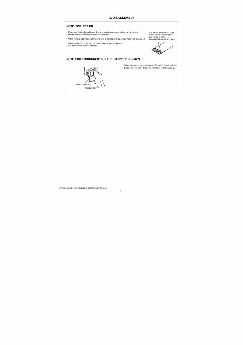
2. DISASSEMBLY
Cut and remove the part of gilt
which comes off at the point.(Be careful or somepieces of gilt may be left inside)
NOTE FOR REPAIR
• Make sure that the flat cable and flexible board are not cracked of bent at the terminal.
Do not insert the cable insufficiently nor crookedly.
• When remove a connector, don’t pull at wire of connector. It is possible that a wire is snapped.
• When installing a connector, don’t press down at wire of connector.It is possible that a wire is snapped.
NOTE FOR DISCONNECTING THE HARNESS (HN-047)
When disconnecting the harness (HN-047), do not pull the
harness part but pull off the connector body with tweezers etc.
Harness (HN-047)
Tweezers etc.
7/18/2019 SONY+HVR-HD1000 SERVICE MANUAL
http://slidepdf.com/reader/full/sonyhvr-hd1000-service-manual 25/4252-2HVR-HD1000J/HD1000U/HD1000N/HD1000E/HD1000P/HD1000C
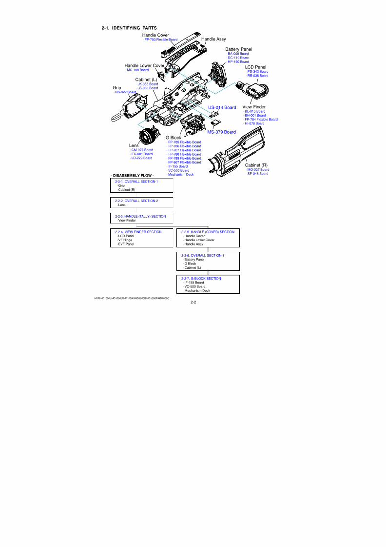
2-1. IDENTIFYING PARTS
Grip ⋅ NS-022 Board
Handle Cover ⋅ FP-793 Flexible Board
Handle Lower Cover ⋅ MC-188 Board
Handle Assy
Lens ⋅ CM-077 Board
⋅ EC-001 Board ⋅ LD-229 Board
View Finder ⋅ BL-015 Board ⋅ BH-001 Board ⋅ FP-784 Flexible Board ⋅ HI-078 Board
G Block ⋅ FP-785 Flexible Board ⋅ FP-786 Flexible Board ⋅ FP-787 Flexible Board ⋅ FP-788 Flexible Board ⋅ FP-789 Flexible Board ⋅
FP-867 Flexible Board ⋅ IF-155 Board ⋅ VC-500 Board ⋅ Mechanism Deck
Battery Panel
⋅ BA-008 Board ⋅ DC-110 Board ⋅ HP-150 Board
LCD Panel ⋅ PD-342 Board ⋅ RE-038 Board
Cabinet (R) ⋅ MO-027 Board ⋅ SP-048 Board
Cabinet (L) ⋅ JK-355 Board ⋅ JS-033 Board
MS-379 Board
US-014 Board
2-2-1. OVERALL SECTION-1 ⋅Grip
⋅Cabinet (R)
2-2-2. OVERALL SECTION-2
⋅Lens
2-2-4. VIEW FINDER SECTION ⋅LCD Panel ⋅VF Hinge
⋅EVF Panel
2-2-3. HANDLE (TALLY) SECTION ⋅View Finder
2-2-5. HANDLE (COVER) SECTION ⋅Handle Cover ⋅Handle Lower Cover
⋅Handle Assy
2-2-6. OVERALL SECTION-3 ⋅Battery Panel
⋅G Block ⋅Cabinet (L)
2-2-7. G BLOCK SECTION ⋅ IF-155 Board ⋅VC-500 Board
⋅Mechanism Deck
- DISASSEMBLY FLOW -
7/18/2019 SONY+HVR-HD1000 SERVICE MANUAL
http://slidepdf.com/reader/full/sonyhvr-hd1000-service-manual 26/4252-3HVR-HD1000J/HD1000U/HD1000N/HD1000E/HD1000P/HD1000C
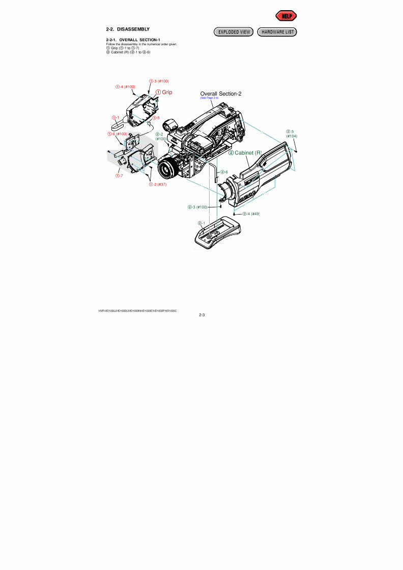
2-2. DISASSEMBLY
2-2-1. OVERALL SECTION-1Follow the disassembly in the numerical order given.
1 Grip (1-1 to1-7)2 Cabinet (R) (2-1 to2-6)
HELPHELP
EXPLODED VIEW HARDWARE LIST
2Cabinet (R)
1Grip
2-2(#100)
2-3 (#100)
2-4 (#49)
2-5(#104)
2-6
2-1
Overall Section-2(See Page 2-4)
1-2 (#37)
1-3 (#100)
1-4 (#100)
1-6 (#103)
1-7
1-51-1
7/18/2019 SONY+HVR-HD1000 SERVICE MANUAL
http://slidepdf.com/reader/full/sonyhvr-hd1000-service-manual 27/4252-4HVR-HD1000J/HD1000U/HD1000N/HD1000E/HD1000P/HD1000C
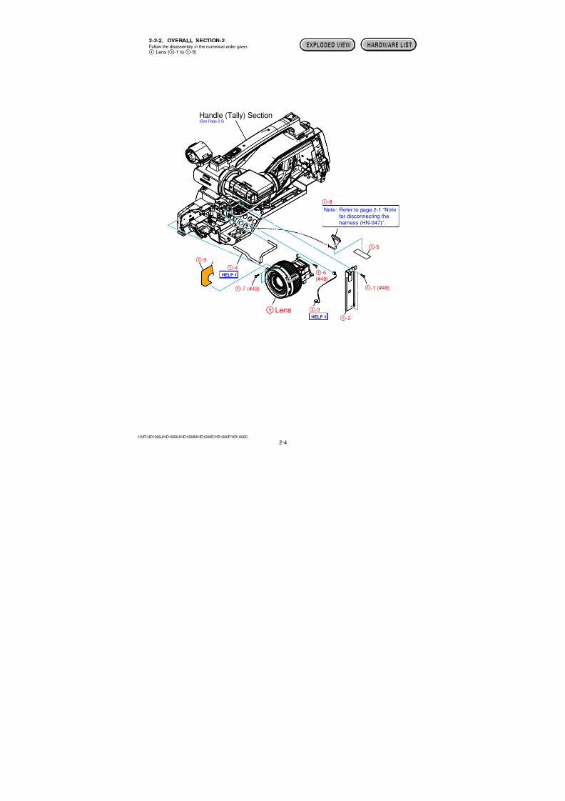
2-2-2. OVERALL SECTION-2Follow the disassembly in the numerical order given.
1 Lens (1-1 to1-9)
EXPLODED VIEW HARDWARE LIST
1Lens
Handle (Tally) Section(See Page 2-5)
1-1 (#49)1-7 (#49)
1-6(#49)
1-2
1-5
1-8
1-3
1-9
1-4
Note: Refer to page 2-1 “Notefor disconnecting theharness (HN-047)”.
HELP 1
HELP 1
7/18/2019 SONY+HVR-HD1000 SERVICE MANUAL
http://slidepdf.com/reader/full/sonyhvr-hd1000-service-manual 28/4252-5HVR-HD1000J/HD1000U/HD1000N/HD1000E/HD1000P/HD1000C
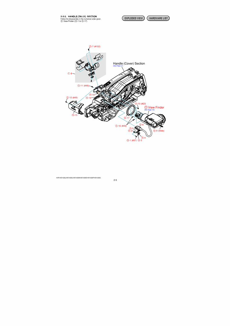
2-2-3. HANDLE (TALLY) SECTIONFollow the disassembly in the numerical order given.
1 View Finder (1-1 to1-17)
EXPLODED VIEW HARDWARE LIST
1View Finder(See Page 2-6)
Handle (Cover) Section(See Page 2-7)
1-1 (#37)
1-10 (#23)
1-11 (#49)
1-16 (#49)
1-17
1-12 (#49)
1-13
1-14
1-15
1-9 (Slide)
1-7 (#102)
1-8
1-2
1-31-4
1-5
1-6

7/18/2019 SONY+HVR-HD1000 SERVICE MANUAL
http://slidepdf.com/reader/full/sonyhvr-hd1000-service-manual 29/4252-6HVR-HD1000J/HD1000U/HD1000N/HD1000E/HD1000P/HD1000C
2-2-4. VIEW FINDER SECTIONFollow the disassembly in the numerical order given.
1 LCD Panel (1-1 to1-20)2 VF Hinge (2-1 to2-2)3 EVF Panel (3-1 to3-3)
EXPLODED VIEW HARDWARE LIST
2VF Hinge
1LCD Panel 2-1
(Rotate)
2-2 (#37)
1-1 (Rotate)
1-2 (#49)
1-4 (#37)
1-6 (#37)
1-7(#37)
1-10(#105)
1-17(#105)
1-11
1-14
1-15
1-16
1-121-13
1-8
1-18
1-20
1-19
1-9
1-5
1-3(#49)
HELP 2
3-2(#37)
3-1
3-3
3EVF Panel
7/18/2019 SONY+HVR-HD1000 SERVICE MANUAL
http://slidepdf.com/reader/full/sonyhvr-hd1000-service-manual 30/4252-7HVR-HD1000J/HD1000U/HD1000N/HD1000E/HD1000P/HD1000C
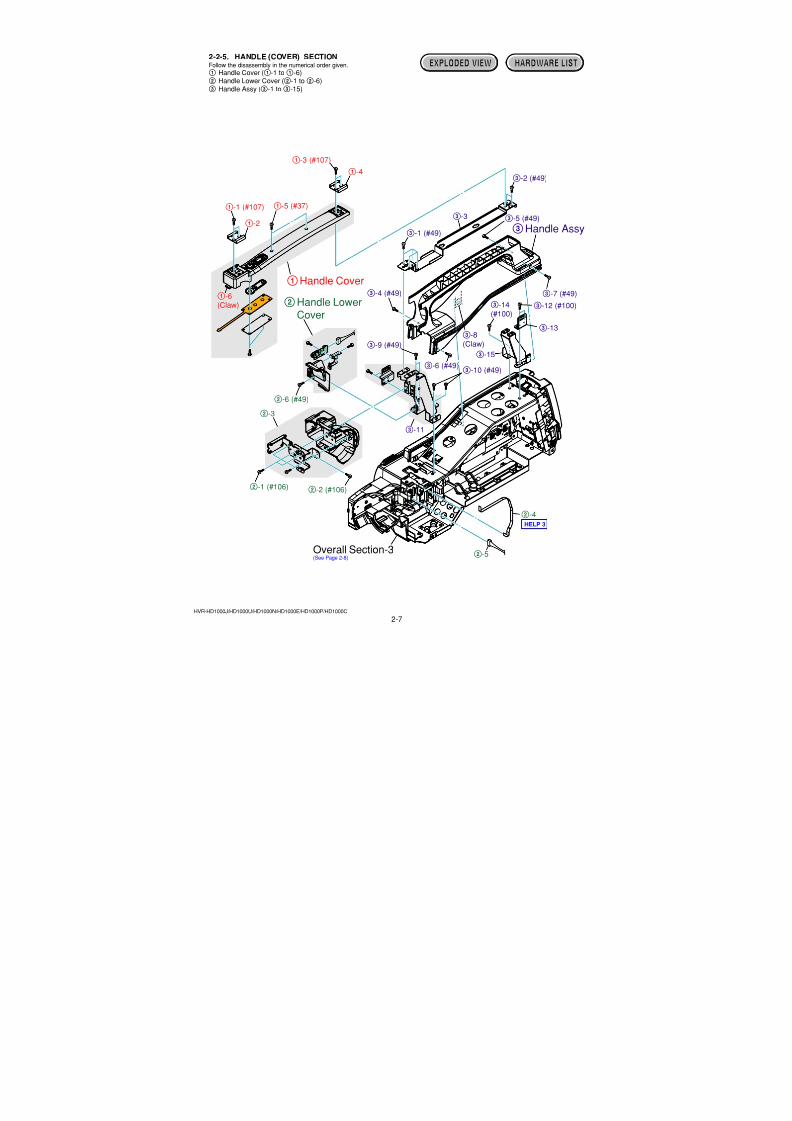
EXPLODED VIEW HARDWARE LIST2-2-5. HANDLE (COVER) SECTIONFollow the disassembly in the numerical order given.
1 Handle Cover (1-1 to1-6)2 Handle Lower Cover (2-1 to2-6)3 Handle Assy (3-1 to3-15)
2Handle LowerCover
1Handle Cover
2-1 (#106) 2-2 (#106)
2-6 (#49)
2-3
2-4
2-5
1-1 (#107)
1-3 (#107)
1-5 (#37)
1-6(Claw)
1-2
1-4
3-1 (#49)
3-6 (#49)
3-9 (#49)
3-10 (#49)
3-12 (#100)3-14(#100)
3-13
3-15
3-11
3-4 (#49) 3-7 (#49)
3-8(Claw)
3-5 (#49)
3-2 (#49)
3-3
Overall Section-3(See Page 2-8)
3Handle Assy
HELP 3
7/18/2019 SONY+HVR-HD1000 SERVICE MANUAL
http://slidepdf.com/reader/full/sonyhvr-hd1000-service-manual 31/4252-8HVR-HD1000J/HD1000U/HD1000N/HD1000E/HD1000P/HD1000C
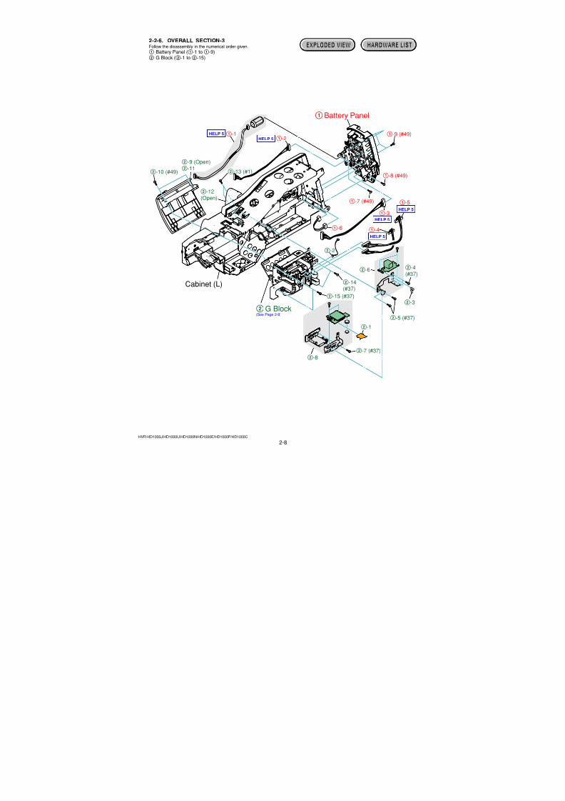
EXPLODED VIEW HARDWARE LIST2-2-6. OVERALL SECTION-3Follow the disassembly in the numerical order given.
1 Battery Panel (1-1 to1-9)2 G Block (2-1 to2-15)
HELP 5
HELP 5HELP 5
HELP 5
HELP 5
Cabinet (L)
2G Block(See Page 2-9)
1Battery Panel
2-4(#37)
2-14(#37)
2-15 (#37)
2-5 (#37)
2-7 (#37)
2-10 (#49) 2-13 (#1)
2-9 (Open)2-11
2-12(Open)
2-1
2-8
2-2
2-3
2-6
1-7 (#49)
1-8 (#49)
1-9 (#49)1-11-2
1-3
1-4
1-5
1-6
7/18/2019 SONY+HVR-HD1000 SERVICE MANUAL
http://slidepdf.com/reader/full/sonyhvr-hd1000-service-manual 32/4252-9EHVR-HD1000J/HD1000U/HD1000N/HD1000E/HD1000P/HD1000C
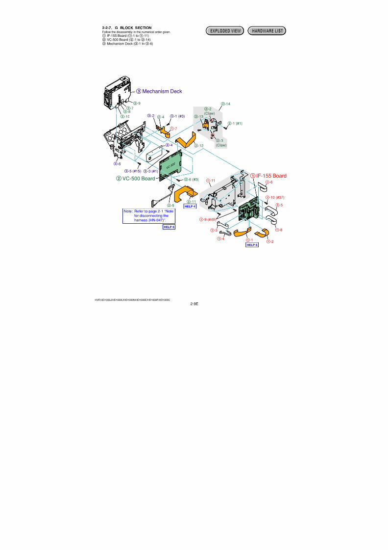
EXPLODED VIEW HARDWARE LIST2-2-7. G BLOCK SECTIONFollow the disassembly in the numerical order given.
1 IF-155 Board (1-1 to1-11)2 VC-500 Board (2-1 to2-14)3 Mechanism Deck (3-1 to3-6)
VC-500
2VC-500 Board 1 IF-155 Board
2-1 (#1)
2-6 (#3)
2-3(Claw)
2-2(Claw)
2-13
2-14
2-4
2-72-8
2-10
2-11
2-12
2-9
2-5
1-9 (#49)
1-11
1-10 (#37)
1-1 1-2
1-6
1-7
1-3 1-8
1-4
1-5
3-1 (#3)
3-3 (#1)3-5 (#15)
3-2
3-4
3-6
3Mechanism Deck
Note: Refer to page 2-1 “Notefor disconnecting the
harness (HN-047)”.
HELP 4
HELP 6
HELP 6
7/18/2019 SONY+HVR-HD1000 SERVICE MANUAL
http://slidepdf.com/reader/full/sonyhvr-hd1000-service-manual 33/425HELP
HVR-HD1000J/HD1000U/HD1000N/HD1000E/HD1000P/HD1000C
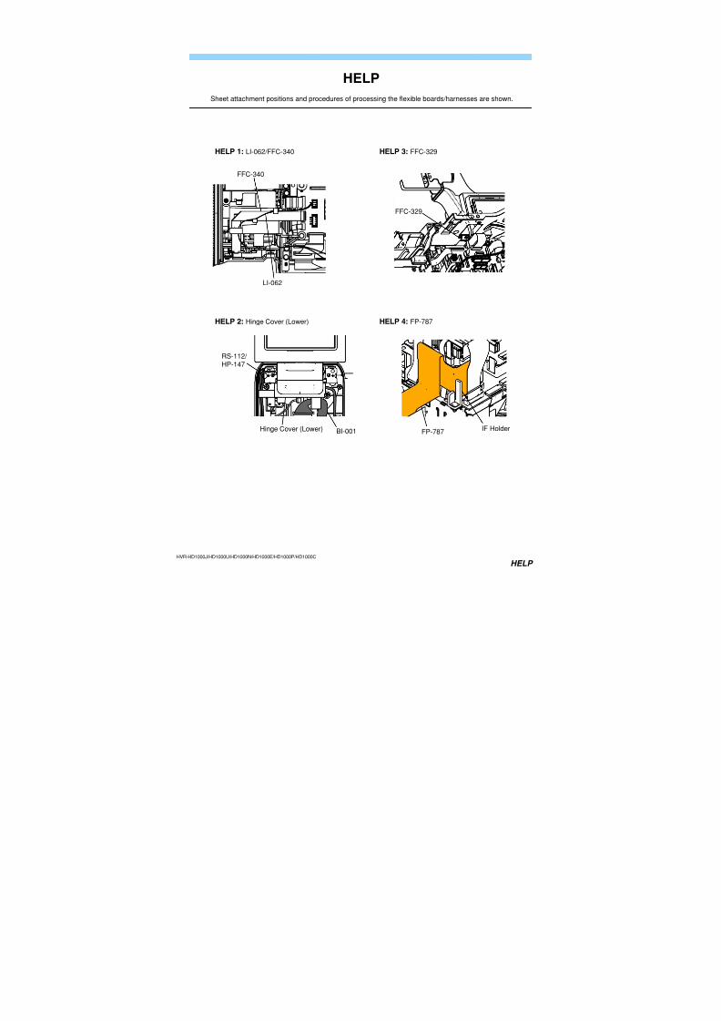
HELP
Sheet attachment positions and procedures of processing the flexible boards/harnesses are shown.
HELP 1: LI-062/FFC-340
LI-062
FFC-340
HELP 2: Hinge Cover (Lower)
Hinge Cover (Lower)
RS-112/ HP-147
BI-001
HELP 3: FFC-329
FFC-329
HELP 4: FP-787
FP-787 IF Holder
7/18/2019 SONY+HVR-HD1000 SERVICE MANUAL
http://slidepdf.com/reader/full/sonyhvr-hd1000-service-manual 34/425HELP
HVR-HD1000J/HD1000U/HD1000N/HD1000E/HD1000P/HD1000C
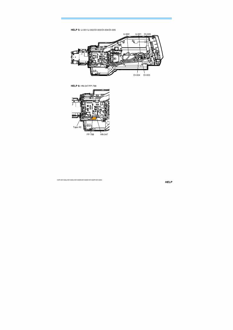
HELP 5: IJ-001/IJ-002/DI-003/DI-004/DI-005
HELP 6: HN-047/FP-788
HN-047FP-788
Tape AS
IJ-001IJ-002
DI-003
DI-005
DI-004
7/18/2019 SONY+HVR-HD1000 SERVICE MANUAL
http://slidepdf.com/reader/full/sonyhvr-hd1000-service-manual 35/425
HVR-HD1000J/HD1000U/HD1000N/HD1000E/HD1000P/HD1000C
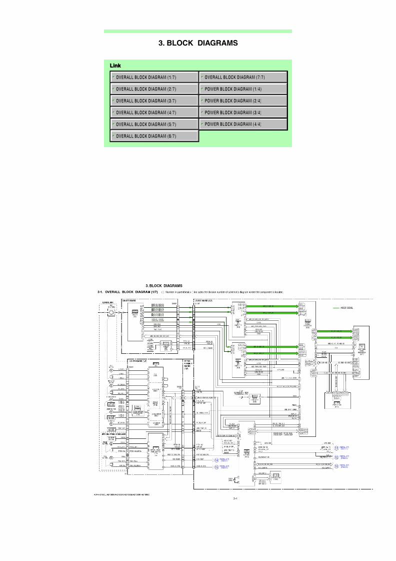
Link Link
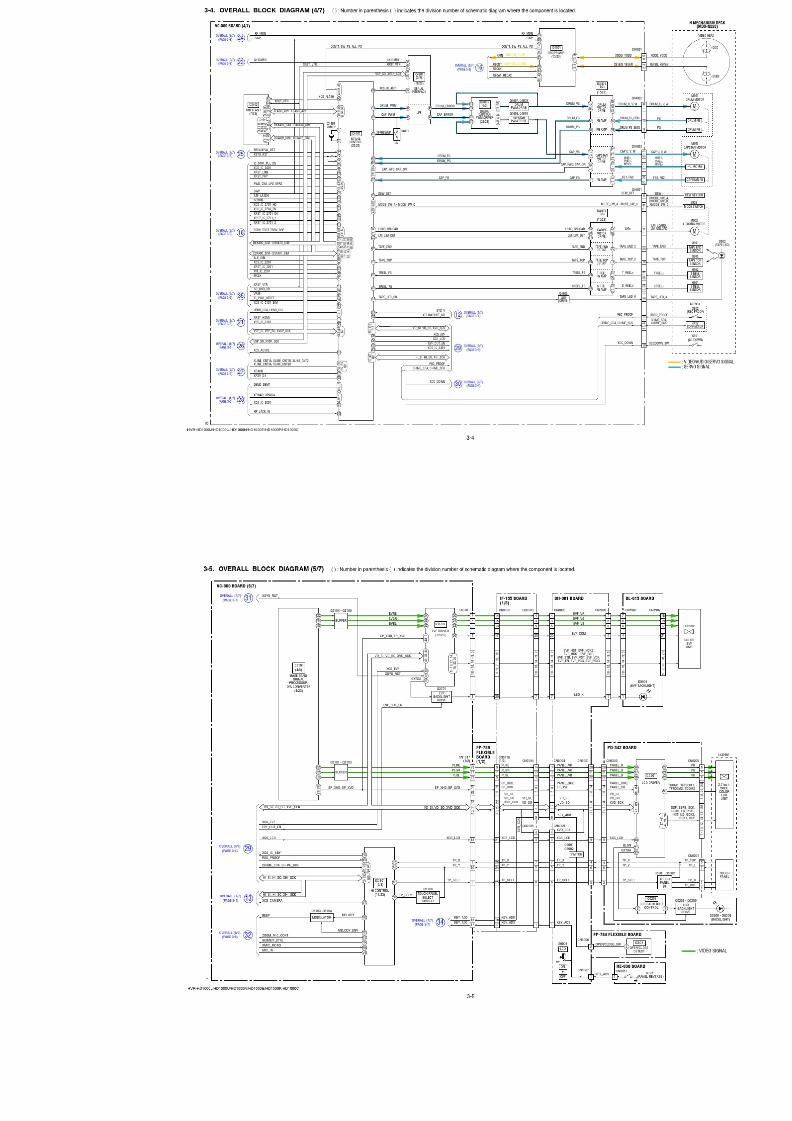
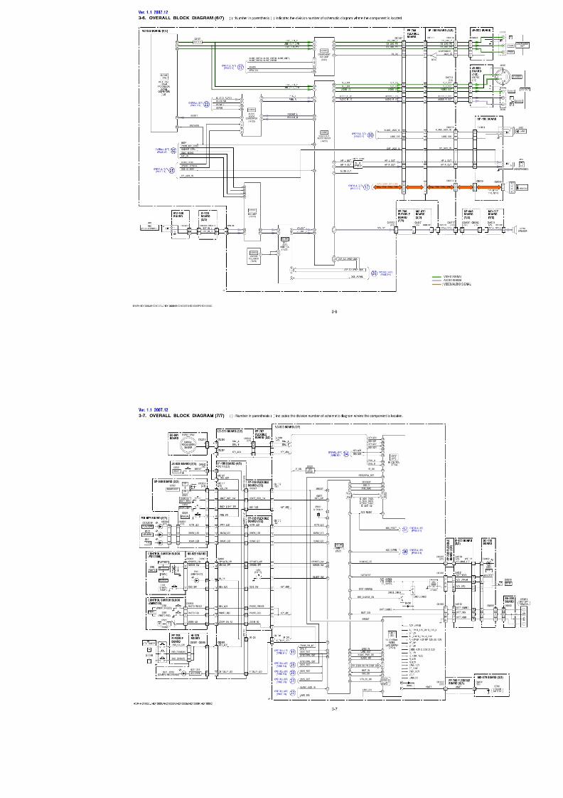
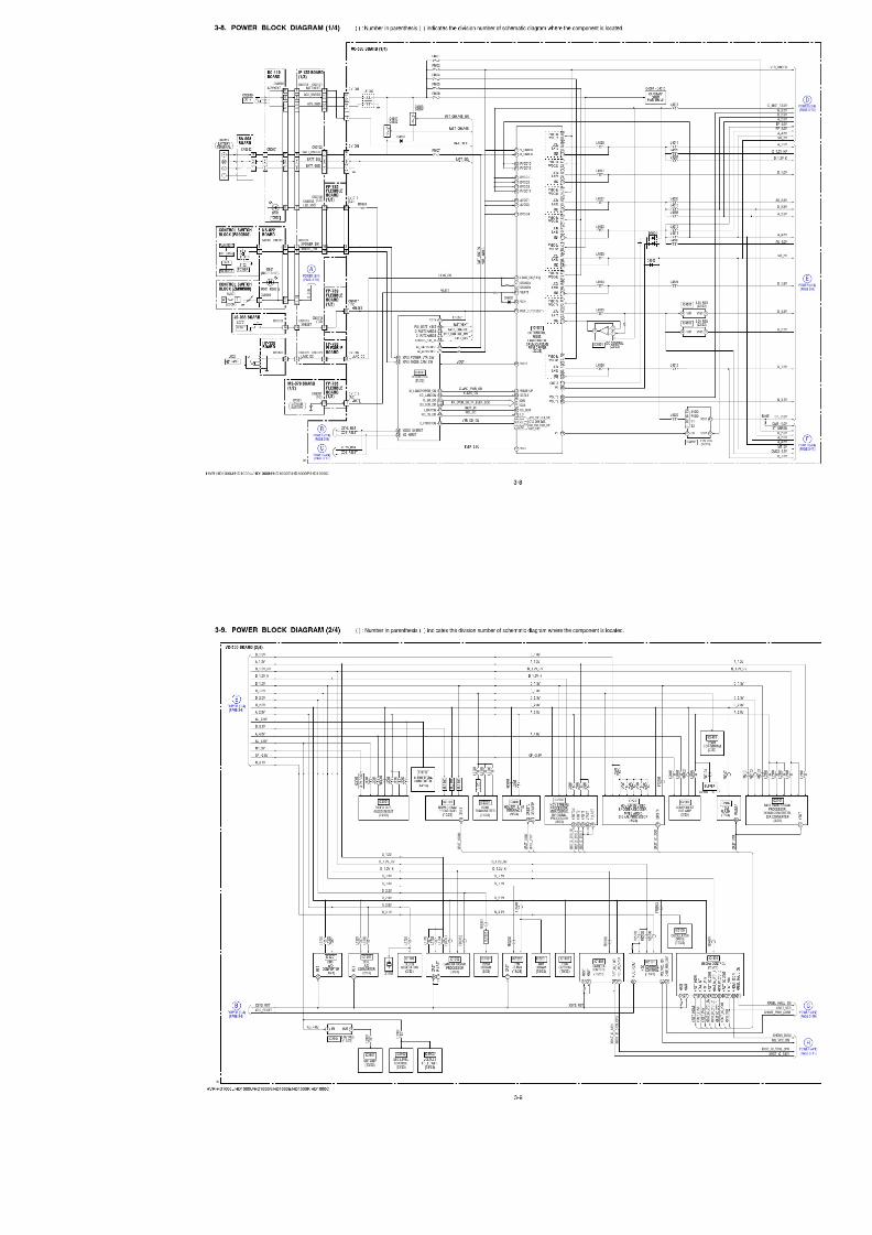
3. BLOCK DIAGRAMS
OVERALL BLOCK DIAGRAM (5/7)
OVERALL BLOCK DIAGRAM (6/7)
OVERALL BLOCK DIAGRAM (4/7)
OVERALL BLOCK DIAGRAM (3/7)
OVERALL BLOCK DIAGRAM (2/7)
OVERALL BLOCK DIAGRAM (1/7)
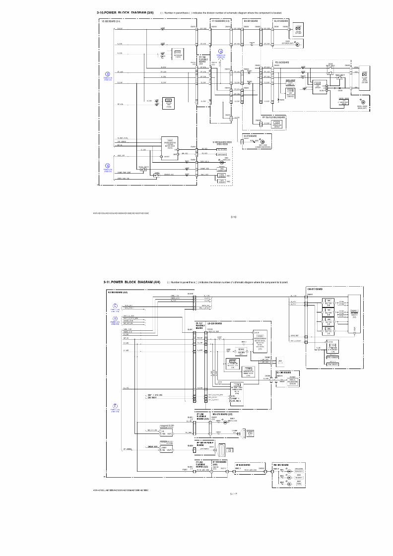
POWER BLOCK DIAGRAM (3/4)
POWER BLOCK DIAGRAM (4/4)
POWER BLOCK DIAGRAM (2/4)
POWER BLOCK DIAGRAM (1/4)
OVERALL BLOCK DIAGRAM (7/7)
7/18/2019 SONY+HVR-HD1000 SERVICE MANUAL
http://slidepdf.com/reader/full/sonyhvr-hd1000-service-manual 36/425
7/18/2019 SONY+HVR-HD1000 SERVICE MANUAL
http://slidepdf.com/reader/full/sonyhvr-hd1000-service-manual 37/425
7/18/2019 SONY+HVR-HD1000 SERVICE MANUAL
http://slidepdf.com/reader/full/sonyhvr-hd1000-service-manual 38/425
7/18/2019 SONY+HVR-HD1000 SERVICE MANUAL
http://slidepdf.com/reader/full/sonyhvr-hd1000-service-manual 39/425
7/18/2019 SONY+HVR-HD1000 SERVICE MANUAL
http://slidepdf.com/reader/full/sonyhvr-hd1000-service-manual 40/425
7/18/2019 SONY+HVR-HD1000 SERVICE MANUAL
http://slidepdf.com/reader/full/sonyhvr-hd1000-service-manual 41/425
7/18/2019 SONY+HVR-HD1000 SERVICE MANUAL
http://slidepdf.com/reader/full/sonyhvr-hd1000-service-manual 42/425
7/18/2019 SONY+HVR-HD1000 SERVICE MANUAL
http://slidepdf.com/reader/full/sonyhvr-hd1000-service-manual 43/425
7/18/2019 SONY+HVR-HD1000 SERVICE MANUAL
http://slidepdf.com/reader/full/sonyhvr-hd1000-service-manual 44/425
7/18/2019 SONY+HVR-HD1000 SERVICE MANUAL
http://slidepdf.com/reader/full/sonyhvr-hd1000-service-manual 45/425
3-10
HVR-HD1000J/HD1000U/HD1000N/HD1000E/HD1000P/HD1000C
3-10.POWER BLOCK DIAGRAM (3/4) ( ) : Number in parenthesis ( ) indicates the division number of schematic diagram where the component is located.
LCDBACKLIGHTCONTROL
VC-500 BOARD (3/4)
POWER (1/4)(PAGE 3-8)
D
POWER (2/4)(PAGE 3-9)
G
POWER (1/4)(PAGE 3-8)
A
PD-342 BOARD
FP-784 FLEXIBLE BOARD
FP-789FLEXIBLEBOARD(2/2)
CN6202
CN6004
CN0118(2/2)
CN6005
CN0104
CN0105
CN6006
CN6001
05
BL-015 BOARDBH-001 BOARD
2
CN5902
20
CN3701
2
CN5901CN6002CN6003
2
20EVF_VDD
EP_4.6V
EVF_VDD
EP_4.6V
N_8.5V
A_2.8V
A_4.6V
COLOREVF UNIT
D5901(EVF BACKLIGHT)
LCD902
EVF DRIVER(12/23)
IC3701
IC6202
OPEN/CLOSEDETECT
IC801
Q6201, Q6202
2 ,
3
CN1017(2/2)
22
6 ,
7
4 ,
5
D_2.8V
D_
2 . 8
V
D_2.8V
N_8.5V
A_2.8V
EP_4.6V
D_2.8VD_2.8V
EP_2.8V
A_4.6VA_4.6V
A_4.6V
EP_8.5V
EP_8.5V
EP_2.8V
EP_4.6VEP_4.6V
EVF_VDD
EP_4.6V
D_2.8V
A_4.6V
EP_8.5V
EP_2.8V
EP_4.6VEP_4.6V
TOUCHPANEL I/F
1
16
2
3
15
FB3701
FB6201
L3703
L3702
L3701
L6201
R6206
L6203
L6202
20
CN4801
12
26
21
CN4803
8
2 5 ,
2 6
DRUM/CAPSTAN/ LOADING
MOTOR DRIVE(16/23)
IC4801
SENSOR_VCC
17VH
MR_VCC3VMR
Q4802
CHIME_VDD
XREEL_HALL_ON
HE_VCC
HALL_VCC
FG_VCC
TAPE_LED_A
HU, HV, HW
CAPSTAN FG
MIC903
4PINCONNECTOR
D902(TAPE LED)
H901S REEL
SENSOR
H902T REEL
SENSOR
N MECHANISM DECK(MDX-N220)
L4801
R4812
R4801
34 XRESET
L4902
L4901 IC4901
REC/PBAMP
(15/23)
A_2.8V
MT_5V
VTR_UNREG
IC_4601_13.5V
D_2.8V
XRST_VTR
RP_4.6V
Q5110 - Q5112
CHIME_PWR_CONT
10
10
8
1
16
2
15
3
20
2
7 ,
8
19
8
D_2.8V
9
10
10
8
7 ,
8
9
12
14
FB6003
FB6001
FB6002
IF-155 BOARD (2/3)
CN0103CN0102
19
8
3 1 ,
3 2
2 7 ,
2 8
3 ,
4
2 9 ,
3 0
1
19
D201 - D203(CAMERA RECORDING)
CN0207
CN0101
HI-078 BOARD
R204 - R206
3 ,
4
5 ,
6
7/18/2019 SONY+HVR-HD1000 SERVICE MANUAL
http://slidepdf.com/reader/full/sonyhvr-hd1000-service-manual 46/425
7/18/2019 SONY+HVR-HD1000 SERVICE MANUAL
http://slidepdf.com/reader/full/sonyhvr-hd1000-service-manual 47/425
4-1
HVR-HD1000J/HD1000U/HD1000N/HD1000E/HD1000P/HD1000C
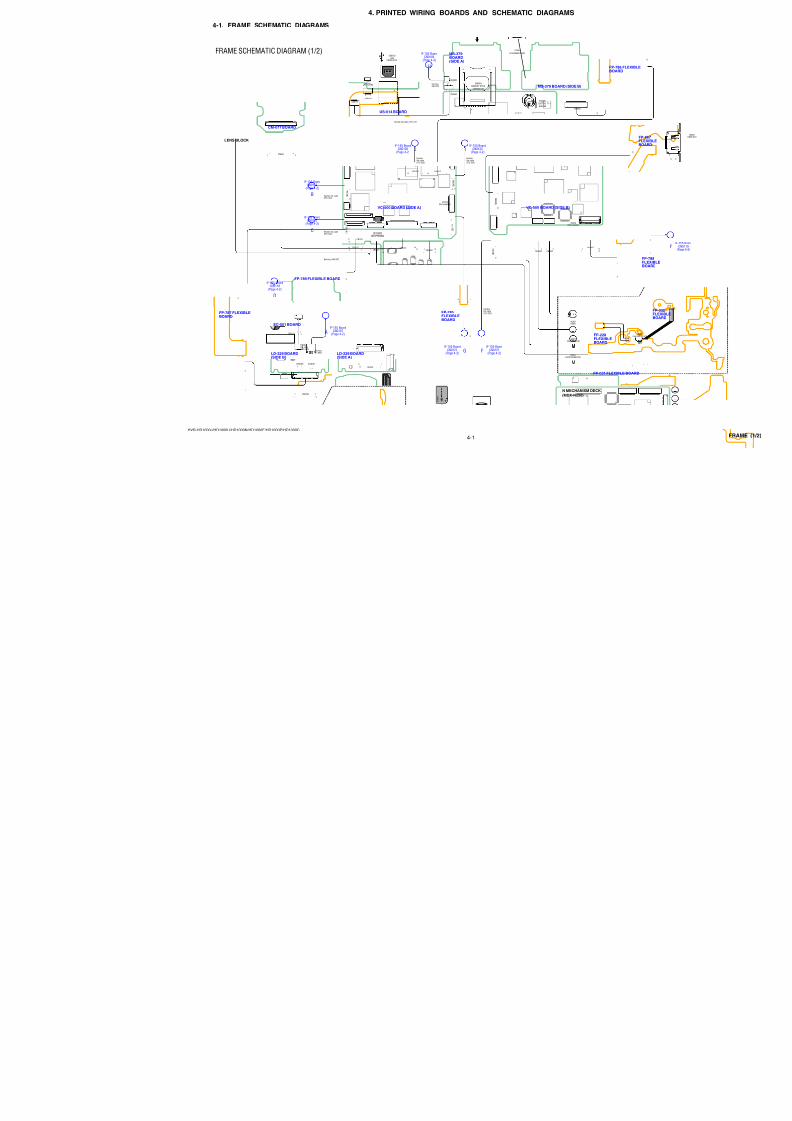
4-1. FRAME SCHEMATIC DIAGRAMS
4. PRINTED WIRING BOARDS AND SCHEMATIC DIAGRAMS
LD-229 BOARD(SIDE B)
LD-229 BOARD(SIDE A)
FP-787 FLEXIBLEBOARD
EC-001 BOARD
MS-379 BOARD (SIDE B)
MS-379BOARD(SIDE A)
US-014 BOARD
FP-789 FLEXIBLE BOARD
FP-785FLEXIBLEBOARD
FP-786BOAR
LENS BLOCK
BT901
LITHIUM BATTERY
MM
MM
B
C
JIF-155 Board
CN0102(Page 4-2)
IIF-155 Board
CN0122(Page 4-2)
D
A
IF-155 BoardCN0111
(Page 4-2)
IF-155 BoardCN0118
(Page 4-2)
IF-155 BoardCN0107
(Page 4-2)
IF-155 BoardCN0110
(Page 4-2)
GIF-155 Board
CN0120(Page 4-2)
Harness (HN-047)
Harness(LI-062)
H
IF-155 BoardCN0106
(Page 4-2)
Harness(MI-076)
FIF-155 Board
CN0121(Page 4-2)
VC-500 BOARD (SIDE A)
IC1802(EEPROM)
IC5202(Not supplied)
C N 1 0 0 3
1 2
1 6
C N 1 0 1 5
2 0
20
18
1
1
1
1 5
CN1012CN3701
Flexibleflat cable(FFC-330)
Flexible flat cable (FFC-107)
Flexible flat cable(FFC-334)
Flexible flat cable(FFC-335)
Flexibleflat cable(FFC-339)
Flexibleflat cable(FFC-332)
Flexibleflat cable(FFC-332)
11 2620
C N 1 0 0 6
1
1 4
C N 1 0 0 9
1
6
CN1017 1
1
33
33
1
33
232
CN1010 1
1
51
51
250
CN4801 282
291
CN1201 4014241
CN4803 262
271
CM-077 BOARD
CN6601 4014241
VC-500 BOARD (SIDE B)
IC2402(Not supplied)
C N 3 2 0 2
2 0
C N 1 0 0 1
1 6
1
CN48021 10
CN49011 10
CN1007
1
1
39
39
2 38
1
N MECHANISM DECK
(MDX-N220)
M903CAPSTAN MOTOR
M901DRUM MOTOR
VIDEOHEAD
29
1
FP-228FLEXIBLEBOARD
FP-031 FLEXIBL
CN5306 CN5307
CN5303
CN530116
2 1
2 50
1
1
51
51
50
51
2
1
CN5311 2 6
1 5
CN8002
CN8003
CN8004
MEMORY STICK
CONNECTOR
CN8001
BT901
BH8001
BATTERYHOLDER
2
1
17
8
110
12 11
2
1
1
26
26
CN8102
CN8101
1 8
18
CN8103USB
CONNECTOR
CPC
(For Check)
FRAME SCHEMATIC DIAGRAM (1/2)
7/18/2019 SONY+HVR-HD1000 SERVICE MANUAL
http://slidepdf.com/reader/full/sonyhvr-hd1000-service-manual 48/425
4-2
HVR-HD1000J/HD1000U/HD1000N/HD1000E/HD1000P/HD1000C
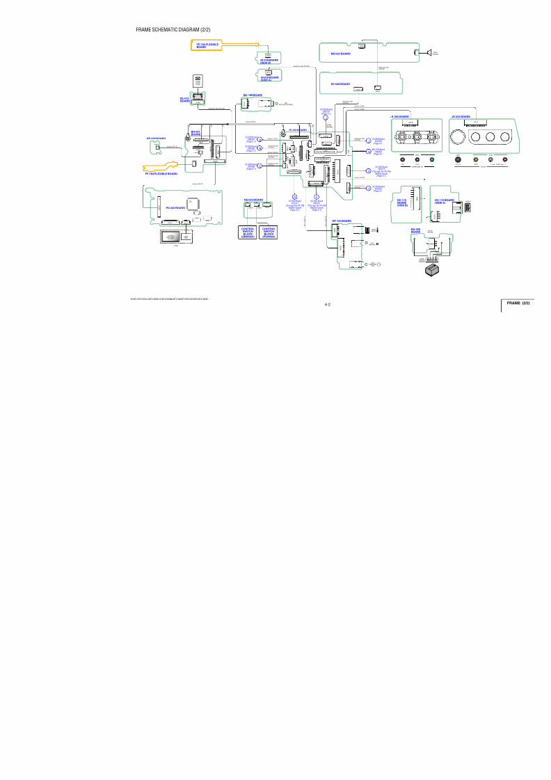
IF-155 BOARDBH-001BOARD
PD-342 BOARD
RE-038 BOARD
FP-784 FLEXIBLE BOARD
SP-048 BOARD
MO-027 BOARD
DC-110BOARD(SIDE B)
BA-008
BOARD
HP-150 BOARD
JK-355 BOARD
NS-022 BOARD
HI-078 BOARD(SIDE B)
HI-078 BOARD(SIDE A)
BL-015BOARD
MC-188 BOARD
FP-793 FLEXIBLEBOARD
CN0501CN0502
1
2
13
141
2 8
7
CN0504
CN0505
18
2
1
C N 0 6 0 2
1
9
CN0
SW
CN0651BATTERY
TERMINAL
C N 0 6 0 4
C N 0 6 0 3
1
1 0
1
6
Pr/Cr Pb/Cb Y
COPMPONENT OUT
CN0701
J0703
8 1
CN0901CN0902CN0903
12
1112
1
26
51
26
5
CN0201
CN0207
1
6
6
1
18
J401MIC (PLUG IN POWER)
C N 0 4 0 1
1
4
2.7 INCHWIDE COLOR
LCD UNIT
TOUCHPANEL
LCD901
LCD902COLOR
EVF UNIT
J652LANC JACK
J651HEADPHONE
JACK
CN0605HDV/DV
B
A
C
VC-500 BoardCN1006
(Page 4-1)
I
J
H
G
F
MS-379 BoardCN8002
(Page 4-1)
VC-500 BoardCN1003
(Page 4-1)
VC-500 BoardCN3701
(Page 4-1)
VC-500 BoardCN1001
(Page 4-1)
LD-229 BoardCN5307
(Page 4-1)
VC-500 BoardCN1009
(Page 4-1)
Harness (LI-062)
Harness (MI-075)
H a r n e s s
( D I - 0 0 5
)
Harnes
(BD-05
H a r n e s s
( D I - 0 0 4 )
Harness (MI-076)
Harness (IJ-002)
Harness (IJ-001)
Harness (DI-003)
Harness (BI-001)
Harness (RS-112)
Harness (HP-147)
CN0103
44 12 23 1 3
C N 0 1 0 4 C
N 0 1 0 7
C N 0 1 0 8
C N 0 1 0 9
C N 0 1 1 0
C N 0 1 1 1
C N 0 1 1 2CN0118
C N 0 1 0 1
C N 0 1 0 5
CN0102
CN0106
CN0113
CN0114
C N 0 1 1 5
C N 0 1 1 6
CN0117
CN0119
C N 0 1 2 0
C N 0 1 2 1
C N 0 1 2 2
1 5
1
2
1 2
1 1
1 2
1 2
1 3
1 4
2
6 5
2
7 8
1 20
1 1 1
4 1
1
2
33
1
1
2
19
20
1 0 2
1
1
6
112
1 8
1
1 0
1
9
1
2
32
2
1
38
39
1
1 7
1 8
1 2
1 5 1
6
1 2
1 5
13
14
2
1 6
CN6001
C N 6 0 0 2
CN6004
CN6005
CN6006
CN6007 C N 6 0 0 3
1 22
1 2
15 1
10
1 2
6 5
2
1
2 0
1 9 2
0
1
1
CN6201CN6205
C N 6 2 0 2
1
2 2
1 61 24
CN0851
1
2
1
6
DVC-500 Board
CN1017(Through the FP-789
flexible board)(Page 4-1)
EVC-500 Board
CN1007(Through the FP-788
flexible board)(Page 4-1)
VC-500 BoardCN1015
(Through the FP-785flexible board)
(Page 4-1)
Flexible flat cable(FFC-334)
Flexible flat cable (FFC-338)
Flexible flat cable(FFC-332)
Flexible flat cable(FFC-332)
Flexibleflat cable(FFC-330)
Flexible flat cable(FFC-337)
Flexible flat cable(FFC-336)
Flexible flat cable (FFC-329)
Flexible flat cable(FFC-335)
Flexible flat cable(FFC-340)
CONTROL
SWITCHBLOCK(PS90500)
CONTROL
SWITCHBLOCK(ZM90500)
CN5901
CN5902
1 20
1
2
21
20
FRAME SCHEMATIC DIAGRAM (2/2)
7/18/2019 SONY+HVR-HD1000 SERVICE MANUAL
http://slidepdf.com/reader/full/sonyhvr-hd1000-service-manual 49/425
HVR-HD1000J/HD1000U/HD1000N/HD1000E/HD1000P/HD1000C
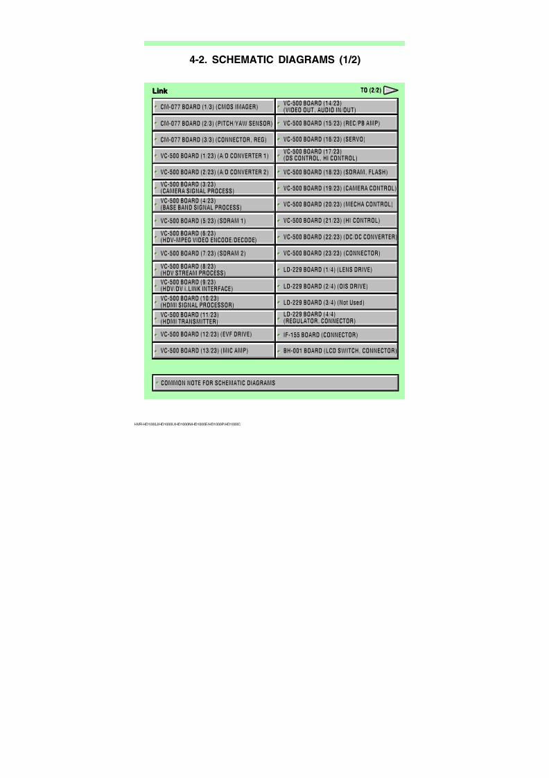
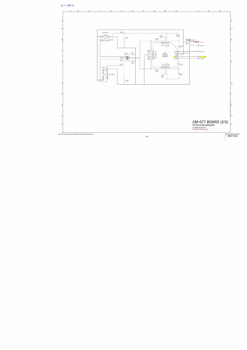
CM-077 BOARD (2/3) (PITCH/YAW SENSOR)
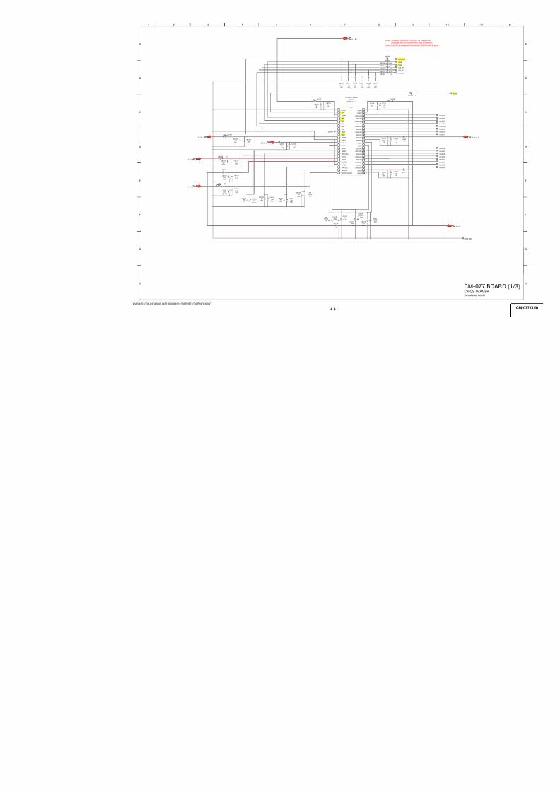
CM-077 BOARD (1/3) (CMOS IMAGER)
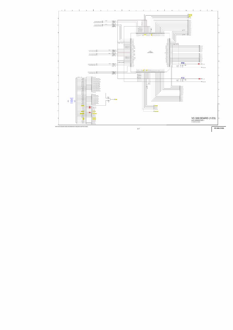
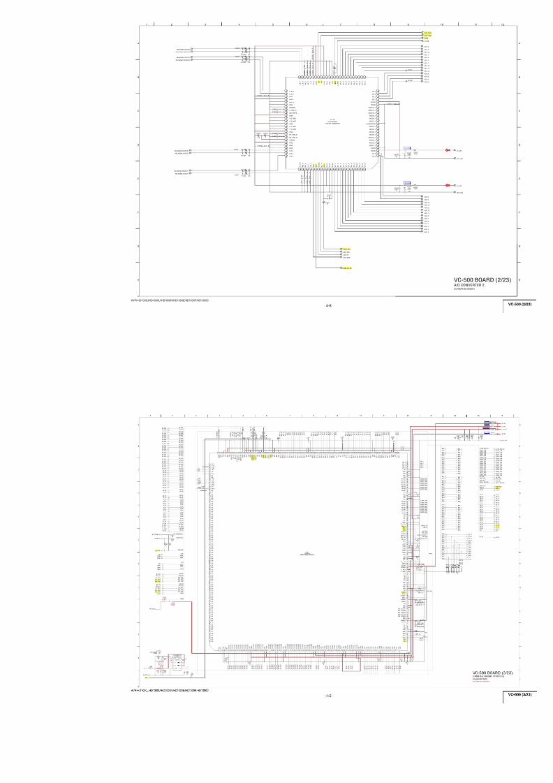
VC-500 BOARD (2/23) (A/D CONVERTER 2)
VC-500 BOARD (1/23) (A/D CONVERTER 1)
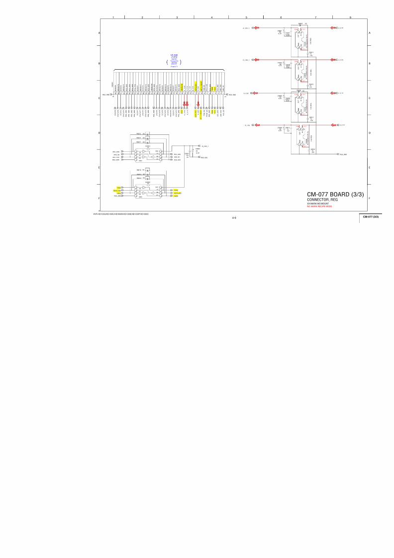
CM-077 BOARD (3/3) (CONNECTOR, REG)
VC-500 BOARD (18/23) (SDRAM, FLASH)
VC-500 BOARD (3/23)(CAMERA SIGNAL PROCESS) VC-500 BOARD (19/23) (CAMERA CONTROL)
VC-500 BOARD (20/23) (MECHA CONTROL)
VC-500 BOARD (21/23) (HI CONTROL)
VC-500 BOARD (22/23) (DC/DC CONVERTER)
VC-500 BOARD (23/23) (CONNECTOR)
VC-500 BOARD (14/23)(VIDEO OUT, AUDIO IN/OUT)
VC-500 BOARD (16/23) (SERVO)
VC-500 BOARD (15/23) (REC/PB AMP)
VC-500 BOARD (17/23)(DS CONTROL, HI CONTROL)
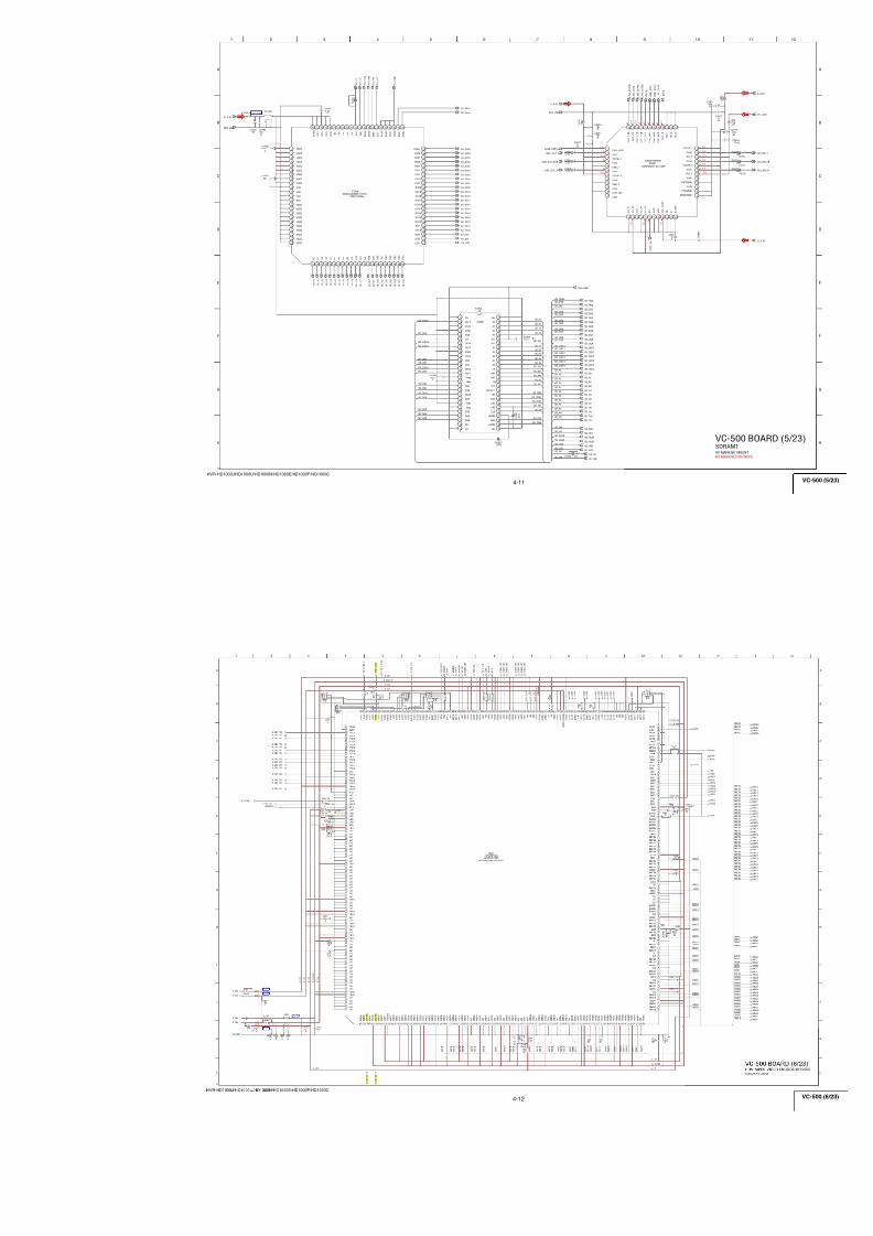
VC-500 BOARD (5/23) (SDRAM 1)
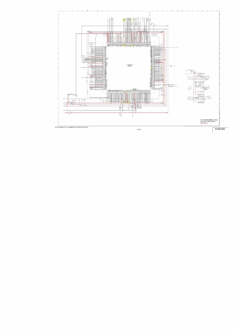
VC-500 BOARD (4/23)(BASE BAND SIGNAL PROCESS)
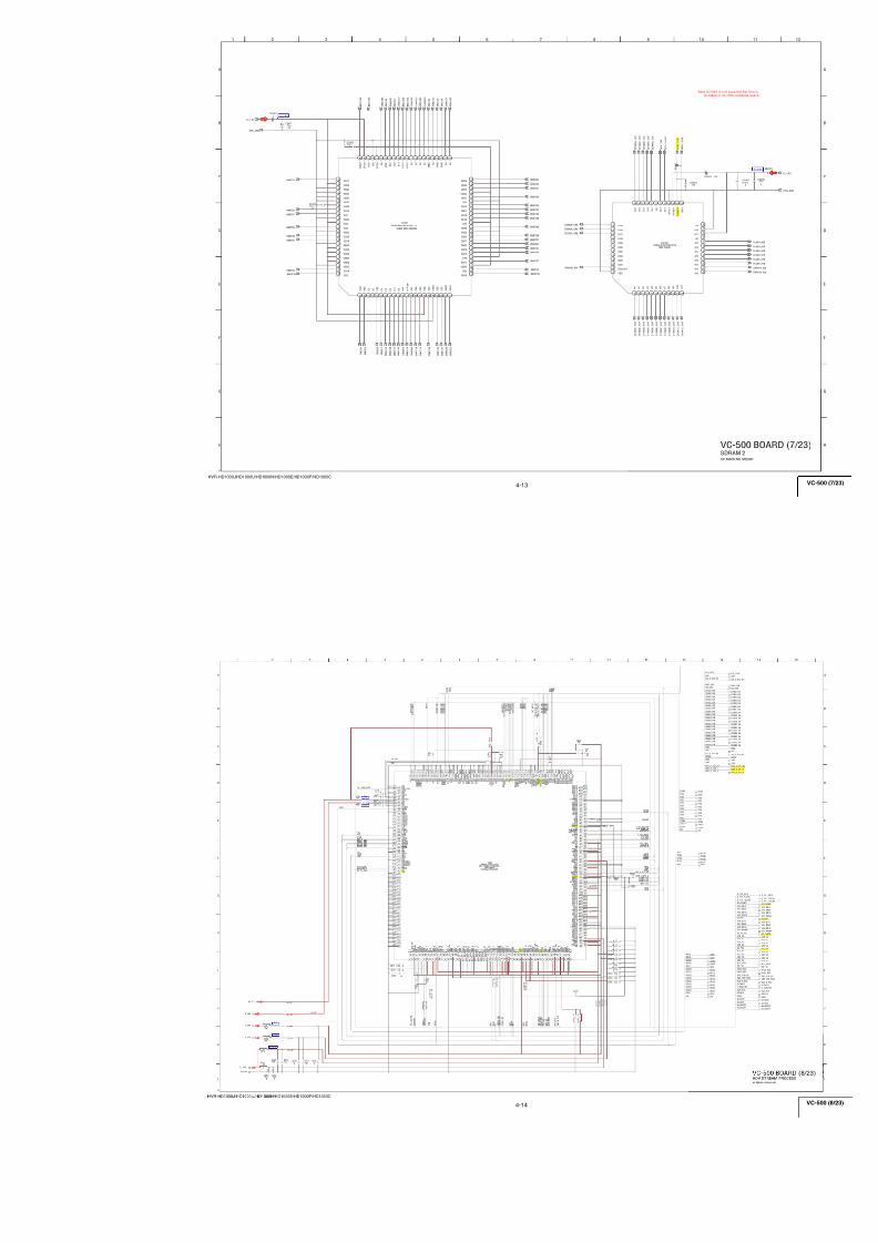
VC-500 BOARD (8/23)(HDV STREAM PROCESS)
VC-500 BOARD (6/23)(HDV-MPEG VIDEO ENCODE/DECODE)
VC-500 BOARD (7/23) (SDRAM 2)
LD-229 BOARD (1/4) (LENS DRIVE)
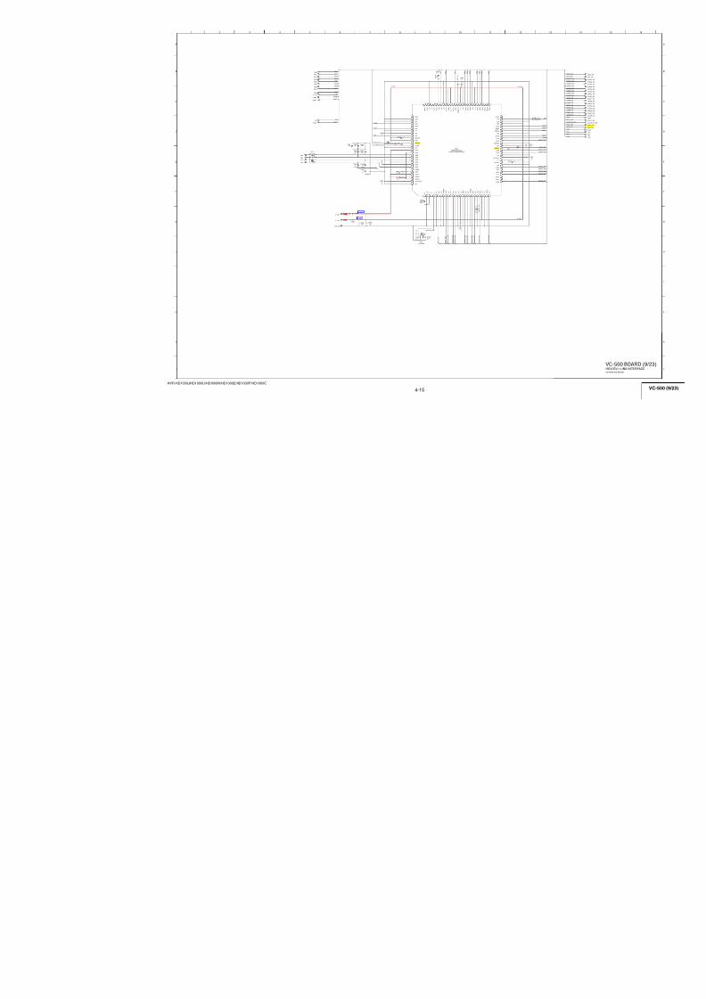
VC-500 BOARD (9/23)(HDV/DV i.LINK INTERFACE)
VC-500 BOARD (10/23)(HDMI SIGNAL PROCESSOR) LD-229 BOARD (3/4) (Not Used)
LD-229 BOARD (2/4) (OIS DRIVE)
VC-500 BOARD (11/23)(HDMI TRANSMITTER)
LD-229 BOARD (4/4)(REGULATOR, CONNECTOR)
VC-500 BOARD (12/23) (EVF DRIVE) IF-155 BOARD (CONNECTOR)
VC-500 BOARD (13/23) (MIC AMP) BH-001 BOARD (LCD SWITCH, CONNECTOR)
Link Link
COMMON NOTE FOR SCHEMATIC DIAGRAMS
TO (2/2)TO (2/2)
4-2. SCHEMATIC DIAGRAMS (1/2)
7/18/2019 SONY+HVR-HD1000 SERVICE MANUAL
http://slidepdf.com/reader/full/sonyhvr-hd1000-service-manual 50/425
HVR-HD1000J/HD1000U/HD1000N/HD1000E/HD1000P/HD1000C
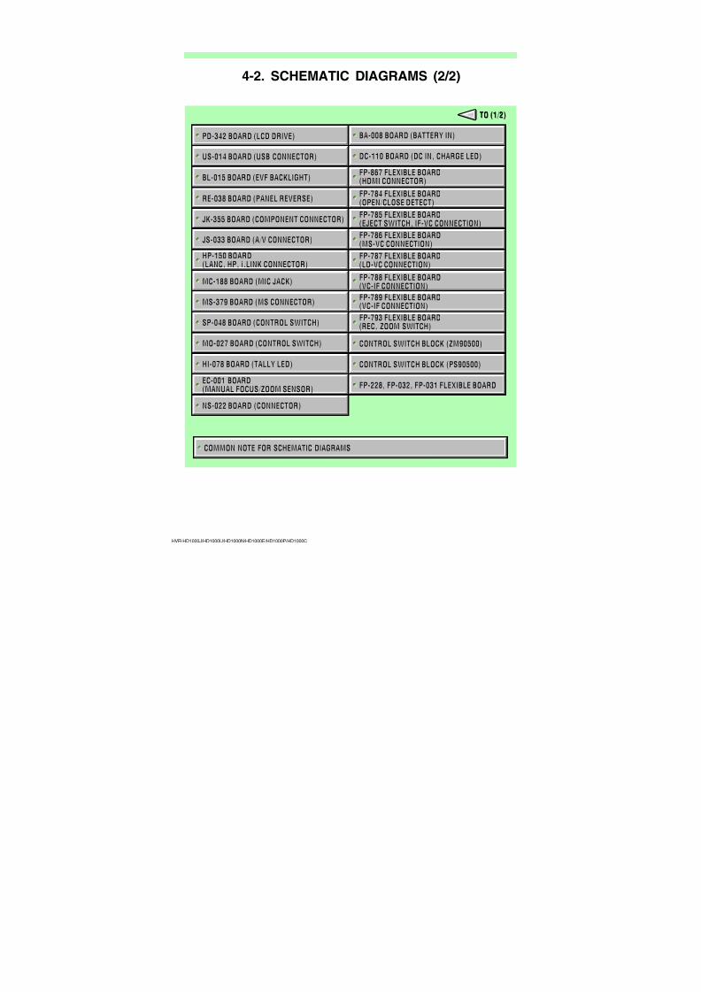
COMMON NOTE FOR SCHEMATIC DIAGRAMS
US-014 BOARD (USB CONNECTOR)
PD-342 BOARD (LCD DRIVE)
JK-355 BOARD (COMPONENT CONNECTOR)
RE-038 BOARD (PANEL REVERSE)
BL-015 BOARD (EVF BACKLIGHT)
FP-785 FLEXIBLE BOARD(EJECT SWITCH, IF-VC CONNECTION)
JS-033 BOARD (A/V CONNECTOR)FP-786 FLEXIBLE BOARD(MS-VC CONNECTION)
BA-008 BOARD (BATTERY IN)
DC-110 BOARD (DC IN, CHARGE LED)
FP-867 FLEXIBLE BOARD(HDMI CONNECTOR)
FP-784 FLEXIBLE BOARD(OPEN/CLOSE DETECT)
MC-188 BOARD (MIC JACK)
HP-150 BOARD(LANC, HP, i.LINK CONNECTOR)
MO-027 BOARD (CONTROL SWITCH)
MS-379 BOARD (MS CONNECTOR)
SP-048 BOARD (CONTROL SWITCH)
CONTROL SWITCH BLOCK (ZM90500)
HI-078 BOARD (TALLY LED) CONTROL SWITCH BLOCK (PS90500)
EC-001 BOARD(MANUAL FOCUS/ZOOM SENSOR)
NS-022 BOARD (CONNECTOR)
FP-228, FP-032, FP-031 FLEXIBLE BOARD
FP-787 FLEXIBLE BOARD(LD-VC CONNECTION)
FP-788 FLEXIBLE BOARD(VC-IF CONNECTION)
FP-789 FLEXIBLE BOARD(VC-IF CONNECTION)
FP-793 FLEXIBLE BOARD(REC, ZOOM SWITCH)
TO (1/2)TO (1/2)
4-2. SCHEMATIC DIAGRAMS (2/2)
7/18/2019 SONY+HVR-HD1000 SERVICE MANUAL
http://slidepdf.com/reader/full/sonyhvr-hd1000-service-manual 51/425
4-3
HVR-HD1000J/HD1000U/HD1000N/HD1000E/HD1000P/HD1000C
4-2. SCHEMATIC DIAGRAMS4-2. SCHEMATIC DIAGRAMS
(JAPANESE)
2
1
C
A
B
J
C
Ω
00
Pattern box PTB-450
J-6082-200-A
or
Small pattern box
PTB-1450
J-6082-557-A
For PTB-450:
J-6020-250-A
For PTB-1450:
J-6082-559-A
L = 1 m (PTB-450)L = 40 cm (PTB-1450)
L
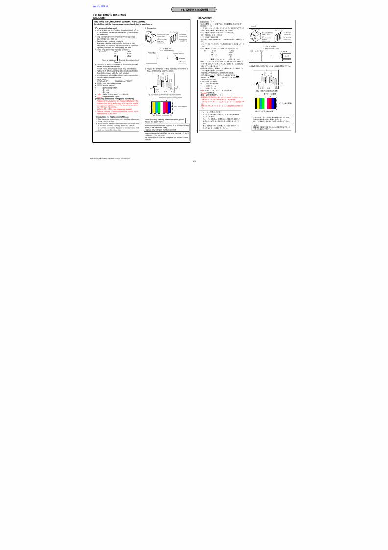
4-2. SCHEMATIC DIAGRAMS(ENGLISH)
1. Connection
2. Adjust the distance so that the output waveform ofFig. a and the Fig. b can be obtain.
When indicating parts by reference number, pleaseinclude the board name.
(For schematic diagrams)
• All capacitors are inµF unless otherwise noted. pF : µµF. 50 V or less are not indicated except for electrolyticsand tantalums.
• Chip resistors are 1/10 W unless otherwise noted.kΩ=1000Ω, MΩ=1000 kΩ.
• Caution when replacing chip parts.New parts must be attached after removal of chip.Be careful not to heat the minus side of tantalumcapacitor, Because it is damaged by the heat.
• Some chip part will be indicated as follows.Example C541 L452
22U 10UHTA A 2520
• Constants of resistors, capacitors, ICs and etc with XXindicate that they are not used.In such cases, the unused circuits may be indicated.
• Parts with differ according to the model/destination.Refer to the mount table for each function.
• All variable and adjustable resistors have characteristiccurve B, unless otherwise noted.
• Signal nameXEDIT→EDIT PB/XREC→ PB/REC
•2: non flammable resistor•5: fusible resistor•C: panel designation
•A: B+ Line•B: B– Line• J : IN/OUT direction of (+,–) B LINE.
•C: adjustment for repair.(Measuring conditions voltage and waveform)
• Voltages and waveforms are measured between themeasurement points and ground when camera shootscolor bar chart of patter n box. They are reference valuesand reference waveforms.
(VOM of DC 10 MΩ input impedance is used)• Voltage values change depending upon input
impedance of VOM used.)
Kinds of capacitorCase size
External dimensions (mm)
Y e l l o w
A AB BA=B
Fig. a (Video output terminal output waveform)
H
C y a n
G r e e n
W h i t e
M a g e n t a
R e d
B l u e
Fig.b (Picture on monitor TV)
CRT picture frame
Electronic beam scanning frame
THIS NOTE IS COMMON FOR SCHEMATIC DIAGRAMS
(In addition to this, the necessary note is printed in each block)
Pattern box
Pattern box PTB-450
J-6082-200-A
or
Small pattern box
PTB-1450
J-6082-557-A
Color bar chart
For PTB-450:
J-6020-250-A
For PTB-1450:
J-6082-559-A
Pattern box
Front of the lens
L = 1 m (PTB-450)L = 40 cm (PTB-1450)
L Camera
Precautions for Replacement of Imager
• If the imager has been replaced, carry out all the adjustments
for the camera section.
• As the imager may be damaged by static electricity from
its structure, handle it carefully like for the MOS IC.
In addition, ensure that the receiver is not covered with
dusts nor exposed to strong light.
The components identified by mark 0 or dotted line withmark0 are critical for safety.
Replace only with part number specified.
Les composants identifiés par une marque 0 sontcritiques pour la sécurité.Ne les remplacer que par une pièce por tant le numérospécifie.
Ver. 1.3 2008.12
7/18/2019 SONY+HVR-HD1000 SERVICE MANUAL
http://slidepdf.com/reader/full/sonyhvr-hd1000-service-manual 52/425
4-4
HVR-HD1000J/HD1000U/HD1000N/HD1000E/HD1000P/HD1000C
Note: Voltages of IC6701 can not be measured,because this is mounted by side of the lens.
Note: IC6701 is supplied including in CMOS block assy
3 6 9
B
7
C
8
D
G
E
H
1 4
A
2 5
F
C6718
0.1u
10V
C6740
0.1u10V
C67250.001u
50V
C6737XX
10V
C6714XX
10V
C6729
0.1u
10V
C6727
XX
50V
C6710XX10V
C6707
0.1u
10V
C6726XX
50V
C6723
XX
50V
C6722
XX
50V
C6704XX
10V
C6721
XX
50V
C6735XX
10V
C6728
XX10V
C6709
0.1u
10V
C6730
XX10V
C6702
XX10V
C6734
XX
10V
C6715XX
10V
C6716XX
10V
C6705
10u
6.3V
C6739
10u
6.3V
C6733
10u6.3V
C670610u
6.3V
C6701
XX6.3V
C6713XX
6.3V
C6724
10u6.3V
C6732
10u
6.3V
C673110u
6.3V
C6717
10u6.3V
C6736
10u6.3V
C6738
10u6.3V
CL6701
TGVD
AHS_SO
D_1.8V
A_3.3V_2
A_-1.0V
XSYS_RST
D_2.8V_1
D_1.8V
AHS_SCK
XCS_AHS
TGHD
1 DVSS1
2 INCK
3 DVDD1
4 XHS
5 XVS
6 SCK
7 SDI
8 XCE
9 TOUT
1 0 XCLR
1 1 IODVDD
1 2 AVSS1
1 3 AVDD1
1 4 VCLPE
1 5 VCLPP
1 6 LMOSG
1 7 VREFCASG
1
8
DVSS2 1 9 DVDD2
2 0 SUBVDD
2 1 PIXVSS
2 2 VREFSELL
2 3 VREFSUN
2 4 VCPOUT/VREFCP 2
5
2 6
2 7
2 8
2 9
3 0 3
1
3 2
3 3
3 4
3 5
3 6
3 7
3 8
3 9
4 0
4 1
4 2
4 3
4 4
4 5
4 6
4 7
4 8
R6705 XX
R6708 XX
R6704 XX
R6706 XX
R67030
R6707 XX
C6741XX
6.3V
C6742XX
6.3V
C6743
1u
10V
R6709 10
C671910u
6.3V
C6720
0.001u50V
C67082.2u10V
L6701XX
L6704 0
L67020
L6708 XX
L6709 XX
L6703XX
L6706
0
L6707
0
L6705
0
05
AVSS3
AVDD3
DRVOUT8
DCOUT8
DRVOUT7
DCOUT7DRVOUT6
DCOUT6
DRVOUT5
DCOUT5
VCLPP
VCLPE
IOAVSS1
IOAVDD2
DCOUT1
DRVOUT1
DCOUT2
DRVOUT2
DCOUT3
DRVOUT3
DCOUT4
DRVOUT4
AVDD2
AVSS2
IC6701
IMX022AHF-13
6M CMOS IMAGER
7/18/2019 SONY+HVR-HD1000 SERVICE MANUAL
http://slidepdf.com/reader/full/sonyhvr-hd1000-service-manual 53/425
4-5
HVR-HD1000J/HD1000U/HD1000N/HD1000E/HD1000P/HD1000C
A_2.8V
NO
1.3
1.52.8
1.4
2.8
1.2
D
C
6
B
A
53 4
F
2
E
1
C72010.1u
C72030.1u
FB7201
R720110k
C72070.047u
C72020.1u
R72031M
C7210
6.3V22u
C72060.047u
FB7204
R72021M
RB7201
C72114.7u
C72050.047u
L7210
IC7201
NJM3230SE7
12345
6
7
8
9
1 0
11 12 13 14 15
1 6
1 7
1 8
1 9
2 0
C72040.1u
1357
2468
R720410k
C72080.047u
FB7203
SE7201
4
12
3
C7209
6.3V22u
FB7202
SE7202
4 1
2 3Vcc
V c c
Vref
22k
O U T
YAW
OUT
V r e f
GND
H O 1
L O 1
H I 1
V R E F 1
A M 1
PITCH
G N D
PXX
PITCH/YAWSENSOR AMP
PITCH SENSOR
YAW SENSOR
C
GND
LIA1
LIB1
LIB2
LIA2
05
CRST
OUT2
OUT1
NC
V+
H O 2
V R E F 2
H I 2
L O 2
A M 2
Ver. 1.1 2007.12
7/18/2019 SONY+HVR-HD1000 SERVICE MANUAL
http://slidepdf.com/reader/full/sonyhvr-hd1000-service-manual 54/425
4-6
HVR-HD1000J/HD1000U/HD1000N/HD1000E/HD1000P/HD1000C
Harness(HN-047)
(Page 4-7)
Through the
VC-500
CN1201
(1/23)
NO
3.7
3.7
3.3
3.7
3.7
3.3
3.7
3.7
1.8
3.7
3.7
2.8
D
C
6
B
A
53 4
F
2
E
1
C66080.47u6.3V
C66070.47u6.3V
C66101u
10V
C66090.47u6.3V
C6601
XX
10V
C6602
XX
6.3V
C6605XX
6.3V
C6604XX
6.3V
C6603XX
6.3V
C6606XX
6.3V
D_2.8V_1
XSYS_RST
REG_GND
AHS_SO
REG_GND
REG_GND
A_3.3V
D_2.8V_1
AHS_SCK
TGVD
TGHD
D_1.8V
XCS_AHS
A_3.3V_2
R 1 1 1 4 Q 1 8 1 D - T
R - F
A
I C 6 6 0 6
12
3 4
R 1 1 1 4 Q 2 8 1 D - T
R - F
A
I C 6 6 0 4
12
3 4
R 1 1 1 4 Q 3 3 1 D - T
R - F
A
I C 6 6 0 3
12
3 4
R 1 1
1 4 Q 3 3 1 D - T
R - F
A
I C
6 6 0 5
12
3 4
IC6602XX
11A
23Y
32A
4GND
52Y
63A
71Y
8VCC
IC6601
XX
11A
23Y
32A
4GND
52Y
63A
71Y
8VCC
R6601 XX
R6604 XX
R6611 XX
R6612 XX
R6614 XX
R6615 XX
R6616 XX
R6613 XX
C N 6 6 0 1
1 2 3 4 5 6 7 8 9 1 0
1 1
1 2
1 3
1 4
1 5
1 6
1 7
1 8
1 9
2 0
2 1
2 2
2 3
2 4
2 5
2 6
2 7
2 8
2 9
3 0
3 1
3 2
3 3
3 4
3 5
3 6
3 7
3 8
3 9
4 0
C E
C E
I N
G N D
G N D
G N D
O U T
O U T
C E
G N D
C E
I N
CXX
C
O U T I N
O U T I N
D R V O U T 5
D C O U T 2
R E G
_ G N D
R E G
_ G N D
D R V O U T 1
T G H D
C H C K 2 / 4 M
D C O U T 3
D R V O U T 2
X C S
_ A H S
T G V D
A H S
_ S C K
D C O U T 4
D C O U T 5
D C O U T 6
D R V O U T 4
D R V O U T 6
D C O U T 1
A H S
_ S O
D R V O U T 3
R E G
_ G N D
A_
- 1 . 0
V
D_
2 . 8
V
A_
4 . 1
V
D_
1 . 5
V
X S Y S
_ R S T
D R V O U T 7
D C O U T 7
D C O U T 8
D R V O U T 8
P I T C H
_ A D
Y A W
_ A D
V S T
_ C
_ R E S E T
A_
2 . 8
V
R E G
_ G N D
R E G
_ G N D
R E G
_ G N D
R E G
_ G N D
C H C K 3 / 6 M
R E G
_ G N D
P I T C H
_ A D
D C O U T 8
D R V O U T 8
D R V O U T 7
D C O U T 7
D C O U T 5
D R V O U T 5
D C O U T 6
D C O U T 1
D R V O U T 4
D R V O U T 1
D R V O U T 2
D C O U T 2
D C O U T 3
D C O U T 4
D R V O U T 6
D R V O U T 3
A_
- 1 . 0
V
A_
4 . 1
V
Y A W
_ A D
V S T
_ C
_ R E S E T
X C S
_ A H S
A_
2 . 8
V
A H S
_ S O
R E G
_ G N D
A H S
_ S C K
C H C K
R E G
_ G N D
R E G
_ G N D
R E G
_ G N D
R E G
_ G N D
R E G
_ G N D
X S Y S
_ R S T
T G H D
T G V D
R E G
_ G N D
R E G
_ G N D
REG_GND
XCS_AHS
TGVD
REG_GND
TGHD
AHS_SCK
AHS_SO
XSYS_RST
42 41
05
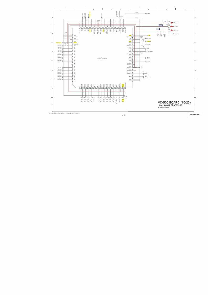
7/18/2019 SONY+HVR-HD1000 SERVICE MANUAL
http://slidepdf.com/reader/full/sonyhvr-hd1000-service-manual 55/425
4-7
HVR-HD1000J/HD1000U/HD1000N/HD1000E/HD1000P/HD1000C
A_
D_
(HN-047)
(Page 4-6)
CN6601Through the
Harness
CM-077(3/3)
XSYS_RST
CAM_VD_HS
CHCK
VST_C_RESET
XSYS_RST
AHS_TGVD
AHS_TGHD
3 6 9
B
7
C
8
D
G
E
H
1 4
A
2 5
F
C1205 0.1u B
C12240.1u
B
C12200.1u
B
C 1 2 1 7
0 . 1
u
B
C 1 2 1 1
X X
C1208 0.1u B
C 1 2 1 8
0 . 1
u
B
C1210 0.1u B
C1221 0.1u B
C 1 2 1 5
0 . 1
u
B
C 1 2 1 2
X X
C 1 2 1 9
0 . 1
u
B
C1207 0.1u B
C 1 2 1 6
0 . 1
u
B
C1209 0.1u B
C 1 2 1 3
0 . 1
u
B
C 1 2 1 4
0 . 1
u
B
C12220.1u
B
C12106.3
T
4M_DRVOUT3/6M_DRVOUT3
4M_DCOUT3/6M_DCOUT3
ADC_SO
ADC_SCK
XCS_ADC0
4M_DRVOUT4/6M_DRVOUT8
4M_DCOUT1/6M_DCOUT4
4M_DRVOUT1/6M_DRVOUT4
4M_DCOUT4/6M_DCOUT8
AD2_
AD2_
AD2_
AD2_
AD2_
AD2_
AD2_
AD2_
AD2_
AD2_
AD2_
AD2_
IC1201
VSP2436ZWDR
C 3 D
3
A 1
A 2
B 2
B 1
C 2
C 1
D 2
D 1
E 2
E 1
E 3
F 2
F 1
G 2 G 1 H 2 H 1
J 1
K 1
F 3
G 3
J 2
H 3
K2J3K3F4G4H4J4K4F5G5H5K5J5H6J6K6G6F6G7K7J7K8J8K9K10
J 9
J 1 0
H 9
H 1 0
H 8
H 7
G 8
G 9
G 1 0
F 8
F 1 0
F 9
E 8
E 9
E 1 0
D 8
D 1 0
D 9
C 7
C 1 0
C 9
C 8
B 1 0
B
9
A 1 0
A9 B8 A8 B7 A7 E7 D7 F7 E6 D6 A6 B6 C6 B5 A5 C5 D5 E5 A4 B4 C4 D4 E4 A3 B3R1208 XX
R1207 XX
R1210 XX
R1212 XX
R1201 XX
R1202 XX
R1203 XX
R1204 XX
R1211 XX
R 1 2 1 6
X X
4M_DCOUT6/6M_DCOUT7
R1205 XX
R1206 XX
4M_DRVOUT6/6M_DRVOUT7
AD2_
AD2_
4M_DRVOUT5/6M_CMGND
4M_DCOUT2/6M_CMGND
4M_DRVOUT2/6M_CMGND
4M_DCOUT5/6M_CMGND
C12106.3
T
REG_GND
REG_GND
4M_DCOUT4/6M_DCOUT8
4M_DRVOUT1/6M_DRVOUT4
4M_DCOUT1/6M_DCOUT4
4M_DRVOUT4/6M_DRVOUT8
4M_DRVOUT5/6M_CMGND
4M_DCOUT5/6M_CMGND
4M_DRVOUT2/6M_CMGND
4M_DCOUT2/6M_CMGND
4M_DRVOUT6/6M_DRVOUT7
4M_DCOUT6/6M_DCOUT7
4M_DRVOUT3/6M_DRVOUT3
4M_DCOUT3/6M_DCOUT3
4M_NC/6M_DRVOUT6
4M_NC/6M_DCOUT6
4M_NC/6M_DRVOUT2
4M_NC/6M_DCOUT2
4M_NC/6M_DRVOUT5
4M_NC/6M_DCOUT5
4M_NC/6M_DRVOUT1
4M_NC/6M_DCOUT1
REG_GND
REG_GND
REG_GND
REG_GND
D_1.5V
CAM_-1.0V
D_2.8V
CMOS_4.1V
A_2.8V
YAW_AD
PITCH_AD
AHS_SO
AHS_SCK
AHS_XCS0
R1231XX
R1232
22
R 1 2 1 4
1 k
CN1201 40P
1
2
3
4
5
6
7
8
9
10
11
12
13
14
15
16
17
18
19
20
21
22
23
24
25
26
27
28
29
30
31
32
33
34
35
36
37
38
39
40
C1206 0.1u B
R1209 XX
Input2
Input1
Input1
Input2
YAW_AD
A_4.1V
DCOUT6
D_1.5V
DRVOUT4
CHCK2/4M
DCOUT3
DRVOUT3
REG_GND
XSYS_RST
REG_GND
DRVOUT7
DCOUT7
DCOUT8
DRVOUT2
A_2.8V
XCS_AHS
REG_GND
REG_GND
A_-1.0V
D_2.8V
AHS_SO
DRVOUT8
TGVD
AHS_SCK
DRVOUT1
TGHD
PITCH_AD
DRVOUT5
DCOUT2
REG_GND
CHCK3/6M
DCOUT4
REG_GND
DCOUT5
REG_GND
REG_GND
VST_C_RESET
DRVOUT6
DCOUT1
(NC)D6_Y
S U B G
D V D D
D0_Z
(NC)D1_Y
D V S S
Z_
B_
P
DRVDD
Y_B_N(NC)
X_B_N
D V D D
D 1 3
_ X
Y_A_N(NC)
D 3
_ Z
D 1 1
_ X
AVSS(ID)
(NC)D11_Y
(NC)D3_Y
D8_Z
D0_X
R P
_ X
RP_Y(RN_X)
Z_A_N
Z_
B_
N
AVDD
S C L K
CM_Y(RN-Z)
D6_X
D 2
_ X
RN_Y(RP_X)
D4_Z
D 7
_ Z
AVSS(NC)
D 7
_ X
(NC)D7_Y
(NC)D12_Y
AVSS
Line_in
(ATPG)DRVSS
A V D D
R P
_ Z
D 1 2
_ X
S D L
V D
DRVSS
D 5
_ Z
D 4
_ X
AVDD
R N
_ X
D 1
_ X
S D A T A
D 1 3
_ Z
X_A_P
S E N
AVDD
H D
Z_A_P
D V S S
Y_B_P(NC)
(NC)D9_Y
D 1 2
_ Z
D 2
_ Z
Y_A_P(NC)
AVSS
X_B_P
(NC)D2_Y
AVDD
S U B G
AVSS
AVDD
D 1
_ Z
D 1 1
_ Z
L_
X D 5
_ X
L_
Z
(NC)D5_Y
D 1 0
_ Z
D 1 0
_ X
R S T
DRVDD
(NC)D10_Y
D 3
_ X
(NC)D13_Y
AVSS
(NC)D4_Y
L C K
(NC)D8_Y
D6_Z
C L P O B
X_
A_
N
C M
_ Z
C M
_ X
M C K
D 9
_ Z
DRVSS
R N
_ Z
L_Y(RP-Z)
D 8
_ X
(NC)D0_Y
D 9
_ X
Input2
CDS,A/D CONVERTER
05
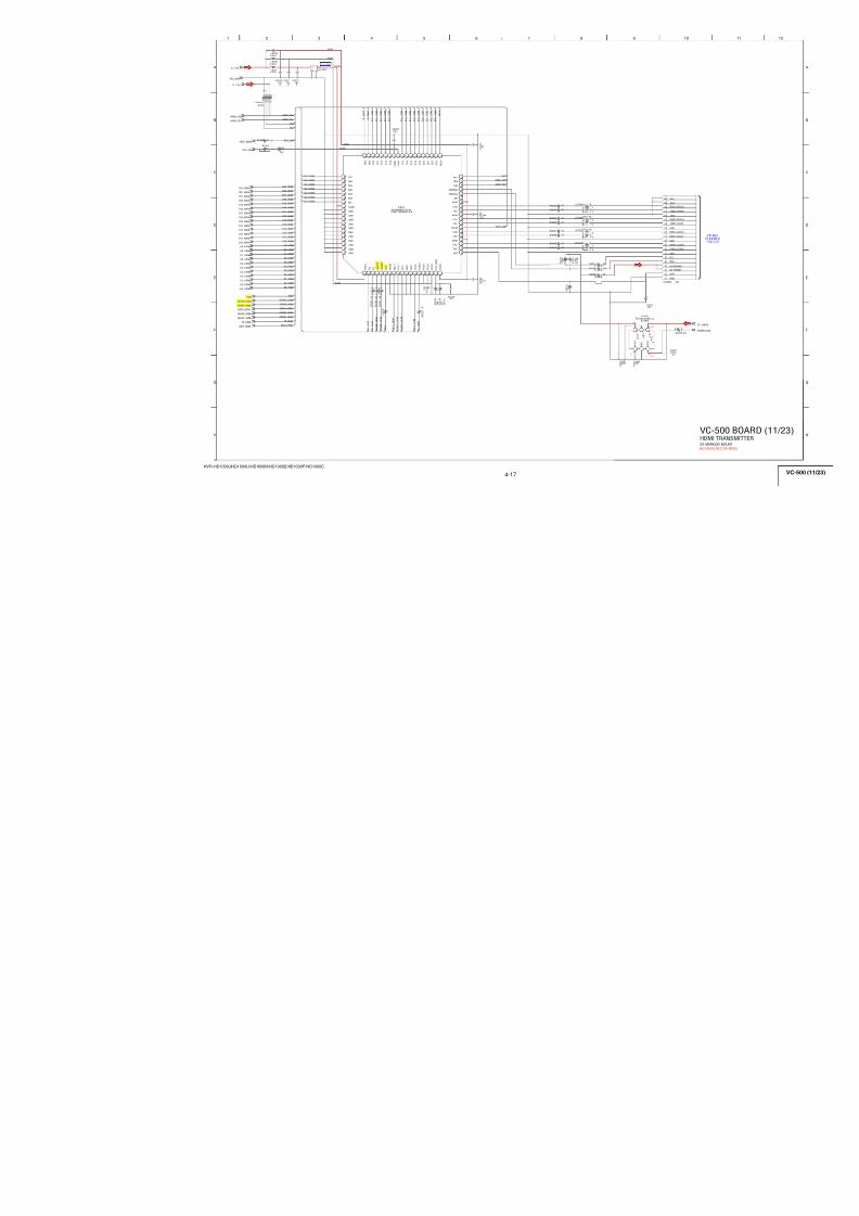
7/18/2019 SONY+HVR-HD1000 SERVICE MANUAL
http://slidepdf.com/reader/full/sonyhvr-hd1000-service-manual 56/425
4-8
HVR-HD1000J/HD1000U/HD1000N/HD1000E/HD1000P/HD1000C
D_2.8V
A_2.8V
CHCK
ADC_TGHD
ADC_TGVD
XSYS_RST
CAM_VD_HS
3 6 9
B
7
C
8
D
G
E
H
1 4
A
2 5
F
C 1 3 1 4
0 . 1
u
B
C13230.1u
B
C13200.1u
B
C 1 3 1 7
0 . 1
u
B
C 1 3 1 1
X X
C1306 0.1u B
C1308 0.1u B
C 1 3 1 8
0 . 1
u
B
C1310 0.1u B
C1321 0.1u B
C 1 3 1 5
0 . 1
u
B
C 1 3 1 2
X X
C 1 3 1 6
0 . 1
u
B
C1305 0.1u B
C1322
0.1uB
C 1 3 1 3
0 . 1
u
B
C1307 0.1u B
C 1 3 1 9
0 . 1
u
B
C1309 0.1u B
C132410u
6.3VTA
C132510u6.3V
TA
4M_NC/6M_DRVOUT1
CLPOB
4M_NC/6M_DCOUT1
4M_NC/6M_DRVOUT5
ADC_SCK
XCS_ADC0
4M_NC/6M_DCOUT5
ADC_SO
4M_NC/6M_DRVOUT6
4M_NC/6M_DCOUT2
4M_NC/6M_DRVOUT2
4M_NC/6M_DCOUT6
AD1_0
AD1_4
AD1_6
AD1_8
AD1_11
AD1_1
AD1_10
AD1_12
AD1_9
AD1_13
AD1_7
AD1_3
AD1_5
AD1_2
IC1301
VSP2436ZWDR
C 3
D 3
A 1
A 2
B 2
B 1
C 2
C 1
D 2 D 1 E 2
E 1
E 3
F 2
F 1
G 2
G 1
H 2
H 1
J 1
K 1
F 3
G 3
J 2
H 3
K2J3K3F4G4H4J4K4F5G5H5K5J5H6J6K6G6F6G7K7J7K8J8K9K10
J 9
J 1 0
H 9
H 1 0
H 8
H 7
G 8
G 9
G 1 0
F 8
F 1 0
F 9
E 8
E 9
E 1 0
D 8
D 1 0
D 9
C 7
C 1 0
C 9
C 8
B 1 0
B 9
A 1 0
A9 B8 A8 B7 A7 E7 D7 F7 E6 D6 A6 B6 C6 B5 A5 C5 D5 E5 A4 B4 C4 D4 E4 A3 B3
L130110uH
L130210uH
R1308 XX
R1307 XX
R1306 XX
R1305 XX
R1301 XX
R1302 XX
R1303 XX
R1304 XX
R13141k
R 1 3 1 6
X X
AD3_2
AD3_13
AD3_3
AD3_6
AD3_4
AD3_0
AD3_7
AD3_1
AD3_11
AD3_10
AD3_9
AD3_12
AD3_8
AD3_5
CL1301
CL1302
R1346
XX
R1347
0
X_A_P
(NC)D13_Y
(NC)D4_Y
(NC)D8_Y
D6_Z
X_
A_
N
C M
_ X
D 9
_ Z
R N
_ Z
D 8
_ X
D 9
_ X
(NC)D6_Y
Input1
S U B G
D V D D
D0_Z
(NC)D1_Y
D V S S
Z_
B_
P
DRVDD
Y_B_N(NC)
X_B_N
D V D D
D 1 3
_ X
Y_A_N(NC)
D 3
_ Z
D 1 1
_ X
AVSS(ID)
(NC)D11_Y
(NC)D3_Y
D8_Z
D0_X
R P
_ X
RP_Y(RN_X)
Z_A_N
Z_
B_
N
AVDD
S C L K
CM_Y(RN-Z)
D6_X
D 2
_ X
RN_Y(RP_X)
D4_Z
D 7
_ Z
AVSS(NC)
D 7
_ X
(NC)D7_Y
(NC)D12_Y
AVSS
Line_in
(ATPG)DRVSS
A V D D
R P
_ Z
D 1 2
_ X
S D L
V D
DRVSS
D 5
_ Z
D 4
_ X
AVDD
R N
_ X
D 1
_ X
S D A T A
D 1 3
_ Z
S E N
AVDD
H D
Z_A_P
D V S S
Y_B_P(NC)
(NC)D9_Y
D 1 2
_ Z
D 2
_ Z
Y_A_P(NC)
AVSS
X_B_P
(NC)D2_Y
AVDD
Input2
S U B G
Input2
AVSS
AVDD
D 1
_ Z
D 1 1
_ Z
L_
X D 5
_ X
L_
Z
(NC)D5_Y
Input1
D 1 0
_ Z
D 1 0
_ X
R S T
DRVDD
(NC)D10_Y
D 3
_ X
AVSS
L C K
C L P O B
C M
_ Z
M C K
DRVSS
L_Y(RP-Z)
(NC)D0_Y
CDS,A/D CONVERTER
05
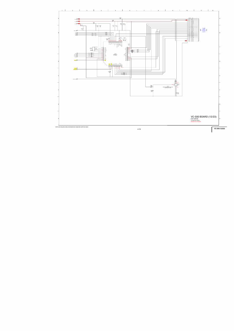
7/18/2019 SONY+HVR-HD1000 SERVICE MANUAL
http://slidepdf.com/reader/full/sonyhvr-hd1000-service-manual 57/425
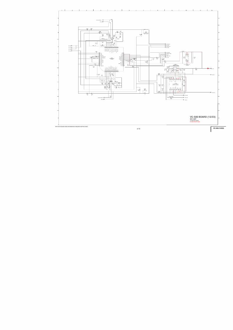
7/18/2019 SONY+HVR-HD1000 SERVICE MANUAL
http://slidepdf.com/reader/full/sonyhvr-hd1000-service-manual 58/425
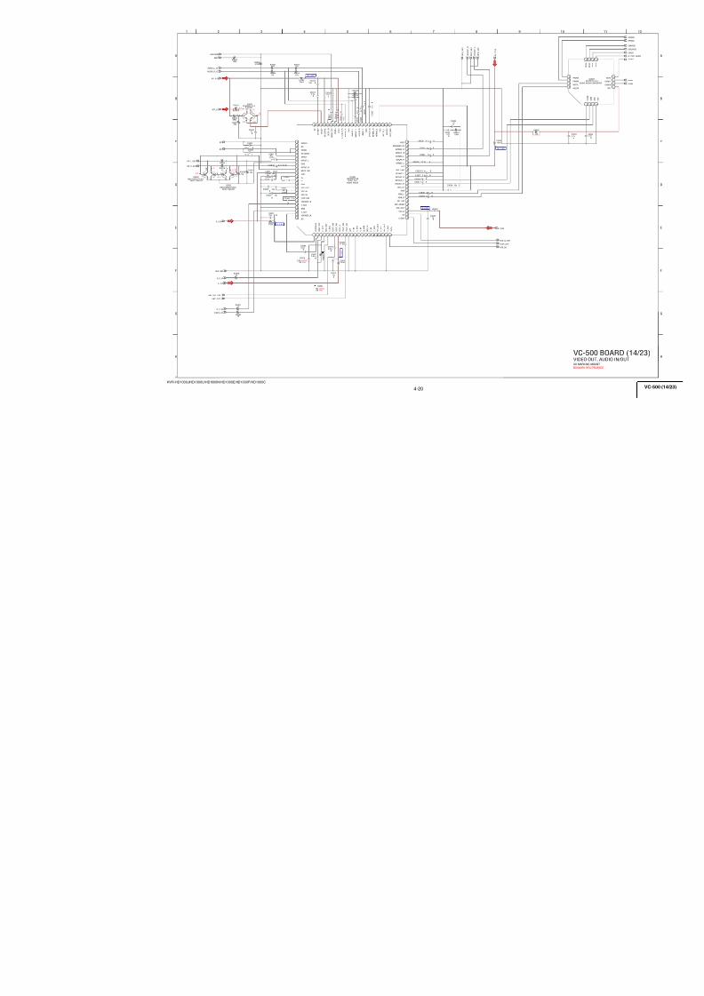
7/18/2019 SONY+HVR-HD1000 SERVICE MANUAL
http://slidepdf.com/reader/full/sonyhvr-hd1000-service-manual 59/425
4-11
HVR-HD1000J/HD1000U/HD1000N/HD1000E/HD1000P/HD1000C
D_2.5V
2 . 7
0
2.8
4.6
2 . 8
2 . 8
2
2
0 0 0 2 . 7
2 . 8
2 . 8
0
2 . 8
4.6
2
0
3 6 9
B
7
C
8
D
G
E
H
1 4
A
2 5
F
SD_A2
SD_XWE
SD_BA0
SD_XRAS
SD_DQ4
SD_DQM
SD_DQ2
SD_DQ8
SD_XCS
SD_A5
SD_CK
SD_DQ13
SD_DQ14
SD_XCAS
SD_BA0
SD_DQ6
SD_DQ6
SD_DQ4SD_DQ15
SD_A0
SD_XCAS
SD_A8
SD_BA1
SD_A7
SD_CKE
SD_DQ2
SD_XRAS
SD_A1
SD_DQ0
SD_A11
SD_DQ9
SD_XWE
SD_DQ7
SD_DQ5
SD_A9
SD_DQ12
SD_DQ1
SD_DQ11
SD_DQ3
SD_DQ8
SD_BA1
SD_XCS
SD_A6
SD_A10
SD_A4
SD_A3
SD_DQM
SD_DQ3
SD_DQ5
SD_DQ7
SD_DQ9
SD_DQ11
SD_DQ12
SD_DQ13
SD_DQ14
SD_DQ15
SD_A0
SD_A1
SD_A2
SD_A3
SD_A4
SD_A5
SD_A6
SD_A7
SD_A8
SD_A9
SD_A10
SD_A11
SD_DQ0
SD_DQ1
SD_DQ10
SD_DQ10
SD_CKE
SD_CK
S D
_ A 5
SD_DQ7
SD_DQ19
S D
_ A 2
SD_DQ28
S D
_ A 7
SD_DQ10
SD_DQ29
SD_DQ11
SD_DQ24
S D
_ A 1
SD_DQ18
SD_DQ15
S D
_ A 6
SD_DQ13
S D
_ A 1 0
SD_DQ14
S D
_ A 3
S D
_ X W E
SD_DQ26
SD_DQ17
SD_DQ9
SD_DQ30
S D
_ A 9
SD_DQ25
S D
_ X C S
S D
_ D Q 5
SD_DQ12
SD_DQ8
SD_DQ23
SD_DQ20
S D
_ D Q 2
S D
_ X C A S
SD_DQ31
SD_DQ21
S D
_ A 8
S D
_ D Q 3
S D
_ A 1 1
S D
_ D Q M
S D
_ C K
S D
_ D Q 0
S D
_ X R A S
S D
_ A 4
SD_DQ22
S D
_ D Q 6
S D
_ D Q 1
SD_DQ16
S D
_ D Q 4
SD_DQ27
S D
_ A 0
REG_GND
D_2.5V
FB1901
C1901XX
C19030.1u
B
C19020.1u
B
S D
_ B A 0
S D
_ B A 1
IC1901
EDS2532JEBH-75TT-E
G8
A 0
G9
A 1
F7
A 2
F3
A 3
G1
A 4
G2
A 5
G3
A 6
H1
A 7
H2
A 8
J3
A 9
G7
A 1 0
H9
A 1 1
H3
N C
J7
B A 0
H8
B A 1
R8
D Q 0
N7
D Q 1
R9
D Q 2
N8
D Q 3
P9
D Q 4
M8
D Q 5
M7
D Q 6
L 8
DQ7
L 2DQ8
M 3
DQ9
M 2
DQ10
P 1DQ11
N 2
DQ12
R 1
DQ13
N 3
DQ14
R 2
DQ15
E 8DQ16
D 7
DQ17
D 8
DQ18
B 9
DQ19
C 8DQ20
A 9
DQ21
C 7
DQ22
A 8DQ23
A 2DQ24
C 3DQ25
A 1DQ26
C 2
DQ27
B 1
DQ28
D 2
DQ29
D3
D Q 3 0
E2
D Q 3 1
K9
D Q M 0
K1
D Q M 1
F8
D Q M 2
F2
D Q M 3
J8
X C S
K8
X W E
J9
X R A S
K7
X C A S
J2
C K E
J1
C L K
E3
N C
K2
N C
K3
N C
H7
N C
E7
N C
R7
V D D
L7
V D D
F9
V D D
A7
V D D
B2
V D D Q
E 1 VDDQ
L 1 VDDQ
P 2
VDDQ
P 7
VDDQ
N 9
VDDQ
M 9
VDDQ
D 9 VDDQ
C 9
VDDQ
B 7
VDDQ
A 3 VSS
F 1 VSS
L 3
VSS
R 3
VSS
B 3
VSSQ
C 1
VSSQ
D 1
VSSQ
M 1
VSSQ
N 1
VSSQ
P 3
VSSQ
P 8 VSSQ
L 9 VSSQ
E 9 VSSQ
B 8 VSSQ
R 1 9 0 5
X X
SD_A5
SD_DQ6
SD_A7
SD_DQ4
SD_BA1
SD_A11
SD_DQ12
SD_A4
SD_A3
C19050.1u B
SD_DQ10
SD_XCS
SD_A9
SD_DQ5
SD_DQM
SD_DQ15
SD_DQ1
SD_DQ8
SD_DQ0
SD_A2
R 1 9 0 6
1 0 0 k
SD_CK
SD_A8
SD_DQ3
SD_CKE
SD_DQ14
SD_DQ13
SD_A0
SD_A10
SD_XCAS
C19040.1u
B
SD_DQ2
SD_A1
SD_DQ9
SD_DQ11
SD_DQ7
REG_GND
IC1902XX
A 1
A 2
A 3
A 7
A 8
A 9
B 1
B 2
B 3
B 7
B 8
B 9
C 1
C 2
C 3
C 7
C 8
C 9
D 1
D 2
D 3
D 7
D 8
D 9
E 1
E 2
E 3
E 7
E 8
E 9
F 1
F 2
F 3
F 7
F 8
F 9
G 1
G 2
G 3
G 7
G 8 G 9
H 1 H 2 H 3 H 7 H 8 H 9
J 1
J 2
J 3
J 7
J 8
J 9
SD_XWE
SD_A6
R1907100k
SD_XRAS
SD_BA0
S D
_ C K E
C190610uB
C1907XX
FL1901
R1939 XX
REG_GND
C20052.2u
B
C20121uB
L I N E
_ C N T 2
L I N E
_ C N T 3
L I N E
_ C N T 1
X D 4 C N
IC2001
TLS26A100PFBR
1Cont_in1A
2Vin1
3VCC46_1
4Vin2
5GND_1
6Vin3
7VCC46_2
8Vin4
9GND_2
1 0
Vin5
1 1
LPF1_OFF
1 2
Vin6
13
V o l_ Y 1
14
V o l_ Y 2
15
V i n 7
16
V o l_ P 1
17
V o l_ P 2
18
P S 1
19
S / X P
20
X C S
21
V C C
_ D 2
. 8 V
22
C K
23
S I
24
D_
G N D
MON
TR
TES
V
V
37
S E L 3
38
S E L 2
39
S E L 1
40
D E T
_ I N
41
C o n t_ o u t 3
42
C o n t_ o u t 2
43
C o n t_ o u t 1
44
D E T
_ O U T
45
C o n t_ i n 3 B
46
C o n t_ i n 3 A
47
C o n t_ i n 2
48
C o n t_ i n 1 B
C201010uB
X L I N E
_ C N T 1 B
LINE_OUT_C/PB
LINE_OUT_Y
LINE_OUT_PR
L 2 0
0 1
1 0 u H
C20042.2u
B
X L I N E
_ C N T 2
XLINE_CNT1A
X P S V
_ D 4
X L I N E
_ C N T 3 A
A_4.6V
X L I N E
_ C N T 3 B
D 3 C N
C201710uB
C20032.2u
B
C20111uB
DQ5
Vdd
VddQ
A8
Vss
BA1
VssQ
DQ14
DQ8
DQ12
CSP
NC
VddQ
CLK
DQ13
RAS
DQ10
DQ9
DQ4
Vdd
A6
BA0
A0
A5
Vddq
A7
DQ6
DQ2
NC(A12)
Vdd
CKE
CAS
A1
A10
A11
DQ11
WE
UDQM
VssQ
Vssq
A3
CS
DQ1
DQ7
Vssq
A4
Vss
LDQM
DQ15 A2
A9
Vss
DQ3
Vddq
DQ0
256M SDRAM
COMPONENT OUT AMP
05
1
3
2
4
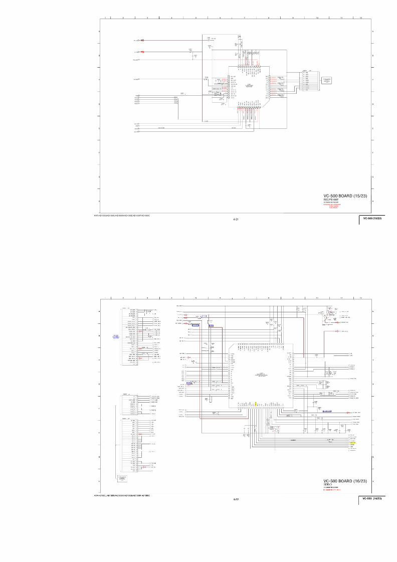
7/18/2019 SONY+HVR-HD1000 SERVICE MANUAL
http://slidepdf.com/reader/full/sonyhvr-hd1000-service-manual 60/425
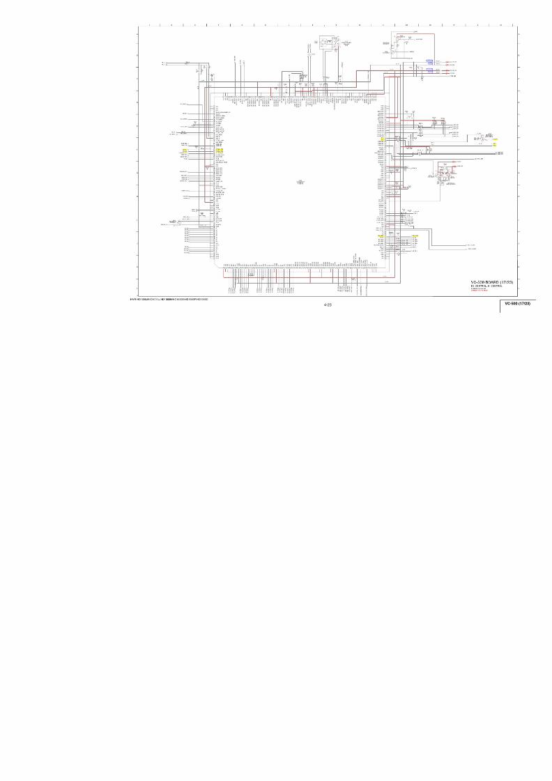
7/18/2019 SONY+HVR-HD1000 SERVICE MANUAL
http://slidepdf.com/reader/full/sonyhvr-hd1000-service-manual 61/425
4-13
HVR-HD1000J/HD1000U/HD1000N/HD1000E/HD1000P/HD1000C
D_1.8V
X R S T
_ V T R
3 6 9
B
7
C
8
D
G
E
H
1 4
A
2 5
F
C24030.1u
C
C24020.1u
C
C240122u4V
D_1.8V
BMDT43
BMDT47
B M D T 4 0
BMDT31
O M D Q 4
O M C K E
B M D T 2 1
O M C L K
BMDT36
BMDT35
B M D T 2 3
O M C L K X
B M D T 2 2
BMDT38
O M A D 0 1
O M D Q 3
BMDT30
O M W E X
BMDT17
BMDT24
BMDT28
O M A D 0 8
BMDT41
BMDQS3
BMDT34
BMDT42
BMDT37
O M C E X
B M D Q S 0
O M A D 0 7
O M A D 1 0
BMDT18
O M A D 0 9
BMDT33
REG_GND
O M A D 0 0
B M D T 1 6
O M A D 0 6
B M D T 1 9
O M A D 0 2
O M C S X
O M A D B 0
O M D Q 2
O M A D 1 2
BMDT46
O M A D 0 5
B M D T 4 5
BMDQS2
O M D Q 5
O M A D 0 3
B M D T 2 0
B M D T 3 9
B M D Q S 1
O M A D B 1
BMDT32
BMDT27
BMDT25
O M R S X
O M A D 0 4
BMDT44
BMDT29
BMDT26
O M A D 1 1
R24010
D X X A 0 2
_ S I M
D X X A 0 3
_ S I M
D 2 6 A 0 2
_ S I M
D X X A 1 2
_ S I M
D X X A 0 1
_ S I M
D 2 5 A 0 1
_ S I M
D X X A 0 5
_ S I M
R D X
_ S I M
D X X A 0 6
_ S I M
D 2 7 A 0 3
_ S I M
D X X A 0 7
_ S I M
D 2 4 A 0 0
_ S I M
D X X A 0 8
_ S I M
D31A07_SIM
DXXA00_SIM
D30A06_SIM
D29A05_SIM
D 2 8 A 0 4
_ S I M
X C S
_ F L A S H
W R 0 1
_ S I M
IC2402S29AL016D70BFI013
E1
A 0
D1
A 1
C1
A 2
A1
A 3
B1
A 4
D2
A 5
C2
A 6
A2
A 7
B5
A 8
A5
A 9
C5
A 1 0
D5
A 1 1
A4
W E #
B4
R E S E T #
A3
R Y / B Y #
F6
B Y T E #
F1
C E #
G1
O E #
C4
N C
E2
D Q 0
H2
D Q 1
E3
D Q 2
H3
D Q 3
H4
D Q 4
E 4
DQ5
H 5
DQ6
E 5
DQ7
F 2
DQ8
G 2
DQ9
F
3DQ10
G 3
DQ11
F 4
DQ12
G 5
DQ13
F 5
DQ14
G 6
DQ15/A-1
H 1
VSS
D X X A 0 9
_ S I M
D X X A 1 0
_ S I M
D X X A 0 4
_ S I M
D X X A 1 1
_ S I M
R 2 4 0 2
0
IC2401
HYE18M256320CFX-7.5
G8
/ C A S
G9
R A S
F7
N C
F3
N C
G1
C K E
G2
C K
G3
C K
H1
A 9
H2
A 1 1
J3
A 8
G7
/ W E
J7
A 1 0
H8
B A 0
R8
D Q 0
N7
D Q 3
R9
V D D
N8
D Q 4
P9
V S S Q
M8
D Q 6
M7
D Q 5
L8
D Q S O
L2
D Q S 1
M 3
DQ10
M 2
DQ9
P 1
VDDQ
N 2
DQ11
R 1
VSS
N 3
DQ12
R 2DQ15
E 8
DQ52
D 7
DQ21
D 8
DQ22
B 9
VSSQ
C 8
DQ20
A 9
VDD
C 7
DQ19
A 8
DQ16
A 2
DQ31
C 3
DQ28
A 1
VSS
C 2
DQ27
B 1
VDDQ
D 2
DQ25
D 3
DQ26
E 2
DQS3
K9
A 3
K1
A 4
F8
D M 2
F2
D M 3
J8
A 0
K8
D M O
J9
A 1
K7
A 2
J2
A 7
J1
A 6
E3
D Q 2 4
E7
D Q 2 3
H3
A 1 2
H7
I C S
H9
B A 1
K2
D M 1
K3
A 5
A7
V D D Q
F9
V S S
L7
D Q 7
R7
V D D Q
B2
D Q 2 9
B 7
DQ17
C 9
VDDQ
D 9
VSSQ
E 1
VSSQ
L 1
VSSQ
M 9
VSSQ
N 9
VDDQ
P 2
DQ13
P 7
DQ1
A 3
VSSQ
F 1
VDD
L 3
DQ8
R 3
VSSQ
B 3
DQ30
B 8
DQ18
C 1
VSSQ
D 1VDDQ
E 9
VDDQ
L 9
VDDQ
M 1
VDDQ
N 1
VSSQ
P 3
DQ14
P 8
DQ2
/ A P
256M DDR-SDRAM
16M FLASH
05
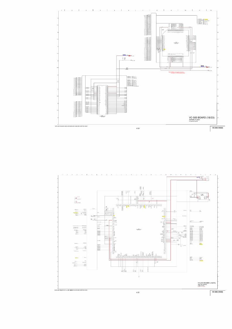
7/18/2019 SONY+HVR-HD1000 SERVICE MANUAL
http://slidepdf.com/reader/full/sonyhvr-hd1000-service-manual 62/425
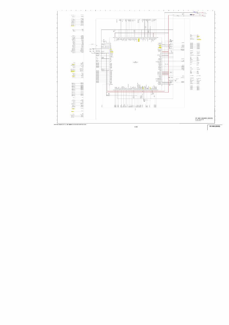
7/18/2019 SONY+HVR-HD1000 SERVICE MANUAL
http://slidepdf.com/reader/full/sonyhvr-hd1000-service-manual 63/425
4-15
HVR-HD1000J/HD1000U/HD1000N/HD1000E/HD1000P/HD1000C
A_2.8V
D_2.8V
C
9
A
I
H
5
F
3 13762
E
124
L
D
1
G
11
K
B
108
J
PD05
IDIR0
XIACC0
XPEN0
PD03
PD07
PD02
PD01
FR1
PD04
PD06
PD00
PWD
LPS
IC_3401_PLL_ON
P D 0 1
P D 0 2
P D 0 3
P D 0 4
P D 0 5
P D 0 6
P D 0 7
O F R 2
P D 0 0
DXXA00_SIM
DXXA01_SIM
DXXA02_SIM
DXXA03_SIM
DXXA04_SIM
DXXA05_SIM
DXXA06_SIM
XPEN0
XIACC0
IDIR0
DXXA07_SIM
R D X
_ S I M
W R 0 1
_ S I M
X C S
_ I C
_ 3 4 0 1
D 2 4 A 0 0
_ S I M
D 2 5 A 0 1
_ S I M
D 2 6 A 0 2
_ S I M
D 2 7 A 0 3
_ S I M
D 2 8 A 0 4
_ S I M
D 2 9 A 0 5
_ S I M
D 3 0 A 0 6
_ S I M
D 3 1 A 0 7
_ S I M
XRST_PHY
XRST_LINK
PCLK0
FCLR0
FCLR0
CNA
P C L K 0
PCLK0
T R R T
FR1
XPEN0
PD06
C34160.1u
B
R340210k
REG_GND
R340451
±0.5%
A_2.8V
PCLK0
C34090.1u
C340110u
C34071u
B
C 3 4 1 4 1 u B
IDIR0
R340351
±0.5%
PD05
PD00
PD01
R340651
±0.5%
PD02
R340110k
L3401 10uH
PD03
C34150.1u
B
R3408 1k
FB3401
FR1
C 3 4 1 2
1 2 p
C H
D_2.8V
PD04
C34044.7u
B
R340551
±0.5%
XIACC0
C34050.1u
C34201u
B
TPB+
TPB-
C34031uB
TPA-
R34096200±0.5%
R3412 1k
X340124.576MHz
C3402270p
TPA+
PD07
C 3 4 1 1
1 2 p
C H
C 3 4 1 8
0 . 1
u B
C3410XX
R34070
C3408XX
C3417XX
R34130
R 3 4 1 4
X X
FCLR0
LF3403
R 3 4 1 5
X X
R3416 XX
B1 C3 D4 C1 C2 D2 D1 E5 E4 E1 E2 F5 F1 F2 G5 G1 F4 G2 H1 G4 H2 J1 H4 J2 K1 H5 L1 K2
L 2
M 1 M 2 L 3
M 3 L 4
M 4 J 4
J 5
M 5 L 5
H 6 M 6 L 6
J 6
M 7 J 7
L 7
M 8 L 8
H 7 M 9 L 9
J 8 M 1 0 L 1 0 J 9 M 1 1
L11M12L12K11K12J11J12H8H9H12H11G8G12G11G9F12F9F11E12F8E11D12E9D11C12E8C11B12
D 9
B 1 1
A 1 2
E 7
A 1 1
E 6
B 1 0
A 1 0
D 8
B 9
A 9
D 7
B 8
A 8
D 6
B 7
A 7
A 6
B 6
D 5
A 5
A 4
B 5
B 4
A 3
B 3
B 2
A 2
A 1
X I N T
T E S T 0
H D 7
V S S
X O
X C S
H D 5
H D 0
X R W
H D 1
R 1
T M O D E 0
V S S
V D D
H D 3
H D 2
H D 4
V D D
V S S
HDA0
R 0
P M L T
T M O D E 1
H D 6
A L E
X R D
H M L T
X I
V S S
HDA2
REGOUT1
TEST1
HDA4
HDA1
HDA5
VDD
VSS
P D 0 0
PMODE0
TEST3
XIACC0
XPEN0
VDD
FR0
TEST2
FCLR0
HDA6
HDA3
VDD
HDA7
VSS
PCLK0
REGENZ
XRESTL
VSS
VSS
IDIR0
V D D
X P E N 1
P D 0 6
T E S T 4
V S S
P D 0 5
FCLR1
P D 0 3
P C L K 1
P D 0 7
V D D
P D 1 1
PD13
X I A C C 1
V D D
V S S
V S S
P D 0 1
P D 0 2
VSS
V S S
P D 1 2
I D I R 1
T E S T 6
F R 1
O F R
T E S T 5
P D 1 0
P D 0 4
R E G O U T 2
LPS
TEST7
VDD
VSS
XRESETP
VDDA
VDD
VSSA
VDDA
TPAP
VSSA
TPBIAS
TPBP
VSSA
TPAN
VDDA
PWD
VSS
PLLON
VSS
MSP100
TPBN
REGOUTPLL
VSSPLL
VDDPLL
CNA
D_2.8V D_2.8V
D_2.8V
IC3401
SN200507002ZZCRHDV/DV i.LINK INTERFACE
05
4
3
2
1
8
7
6
5
3 4
1 2
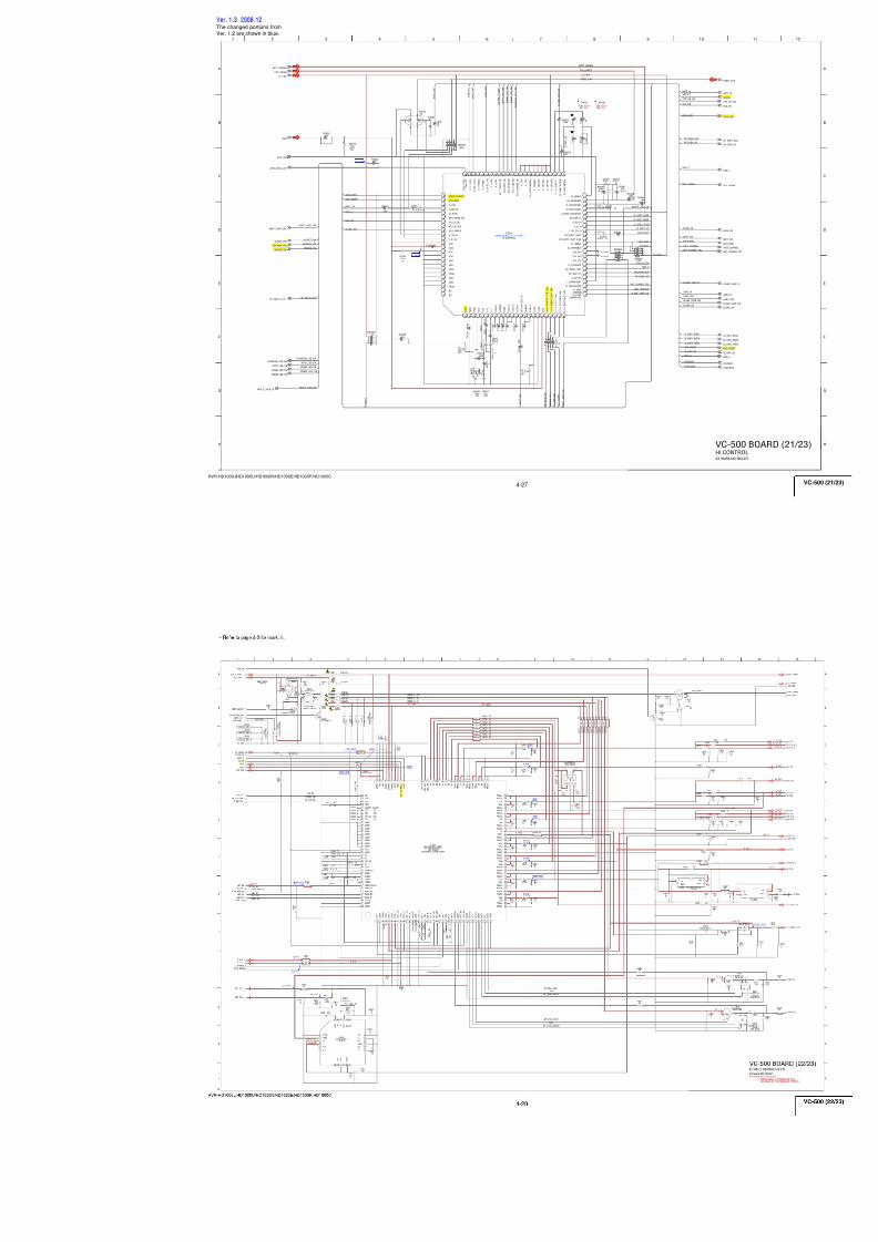
7/18/2019 SONY+HVR-HD1000 SERVICE MANUAL
http://slidepdf.com/reader/full/sonyhvr-hd1000-service-manual 64/425
4-16
HVR-HD1000J/HD1000U/HD1000N/HD1000E/HD1000P/HD1000C
D_2.8V
D_1.5V
XRST_HDMI
IDCK
H M
_ V D
H M
_ H D
H S Y N C
_ H D M I
VSYNC_HDMI
D
C
6
B
A
53 4
F
2
E
1
C31120.1u
B
C31110.1u
B
C3116XX
C31000.1u
BC3114
10uB
C311310u
BC3110
0.1u B
C31050.1u
B
C31090.1u
B
C3107
0.1u B
CK_HM
CK74MFO
H M
_ Y 7
H M
_ Y 2
H M
_ B 2
H M
_ B 6
H M
_ R 0
CK256FSO
CK64FSO
CKFSO
H M
_ B 4
VSP_SO
H M
_ Y 4
HM_R6
IC_2101_ADAO2
HM_Y1
X C S
_ I C
_ 3 1 0 1
IC_2101_ADAO1
H M
_ B 3
H M
_ Y 3
H M
_ Y 5
HM_Y0
H M
_ Y 6
H M
_ R 4
H M
_ R 5
H M
_ R 3
H M
_ R 1
H M
_ B 7
H M
_ B 5
H M
_ B 1
H M
_ R 2
H M
_ R 7
H M
_ B 0
H M
_ F L D
XVSP_SCK
D13_HDMI
D18_HDMI
D16_HDMI
D22_HDMI
D10_HDMI
D3_HDMI
D12_HDMI
D20_HDMI
D 2
_ H D M I
D 1
_ H D M I
F S
_ H D M I
D 0
_ H D M I
A D A O 2
_ H D M I
A D A O 1
_ H D M I
D14_HDMI
D8_HDMI
D17_HDMI
D6_HDMI
D15_HDMI
D19_HDMI
D21_HDMI
D9_HDMI
D E
_ H D M I
2 5 6 F S
_ H D M I
64FS_HDMI
D7_HDMI
D11_HDMI
D4_HDMI
D5_HDMI
D23_HDMI
VSP_SI
IC3101T6UL2XBG-0002(EO2)
A1
N C
A2
H M
_ R 5
A3
H M
_ R 3
A4
H M
_ R 1
A5
H M
_ B 7
A6
H M
_ B 5
A7
H M
_ B 3
A8
H M
_ B 1
A9
H M
_ Y 7
A10
H M
_ Y 5
A11
N C
A12
N C
B1
N C
B2
H M
_ R 4
B3
H M
_ R 2
B4
H M
_ R 0
B5
H M
_ B 6
B6
H M
_ B 4
B7
H M
_ B 2
B8
H M
_ B 0
B9
H M
_ Y 6
B10
H M
_ Y 4
B11
H M
_ Y 3
B12
H M
_ Y 2
C1
H M
_ R 7
C2
X C S
C3
V S S
C4
H M
_ F L D
C5
V D D S ( 3
. 0 V )
C6
H M
_ V D
C7
H M
_ H D
C8
V D D S ( 3
. 0 V )
C 9VSS2
C 1 0
VSS2
C 1 1
ADAO1
C 1 2
HM_Y1
D 1HM_R6
D 2IC_3101_SI
D 3IC_3101_SO
D 4VDDS(3.0V)
D 5VSS2
D 6VDDC(1.5V)
D 7VSS2
D 8VDDC(1.5V)
D 9VDDS(3.0V)
D 1 0
FCK
D 1 1
VSS2
D 1 2
HM_Y0
E 1HMCK
E 2VSS2
E 3VSS2
E 4VDDC(1.5V)
E 9ADAO2
E 1 0
BCK
E 1 1
LRCK
E 1 2
VDDC(1.5V)
F 1VDDC(1.5V)
F 2XSCLK
F 3TBIST
F 4XRST
F 9VSS2
F 1 0
SCK
F 1 1
VDDC(1.5V)
F 1 2
IDCK
G1
H M 7 4 C K
G2
V S S 2
G3
T S C A N
G4
V D D S ( 3
. 0 V )
G9
S D 0
G10
S D 1
G11
M C L K
G12
V S S
T E S T 0
H1
T E S T 1
H2
V S S 2
H3
T E S T 2
H4
V D D C ( 1
. 5 V )
H9
V D D S ( 3
. 3 V )
H10
V S S 2
H11
S E L C K
H12
D 0
J1
V D D C ( 1
. 5 V )
J2
V D D S ( 3
. 3 V )
J3
V D D S ( 3
. 3 V )
J4
V S S 2
J5
V D D C ( 1
. 5 V )
J6
V D D S ( 3
. 3 V )
J7
V S S 2
J8
H S Y N C
J9
W S
J10
V S S
J11
D E
J12
D 1
K1
D 2
K2
V S S
K3
V D D S ( 3
. 3 V )
K4
VSS K 5
VDDS(3.3V) K 6
VSS K 7
VDDC(1.5V) K 8
VSS K 9
VSYNC K 1 0
VDDS(3.3V) K 1 1
D23 K 1 2
D3 L 1
D4 L 2
D5 L 3
D7 L 4
L 5
D9
L 6
D11
L 7
D13
L 8
D15
L 9 D17
L 1 0
D19
L 1 1
D21
L 1 2
NC
M 1
NC
M 2
NC
M 3
D6
M 4
D8
M 5
D10
M 6
D12
M 7
D14
M 8
D16
M 9
D18
M 1 0
D20
M 1 1
D22
M 1 2
NC
R3103XX
C3102
0.1u B
74.25MHz
74.25MHz
HDMI SIGNAL PROCESSOR
XX MARK
HDMI
VC-
05
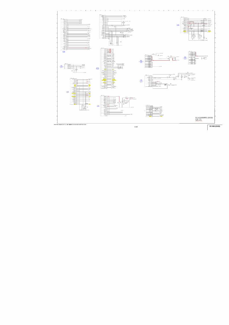
7/18/2019 SONY+HVR-HD1000 SERVICE MANUAL
http://slidepdf.com/reader/full/sonyhvr-hd1000-service-manual 65/425
4-17
HVR-HD1000J/HD1000U/HD1000N/HD1000E/HD1000P/HD1000C
D_1.8V
HSYNC_HDMI
IDCK
VSYNC_HDMI
TMD
TMD
8.3
5
1.32.8
3 6 9
B
7
C
8
D
G
E
H
1 4
A
2 5
F
IDCK
DE_HDMI
64FS_HDMI
FS_HDMI
256FS_HDMI
VSYNC_HDMI
HSYNC_HDMI
REG_GND
D
1 5
_ H D M I
D
1 6
_ H D M I
D
1 7
_ H D M I
D
1 8
_ H D M I
D
1 9
_ H D M I
D
2 0
_ H D M I
D
2 1
_ H D M I
D
2 2
_ H D M I
D
2 3
_ H D M I
D 0
_ H D M I
A D A O 1
_ H D M I
A D A O 2
_ H D M I
D 8
_ H D M I
D 9
_ H D M I
D
1 0
_ H D M I
D
1 1
_ H D M I
D
1 2
_ H D M I
D
1 3
_ H D M I
D
1 4
_ H D M I
D7_HDMI
D6_HDMI
D5_HDMI
D4_HDMI
D3_HDMI
D2_HDMI
D1_HDMI
M D A
MCL
HDMI_SDA
HDMI_SCL
HDMI_SDA
HDMI_SCL
MCL
MDA
REG_GND
I D C K
F S
_ H D M I
D23_HDMI
D22_HDMI
D21_HDMI
D20_HDMI
D19_HDMI
D18_HDMI
D17_HDMI
D16_HDMI
D15_HDMI
D14_HDMI
D13_HDMI
D12_HDMI
D11_HDMI
D10_HDMI
D9_HDMI
D8_HDMI
D7_HDMI
D6_HDMI
D5_HDMI
D4_HDMI
D3_HDMI
D2_HDMI
D1_HDMI
D0_HDMI
ADAO2_HDMI
ADAO1_HDMI
2 5 6 F S
_ H D M I
6 4 F S
_ H D M I
D E
_ H D M I
H S Y N C
_ H D M I
V S Y N C
_ H D M I
C32030.1u
B
C 3 2 0 4
0 . 1
u B
C 3 2 0 5
0 . 1
u B
C32020.1u
B
D19_HDMI
D12_HDMI
D11_HDMI
D14_HDMI
D18_HDMI
D10_HDMI
D1_HDMI
D13_HDMI
D16_HDMI
256FS_HDMI
D8_HDMI
D5_HDMI
D2_HDMI
D0_HDMI
D7_HDMI
D22_HDMI
D21_HDMI
D20_HDMI
D23_HDMI
D15_HDMI
XRST_HDMI
HDMI_SDA
HDMI_SCL
ADAO2_HDMI
ADAO1_HDMI
FS_HDMI
64FS_HDMI
D4_HDMI
D3_HDMI
DE_HDMI
D6_HDMI
D17_HDMI
D9_HDMI
R3 212 XX
R3211 XX
R3210 47
R3206 47
R3209 47
R3208 47
R3207 47
R3205 47
R3204 47
R3203 47
IC3202TK11250CMCL-G
1
C O N T
2
G N D
3
N O I S E
4
V O U T
G N D
5
V I N
6
C32060.01uB
C320.2
B
C32090.22uB
R 3 2 1 8
0
R 3 2 1 9
4 7 k
R 3 2 2 0
1 8 0 0
1 / 1 6 W
R 3 2 2 1
1 8 0 0
1 / 1 6 W
R3222 XX
R3223
XXREG_GND
R3224XX
REG_GND
FL3201D_1.8V
D_2.8V
R3226 XX
R 3 2 2 9
9 1 0
± 0
. 5 %
R 3 2 3 3
0D3202XX
R 3 2 3 4
3 6 k
CN3202
1
2
3
4
5
6
7
8
910
11
12
13
14
15
16
17
18
19
20
RB4701
4700
C321010u
B
C321110u
B
C321210u
B
LF3201
LF3202
LF3203
LF3204
L32014.7uH
L32022.2uH
L32032.2uH
IC3201
AD9889BBBCZRL-80
D5 B1 C2 C1 D2 D1 E2 E1 F2 F1 G2 G1 H2 H1 G4 G5 J1 J3 J2
K 3
K 1
K 2
J 5
K 4
K 5
J 7
K 7
K 8
J 8 K 1 0 J 1 0 K 9 H 1 0 G 1 0 G 9 F 1 0 F 9
E 9
E10D10D9C10C9A10B10A9B9A8D6D7B8A7B7A6B6A5B5
A 4
B 4
A 3
B 3
A 2
B 2
A 1
E 7
D 4
E 4
F 4
F 7
G 6
G 7
H 9
J 4
J 6
J 9
K 6
R 3 2 3 5 X X
R 3 2 3 6 X X
R 3 2 3 7
X X
C 3 2 1 3
X X
C3214XX
DVDD
AVDD
PVDD
AVDD
PVDD
DVDD
D 0 9
D 0 8
D03
D02
D01
D07
D06
D 1 4
D05
D04
D 1 1
D 1 0
D 1 3
D 1 2
I 2 S 3
P V D D
H S Y N C
D 0
P V D D
M C L K
I 2 S 2
D E
C L K
S P D I F
V S Y N C
D V D D
I 2 S 1
S C L K
L R C L K
I 2 S O
TXC+
E X T
_ S W G
A V D D
INT
TX2-
HPD
TXC-
TX2+
AVDD
TX1+
TX1-
TX0-
PD/A0
TX0+
AVDD
D 2 2
D 2 3
D 1 9
D 1 5
D 1 8
D V D D
D 2 1
D 1 7
D 2 0
D 1 6
DDCSDA
DDCSCL
SDA
SCL
P V D D
AVDD
MCL
M D A
D V D D
DVDD
GND
GND
GND
GND
GND
GND
GND
GND
GND
GND
GND
TMD
TM
TMD
TMD
TMD
TMD
SCL
SDA
+5V
HPD
GND
+5V
GND
GND
GND
GND
GN
GN
HDMI TRANSMITTER
5V REG
05
1 2
3 4
1 3
2 4
1 3
2 4
1 3
2 4
1 3
2 4
1
2
3
4
5
6
7
8
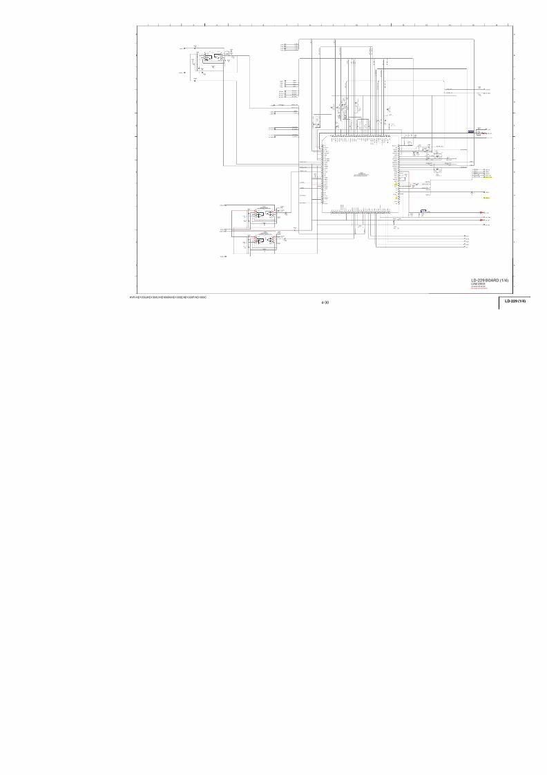
7/18/2019 SONY+HVR-HD1000 SERVICE MANUAL
http://slidepdf.com/reader/full/sonyhvr-hd1000-service-manual 66/425
4-18
HVR-HD1000J/HD1000U/HD1000N/HD1000E/HD1000P/HD1000C
EP_XHD
XSYS_RST
EP_XVD
1.2
1.4
2.6
2.6
2.8
2.8
0.1
2.8
2 . 8
2 . 8
1 . 4
1 . 4
0
0 . 2
2 . 8 2.5
2.5
4.6
2.5
2.5
2.5
0
2.8
1.4
1 . 3
2 . 8
1 . 6
1 . 6
1 . 6
1 . 3
1 . 4
3 . 7
1 . 8
2 . 3
1.6
1.10.6
1.1
0.5
3 6 9
B
7
C
8
D
G
E
H
1 4
A
2 5
F
C37132.2u
B
C37020.1u B C3706
560p CH
C370810u
B
C37104.7u
B
C37152.2u
B
C371410u B
C3716
0.1uB
C3711XX
C37011uB
C37124.7u B
C370722u4V
A_4.6V
EVRE
N_8.5V
VD_SO
XCS_EVF
REG_GND
XVD_SCK
EVGR
EVF_OUT_EN
EVBL
A_2.8V
VD_SI
FB3701
CL3705
CL3704
CL3703
CL3702
CL3701
CL3706
L370210uH
L370310uH
L370110uH
R3705100k
±0.5%
R370168k
R3 70 2 47 0
R3706
XX
R370710k
IC3701CXM3018R-T4
1 2 3 4 5 6 7 8 9 10 11 12
1 3
1 4
1 5
1 6
1 7
1 8
1 9
2 0
2 1
2 2
2 3
2 4
252627282930313233343536
3 7
3 8
3 9
4 0
4 1
4 2
4 3
4 4
4 5
4 6
4 7
4 8
Q3701
TRANSISTORHN1B04FE-Y/GR(TPLR3)3
5
4 6
2
1
R3713 XX
R3714 XX
R3715 XX
R3716 XX
R3717 XX
R371282
±0.5%
C3703 0.01u
C3704 0.01u
C3705 0.01u
R37082200±0.5%
R37091500±0.5%
RB3701
10
R 3 7 1 1
2 2 0 0
SCAN
VG
SO
E N
VSS
OPIN
V S S
V C C 1
XSTBY_P
GND1
X C L R
E X T D A
XSCK
F i l t e r
VDD
SI
GND2
C O M
_ P A N E L
XCS
XHD
VR
R I N
C O M R E F
R E F
X V D
TRST
VST
B I N
H C K 1
VCK
VDD
VP
H S T
VB
VCC2
H C K 2
X S T B Y
_ E
P O F F
R G T
WIDE
P C G
G I N
OPOUT
TEST
C O M D A
_ P A N E L
C O M D A
_ E V F
C O M
_ E V F
D W N
EVF DRIVER
EVF BACKLIGHT DRIVE
05
1 23 45 67 8
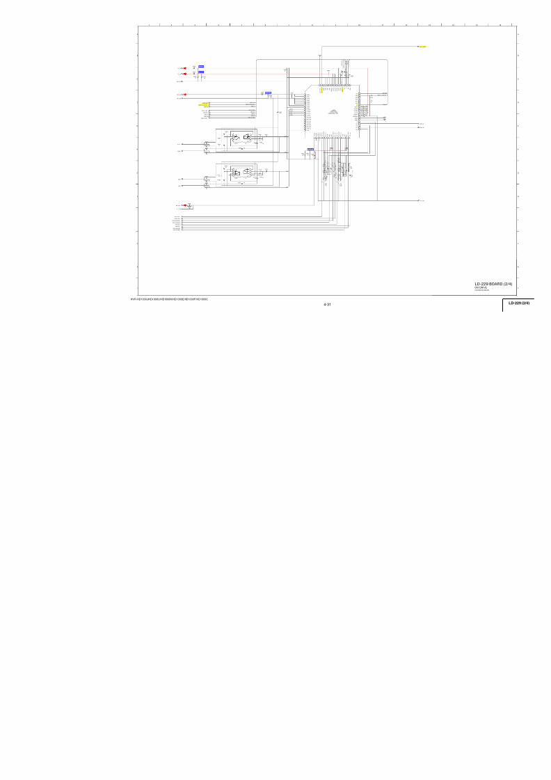
7/18/2019 SONY+HVR-HD1000 SERVICE MANUAL
http://slidepdf.com/reader/full/sonyhvr-hd1000-service-manual 67/425
4-19
HVR-HD1000J/HD1000U/HD1000N/HD1000E/HD1000P/HD1000C
4.62.3
2.3 2.3
4.6 2.8
0 . 3
2 . 3
2 . 3
2 . 3
0 2.3 2.3
2.3
3 6 9
B
7
C
8
D
G
E
H
1 4
A
2 5
F
C2912XX
C290310uB
C2920 XX
C29110.1u B
C2919
XX
C2907XX
C2908 XX
C2901XX
C2914 XX
C2909 XX
C2913XX
C2916 0.1u
B
C2915 XX
C29100.1u
B
C2904 0.1uB
C2902 XX
C2905
10u
B
C2906XX
INT_MIC_PREOUT_R
REG_GND
REG_GND
REG_GND
ZOOM_MIC_CONT
SUB/INT_CTRL
AU_2.8V
REG_GND
SHOE_MIC_FL
INT_MIC_PREOUT_L
SHOE_MIC_FR
IC2901BH7875GLU-E2
A1 B1 C1 C2 D1 D2 E1 E2 F1 F2 G1 G2
H 1
H 2
H 3
G 3
H 4
G 4
H 5
G 5
H 6 G 6 H 7 G 7
H8G8F8F7E8E7D8D7C8C7B8B7
A 8
A 7
A 6
B 6
A 5
B 5
A 4
B 4
A 3
B 3
A 2
B 2 CL2901L2901100uH
R2905XX
R2903XX
R2902XX
R2915XX
R2901XX
R2909XX
R2910XX
R2916XX
R290410k
R2919
XX
R2918XX
R2907XX
R2908XX
R29200
R29210
C2921
XX
C2922
XX
C291822u
C
R29171kC2917
22u6.3V
R291333k
R2914 220k
R2906 68k
R29226800
1/16W ±5%
R 2 9 2 4
1 k
± 5 %
C29260.1u
B
EXT_IN_L
C2924100pCH
C2923100p
CH
C29250.1u
B
R292568001/16W±5%
R 2 9 2 3
1 k 1 / 1 6 W
± 5 %
EXT_IN_R
REG_GND
REG_GND
R2928
47k
C29291uB
C293210u6.3V
C29281uB
C292710u6.3V
IC2902DS1801E-02V+T/R
1
G N D
2
C o u t
3
X R S T
4
X Z C E N
5
W 0
6
L 0
7
H 0
8
W 1
9
L 1
10
H 1
11
A G N D
12
D
13
C L K
14
V C C
R2926XX
C29300.1u
B
IC2903NJM2107F-TE2
1
2
3 4
5
R292747k
C293122u4V
R 2 9 3 5
X X
R 2 9 3 6
X X
C2937XX
R 2 9 3 8
X X
R 2 9 3 7
X X
C2938XX
R2939XX
R2940XX
MIC_IN
XMIC_MONO
C2939XX
R2941XX
R2942XX
R2943 XX
R 2 9 4 4
X X
R29450
R 2 9 4 6
X X
R29110
R2912 0
Vcc R
I N V T
_ O U T
_ L
E X T
_ I N
_ R
Vcc L
6 d B
_ O U T
_ L
M O D E
_ C T L
_ 1
BG
P R E
_ O U T
_ R
RIPL
O U T
_ A M P
_ I N
_ R
I N V T
_ O U T
_ R
H P F
_ O U T
_ L
6 d B O U T
_ R
M T X
_ I N
_ R
I N T
_ I N
_ L
M T X
_ O U T
_ R
S U B
_ I N
_ L
B L
_ O U T
_ R
GND
N C
ZOOM_AMP_OUT
SUB/INT CTRL
R_OUT
ZOOM_AMP_IN
R E G
_ 2
. 5 V
MIC_MONO
MIX_OUT
E X T
_ I N
_ L
L_OUT
GND
M O D E
_ C T L
_ 2
ZOOM_BAL
I N T
_ I N
_ R
O U T
_ A M P
_ I N
_ L
ZOOM_POSI
SUB_IN_R
M T X
__
O U T
_ L
VCC SUB
BIAS SUB
P R E
_ O U T
_ L
MIC_IN
GND
M T X
_ I N
_ L
R E G
_ 2
. 5 V
NC
NC
BIAS PRE
BIAS OUT
V-
- OUT
+
(GND)
V+
2.8V
MIC AMP
VOLTAGE FOLLOWER
MIC LEVEL CONTROL
05
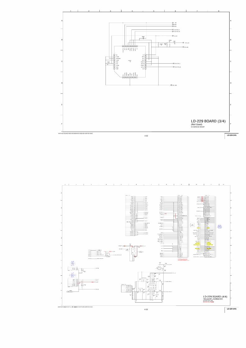
7/18/2019 SONY+HVR-HD1000 SERVICE MANUAL
http://slidepdf.com/reader/full/sonyhvr-hd1000-service-manual 68/425
4-20
HVR-HD1000J/HD1000U/HD1000N/HD1000E/HD1000P/HD1000C
A_2.8V
A_
4 . 6
V
AU_4.6V
D_2.8V
AU_2.8V
:NTSC:PAL
5.15.1
4.2 3 . 8
3.33.8
-0.3
0 0
-0.3
00
- 0 . 3
3 6 9
B
7
C
8
D
G
E
H
1 4
A
2 5
F
C 3030 4.7u B
C 3028 1u B
C30120.01u
B
C 3 0 1 4
0 . 1
u
B
C3007
10u B
C3003 10uB
C30114.7u
B
C 3 0 3 9
1 u B
C 3 0 2 1
4 . 7
u
B
C300510u
B6.3V
C3008 2.2u
B
C 3 0 1 8
4 . 7
u
B
C3001
0.1u B
C30411uB
C3023 0.1u B
C30150.1u
B
C30420.1u B
C30361uB
C3031 1u B
C3025 1u B
C30092.2u
B
C30331u
B
C3024 1u B
C3004 10u
B
C3027 0.1u B
C3026 0.1u B
C301610uB
C 3 0 4 0
1 u B
C 3 0 1 9
4 . 7
u
B
C30170.01u
B
C3032 1u B
C300610u B
C 3 0 2 2
0 . 1
u
B
C30201u B
C3029 1u B
C3002
0 .1u B
C30354.7u
B
AUDIO_R_I/O
LINE_OUT_Y
MT_5V
REG_GND
AUDIO_L_I/O
A U
_ 2
. 8 V
AU_4.6V
VIDEO_I/O
S_Y_I/O
KASYAON R E G
_ G N D
D_2.8V
A_4.6V
A_2.8V
R E G
_ G N D
LINE_OUT_C/PB
BEEP
S_C_I/O
R E G
_ G N D
V O L O U T
_ R
V O L O U T
_ L
XVSP_SCK
XCS_IC_3001
VSP_SO
SP+
SP-
FB3001
1
V C C D R I V E
2
V M I X
_ O U T
3
C_
O U T
4
S D C
_ O U T
5
V_
G N D
6
C O U T
_ I N 2
7
C O U T
_ I N 1
8
V C C H
_ V
9
Y O U T
_ I N 2
10
Y O U T
_ I N 1
11
Z A P
12
Y_
I N
13
V_
G N D
14
V_
I N
15
C L A M P
16
S D C
_ I N
17
C_
I N
18
Y_
A G C
19
Y I N
_ O U T
20
C_
A C C
21
C I N
_ O U T
22
D_
G N D
23
D A T A
2 4
CLOCK
2 5
CS
2 6
VCC_D
2 7
SDC_OUT
2 8
MIC_MONO
2 9
INT_EXT 3
0
PBIN_R
3 1
PBIN_L
3 2
GND
3 3
AGC_TC
3 4
RECOUT_R
3 5
RECOUT_L
3 6
DETHPF_R
3 7
DETHPF_L
3 8
AGC_LINK
3 9
VCC
4 0
OFFSET_L
4 1
INTLPF_R
4 2
EXTMIC_L
4 3
INTEXT_IN
4 4
EXTMIC_R
4 5
MICMONO_IN
4 6
VREF
47
M I C
_ R E G
48
M I C V C C
49
I N T L P F
_ L
50
V C C
51
I N T M I C
_ L
52
I N T M I C
_ R
53
O F F S E T
_ R
54
G N D
55
L I N E I N
_ L
56
L I N E I N
_ R
57
L I N E O U T
_ L
58
P M U T E
_ L
59
G N D
60
P M U T E
_ R
61
L I N E O U T
_ R
62
V C C H
63
V R E F H
64
O F F S E T
_ S P
65
B E E P
_ I N
66
S P
_ D R I V E
67
V C C S P
68
V R E F S P
69
N C
7 0
SPOUT+
7 1
NC
7 2
SPGND
7 3
SP_MODE
7 4
SPOUT-
7 5
HPOUT_L
7 6
GND
7 7
HPOUT_R
7 8
MUTE_OUT
7 9
VDD
8 0
C+
8 1
C-
8 2
GND
8 3
VSS_OUT
8 4
VSS_IN
8 5
VSS_IN
8
6
YLPF_OUT
8 7
YDRIVER_IN
8 8
Y_OUT
8 9
GND
9 0
V_OUT
9 1
VDRIVER_IN
9 2
NC
L300410uH
L3003
10uH
L3001 10uH
L300510uH
L300610uH
L300210uH
Q3001CPH6501-TL-E
6
2
1
3
5
4
R3014
10k
R3003100k
R3008100
R300475
R 3 0 0 9
R30163900
R300275
R3007100
R301733k
R300175
R3010100k
R301147k
R30064700
R301310k
R301247k
R3015XX
R3005
XX
R3020
10k
R301947
Q3003
RN1910FE(TPLR3)
6
2
1
3
5
4 R302110k
R301847
HP_L_OUT
HP_R_OUT
C304347u6.3V
Q3002RN1910FE(TPLR3) 6
2
1
3
5
4
C3044 47u 6.3V
C3034 10u B
C301310u B
3.3V REG
MUTE SWITCH
MUTE SWITCH
IC3001AN12921A-VBVIDEO OUT,
AUDIO IN/OUT
:NTSC:PALXX
0.01u
C3010
10kXX
R3009
05
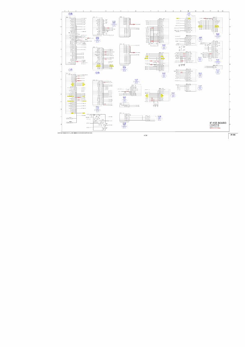
7/18/2019 SONY+HVR-HD1000 SERVICE MANUAL
http://slidepdf.com/reader/full/sonyhvr-hd1000-service-manual 69/425
4-21
HVR-HD1000J/HD1000U/HD1000N/HD1000E/HD1000P/HD1000C
R1.4/P2.5
R1.1/P4.3
4.6
R0.7/P1.8
R0.7/P1.8
0.9
1.7
1.1
R1.1/P4.3
R 2 .
8 / P 0
1 . 4
2 . 8
R 2 .
8 / P 0
2 . 8
R 2 .
8 / P 0
2 . 8
R 1 .
3 / P 0 0
R 1 .
4 / P 0
2 . 8
R1/P1.9
R1.2/P1.9
R1.2/P1.9
R1/P1.9
R1/P1.9
R1.2/P1.9
R1.2/P1.9
R1/P1.9
4 . 6
R 1
. 5 / P 0
R 1
. 5 / P 0
R 1
. 5 / P 0
4 . 6
1 . 5
1 . 1
2 2
3 6 9
B
7
C
8
D
G
E
H
1 4
A
2 5
F
RECA1
RECA2
RECDT
RECCK
R E C D T
R E C A 2
R E C A 1
R E C C K
C49130.1u
B
C4907 0.47u B
C 4 9 1 2
0 . 1
u B
C49060 .1 u B
C49040.1u
B
C4908 0.01u
B
C49050.47u
B
C49150 .1 u B
C49010.01u B
C 4 9 0 9
0 . 0
1 u
B
C 4 9 1 1
0 . 1
u
B C 4 9 1 0
0 . 1
u B
CN4901 10P
1 G ND
2 XEVEN
3 YEVEN
4 G ND
5 Y ODD
6 X ODD
7 G ND
8 X SDL
9 Y SDL
10 GND
RECDT
ALL_PS
RECA2
A_2.8V
SW_PS
REG_GND
RECA1
RECCK
SWP
CONT1
RP_4.6V
RF_MON
RFIN
IC4901TLS26A102PFBR
1
2
3
4
5
6
7
8
9
1 0
1 1
1 2
131415161718192021222324
2 5
2 6
2 7
2 8
2 9
3 0
3 1
3 2
3 3
3 4
3 5
3 6
37 38 39 40 41 42 43 44 45 46 47 48
L4902
10uH
L4901
10uH
R 4 9 0 9
2 2 k
± 0
. 5 %
R 4 9 1 0
1 0 k
± 0
. 5 %
R4916 180
±0.5%
R 4 9 0 7
1 0 k
R4917 180
±0.5%
R 4 9 1 1
1 0 k
± 0
. 5 %
R 4 9 1 3
2 2 k
± 0
. 5 %
R 4 9 0 8
6 8 0 0
R4904 22k
R4903 10k
R4914 180
±0.5%
R4915 180
±0.5%
C490210uB
C490310u
B
R4918XX
R E C
_ D A T A
X M E / M P
TEST_OUT
R E C
_ I R
_ M E
PB_RF_IN
M O D E 2
A_2.8V
D2O
XO
V C C
_ H E A D
GND
AGC_EVR
GND
R E C
_ A 2
RP_4.6V
D2E
PB_RF_OUT
R E C
_ P E A K
_ I_ M E
V C C
_ R E C
_ 4
. 6 V
P B
_ I R
R E C
_ A 1
R E C
_ C L K
R E C
_ I R
_ M P
D8 75Hz
C E
V C C
_ D 2
. 8 V
75Hz RF SWP
D1E
GND
R E C
_ P E A K
_ I_ M P
P B
_ F B D P
C T R L 1
GND
AGCTC_Ech
C O
M O D E 1
T E S T
C T R L 0
XE
PB_X_OUT
LPF_f0
AGCTC_Och
PB_Y_OUT
V C C
_ 2
. 8 V
YE
VCC_PB_4.6V
YO
S W
_ P S
R E C
_ P E A K
_ T
D1O
GND
GNDREC/PB AMP
05
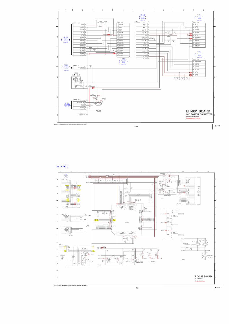
7/18/2019 SONY+HVR-HD1000 SERVICE MANUAL
http://slidepdf.com/reader/full/sonyhvr-hd1000-service-manual 70/425
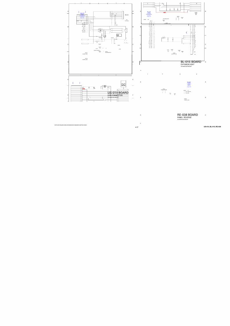
7/18/2019 SONY+HVR-HD1000 SERVICE MANUAL
http://slidepdf.com/reader/full/sonyhvr-hd1000-service-manual 71/425
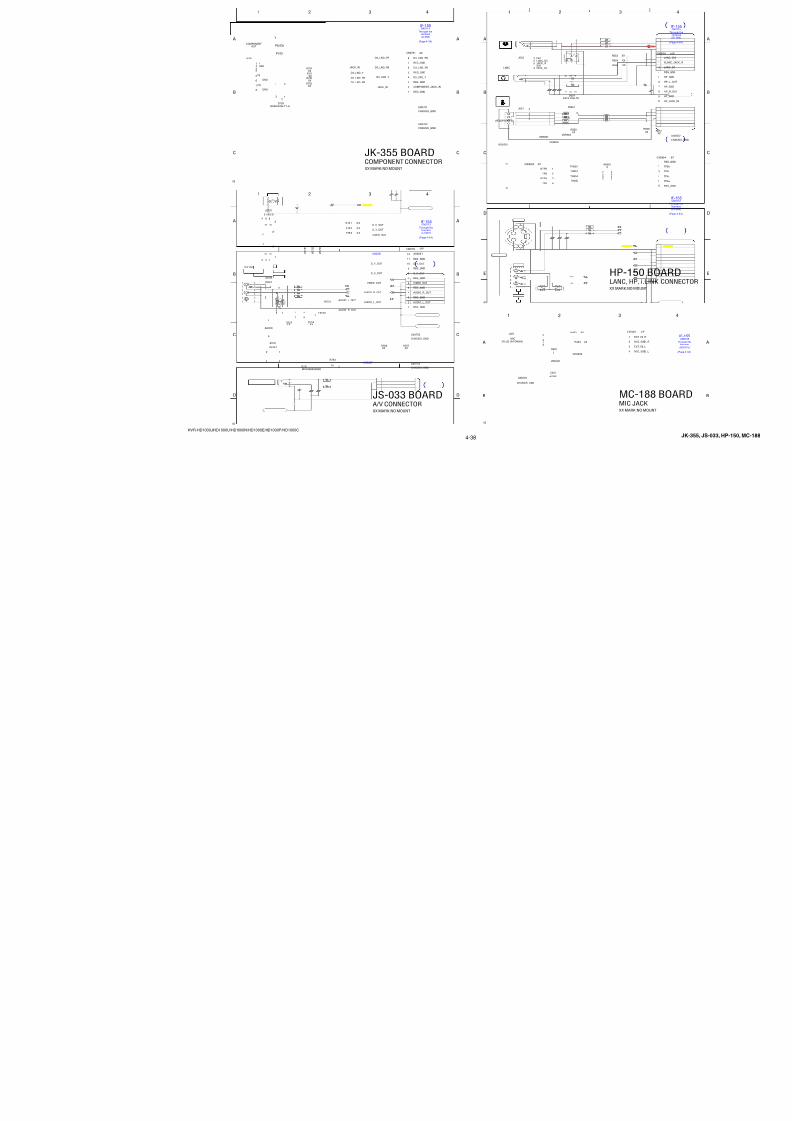
7/18/2019 SONY+HVR-HD1000 SERVICE MANUAL
http://slidepdf.com/reader/full/sonyhvr-hd1000-service-manual 72/425
4-24
HVR-HD1000J/HD1000U/HD1000N/HD1000E/HD1000P/HD1000C
D_2.8V
Note:IC5202 is not supplied, but included in VC-500 complet
3 6 9
B
7
C
8
D
G
E
H
1 4
A
2 5
F
D5_VM
D15_VM
A6_VM
A2_VM
A5_VM
A3_VM
WE0_VM
D14_VM
D2_VM
D1_VM
A10_VM
D11_VM
A8_VM
D8_VM
A13_VM
A4_VM
XCAS_VM
A12_VM
D4_VM
D10_VM
CKE_VM
XWR_VM
A1_VM
D3_VM
D12_VM
A14_VM
D0_VM
A11_VM
DSCK_VM
D13_VM
D9_VM
D6_VM
XCS_SDRAM_VM
XWE1_VM
A7_VM
XRAS_VM
A9_VM
D7_VM
A20_VM
A16_VM
A 1 9
_ V M
XBS_VM
X C S
_ F L A S H
_ U T A
A12_VM
A4_VM
A 6
_ V M
D5_VM
A19_VM
A 1 7
_ V M
X W A I T
_ V M
A14_VM
A 5
_ V M
A18_VM
D 6
_ V M
D 1 3
_ V M
A5_VM
D12_VM
D2_VM
A20_VMA9_VM
A15_VM
D 1 2
_ V M
A 3
_ V M
A1_VM
A9_VM
D7_VM
A8_VM
A17_VM
A13_VM
A7_VM
D9_VM
A6_VM
A 7
_ V M
A14_VM
D11_VM
D13_VM
A15_VM
D 7
_ V M
D8_VM D 1 4
_ V M
D14_VM
A 1 8
_ V M
D3_VM
A11_VM
A16_VM
XWE1_VM
A13_VM
A 8
_ V M
A3_VM
A21_VM
D10_VM
A10_VM
D15_VM
D6_VM
DSCK_VM
A11_VM
D S C K
_ V M
D 1 5
_ V M
A12_VM
A10_VM
X B S
_ V M
A21_VM
D 5
_ V M
D1_VM
D4_VM
D0_VM
A 4
_ V M
A2_VM
XSYS_RST
D11_VM
A7_VM
WE0_VM
A13_VM
CKE_VM
XWR_VM
D13_VM D2_VM
D3_VM
XCAS_VM
D4_VM
A5_VM
D5_VM
D12_VM
A9_VM
A4_VM
A10_VM
XCS_SDRAM_VM
D1_VM
XWE1_VM
A6_VM A3_VM
D8_VM
D14_VM
A8_VM
D15_VM
XRAS_VM
A11_VM
D6_VM
D7_VM
D9_VM
A1_VM
D10_VM
A2_VM
D0_VM
DSCK_VM
C52090.01u
B
C52061uB
C520322u
6.3VTA
A10_VM
XWE1_VM
A5_VM
D7_VM
A7_VM
D15_VM
WE0_VM
D10_VM
XWR_VM
D1_VM
A4_VM
D_2.8V
D5_VM
D2_VM
REG_GND
D14_VM
D4_VM
XCS_SDRAM_VM
D0_VM
D3_VM
A1_VM
XBS_VM
A9_VM
A1_VM
A8_VM
XCAS_VM
CKE_VM
A6_VM
A12_VM
D9_VM
D2_VM
D12_VM
D6_VM XRAS_VM
A14_VM
05
D11_VM
A13_VM
D8_VM
DSCK_VM
A3_VM
A11_VM
DSCK_VM
D13_VM
A11_VM
A18_VM
A21_VM
A20_VM
A3_VM
A14_VM
D5_VM
A10_VM
D13_VM
A19_VM
A8_VM
D4_VM
D3_VM
D12_VM
D14_VM
D10_VM
D6_VM
A5_VM
A4_VM
D8_VM
A6_VM
A12_VM
A17_VM
A16_VM
A13_VM
A2_VM
D7_VM
A9_VM
A7_VM
D11_VM
D15_VM
A2_VM
D9_VM
D0_VM
D1_VM
A15_VM
FB5201
IC5202S99-50031-33-ER
1 VSS
2 A15
3 A14
4 A13
5 A12
6 A11
7 A10
8 A9
9 A8
1 0 A19
1 1 A20
1 2 XWE
1 3 XRST
1 4 NC
15
C L K
X W P
16
V C C
17
X A V D
18
X C E
19
A 1 8
20
A 1 7
21
A 7
22
A 6
23
A 5
24
A 4
25
A 3
26
A 2
2
D Q 1 2
4
D Q 5
45
D Q 1 3
46
V S S Q
47
V C C Q
48
D Q 6
49
D Q 1 4
50
D Q 7
51
D Q 1 5
52
R D Y
53
N C
54
A 1 6
55
V C C
56
R52041k
R5203XX
C5202
0 .1u C
IC5201W9816G6CB-7-ER20
1VDD
2DQ0
3DQ1
4VssQ
5DQ2
6DQ3
7VDDQ
8DQ4
9DQ5
1 0VssQ
1
1DQ6
1 2DQ7
1 3VDDQ
1 4LDQM
1 5XWE
1 6XCAS
1 7XRAS
1 8XCS
1 9BA
2 0A10
2 1A0
2 2A1
2 3A2
2 4A3
2 5VDD 2
6 Vss
2 7 A4
2 8 A5
2 9 A6
3 0 A7
3 1 A8
3 2 A9
3 3 NC
3 4 CKE
3 5 CLK
3 6 UDQM
3 7 NC
3 8 VDDQ
3 9 DQ8 4
0 DQ9
4 1 VssQ
4 2 DQ10
4 3 DQ11
4 4 VDDQ
4 5 DQ12
4 6 DQ13
4 7 VssQ
4 8 DQ14
4 9 DQ15
5 0 Vss
C52010.1u
C
1.8V
D_2.8V
1.8V
16M SDRAM
32M FLASH
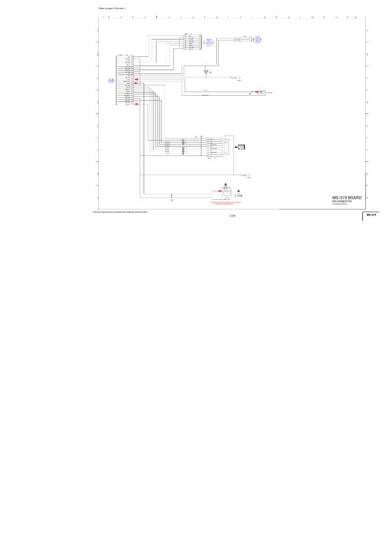
7/18/2019 SONY+HVR-HD1000 SERVICE MANUAL
http://slidepdf.com/reader/full/sonyhvr-hd1000-service-manual 73/425
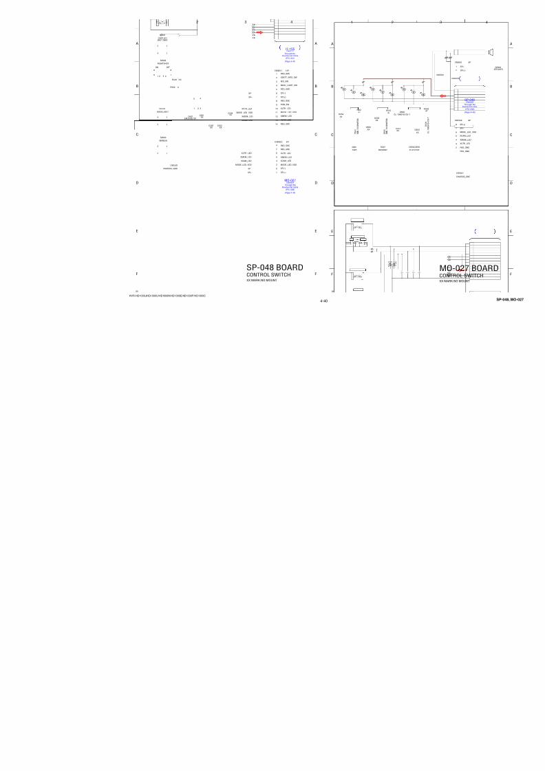
7/18/2019 SONY+HVR-HD1000 SERVICE MANUAL
http://slidepdf.com/reader/full/sonyhvr-hd1000-service-manual 74/425
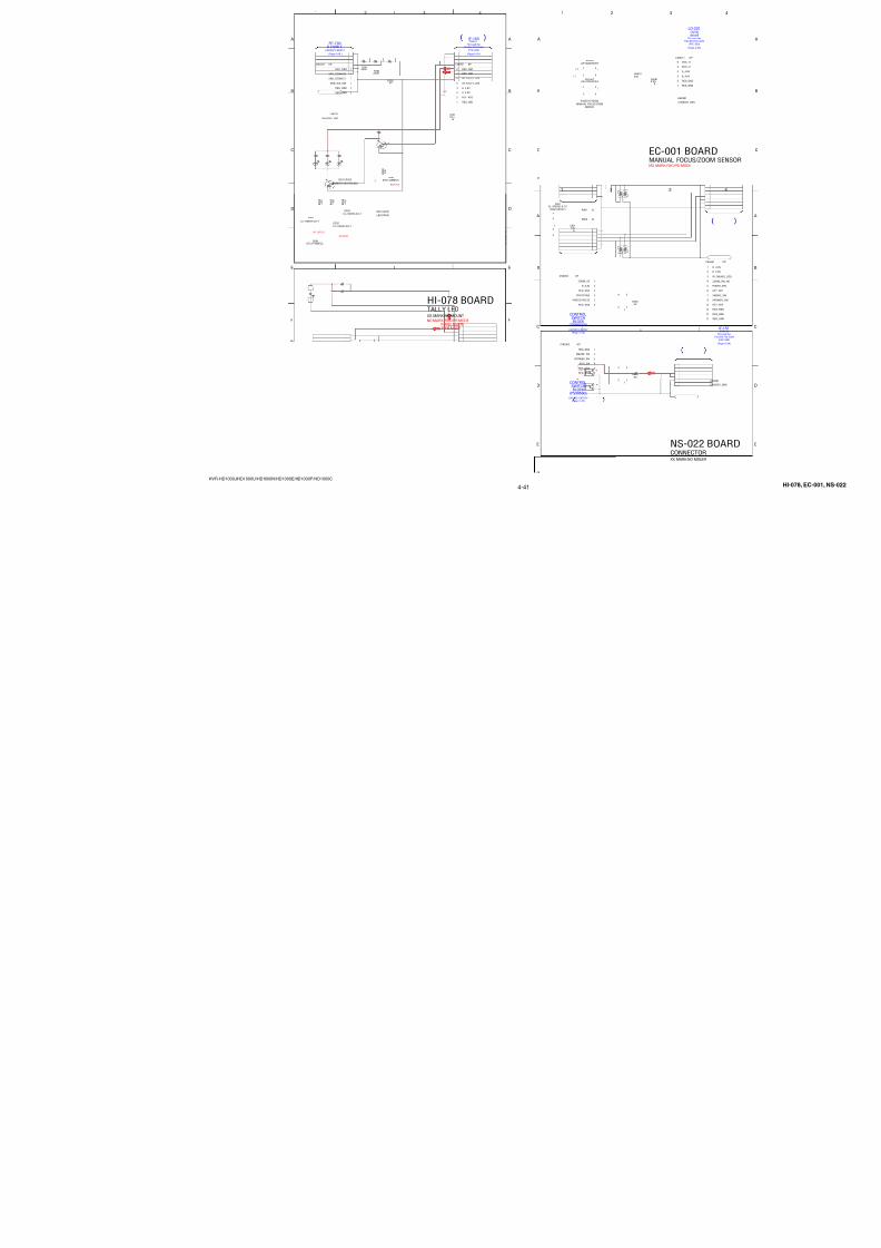
7/18/2019 SONY+HVR-HD1000 SERVICE MANUAL
http://slidepdf.com/reader/full/sonyhvr-hd1000-service-manual 75/425
4-27
HVR-HD1000J/HD1000U/HD1000N/HD1000E/HD1000P/HD1000C
VOUT
XPOWER_SW
XMODE_SW
D_2.8V
:PAL:NTSC
:PAL:NTSC
3 6 9
B
7
C
8
D
G
E
H
1 4
A
2 5
F
IC_5001_RXD0
X V T R_
L E D_
O N
R E S E T_
A D
XLANC_PWR_ON
SYS_V
INIT_CHARGE_ON
MULTI_JACK_IN
X R E S E T
VTR_DD_ON
VTR_UNREG
L A N C_
O U T
MULTI_JACK_IN
X P O W E R_
S W
X C A M_
L E D_
O N
IC_5
XMODE_SW
IC_5
OSD_V
BATT_IN
LANC
IC_5001_CS
X C C_
D O W N
FR_EVER_SO
IC_5
X E J E C T_
S W
XCS_D
XDS
XEJECT_SW
FR_E
XLAN
XPOWER_SW
XMEM_LED_ON
SYS_V
IC_5
IC_5001_TXD0
XLANC_ON
XCAM_LED_ON
XVTR_LED_ON
FAST
OSD
LANC
X B A T T_
I N F O_
S W
XRES
XCHARGE_LED_ON
FR_EVER_SCK
XLAN
XVM
BATT
BATT
BATT_
XBATT_INFO_SW
BATT_UNREG
X M O D E_
S W
X C H A R G E_
L E D_
O N
IC_5001_SCK0
FAST_CHARGE
FR_E
XCC_
INIT_
XSYS_
VTR_D
X M E M_
L E D_
O N
SHOE
XLAN
XF_TALLY_LED
S H O E_
O N
X F_
T A L L Y_
L E D
XFIR
BATT/XEXT
XVM_MAD
XFIRMUP
B A T T_
S I G
B A T T_
S I G
XDS_RESET
XSYS_RST
XCS_DD
X L A N C_
J A C K_
I N
EVER_3.0V
L A N C_
I N
D_2.8V
R50231M
R5024
470
R 5
0 3 9
BATT_UNREG
R50461M
±0.5%
C501522u
6.3VTA
R5047470k±0.5%
XBATT_INFO_SW
CL5006
R500847k
RB50061k
R 5 0 3 7
D_2.8V
R501610M
XCHARGE_LED_ON
C 5 0 1 2
0 . 0
1 u
B
RB5005
100k 1
2
3
4
5
6
7
8
VOUT
XMEM_LED_ON
C50100.1u B
K2
R S T x
K1
M O D
K3
T M D
L2
X 0 A
L3
X 1 A
H1
C P O
J1
V C I
A1
B R S T X
L1
B D B M X
A11
B S I N
B9
B S O U T
C9
B S O U T
A9
B E X C K
A4
X P U D I O_
S I O_
I B
K4
S U B C K
L4
S U B C K
L10
A V C C
L9
A V S S
K10
A V R
B4
X P U I_ P O W E R_
V T R_
S W
A3
X P U I_ M O D E_
C A M_
S W
B3
X P U I_ E J E C T_
S W
A2
X P U I_ C C D O W N_
S W
B2
X P U I_ B A T T I N F O_
S W
B 1XI_LANC
POWER_ON
C 2O_FAST
CHARGE
C 1O_INITCHARGE
C 3I_CHARGEINH
D 2
O_SO_DO
D 1
XO_SCK_DD
D 3
XO_TOHIV_OUT
E 3O_VTRDDON
E 1PUI_P15
E 2PUI_P16
F 1PUI_P17
F 2XI_HIFIRMUP
G 1
XI_HIMAD
G 2
PUI_BATT_XEXT_CRA
H 2
PUI_BATT_XEXT
H 3
XO_CS_HI
J 4I_SI_HI
L 5O_SO_HI
K 5
XO_SCK_HI
J 5AI_MULTIJACKCRA
L 6AI_MULTIJACK
K 6
AI_BATTSENSE
J 7AI_ACVSENSE
L 7AI_DDSEL
K7
A I_ S Y S T E M S E L
L8
X I_ L A N C J A C K I N
K8
O_
P U L L U P S E L
K11
A I_ K E Y A D 0
K9
A I_ K E Y A D 1
J10
A I_ K E Y A D 2
J11
A I_ K E Y A D 3
H9
A I_ D D S E L 2
H10
A I_ S Y S T E M S E L 2
H11
A I_ T P X
G10
A I_ T P Y
G11
X O_
C H A R G E L E D
F11
X O_
C A M L E D
F10
X O_
M E M L E D
E11
X O_
P L A Y L E D
E10
X O_
F T A L L Y L E D
E9
O_
G P 5 5
D11
O_
G P 5 6
D10
O_
S H O E_
O N
D9
O_
T P S E L 1
C11
O_
T P S E L 2
C10
O_
S O_
L A N C
B10
I_ S I_ L A N C
B8
O D O_
N T S C
/ P A L D E T
A 8
XODO_SYSRST
C 8
XO_HIRST
B 7
O_P67
A 7
I_BATTIN
C 7
XI_SYSV
B 6
XPUI_MEM_SW
A 6
XO_CS_DD
C 5
XO_CS_DD2
B 5
XO_LANCON
A 5
O_SO_IB
C 4
I_SI_IB
B 1 1
VCC1
J 2 VCC2
A 1 0
VSS1
C 6
VSS2
F 3 VSS3
F 9 VSS4
G 3
VSS5
G 9
VSS6
J 6 VSS7
J 8 VSS8
J 9 VSS9
J 3 NC
L 1 1
NC
C501112pCH
C50070.01u B
Q5002XX
C50050.01u B
XEJECT_SW
C 5 0 0 4
0 . 0
1 u B
C50160.01u
B
C50170.01u
B
R B 5 0 0 1
1 k
C 5 0 1 8
0 . 1 u B
RB50071k
R 5 0 0 2
1 8 0 0
± 0 . 5
% R 5 0 4 1
4 7 0 0
MULTI_JACK_IN
R504547k±0.5%
XVTR_LED_ON R 5 0 1 7 0
VTR_UNREG
C50060.1u
B
C 5 0 1 3 0 . 1 u
B
R5044100k±0.5%
D5001XX
C500810pCH
XCAM_LED_ON
R 5 0 0 1
6 8 0 0
± 0 . 5
%
REG_GND
R5026XX
XF_TALLY_LED
R5048 0
R 5 0 5 0
2 2 0
R 5 0
5 1
X
X
C L 5 0 0 9
C L 5 0 1 0
C L 5 0 1 2
C L 5 0 0 7
C L 5 0 1 1
C L 5 0 0 8
X 5 0 0
2
3 2 . 7
6 8 k
H z
CL5015
CL5016
NTSC/XPAL_DET
R 5 0 3 6
X X
R
5 0 3 8
X XR5053
100k
RB500310k
R505210k
D_2.8V
XX10k
R5037
XX10k
R5039
05
1
2
6
4
5
3
1
3
2
4
1 23 45 67 8
1
2
3
4
5
6
7
8
1 23 45 67 8
1 23 45 67 8
IC5001MB95005BGL-G-119-ERE1
HI CONTROL
Ver. 1.3 2008.12
The changed portions fromVer. 1.2 are shown in blue.
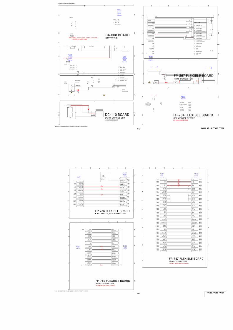
7/18/2019 SONY+HVR-HD1000 SERVICE MANUAL
http://slidepdf.com/reader/full/sonyhvr-hd1000-service-manual 76/425
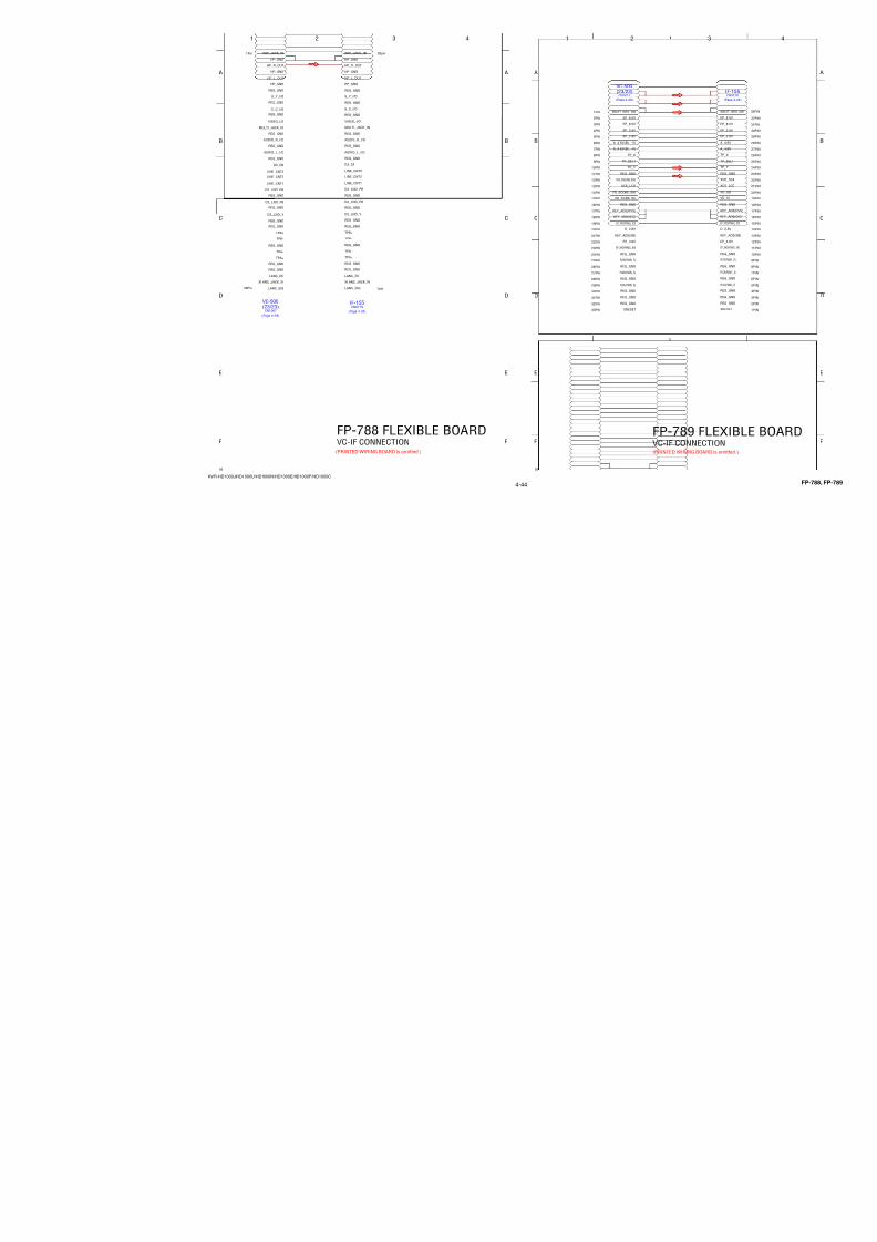
7/18/2019 SONY+HVR-HD1000 SERVICE MANUAL
http://slidepdf.com/reader/full/sonyhvr-hd1000-service-manual 77/425
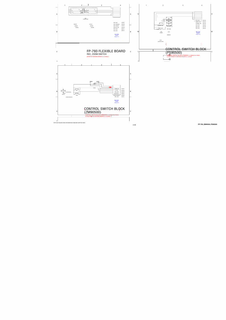
7/18/2019 SONY+HVR-HD1000 SERVICE MANUAL
http://slidepdf.com/reader/full/sonyhvr-hd1000-service-manual 78/425
4-30
HVR-HD1000J/HD1000U/HD1000N/HD1000E/HD1000P/HD1000C
D_2.8V5
2.5
2.5
2 . 5
2 . 5
2.5
2.5
5
2.5
2.5
2.5
2.5
2.5
2.5
C
9
A
I
H
5
F
3 13762
E
124
L
D
1
G
11
K
B
108
J
ND_BIAS+
F_MR_A
F_MR_B
I_ H A L L
_ A D 1
ND_HALL-
A D
_ F C
_ M R
_ B
N D
_ H A L L
_ A D 1
A D
_ F C
_ M R
_ A
ND_BIAS-
I_ H A L L
_ A D 1
A D
_ F C
_ M R
_ A
CAM_S
N D
_ H A L L +
ND_HALL+
N D
_ B I A S +
N D
_ B I A S -
I_BIAS-
I_DRIVE+
I_ B I A S +
FOCUS-_OUT
I_ B I A S -
XRST_IC_1801
CAM_SC
A D
_ Z M
_ M R
_ B
ND_DRIVE-
A D
_ Z M
_ M R
_ A
I_ H A L L -
ND_HALL-
I_HALL-
NF_DRIVE+
N F
_ D R
I V E -
I_ H A L L +
XCS_IC_1801
A D
_ F C
_ M R
_ B
NF_DRIVE-
CAM_S
N F
_ D R
I V E +
Z_MR_B
I_HALL+
Z_MR_A
ND_DRIVE+
I_BIAS+
I_DRIVE-
F_
M R
_ A
F_
M R
_ B
FOCUS+_OUT
FOCUS-_OUT
FOCUS+_OUT
ZOOM_B_OUT
I_DRIVE-
ND_DRIVE-
ND_DRIVE+
I_DRIVE+
C5401XXB
10V
C 5 4 0 9
0 . 0
0 2 2 u
B
C 5 4 1 4
0 . 1
u
B
C54110.0022u
B
C5403XX
C5402XX
C 5 4 1 5
0 . 1
u
B
C5427
330p SL
C541247pCH
C54230.1u
B
C54100.1u
B
C5430
0.22u
C54250.1u
B
C5420
XX B
C 5 4 1 7
0 . 1
u
B
C54220.1u B
C5416
0 .1 u B
C5419
0 .1u B
C 5 4 1 8
X X
B
C54240.1uB
C5431
0.1u B
C54060.068u
B
C5404XX
B1005
C54050.068u
B
C5428
22u6.3V
C5421
22u 10V
C543222u
6.3V
F_MR_B
Z_MR_A
F_MR_A
I_HALL+
ND_HALL+
ND_HALL-
Z_MR_B
ND_DRIVE-
FOCUS-
ZOOM_XA
I_BIAS+
I_DRIVE-
ND_BIAS-
NF_DRIVE+
I_BIAS-
ZOOM_XB
FOCUS-
FOCUS+
NF_DRIVE-
ZOOM_B
ZOOM_A
ND_BIAS+
FB5
IC5402NJM3414AV(TE2)
1
2
3
4GND
5
6
7
8 VCC
IC5403NJM3414AV(TE2)
1
2
3
4GND
5
6
7
8 VCC
IC5401XX
1
2
3
4GND
5
6
7
8 VCC
IC5404BU2343GLU-E2
A 1
C 3
D 3
B 1
C 2
E 4
C 1
D 2
D 1
E 3
E 2
E 1
F 3
F 2
F 1
F 4
G 4
G 1
G 2
G 3
H 1
H 2
H 3
J 1
J 2
K 1
H 4
K 2
L 1
J 3
J 4
L 2
M1 K3 K4 M2 L3 J5 M3 L4 M4 K5 L5 M5 K6 L6 M6 J6 J7 M7 L7 K7 M8 L8 K8 M9 L9 M10 J8 L10 M11 K9 J9 L11
M 1 2 K 1 0 J 1 0 L 1 2 K 1 1
H 9 K 1 2 J 1 1 J 1 2 H 1 0 H 1 1 H 1 2 G 1 0 G 1 1 G 1 2 G 9
F 9
F 1 2 F 1 1 F 1 0 E 1 2 E 1 1 E 1 0 D 1 2 D 1 1 C 1 2
E 9 C 1 1 B 1 2 D 1 0
D 9 B 1 1
A12C10C9A11B10D8A10B9A9C8B8A8C7B7A7D7D6A6B6C6A5B5C5A4B4A3D5B3A2C4D4B2
L 54 0 1 1 0u H
R54530
R5440180k±0.5%
R 5 4 3 6
R 5 4 3 5
2 7 0 0
± 0
. 5 %
R5 42 7 0
R 5 4 4 5
8 2 0 0 ± 0
. 5 %
R54060
R543839k
±0.5%
R5405XX
R 5 4 4 3
2 2 0 k 0
. 5 %
R5454180k ±
R 5 4 4 1
3 3 0
± 0
. 5 %
R5456
8200
R5402XX
R5401XX
R5455
6800
R 5 4 4 6 8 2 0 0 ± 0
. 5 %
R 5 4 4 8
0
R 5 4 4 4
1 0 k
± 0
. 5 %
R5452 10k
R 5 4 3 4
3 9 k
± 0
. 5 %
R5
R 5 4 4 2 1 k
R 5 4 4 7
0
R 5 4 4 9
1 0 k
± 0
. 5 %
R 5 4 3 7
8 2 0 0
± 0
. 5 %
R 5 4 3 9
6 8 0 0
± 0
. 5 %
R54320
R5457
R5450
220k±0.5%
R 5 4 3 3
8 2 0 0
± 0
. 5 %
2 7 0 0
± 0
. 5 %
R541110k
R543010k
R543110k
R5421
10k
R5404XX
R5415XX
R5420XX
R5403XX
R5409
XX
R5410XX
R5422
10k
R542510k
R541310k R5426
10k
R541410k
R542310k
R541210k
R542410k
I_DRIVE+
ND_DRIVE+
C 5 4 1 3
1 u
B
1 6 0 8
NC
O U T 4 B
N C
N C
AVDD
E N 5
TEST2
MGND2
ND_HALL+
OUT0B
N C
I_ B I A S +
N C
O U T 5 B
D A C 4 O U T
M V C C 4
SI
MGND1
B R 5
N C
A D
_ N D
NC
P W M 2
N C
VD
N C
DVSS
MVCC0
N C
P W M 4
NC
M G N D 4
I_ B I A S -
TEST1
V R E F
E N 3
AVSS
DAC6OUT
N D
_ B I A S -
CLK_SEL
MVCC1
B R 4
DAC0OUT
I_ H A L L +
N D
_ B I A S +
O U T 4 A
OUT2B
DVDD
NC
OUT1B
OUT2A
RVDD
OPIN2N
OPIN3N
MVCC3
I R 5
NC
D A C 1 O U T
T E S T 4 ( O P E N )
E N 2
OUT3B
E N 4
OPOUT3
N C
O P I N 1 N
MGND0
REGOUT
A D
_ Z M
_ M R
_ A
N D
_ H A L L -
OUT1A
FC_MR_A
MGND3
CLK
O P O U T 1
EN0
O P I N 4 N
DAC3OUT
DAC2OUT
SO
A V S S
F C
_ M R
_ B
NC
M V C C 5
P W M 5
A D
_ Z M
_ M R
_ B
A D
_ F C
_ M R
_ A
MVCC2
OUT3A
OPOUT6
OUT0A
P W M 1
A D
_ I R
C R E F I N
NC
A V D D
O P O U T 4
N C
PWM0
ZM_MR_B
O U T 5 A
N C
OPOUT0
N C
A D
_ F C
_ M R
_ B
I_ H A L L -
T E S T 3 ( O P E N )
M G N D 5
O P I N 0 N
I R 7
N C
NC
ZM_MR_A
E N 1
AVSS
V R E G
_ P D W N
A V S S
OPIN6N
OPOUT2
P W M 3
CS
NC
XCLR
SCK
NC
TEST0
A
B
A
B
A
B
RST_SENS1
RST_SENS0
BR1
ZOOM MOTOR NOISE FILTER
ZOOM MOTOR NOISE FILTER
FOCUS/ZOOM/NF MOTOR DRIVE,ND FILTER DRIVE,IRIS DRIVE
05
I_HALL-
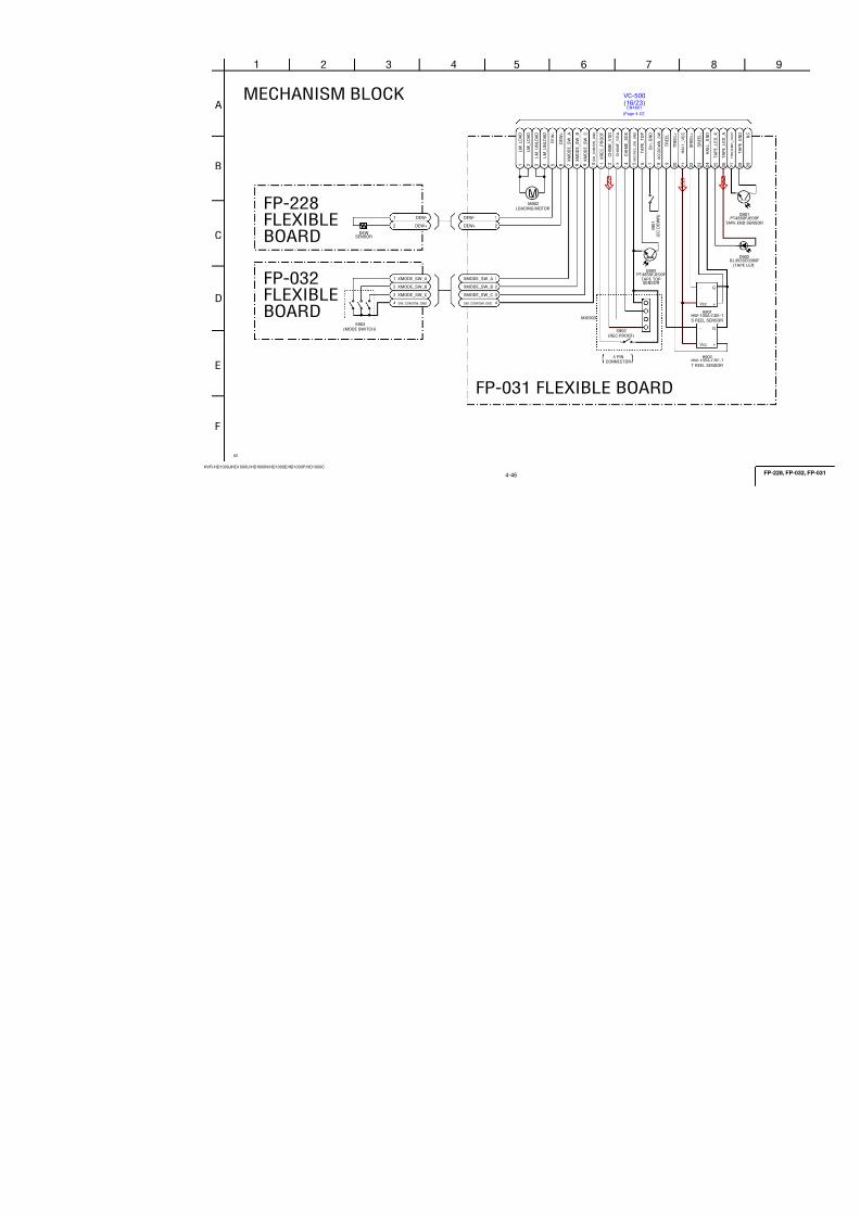
7/18/2019 SONY+HVR-HD1000 SERVICE MANUAL
http://slidepdf.com/reader/full/sonyhvr-hd1000-service-manual 79/425
4-31
HVR-HD1000J/HD1000U/HD1000N/HD1000E/HD1000P/HD1000C
D_2.8V
D_1.5V
MT_5.0V
MR_A2.8V
VST_C_RESET
XRST_IC_5703_CPU
CAM_VD
XHIDS_RST
C
9
A
I
H
5
F
3 13762
E
124
L
D
1
G
11
K
B
108
J
CAM_SI
CAM_SO
XCS_IC_1801
CAM_VD
XRST_IC_5703_CPU CAM_VD
YAW+
PITCH+
C A M
_ S I
C A M
_ S O
CAM_SCK
XHIDS_RST
YAW-
PITCH-
X H I D S
_ R S T
XRST_IC_5703_CPU
X C S
_ I C
_ 1 8 0 1
D S C K
_ I C
_ 5 7 0 3
DSCK_IC_5703
CAM_SCK
PITCH-
PITCH+
YAW+
YAW-
CAM_SO
IC5703R2J30500LG
C 1 VM5_0
C 1 0
VM5_1
A 1 PGND
E 1 PGND
A 1 0
PGND
E 1 0
PGND
F 1 DVCC
F 1 0
DGND
D 1
OUT0A
B 1 OUT0B
D 1 0
OUT1A
B 1 0
OUT1B
E 2 MD_IN0
F 2 MD_BR0
G 2
MD_EN0
E 9 MD_IN1
F 9 MD_BR1
G 9 MD_EN1
G 7 xMD_PS
V C C A 3
K1
V C C A 3
K6
G N D A 3
K7
G N D A 3
K10
O P
_ I P 0
H2
O P
_ O U T 0
J1
O P
_ I N 0
H1
D A 0
K2
I A 0
J2
I B 0
K3
O P
_ O U T 2
J3
O P
_ I N 2
J4
O P
_ I P 1
J9
O P
_ O U T 1
J10
O P
_ I N 1
H9
D A 1
K9
I A 1
J8
I B 1
K8
CH0 K 4
CH1 G 5
CH2 K 5
CH3 J 5
VB J 6
PWM2 D 4
PWM3 D 7
UDIDEBUG F 7
UDITRST E 7
UDITCK G 1
UTITMS F 4
UDITDO G 1 0
UDITDI E 4
VD C 9
PIO3 B 9
PIO2 B 8
PIO1 B 7
X S C S
A5
S O
B4
S I
A4
C L K
A3
R E S E T
_ N
A7
V C C D 3
A2
V C C D 3
A9
G N D D 3
A8
V C C D 1 5
D2
V C C D 1 5
D9
G N D D 1 5
H10
T E S T 1
B3
T E S T 2
B2
T E S T 3
C2
M A R K
E5
C P U
_ P I O
_ 0
D5
C P U
_ P I O
_ 1
D6
G 4
TEST
O P
_ O U T 3
G6
O P
_ I N 3
J7
PIO0 B 6
XDL A 6
SCK B 5
DSCK_IC_5703
C5709
XX
C57061uB
XCS_IC_1801
CAM_SI
D_2.8V
C57070.1u
REG_GND
C57081u
B
MT_GND
MT_5.0V
D_1.5V
R5704XX
R5711XX
C5701XX
R5709XX
R5707 XX
R5713XX
R5706XX
C5702XX
R5708 XX
REG_GND
L570110uH
R5703XX
R5705XX
C 5 7 1 8 X X
R 5 7 4 6 X X
R 5 7 2 1
3 9 k
± 0
. 5 % R
5 7 2 0 3
3 k ±
0 . 5
%
C 5 7 1 4 X X
R 5 7 4 1 1 2 0 k
0 . 5
% R 5 7 3 6 3 9 k
± 0
. 5 %
R 5 7 2 6
1 8 0 0
± 0
. 5 %
C 5 7 1 9
0 . 0
1 u
C 5 7 1 7
0 . 0
2 2 u
R 5 7 2 9
8 2 0 0
R 5 7 3 7
3 9 k
± 0
. 5 %
R 5 7 3 3
1 0 k
± 0
. 5 %
R 5 7 3 9
X X
R 5 7 2 5
1 2 0 k
± 0
. 5 %
C 5 7 1 6
0 . 0
0 1 u
R 5 7 4 5
8 2 0 0
R 5 7 4 2
1 8 0 0
± 0
. 5 %
C 5 7 1 5
0 . 0
1 u
C 5 7 1 3
0 . 0
0 2 2 u
B
R 5 7 4 9
1 0 k
± 0
. 5 %
R 5 7 3 0 X X
C 5 7 1 2
0 . 0
0 1 u
PITCH_HALLBIAS-
YAW_HALLBIAS-
PITCH_HALLBIAS+
YAW_HALLBIAS+
YAW_HALL-
YAW_HALL+
PITCH-
PITCH+
YAW-
YAW+
MR_A2.8V
PITCH_AD
YAW_AD
C570522u10V
R5773 100k
R5772 100k
R5771 100k
R5774 100k
R5776 100k
R5770 100k
C572222u4V
C57230.1u
B
CL5701
R5779
XX
R5780
XX
R5781
XX
R5782
XX
R5783
XX
R5784
XX
R5785
XX
R5786
XX
C5703XX
R 5 7 2 3
X X
CL5703
CL5704
R57870
R57880
R5789XX
R5790XX
PITCH_HALL-
PITCH_HALL+
R 5 7 9 1
0
R57920
R 5 7 9 3 1 0 0
C 5 7 2 4
X X
C 5 7 2 5 X X
CAM_SCK
R5714
XX
C5704XX
R5712
XX
R5710XX
R5795XX
R5796XX
A_2.8V
C 5 7 2 8
X X
C5726
XXC5727
XX
IC5701 XX
1
2
3
4 GND 5
6
7
8VCC
IC5702 XX
1
2
3
4 GND 5
6
7
8VCC
A
B
B
A
OPTICAL IMAGE
STABILIZATION DRIVE
05
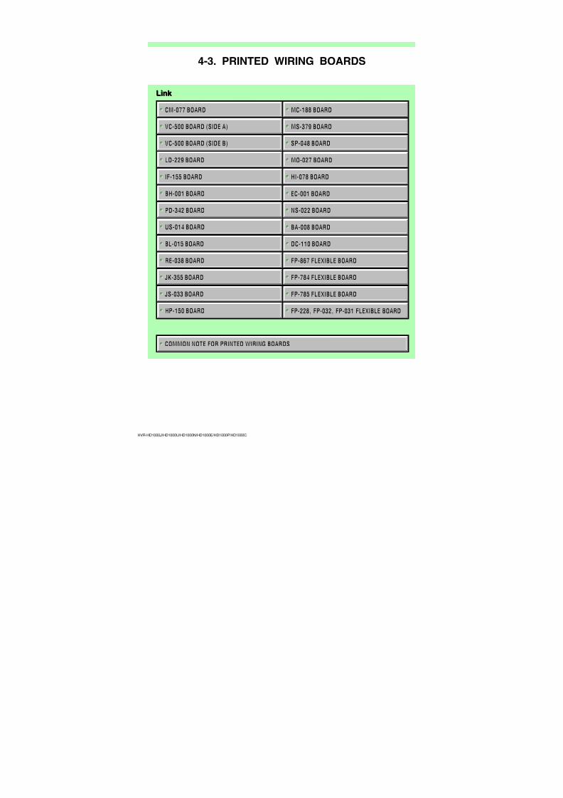
7/18/2019 SONY+HVR-HD1000 SERVICE MANUAL
http://slidepdf.com/reader/full/sonyhvr-hd1000-service-manual 80/425
4-32
HVR-HD1000J/HD1000U/HD1000N/HD1000E/HD1000P/HD1000C
D
C
6
B
A
53 4
F
2
E
1
C5801
XX
MT_GND
REG_GND
MT_5.0V
D_2.8V
EN0
DIRA0
DIRB0
SHUTTER_B
SHUTTER_XB
IC5801
XX
A1 B1 B2 C1 C2 C3 D1 D2 E1
F
1
F 2
E 2
F 3
E 3
D 3
F 4
E 4
F 5
F6E6E5D6D5D4C6C5B6
A 6
A 5
B 5
A 4
B 4
C 4
A 3
B 3
A
2
C5804
XX
SHUTTER_XA
SHUTTER_A
L5801
XXC5803XX
C5805XX
R5801XX
VREF
P G N D 2
I N 2 B
V M 2
PS
OUT1A
VM1
IN3A
I N 1 B
B R A K E 2
V M 3
R N F
I N 1 A ( E N 1 )
PGND1
O U T 3 B
S E N S E
OUT1B
P G N D 2
VLIMH
O U T 3 A
B R A K E 1
GND
IN3B
NC
O U T 2 A
VLIML
IN2A(EN2)
PGND1
O U T 2 B
N C
N C
N C
NC
VCC
VLIMS
SEL
XX
(N
L
05
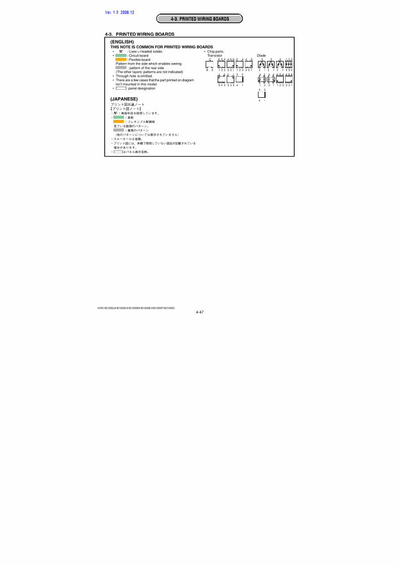
7/18/2019 SONY+HVR-HD1000 SERVICE MANUAL
http://slidepdf.com/reader/full/sonyhvr-hd1000-service-manual 81/425
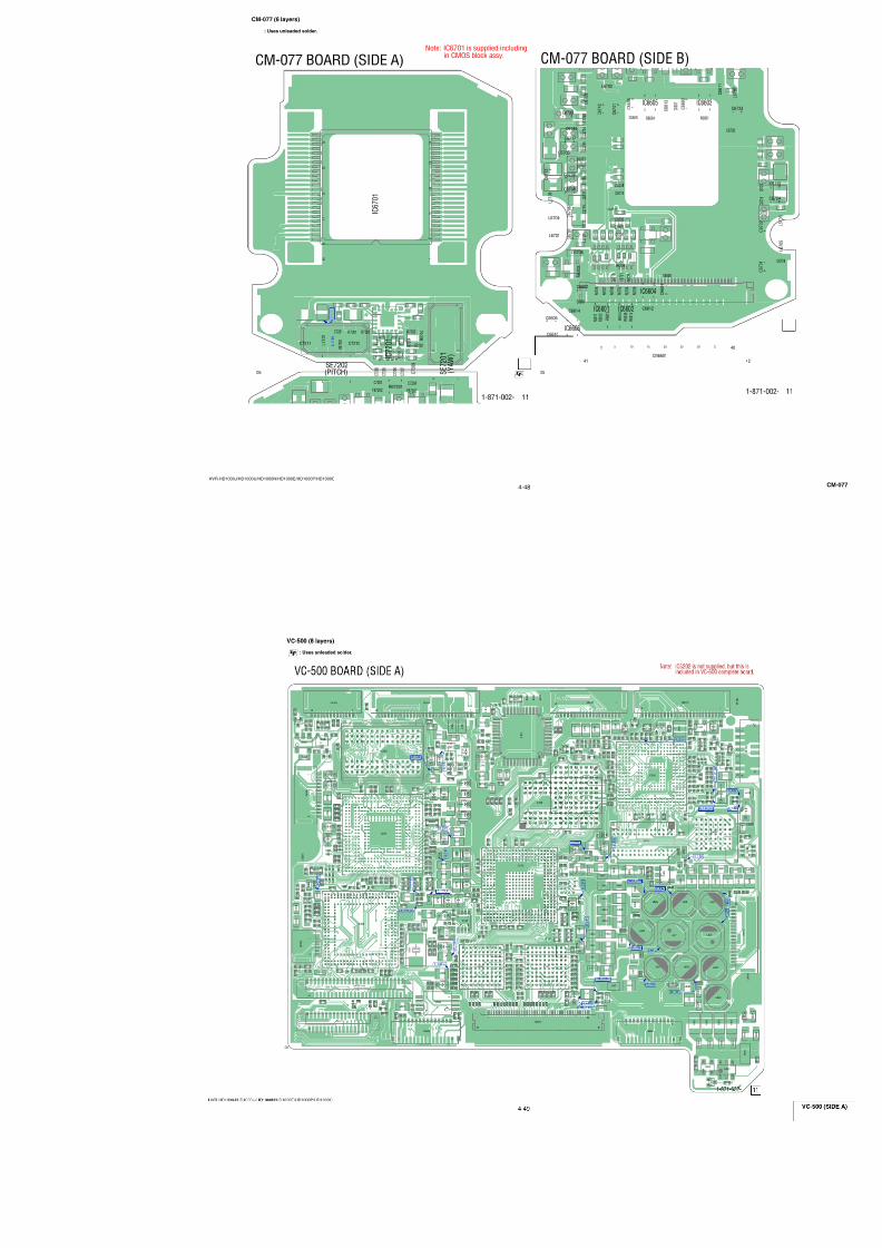
7/18/2019 SONY+HVR-HD1000 SERVICE MANUAL
http://slidepdf.com/reader/full/sonyhvr-hd1000-service-manual 82/425
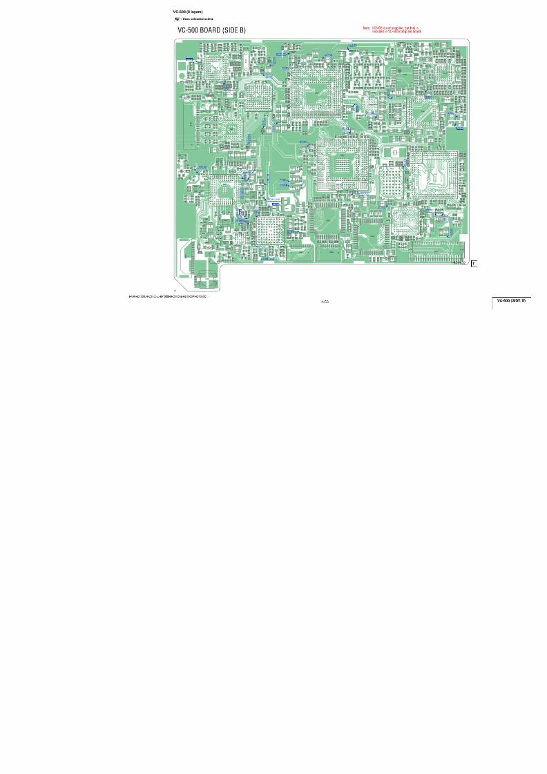
7/18/2019 SONY+HVR-HD1000 SERVICE MANUAL
http://slidepdf.com/reader/full/sonyhvr-hd1000-service-manual 83/425
4-35
HVR-HD1000J/HD1000U/HD1000N/HD1000E/HD1000P/HD1000C
RE-038
(RS-112)
(Page 4-37)
CN0851
HarnessThrough the
LND801-LND806
(Page 4-42)
FP-784FLEXIBLE
IF-155CN0103
Through the
(HP-147)
(Page 4-36)
Harness
PD-342CN6202
CN5901
Flexible Flat Cable
(FFC-338)
BL-015
Through the
(Page 4-37)
(BI-001)
(Page 4-34)
HarnessThrough the
0
2.8
2.8
2.8
0
D
C
6
B
A
53 4
F
2
E
1
CN6002 20P
1
2
3
4
5
6
7
8
9
10
11
12
13
14
15
16
17
18
19
20
CN6001 22P
1
2
3
4
5
6
7
8
9
10
11
12
13
14
15
16
17
18
19
20
21
22
C60020.1u
B
CN6007 2P
1
2
R60031200
D6001MAZS068G08S0
S6001
1
56
78
2 3 4
C6001XX
Q6002DTC144EMT2L
R6002XX
R60011200
LND651
CHASSIS_GND
Q6001DTA144EMT2L
CN6006 6P
1
2
3
4
5
6
FB6003
FB6001
FB6002
C60030.1u
B
C60040.1u
B
C60050.1uB
C60060.1uB
C60070.1u
B
C60080.1u
B
C60110.1u
B
R6004XX
R6005XX
CN6003 20P
1
2
3
4
5
6
7
8
9
10
11
12
13
14
15
16
17
18
19
20
R6006 XX
R6008XX
R6007XX
EVF_VB
EVF_PCG
EVF_GND
EVF_HCK1
EVF_VR
EVF_VG
EVF_HST
EVF_VCK
EVF_GND
EVF_PSIG
EVF_GND
LED_K
EVF_EN
EVF_REF
EVF_VST
EVF_COM
EVF_VDD
EP_4.6V
EVF_STB
EVF_HCK2
EVF_VG
EVF_PSIG
REG_GND
EVF_HCK1
EVF_COM
EVF_PCG
EVF_EN
EVF_VB
EVF_STB
EVF_HCK2
EVF_VCK
EVF_REF
EVF_HST
EVF_VST
REG_GND
LED_K
EP_4.6V
EVF_VR
XCS_LCD
REG_GND
PANEL_G
EP_2.8V
REG_GND
EP_4.6V
PANEL_XHD
D_2.8V
TP_X
PANEL_B
N.C(BL_CONT)
VD_SI
TP_SEL_1
VD_SO
A_4.6V
PANEL_R
REG_GND
PANEL_VD
XVD_SCK
TP_Y
EP_8.5V
REG_GND
EVF_VDD
KEY_AD5(RVS)
REG_GND
REG_GND
D_2.8V
D_2.8V
OPEN/CLOSE_SW
REG_GND
REG_GND
REG_GND
OFFON
LCD
Q6001,Q6002
SWITCH
05
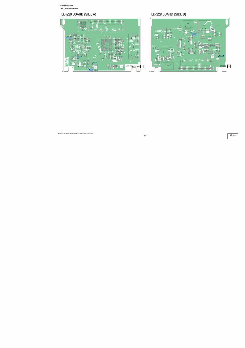
7/18/2019 SONY+HVR-HD1000 SERVICE MANUAL
http://slidepdf.com/reader/full/sonyhvr-hd1000-service-manual 84/425
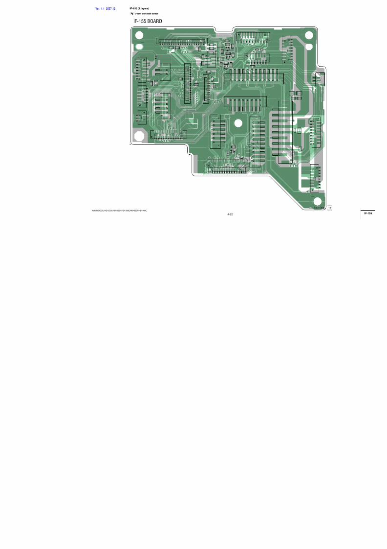
7/18/2019 SONY+HVR-HD1000 SERVICE MANUAL
http://slidepdf.com/reader/full/sonyhvr-hd1000-service-manual 85/425
4-37
HVR-HD1000J/HD1000U/HD1000N/HD1000E/HD1000P/HD1000C
(Page 4-39)
Flexible Flat Cable
(FFC-107)
Through the
MS-379CN8003
2 3
4 1
A
D
3
F
C
2
E
B
1
E
B
D
F
A
C
4
D8101
1SS357(T3SONY1)
LF8101
XX
1 3
42
D8102
MAZW068H0LS0
32
1
R8101
10k
CN8102 8P
1
2
3
4
5
6
7
8
R810210k
CN8101 8P
1
2
3
4
5
6
7
8
C N81 03 4 P
1
2
3
4
5 6 7
8R8103
0
R81040
LN8101
CHASSIS_GND
LN8102
CHASSIS_GND
N.C.
SWP
RF_MON
REG_GND
N.C.
N.C.
GND
N.C.
D-
SWP
REG_GND
VCC
USB_D-
D+
GND
RF_MON
USB_D+
REG_GND
USB_DET
REG_GND
(USB)
USB(B)
USB CONNECTOR
XX MARK:NO MOUNT
US-014 BOARD
CPC
(For Check)
05
Flexible Flat Cable
(FFC-338)
Through the
BH-001CN6002
(Page 4-35)
D
3
C
21
B
A
C5901
0.1uB
CN5901 20P
1
2
3
4
5
6
7
8
910
11
12
13
14
15
16
17
18
19
20
R5901XX
R5902XX
C59021uB
D5901NESW007AT-T099
RB5901XX
D5902
EDZ-TE61-5.6B
EVF_VDD
EP_4.6V
LED_K
EVF_GND
EVF_HST
EVF_COM
EVF_HCK2
EVF_REF
EVF_PSIG
EVF_VR
EVF_VG
EVF_VCK
EVF_VB
EVF_PCG
EVF_HCK1
EVF_STB
EVF_VST
EVF_EN
EVF_GND
EVF_GND
(EVF BACKLIGHT)
05
7 85 63 41 2
C
3
C
21
B
A
D851
XX
C851XX
S0851
1 2
43
(PANEL REVERSE)
PANXX MA
RE
05
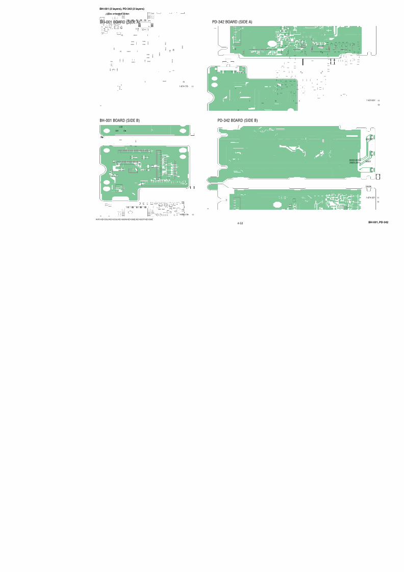
7/18/2019 SONY+HVR-HD1000 SERVICE MANUAL
http://slidepdf.com/reader/full/sonyhvr-hd1000-service-manual 86/425
4-38
HVR-HD1000J/HD1000U/HD1000N/HD1000E/HD1000P/HD1000C
(Page 4-34)
Through the
(IJ-002)
IF-155
Harness
CN0114
A
3
C
2
B
1
B
A
C
4
D703NSAD500H-T1-A
JACK_IN
D3_LNO_Y
D3_LNO_PB
D3_LNO_PR
D3_LNO_Y
D3_LNO_PR
JACK_IN
D3_LNO_PB
LND701
CHASSIS_GND
J0703
1
32
4
6
5
7
8
LND702
CHASSIS_GND
CN0701 8P
1
2
3
4
5
6
7
8
R703XX
R702XX
R701XX
R704XX
Y
PB
PR
GND
GND
GNDREG_GND
COMPONENT_JACK_IN
REG_GND
D3_LNO_Y
REG_GND
D3_LNO_PB
REG_GND
D3_LNO_PR
OUTCOMPONENT
COMPONENT CONNECTORXX MARK:NO MOUNT
JK-355 BOARD
Y
Pb/Cb
Pr/Cr
05
3 12
4 5
(Page 4-34)
Through the
(IJ-001)
IF-155
Harness
CN0113
XRESET
XRESET
S
S S
S
G
G
C
Y
A
D
3
C
2
B
1
B
D
A
C
4
S_C_OUT
S_Y_OUT
AUDIO_L_OUT
VIDEO_OUT
AUDIO_R_OUT
V D 7 5 3
V D 7 5 2
V D 7 5 1
FB752
FB751
J0701
R754
1kD751MAZS068G08S0
S_C_OUT
AUDIO_R_OUT
S_Y_OUT
AUDIO_L_OUT
VIDEO_OUT
LND753CHASSIS_GND
D752XX
3
21
D754XX
3
21
R 75 1 XX
R 75 2 XX
LND754
CHASSIS_GND
R757XX
R756XX
J0702
1
1
3 5 7
2
4 6 8
2
3
4
5
6
7
89
S0701
1
3
2
4
R 75 3 XX
CN0702 12P
1
2
3
4
5
6
7
8
9
10
11
12
R
L
V
REG_GND
S_Y_OUT
S_C_OUT
VIDEO_OUT
AUDIO_R_OUT
AUDIO_L_OUT
REG_GND
REG_GND
REG_GND
REG_GND
REG_GND
A/V CONNECTORXX MARK:NO MOUNT
S VIDEO
A/V OUT
VIDEO
RESET
JS-033 BOARD
AUDIO
L
R
05
XRESET
D
3
C
2
E
1
B
A
R655
R653
FB652
VDR652
FB651
D654RSE6.8XN-TR
1 2
6 5 4
3
R651 0
VDR653VDR651
R654
TH651
TH653
TH654
TH652RB651
0
CN0605 4P
1NTPB
2TPB
3NTPA
4TPA
5
6
J651
1
2
3
4
J652
SIG1
2 LANC_DC3 GND
4 232C_TD
5 JACK_IN
R652XX
LANC
(HEADPHONES)
HDV/DV
XX MA
LAN
HP
05
7 85 63 41 2
321
B
A
R401
0
LND401
CHASSIS_GND
J401
1
2
3
4
VDR402
VDR401
R403 XX
R404 XX
470PF
C401
(PLUG IN POWER)MIC
MX
M
05
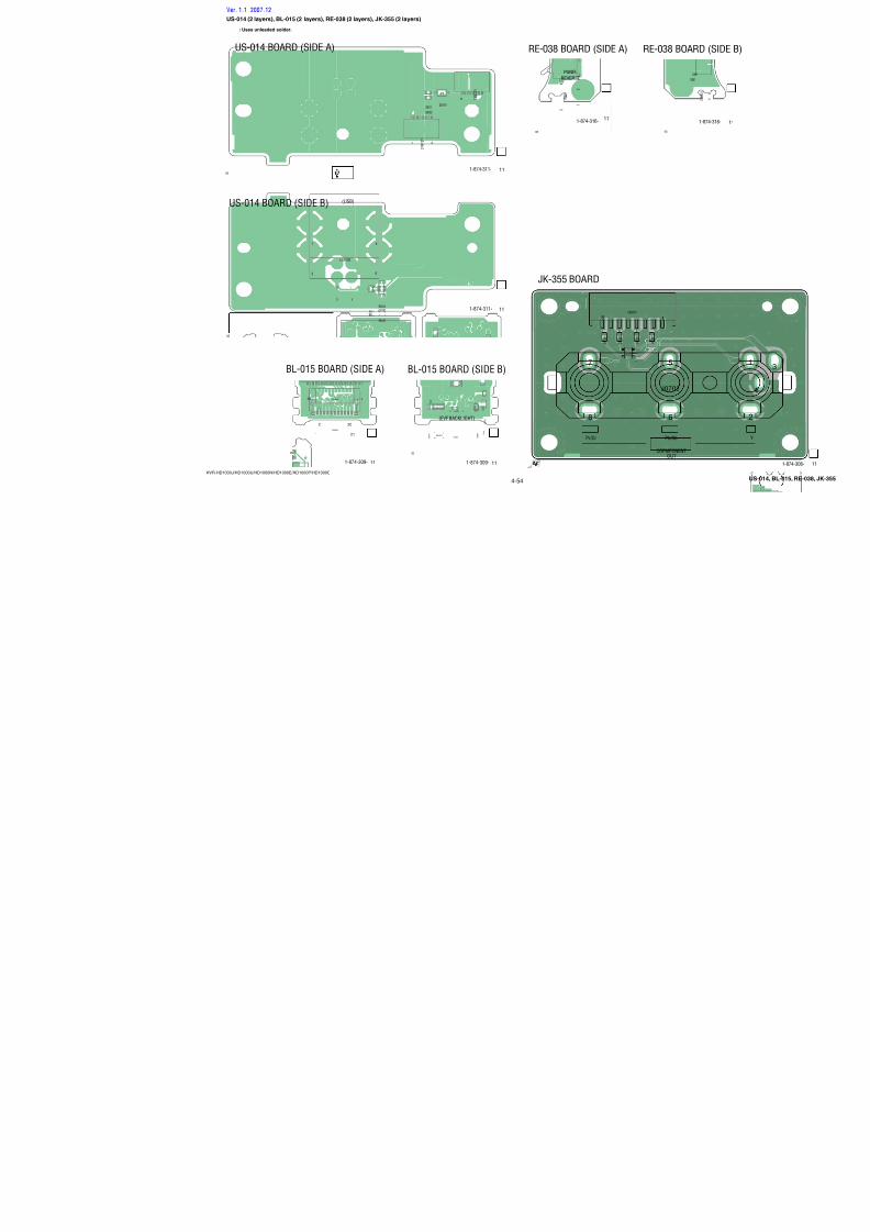
7/18/2019 SONY+HVR-HD1000 SERVICE MANUAL
http://slidepdf.com/reader/full/sonyhvr-hd1000-service-manual 87/425
4-39
HVR-HD1000J/HD1000U/HD1000N/HD1000E/HD1000P/HD1000C
• Refer to page 4-3 for mark 0.
FLEXIBLEFP-786
(Page 4-43)
(Page 4-37)
US-014CN8101
Flexible Flat Cable(FFC-107)
Through the
IF-155
(Page 4-34)
CN0106Through the
(MI-076)Harness
Note:BT901 (lithium battery) is not included in MS-379 complete board.
3 6 9
B
7
C
8
D
G
E
H
1 4
A
2 5
F
MS_INSERT
MS_SCLK
MSDATA3
MSDATA2
MS_DIO
MSDATA1
MS_BS
C8001
XX
C N8004 10P
1
2
3
4
5
6
7
8
9
10
LN8002
CH_GND
LN8001
CH_GND
R8001330
R8002 0
R8007 0
0R8008
R8003 0
R8004 0
R8005 0
R8006 0
C N8 00 1 2 6P
1
2
3
4
5
6
7
8
9
10
11
12
13
14
15
16
17
18
19
20
21
22
23
24
25
26
D8001XX
C N8003 8P
1
2
3
4
5
6
7
8
BH8001
D8003
CL-271HR-C-TS
CN8002 2P
1 SP(-)
2 SP(+)
D8004XX
32
1
MSDATA2(NC)
VCC
DIO
SCLK
MSDATA1(NC)
MSDATA3(NC)
BS
INS
GND
D_2.8V
GND
SWP
REG_GND
REG_GND
REG_GND
REG_GND
REG_GND
REG_GND
RF_MON
USB_D-
USB_D+
USB_DET
SP-
SP+
D_2.8V
XACCESS_LED
VBATT
MS_BS
MS_SCLK
MSDATA1
REG_GND
MSDATA2
MS_VCC
REG_GND
MS_DIO
MS_INSERT
MSDATA3
SWP
RF_MON
REG_GND
USB_D-
USB_D+
REG_GND
REG_GND
USB_DET
XACCESS_LED
(MS ACCESS)
DUOSTICK
MEMORY
LITHIUMBATTERY
BT901
(BATTERY HOLDER)
05
32
1
11
12
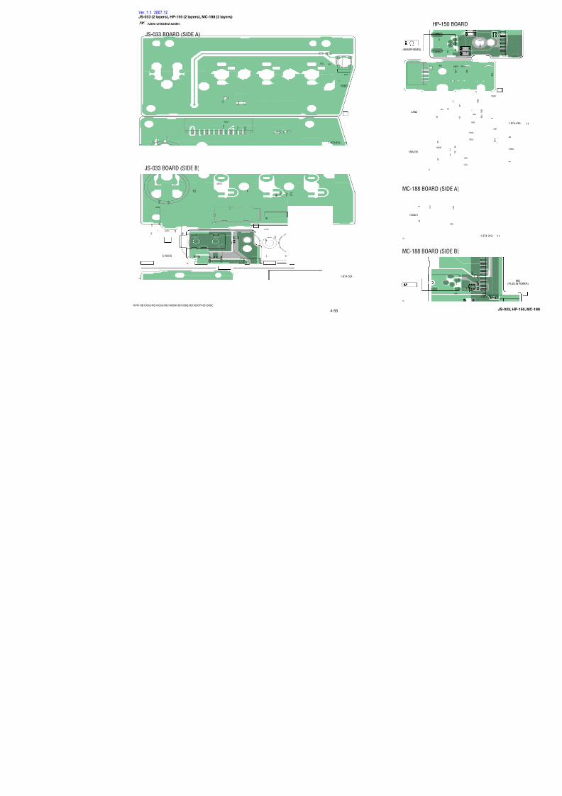
7/18/2019 SONY+HVR-HD1000 SERVICE MANUAL
http://slidepdf.com/reader/full/sonyhvr-hd1000-service-manual 88/425
4-40
HVR-HD1000J/HD1000U/HD1000N/HD1000E/HD1000P/HD1000C
(Page 4-34)
CN0117
Flexible Flat Cable
(FFC-337)
Through the
IF-155
(Page 4-40)
(FFC-336)
Through theFlexible Flat Cable
CN0504MO-027
A
D
3
F
C
2
E
B
1
E
B
D
F
A
C
4
S0503
MODE_LED_VDD
XCAM_LED
XMEM_LED
XVTR_LED
XCAM_LED
XMEM_LED
XVTR_LED
MODE_LED_VDD
D501EMZ6.8ET2R
5 4
321
SP+
SP-
SP-
SP+
C502XX
C503XX
C504XX
LND502
CHASSIS_GND
C501XX
S0504
S0501
1
3
2
4
3
1
4
2
4
1
3
2
S0502
1 42 3
7
86
5
R501 XX
R502 0
CN0501 14P
1
2
3
4
5
6
7
8
9
10
11
12
13
14
CN0502 8P
1
2
3
4
56
7
8
SP(+)
SP(-)
REG_GND
MODE_LED_VDD
XCAM_LED
XMEM_LED
XVTR_LED
PON_SW
REG_GND
REG_GND
XBATT_INFO_SW
N/S_SW
BACK_LIGHT_SW
REG_GND
REG_GND
REG_GND
XVTR_LED
XMEM_LED
XCAM_LED
MODE_LED_VDD
SP(+)
SP(-)
BATT INFODISPLAY/
OFFON
NIGHTSHOT
BACK LIGHT
MANUAL
XX MARK:NO MOUNT
CONTROL SWITCH
SP-048 BOARD
05
D
C
2
E
1
B
F
A
D 5 5 1
S M L - 5 1 2 W W T 8 6
D 5 5 2
S M L - 5 1 2 W W T 8 6
D553
XX
D554
XX
D555XX
D556XX
D557XX
D558
CL-196SYG-CD-T
D 5 5 9
R551
47R552
47
R5547
D551 D552 D558,D559
TAPE MEMORY PLAY/EDIT
05
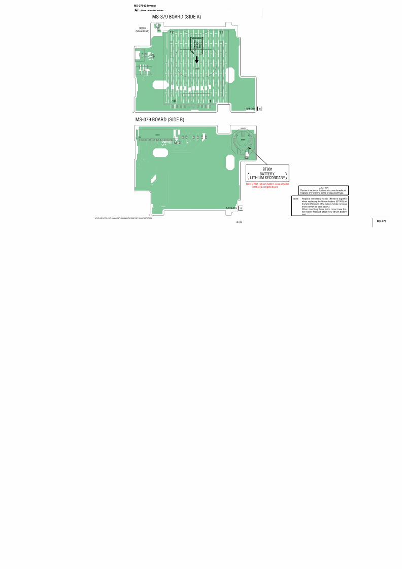
7/18/2019 SONY+HVR-HD1000 SERVICE MANUAL
http://slidepdf.com/reader/full/sonyhvr-hd1000-service-manual 89/425
4-41
HVR-HD1000J/HD1000U/HD1000N/HD1000E/HD1000P/HD1000C
(Page 4-45 )
LND307-LND312
FP-793FLEXIBLE
(FFC-329)
IF-155CN0101
Flexible Flat CableThrough the
(Page 4-34)
R1.9/P2.8
R2.8/P0
R0/P2.8
0
NO MARK:REC/PB MODE R:REC MODE P:PB MODE
A
D
3
F
C
2
E
B
1
E
B
D
F
A
C
4
R 2 0 4
4 7 0
D201
CL-196HR-CD-TD202
CL-196HR-CD-T
D203
CL-196HR-CD-T
R 2 0 5
4 7 0
R 2 0 6
4 7 0
LND201
CHASSIS_GND
CN0201 6P
1REG_GND
22ND_ZOOM(W)
32ND_ZOOM(T)
42ND_S/S_SW
5REG_GND
6REG_GND
R2016800
R2022700
R203XX
CN0207 8P
1
2
3
4
5
6
7
8
C2010.1u
B
R 2 0 8
2 2 k
Q201DTC114EMT2L
Q202DTC144EMT2L
A_4.6V
REG_GND
REG_GND
XF_TALLY_LED
REG_GND
KEY_AD2
XF_TALLY_LED
A_4.6V
D201-D203
(CAMERA RECORDING)
LED DRIVE
Q201,Q202
XX MARK:NO MOUNT
TALLY LED
HI-078 BOARD
05
(Pa
L
C
Flexib
(F
Th
NO MARK:REC/PB MODE
1.1
2.2 0
0
3
C
21
B
A
PH5501GP1S092HCPIF
PH5502GP1S092HCPIF
C55010.01u
B
LND301
CHASSIS_G
R5501330
CN5311 6
1
2
3
4
5
6
REG_GN
REG_GN
A_4.6V
A_4.6V
DIAL_A
DIAL_B
PH5501,PH5502
MANUAL FOCU
EC-001 B
05
1 3
2 4
1 3
2 4
MANUAL FOCUS/ZOOMSENSOR
LND202-LND207(Page 4-45)
SWITCHCONTROL
BLOCK(ZM90500)
LND102-LND107(Page 4-45)
SWITCHCONTROL
BLOCK(PS90500)
R901 22
R902 22
C90110u
B
D902XX
D903XX
D901CL-335IRS-X-TS
CN0903 6P
1
2
3
4
5
6
C N0 90 2 6 P
1
2
3
4
5
6
XPOWER_SW
REG_GND
D_2.8V
XS/S_SW
PHOTO REC
PHOTO FREEZE
REG_GND
REG_GND
ZOOM_AD
XMODE_SW
REG_GND
REG_GND
(NIGHTSHOT)
3 21
4 5
3 21
4 5
3
2
1
4
5
XX MARK:N
CONNE
NS-0
D
3
C
2
E
1
B
A
05
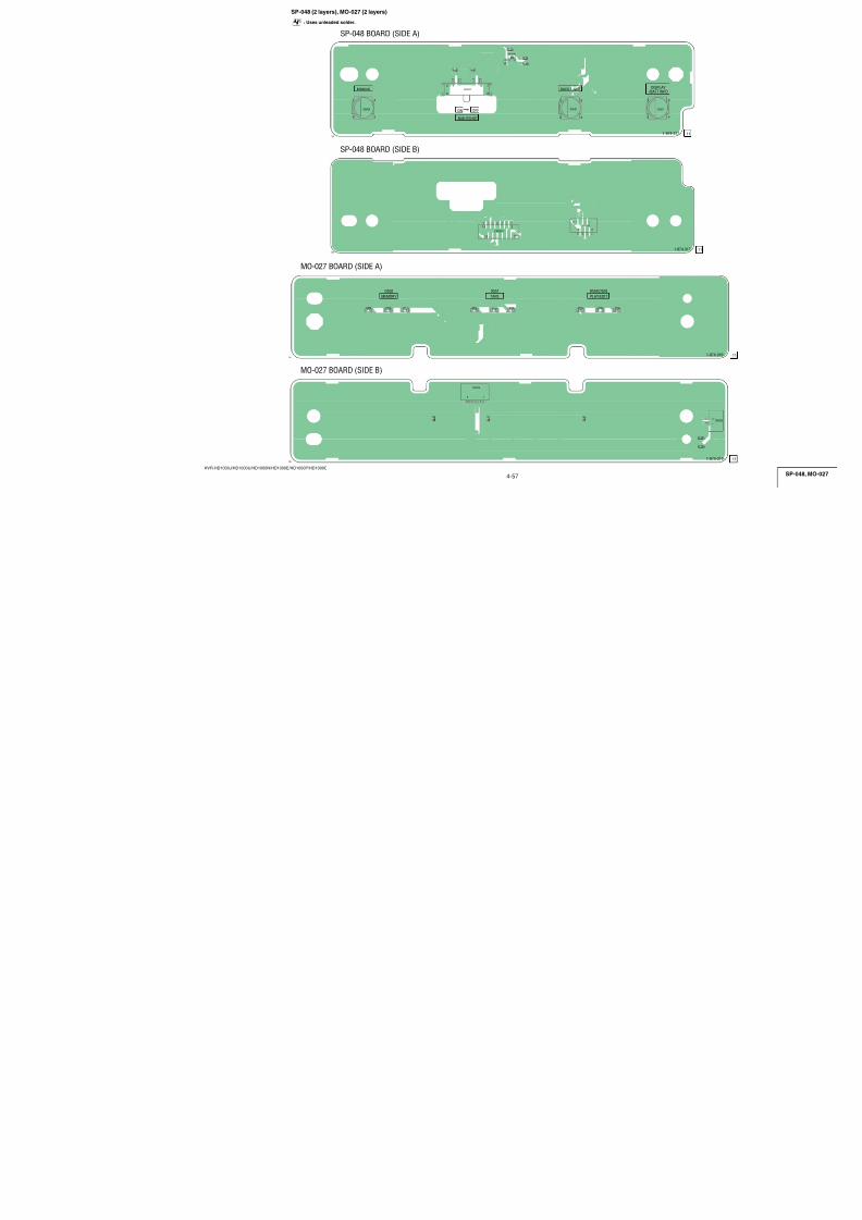
7/18/2019 SONY+HVR-HD1000 SERVICE MANUAL
http://slidepdf.com/reader/full/sonyhvr-hd1000-service-manual 90/425
4-42
HVR-HD1000J/HD1000U/HD1000N/HD1000E/HD1000P/HD1000C
• Refer to page 4-3 for mark 0.
Through the
(BD-058)
(Page 4-42)
DC-110
Harness
CN0601
Note:CN0651 is not supplied, but this is included in BA-008 complete board.
C
SW
A
32
B
1
B
A
4
CN0652 3P
1 BATT_GND
2 BATT_SIG
3 BATT_UNREG
CN0651
1
2
3
4
(BATT IN)
BATTERYTERMINAL
BATTERY IN
BA-008 BOARD
05
Through the
(BD-058)
(Page 4-42)
BA-008
Harness
CN0652
CN0116
(Page 4-34)
(DI-003)
IF-155
HarnessThrough the
A
D
3
C
2
B
1
B
D
A
C
4
D603XX
LND601
CHASSIS_GND
CN0602 9P
1
2
3
4
5
6
7
8
9
R6070
R6080
C603XX
C604XX
LF601
XX
CN0610
1 AVC_UNREG
3 ACV_GND
2
ACV_XEXT
R602
XX
R601
XX
D601CL-271TLY-C-TS
D602EDZ-TE61-5.6B
D606XX
D605XX
CN0601 3P
1
2
3
BATT_UNREG
BATT_GND
BATT_SIG
AVC_UNREG
ACV_GND
ACV/XEXT
ACV_GND
CHARGE_LED_VDD
XCHARGE_LED
BATT_UNREG
BATT_SIG
BATT_GND
DC IN
CHG
DC IN, CHARGE LEDXX MARK:NO MOUNT
DC-110 BOARD
05
4 3
1 2
VC-500
(Page 4-17)
CN3202(11/23)
D
C
21
B
A
TMDS DATA2 -
GND
GND
TMDS DATA1 +
GND
GND
TMDS DATA0 -
GND
GND
TMDS DATA0 +
GND
TMDS CLOCK -
TMDS CLOCK +
TMDS DATA1 -
TMDS DATA2 +
SCL
HPD
SDA
+5V POWER
1
20PIN
+5V POWER
20
HDMI CO
FP-86
05
(Pag
CNBH
2.8 2.8
NO MARK:REC/P
21
B
A
REG_G
REG_G
D_2.8V
D_2.8V
OPEN/C
REG_GC8010.1u
B
IC801
TK60011CS8
12
3
O U
T
V C
C
G N D
OPEN/CLOSE
DETECT
OPEN/CLO
FP-78
05
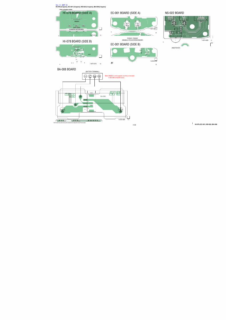
7/18/2019 SONY+HVR-HD1000 SERVICE MANUAL
http://slidepdf.com/reader/full/sonyhvr-hd1000-service-manual 91/425
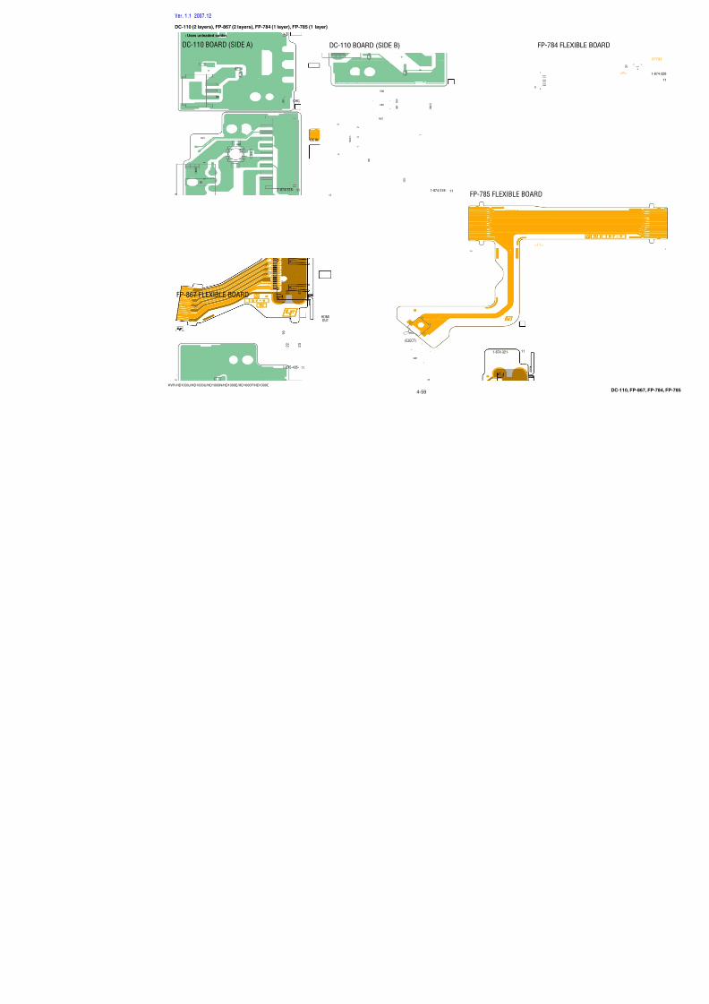
7/18/2019 SONY+HVR-HD1000 SERVICE MANUAL
http://slidepdf.com/reader/full/sonyhvr-hd1000-service-manual 92/425
4-44
HVR-HD1000J/HD1000U/HD1000N/HD1000E/HD1000P/HD1000C
(PRINTED WIRING BOARD is omitted.)
(Page 4-34)
CN0119IF-155VC-500
(Page 4-29)
CN1007(23/23)
A
D
3
F
C
2
E
B
1
E
B
D
F
A
C
4
1pin
AUDIO_R_I/O
HP_GND
HP_L_OUT
REG_GND
REG_GND
XHP_JACK_IN
S_Y_I/O
D3_CN
REG_GND
LINE_CNT1
REG_GND
REG_GND
TPA+
REG_GND
TPB+
AUDIO_L_I/O
REG_GND
MULTI_JACK_IN
HP_R_OUT
LINE_CNT3
D3_LNO_Y
LINE_CNT2
REG_GND
LANC_SIG
REG_GND
D3_LNO_PR
TPA-
HP_GND
D3_LNO_PB
REG_GND
REG_GND
XLANC_JACK_IN
TPB-
HP_GND
S_C_I/O
LANC_DC
REG_GND
VIDEO_I/O
REG_GND
1Pin
39Pin
REG_GND
HP_GND
REG_GND
S_Y_I/O
D3_LNO_PB
TPB-
HP_R_OUT
REG_GND
HP_GND
TPA+
LINE_CNT1
REG_GND
XLANC_JACK_IN
REG_GND
REG_GND
REG_GND
TPB+
REG_GND
REG_GND
REG_GND
LINE_CNT2
HP_GND
REG_GND
LANC_SIG
LINE_CNT3
AUDIO_R_I/O
XHP_JACK_IN
MULTI_JACK_IN
LANC_DC
D3_LNO_PR
REG_GND
D3_CN
HP_L_OUT
S_C_I/O
VIDEO_I/O
TPA-
REG_GND
D3_LNO_Y
AUDIO_L_I/O
39pin
VC-IF CONNECTION
FP-788 FLEXIBLE BOARD
05
(Page 4-29)
CN1017
VC-500(23/23)
(PRINTED WIRI
17PIN
22PIN
16PIN
12PIN
23PIN
20PIN
21PIN
24PIN
1PIN
5PIN
4PIN
11PIN
6PIN
15PIN
3PIN
2PIN
7PIN
13PIN
14PIN
18PIN
8PIN
19PIN
10PIN
9PIN
26PIN
25PIN
PLBL(PANEL_B)
KEY_AD5(RVS)
EP_4.6V
EP_8.5V
XVD_SCK(XBB_SCK)
REG_GND
REG_GND
EP_8.5V
EP_XVD(PANEL_VD)
A_4.6V(BL_-V)
PLGR(PANEL_G)
EP_2.8V
VD_SO(BB_SO)
A_4.6V(BL_-V)
XBATT_INFO_SW
REG_GND
KEY_AD6(O/C)
EP_XHD(PANEL_HD)
XCS_LCD
REG_GND
EP_2.8V
TP_SEL1
PLRE(PANEL_R)
KEY_AD2(SB)
VD_SI(BB_SI)
XRESET
D_2.8V
TP_Y
REG_GND
REG_GND
REG_GND
REG_GND
TP_X
28PIN
33PIN
31PIN
27PIN
32PIN
30PIN
29PIN
VC-IF CON
FP-78
D
C
2
E
1
B
F
A
05
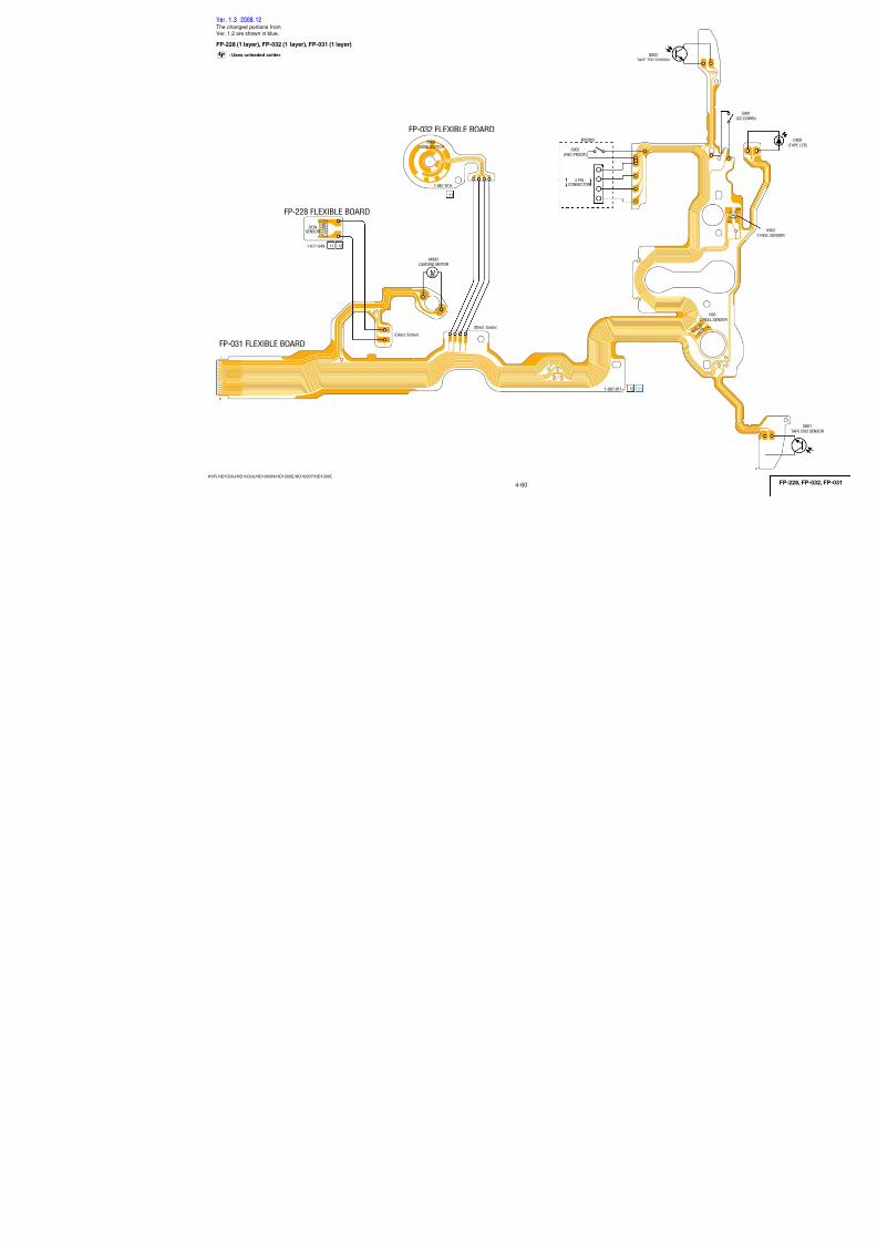
7/18/2019 SONY+HVR-HD1000 SERVICE MANUAL
http://slidepdf.com/reader/full/sonyhvr-hd1000-service-manual 93/425
4-45
HVR-HD1000J/HD1000U/HD1000N/HD1000E/HD1000P/HD1000C
(Page 4-41)
CN0201HI-078
(PRINTED WIRING BOARD is omitted.)
A
3
C
2
B
1
B
A
C
4
LND301
LND302
LND303
LND304
LND305
LND306
LND3092ND_ZOOM(T)
LND3102ND_S/S_SW
LND3082ND_ZOOM(W)
LND311REG_GND
LND312REG_GND
LND307REG_GND
REC, ZOOM SWITCH
FP-793 FLEXIBLE BOARD
T
W
(ZOOM)
RECSTART/STOP
05
(Page 4-41)
CN0903NS-022
CONTROL SWITCH BLOCK (ZM90500) is replaced as block,so that PRINTED WIRING BOARD is omitted.
A
3
C
2
B
1
B
A
C
4
RV201
S202
LND203
LND206
S201
LND205
LND204
LND202
LND207
PHOTO FREEZE
REG_GND
ZOOM_AD
D_2.8V
PHOTO REC
REG_GND
(ZOOM)
(PHOTO FREEZE)
PHOTO
(PHOTO REC)
(ZM90500)CONTROL SWITCH BLOCK
W T
05
C
21
B
A
S102
S101
XMODE_SW
XPOWER_SW
POWER
(START/STOP)
05
PLAY/EDIT
OFF (CHG)
TAPE
MEMORY
CONTROL SWITCHso that PRINTED W
(PS9050CONTRO
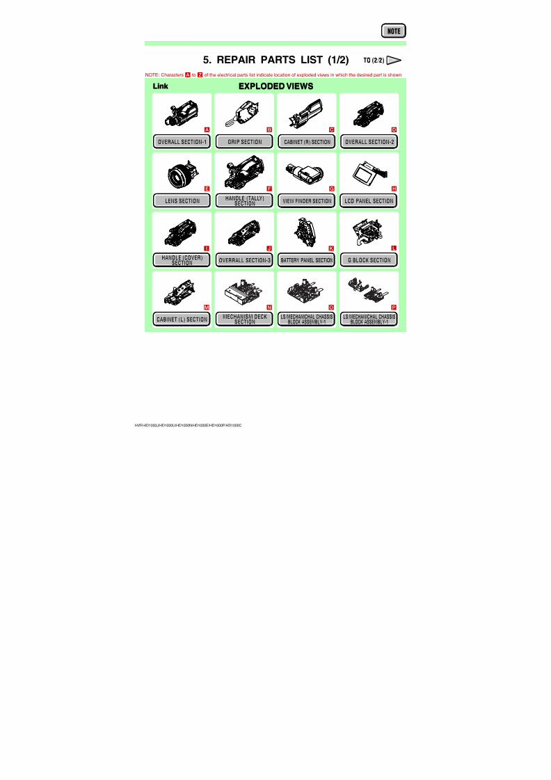
7/18/2019 SONY+HVR-HD1000 SERVICE MANUAL
http://slidepdf.com/reader/full/sonyhvr-hd1000-service-manual 94/425
4-46
HVR-HD1000J/HD1000U/HD1000N/HD1000E/HD1000P/HD1000C
(16/23)
(Page 4-22)
CN4801
VC-500
MIC903
4 PIN
CONNECTOR
Q902PT4850FJE00F
TAPE TOPSENSOR
S903(MODE SWITCH)
FP-032FLEXIBLEBOARD
FP-228FLEXIBLE
BOARD
DEWSENSOR
S902(REC PROOF)
FP-031 FLEXIBLE BOARD
MECHANISM BLOCK
M902LOADING MOTOR
05
L M
_ L O A D
L M
_ L O A D
L M
_ U N L O A D
L M
_ U N L O A D
D E W -
D E W +
X M O D E
_ S W
_ A
X M O D E
_ S W
_ B
X M O D E
_ S W
_ C
S W
_ C O M / S W
_ G N D
X R E C
_ P R O O F
C H I M E
_ V D D
C H I M E
_ S D A
C H I M E
_ S C K
M I C / R E C
_ S W
_ G N D
T A P E
_ T O P
X C C D O W N
_ S W
C i n
_ G N D
T R E E L -
T R E E L
1 2 3 4 5 6 7 8 9 1 0
1 1
1 2
1 3
1 4
1 5
1 6
1 7
1 8
1 9
2 0
1
A
D
F
B
E
53
C
62 74
S 9 0 1
( C C D O W N )
DEW-
DEW+
1
2
XMODE_SW_A
XMODE_SW_B
1
2
XMODE_SW_C
SW_COM/SW_GND
3
4
DEW-
DEW+
1
2
XMODE_SW_A
XMODE_SW_B
1
2
XMODE_SW_C
SW_COM/SW_GND
3
4
M

7/18/2019 SONY+HVR-HD1000 SERVICE MANUAL
http://slidepdf.com/reader/full/sonyhvr-hd1000-service-manual 95/425
4-3. PRINTED WIRING BOARDS
HVR-HD1000J/HD1000U/HD1000N/HD1000E/HD1000P/HD1000C
Link Link
VC-500 BOARD (SIDE A)
CM-077 BOARD MC-188 BOARD
MS-379 BOARD
LD-229 BOARD
VC-500 BOARD (SIDE B) SP-048 BOARD
MO-027 BOARD
BH-001 BOARD
IF-155 BOARD HI-078 BOARD
EC-001 BOARD
US-014 BOARD
PD-342 BOARD NS-022 BOARD
BA-008 BOARD
RE-038 BOARD
BL-015 BOARD DC-110 BOARD
FP-867 FLEXIBLE BOARD
JS-033 BOARD
JK-355 BOARD FP-784 FLEXIBLE BOARD
FP-785 FLEXIBLE BOARD
HP-150 BOARD FP-228, FP-032, FP-031 FLEXIBLE BOARD
COMMON NOTE FOR PRINTED WIRING BOARDS
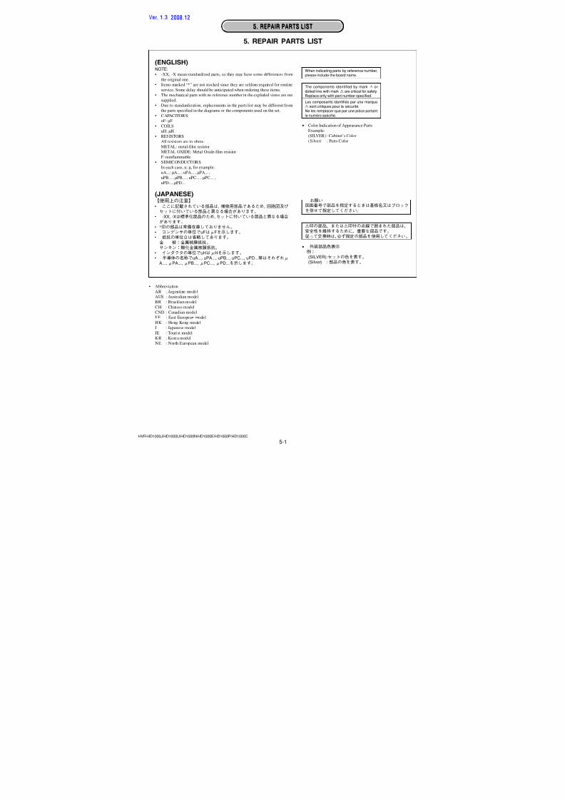
7/18/2019 SONY+HVR-HD1000 SERVICE MANUAL
http://slidepdf.com/reader/full/sonyhvr-hd1000-service-manual 96/4254-47HVR-HD1000J/HD1000U/HD1000N/HD1000E/HD1000P/HD1000C
4-3. PRINTED WIRING BOARDS4-3. PRINTED WIRING BOARDS
• : Uses unleaded solder.
• : Circuit board: Flexible board
Pattern from the side which enables seeing.
: pattern of the rear side(The other layers’ patterns are not indicated)
• Through hole is omitted.• There are a few cases that the part printed on diagram
isn’t mounted in this model.•C: panel designation
(ENGLISH)THIS NOTE IS COMMON FOR PRINTED WIRING BOARDS
4-3. PRINTED WIRING BOARDS
(JAPANESE)
2 1
3
2 1
3
2 1
3
345
21
123
654
EB
C
31
5
2
46
123
654
31
5
2
46
123
54
4 3
1 2
31 2
45
53 4
12
14
23
46
2
5
31
12
43
14
23
• Chip parts.
Transistor Diode
C
Ver. 1.3 2008.12
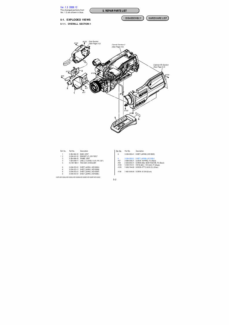
7/18/2019 SONY+HVR-HD1000 SERVICE MANUAL
http://slidepdf.com/reader/full/sonyhvr-hd1000-service-manual 97/425
4-48
HVR-HD1000J/HD1000U/HD1000N/HD1000E/HD1000P/HD1000C
CM-077 (6 layers)
: Uses unleaded solder.
RB7201
I C 6 7 0 1
F B 7 2 0 1
FB7202 FB7203
F B 7 2 0 4
L 7 2 0 1
S
E 7 2 0 1
SE7202
C7201
C7202
C7203 C7204
C 7
2 0 5
C 7
2 0 6
C 7
2 0 7
C 7
2 0 8
C
7 2 0 9
C7210C7211
R7201 R7202 R7203
R 7 2 0 4
I C 7 2 0 1
4 8
2 5
3 0
3 5
4 0
4 5
1
5
1 0
1 5
2 0
2 4
4
3
1
2
43
12
1 0 9 8 7 6
1 6 1 7 1 8 1 9 2 0
1 1 1 2 1 3 1 4 1 5
5
4
3
2
1
1 7
2 8(PITCH)
( Y A W )
CM-077 BOARD (SIDE A)
111-871-002-
05
A_ 2 . 8 V
Note: IC6701 is supplied including in CMOS block assy.
C6708
C 6 7 0 9
C 6 7 1 0
C 6 7 1 3
C6714
C 6 7 1 5
C6716
C6717
C 6 7 1 8
C 6 7 2 1
C 6 7 2 2
C6723
C6726
C6727
R 6 7 0 3
R 6 7 0 4
R 6 7 0 5
R 6 7 0 6
R 6 7 0 7
R 6 7 0 8
R6709
C6734
C 6 7 3 5
C6736
C 6 7 3 7
C6738
C6739
C 6 7 4 0 C
6 7 4 1
C 6 7 4 2
C6743
C6601
C6602
C 6 6 0 3
C 6 6 0 4
C 6 6 0 5
C6606
C 6 6 0 7
C6608
C6609
C6610
C6612
C 6 6 1 3
C6614
R6604
IC6604
IC6605
IC6606
L6701
L6702
L 6 7 0 3
L6704
L 6 7 0 8
L 6 7 0 9
CL6701
C 6 7 0 1
C 6 7 0 2
C 6 7 0 4
C6705
C 6 7 0 6
C6707
CN6601
R 6 6 1 6
R 6 6 1 5
R 6 6 1 4
R 6 6 1 3
R 6 6 1 2
R 6 6 1 1
IC6601 IC6602
+P
+ P +
P
+
P +
P
+
P
12
3 4
1 5 10 15 20 25
41
+P 12
3 4
+P
1 4
58
1 4
58
1 2
34 +
P
+
P
+P
+P
+
P
+
P
+P
CM-077 BOARD (SIDE B)
05
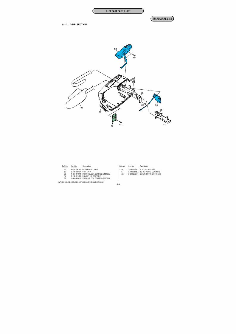
7/18/2019 SONY+HVR-HD1000 SERVICE MANUAL
http://slidepdf.com/reader/full/sonyhvr-hd1000-service-manual 98/425
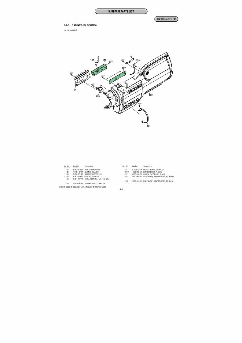
7/18/2019 SONY+HVR-HD1000 SERVICE MANUAL
http://slidepdf.com/reader/full/sonyhvr-hd1000-service-manual 99/425
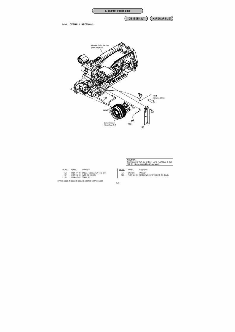
7/18/2019 SONY+HVR-HD1000 SERVICE MANUAL
http://slidepdf.com/reader/full/sonyhvr-hd1000-service-manual 100/425
4-51
HVR-HD1000J/HD1000U/HD1000N/HD1000E/HD1000P/HD1000C
LD-229 (6 layers)
: Uses unleaded solder.
>EP GW<
A
2
3 2
1
3 3
P
A
A
P
P
P
250
151
R5741
R5742R5745
R5746
R5749
R 5 7 7 0
R 5 7 7 1 R
5 7 7 2
R 5 7 7 3
R 5 7 7 4 R
5 7 7 6
R5787
R5788
R5790
R 5 7 9 1
R 5 7 9 2
R5793
R5795
R5796
C 5 4 0 9
C5410
C 5 4 1 1
C 5 4 1 2
C 5 4 1 3
C 5 4 1 4
C 5 4 1 5
C 5 4 1 6
C 5 4 1 7
C 5 4 1 8
C 5 4 1 9
C 5 8 0 1
C 5 8 0 4
C 5 4 2 0
C 5 4 2 2
C 5 4 2 3
C5424
C5425
C 5 4 2 7
C 5 4 2 8
C5430
C5431
C5433
C5434
IC5404
C 5 4 3 5
C 5 4 3 6
R 5 8 0 1
L 5 3 0 1
IC5801
R 5 4 3 3
R 5 4 3 4
R 5 4 3 5
R 5 4 3 6
R 5 4 3 7
R 5 4 3 8 R
5 4 3 9
R 5 4 4 0
R 5 4 4 1
R 5 4 4 2
R 5 4 4 3
R 5 4 4 4
R 5 4 4 5
R 5 4 4 6
R 5 4 4 7
R 5 4 4 8
R 5 4 4 9
R5450
R5451
R5452
R 5 4 5 3
R 5 4 5 4
R5455
R5456
R5457
R 5 4 5 8
R5459
R5460
R5461R5462
C L 5 7 0 1
C L 5 7 0 3
C L 5 7 0 4
C N 5 3 0 2
Q 5 3 0 2
C5313
C5314
C5315
C5316
C5318
C 5 7 0 6
C5707
C5708
C 5 7 0 9
F B 5 4 0 1
C5712
C5713
C5714
C5715
C5716
C5717
C5718
C5719
I C 5 3 0 4
C5722
C5723
C 5 7 2 4
C 5 7 2 5
C 5 7 2 6
C 5 7 2 7
C5728
IC5703
R5720
R 5 3 3 9
R 5 7 2 1
R 5 7 2 3
R5725
R5726
R5729
R5343
R5730
R5733
R5736
R 5 7 3 7
R 5 7 3 9
CN5301
1
3 4
6
A1B1C1D1E1F1G1H1J1K1L1M1
A2B2C2D2
A3B3C3D3
A4B4C4D4
A5B5C5D5
A6B6C6D6
A7B7C7D7
A8B8C8D8
A9B9C9D9
A10B10C10D10
A11B11C11D11
A12B12C12D12
J2K2L2M2
J3K3L3M3
J4K4L4M4
J5K5L5M5
J6K6L6M6
J7K7L7 M 7
J8K8L8M8
J9K9L9M9
J10K10L10M10
J11K11L11M11
J12K12L12M12 E12F12G12H12
E11F11G11H11
E10F10G10H10
E9F9G9H9
E2F2G2H2
E3F3G3H3
E4F4G4H4
F 6
E 6 D 6 C 6 B 6 A 6
F 5
E 5 D 5 C 5 B 5 A 5
F 4
E 4 D 4 C 4 B 4 A 4
F 3
E 3 D 3 C 3 B 3 A 3
F 2
E 2 D 2 C 2 B 2 A 2
F 1
E 1 D 1 C 1 B 1 A 1
K 5
K 6
K 7
K 8
K 9
K 2
K 3
K 4
K 1 0
K 1
E 1 0 F 1 0 G 1 0 H 1 0 J 1 0
E 9
F 9
G 9
H 9
J 5
J 6
J 7
J 8
J 9
B 5
B 6
B 7
B 8
B 1 0 C 1 0 D 1 0
A 5
A 6
A 7
A 8
A 9
C 9
D 9
B 9
E 1
F 1
G 1
H 1
J 1
E 2
F 2
G 2
H 2
J 3
J 4
J 2
B 1
A 2
C 1
D 1
A 3
A 4
C 2
D 2
B 3
B 4
B 2
A 1 0
A 1
E 4
F 4
G 4
D 4
E 5
G 5
D 5
G 6
D 6
E 7
F 7
G 7
D 7
4
3 2
1
LD-229 BOARD (SIDE A)
05
111-874-305-
MR_A2.8V
D_1.5V
D_2.8V
D_2.8V
1
5
8
4
A
1
5 8
4
5
4
1 6
16
P
P
1
5
8
4
2
1
C 5 4 0 1
C 5 4 0 2
C 5 4 0 4
C5405
C54R5401
R 5 4 0 2 R
5 4 0 3
R 5 4 0 4
R5405 R5406 R 5 4 0 9
IC5401
C5432
IC5402
IC5403
R5410
R5411
R5412
R5413
R5414
R 5 4 1 5
R5420
R5421
R 5 4 2 3
R5425
R54R5427
R 5 4 3 1
R547
R547
CN5304
CN5306
C 5 3 0 3
C 5 3 0 4
C 5 3 0 5
C 5 3 0 6
C 5 3 0 7
C 5 3 0 8
C5309
C5310
C5311 C 5 3 1 2
C 5 3 1 9
C 5 3 2 0
D5302
D 5 3 0 3
I C 5 3 0 3
R5325R5326
R5327
R5328
R5329 R 5 3 3 0
R5331
R 5 3 3 2
R5333
R 5 3 3 4
R5335
R5336
R5337 R5338
1
32
1 3
2
LD-229 BOARD (SIDE B)
05
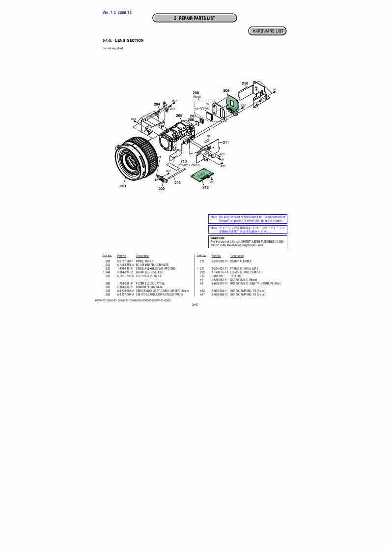
7/18/2019 SONY+HVR-HD1000 SERVICE MANUAL
http://slidepdf.com/reader/full/sonyhvr-hd1000-service-manual 101/425
4-52
HVR-HD1000J/HD1000U/HD1000N/HD1000E/HD1000P/HD1000C
IF-155 (4 layers)
: Uses unleaded solder.
1 2
7 8
1
2
19
201 20
1 5
1 1
1 0
1
2
1
4
1 2
1 1 1
2
1 2
1 3
1 4
1 2
6 5
1
6
112
1 8
1
1 0
1
9
1
2
13
14
1
322
33
2
1
38
39
1 2
1 5 1
6
Q101
Q102
Q103
Q 1 0 4
LND002
R 1 0 1
R102
R103
R 1 0 4
R105
R 1 0 6
R 1 0 7
R108
R 1 0 9
R 11 4 R 11 5
R118
R119
R120
R121
C101
C102
C103
C 1 0 4
CL0101
C105
CL0102
C106
CL0103
C 1 0 7
CL0104
C 1 0 8
CL0105
C109
CL0107
C110
R 1 2 2
C111
C 1 1 2
C113
C 1 1 4
C 1 1 5
C 1 1 6
C117
C 1 1 8
C 1 1 9
C 1 2 0
C121
C122
C N 0 1 0 1
CN0102
CN0103
C N 0 1 0 4
C N 0 1 0 5
C N 0 1 0 7
C N 0 1 0 8
C N 0 1 0 9
C N 0 1 1 0
C N 0 1 1 1
C N 0 1 1 2
CN0113
CN0114
C N 0 1 1 5
C N 0 1 1 6
CN0117
CN0118
CN0119
C N 0 1 2 2
C
BE
C
BE
C
BE
C
B
E
IF-155 BOARD
05
Ver. 1.1 2007.12
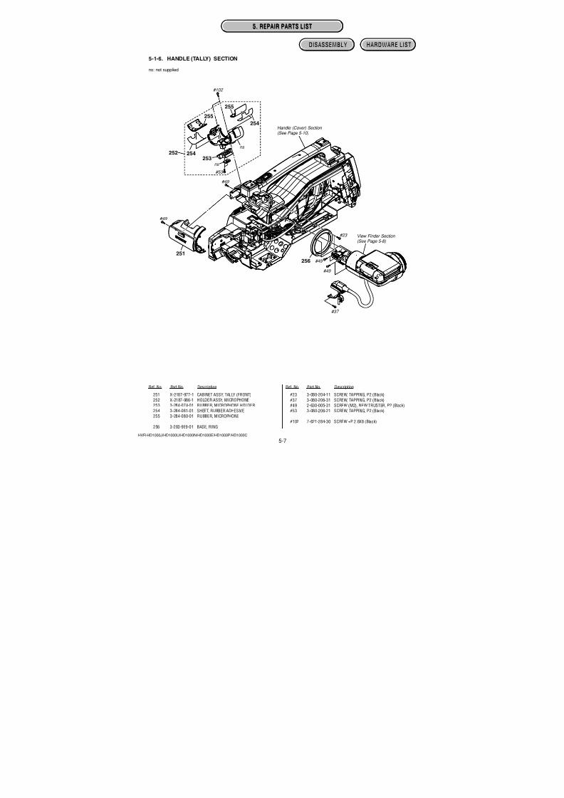
7/18/2019 SONY+HVR-HD1000 SERVICE MANUAL
http://slidepdf.com/reader/full/sonyhvr-hd1000-service-manual 102/425
4-53
HVR-HD1000J/HD1000U/HD1000N/HD1000E/HD1000P/HD1000C
BH-001 (2 layers), PD-342 (2 layers)
: Uses unleaded solder.
1 22
1 2
1 9 2
0
1
2 0
15 1
110
1 2
6 5
1 2
CN6001
C N 6 0 0 2
C N 6 0 0 3
CN6004
CN6005
C N 6 0 0 6
CN6007
C 6 0 0 2
C6003
C6004
C6005
Q6001
C6006
Q 6 0 0 2
C 6 0 0 7C6008
C 6 0 0 9
C 6 0 1 0
C 6 0 1 1
R 6 0 0 1
R 6 0 0 2
R6003
R 6 0 0 4
R 6 0 0 5
R6006
L N D 6 5 1
F B 6 0 0 1
FB6002
F B
6 0 0 3
C
C
B
B
E
E
BH-001 BOARD (SIDE A)
05
111-874-776-
C 6 0 0 1
D6001R6007R6008
S6001
1
5
6
7
8
4
LCD
ONOFF
BH-001 BOARD (SIDE B)
05111-874-776-
1
2 2
1 61 24
+
P
+P
+
1 7
2
1 8
1 9
LD6201
L6201
L6202
L6203
CN6201CN6205
C 6 2 0 1
C6202
C 6 2 0 3
C 6 2 0 4
Q 6 2 0 1
C6205
Q6202
C 6 2 0 6
C6207
Q 6 2 0 7
Q6208
C 6 2 1 0
C 6 2 1 2
C 6 2 1 3
Q 6 2 1 0
C 6 2 1 4
C 6 2 1 5
Q6211
Q6212
C6218
C 6 2 1 9
C6223
C6224
C6225
D6201
C6226
D6202
D 6 2 0 3
C6227
C 6 2 2 8
R6203
R6207R6208
IC6201
R6209R6210
R6215
R6219
R6220
R 6 2 2 8
R 6 2 2 9
R 6 2 3 0
R6233
R6235
R 6 2 3 6
R 6 2 3 7
R 6 2 4 1
F B 6 2 0 1
CN6202
1 3
46
1
3 4
6
1
3
6
4
1 3
46
1 3
45
D
S
G
D
G
S
C
B E
PD-342 BOARD (SIDE A)
05
PD-342 BOARD (SIDE B)
05
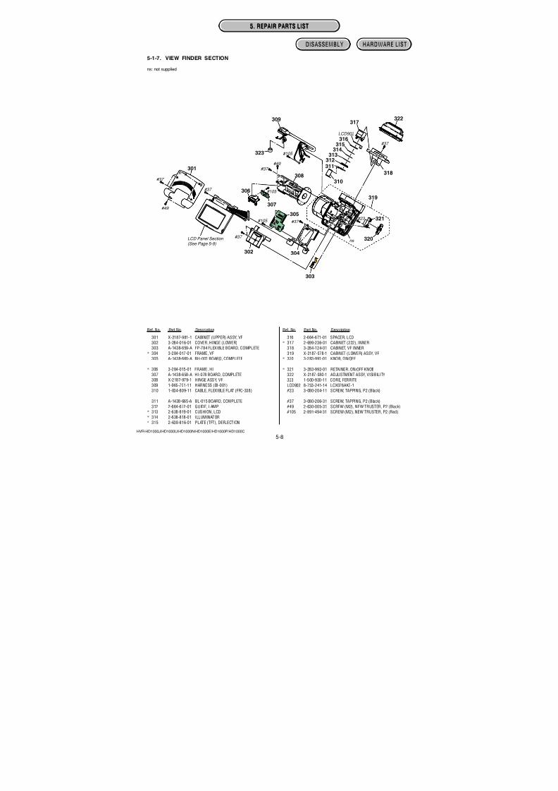
7/18/2019 SONY+HVR-HD1000 SERVICE MANUAL
http://slidepdf.com/reader/full/sonyhvr-hd1000-service-manual 103/425
4-54
HVR-HD1000J/HD1000U/HD1000N/HD1000E/HD1000P/HD1000C
US-014 (2 layers), BL-015 (2 layers), RE-038 (2 layers), JK-355 (2 layers)
: Uses unleaded solder.
18
1 8
C N 8 1 0 2
C N 8 1 0 1
D8101
R8102
R8101
US-014 BOARD (SIDE A)
05111-874-311-
R8104LF8101
R8103
D 8 1 0 2
12
3 4
5 6
7 8
CN8103
US-014 BOARD (SIDE B)
05
111-874-311-13
4 2 1
2
3
(USB)
120
1
2
21
20
CN5901
CN5902
BL-015 BOARD (SIDE A)
05
111-874-309-
RB5901C5901
C 5 9 0 2
C 5 9 0 3
D5901
D 5 9 0 2
R 5 9 0 1
R 5 9 0 2
R 5 9 0 4
1
2 6
7
(EVF BACKLIGHT)
A K
BL-015 BOARD (SIDE B)
05
111-874-309-
S 0 8 5 1
PANEL
REVERSE
1
2
4
3
RE-038 BOARD (SIDE A)
05
11
1-874-316-
RE-038 BO
05
Pr/Cr Pb/Cb
COPMPONENOUT
5
6
7
8
J0703
8 1
CN0701
D703
R 7 0 4
R 7 0 1
R 7 0 2
R 7 0 3
1
3 4
5
JK-355 BOARD
05
Ver. 1.1 2007.12
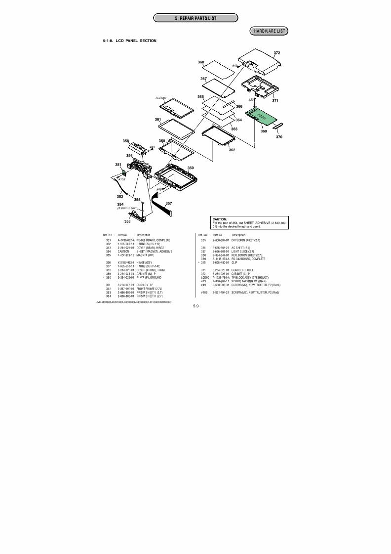
7/18/2019 SONY+HVR-HD1000 SERVICE MANUAL
http://slidepdf.com/reader/full/sonyhvr-hd1000-service-manual 104/425
4-55
HVR-HD1000J/HD1000U/HD1000N/HD1000E/HD1000P/HD1000C
JS-033 (2 layers), HP-150 (2 layers), MC-188 (2 layers)
: Uses unleaded solder.
R 7 5 6
R 7 5 7
R 7 5 3
VD753
S0701
D751R754
1
2
3
4
RESET
JS-033 BOARD (SIDE A)
05111-874-531-
12 1
1 6 7
24 35 98
D 7 5 4
F B 7 5 2
D 7 5 2
F B 7 5 1
CN0702
VD752
R 7 5 2
R 7 5 1
218
5 3 4 6
7
J0702J0701
A/V OUT
AUDIOVIDEOS VIDEO RL
1
2
3
1
2
3
VD751
JS-033 BOARD (SIDE B)
05111-874-531-
R65
CN060
J
LANC
HDV/DV
3
3
6
5
i(HEADPHONES)
HP-
05
1
4
CN0401
C 4 0 1
MC-188 BOARD (
05
MC-188 BOARD (
05
Ver. 1.1 2007.12
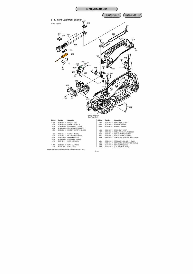
7/18/2019 SONY+HVR-HD1000 SERVICE MANUAL
http://slidepdf.com/reader/full/sonyhvr-hd1000-service-manual 105/425
4-56
HVR-HD1000J/HD1000U/HD1000N/HD1000E/HD1000P/HD1000C
MS-379 (2 layers)
: Uses unleaded solder.
Note: Replace the bwhen replacinthe MS-379 boonce cannot bWhen mountitery holder firsnext.
Danger of explosReplace only wi
2
1
1
2
7
8
110
12 11
C
N 8 0 0 2
CN8003CN8004
D8003
R 8 0 0 1
D 8 0
0 4
1
2
3
AK
(MS ACCESS)D8003
M E M O R Y
S T I C K
D U O
MS-379 BOARD (SIDE A)
05
111-874-310-
126
CN8001
C 8 0 0 1
R 8 0 0 2
R 8 0 0 3
R 8 0 0 4
R 8 0 0 5
R 8 0 0 6
R 8 0 0 7
R8008
BT901
BH8001
D8001
1
23
BT901BATTERY,LITHIUM SECONDARY
Note: BT901 (lithium battery) is not includedin MS-379 complete board.
MS-379 BOARD (SIDE B)
05
111-874-310-
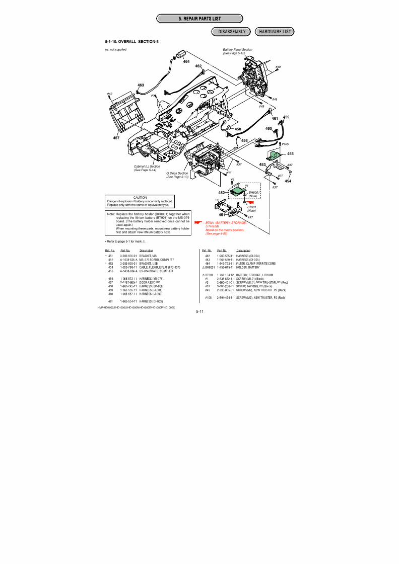
7/18/2019 SONY+HVR-HD1000 SERVICE MANUAL
http://slidepdf.com/reader/full/sonyhvr-hd1000-service-manual 106/425
4-57
HVR-HD1000J/HD1000U/HD1000N/HD1000E/HD1000P/HD1000C
SP-048 (2 layers), MO-027 (2 layers)
: Uses unleaded solder.
S0504
R502 R501
S0502
D501C502
C504 C 5 0 3
C501
S0503 S0501
4 5
13
NIGHTSHOT
ON OFF
MANUAL BACK LIGHT DISPLAY /BATT INFO
8
7
6
5 1 4
1
2
4
3
1
2
3
4
1
2
3
4
SP-048 BOARD (SIDE A)
051-874-3
1
2
13
14
1
2
7
8CN0501
CN0502
SP-048 BOARD (SIDE B)
051
AKAK AK AKAK AK
D556 D552 D557 D554 D551 D555 D558 D553 D559AK AK AK
PLAY/EDITMEMORY TAPE
D558,D559D552 D551
MO-027 BOARD (SIDE A)
05
18
R 5 5 2
R 5 5 1
CN0504
R 5 5 3
MO-027 BOARD (SIDE B)
05
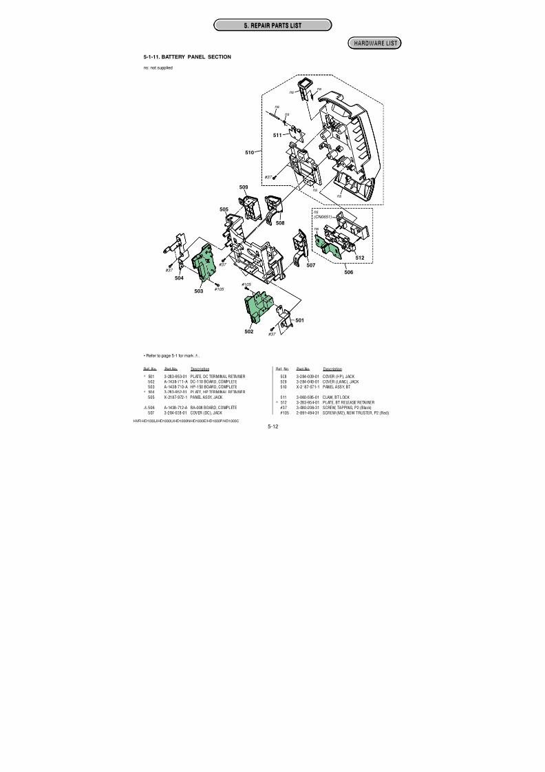
7/18/2019 SONY+HVR-HD1000 SERVICE MANUAL
http://slidepdf.com/reader/full/sonyhvr-hd1000-service-manual 107/425
4-58
HVR-HD1000J/HD1000U/HD1000N/HD1000E/HD1000P/HD1000C
HI-078 (2 layers), EC-001 (2 layers), NS-022 (2 layers), BA-008 (2 layers)
: Uses unleaded solder.
18
CN0207
D201D202D203A K A K A K
D201-D203
(CAMERA RECORDING)
HI-078 BOARD (SIDE A)
05 111-874-315-
16
C201
CN0201
LND201
Q201 Q202
R 2 0 1
R 2 0 2
R 2 0 3
R 2 0 4
R 2 0 5
R 2 0 6
R208
HI-078 BOARD (SIDE B)
05 111-874-315-
C
BE
C
BE
PH5501PH5502
12
34
12
34
EC-001 BOARD (SIDE A)
0511
1-874-314-
PH5501, PH5502
(MANUAL FOCUS/ZOOM SENSOR)
1
2 6
5
CN5311
C 5 5 0 1
R5501
EC-001 BOARD (SIDE B)
05 11
1-874-314-
1
26
5
C901
D902
CN0903
D901
1
3 4
5
1
32
(NIGHTS
NS-022 BO
05
>EP GW<
BA-008
1
3
CN0652
CN0651
(BATTERY TERMINAL)
C SW
4
3
2
1
Note: CN0651 is not supplied, but this is included in BA-008 complete board.
BA-008 BOARD
05111-875-404-
Ver. 1.1 2007.12
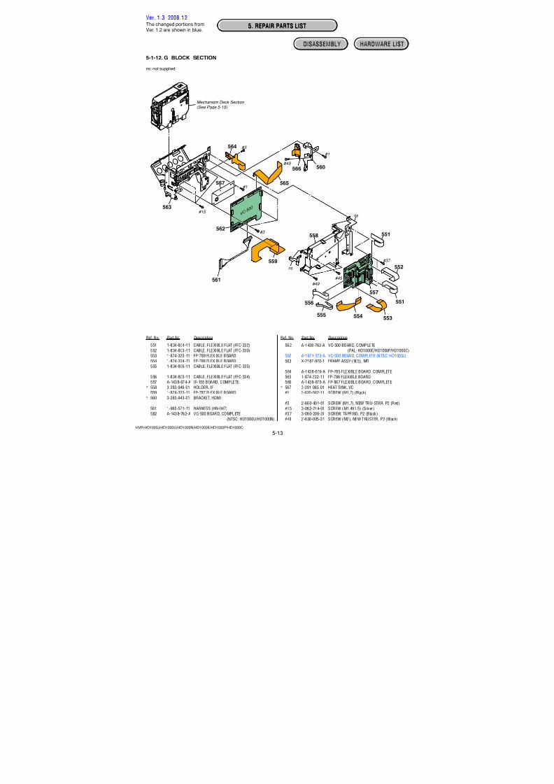
7/18/2019 SONY+HVR-HD1000 SERVICE MANUAL
http://slidepdf.com/reader/full/sonyhvr-hd1000-service-manual 108/425
4-59
HVR-HD1000J/HD1000U/HD1000N/HD1000E/HD1000P/HD1000C
DC-110 (2 layers), FP-867 (2 layers), FP-784 (1 layer), FP-785 (1 layer)
: Uses unleaded solder.
1
3
D 6 0 1
R601
R602
C N 0 6 0 1
D606
D 6 0 5
CHG A
K
DC-110 BOARD (SIDE A)
05
111-874-318-
1
1
2
3
9
LF601
R607
R608
C 6 0 4
C 6 0 3
C N 0 6 0 2
D 6 0 3
D 6 0 2
C N 0 6 1 0
4
5
DC IN
3 4
12
DC-110 BOARD (SIDE B)
05
111-874-318-
LND801
LND802
LND803
LND804
LND805
LND806
1
6
FP-784
05
> P I <
1 9
1
2 3
2 1
2 0
2 2
C N 0 0 1 HDMI
OUT
20
1
FP-867 FLEXIBLE BOARD
05
111-875-405-
FP785
>PI<
S851
3
4
1
2
(EJECT)
1
20
FP-785 FLEXIBLE BOARD
05
111-874-321-
Ver. 1.1 2007.12
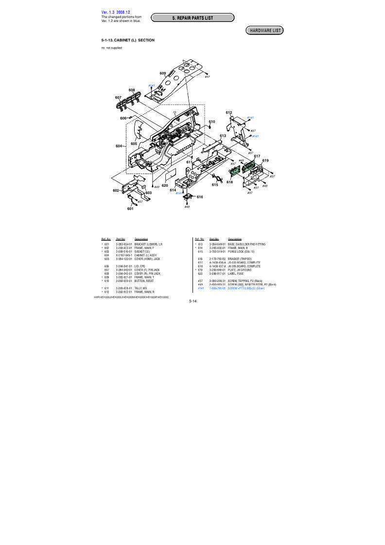
7/18/2019 SONY+HVR-HD1000 SERVICE MANUAL
http://slidepdf.com/reader/full/sonyhvr-hd1000-service-manual 109/425
4-60
HVR-HD1000J/HD1000U/HD1000N/HD1000E/HD1000P/HD1000C
DEWSENSOR
M902
LOADING MOTOR
S903
MODE SWITCH
M
(Dilect Solder)
(Dilect Solder)1
1 42
1-677-049- 11
1-867-810-
11
1-867-811- 12 21
12
29
1
FP-228 FLEXIBLE BOARD
FP-032 FLEXIBLE BOARD
FP-031 FLEXIBLE BOARD
S902
(REC PROOF)
MIC903
Q902
TAPE TOP SENSOR
4 PINCONNECTOR
Ver. 1.3 2008.12
The changed portions fromVer. 1.2 are shown in blue.
FP-228 (1 layer), FP-032 (1 layer), FP-031 (1 layer)
: Uses unleaded solder.
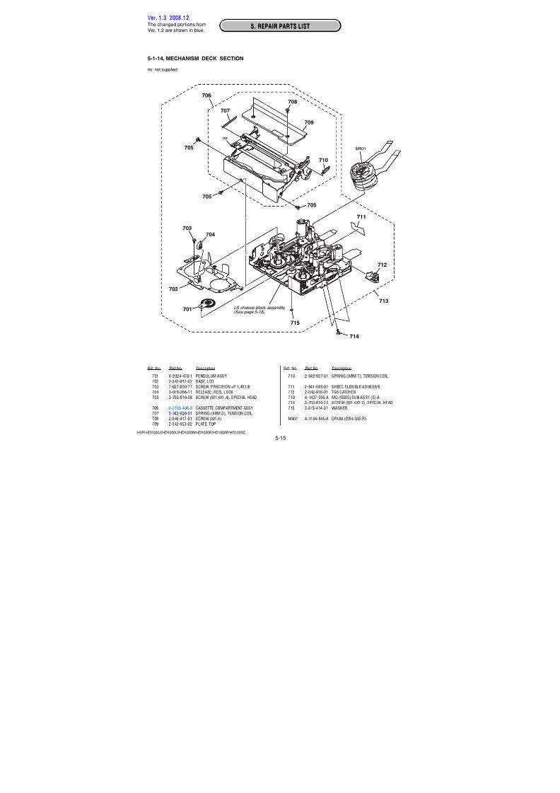
7/18/2019 SONY+HVR-HD1000 SERVICE MANUAL
http://slidepdf.com/reader/full/sonyhvr-hd1000-service-manual 110/425
NOTE
TO (2/2)TO (2/2)
HVR-HD1000J/HD1000U/HD1000N/HD1000E/HD1000P/HD1000C
Link Link
5. REPAIR PARTS LIST (1/2)
OVERALL SECTION-1 GRIP SECTION CABINET (R) SECTION OVERALL SECTION-2
LENS SECTION HANDLE (TALLY)SECTION VIEW FINDER SECTION LCD PANEL SECTION
EXPLODED VIEWSEXPLODED VIEWS
NOTE: Characters A to Z of the electrical parts list indicate location of exploded views in which the desired part is shown.
A B C D
E F HG
HANDLE (COVER)SECTION
I
OVERRALL SECTION-3
J
BATTERY PANEL SECTION
K
G BLOCK SECTION
L
CABINET (L) SECTION
M
MECHANISM DECKSECTION
N
LS/MECHANICHAL CHASSISBLOCK ASSEMBLY-1
O
LS/MECHANICHAL CHASSISBLOCK ASSEMBLY-1
P
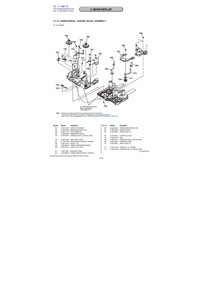
7/18/2019 SONY+HVR-HD1000 SERVICE MANUAL
http://slidepdf.com/reader/full/sonyhvr-hd1000-service-manual 111/425
NOTE
TO (1/2)TO (1/2)
HVR-HD1000J/HD1000U/HD1000N/HD1000E/HD1000P/HD1000C
NOTE: Characters A to Z of the electrical parts list indicate location of exploded views in which the desired part is shown.
Link Link ELECTRICAL PARTS LISTELECTRICAL PARTS LIST ACCESSORIES
BL-015 BOARD
BH-001 BOARD
BA-008 BOARD
DC-110 BOARD
CM-077 BOARD
FP-031 FLEXIBLE BOARD
FP-032 FLEXIBLE BOARD
EC-001 BOARD
FP-228 FLEXIBLE BOARD
FP-785 FLEXIBLE BOARD
FP-784 FLEXIBLE BOARD
FP-867 FLEXIBLE BOARD
JK-355 BOARD
HI-078 BOARD
MC-188 BOARD
LD-229 BOARD
JS-003 BOARD
HP-150 BOARD
IF-155 BOARD
SP-048 BOARD
MS-379 BOARD
NS-022 BOARD
PD-342 BOARD
RE-038 BOARD
MO-027 BOARD
VC-500 BOARD
US-014 BOARD
G
G
K
K
E
P
P
E
P
L
G
L
M
G
I
E
M
K
L
C
J
B
H
H
C
L
J
5. REPAIR PARTS LIST (2/2)
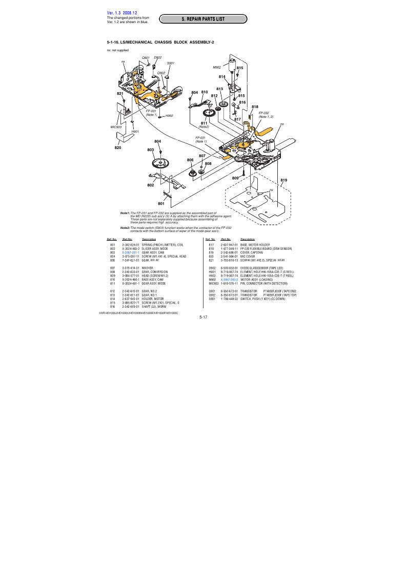
7/18/2019 SONY+HVR-HD1000 SERVICE MANUAL
http://slidepdf.com/reader/full/sonyhvr-hd1000-service-manual 112/425
5. REPAIR PARTS LIST
5-1
5. REPAIR PARTS LIST5. REPAIR PARTS LIST
HVR-HD1000J/HD1000U/HD1000N/HD1000E/HD1000P/HD1000C
(ENGLISH)NOTE:• -XX, -X mean standardized parts, so they may have some differences from
the original one.• Items marked “*” are not stocked since they are seldom required for routine
service. Some delay should be anticipated when ordering these items.
• The mechanical parts with no reference number in the exploded views are not
supplied.• Due to standardization, replacements in the parts list may be different from
the parts specified in the diagrams or the components used on the set.
• CAPACITORS:
uF: µF
• COILSuH: µH
• RESISTORS
All resistors are in ohms.
METAL: metal-film resistorMETAL OXIDE: Metal Oxide-film resistor
F: nonflammable
• SEMICONDUCTORS
In each case, u: µ, for example:uA...: µA... , uPA... , µPA... ,
uPB... , µPB... , uPC... , µPC... ,
uPD..., µPD...
When indicating parts by reference number,please include the board name.
(JAPANESE)
The components identified by mark 0 o rdotted line with mark0 are critical for safety.Replace only with part number specified.
Les composants identifiés par une marque0 sont critiques pour la sécurité.Ne les remplacer que par une pièce portantle numéro spécifié.
•
•
• *•
•
• •
00
• Color Indication of Appearance Parts
Example:
(SILVER) : Cabinet’s Color
(Silver) : Parts Color
•
• Abbreviation
AR : Argentine modelAUS : Australian model
BR : Brazilian model
CH : Chinese model
CND : Canadian model
EE : East European modelHK : Hong Kong model
J : Japanese model
JE : Tourist modelKR : Korea model
NE : North European model
Ver. 1.3 2008.12
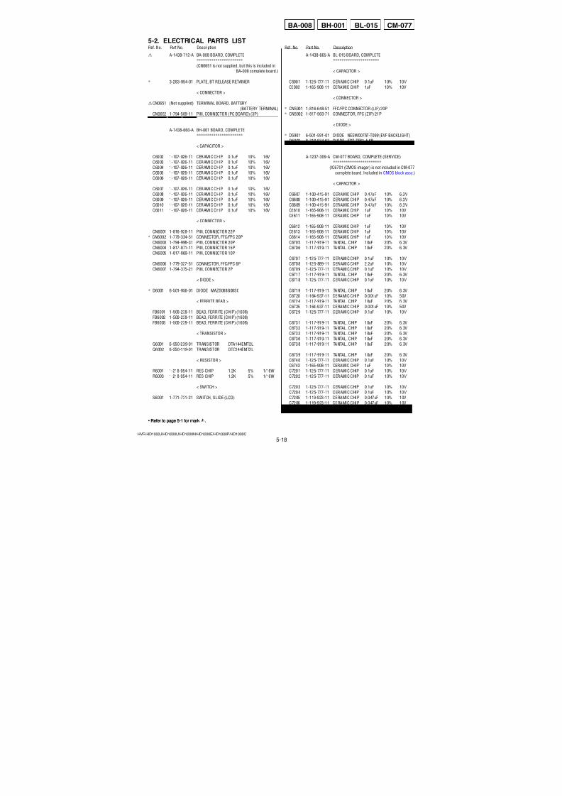
7/18/2019 SONY+HVR-HD1000 SERVICE MANUAL
http://slidepdf.com/reader/full/sonyhvr-hd1000-service-manual 113/4255-2
5. REPAIR PARTS LIST5. REPAIR PARTS LIST
HVR-HD1000J/HD1000U/HD1000N/HD1000E/HD1000P/HD1000C
DISASSEMBLY HARDWARE LIST
Ref. No. Part No. Description Ref. No. Part No. Description
1 3-284-044-01 BASE, GRIP
* 2 3-284-047-01 BRACKET (F), GRIP BELT
3 3-284-046-01 FRAME, GRIP
4 1-834-808-11 CABLE, FLEXIBLE FLAT (FFC-337)
5 X-2187-984-1 PAD ASSY, SHOULDER
6 3-284-050-01 SHEET (JAPAN) (HD1000U)
6 3-284-050-11 SHEET (JAPAN) (HD1000N)
6 3-284-050-21 SHEET (JAPAN) (HD1000P)
6 3-284-050-31 SHEET (JAPAN) (HD1000E)
6 3-284-050-41 SHEET (JAPAN) (HD1000C)
6 3-284-050-51 SHEET (JAPAN) (HD1000J)
#37 3-080-206-31 SCREW, TAPPING, P2 (Black)
#49 2-630-005-31 SCREW (M2), NEW TRUSTER, P2 (Black)#100 3-080-203-51 SREW (M2), LOCK ACE, P2 (Black)
#103 7-685-794-09 SCREW +PTT 2.6X10 (S) (Silver)
#104 7-682-548-09 SCREW +B 3X8 (Black)
5-1-1. OVERALL SECTION-1
5-1. EXPLODED VIEWS
#37
#100
#100
#100
#104
#100
#103
#49
#49
#37
Grip Section (See Page 5-3)
Cabinet (R) Section (See Page 5-4)
Overall Section-2 (See Page 5-5)
1
56
2
3
4
Ver. 1.3 2008.12The changed portions fromVer. 1.2 are shown in blue.
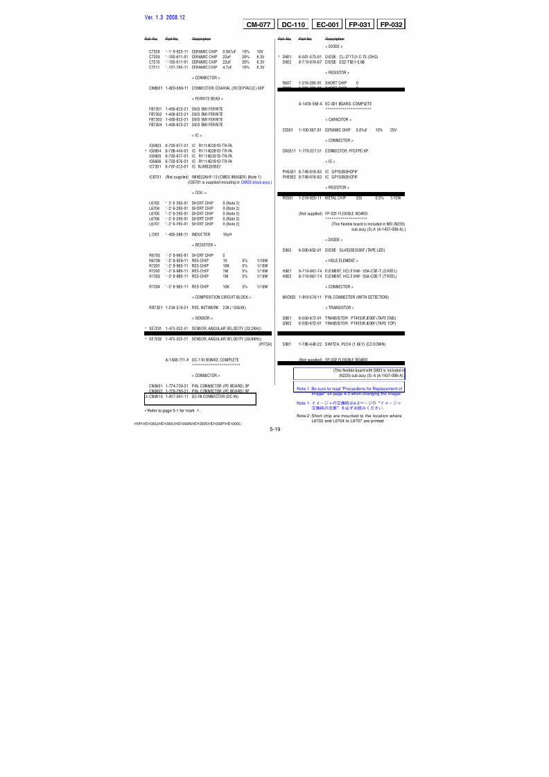
7/18/2019 SONY+HVR-HD1000 SERVICE MANUAL
http://slidepdf.com/reader/full/sonyhvr-hd1000-service-manual 114/4255-3
5. REPAIR PARTS LIST5. REPAIR PARTS LIST
HVR-HD1000J/HD1000U/HD1000N/HD1000E/HD1000P/HD1000C
HARDWARE LIST
Ref. No. Part No. Description Ref. No. Part No. Description51 X-2187-973-1 CABINET ASSY, GRIP
52 3-289-560-01 BELT, GRIP
53 1-480-479-11 SWITCH BLOCK, CONTROL (ZM90500)
54 3-283-958-01 BRACKET (B), GRIP BELT
55 1-480-480-11 SWITCH BLOCK, CONTROL (PS90500)
* 56 3-283-959-01 PLATE, SS RETAINER
57 A-1438-618-A NS-022 BOARD, COMPLETE
#37 3-080-206-31 SCREW, TAPPING, P2 (Black)
5-1-2. GRIP SECTION
51
52
#37
#37
#37
#37
53
54
55
56
57
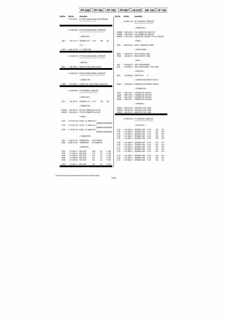
7/18/2019 SONY+HVR-HD1000 SERVICE MANUAL
http://slidepdf.com/reader/full/sonyhvr-hd1000-service-manual 115/4255-4
5. REPAIR PARTS LIST5. REPAIR PARTS LIST
HVR-HD1000J/HD1000U/HD1000N/HD1000E/HD1000P/HD1000C
HARDWARE LIST
Ref. No. Part No. Description Ref. No. Part No. Description
101 3-283-972-01 RING, ORNAMENTAL
102 X-2187-974-1 CABINET (R) ASSY* 103 3-283-971-01 BRACKET (UPPER), LR
* 104 3-283-969-01 BRACKET, CHASSIS
105 1-834-807-11 CABLE, FLEXIBLE FLAT (FFC-336)
106 A-1438-625-A SP-048 BOARD, COMPLETE
107 A-1438-628-A MO-027 BOARD, COMPLETE
SP901 1-825-262-62 LOUD SPEAKER (1.6CM)#37 3-080-206-31 SCREW, TAPPING, P2 (Black)
#49 2-630-005-31 SCREW (M2), NEW TRUSTER, P2 (Black)
#105 2-891-494-31 SCREW (M2), NEW TRUSTER, P2 (Red)
5-1-3. CABINET (R) SECTION
ns: not supplied
#49
#37
#37
#37
ns
SP901#105
MO-02
7#37
101
102103
104
105 106
107
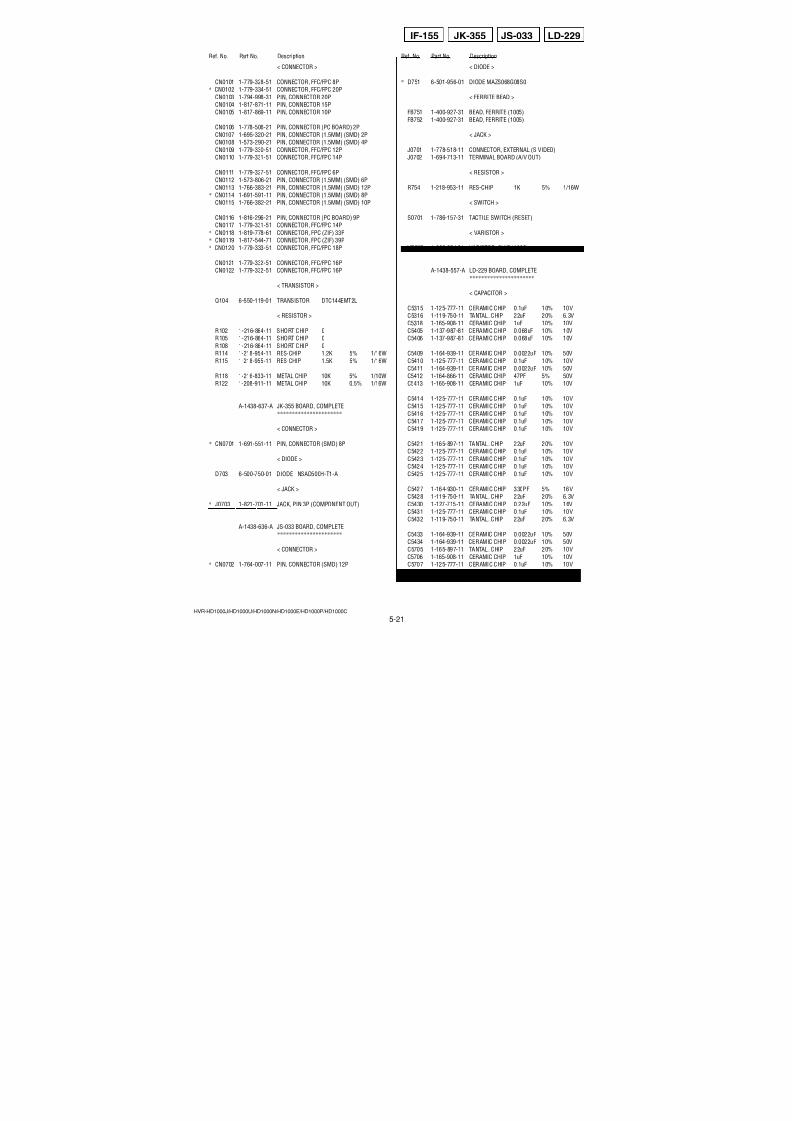
7/18/2019 SONY+HVR-HD1000 SERVICE MANUAL
http://slidepdf.com/reader/full/sonyhvr-hd1000-service-manual 116/4255-5
5. REPAIR PARTS LIST5. REPAIR PARTS LIST
HVR-HD1000J/HD1000U/HD1000N/HD1000E/HD1000P/HD1000C
DISASSEMBLY HARDWARE LIST
Ref. No. Part No. Description Ref. No. Part No. Description
151 1-834-811-11 CABLE, FLEXIBLE FLAT (FFC-340)
152 1-965-558-11 HARNESS (LI-062)
* 153 3-284-037-01 FRAME (R)
154 CAUTION TAPE AS
#49 2-630-005-31 SCREW (M2), NEW TRUSTER, P2 (Black)
5-1-4. OVERALL SECTION-2
#49
#49
#49
Handle (Tally) Section (See Page 5-7)
Lens Section (See Page 5-6)
154(9mm x 28mm)151
152
153
CAUTION:For the part of 154, cut SHEET, LENS FLEXIBLE (3-052-196-01) into the desired length and use it.
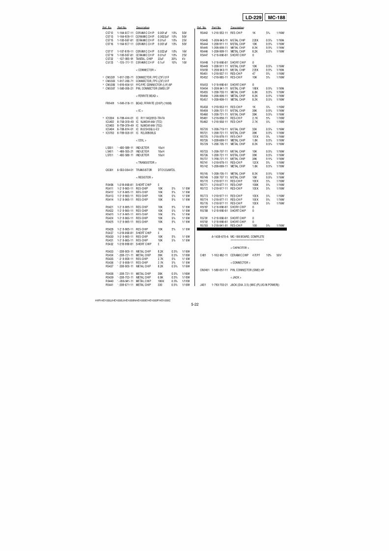
7/18/2019 SONY+HVR-HD1000 SERVICE MANUAL
http://slidepdf.com/reader/full/sonyhvr-hd1000-service-manual 117/4255-6
5. REPAIR PARTS LIST5. REPAIR PARTS LIST
HVR-HD1000J/HD1000U/HD1000N/HD1000E/HD1000P/HD1000C
HARDWARE LIST
Ref. No. Part No. Description Ref. No. Part No. Description
201 X-2187-983-1 PANEL ASSY, F
202 A-1438-558-A EC-001 BOARD, COMPLETE
203 1-834-810-11 CABLE, FLEXIBLE FLAT (FFC-339)
* 204 3-284-035-01 FRAME (L) (905) LENS
205 A-1227-735-A LSV-1190A (SERVICE)
206 1-788-558-11 FILTER BLOCK, OPTICAL
207 2-698-010-01 RUBBER (1190), SEAL
208 A-1209-688-A CMOS BLOCK ASSY (CMOS IMAGER) (Note)
209 A-1237-309-A CM-077 BOARD, COMPLETE (SERVICE)
210 3-284-036-01 CLAMP, FLEXIBLE
* 211 3-284-034-01 FRAME (R (905)), LENS
212 A-1438-557-A LD-229 BOARD, COMPLETE
213 CAUTION TAPE AS#1 2-635-562-11 SCREW (M1.7) (Black)
#3 2-660-401-01 SCREW (M1.7), NEW TRU-STAR, P2 (Red)
#23 3-080-204-11 SCREW, TAPPING, P2 (Black)
#37 3-080-206-31 SCREW, TAPPING, P2 (Black)
5-1-5. LENS SECTION
ns: not supplied
201
ns (IC6701)
ns
ns
#23
#23
#23
#1
#1
#37
#37
#37
#37
L D - 2 2 9
CM-077
#3
202
203
204
205
206
207
208
(Note)
209
210
211
212
213
(9mm x 28mm)
Note: Be sure to read “Precautions for Replacement of
Imager” on page 4-3 when changing the imager.
CAUTION:
For the part of 213, cut SHEET, LENS FLEXIBLE (3-052-196-01) into the desired length and use it.
Ver. 1.3 2008.12
Note :
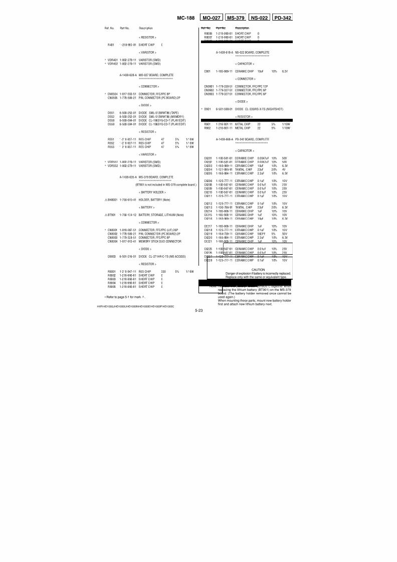
7/18/2019 SONY+HVR-HD1000 SERVICE MANUAL
http://slidepdf.com/reader/full/sonyhvr-hd1000-service-manual 118/4255-7
5. REPAIR PARTS LIST5. REPAIR PARTS LIST
HVR-HD1000J/HD1000U/HD1000N/HD1000E/HD1000P/HD1000C
DISASSEMBLY HARDWARE LIST
Ref. No. Part No. Description Ref. No. Part No. Description
251 X-2187-977-1 CABINET ASSY, TALLY (FRONT)
252 X-2187-986-1 HOLDER ASSY, MICROPHONE253 3-284-074-01 RUBBER, MICROPHONE HOLDER
254 3-284-081-01 SHEET, RUBBER ADHESIVE
255 3-284-080-01 RUBBER, MICROPHONE
256 3-283-989-01 BASE, RING
#23 3-080-204-11 SCREW, TAPPING, P2 (Black)
#37 3-080-206-31 SCREW, TAPPING, P2 (Black)#49 2-630-005-31 SCREW (M2), NEW TRUSTER, P2 (Black)
#53 3-080-206-21 SCREW, TAPPING, P2 (Black)
#102 7-621-284-30 SCREW +P 2.6X8 (Black)
5-1-6. HANDLE (TALLY) SECTION
ns: not supplied
251256
252 254
254
255
255
253
View Finder Section (See Page 5-8)
Handle (Cover) Section (See Page 5-10)
#37
#102
#53
#23
#49
#49
#49
#49
ns
ns
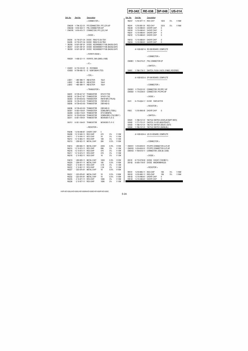
7/18/2019 SONY+HVR-HD1000 SERVICE MANUAL
http://slidepdf.com/reader/full/sonyhvr-hd1000-service-manual 119/4255-8
5. REPAIR PARTS LIST5. REPAIR PARTS LIST
HVR-HD1000J/HD1000U/HD1000N/HD1000E/HD1000P/HD1000C
DISASSEMBLY HARDWARE LIST
Ref. No. Part No. Description Ref. No. Part No. Description
301 X-2187-981-1 CABINET (UPPER) ASSY, VF
302 3-284-016-01 COVER, HINGE (LOWER)
303 A-1438-659-A FP-784 FLEXIBLE BOARD, COMPLETE
* 304 3-284-017-01 FRAME, VF
305 A-1438-660-A BH-001 BOARD, COMPLETE
* 306 3-284-015-01 FRAME, HI
307 A-1438-658-A HI-078 BOARD, COMPLETE
308 X-2187-979-1 HINGE ASSY, VF
309 1-965-791-11 HARNESS (BI-001)
310 1-834-809-11 CABLE, FLEXIBLE FLAT (FFC-338)
311 A-1438-665-A BL-015 BOARD, COMPLETE
312 2-664-672-01 GUIDE, LAMP
* 313 2-638-819-01 CUSHION, LCD
* 314 2-638-818-01 ILLUMINATOR
* 315 2-638-816-01 PLATE (TFT), DEFLECTION
316 2-664-671-01 SPACER, LCD
* 317 2-699-236-01 CABINET (222), INNER
318 3-284-124-01 CABINET, VF INNER
319 X-2187-978-1 CABINET (LOWER) ASSY, VF
* 320 3-283-991-01 KNOB, ON/OFF
* 321 3-283-992-01 RETAINER, ON/OFF KNOB
322 X-2187-980-1 ADJUSTMENT ASSY, VISIBILITY
323 1-500-930-11 CORE, FERRITE
LCD902 8-753-241-14 LCX076AKE-1
#23 3-080-204-11 SCREW, TAPPING, P2 (Black)
#37 3-080-206-31 SCREW, TAPPING, P2 (Black)
#49 2-630-005-31 SCREW (M2), NEW TRUSTER, P2 (Black)
#105 2-891-494-31 SCREW (M2), NEW TRUSTER, P2 (Red)
5-1-7. VIEW FINDER SECTION
ns: not supplied
301
302
303
304
305
306
307
308
309
323
LCD Panel Section (See Page 5-9)
#49
#49
#37
#37
#37
#37
#37
#37
ns
#23 #105
#105
LCD902
#105
310
311312313
314315
316
318
322
319
320
321
317
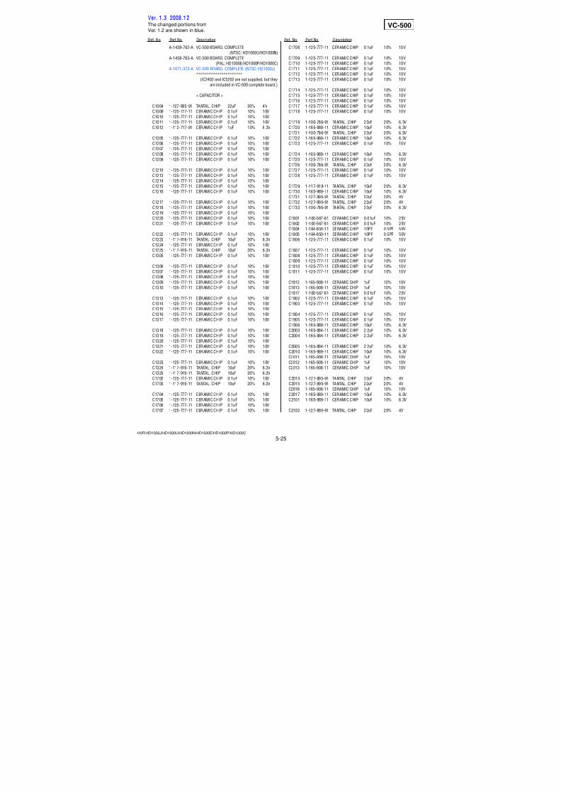
7/18/2019 SONY+HVR-HD1000 SERVICE MANUAL
http://slidepdf.com/reader/full/sonyhvr-hd1000-service-manual 120/4255-9
5. REPAIR PARTS LIST5. REPAIR PARTS LIST
HVR-HD1000J/HD1000U/HD1000N/HD1000E/HD1000P/HD1000C
HARDWARE LIST
Ref. No. Part No. Description Ref. No. Part No. Description
351 A-1438-667-A RE-038 BOARD, COMPLETE
352 1-965-560-11 HARNESS (RS-112)
353 3-284-024-01 COVER (REAR), HINGE
354 CAUTION SHEET (MAGNET), ADHESIVE
355 1-452-929-12 MAGNET (011)
356 X-2187-982-1 HINGE ASSY
357 1-965-550-11 HARNESS (HP-147)
358 3-284-023-01 COVER (FRONT), HINGE
359 3-284-028-01 CABINET (M), P
* 360 3-284-026-01 PLATE (P), GROUND
361 3-284-027-01 CUSHION, TP
362 2-887-999-01 FRONT FRAME (2.7J)
363 2-666-802-01 PRISM SHEET V (2.7)
364 2-666-803-01 PRISM SHEET H (2.7)
365 2-666-804-01 DIFFUSION SHEET (2.7)
366 2-666-807-21 AG SHEET (2.7)
367 2-666-801-01 LIGHT GUIDE (2.7)
368 2-894-347-01 REFLECTION SHEET (2.7J)
369 A-1438-668-A PD-342 BOARD, COMPLETE
* 370 2-638-780-01 CLIP
371 3-284-029-01 GUARD, FLEXIBLE
372 3-284-025-01 CABINET (C), P
LCD901 A-1228-786-A TP BLOCK ASSY (27ESHGU07)#23 3-080-204-11 SCREW, TAPPING, P2 (Black)
#49 2-630-005-31 SCREW (M2), NEW TRUSTER, P2 (Black)
#105 2-891-494-31 SCREW (M2), NEW TRUSTER, P2 (Red)
5-1-8. LCD PANEL SECTION
#105
#49
#23
#49
LCD901
#49
351
352355
353
354(2.2mm x 3mm)
356
357
358
359
360
361
362
363
364
365
366
369
370
P D - 3 4 2
367
368
371
372
CAUTION:For the part of 354, cut SHEET, ADHESIVE (2-649-300-01) into the desired length and use it.
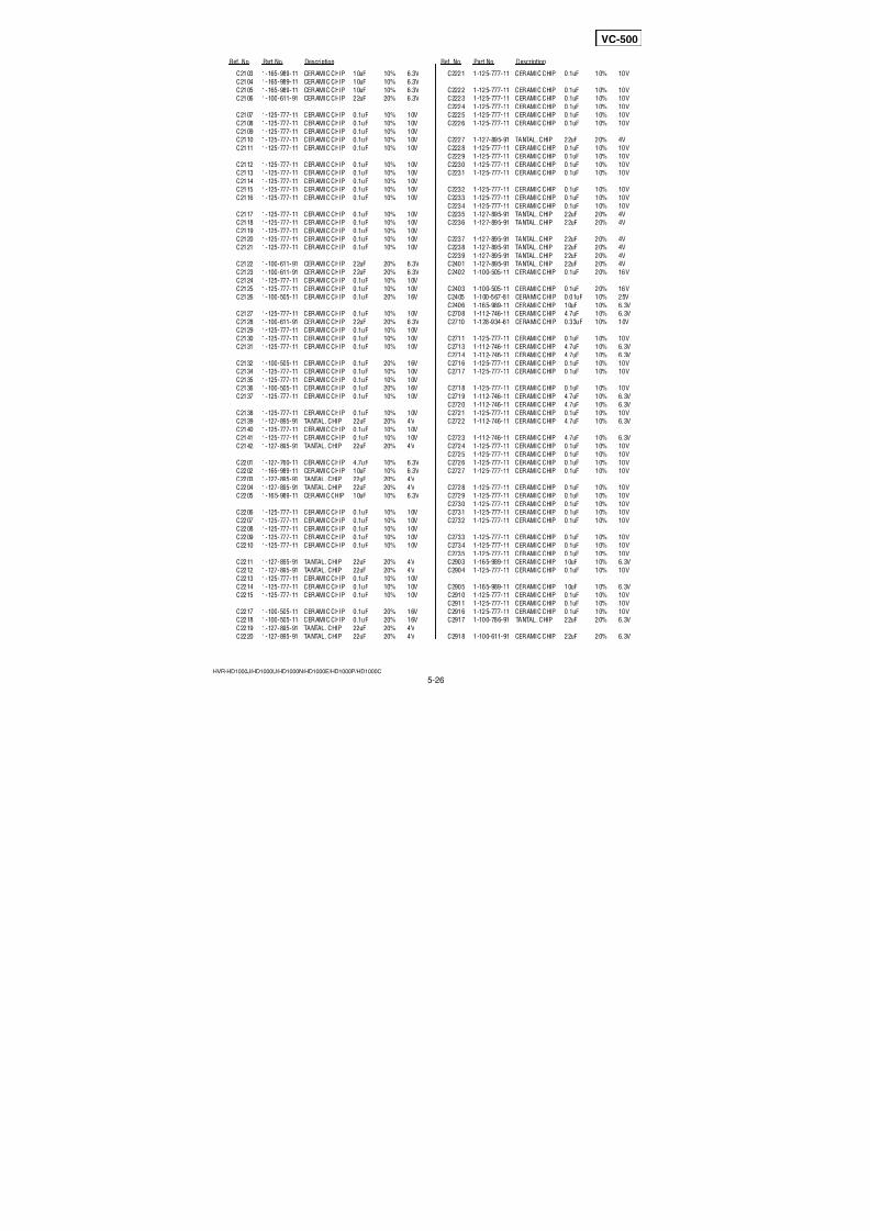
7/18/2019 SONY+HVR-HD1000 SERVICE MANUAL
http://slidepdf.com/reader/full/sonyhvr-hd1000-service-manual 121/4255-10
5. REPAIR PARTS LIST5. REPAIR PARTS LIST
HVR-HD1000J/HD1000U/HD1000N/HD1000E/HD1000P/HD1000C
DISASSEMBLY HARDWARE LIST
Ref. No. Part No. Description Ref. No. Part No. Description
* 401 3-283-987-01 BRACKET, TALLY
402 3-283-986-01 CABINET, TALLY (LR)
403 3-283-984-01 COVER, HANDLE LOWER
404 A-1438-670-A MC-188 BOARD, COMPLETE
* 405 3-283-985-01 BRACKET, MICROPHONE JACK
406 1-965-549-11 HARNESS (MI-075)
407 1-874-532-11 FP-793 FLEXIBLE BOARD
* 408 2-892-090-01 KEY, RUBBER TACT
409 X-2187-976-1 COVER ASSY, HANDLE
410 3-067-469-11 SHOE, ACCESSORY
* 411 3-283-980-01 PLATE (B), HANDLE
412 X-2187-975-1 HANDLE ASSY
413 3-283-983-01 BRACKET (R), STRAP
* 414 3-283-979-01 PLATE (A), HANDLE
* 415 3-283-981-01 PLATE (C), HANDLE
416 3-283-982-01 BRACKET (F), STRAP
417 1-834-802-11 CABLE, FLEXIBLE FLAT (FFC-329)
#23 3-080-204-11 SCREW, TAPPING, P2 (Black)
#37 3-080-206-31 SCREW, TAPPING, P2 (Black)
#49 2-630-005-31 SCREW (M2), NEW TRUSTER, P2 (Black)
#100 3-080-203-51 SREW (M2), LOCK ACE, P2 (Black)
#105 2-891-494-31 SCREW (M2), NEW TRUSTER, P2 (Red)
#106 3-713-786-11 SCREW (M2X6) (Black)
#107 3-032-750-01 (+) K SCREW M2 (Silver)
5-1-9. HANDLE (COVER) SECTION
ns: not supplied
#106
#49
#23
#105
#49
#49
#49
#100
#100 #49
#49
#49 #49
#49
#49
#49
#37 #107
#107
ns
#37
#106 #37
401
402
403
404
406
407
408
409
410
405
Overall Section-3 (See Page 5-11)
410
411
412
413
414416
415
417
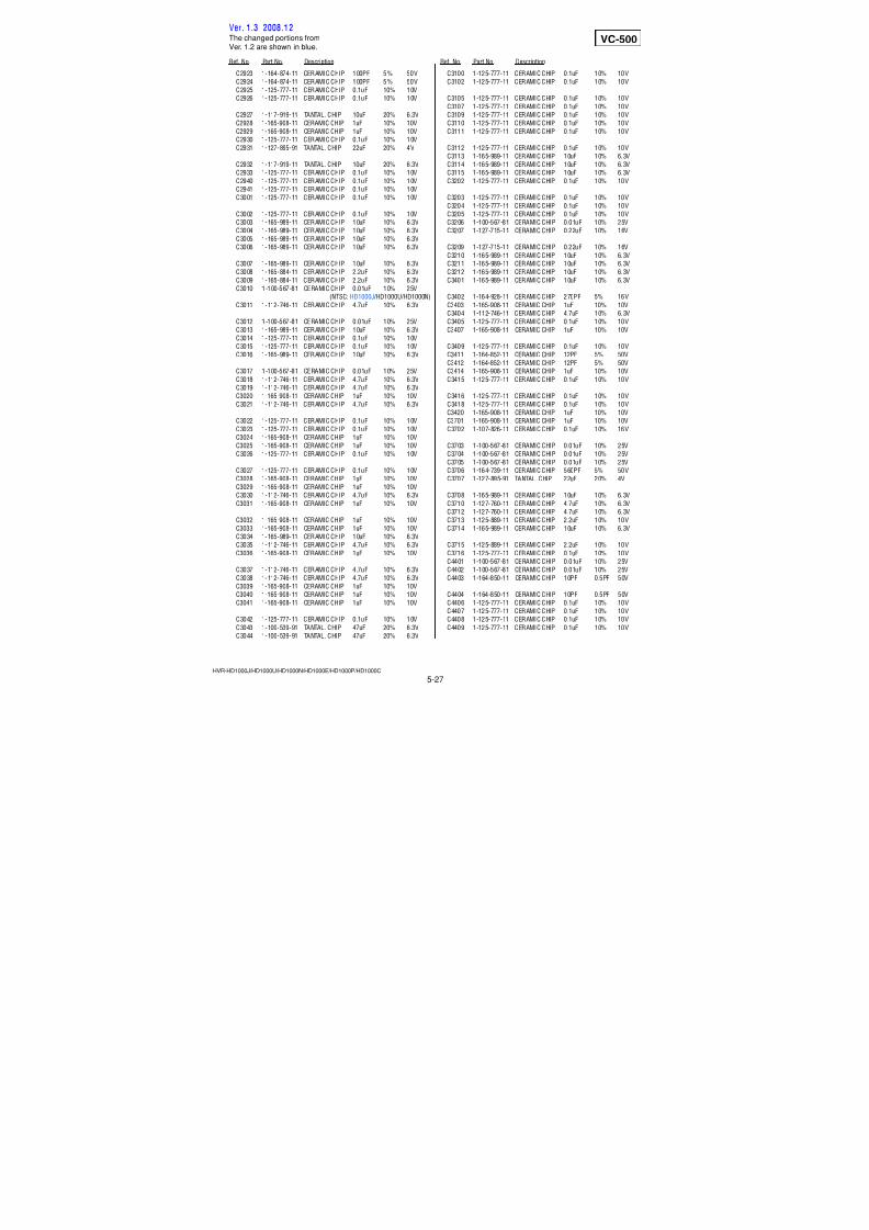
7/18/2019 SONY+HVR-HD1000 SERVICE MANUAL
http://slidepdf.com/reader/full/sonyhvr-hd1000-service-manual 122/4255-11
5. REPAIR PARTS LIST5. REPAIR PARTS LIST
HVR-HD1000J/HD1000U/HD1000N/HD1000E/HD1000P/HD1000C
DISASSEMBLY HARDWARE LIST
Ref. No. Part No. Description Ref. No. Part No. Description
* 451 3-283-936-01 BRACKET, MS
452 A-1438-635-A MS-379 BOARD, COMPLETE
* 453 3-283-935-01 BRACKET, USB
454 1-833-788-11 CABLE, FLEXIBLE FLAT (FFC-107)
455 A-1438-634-A US-014 BOARD, COMPLETE
456 1-965-572-11 HARNESS (MI-076)
457 X-2187-985-1 DOOR ASSY, MD458 1-965-745-11 HARNESS (BD-058)
459 1-965-556-11 HARNESS (IJ-001)
460 1-965-557-11 HARNESS (IJ-002)
461 1-965-554-11 HARNESS (DI-003)
462 1-965-555-11 HARNESS (DI-004)
463 1-965-559-11 HARNESS (DI-005)
464 1-543-793-11 FILTER, CLAMP (FERRITE CORE)
0BH8001 1-756-615-41 HOLDER, BATTERY
0BT901 1-756-134-12 BATTERY, STORAGE, LITHIUM
#1 2-635-562-11 SCREW (M1.7) (Black)
#3 2-660-401-01 SCREW (M1.7), NEW TRU-STAR, P2 (Red)#37 3-080-206-31 SCREW, TAPPING, P2 (Black)
#49 2-630-005-31 SCREW (M2), NEW TRUSTER, P2 (Black)
#105 2-891-494-31 SCREW (M2), NEW TRUSTER, P2 (Red)
• Refer to page 5-1 for mark 0.
5-1-10. OVERALL SECTION-3
ns: not supplied
BH8001(Note)
BT901(Note)
ns
ns
#37
#37
#37
#49
#49
#49
#49 #1
#37
#37
#37
#105
#3
459
460
461
462
463
464
451
452
454
453
455
456
458
! : BT901 (BATTERY, STORAGE,
LITHIUM)Board on the mount position.(See page 4-56)
457
Cabinet (L) Section
(See Page 5-14)G Block Section (See Page 5-13)
Battery Panel Section (See Page 5-12)
CAUTIONDanger of explosion if battery is incorrectly replaced.Replace only with the same or equivalent type.
Note: Replace the battery holder (BH8001) together whenreplacing the lithium battery (BT901) on the MS-379board. (The battery holder removed once cannot be
used again.)When mounting these parts, mount new battery holderfirst and attach new lithium battery next.
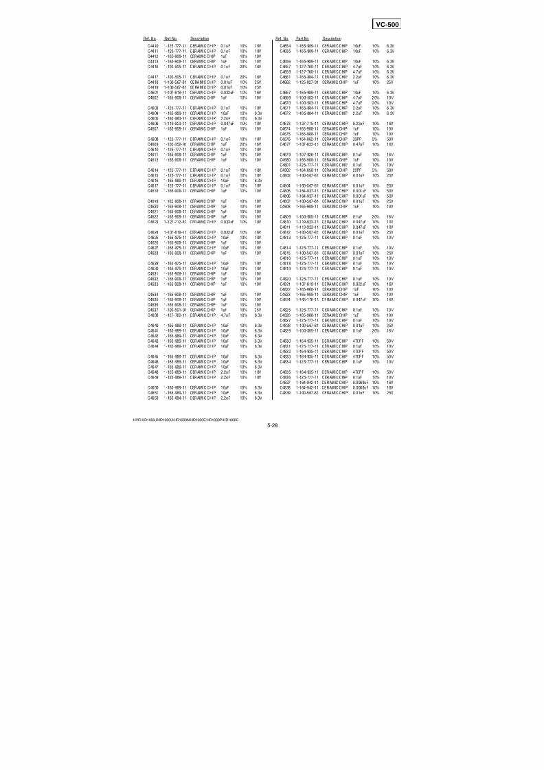
7/18/2019 SONY+HVR-HD1000 SERVICE MANUAL
http://slidepdf.com/reader/full/sonyhvr-hd1000-service-manual 123/4255-12
5. REPAIR PARTS LIST5. REPAIR PARTS LIST
HVR-HD1000J/HD1000U/HD1000N/HD1000E/HD1000P/HD1000C
HARDWARE LIST
Ref. No. Part No. Description Ref. No. Part No. Description
* 501 3-283-953-01 PLATE, DC TERMINAL RETAINER
502 A-1438-711-A DC-110 BOARD, COMPLETE
503 A-1438-710-A HP-150 BOARD, COMPLETE* 504 3-283-952-01 PLATE, HP TERMINAL RETAINER
505 X-2187-972-1 PANEL ASSY, JACK
0506 A-1438-712-A BA-008 BOARD, COMPLETE
507 3-284-038-01 COVER (DC), JACK
508 3-284-039-01 COVER (HP), JACK
509 3-284-040-01 COVER (LANC), JACK
510 X-2187-971-1 PANEL ASSY, BT
511 3-060-595-01 CLAW, BT LOCK
* 512 3-283-954-01 PLATE, BT RELEASE RETAINER
#37 3-080-206-31 SCREW, TAPPING, P2 (Black)
#105 2-891-494-31 SCREW (M2), NEW TRUSTER, P2 (Red)
5-1-11. BATTERY PANEL SECTION
ns: not supplied
501
502
503
#37
#37
#37
#37
#105 #105
ns
ns
ns
ns
ns ns
ns
504
505
506
507
508
509
510
511
512
ns (CN0651)
• Refer to page 5-1 for mark 0.
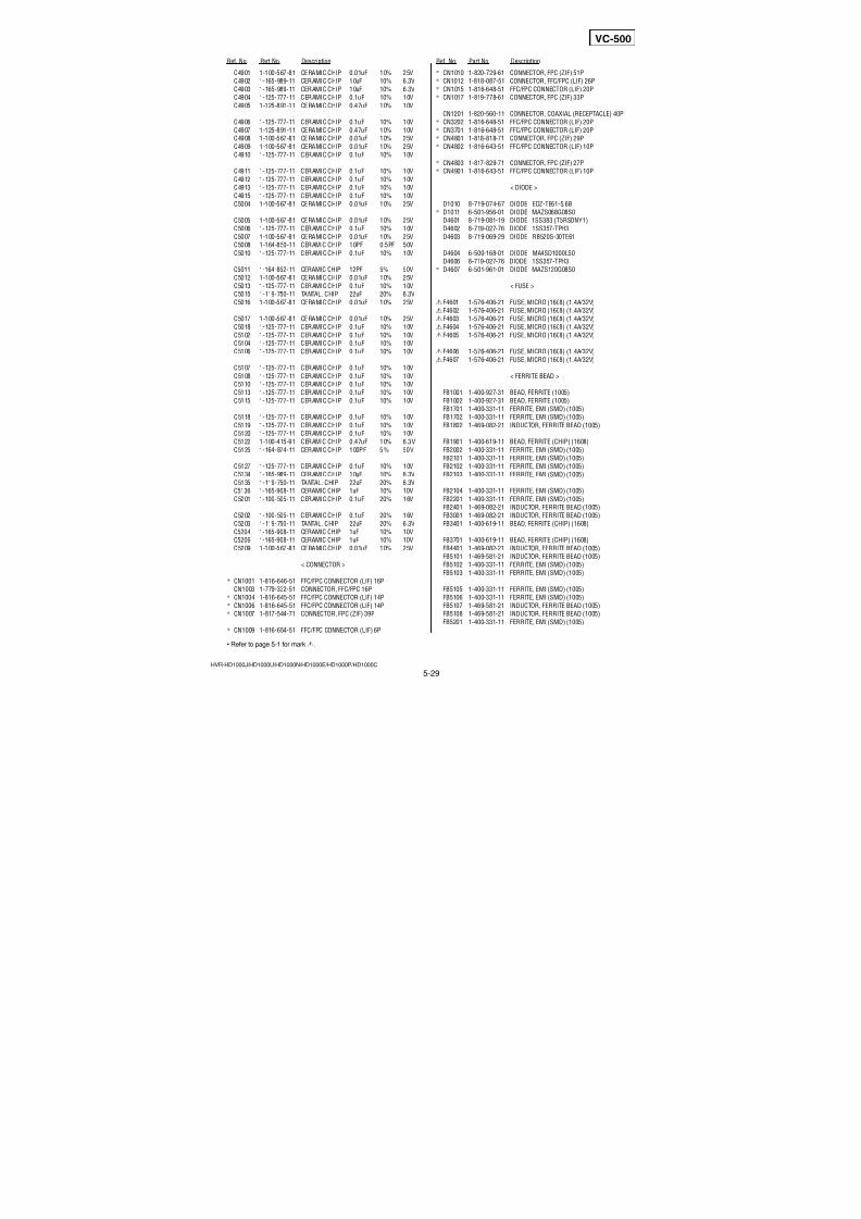
7/18/2019 SONY+HVR-HD1000 SERVICE MANUAL
http://slidepdf.com/reader/full/sonyhvr-hd1000-service-manual 124/4255-13
5. REPAIR PARTS LIST5. REPAIR PARTS LIST
HVR-HD1000J/HD1000U/HD1000N/HD1000E/HD1000P/HD1000C
DISASSEMBLY HARDWARE LIST
Ref. No. Part No. Description Ref. No. Part No. Description
551 1-834-804-11 CABLE, FLEXIBLE FLAT (FFC-332)
552 1-834-803-11 CABLE, FLEXIBLE FLAT (FFC-330)
553 1-874-325-11 FP-789 FLEXIBLE BOARD
554 1-874-324-11 FP-788 FLEXIBLE BOARD
555 1-834-806-11 CABLE, FLEXIBLE FLAT (FFC-335)
556 1-834-805-11 CABLE, FLEXIBLE FLAT (FFC-334)
557 A-1438-674-A IF-155 BOARD, COMPLETE
* 558 3-283-946-01 HOLDER, IF
559 1-874-323-11 FP-787 FLEXIBLE BOARD* 560 3-283-943-01 BRACKET, HDMI
561 1-965-571-11 HARNESS (HN-047)
562 A-1438-762-A VC-500 BOARD, COMPLETE
(NTSC: HD1000U/HD1000N)
562 A-1438-763-A VC-500 BOARD, COMPLETE
(PAL: HD1000E/HD1000P/HD1000C)
562 A-1671-373-A VC-500 BOARD, COMPLETE (NTSC: HD1000J)
563 X-2187-970-1 FRAME ASSY (905), MD
564 A-1438-676-A FP-785 FLEXIBLE BOARD, COMPLETE
565 1-874-322-11 FP-786 FLEXIBLE BOARD
566 A-1438-675-A FP-867 FLEXIBLE BOARD, COMPLETE
* 567 3-291-065-01 HEAT SINK, VC
#1 2-635-562-11 SCREW (M1.7) (Black)
#3 2-660-401-01 SCREW (M1.7), NEW TRU-STAR, P2 (Red)
#15 3-062-214-01 SCREW (M1.4X1.5) (Si lver)
#37 3-080-206-31 SCREW, TAPPING, P2 (Black)
#49 2-630-005-31 SCREW (M2), NEW TRUSTER, P2 (Black)
5-1-12. G BLOCK SECTION
ns: not supplied
551
552
551558
559
561
562
563
567
564
565
566 560
VC-50
0
Mechanism Deck Section (See Page 5-15)
#37
#49
#49
#49
#3
#3
#15
#1
#1
ns
ns
553554555
556
557
Ver. 1.3 2008.12
The changed portions fromVer. 1.2 are shown in blue.
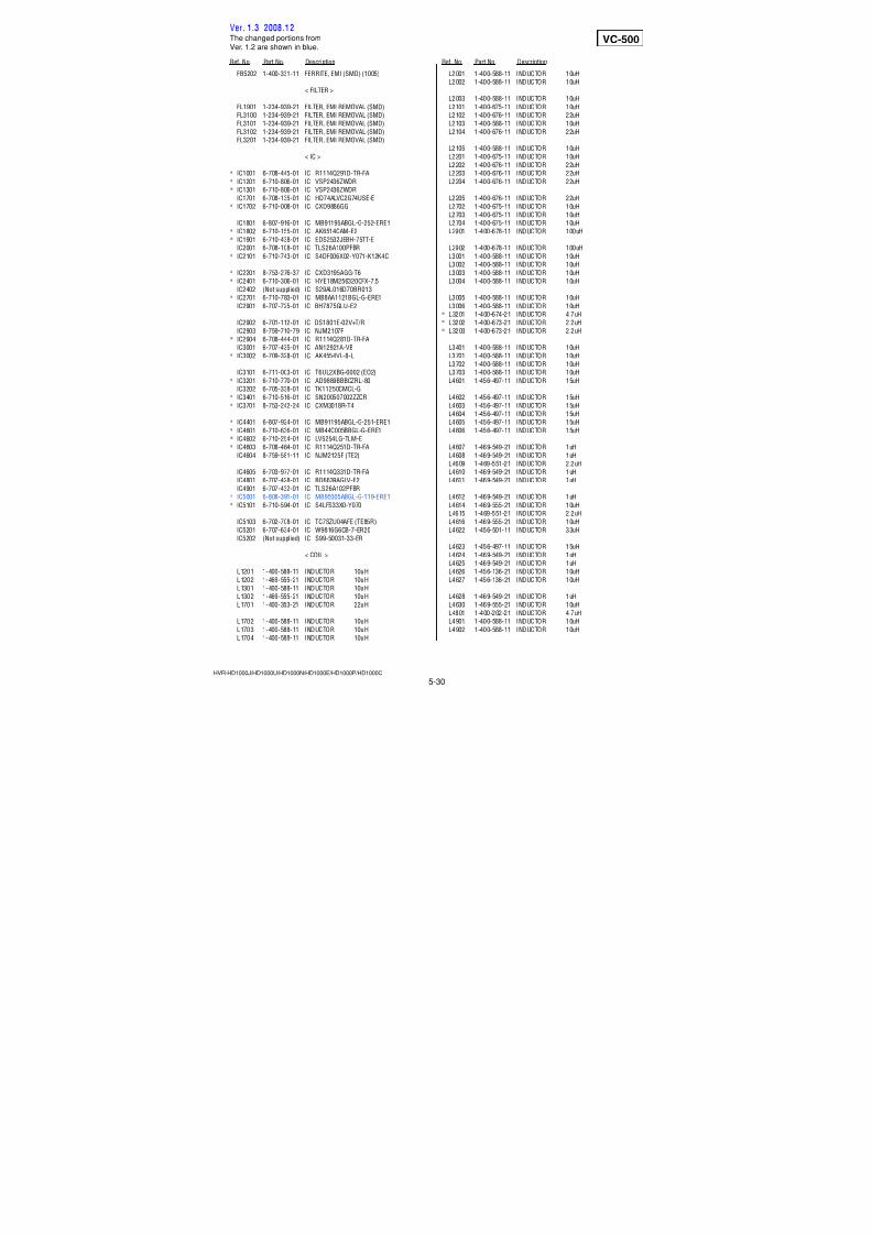
7/18/2019 SONY+HVR-HD1000 SERVICE MANUAL
http://slidepdf.com/reader/full/sonyhvr-hd1000-service-manual 125/4255-14
5. REPAIR PARTS LIST5. REPAIR PARTS LIST
HVR-HD1000J/HD1000U/HD1000N/HD1000E/HD1000P/HD1000C
HARDWARE LIST
Ref. No. Part No. Description Ref. No. Part No. Description
* 601 3-283-934-01 BRACKET (LOWER), LR
* 602 3-283-933-01 FRAME, MAIN, F
* 603 3-289-516-01 GASKET (LE)
604 X-2187-545-1 CABINET (L) ASSY
605 3-284-122-01 COVER (HDMI), JACK
606 3-284-041-01 LID, CPC
607 3-284-042-01 COVER (F), PIN JACK
608 3-284-043-01 COVER (R), PIN JACK
* 609 3-283-931-01 FRAME, MAIN, T
* 610 3-283-939-01 BUTTON, RESET
* 611 3-283-938-01 TALLY, MS
* 612 3-283-932-01 FRAME, MAIN, R
* 613 3-284-049-01 BASE, SHOULDER PAD FITTING
* 614 3-283-930-01 FRAME, MAIN, B
615 3-703-319-01 PURSE LOCK (DIA.15)
616 2-178-793-02 BRACKET (TRIPOD)
617 A-1438-636-A JS-033 BOARD, COMPLETE
618 A-1438-637-A JK-355 BOARD, COMPLETE
* 619 3-283-940-01 PLATE, JK GROUND
620 3-286-017-01 LABEL, FUSE
#37 3-080-206-31 SCREW, TAPPING, P2 (Black)
#49 2-630-005-31 SCREW (M2), NEW TRUSTER, P2 (Black)
#141 7-685-791-01 SCREW +PTT 2.6X5 (S) (Silver)
5-1-13. CABINET (L) SECTION
ns: not supplied
601
602603
604605
606
607
#37
#37
#37
#37
#37
#37
#37
#37
#141
#141
#141
#141
#49
#49
#49 #49
ns
608
609
610
613
612
611
614
620 615
616
617
618
619
Ver. 1.3 2008.12The changed portions fromVer. 1.2 are shown in blue.
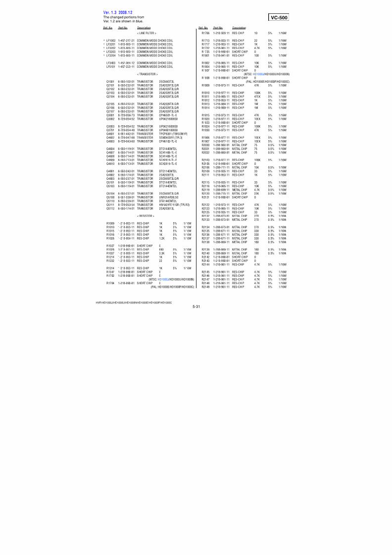
7/18/2019 SONY+HVR-HD1000 SERVICE MANUAL
http://slidepdf.com/reader/full/sonyhvr-hd1000-service-manual 126/4255-15
5. REPAIR PARTS LIST5. REPAIR PARTS LIST
HVR-HD1000J/HD1000U/HD1000N/HD1000E/HD1000P/HD1000C
Ref. No. Part No. Description Ref. No. Part No. Description
701 X-2024-478-1 PENDULUM ASSY
702 2-342-917-02 BASE, LED
703 7-627-850-77 SCREW, PRECISION +P 1.4X1.8
704 3-079-366-11 RELEASE, REEL LOCK
705 3-703-816-08 SCREW (M1.4X1.4), SPECIAL HEAD
706 X-2103-406-3 CASSETTE COMPARTMENT ASSY
707 2-342-926-01 SPRING (ARM S), TENSION COIL
708 2-546-417-01 SCREW (M1.4)
709 2-342-933-02 PLATE, TOP
710 2-342-927-01 SPRING (ARM T), TENSION COIL
711 2-541-585-01 SHEET, FLEXIBLE ADHESIVE
712 2-342-918-01 TG6 CATCHER
713 A-1437-006-A MD (N220) SUB ASSY (S) A714 3-703-816-13 SCREW (M1.4X2.0), SPECIAL HEAD
715 3-315-414-31 WASHER
M901 A-1154-545-A DRUM (DEH-33E-R)
5-1-14. MECHANISM DECK SECTION
ns: not supplied
M901
LS chassis block assembly (See page 5-16)
708
703704
701
ns
714
715
712
713
711
705
705
705
709
710
707
702
706
Ver. 1.3 2008.12The changed portions fromVer. 1.2 are shown in blue.
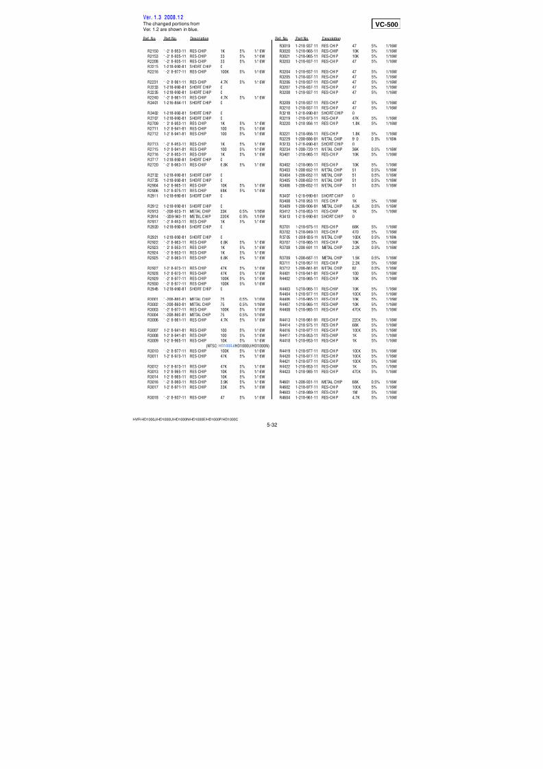
7/18/2019 SONY+HVR-HD1000 SERVICE MANUAL
http://slidepdf.com/reader/full/sonyhvr-hd1000-service-manual 127/4255-16
5. REPAIR PARTS LIST5. REPAIR PARTS LIST
HVR-HD1000J/HD1000U/HD1000N/HD1000E/HD1000P/HD1000C
Ref. No. Part No. Description Ref. No. Part No. Description
751 2-342-759-01 SPRING, RVS BRAKE
752 A-1083-005-A BRAKE BLOCK ASSY, RVS
753 2-342-731-01 POSITIONING (S)
754 A-1083-006-A BRAKE BLOCK ASSY, S
755 3-075-097-11 SCREW (M1.4X1.4), SPECIAL HEAD
756 X-2067-290-1 TABLE ASSY, S REEL
757 A-1132-279-A REGULATOR BLOCK ASSY, TENSION
758 2-342-705-01 GEAR (T), GL
759 2-342-902-01 SPRING, TENSION REGULATOR
760 X-2067-291-1 TABLE ASSY, T REEL
761 X-2067-295-1 ARM ASSY, PINCH
762 2-342-906-01 SPRING (PINCH RETURN), TORSION
763 2-342-626-01 SPRING (TG6 RETURN), COIL
764 A-1083-002-A TG6 BLOCK ASSY
765 X-2024-468-1 ARM (S) ASSY, GL
766 X-2024-465-1 COASTER (S) ASSY
767 2-342-612-01 RAIL
768 3-703-816-13 SCREW (M1.4X2.0), SPECIAL HEAD
769 X-2024-466-1 COASTER (T) ASSY
770 X-2024-469-1 ARM (T) ASSY, GL
771 2-342-716-01 SPRING (T), GL TORSION
772 3-703-816-08 SCREW (M1.4X1.4), SPECIAL HEAD
(for adjustment)
5-1-15. LS/MECHANICAL CHASSIS BLOCK ASSEMBLY-1
ns: not supplied
ns
755
768
755
756
757
759
760
761
764
765762
763
768
768
769
770
771758
ns
752
753
754
751
766
767
LS / Mechanical chassis block assembly-2 (See page 5-17)
Note: These two screws are the fixing screws of the LS cam plate.These two fixing screws are used for adjsting the LS cam plate position.(refer to 4-2. LS cam adjustment of 6-2. MECHANISM SECTION ADJUSTMENTS )
772(Note)
772(Note)
Ver. 1.1 2007.12The changed portions fromVer. 1.0 are shown in blue.
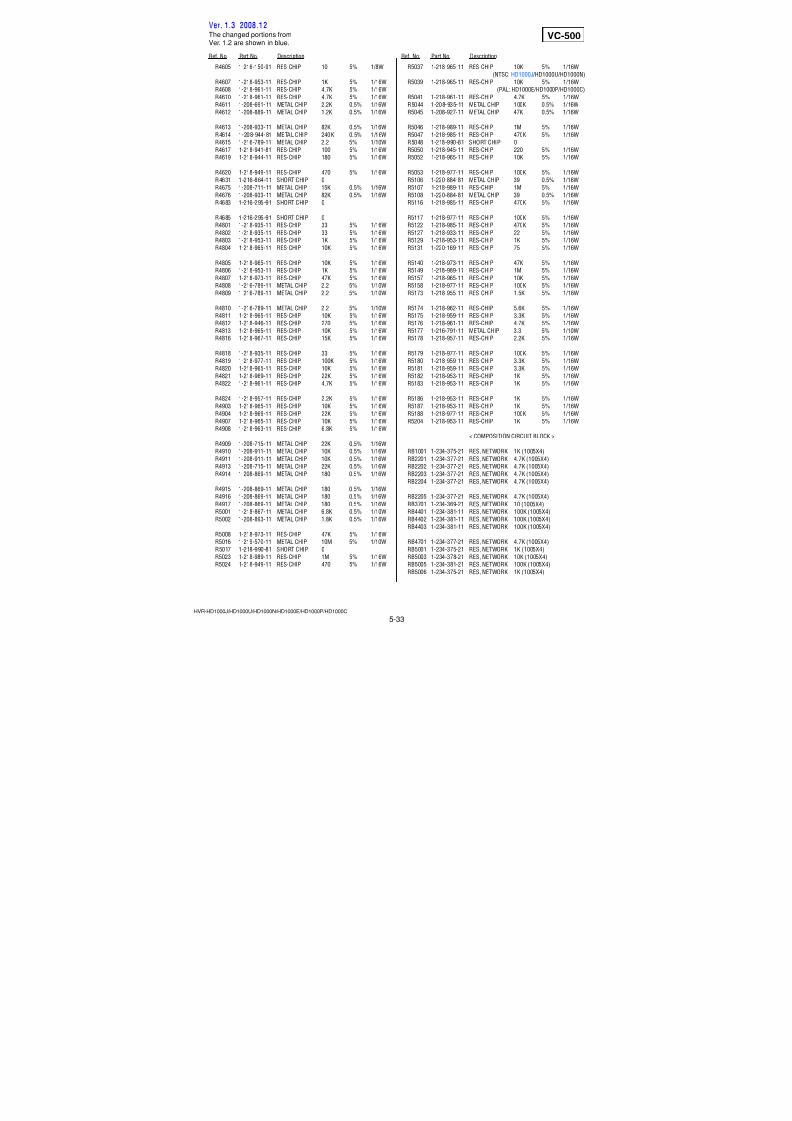
7/18/2019 SONY+HVR-HD1000 SERVICE MANUAL
http://slidepdf.com/reader/full/sonyhvr-hd1000-service-manual 128/4255-17
5. REPAIR PARTS LIST5. REPAIR PARTS LIST
HVR-HD1000J/HD1000U/HD1000N/HD1000E/HD1000P/HD1000C
Ref. No. Part No. Description Ref. No. Part No. Description
801 2-342-624-01 SPRING (PINCH LIMITTER), COIL
802 X-2024-463-2 SLIDER ASSY, MODE
803 X-2067-281-1 GEAR ASSY, CAM
804 3-075-097-11 SCREW (M1.4X1.4), SPECIAL HEAD
806 2-342-621-01 GEAR, RELAY
807 3-315-414-31 WASHER
808 2-342-620-01 GEAR, CONVERSION
809 3-084-377-01 HEAD (SCREW M1.2)
810 X-2024-460-1 BASE ASSY, CAM
811 X-2024-461-1 GEAR ASSY, MODE
812 2-342-615-01 GEAR, NO.2
813 2-342-691-01 GEAR, NO.1
814 2-637-945-01 HOLDER, MOTOR
815 3-895-822-71 SCREW (M1.2X2), SPECIAL, 0
816 2-342-689-01 SHAFT (2J), WORM
817 2-637-947-01 BASE, MOTOR HOLDER
818 1-677-049-11 FP-228 FLEXIBLE BOARD (DEW SENSOR)
819 2-342-686-01 COVER, CAPSTAN
820 2-541-984-01 MIC COVER
821 3-703-816-13 SCREW (M1.4X2.0), SPECIAL HEAD
D902 6-500-652-01 DIODE GL453SE0000F (TAPE LED)
H901 8-719-067-74 ELEMENT, HOLE HW-105A-CDE-T (S REEL)
H902 8-719-067-74 ELEMENT, HOLE HW-105A-CDE-T (T REEL)
M902 X-2067-283-2 MOTOR ASSY (LOADING)
MIC903 1-818-576-11 PIN, CONNECTOR (WITH DETECTION)
Q901 6-550-672-01 TRANSISTOR PT4850FJE00F (TAPE END)
Q902 6-550-672-01 TRANSISTOR PT4850FJE00F (TAPE TOP)
S901 1-786-448-22 SWITCH, PUSH (1 KEY) (CC DOWN)
5-1-16. LS/MECHANICAL CHASSIS BLOCK ASSEMBLY-2
ns: not supplied
801
802
803
804
804 810812
813
814
815
815
816
817
818
811
806807
808
809
ns
ns
ns
H901
D902
Q902
S901
M902
Q901
MIC903
H902
819
820
821
FP-031
(Note 1)
FP-031(Note 1)
FP-032 (Note 1, 2)
Note1: The FP-031 and FP-032 are supplied as the assembled part ofthe MD (N220) sub ass'y (S) A by attaching them with the adhesive agent.These parts are not separately supplied because assembling ofthese parts requires high accuracy.
Note2: The mode switch (S903) function works when the contactor of the FP-032contacts with the bottom surface of wiper of the mode gear ass'y.
(Note2)
Ver. 1.3 2008.12The changed portions fromVer. 1.2 are shown in blue.
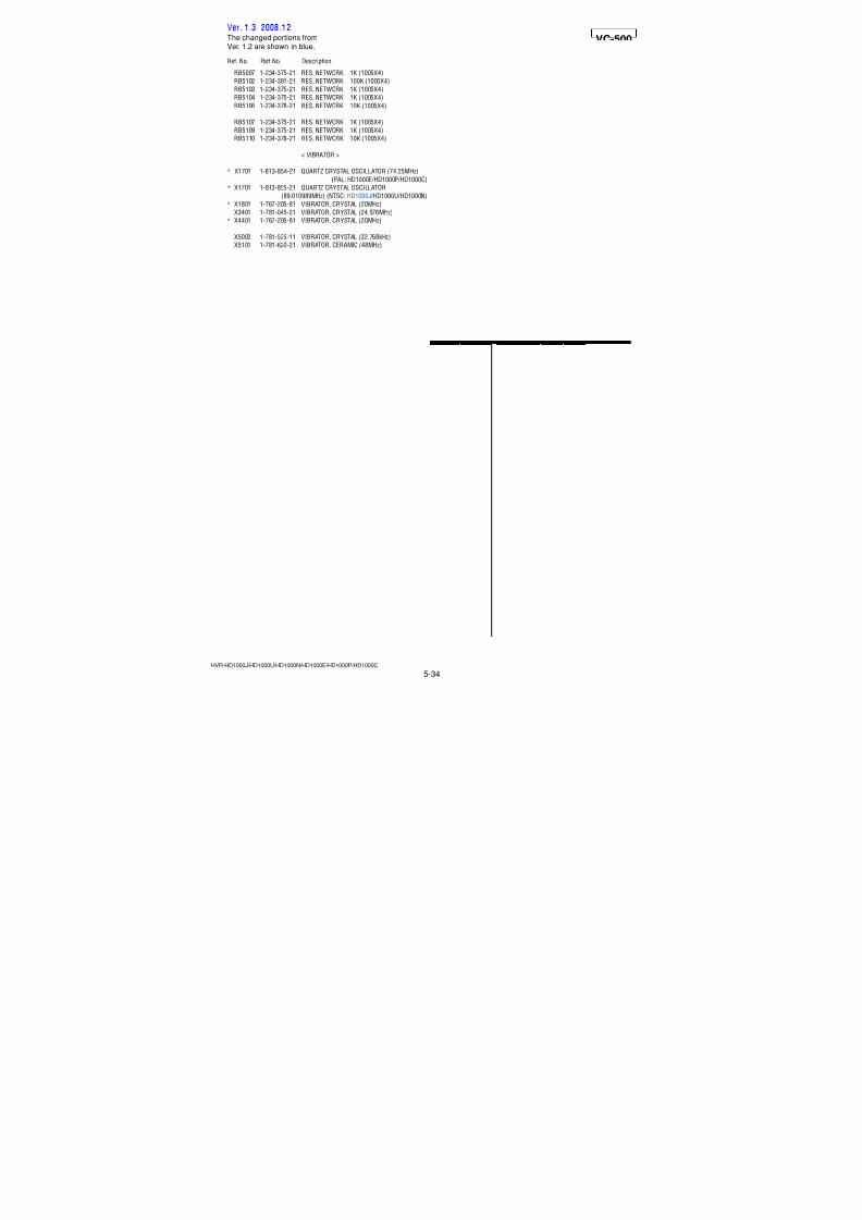
7/18/2019 SONY+HVR-HD1000 SERVICE MANUAL
http://slidepdf.com/reader/full/sonyhvr-hd1000-service-manual 129/4255-18
Ref. No. Part No. Description Ref. No. Part No. Description
5-2. ELECTRICAL PARTS LIST
HVR-HD1000J/HD1000U/HD1000N/HD1000E/HD1000P/HD1000C
• Refer to page 5-1 for mark 0.• Refer to page 5-1 for mark 0.
0 A-1438-712-A BA-008 BOARD, COMPLETE
**********************
(CN0651 is not supplied, but this is included in
BA-008 complete board.)
* 3-283-954-01 PLATE, BT RELEASE RETAINER
< CONNECTOR >
0CN0651 (Not supplied) TERMINAL BOARD, BATTERY
(BATTERY TERMINAL)
CN0652 1-794-509-11 PIN, CONNECTOR (PC BOARD) (3P)
A-1438-660-A BH-001 BOARD, COMPLETE
**********************
< CAPACITOR >
C6002 1-107-826-11 CERAMIC CHIP 0.1uF 10% 16VC6003 1-107-826-11 CERAMIC CHIP 0.1uF 10% 16V
C6004 1-107-826-11 CERAMIC CHIP 0.1uF 10% 16V
C6005 1-107-826-11 CERAMIC CHIP 0.1uF 10% 16V
C6006 1-107-826-11 CERAMIC CHIP 0.1uF 10% 16V
C6007 1-107-826-11 CERAMIC CHIP 0.1uF 10% 16V
C6008 1-107-826-11 CERAMIC CHIP 0.1uF 10% 16V
C6009 1-107-826-11 CERAMIC CHIP 0.1uF 10% 16V
C6010 1-107-826-11 CERAMIC CHIP 0.1uF 10% 16V
C6011 1-107-826-11 CERAMIC CHIP 0.1uF 10% 16V
< CONNECTOR >
CN6001 1-816-928-11 PIN, CONNECTOR 22P
* CN6002 1-779-334-51 CONNECTOR, FFC/FPC 20PCN6003 1-794-998-31 PIN, CONNECTOR 20P
CN6004 1-817-871-11 PIN, CONNECTOR 15P
CN6005 1-817-869-11 PIN, CONNECTOR 10P
CN6006 1-779-327-51 CONNECTOR, FFC/FPC 6P
CN6007 1-794-375-21 PIN, CONNECTOR 2P
< DIODE >
* D6001 6-501-956-01 DIODE MAZS068G08S0
< FERRITE BEAD >
FB6001 1-500-238-11 BEAD, FERRITE (CHIP) (1608)
FB6002 1-500-238-11 BEAD, FERRITE (CHIP) (1608)FB6003 1-500-238-11 BEAD, FERRITE (CHIP) (1608)
< TRANSISTOR >
Q6001 6-550-239-01 TRANSISTOR DTA144EMT2L
Q6002 6-550-119-01 TRANSISTOR DTC144EMT2L
< RESISTOR >
R6001 1-218-954-11 RES-CHIP 1.2K 5% 1/16W
R6003 1-218-954-11 RES-CHIP 1.2K 5% 1/16W
< SWITCH >
S6001 1-771-731-21 SWITCH, SLIDE (LCD)
A-1438-665-A BL-015 BOARD, COMPLETE
**********************
< CAPACITOR >
C5901 1-125-777-11 CERAMIC CHIP 0.1uF 10% 10V
C5902 1-165-908-11 CERAMIC CHIP 1uF 10% 10V
< CONNECTOR >
* CN5901 1-816-648-51 FFC/FPC CONNECTOR (LIF) 20P
* CN5902 1-817-560-71 CONNECTOR, FPC (ZIP) 21P
< DIODE >
* D5901 6-501-591-01 DIODE NESW007AT-T099 (EVF BACKLIGHT)
D5902 8-719-074-67 DIODE EDZ-TE61-5.6B
A-1237-309-A CM-077 BOARD, COMPLETE (SERVICE)***********************
(IC6701 (CMOS imager) is not included in CM-077
complete board. Included in CMOS block assy.)
< CAPACITOR >
C6607 1-100-415-91 CERAMIC CHIP 0.47uF 10% 6.3V
C6608 1-100-415-91 CERAMIC CHIP 0.47uF 10% 6.3V
C6609 1-100-415-91 CERAMIC CHIP 0.47uF 10% 6.3V
C6610 1-165-908-11 CERAMIC CHIP 1uF 10% 10V
C6611 1-165-908-11 CERAMIC CHIP 1uF 10% 10V
C6612 1-165-908-11 CERAMIC CHIP 1uF 10% 10V
C6613 1-165-908-11 CERAMIC CHIP 1uF 10% 10V
C6614 1-165-908-11 CERAMIC CHIP 1uF 10% 10VC6705 1-117-919-11 TANTAL. CHIP 10uF 20% 6.3V
C6706 1-117-919-11 TANTAL. CHIP 10uF 20% 6.3V
C6707 1-125-777-11 CERAMIC CHIP 0.1uF 10% 10V
C6708 1-125-889-11 CERAMIC CHIP 2.2uF 10% 10V
C6709 1-125-777-11 CERAMIC CHIP 0.1uF 10% 10V
C6717 1-117-919-11 TANTAL. CHIP 10uF 20% 6.3V
C6718 1-125-777-11 CERAMIC CHIP 0.1uF 10% 10V
C6719 1-117-919-11 TANTAL. CHIP 10uF 20% 6.3V
C6720 1-164-937-11 CERAMIC CHIP 0.001uF 10% 50V
C6724 1-117-919-11 TANTAL. CHIP 10uF 20% 6.3V
C6725 1-164-937-11 CERAMIC CHIP 0.001uF 10% 50V
C6729 1-125-777-11 CERAMIC CHIP 0.1uF 10% 10V
C6731 1-117-919-11 TANTAL. CHIP 10uF 20% 6.3V
C6732 1-117-919-11 TANTAL. CHIP 10uF 20% 6.3V
C6733 1-117-919-11 TANTAL. CHIP 10uF 20% 6.3V
C6736 1-117-919-11 TANTAL. CHIP 10uF 20% 6.3V
C6738 1-117-919-11 TANTAL. CHIP 10uF 20% 6.3V
C6739 1-117-919-11 TANTAL. CHIP 10uF 20% 6.3V
C6740 1-125-777-11 CERAMIC CHIP 0.1uF 10% 10V
C6743 1-165-908-11 CERAMIC CHIP 1uF 10% 10V
C7201 1-125-777-11 CERAMIC CHIP 0.1uF 10% 10V
C7202 1-125-777-11 CERAMIC CHIP 0.1uF 10% 10V
C7203 1-125-777-11 CERAMIC CHIP 0.1uF 10% 10V
C7204 1-125-777-11 CERAMIC CHIP 0.1uF 10% 10V
C7205 1-119-923-11 CERAMIC CHIP 0.047uF 10% 10VC7206 1-119-923-11 CERAMIC CHIP 0.047uF 10% 10V
C7207 1-119-923-11 CERAMIC CHIP 0.047uF 10% 10V
BA-008 BH-001 BL-015 CM-077
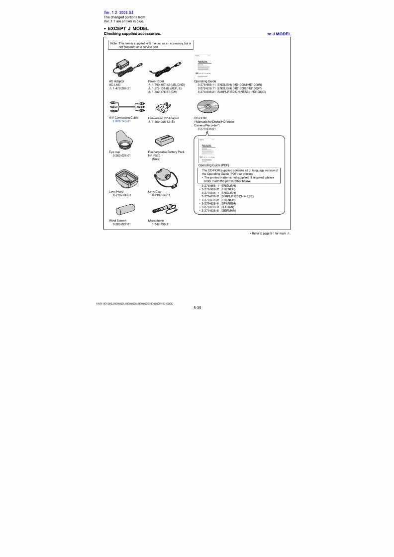
7/18/2019 SONY+HVR-HD1000 SERVICE MANUAL
http://slidepdf.com/reader/full/sonyhvr-hd1000-service-manual 130/4255-19
Ref. No. Part No. Description Ref. No. Part No. Description
HVR-HD1000J/HD1000U/HD1000N/HD1000E/HD1000P/HD1000C
C7208 1-119-923-11 CERAMIC CHIP 0.047uF 10% 10V
C7209 1-100-611-91 CERAMIC CHIP 22uF 20% 6.3V
C7210 1-100-611-91 CERAMIC CHIP 22uF 20% 6.3V
C7211 1-127-760-11 CERAMIC CHIP 4.7uF 10% 6.3V
< CONNECTOR >
CN6601 1-820-560-11 CONNECTOR, COAXIAL (RECEPTACLE) 40P
< FERRITE BEAD >
FB7201 1-400-833-21 SMD EMI FERRITE
FB7202 1-400-833-21 SMD EMI FERRITE
FB7203 1-400-833-21 SMD EMI FERRITE
FB7204 1-400-833-21 SMD EMI FERRITE
< IC >
IC6603 6-703-977-01 IC R1114Q331D-TR-FA
* IC6604 6-708-444-01 IC R1114Q281D-TR-FA
IC6605 6-703-977-01 IC R1114Q331D-TR-FAIC6606 6-703-976-01 IC R1114Q181D-TR-FA
IC7201 6-707-333-01 IC NJM3230SE7
IC6701 (Not supplied) IMX022AHF-13 (CMOS IMAGER) (Note 1)
(IC6701 is supplied including in CMOS block assy.)
< COIL >
L6702 1-216-295-91 SHORT CHIP 0 (Note 2)
L6704 1-216-295-91 SHORT CHIP 0 (Note 2)
L6705 1-216-295-91 SHORT CHIP 0 (Note 2)
L6706 1-216-295-91 SHORT CHIP 0 (Note 2)
L6707 1-216-295-91 SHORT CHIP 0 (Note 2)
L7201 1-400-588-11 INDUCTOR 10uH
< RESISTOR >
R6703 1-218-990-81 SHORT CHIP 0
R6709 1-218-929-11 RES-CHIP 10 5% 1/16W
R7201 1-218-965-11 RES-CHIP 10K 5% 1/16W
R7202 1-218-989-11 RES-CHIP 1M 5% 1/16W
R7203 1-218-989-11 RES-CHIP 1M 5% 1/16W
R7204 1-218-965-11 RES-CHIP 10K 5% 1/16W
< COMPOSITION CIRCUIT BLOCK >
RB7201 1-234-379-21 RES, NETWORK 22K (1005X4)
< SENSOR >
* SE7201 1-479-022-61 SENSOR, ANGULAR VELOCITY (32.2KHz)
(YAW)
* SE7202 1-479-022-51 SENSOR, ANGULAR VELOCITY (30.8KHz)
(PITCH)
A-1438-711-A DC-110 BOARD, COMPLETE
***********************
< CONNECTOR >
CN0601 1-774-730-21 PIN, CONNECTOR (PC BOARD) 3PCN0602 1-778-795-21 PIN, CONNECTOR (PC BOARD) 9P
0CN0610 1-817-361-11 DC-IN CONNECTOR (DC IN)
< DIODE >
* D601 6-501-573-01 DIODE CL-271TLY-C-TS (CHG)
D602 8-719-074-67 DIODE EDZ-TE61-5.6B
< RESISTOR >
R607 1-216-295-91 SHORT CHIP 0
R608 1-216-295-91 SHORT CHIP 0
A-1438-558-A EC-001 BOARD, COMPLETE
**********************
< CAPACITOR >
C5501 1-100-567-81 CERAMIC CHIP 0.01uF 10% 25V
< CONNECTOR >
CN5311 1-779-327-51 CONNECTOR, FFC/FPC 6P
< IC >
PH5501 8-749-016-83 IC GP1S092HCPIF
PH5502 8-749-016-83 IC GP1S092HCPIF
< RESISTOR >
R5501 1-218-835-11 METAL CHIP 330 0.5% 1/10W
(Not supplied) FP-031 FLEXIBLE BOARD********************
(This flexible board is included in MD (N220)
sub assy (S) A (A-1437-006-A).)
< DIODE >
D902 6-500-652-01 DIODE GL453SE0000F (TAPE LED)
< HOLE ELEMENT >
H901 8-719-067-74 ELEMENT, HOLE HW-105A-CDE-T (S REEL)
H902 8-719-067-74 ELEMENT, HOLE HW-105A-CDE-T (T REEL)
< CONNECTOR >
MIC903 1-818-576-11 PIN, CONNECTOR (WITH DETECTION)
< TRANSISTOR >
Q901 6-550-672-01 TRANSISTOR PT4850FJE00F (TAPE END)
Q902 6-550-672-01 TRANSISTOR PT4850FJE00F (TAPE TOP)
< SWITCH >
S901 1-786-448-22 SWITCH, PUSH (1 KEY) (CC DOWN)
(Not supplied) FP-032 FLEXIBLE BOARD
********************
(This flexible board with S903 is included in
(N220) sub assy (S) A (A-1437-006-A).)
CM-077 DC-110 EC-001 FP-031 FP-032
Note 1: Be sure to read “Precautions for Replacement ofImager” on page 4-3 when changing the imager.
Note 2: Short chip are mounted to the location whereL6702 and L6704 to L6707 are printed.
• Refer to page 5-1 for mark 0.
Note 1:
Ver. 1.3 2008.12
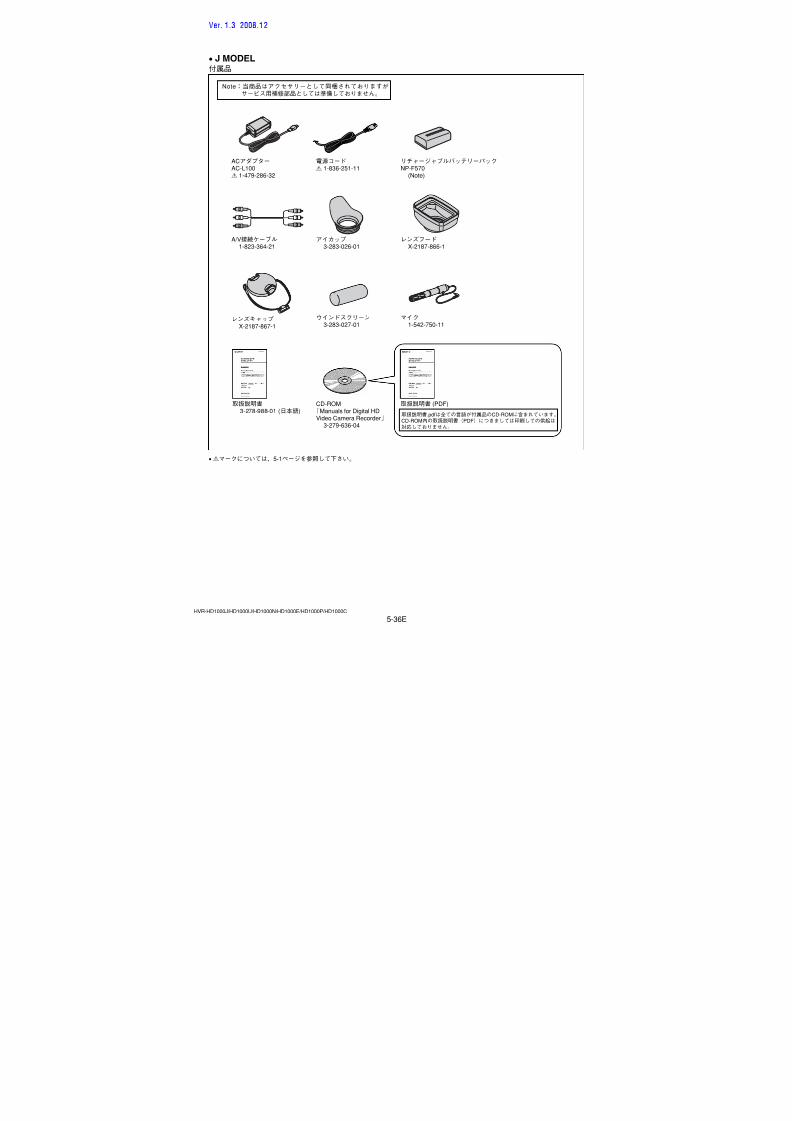
7/18/2019 SONY+HVR-HD1000 SERVICE MANUAL
http://slidepdf.com/reader/full/sonyhvr-hd1000-service-manual 131/4255-20
Ref. No. Part No. Description Ref. No. Part No. Description
HVR-HD1000J/HD1000U/HD1000N/HD1000E/HD1000P/HD1000C
1-677-049-11 FP-228 FLEXIBLE BOARD (DEW SENSOR)
********************
A-1438-659-A FP-784 FLEXIBLE BOARD, COMPLETE
******************************
< CAPACITOR >
C801 1-125-777-11 CERAMIC CHIP 0.1uF 10% 10V
< IC >
* IC801 6-600-513-01 IC TK60011CS8
A-1438-676-A FP-785 FLEXIBLE BOARD, COMPLETE
******************************
< SWITCH >
S851 1-786-180-31 SWITCH, PUSH (1KEY) (EJECT)
A-1438-675-A FP-867 FLEXIBLE BOARD, COMPLETE
******************************
< CONNECTOR >
* CN001 1-819-696-21 CONNECTOR, HDMI (HDMI) (HDMI OUT)
A-1438-658-A HI-078 BOARD, COMPLETE
**********************
< CAPACITOR >
C201 1-107-826-11 CERAMIC CHIP 0.1uF 10% 16V
< CONNECTOR >
* CN0201 1-816-654-51 FFC/FPC CONNECTOR (LIF) 6P
* CN0207 1-816-655-51 FFC/FPC CONNECTOR (LIF) 8P
< DIODE >
D201 8-719-077-09 DIODE CL-196HR-CD-T
(CAMERA RECORDING)
D202 8-719-077-09 DIODE CL-196HR-CD-T
(CAMERA RECORDING)
D203 8-719-077-09 DIODE CL-196HR-CD-T
(CAMERA RECORDING)
< TRANSISTOR >
Q201 6-550-242-01 TRANSISTOR DTC114EMT2L
Q202 6-550-119-01 TRANSISTOR DTC144EMT2L
< RESISTOR >
R201 1-218-963-11 RES-CHIP 6.8K 5% 1/16W
R202 1-218-958-11 RES-CHIP 2.7K 5% 1/16W
R204 1-218-949-81 RES-CHIP 470 5% 1/16W
R205 1-218-949-81 RES-CHIP 470 5% 1/16W
R206 1-218-949-81 RES-CHIP 470 5% 1/16W
R208 1-218-969-11 RES-CHIP 22K 5% 1/16W
A-1438-710-A HP-150 BOARD, COMPLETE
**********************
< CONNECTOR >
* CN0603 1-695-223-21 PIN, CONNECTOR (SMD) 10P* CN0604 1-580-789-22 PIN, CONNECTOR (SMD) 6P
* CN0605 1-794-276-21 CONNECTOR, SQUARE TYPE 4P (HDV/DV)
< DIODE >
D654 6-500-044-01 DIODE DF6A6.8FU (TE85R)
< FERRITE BEAD >
FB651 1-400-927-31 BEAD, FERRITE (1005)
FB652 1-400-927-31 BEAD, FERRITE (1005)
< JACK >
J651 1-818-055-21 JACK (HEADPHONES)J652 1-793-995-31 JACK, SUPER SMALL TYPE (LANC)
< RESISTOR >
R651 1-218-990-81 SHORT CHIP 0
< COMPOSITION CIRCUIT BLOCK >
RB651 1-234-400-21 CONDUCTOR, NETWORK (1005X4)
< THERMISTOR >
TH651 1-805-726-11 THERMISTOR, POSITIVE
TH652 1-805-726-11 THERMISTOR, POSITIVE
TH653 1-805-726-11 THERMISTOR, POSITIVE
TH654 1-805-726-11 THERMISTOR, POSITIVE
< VARISTOR >
VDR651 1-803-974-21 VARISTOR, CHIP (1608)
VDR652 1-803-974-21 VARISTOR, CHIP (1608)
VDR653 1-803-974-21 VARISTOR, CHIP (1608)
A-1438-674-A IF-155 BOARD, COMPLETE
**********************
< CAPACITOR >
C103 1-107-826-11 CERAMIC CHIP 0.1uF 10% 16V
C104 1-107-826-11 CERAMIC CHIP 0.1uF 10% 16V
C105 1-107-826-11 CERAMIC CHIP 0.1uF 10% 16V
C106 1-107-826-11 CERAMIC CHIP 0.1uF 10% 16V
C107 1-107-826-11 CERAMIC CHIP 0.1uF 10% 16V
C108 1-107-826-11 CERAMIC CHIP 0.1uF 10% 16V
C109 1-107-826-11 CERAMIC CHIP 0.1uF 10% 16V
C111 1-107-826-11 CERAMIC CHIP 0.1uF 10% 16V
C112 1-107-826-11 CERAMIC CHIP 0.1uF 10% 16V
C115 1-107-826-11 CERAMIC CHIP 0.1uF 10% 16V
C119 1-107-826-11 CERAMIC CHIP 0.1uF 10% 16V
C120 1-107-826-11 CERAMIC CHIP 0.1uF 10% 16V
C121 1-107-826-11 CERAMIC CHIP 0.1uF 10% 16V
FP-228 FP-784 FP-785 FP-867 HI-078 HP-150 IF-155
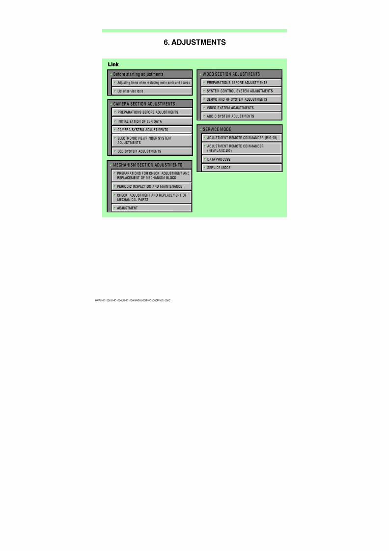
7/18/2019 SONY+HVR-HD1000 SERVICE MANUAL
http://slidepdf.com/reader/full/sonyhvr-hd1000-service-manual 132/4255-21
Ref. No. Part No. Description Ref. No. Part No. Description
HVR-HD1000J/HD1000U/HD1000N/HD1000E/HD1000P/HD1000C
< CONNECTOR >
CN0101 1-779-328-51 CONNECTOR, FFC/FPC 8P
* CN0102 1-779-334-51 CONNECTOR, FFC/FPC 20P
CN0103 1-794-998-31 PIN, CONNECTOR 20P
CN0104 1-817-871-11 PIN, CONNECTOR 15P
CN0105 1-817-869-11 PIN, CONNECTOR 10P
CN0106 1-778-506-21 PIN, CONNECTOR (PC BOARD) 2P
CN0107 1-695-320-21 PIN, CONNECTOR (1.5MM) (SMD) 2P
CN0108 1-573-290-21 PIN, CONNECTOR (1.5MM) (SMD) 4P
CN0109 1-779-330-51 CONNECTOR, FFC/FPC 12P
CN0110 1-779-331-51 CONNECTOR, FFC/FPC 14P
CN0111 1-779-327-51 CONNECTOR, FFC/FPC 6P
CN0112 1-573-806-21 PIN, CONNECTOR (1.5MM) (SMD) 6P
CN0113 1-766-383-21 PIN, CONNECTOR (1.5MM) (SMD) 12P
* CN0114 1-691-591-11 PIN, CONNECTOR (1.5MM) (SMD) 8P
CN0115 1-766-382-21 PIN, CONNECTOR (1.5MM) (SMD) 10P
CN0116 1-816-296-21 PIN, CONNECTOR (PC BOARD) 9P
CN0117 1-779-331-51 CONNECTOR, FFC/FPC 14P* CN0118 1-819-778-61 CONNECTOR, FPC (ZIF) 33P
* CN0119 1-817-544-71 CONNECTOR, FPC (ZIF) 39P
* CN0120 1-779-333-51 CONNECTOR, FFC/FPC 18P
CN0121 1-779-332-51 CONNECTOR, FFC/FPC 16P
CN0122 1-779-332-51 CONNECTOR, FFC/FPC 16P
< TRANSISTOR >
Q104 6-550-119-01 TRANSISTOR DTC144EMT2L
< RESISTOR >
R102 1-216-864-11 SHORT CHIP 0
R105 1-216-864-11 SHORT CHIP 0
R108 1-216-864-11 SHORT CHIP 0
R114 1-218-954-11 RES-CHIP 1.2K 5% 1/16W
R115 1-218-955-11 RES-CHIP 1.5K 5% 1/16W
R118 1-216-833-11 METAL CHIP 10K 5% 1/10W
R122 1-208-911-11 METAL CHIP 10K 0.5% 1/16W
A-1438-637-A JK-355 BOARD, COMPLETE
**********************
< CONNECTOR >
* CN0701 1-691-551-11 PIN, CONNECTOR (SMD) 8P
< DIODE >
D703 6-500-750-01 DIODE NSAD500H-T1-A
< JACK >
* J0703 1-821-701-11 JACK, PIN 3P (COMPONENT OUT)
A-1438-636-A JS-033 BOARD, COMPLETE
**********************
< CONNECTOR >
* CN0702 1-764-007-11 PIN, CONNECTOR (SMD) 12P
< DIODE >
* D751 6-501-956-01 DIODE MAZS068G08S0
< FERRITE BEAD >
FB751 1-400-927-31 BEAD, FERRITE (1005)FB752 1-400-927-31 BEAD, FERRITE (1005)
< JACK >
J0701 1-778-518-11 CONNECTOR, EXTERNAL (S VIDEO)
J0702 1-694-713-11 TERMINAL BOARD (A/V OUT)
< RESISTOR >
R754 1-218-953-11 RES-CHIP 1K 5% 1/16W
< SWITCH >
S0701 1-786-157-31 TACTILE SWITCH (RESET)
< VARISTOR >
VD753 1-803-974-21 VARISTOR, CHIP (1608)
A-1438-557-A LD-229 BOARD, COMPLETE
**********************
< CAPACITOR >
C5315 1-125-777-11 CERAMIC CHIP 0.1uF 10% 10V
C5316 1-119-750-11 TANTAL. CHIP 22uF 20% 6.3V
C5318 1-165-908-11 CERAMIC CHIP 1uF 10% 10V
C5405 1-137-987-81 CERAMIC CHIP 0.068uF 10% 10V
C5406 1-137-987-81 CERAMIC CHIP 0.068uF 10% 10V
C5409 1-164-939-11 CERAMIC CHIP 0.0022uF 10% 50V
C5410 1-125-777-11 CERAMIC CHIP 0.1uF 10% 10V
C5411 1-164-939-11 CERAMIC CHIP 0.0022uF 10% 50V
C5412 1-164-866-11 CERAMIC CHIP 47PF 5% 50V
C5413 1-165-908-11 CERAMIC CHIP 1uF 10% 10V
C5414 1-125-777-11 CERAMIC CHIP 0.1uF 10% 10V
C5415 1-125-777-11 CERAMIC CHIP 0.1uF 10% 10V
C5416 1-125-777-11 CERAMIC CHIP 0.1uF 10% 10V
C5417 1-125-777-11 CERAMIC CHIP 0.1uF 10% 10V
C5419 1-125-777-11 CERAMIC CHIP 0.1uF 10% 10V
C5421 1-165-897-11 TANTAL. CHIP 22uF 20% 10V
C5422 1-125-777-11 CERAMIC CHIP 0.1uF 10% 10V
C5423 1-125-777-11 CERAMIC CHIP 0.1uF 10% 10V
C5424 1-125-777-11 CERAMIC CHIP 0.1uF 10% 10V
C5425 1-125-777-11 CERAMIC CHIP 0.1uF 10% 10V
C5427 1-164-930-11 CERAMIC CHIP 330PF 5% 16V
C5428 1-119-750-11 TANTAL. CHIP 22uF 20% 6.3V
C5430 1-127-715-11 CERAMIC CHIP 0.22uF 10% 16V
C5431 1-125-777-11 CERAMIC CHIP 0.1uF 10% 10V
C5432 1-119-750-11 TANTAL. CHIP 22uF 20% 6.3V
C5433 1-164-939-11 CERAMIC CHIP 0.0022uF 10% 50V
C5434 1-164-939-11 CERAMIC CHIP 0.0022uF 10% 50V
C5705 1-165-897-11 TANTAL. CHIP 22uF 20% 10V
C5706 1-165-908-11 CERAMIC CHIP 1uF 10% 10VC5707 1-125-777-11 CERAMIC CHIP 0.1uF 10% 10V
C5708 1-165-908-11 CERAMIC CHIP 1uF 10% 10V
IF-155 JK-355 JS-033 LD-229
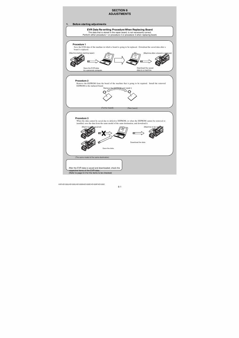
7/18/2019 SONY+HVR-HD1000 SERVICE MANUAL
http://slidepdf.com/reader/full/sonyhvr-hd1000-service-manual 133/4255-22
Ref. No. Part No. Description Ref. No. Part No. Description
HVR-HD1000J/HD1000U/HD1000N/HD1000E/HD1000P/HD1000C
C5712 1-164-937-11 CERAMIC CHIP 0.001uF 10% 50V
C5713 1-164-939-11 CERAMIC CHIP 0.0022uF 10% 50V
C5715 1-100-567-81 CERAMIC CHIP 0.01uF 10% 25V
C5716 1-164-937-11 CERAMIC CHIP 0.001uF 10% 50V
C5717 1-107-819-11 CERAMIC CHIP 0.022uF 10% 16V
C5719 1-100-567-81 CERAMIC CHIP 0.01uF 10% 25VC5722 1-127-895-91 TANTAL. CHIP 22uF 20% 4V
C5723 1-125-777-11 CERAMIC CHIP 0.1uF 10% 10V
< CONNECTOR >
* CN5301 1-817-283-71 CONNECTOR, FPC (ZIF) 51P
* CN5303 1-817-283-71 CONNECTOR, FPC (ZIF) 51P
* CN5306 1-816-654-51 FFC/FPC CONNECTOR (LIF) 6P
* CN5307 1-580-055-21 PIN, CONNECTOR (SMD) 2P
< FERRITE BEAD >
FB5401 1-500-238-11 BEAD, FERRITE (CHIP) (1608)
< IC >
* IC5304 6-708-444-01 IC R1114Q281D-TR-FA
IC5402 8-759-359-49 IC NJM3414AV (TE2)
IC5403 8-759-359-49 IC NJM3414AV (TE2)
IC5404 6-708-814-01 IC BU2343GLU-E2
* IC5703 6-709-026-01 IC R2J30500LG
< COIL >
L5301 1-400-588-11 INDUCTOR 10uH
L5401 1-469-555-21 INDUCTOR 10uH
L5701 1-400-588-11 INDUCTOR 10uH
< TRANSISTOR >
Q5301 6-550-384-01 TRANSISTOR DTC123JMT2L
< RESISTOR >
R5406 1-218-990-81 SHORT CHIP 0
R5411 1-218-965-11 RES-CHIP 10K 5% 1/16W
R5412 1-218-965-11 RES-CHIP 10K 5% 1/16W
R5413 1-218-965-11 RES-CHIP 10K 5% 1/16W
R5414 1-218-965-11 RES-CHIP 10K 5% 1/16W
R5421 1-218-965-11 RES-CHIP 10K 5% 1/16W
R5422 1-218-965-11 RES-CHIP 10K 5% 1/16W
R5423 1-218-965-11 RES-CHIP 10K 5% 1/16W
R5424 1-218-965-11 RES-CHIP 10K 5% 1/16W
R5425 1-218-965-11 RES-CHIP 10K 5% 1/16W
R5426 1-218-965-11 RES-CHIP 10K 5% 1/16W
R5427 1-218-990-81 SHORT CHIP 0
R5430 1-218-965-11 RES-CHIP 10K 5% 1/16W
R5431 1-218-965-11 RES-CHIP 10K 5% 1/16W
R5432 1-218-990-81 SHORT CHIP 0
R5433 1-208-909-11 METAL CHIP 8.2K 0.5% 1/16W
R5434 1-208-721-11 METAL CHIP 39K 0.5% 1/16W
R5435 1-218-958-11 RES-CHIP 2.7K 5% 1/16W
R5436 1-218-958-11 RES-CHIP 2.7K 5% 1/16W
R5437 1-208-909-11 METAL CHIP 8.2K 0.5% 1/16W
R5438 1-208-721-11 METAL CHIP 39K 0.5% 1/16WR5439 1-208-703-11 METAL CHIP 6.8K 0.5% 1/16W
R5440 1-208-941-11 METAL CHIP 180K 0.5% 1/16W
R5441 1-208-671-11 METAL CHIP 330 0.5% 1/16W
R5442 1-218-953-11 RES-CHIP 1K 5% 1/16W
R5443 1-208-943-11 METAL CHIP 220K 0.5% 1/16W
R5444 1-208-911-11 METAL CHIP 10K 0.5% 1/16W
R5445 1-208-909-11 METAL CHIP 8.2K 0.5% 1/16W
R5446 1-208-909-11 METAL CHIP 8.2K 0.5% 1/16W
R5447 1-218-990-81 SHORT CHIP 0
R5448 1-218-990-81 SHORT CHIP 0
R5449 1-208-911-11 METAL CHIP 10K 0.5% 1/16W
R5450 1-208-943-11 METAL CHIP 220K 0.5% 1/16W
R5451 1-218-937-11 RES-CHIP 47 5% 1/16W
R5452 1-218-965-11 RES-CHIP 10K 5% 1/16W
R5453 1-218-990-81 SHORT CHIP 0
R5454 1-208-941-11 METAL CHIP 180K 0.5% 1/16W
R5455 1-208-703-11 METAL CHIP 6.8K 0.5% 1/16W
R5456 1-208-909-11 METAL CHIP 8.2K 0.5% 1/16W
R5457 1-208-909-11 METAL CHIP 8.2K 0.5% 1/16W
R5458 1-218-953-11 RES-CHIP 1K 5% 1/16W
R5459 1-208-721-11 METAL CHIP 39K 0.5% 1/16WR5460 1-208-721-11 METAL CHIP 39K 0.5% 1/16W
R5461 1-218-958-11 RES-CHIP 2.7K 5% 1/16W
R5462 1-218-958-11 RES-CHIP 2.7K 5% 1/16W
R5720 1-208-719-11 METAL CHIP 33K 0.5% 1/16W
R5721 1-208-721-11 METAL CHIP 39K 0.5% 1/16W
R5725 1-218-978-11 RES-CHIP 120K 5% 1/16W
R5726 1-208-689-11 METAL CHIP 1.8K 0.5% 1/16W
R5729 1-208-705-11 METAL CHIP 8.2K 0.5% 1/16W
R5733 1-208-707-11 METAL CHIP 10K 0.5% 1/16W
R5736 1-208-721-11 METAL CHIP 39K 0.5% 1/16W
R5737 1-208-721-11 METAL CHIP 39K 0.5% 1/16W
R5741 1-218-978-11 RES-CHIP 120K 5% 1/16W
R5742 1-208-689-11 METAL CHIP 1.8K 0.5% 1/16W
R5745 1-208-705-11 METAL CHIP 8.2K 0.5% 1/16W
R5749 1-208-707-11 METAL CHIP 10K 0.5% 1/16W
R5770 1-218-977-11 RES-CHIP 100K 5% 1/16W
R5771 1-218-977-11 RES-CHIP 100K 5% 1/16W
R5772 1-218-977-11 RES-CHIP 100K 5% 1/16W
R5773 1-218-977-11 RES-CHIP 100K 5% 1/16W
R5774 1-218-977-11 RES-CHIP 100K 5% 1/16W
R5776 1-218-977-11 RES-CHIP 100K 5% 1/16W
R5787 1-218-990-81 SHORT CHIP 0
R5788 1-218-990-81 SHORT CHIP 0
R5791 1-218-990-81 SHORT CHIP 0
R5792 1-218-990-81 SHORT CHIP 0
R5793 1-218-941-81 RES-CHIP 100 5% 1/16W
A-1438-670-A MC-188 BOARD, COMPLETE
***********************
< CAPACITOR >
C401 1-162-962-11 CERAMIC CHIP 470PF 10% 50V
< CONNECTOR >
CN0401 1-580-057-11 PIN, CONNECTOR (SMD) 4P
< JACK >
J401 1-793-703-21 JACK (DIA. 3.5) (MIC (PLUG IN POWER))
LD-229 MC-188
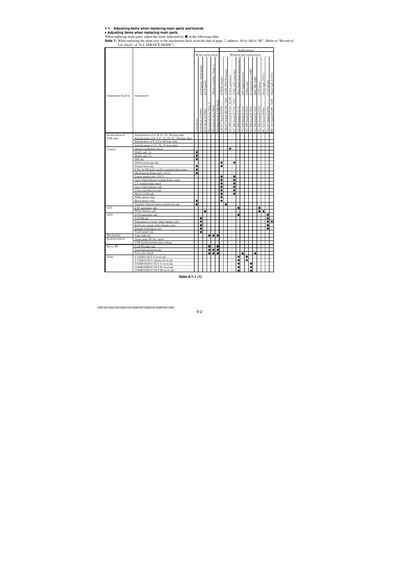
7/18/2019 SONY+HVR-HD1000 SERVICE MANUAL
http://slidepdf.com/reader/full/sonyhvr-hd1000-service-manual 134/4255-23
Ref. No. Part No. Description Ref. No. Part No. Description
HVR-HD1000J/HD1000U/HD1000N/HD1000E/HD1000P/HD1000C
< RESISTOR >
R401 1-218-990-81 SHORT CHIP 0
< VARISTOR >
* VDR401 1-802-279-11 VARISTOR (SMD)
* VDR402 1-802-279-11 VARISTOR (SMD)
A-1438-628-A MO-027 BOARD, COMPLETE
***********************
< CONNECTOR >
* CN0504 1-817-555-51 CONNECTOR, FFC/FPC 8P
CN0505 1-778-506-21 PIN, CONNECTOR (PC BOARD) 2P
< DIODE >
D551 6-500-252-01 DIODE SML-512WWT86 (TAPE)D552 6-500-252-01 DIODE SML-512WWT86 (MEMORY)
D558 6-500-594-01 DIODE CL-196SYG-CD-T (PLAY/EDIT)
D559 6-500-594-01 DIODE CL-196SYG-CD-T (PLAY/EDIT)
< RESISTOR >
R551 1-218-937-11 RES-CHIP 47 5% 1/16W
R552 1-218-937-11 RES-CHIP 47 5% 1/16W
R553 1-218-937-11 RES-CHIP 47 5% 1/16W
< VARISTOR >
* VDR551 1-802-279-11 VARISTOR (SMD)
* VDR552 1-802-279-11 VARISTOR (SMD)
A-1438-635-A MS-379 BOARD, COMPLETE
**********************
(BT901 is not included in MS-379 complete board.)
< BATTERY HOLDER >
0BH8001 1-756-615-41 HOLDER, BATTERY (Note)
< BATTERY >
0BT901 1-756-134-12 BATTERY, STORAGE, LITHIUM (Note)
< CONNECTOR >
* CN8001 1-818-087-51 CONNECTOR, FFC/FPC (LIF) 26P
CN8002 1-778-506-21 PIN, CONNECTOR (PC BOARD) 2P
CN8003 1-779-328-51 CONNECTOR, FFC/FPC 8P
CN8004 1-817-913-41 MEMORY STICK DUO CONNECTOR
< DIODE >
D8003 6-501-216-01 DIODE CL-271HR-C-TS (MS ACCESS)
< RESISTOR >
R8001 1-218-947-11 RES-CHIP 330 5% 1/16W
R8002 1-218-990-81 SHORT CHIP 0
R8003 1-218-990-81 SHORT CHIP 0R8004 1-218-990-81 SHORT CHIP 0
R8005 1-218-990-81 SHORT CHIP 0
R8006 1-218-990-81 SHORT CHIP 0
R8007 1-218-990-81 SHORT CHIP 0
R8008 1-218-990-81 SHORT CHIP 0
A-1438-618-A NS-022 BOARD, COMPLETE
***********************
< CAPACITOR >
C901 1-165-989-11 CERAMIC CHIP 10uF 10% 6.3V
< CONNECTOR >
CN0901 1-779-330-51 CONNECTOR, FFC/FPC 12P
CN0902 1-779-327-51 CONNECTOR, FFC/FPC 6P
CN0903 1-779-327-51 CONNECTOR, FFC/FPC 6P
< DIODE >
* D901 6-501-598-01 DIODE CL-335IRS-X-TS (NIGHTSHOT)
< RESISTOR >
R901 1-216-801-11 METAL CHIP 22 5% 1/10W
R902 1-216-801-11 METAL CHIP 22 5% 1/10W
A-1438-668-A PD-342 BOARD, COMPLETE
**********************
< CAPACITOR >
C6201 1-100-581-81 CERAMIC CHIP 0.0047uF 10% 50V
C6202 1-100-581-81 CERAMIC CHIP 0.0047uF 10% 50V
C6203 1-165-989-11 CERAMIC CHIP 10uF 10% 6.3V
C6204 1-127-895-91 TANTAL. CHIP 22uF 20% 4V
C6205 1-165-884-11 CERAMIC CHIP 2.2uF 10% 6.3V
C6206 1-125-777-11 CERAMIC CHIP 0.1uF 10% 10V
C6208 1-100-567-81 CERAMIC CHIP 0.01uF 10% 25V
C6209 1-100-567-81 CERAMIC CHIP 0.01uF 10% 25V
C6210 1-100-567-81 CERAMIC CHIP 0.01uF 10% 25V
C6211 1-125-777-11 CERAMIC CHIP 0.1uF 10% 10V
C6212 1-125-777-11 CERAMIC CHIP 0.1uF 10% 10V
C6213 1-100-786-91 TANTAL. CHIP 22uF 20% 6.3V
C6214 1-165-908-11 CERAMIC CHIP 1uF 10% 10V
C6215 1-165-908-11 CERAMIC CHIP 1uF 10% 10V
C6216 1-165-989-11 CERAMIC CHIP 10uF 10% 6.3V
C6217 1-165-908-11 CERAMIC CHIP 1uF 10% 10V
C6218 1-125-777-11 CERAMIC CHIP 0.1uF 10% 10V
C6219 1-164-739-11 CERAMIC CHIP 560PF 5% 50V
C6220 1-165-884-11 CERAMIC CHIP 2.2uF 10% 6.3V
C6221 1-165-908-11 CERAMIC CHIP 1uF 10% 10V
C6225 1-100-567-81 CERAMIC CHIP 0.01uF 10% 25V
C6226 1-100-567-81 CERAMIC CHIP 0.01uF 10% 25V
C6227 1-125-777-11 CERAMIC CHIP 0.1uF 10% 10V
C6228 1-125-777-11 CERAMIC CHIP 0.1uF 10% 10V
• Refer to page 5-1 for mark 0.
MC-188 MO-027 MS-379 NS-022 PD-342
CAUTIONDanger of explosion if battery is incorrectly replaced.Replace only with the same or equivalent type.
Note: Replace the battery holder (BH8001) together whenreplacing the lithium battery (BT901) on the MS-379board. (The battery holder removed once cannot beused again.)When mounting these parts, mount new battery holderfirst and attach new lithium battery next.
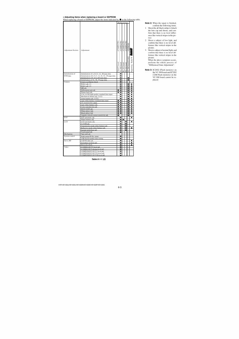
7/18/2019 SONY+HVR-HD1000 SERVICE MANUAL
http://slidepdf.com/reader/full/sonyhvr-hd1000-service-manual 135/4255-24
Ref. No. Part No. Description Ref. No. Part No. Description
HVR-HD1000J/HD1000U/HD1000N/HD1000E/HD1000P/HD1000C
< CONNECTOR >
CN6201 1-794-322-51 FFC/CONNECTOR, FPC (ZIF) 6P
CN6202 1-816-928-11 PIN, CONNECTOR 22P
* CN6205 1-819-913-71 CONNECTOR, FPC (ZIF) 24P
< DIODE >
D6204 8-719-071-34 DIODE RB521S-30-TE61
D6205 8-719-071-34 DIODE RB521S-30-TE61
* D6206 6-501-597-01 DIODE NSSW008DT-T108 (BACKLIGHT)
* D6207 6-501-597-01 DIODE NSSW008DT-T108 (BACKLIGHT)
* D6208 6-501-597-01 DIODE NSSW008DT-T108 (BACKLIGHT)
< FERRITE BEAD >
FB6201 1-400-331-11 FERRITE, EMI (SMD) (1005)
< IC >
* IC6201 6-710-240-01 IC IR3Y65M4
IC6202 8-759-693-13 IC NJM12904V (TE2)
< COIL >
L6201 1-400-588-11 INDUCTOR 10uH
L6202 1-400-588-11 INDUCTOR 10uH
L6203 1-400-588-11 INDUCTOR 10uH
< TRANSISTOR >
Q6201 8-729-427-37 TRANSISTOR XP411F-TXE
Q6202 8-729-427-67 TRANSISTOR XP421F-TXE
Q6203 8-729-053-52 TRANSISTOR RN1910FE (TPLR3)
Q6204 8-729-425-50 TRANSISTOR 2SB1462-Q
Q6205 8-729-425-50 TRANSISTOR 2SB1462-Q
Q6206 8-729-425-50 TRANSISTOR 2SB1462-Q
Q6207 6-550-150-01 TRANSISTOR SSM3J09FU (TE85L)
Q6208 6-550-119-01 TRANSISTOR DTC144EMT2L
Q6210 8-729-053-84 TRANSISTOR SSM3KO9FU (T5LSONY1)
Q6211 6-551-184-01 TRANSISTOR MCH6305-TL-E-S
Q6212 6-551-184-01 TRANSISTOR MCH6305-TL-E-S
< RESISTOR >
R6206 1-218-990-81 SHORT CHIP 0
R6208 1-218-949-11 RES-CHIP 470 5% 1/16W
R6211 1-218-936-11 RES-CHIP 39 5% 1/16W
R6212 1-218-965-11 RES-CHIP 10K 5% 1/16W
R6213 1-208-922-11 METAL CHIP 30K 0.5% 1/16W
R6214 1-208-943-11 METAL CHIP 220K 0.5% 1/16W
R6215 1-218-975-11 RES-CHIP 68K 5% 1/16W
R6216 1-218-973-11 RES-CHIP 47K 5% 1/16W
R6217 1-218-973-11 RES-CHIP 47K 5% 1/16W
R6218 1-218-953-11 RES-CHIP 1K 5% 1/16W
R6219 1-208-935-11 METAL CHIP 100K 0.5% 1/16W
R6220 1-208-911-11 METAL CHIP 10K 0.5% 1/16W
R6221 1-218-961-11 RES-CHIP 4.7K 5% 1/16W
R6222 1-218-957-11 RES-CHIP 2.2K 5% 1/16W
R6227 1-220-876-81 METAL CHIP 18 0.5% 1/16W
R6231 1-220-876-81 METAL CHIP 18 0.5% 1/16WR6232 1-220-876-81 METAL CHIP 18 0.5% 1/16W
R6235 1-218-977-11 RES-CHIP 100K 5% 1/16W
R6236 1-218-977-11 RES-CHIP 100K 5% 1/16W
R6237 1-218-977-11 RES-CHIP 100K 5% 1/16W
R6241 1-218-981-91 RES-CHIP 220K 5% 1/16W
R6249 1-218-990-81 SHORT CHIP 0
R6250 1-218-990-81 SHORT CHIP 0
R6251 1-218-990-81 SHORT CHIP 0
R6252 1-218-990-81 SHORT CHIP 0
R6253 1-218-990-81 SHORT CHIP 0
R6254 1-218-990-81 SHORT CHIP 0
A-1438-667-A RE-038 BOARD, COMPLETE
**********************
< CONNECTOR >
CN0851 1-794-375-21 PIN, CONNECTOR 2P
< SWITCH >
S0851 1-786-179-11 SWITCH, PUSH (1KEY) (PANEL REVERSE)
A-1438-625-A SP-048 BOARD, COMPLETE
**********************
< CONNECTOR >
CN0501 1-779-331-51 CONNECTOR, FFC/FPC 14P
CN0502 1-779-328-51 CONNECTOR, FFC/FPC 8P
< DIODE >
D501 8-719-084-17 DIODE EMZ6.8ET2R
< RESISTOR >
R502 1-218-990-81 SHORT CHIP 0
< SWITCH >
S0501 1-786-157-31 TACTILE SWITCH (DISPLAY/BATT INFO)
S0502 1-771-731-21 SWITCH, SLIDE (NIGHTSHOT)
S0503 1-786-157-31 TACTILE SWITCH (BACK LIGHT)
S0504 1-786-157-31 TACTILE SWITCH (MANUAL)
A-1438-634-A US-014 BOARD, COMPLETE
***********************
< CONNECTOR >
* CN8101 1-816-655-51 FFC/FPC CONNECTOR (LIF) 8P
* CN8102 1-816-655-51 FFC/FPC CONNECTOR (LIF) 8P
CN8103 1-784-010-11 CONNECTOR, USB (B) (USB)
< DIODE >
D8101 8-719-078-02 DIODE 1SS357 (T3SONY1)
D8102 6-500-776-01 DIODE MAZW068H0LS0
< RESISTOR >
R8101 1-218-965-11 RES-CHIP 10K 5% 1/16W
R8102 1-218-965-11 RES-CHIP 10K 5% 1/16WR8103 1-218-990-81 SHORT CHIP 0
R8104 1-218-990-81 SHORT CHIP 0
PD-342 RE-038 SP-048 US-014
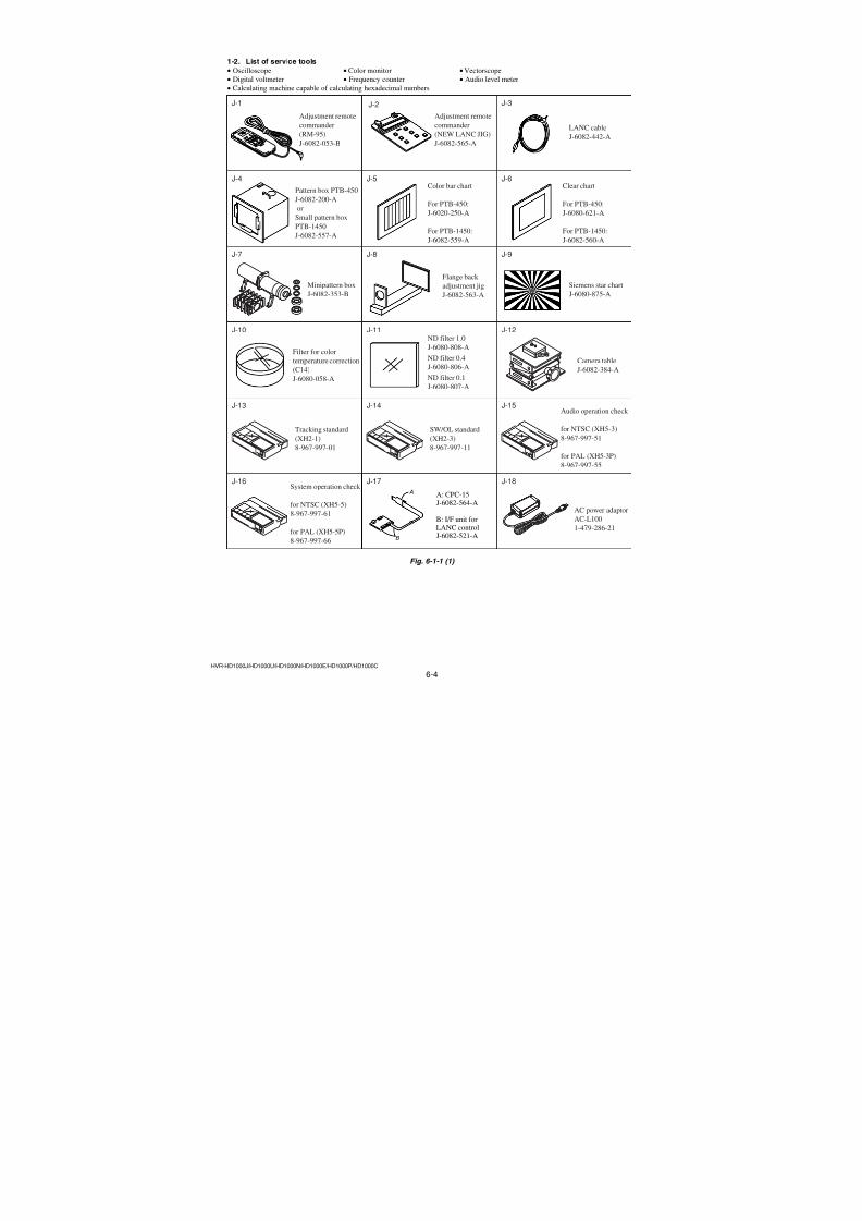
7/18/2019 SONY+HVR-HD1000 SERVICE MANUAL
http://slidepdf.com/reader/full/sonyhvr-hd1000-service-manual 136/4255-25
Ref. No. Part No. Description Ref. No. Part No. Description
HVR-HD1000J/HD1000U/HD1000N/HD1000E/HD1000P/HD1000C
A-1438-762-A VC-500 BOARD, COMPLETE
(NTSC: HD1000U/HD1000N)
A-1438-763-A VC-500 BOARD, COMPLETE
(PAL: HD1000E/HD1000P/HD1000C)
A-1671-373-A VC-500 BOARD, COMPLETE (NTSC: HD1000J)
**********************
(IC2402 and IC5202 are not supplied, but theyare included in VC-500 complete board.)
< CAPACITOR >
C1004 1-127-895-91 TANTAL. CHIP 22uF 20% 4V
C1009 1-125-777-11 CERAMIC CHIP 0.1uF 10% 10V
C1010 1-125-777-11 CERAMIC CHIP 0.1uF 10% 10V
C1011 1-125-777-11 CERAMIC CHIP 0.1uF 10% 10V
C1012 1-112-717-91 CERAMIC CHIP 1uF 10% 6.3V
C1205 1-125-777-11 CERAMIC CHIP 0.1uF 10% 10V
C1206 1-125-777-11 CERAMIC CHIP 0.1uF 10% 10V
C1207 1-125-777-11 CERAMIC CHIP 0.1uF 10% 10V
C1208 1-125-777-11 CERAMIC CHIP 0.1uF 10% 10V
C1209 1-125-777-11 CERAMIC CHIP 0.1uF 10% 10V
C1210 1-125-777-11 CERAMIC CHIP 0.1uF 10% 10V
C1213 1-125-777-11 CERAMIC CHIP 0.1uF 10% 10V
C1214 1-125-777-11 CERAMIC CHIP 0.1uF 10% 10V
C1215 1-125-777-11 CERAMIC CHIP 0.1uF 10% 10V
C1216 1-125-777-11 CERAMIC CHIP 0.1uF 10% 10V
C1217 1-125-777-11 CERAMIC CHIP 0.1uF 10% 10V
C1218 1-125-777-11 CERAMIC CHIP 0.1uF 10% 10V
C1219 1-125-777-11 CERAMIC CHIP 0.1uF 10% 10V
C1220 1-125-777-11 CERAMIC CHIP 0.1uF 10% 10V
C1221 1-125-777-11 CERAMIC CHIP 0.1uF 10% 10V
C1222 1-125-777-11 CERAMIC CHIP 0.1uF 10% 10V
C1223 1-117-919-11 TANTAL. CHIP 10uF 20% 6.3V
C1224 1-125-777-11 CERAMIC CHIP 0.1uF 10% 10V
C1225 1-117-919-11 TANTAL. CHIP 10uF 20% 6.3V
C1305 1-125-777-11 CERAMIC CHIP 0.1uF 10% 10V
C1306 1-125-777-11 CERAMIC CHIP 0.1uF 10% 10V
C1307 1-125-777-11 CERAMIC CHIP 0.1uF 10% 10V
C1308 1-125-777-11 CERAMIC CHIP 0.1uF 10% 10V
C1309 1-125-777-11 CERAMIC CHIP 0.1uF 10% 10V
C1310 1-125-777-11 CERAMIC CHIP 0.1uF 10% 10V
C1313 1-125-777-11 CERAMIC CHIP 0.1uF 10% 10V
C1314 1-125-777-11 CERAMIC CHIP 0.1uF 10% 10V
C1315 1-125-777-11 CERAMIC CHIP 0.1uF 10% 10V
C1316 1-125-777-11 CERAMIC CHIP 0.1uF 10% 10V
C1317 1-125-777-11 CERAMIC CHIP 0.1uF 10% 10V
C1318 1-125-777-11 CERAMIC CHIP 0.1uF 10% 10V
C1319 1-125-777-11 CERAMIC CHIP 0.1uF 10% 10V
C1320 1-125-777-11 CERAMIC CHIP 0.1uF 10% 10V
C1321 1-125-777-11 CERAMIC CHIP 0.1uF 10% 10V
C1322 1-125-777-11 CERAMIC CHIP 0.1uF 10% 10V
C1323 1-125-777-11 CERAMIC CHIP 0.1uF 10% 10V
C1324 1-117-919-11 TANTAL. CHIP 10uF 20% 6.3V
C1325 1-117-919-11 TANTAL. CHIP 10uF 20% 6.3V
C1702 1-125-777-11 CERAMIC CHIP 0.1uF 10% 10V
C1703 1-117-919-11 TANTAL. CHIP 10uF 20% 6.3V
C1704 1-125-777-11 CERAMIC CHIP 0.1uF 10% 10VC1705 1-125-777-11 CERAMIC CHIP 0.1uF 10% 10V
C1706 1-125-777-11 CERAMIC CHIP 0.1uF 10% 10V
C1707 1-125-777-11 CERAMIC CHIP 0.1uF 10% 10V
C1708 1-125-777-11 CERAMIC CHIP 0.1uF 10% 10V
C1709 1-125-777-11 CERAMIC CHIP 0.1uF 10% 10V
C1710 1-125-777-11 CERAMIC CHIP 0.1uF 10% 10V
C1711 1-125-777-11 CERAMIC CHIP 0.1uF 10% 10V
C1712 1-125-777-11 CERAMIC CHIP 0.1uF 10% 10V
C1713 1-125-777-11 CERAMIC CHIP 0.1uF 10% 10V
C1714 1-125-777-11 CERAMIC CHIP 0.1uF 10% 10V
C1715 1-125-777-11 CERAMIC CHIP 0.1uF 10% 10V
C1716 1-125-777-11 CERAMIC CHIP 0.1uF 10% 10V
C1717 1-125-777-11 CERAMIC CHIP 0.1uF 10% 10V
C1718 1-125-777-11 CERAMIC CHIP 0.1uF 10% 10V
C1719 1-100-786-91 TANTAL. CHIP 22uF 20% 6.3V
C1720 1-165-989-11 CERAMIC CHIP 10uF 10% 6.3V
C1721 1-100-786-91 TANTAL. CHIP 22uF 20% 6.3V
C1722 1-165-989-11 CERAMIC CHIP 10uF 10% 6.3V
C1723 1-125-777-11 CERAMIC CHIP 0.1uF 10% 10V
C1724 1-165-989-11 CERAMIC CHIP 10uF 10% 6.3V
C1725 1-125-777-11 CERAMIC CHIP 0.1uF 10% 10VC1726 1-100-786-91 TANTAL. CHIP 22uF 20% 6.3V
C1727 1-125-777-11 CERAMIC CHIP 0.1uF 10% 10V
C1728 1-125-777-11 CERAMIC CHIP 0.1uF 10% 10V
C1729 1-117-919-11 TANTAL. CHIP 10uF 20% 6.3V
C1730 1-165-989-11 CERAMIC CHIP 10uF 10% 6.3V
C1731 1-127-895-91 TANTAL. CHIP 22uF 20% 4V
C1732 1-127-895-91 TANTAL. CHIP 22uF 20% 4V
C1733 1-100-786-91 TANTAL. CHIP 22uF 20% 6.3V
C1801 1-100-567-81 CERAMIC CHIP 0.01uF 10% 25V
C1802 1-100-567-81 CERAMIC CHIP 0.01uF 10% 25V
C1804 1-164-850-11 CERAMIC CHIP 10PF 0.5PF 50V
C1805 1-164-850-11 CERAMIC CHIP 10PF 0.5PF 50V
C1806 1-125-777-11 CERAMIC CHIP 0.1uF 10% 10V
C1807 1-125-777-11 CERAMIC CHIP 0.1uF 10% 10V
C1808 1-125-777-11 CERAMIC CHIP 0.1uF 10% 10V
C1809 1-125-777-11 CERAMIC CHIP 0.1uF 10% 10V
C1810 1-125-777-11 CERAMIC CHIP 0.1uF 10% 10V
C1811 1-125-777-11 CERAMIC CHIP 0.1uF 10% 10V
C1812 1-165-908-11 CERAMIC CHIP 1uF 10% 10V
C1813 1-165-908-11 CERAMIC CHIP 1uF 10% 10V
C1817 1-100-567-81 CERAMIC CHIP 0.01uF 10% 25V
C1902 1-125-777-11 CERAMIC CHIP 0.1uF 10% 10V
C1903 1-125-777-11 CERAMIC CHIP 0.1uF 10% 10V
C1904 1-125-777-11 CERAMIC CHIP 0.1uF 10% 10V
C1905 1-125-777-11 CERAMIC CHIP 0.1uF 10% 10V
C1906 1-165-989-11 CERAMIC CHIP 10uF 10% 6.3V
C2003 1-165-884-11 CERAMIC CHIP 2.2uF 10% 6.3V
C2004 1-165-884-11 CERAMIC CHIP 2.2uF 10% 6.3V
C2005 1-165-884-11 CERAMIC CHIP 2.2uF 10% 6.3V
C2010 1-165-989-11 CERAMIC CHIP 10uF 10% 6.3V
C2011 1-165-908-11 CERAMIC CHIP 1uF 10% 10V
C2012 1-165-908-11 CERAMIC CHIP 1uF 10% 10V
C2013 1-165-908-11 CERAMIC CHIP 1uF 10% 10V
C2014 1-127-895-91 TANTAL. CHIP 22uF 20% 4V
C2015 1-127-895-91 TANTAL. CHIP 22uF 20% 4V
C2016 1-165-908-11 CERAMIC CHIP 1uF 10% 10V
C2017 1-165-989-11 CERAMIC CHIP 10uF 10% 6.3VC2101 1-165-989-11 CERAMIC CHIP 10uF 10% 6.3V
C2102 1-127-895-91 TANTAL. CHIP 22uF 20% 4V
VC-500Ver. 1.3 2008.12The changed portions fromVer. 1.2 are shown in blue.
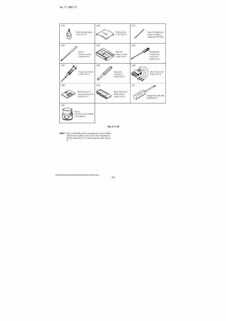
7/18/2019 SONY+HVR-HD1000 SERVICE MANUAL
http://slidepdf.com/reader/full/sonyhvr-hd1000-service-manual 137/4255-26
Ref. No. Part No. Description Ref. No. Part No. Description
HVR-HD1000J/HD1000U/HD1000N/HD1000E/HD1000P/HD1000C
C2103 1-165-989-11 CERAMIC CHIP 10uF 10% 6.3V
C2104 1-165-989-11 CERAMIC CHIP 10uF 10% 6.3V
C2105 1-165-989-11 CERAMIC CHIP 10uF 10% 6.3V
C2106 1-100-611-91 CERAMIC CHIP 22uF 20% 6.3V
C2107 1-125-777-11 CERAMIC CHIP 0.1uF 10% 10V
C2108 1-125-777-11 CERAMIC CHIP 0.1uF 10% 10VC2109 1-125-777-11 CERAMIC CHIP 0.1uF 10% 10V
C2110 1-125-777-11 CERAMIC CHIP 0.1uF 10% 10V
C2111 1-125-777-11 CERAMIC CHIP 0.1uF 10% 10V
C2112 1-125-777-11 CERAMIC CHIP 0.1uF 10% 10V
C2113 1-125-777-11 CERAMIC CHIP 0.1uF 10% 10V
C2114 1-125-777-11 CERAMIC CHIP 0.1uF 10% 10V
C2115 1-125-777-11 CERAMIC CHIP 0.1uF 10% 10V
C2116 1-125-777-11 CERAMIC CHIP 0.1uF 10% 10V
C2117 1-125-777-11 CERAMIC CHIP 0.1uF 10% 10V
C2118 1-125-777-11 CERAMIC CHIP 0.1uF 10% 10V
C2119 1-125-777-11 CERAMIC CHIP 0.1uF 10% 10V
C2120 1-125-777-11 CERAMIC CHIP 0.1uF 10% 10V
C2121 1-125-777-11 CERAMIC CHIP 0.1uF 10% 10V
C2122 1-100-611-91 CERAMIC CHIP 22uF 20% 6.3V
C2123 1-100-611-91 CERAMIC CHIP 22uF 20% 6.3V
C2124 1-125-777-11 CERAMIC CHIP 0.1uF 10% 10V
C2125 1-125-777-11 CERAMIC CHIP 0.1uF 10% 10V
C2126 1-100-505-11 CERAMIC CHIP 0.1uF 20% 16V
C2127 1-125-777-11 CERAMIC CHIP 0.1uF 10% 10V
C2128 1-100-611-91 CERAMIC CHIP 22uF 20% 6.3V
C2129 1-125-777-11 CERAMIC CHIP 0.1uF 10% 10V
C2130 1-125-777-11 CERAMIC CHIP 0.1uF 10% 10V
C2131 1-125-777-11 CERAMIC CHIP 0.1uF 10% 10V
C2132 1-100-505-11 CERAMIC CHIP 0.1uF 20% 16V
C2134 1-125-777-11 CERAMIC CHIP 0.1uF 10% 10V
C2135 1-125-777-11 CERAMIC CHIP 0.1uF 10% 10V
C2136 1-100-505-11 CERAMIC CHIP 0.1uF 20% 16V
C2137 1-125-777-11 CERAMIC CHIP 0.1uF 10% 10V
C2138 1-125-777-11 CERAMIC CHIP 0.1uF 10% 10V
C2139 1-127-895-91 TANTAL. CHIP 22uF 20% 4V
C2140 1-125-777-11 CERAMIC CHIP 0.1uF 10% 10V
C2141 1-125-777-11 CERAMIC CHIP 0.1uF 10% 10V
C2142 1-127-895-91 TANTAL. CHIP 22uF 20% 4V
C2201 1-127-760-11 CERAMIC CHIP 4.7uF 10% 6.3V
C2202 1-165-989-11 CERAMIC CHIP 10uF 10% 6.3V
C2203 1-127-895-91 TANTAL. CHIP 22uF 20% 4V
C2204 1-127-895-91 TANTAL. CHIP 22uF 20% 4V
C2205 1-165-989-11 CERAMIC CHIP 10uF 10% 6.3V
C2206 1-125-777-11 CERAMIC CHIP 0.1uF 10% 10V
C2207 1-125-777-11 CERAMIC CHIP 0.1uF 10% 10V
C2208 1-125-777-11 CERAMIC CHIP 0.1uF 10% 10V
C2209 1-125-777-11 CERAMIC CHIP 0.1uF 10% 10V
C2210 1-125-777-11 CERAMIC CHIP 0.1uF 10% 10V
C2211 1-127-895-91 TANTAL. CHIP 22uF 20% 4V
C2212 1-127-895-91 TANTAL. CHIP 22uF 20% 4V
C2213 1-125-777-11 CERAMIC CHIP 0.1uF 10% 10V
C2214 1-125-777-11 CERAMIC CHIP 0.1uF 10% 10V
C2215 1-125-777-11 CERAMIC CHIP 0.1uF 10% 10V
C2217 1-100-505-11 CERAMIC CHIP 0.1uF 20% 16VC2218 1-100-505-11 CERAMIC CHIP 0.1uF 20% 16V
C2219 1-127-895-91 TANTAL. CHIP 22uF 20% 4V
C2220 1-127-895-91 TANTAL. CHIP 22uF 20% 4V
C2221 1-125-777-11 CERAMIC CHIP 0.1uF 10% 10V
C2222 1-125-777-11 CERAMIC CHIP 0.1uF 10% 10V
C2223 1-125-777-11 CERAMIC CHIP 0.1uF 10% 10V
C2224 1-125-777-11 CERAMIC CHIP 0.1uF 10% 10V
C2225 1-125-777-11 CERAMIC CHIP 0.1uF 10% 10V
C2226 1-125-777-11 CERAMIC CHIP 0.1uF 10% 10V
C2227 1-127-895-91 TANTAL. CHIP 22uF 20% 4V
C2228 1-125-777-11 CERAMIC CHIP 0.1uF 10% 10V
C2229 1-125-777-11 CERAMIC CHIP 0.1uF 10% 10V
C2230 1-125-777-11 CERAMIC CHIP 0.1uF 10% 10V
C2231 1-125-777-11 CERAMIC CHIP 0.1uF 10% 10V
C2232 1-125-777-11 CERAMIC CHIP 0.1uF 10% 10V
C2233 1-125-777-11 CERAMIC CHIP 0.1uF 10% 10V
C2234 1-125-777-11 CERAMIC CHIP 0.1uF 10% 10V
C2235 1-127-895-91 TANTAL. CHIP 22uF 20% 4V
C2236 1-127-895-91 TANTAL. CHIP 22uF 20% 4V
C2237 1-127-895-91 TANTAL. CHIP 22uF 20% 4V
C2238 1-127-895-91 TANTAL. CHIP 22uF 20% 4VC2239 1-127-895-91 TANTAL. CHIP 22uF 20% 4V
C2401 1-127-895-91 TANTAL. CHIP 22uF 20% 4V
C2402 1-100-505-11 CERAMIC CHIP 0.1uF 20% 16V
C2403 1-100-505-11 CERAMIC CHIP 0.1uF 20% 16V
C2405 1-100-567-81 CERAMIC CHIP 0.01uF 10% 25V
C2406 1-165-989-11 CERAMIC CHIP 10uF 10% 6.3V
C2708 1-112-746-11 CERAMIC CHIP 4.7uF 10% 6.3V
C2710 1-128-934-61 CERAMIC CHIP 0.33uF 10% 10V
C2711 1-125-777-11 CERAMIC CHIP 0.1uF 10% 10V
C2713 1-112-746-11 CERAMIC CHIP 4.7uF 10% 6.3V
C2714 1-112-746-11 CERAMIC CHIP 4.7uF 10% 6.3V
C2716 1-125-777-11 CERAMIC CHIP 0.1uF 10% 10V
C2717 1-125-777-11 CERAMIC CHIP 0.1uF 10% 10V
C2718 1-125-777-11 CERAMIC CHIP 0.1uF 10% 10V
C2719 1-112-746-11 CERAMIC CHIP 4.7uF 10% 6.3V
C2720 1-112-746-11 CERAMIC CHIP 4.7uF 10% 6.3V
C2721 1-125-777-11 CERAMIC CHIP 0.1uF 10% 10V
C2722 1-112-746-11 CERAMIC CHIP 4.7uF 10% 6.3V
C2723 1-112-746-11 CERAMIC CHIP 4.7uF 10% 6.3V
C2724 1-125-777-11 CERAMIC CHIP 0.1uF 10% 10V
C2725 1-125-777-11 CERAMIC CHIP 0.1uF 10% 10V
C2726 1-125-777-11 CERAMIC CHIP 0.1uF 10% 10V
C2727 1-125-777-11 CERAMIC CHIP 0.1uF 10% 10V
C2728 1-125-777-11 CERAMIC CHIP 0.1uF 10% 10V
C2729 1-125-777-11 CERAMIC CHIP 0.1uF 10% 10V
C2730 1-125-777-11 CERAMIC CHIP 0.1uF 10% 10V
C2731 1-125-777-11 CERAMIC CHIP 0.1uF 10% 10V
C2732 1-125-777-11 CERAMIC CHIP 0.1uF 10% 10V
C2733 1-125-777-11 CERAMIC CHIP 0.1uF 10% 10V
C2734 1-125-777-11 CERAMIC CHIP 0.1uF 10% 10V
C2735 1-125-777-11 CERAMIC CHIP 0.1uF 10% 10V
C2903 1-165-989-11 CERAMIC CHIP 10uF 10% 6.3V
C2904 1-125-777-11 CERAMIC CHIP 0.1uF 10% 10V
C2905 1-165-989-11 CERAMIC CHIP 10uF 10% 6.3V
C2910 1-125-777-11 CERAMIC CHIP 0.1uF 10% 10V
C2911 1-125-777-11 CERAMIC CHIP 0.1uF 10% 10V
C2916 1-125-777-11 CERAMIC CHIP 0.1uF 10% 10VC2917 1-100-786-91 TANTAL. CHIP 22uF 20% 6.3V
C2918 1-100-611-91 CERAMIC CHIP 22uF 20% 6.3V
VC-500
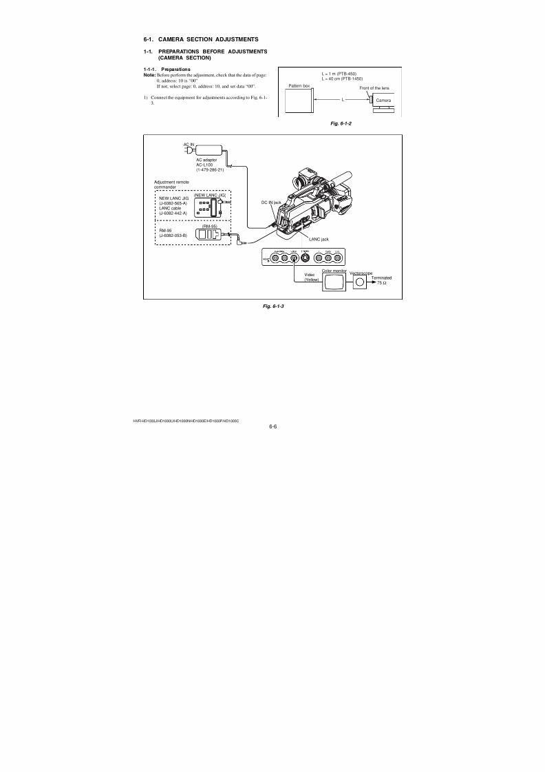
7/18/2019 SONY+HVR-HD1000 SERVICE MANUAL
http://slidepdf.com/reader/full/sonyhvr-hd1000-service-manual 138/4255-27
Ref. No. Part No. Description Ref. No. Part No. Description
HVR-HD1000J/HD1000U/HD1000N/HD1000E/HD1000P/HD1000C
C2923 1-164-874-11 CERAMIC CHIP 100PF 5% 50V
C2924 1-164-874-11 CERAMIC CHIP 100PF 5% 50V
C2925 1-125-777-11 CERAMIC CHIP 0.1uF 10% 10V
C2926 1-125-777-11 CERAMIC CHIP 0.1uF 10% 10V
C2927 1-117-919-11 TANTAL. CHIP 10uF 20% 6.3V
C2928 1-165-908-11 CERAMIC CHIP 1uF 10% 10VC2929 1-165-908-11 CERAMIC CHIP 1uF 10% 10V
C2930 1-125-777-11 CERAMIC CHIP 0.1uF 10% 10V
C2931 1-127-895-91 TANTAL. CHIP 22uF 20% 4V
C2932 1-117-919-11 TANTAL. CHIP 10uF 20% 6.3V
C2933 1-125-777-11 CERAMIC CHIP 0.1uF 10% 10V
C2940 1-125-777-11 CERAMIC CHIP 0.1uF 10% 10V
C2941 1-125-777-11 CERAMIC CHIP 0.1uF 10% 10V
C3001 1-125-777-11 CERAMIC CHIP 0.1uF 10% 10V
C3002 1-125-777-11 CERAMIC CHIP 0.1uF 10% 10V
C3003 1-165-989-11 CERAMIC CHIP 10uF 10% 6.3V
C3004 1-165-989-11 CERAMIC CHIP 10uF 10% 6.3V
C3005 1-165-989-11 CERAMIC CHIP 10uF 10% 6.3V
C3006 1-165-989-11 CERAMIC CHIP 10uF 10% 6.3V
C3007 1-165-989-11 CERAMIC CHIP 10uF 10% 6.3V
C3008 1-165-884-11 CERAMIC CHIP 2.2uF 10% 6.3V
C3009 1-165-884-11 CERAMIC CHIP 2.2uF 10% 6.3V
C3010 1-100-567-81 CERAMIC CHIP 0.01uF 10% 25V
(NTSC: HD1000J /HD1000U/HD1000N)
C3011 1-112-746-11 CERAMIC CHIP 4.7uF 10% 6.3V
C3012 1-100-567-81 CERAMIC CHIP 0.01uF 10% 25V
C3013 1-165-989-11 CERAMIC CHIP 10uF 10% 6.3V
C3014 1-125-777-11 CERAMIC CHIP 0.1uF 10% 10V
C3015 1-125-777-11 CERAMIC CHIP 0.1uF 10% 10V
C3016 1-165-989-11 CERAMIC CHIP 10uF 10% 6.3V
C3017 1-100-567-81 CERAMIC CHIP 0.01uF 10% 25V
C3018 1-112-746-11 CERAMIC CHIP 4.7uF 10% 6.3V
C3019 1-112-746-11 CERAMIC CHIP 4.7uF 10% 6.3V
C3020 1-165-908-11 CERAMIC CHIP 1uF 10% 10V
C3021 1-112-746-11 CERAMIC CHIP 4.7uF 10% 6.3V
C3022 1-125-777-11 CERAMIC CHIP 0.1uF 10% 10V
C3023 1-125-777-11 CERAMIC CHIP 0.1uF 10% 10V
C3024 1-165-908-11 CERAMIC CHIP 1uF 10% 10V
C3025 1-165-908-11 CERAMIC CHIP 1uF 10% 10V
C3026 1-125-777-11 CERAMIC CHIP 0.1uF 10% 10V
C3027 1-125-777-11 CERAMIC CHIP 0.1uF 10% 10V
C3028 1-165-908-11 CERAMIC CHIP 1uF 10% 10V
C3029 1-165-908-11 CERAMIC CHIP 1uF 10% 10V
C3030 1-112-746-11 CERAMIC CHIP 4.7uF 10% 6.3V
C3031 1-165-908-11 CERAMIC CHIP 1uF 10% 10V
C3032 1-165-908-11 CERAMIC CHIP 1uF 10% 10V
C3033 1-165-908-11 CERAMIC CHIP 1uF 10% 10V
C3034 1-165-989-11 CERAMIC CHIP 10uF 10% 6.3V
C3035 1-112-746-11 CERAMIC CHIP 4.7uF 10% 6.3V
C3036 1-165-908-11 CERAMIC CHIP 1uF 10% 10V
C3037 1-112-746-11 CERAMIC CHIP 4.7uF 10% 6.3V
C3038 1-112-746-11 CERAMIC CHIP 4.7uF 10% 6.3V
C3039 1-165-908-11 CERAMIC CHIP 1uF 10% 10V
C3040 1-165-908-11 CERAMIC CHIP 1uF 10% 10V
C3041 1-165-908-11 CERAMIC CHIP 1uF 10% 10V
C3042 1-125-777-11 CERAMIC CHIP 0.1uF 10% 10V
C3043 1-100-539-91 TANTAL. CHIP 47uF 20% 6.3V
C3044 1-100-539-91 TANTAL. CHIP 47uF 20% 6.3V
C3100 1-125-777-11 CERAMIC CHIP 0.1uF 10% 10V
C3102 1-125-777-11 CERAMIC CHIP 0.1uF 10% 10V
C3105 1-125-777-11 CERAMIC CHIP 0.1uF 10% 10V
C3107 1-125-777-11 CERAMIC CHIP 0.1uF 10% 10V
C3109 1-125-777-11 CERAMIC CHIP 0.1uF 10% 10V
C3110 1-125-777-11 CERAMIC CHIP 0.1uF 10% 10VC3111 1-125-777-11 CERAMIC CHIP 0.1uF 10% 10V
C3112 1-125-777-11 CERAMIC CHIP 0.1uF 10% 10V
C3113 1-165-989-11 CERAMIC CHIP 10uF 10% 6.3V
C3114 1-165-989-11 CERAMIC CHIP 10uF 10% 6.3V
C3115 1-165-989-11 CERAMIC CHIP 10uF 10% 6.3V
C3202 1-125-777-11 CERAMIC CHIP 0.1uF 10% 10V
C3203 1-125-777-11 CERAMIC CHIP 0.1uF 10% 10V
C3204 1-125-777-11 CERAMIC CHIP 0.1uF 10% 10V
C3205 1-125-777-11 CERAMIC CHIP 0.1uF 10% 10V
C3206 1-100-567-81 CERAMIC CHIP 0.01uF 10% 25V
C3207 1-127-715-11 CERAMIC CHIP 0.22uF 10% 16V
C3209 1-127-715-11 CERAMIC CHIP 0.22uF 10% 16VC3210 1-165-989-11 CERAMIC CHIP 10uF 10% 6.3V
C3211 1-165-989-11 CERAMIC CHIP 10uF 10% 6.3V
C3212 1-165-989-11 CERAMIC CHIP 10uF 10% 6.3V
C3401 1-165-989-11 CERAMIC CHIP 10uF 10% 6.3V
C3402 1-164-928-11 CERAMIC CHIP 270PF 5% 16V
C3403 1-165-908-11 CERAMIC CHIP 1uF 10% 10V
C3404 1-112-746-11 CERAMIC CHIP 4.7uF 10% 6.3V
C3405 1-125-777-11 CERAMIC CHIP 0.1uF 10% 10V
C3407 1-165-908-11 CERAMIC CHIP 1uF 10% 10V
C3409 1-125-777-11 CERAMIC CHIP 0.1uF 10% 10V
C3411 1-164-852-11 CERAMIC CHIP 12PF 5% 50V
C3412 1-164-852-11 CERAMIC CHIP 12PF 5% 50V
C3414 1-165-908-11 CERAMIC CHIP 1uF 10% 10V
C3415 1-125-777-11 CERAMIC CHIP 0.1uF 10% 10V
C3416 1-125-777-11 CERAMIC CHIP 0.1uF 10% 10V
C3418 1-125-777-11 CERAMIC CHIP 0.1uF 10% 10V
C3420 1-165-908-11 CERAMIC CHIP 1uF 10% 10V
C3701 1-165-908-11 CERAMIC CHIP 1uF 10% 10V
C3702 1-107-826-11 CERAMIC CHIP 0.1uF 10% 16V
C3703 1-100-567-81 CERAMIC CHIP 0.01uF 10% 25V
C3704 1-100-567-81 CERAMIC CHIP 0.01uF 10% 25V
C3705 1-100-567-81 CERAMIC CHIP 0.01uF 10% 25V
C3706 1-164-739-11 CERAMIC CHIP 560PF 5% 50V
C3707 1-127-895-91 TANTAL. CHIP 22uF 20% 4V
C3708 1-165-989-11 CERAMIC CHIP 10uF 10% 6.3V
C3710 1-127-760-11 CERAMIC CHIP 4.7uF 10% 6.3V
C3712 1-127-760-11 CERAMIC CHIP 4.7uF 10% 6.3V
C3713 1-125-889-11 CERAMIC CHIP 2.2uF 10% 10V
C3714 1-165-989-11 CERAMIC CHIP 10uF 10% 6.3V
C3715 1-125-889-11 CERAMIC CHIP 2.2uF 10% 10V
C3716 1-125-777-11 CERAMIC CHIP 0.1uF 10% 10V
C4401 1-100-567-81 CERAMIC CHIP 0.01uF 10% 25V
C4402 1-100-567-81 CERAMIC CHIP 0.01uF 10% 25V
C4403 1-164-850-11 CERAMIC CHIP 10PF 0.5PF 50V
C4404 1-164-850-11 CERAMIC CHIP 10PF 0.5PF 50V
C4406 1-125-777-11 CERAMIC CHIP 0.1uF 10% 10V
C4407 1-125-777-11 CERAMIC CHIP 0.1uF 10% 10VC4408 1-125-777-11 CERAMIC CHIP 0.1uF 10% 10V
C4409 1-125-777-11 CERAMIC CHIP 0.1uF 10% 10V
VC-500Ver. 1.3 2008.12The changed portions fromVer. 1.2 are shown in blue.
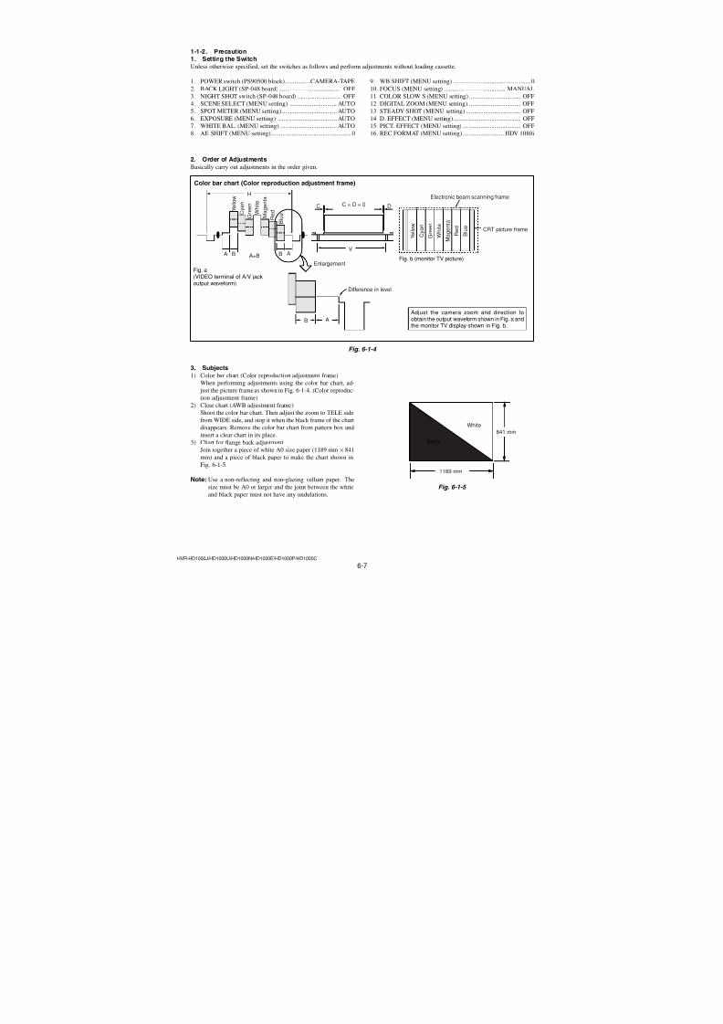
7/18/2019 SONY+HVR-HD1000 SERVICE MANUAL
http://slidepdf.com/reader/full/sonyhvr-hd1000-service-manual 139/4255-28
Ref. No. Part No. Description Ref. No. Part No. Description
HVR-HD1000J/HD1000U/HD1000N/HD1000E/HD1000P/HD1000C
C4410 1-125-777-11 CERAMIC CHIP 0.1uF 10% 10V
C4411 1-125-777-11 CERAMIC CHIP 0.1uF 10% 10V
C4412 1-165-908-11 CERAMIC CHIP 1uF 10% 10V
C4413 1-165-908-11 CERAMIC CHIP 1uF 10% 10V
C4416 1-100-505-11 CERAMIC CHIP 0.1uF 20% 16V
C4417 1-100-505-11 CERAMIC CHIP 0.1uF 20% 16VC4418 1-100-567-81 CERAMIC CHIP 0.01uF 10% 25V
C4419 1-100-567-81 CERAMIC CHIP 0.01uF 10% 25V
C4601 1-107-819-11 CERAMIC CHIP 0.022uF 10% 16V
C4602 1-165-908-11 CERAMIC CHIP 1uF 10% 10V
C4603 1-125-777-11 CERAMIC CHIP 0.1uF 10% 10V
C4604 1-165-989-11 CERAMIC CHIP 10uF 10% 6.3V
C4605 1-165-884-11 CERAMIC CHIP 2.2uF 10% 6.3V
C4606 1-119-923-11 CERAMIC CHIP 0.047uF 10% 10V
C4607 1-165-908-11 CERAMIC CHIP 1uF 10% 10V
C4608 1-125-777-11 CERAMIC CHIP 0.1uF 10% 10V
C4609 1-100-352-91 CERAMIC CHIP 1uF 20% 16V
C4610 1-125-777-11 CERAMIC CHIP 0.1uF 10% 10V
C4611 1-165-908-11 CERAMIC CHIP 1uF 10% 10VC4613 1-165-908-11 CERAMIC CHIP 1uF 10% 10V
C4614 1-125-777-11 CERAMIC CHIP 0.1uF 10% 10V
C4615 1-125-777-11 CERAMIC CHIP 0.1uF 10% 10V
C4616 1-165-989-11 CERAMIC CHIP 10uF 10% 6.3V
C4617 1-125-777-11 CERAMIC CHIP 0.1uF 10% 10V
C4618 1-165-908-11 CERAMIC CHIP 1uF 10% 10V
C4619 1-165-908-11 CERAMIC CHIP 1uF 10% 10V
C4620 1-165-908-11 CERAMIC CHIP 1uF 10% 10V
C4621 1-165-908-11 CERAMIC CHIP 1uF 10% 10V
C4622 1-165-908-11 CERAMIC CHIP 1uF 10% 10V
C4623 1-127-772-81 CERAMIC CHIP 0.033uF 10% 10V
C4624 1-107-819-11 CERAMIC CHIP 0.022uF 10% 16V
C4625 1-165-875-11 CERAMIC CHIP 10uF 10% 10V
C4626 1-165-908-11 CERAMIC CHIP 1uF 10% 10V
C4627 1-165-875-11 CERAMIC CHIP 10uF 10% 10V
C4628 1-165-908-11 CERAMIC CHIP 1uF 10% 10V
C4629 1-165-875-11 CERAMIC CHIP 10uF 10% 10V
C4630 1-165-875-11 CERAMIC CHIP 10uF 10% 10V
C4631 1-165-908-11 CERAMIC CHIP 1uF 10% 10V
C4632 1-165-908-11 CERAMIC CHIP 1uF 10% 10V
C4633 1-165-908-11 CERAMIC CHIP 1uF 10% 10V
C4634 1-165-908-11 CERAMIC CHIP 1uF 10% 10V
C4635 1-165-908-11 CERAMIC CHIP 1uF 10% 10V
C4636 1-165-908-11 CERAMIC CHIP 1uF 10% 10V
C4637 1-100-591-91 CERAMIC CHIP 1uF 10% 25V
C4638 1-127-760-11 CERAMIC CHIP 4.7uF 10% 6.3V
C4640 1-165-989-11 CERAMIC CHIP 10uF 10% 6.3V
C4641 1-165-989-11 CERAMIC CHIP 10uF 10% 6.3V
C4642 1-165-989-11 CERAMIC CHIP 10uF 10% 6.3V
C4643 1-165-989-11 CERAMIC CHIP 10uF 10% 6.3V
C4644 1-165-989-11 CERAMIC CHIP 10uF 10% 6.3V
C4645 1-165-989-11 CERAMIC CHIP 10uF 10% 6.3V
C4646 1-165-989-11 CERAMIC CHIP 10uF 10% 6.3V
C4647 1-165-989-11 CERAMIC CHIP 10uF 10% 6.3V
C4648 1-125-889-11 CERAMIC CHIP 2.2uF 10% 10V
C4649 1-125-889-11 CERAMIC CHIP 2.2uF 10% 10V
C4650 1-165-989-11 CERAMIC CHIP 10uF 10% 6.3V
C4651 1-165-989-11 CERAMIC CHIP 10uF 10% 6.3V
C4653 1-165-884-11 CERAMIC CHIP 2.2uF 10% 6.3V
C4654 1-165-989-11 CERAMIC CHIP 10uF 10% 6.3V
C4655 1-165-989-11 CERAMIC CHIP 10uF 10% 6.3V
C4656 1-165-989-11 CERAMIC CHIP 10uF 10% 6.3V
C4657 1-127-760-11 CERAMIC CHIP 4.7uF 10% 6.3V
C4659 1-127-760-11 CERAMIC CHIP 4.7uF 10% 6.3V
C4661 1-165-884-11 CERAMIC CHIP 2.2uF 10% 6.3VC4662 1-125-827-91 CERAMIC CHIP 1uF 10% 25V
C4667 1-165-989-11 CERAMIC CHIP 10uF 10% 6.3V
C4669 1-100-503-11 CERAMIC CHIP 4.7uF 20% 10V
C4670 1-100-503-11 CERAMIC CHIP 4.7uF 20% 10V
C4671 1-165-884-11 CERAMIC CHIP 2.2uF 10% 6.3V
C4672 1-165-884-11 CERAMIC CHIP 2.2uF 10% 6.3V
C4673 1-127-715-11 CERAMIC CHIP 0.22uF 10% 16V
C4674 1-165-908-11 CERAMIC CHIP 1uF 10% 10V
C4675 1-165-908-11 CERAMIC CHIP 1uF 10% 10V
C4676 1-164-862-11 CERAMIC CHIP 33PF 5% 50V
C4677 1-107-823-11 CERAMIC CHIP 0.47uF 10% 16V
C4679 1-107-826-11 CERAMIC CHIP 0.1uF 10% 16VC4680 1-165-908-11 CERAMIC CHIP 1uF 10% 10V
C4801 1-125-777-11 CERAMIC CHIP 0.1uF 10% 10V
C4802 1-164-858-11 CERAMIC CHIP 22PF 5% 50V
C4803 1-100-567-81 CERAMIC CHIP 0.01uF 10% 25V
C4804 1-100-567-81 CERAMIC CHIP 0.01uF 10% 25V
C4805 1-164-937-11 CERAMIC CHIP 0.001uF 10% 50V
C4806 1-164-937-11 CERAMIC CHIP 0.001uF 10% 50V
C4807 1-100-567-81 CERAMIC CHIP 0.01uF 10% 25V
C4808 1-165-908-11 CERAMIC CHIP 1uF 10% 10V
C4809 1-100-505-11 CERAMIC CHIP 0.1uF 20% 16V
C4810 1-119-923-11 CERAMIC CHIP 0.047uF 10% 10V
C4811 1-119-923-11 CERAMIC CHIP 0.047uF 10% 10V
C4812 1-100-567-81 CERAMIC CHIP 0.01uF 10% 25V
C4813 1-125-777-11 CERAMIC CHIP 0.1uF 10% 10V
C4814 1-125-777-11 CERAMIC CHIP 0.1uF 10% 10V
C4815 1-100-567-81 CERAMIC CHIP 0.01uF 10% 25V
C4816 1-125-777-11 CERAMIC CHIP 0.1uF 10% 10V
C4818 1-125-777-11 CERAMIC CHIP 0.1uF 10% 10V
C4819 1-125-777-11 CERAMIC CHIP 0.1uF 10% 10V
C4820 1-125-777-11 CERAMIC CHIP 0.1uF 10% 10V
C4821 1-107-819-11 CERAMIC CHIP 0.022uF 10% 16V
C4822 1-165-908-11 CERAMIC CHIP 1uF 10% 10V
C4823 1-165-908-11 CERAMIC CHIP 1uF 10% 10V
C4824 1-165-176-11 CERAMIC CHIP 0.047uF 10% 16V
C4825 1-125-777-11 CERAMIC CHIP 0.1uF 10% 10V
C4826 1-165-908-11 CERAMIC CHIP 1uF 10% 10V
C4827 1-125-777-11 CERAMIC CHIP 0.1uF 10% 10V
C4828 1-100-567-81 CERAMIC CHIP 0.01uF 10% 25V
C4829 1-100-505-11 CERAMIC CHIP 0.1uF 20% 16V
C4830 1-164-935-11 CERAMIC CHIP 470PF 10% 50V
C4831 1-125-777-11 CERAMIC CHIP 0.1uF 10% 10V
C4832 1-164-935-11 CERAMIC CHIP 470PF 10% 50V
C4833 1-164-935-11 CERAMIC CHIP 470PF 10% 50V
C4834 1-125-777-11 CERAMIC CHIP 0.1uF 10% 10V
C4835 1-164-935-11 CERAMIC CHIP 470PF 10% 50V
C4836 1-125-777-11 CERAMIC CHIP 0.1uF 10% 10V
C4837 1-164-942-11 CERAMIC CHIP 0.0068uF 10% 16VC4838 1-164-942-11 CERAMIC CHIP 0.0068uF 10% 16V
C4839 1-100-567-81 CERAMIC CHIP 0.01uF 10% 25V
VC-500
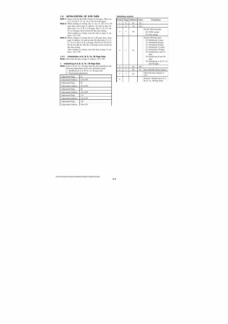
7/18/2019 SONY+HVR-HD1000 SERVICE MANUAL
http://slidepdf.com/reader/full/sonyhvr-hd1000-service-manual 140/4255-29
Ref. No. Part No. Description Ref. No. Part No. Description
HVR-HD1000J/HD1000U/HD1000N/HD1000E/HD1000P/HD1000C
C4901 1-100-567-81 CERAMIC CHIP 0.01uF 10% 25V
C4902 1-165-989-11 CERAMIC CHIP 10uF 10% 6.3V
C4903 1-165-989-11 CERAMIC CHIP 10uF 10% 6.3V
C4904 1-125-777-11 CERAMIC CHIP 0.1uF 10% 10V
C4905 1-125-891-11 CERAMIC CHIP 0.47uF 10% 10V
C4906 1-125-777-11 CERAMIC CHIP 0.1uF 10% 10VC4907 1-125-891-11 CERAMIC CHIP 0.47uF 10% 10V
C4908 1-100-567-81 CERAMIC CHIP 0.01uF 10% 25V
C4909 1-100-567-81 CERAMIC CHIP 0.01uF 10% 25V
C4910 1-125-777-11 CERAMIC CHIP 0.1uF 10% 10V
C4911 1-125-777-11 CERAMIC CHIP 0.1uF 10% 10V
C4912 1-125-777-11 CERAMIC CHIP 0.1uF 10% 10V
C4913 1-125-777-11 CERAMIC CHIP 0.1uF 10% 10V
C4915 1-125-777-11 CERAMIC CHIP 0.1uF 10% 10V
C5004 1-100-567-81 CERAMIC CHIP 0.01uF 10% 25V
C5005 1-100-567-81 CERAMIC CHIP 0.01uF 10% 25V
C5006 1-125-777-11 CERAMIC CHIP 0.1uF 10% 10V
C5007 1-100-567-81 CERAMIC CHIP 0.01uF 10% 25V
C5008 1-164-850-11 CERAMIC CHIP 10PF 0.5PF 50VC5010 1-125-777-11 CERAMIC CHIP 0.1uF 10% 10V
C5011 1-164-852-11 CERAMIC CHIP 12PF 5% 50V
C5012 1-100-567-81 CERAMIC CHIP 0.01uF 10% 25V
C5013 1-125-777-11 CERAMIC CHIP 0.1uF 10% 10V
C5015 1-119-750-11 TANTAL. CHIP 22uF 20% 6.3V
C5016 1-100-567-81 CERAMIC CHIP 0.01uF 10% 25V
C5017 1-100-567-81 CERAMIC CHIP 0.01uF 10% 25V
C5018 1-125-777-11 CERAMIC CHIP 0.1uF 10% 10V
C5102 1-125-777-11 CERAMIC CHIP 0.1uF 10% 10V
C5104 1-125-777-11 CERAMIC CHIP 0.1uF 10% 10V
C5106 1-125-777-11 CERAMIC CHIP 0.1uF 10% 10V
C5107 1-125-777-11 CERAMIC CHIP 0.1uF 10% 10V
C5108 1-125-777-11 CERAMIC CHIP 0.1uF 10% 10V
C5110 1-125-777-11 CERAMIC CHIP 0.1uF 10% 10V
C5113 1-125-777-11 CERAMIC CHIP 0.1uF 10% 10V
C5115 1-125-777-11 CERAMIC CHIP 0.1uF 10% 10V
C5118 1-125-777-11 CERAMIC CHIP 0.1uF 10% 10V
C5119 1-125-777-11 CERAMIC CHIP 0.1uF 10% 10V
C5120 1-125-777-11 CERAMIC CHIP 0.1uF 10% 10V
C5122 1-100-415-91 CERAMIC CHIP 0.47uF 10% 6.3V
C5125 1-164-874-11 CERAMIC CHIP 100PF 5% 50V
C5127 1-125-777-11 CERAMIC CHIP 0.1uF 10% 10V
C5134 1-165-989-11 CERAMIC CHIP 10uF 10% 6.3V
C5135 1-119-750-11 TANTAL. CHIP 22uF 20% 6.3V
C5136 1-165-908-11 CERAMIC CHIP 1uF 10% 10V
C5201 1-100-505-11 CERAMIC CHIP 0.1uF 20% 16V
C5202 1-100-505-11 CERAMIC CHIP 0.1uF 20% 16V
C5203 1-119-750-11 TANTAL. CHIP 22uF 20% 6.3V
C5204 1-165-908-11 CERAMIC CHIP 1uF 10% 10V
C5206 1-165-908-11 CERAMIC CHIP 1uF 10% 10V
C5209 1-100-567-81 CERAMIC CHIP 0.01uF 10% 25V
< CONNECTOR >
* CN1001 1-816-646-51 FFC/FPC CONNECTOR (LIF) 16P
CN1003 1-779-332-51 CONNECTOR, FFC/FPC 16P
* CN1004 1-816-645-51 FFC/FPC CONNECTOR (LIF) 14P
* CN1006 1-816-645-51 FFC/FPC CONNECTOR (LIF) 14P* CN1007 1-817-544-71 CONNECTOR, FPC (ZIF) 39P
* CN1009 1-816-654-51 FFC/FPC CONNECTOR (LIF) 6P
* CN1010 1-820-729-61 CONNECTOR, FPC (ZIF) 51P
* CN1012 1-818-087-51 CONNECTOR, FFC/FPC (LIF) 26P
* CN1015 1-816-648-51 FFC/FPC CONNECTOR (LIF) 20P
* CN1017 1-819-778-61 CONNECTOR, FPC (ZIF) 33P
CN1201 1-820-560-11 CONNECTOR, COAXIAL (RECEPTACLE) 40P
* CN3202 1-816-648-51 FFC/FPC CONNECTOR (LIF) 20P* CN3701 1-816-648-51 FFC/FPC CONNECTOR (LIF) 20P
* CN4801 1-818-818-71 CONNECTOR, FPC (ZIF) 29P
* CN4802 1-816-643-51 FFC/FPC CONNECTOR (LIF) 10P
* CN4803 1-817-829-71 CONNECTOR, FPC (ZIF) 27P
* CN4901 1-816-643-51 FFC/FPC CONNECTOR (LIF) 10P
< DIODE >
D1010 8-719-074-67 DIODE EDZ-TE61-5.6B
* D1011 6-501-956-01 DIODE MAZS068G08S0
D4601 8-719-081-19 DIODE 1SS383 (T5RSONY1)
D4602 8-719-027-76 DIODE 1SS357-TPH3
D4603 8-719-069-29 DIODE RB520S-30TE61
D4604 6-500-168-01 DIODE MA4SD1000LS0
D4606 8-719-027-76 DIODE 1SS357-TPH3
* D4607 6-501-961-01 DIODE MAZS120G08S0
< FUSE >
0F4601 1-576-406-21 FUSE, MICRO (1608) (1.4A/32V)
0F4602 1-576-406-21 FUSE, MICRO (1608) (1.4A/32V)
0F4603 1-576-406-21 FUSE, MICRO (1608) (1.4A/32V)
0F4604 1-576-406-21 FUSE, MICRO (1608) (1.4A/32V)
0F4605 1-576-406-21 FUSE, MICRO (1608) (1.4A/32V)
0F4606 1-576-406-21 FUSE, MICRO (1608) (1.4A/32V)
0F4607 1-576-406-21 FUSE, MICRO (1608) (1.4A/32V)
< FERRITE BEAD >
FB1001 1-400-927-31 BEAD, FERRITE (1005)
FB1002 1-400-927-31 BEAD, FERRITE (1005)
FB1701 1-400-331-11 FERRITE, EMI (SMD) (1005)
FB1702 1-400-331-11 FERRITE, EMI (SMD) (1005)
FB1802 1-469-082-21 INDUCTOR, FERRITE BEAD (1005)
FB1901 1-400-619-11 BEAD, FERRITE (CHIP) (1608)
FB2002 1-400-331-11 FERRITE, EMI (SMD) (1005)
FB2101 1-400-331-11 FERRITE, EMI (SMD) (1005)
FB2102 1-400-331-11 FERRITE, EMI (SMD) (1005)
FB2103 1-400-331-11 FERRITE, EMI (SMD) (1005)
FB2104 1-400-331-11 FERRITE, EMI (SMD) (1005)
FB2201 1-400-331-11 FERRITE, EMI (SMD) (1005)
FB2401 1-469-082-21 INDUCTOR, FERRITE BEAD (1005)
FB3001 1-469-082-21 INDUCTOR, FERRITE BEAD (1005)
FB3401 1-400-619-11 BEAD, FERRITE (CHIP) (1608)
FB3701 1-400-619-11 BEAD, FERRITE (CHIP) (1608)
FB4401 1-469-082-21 INDUCTOR, FERRITE BEAD (1005)
FB5101 1-469-581-21 INDUCTOR, FERRITE BEAD (1005)
FB5102 1-400-331-11 FERRITE, EMI (SMD) (1005)
FB5103 1-400-331-11 FERRITE, EMI (SMD) (1005)
FB5105 1-400-331-11 FERRITE, EMI (SMD) (1005)
FB5106 1-400-331-11 FERRITE, EMI (SMD) (1005)
FB5107 1-469-581-21 INDUCTOR, FERRITE BEAD (1005)FB5108 1-469-581-21 INDUCTOR, FERRITE BEAD (1005)
FB5201 1-400-331-11 FERRITE, EMI (SMD) (1005)
• Refer to page 5-1 for mark 0.
VC-500
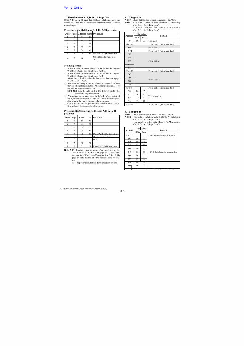
7/18/2019 SONY+HVR-HD1000 SERVICE MANUAL
http://slidepdf.com/reader/full/sonyhvr-hd1000-service-manual 141/4255-30
Ref. No. Part No. Description Ref. No. Part No. Description
HVR-HD1000J/HD1000U/HD1000N/HD1000E/HD1000P/HD1000C
FB5202 1-400-331-11 FERRITE, EMI (SMD) (1005)
< FILTER >
FL1901 1-234-939-21 FILTER, EMI REMOVAL (SMD)
FL3100 1-234-939-21 FILTER, EMI REMOVAL (SMD)
FL3101 1-234-939-21 FILTER, EMI REMOVAL (SMD)FL3102 1-234-939-21 FILTER, EMI REMOVAL (SMD)
FL3201 1-234-939-21 FILTER, EMI REMOVAL (SMD)
< IC >
* IC1001 6-708-445-01 IC R1114Q291D-TR-FA
* IC1201 6-710-806-01 IC VSP2436ZWDR
* IC1301 6-710-806-01 IC VSP2436ZWDR
IC1701 6-708-135-01 IC HD74ALVC2G74USE-E
* IC1702 6-710-008-01 IC CXD9886GG
IC1801 6-807-916-01 IC MB91195ABGL-G-252-ERE1
* IC1802 6-710-155-01 IC AK6514CAM-E2
* IC1901 6-710-438-01 IC EDS2532JEBH-75TT-E
IC2001 6-708-108-01 IC TLS26A100PFBR* IC2101 6-710-743-01 IC S4DF006X02-Y071-K12K4C
* IC2201 8-753-276-37 IC CXD3195AGG-T6
* IC2401 6-710-306-01 IC HYE18M256320CFX-7.5
IC2402 (Not supplied) IC S29AL016D70BFI013
* IC2701 6-710-783-01 IC MB8AA1121BGL-G-ERE1
IC2901 6-707-725-01 IC BH7875GLU-E2
IC2902 6-701-112-01 IC DS1801E-02V+T/R
IC2903 8-759-710-79 IC NJM2107F
* IC2904 6-708-444-01 IC R1114Q281D-TR-FA
IC3001 6-707-435-01 IC AN12921A-VB
* IC3002 6-709-328-01 IC AK4554VL-8-L
IC3101 6-711-003-01 IC T6UL2XBG-0002 (EO2)
* IC3201 6-710-770-01 IC AD9889BBBCZRL-80
IC3202 6-705-338-01 IC TK11250CMCL-G
* IC3401 6-710-516-01 IC SN200507002ZZCR
* IC3701 8-753-242-24 IC CXM3018R-T4
* IC4401 6-807-924-01 IC MB91195ABGL-G-251-ERE1
* IC4601 6-710-636-01 IC MB44C005BBGL-G-ERE1
* IC4602 6-710-254-01 IC LV5254LG-TLM-E
* IC4603 6-708-464-01 IC R1114Q251D-TR-FA
IC4604 8-759-581-11 IC NJM2125F (TE2)
IC4605 6-703-977-01 IC R1114Q331D-TR-FA
IC4801 6-707-428-01 IC BD6639AGLV-E2
IC4901 6-707-432-01 IC TLS26A102PFBR
* IC5001 6-808-391-01 IC MB95005ABGL-G-119-ERE1
* IC5101 6-710-594-01 IC S4LFS33X0-Y070
IC5103 6-702-708-01 IC TC7SZU04AFE (TE85R)
IC5201 6-707-634-01 IC W9816G6CB-7-ER20
IC5202 (Not supplied) IC S99-50031-33-ER
< COIL >
L1201 1-400-588-11 INDUCTOR 10uH
L1202 1-469-555-21 INDUCTOR 10uH
L1301 1-400-588-11 INDUCTOR 10uH
L1302 1-469-555-21 INDUCTOR 10uH
L1701 1-400-353-21 INDUCTOR 22uH
L1702 1-400-588-11 INDUCTOR 10uH
L1703 1-400-588-11 INDUCTOR 10uH
L1704 1-400-588-11 INDUCTOR 10uH
L2001 1-400-588-11 INDUCTOR 10uH
L2002 1-400-588-11 INDUCTOR 10uH
L2003 1-400-588-11 INDUCTOR 10uH
L2101 1-400-675-11 INDUCTOR 10uH
L2102 1-400-676-11 INDUCTOR 22uH
L2103 1-400-588-11 INDUCTOR 10uHL2104 1-400-676-11 INDUCTOR 22uH
L2105 1-400-588-11 INDUCTOR 10uH
L2201 1-400-675-11 INDUCTOR 10uH
L2202 1-400-676-11 INDUCTOR 22uH
L2203 1-400-676-11 INDUCTOR 22uH
L2204 1-400-676-11 INDUCTOR 22uH
L2205 1-400-676-11 INDUCTOR 22uH
L2702 1-400-675-11 INDUCTOR 10uH
L2703 1-400-675-11 INDUCTOR 10uH
L2704 1-400-675-11 INDUCTOR 10uH
L2901 1-400-678-11 INDUCTOR 100uH
L2902 1-400-678-11 INDUCTOR 100uHL3001 1-400-588-11 INDUCTOR 10uH
L3002 1-400-588-11 INDUCTOR 10uH
L3003 1-400-588-11 INDUCTOR 10uH
L3004 1-400-588-11 INDUCTOR 10uH
L3005 1-400-588-11 INDUCTOR 10uH
L3006 1-400-588-11 INDUCTOR 10uH
* L3201 1-400-674-21 INDUCTOR 4.7uH
* L3202 1-400-673-21 INDUCTOR 2.2uH
* L3203 1-400-673-21 INDUCTOR 2.2uH
L3401 1-400-588-11 INDUCTOR 10uH
L3701 1-400-588-11 INDUCTOR 10uH
L3702 1-400-588-11 INDUCTOR 10uH
L3703 1-400-588-11 INDUCTOR 10uH
L4601 1-456-497-11 INDUCTOR 15uH
L4602 1-456-497-11 INDUCTOR 15uH
L4603 1-456-497-11 INDUCTOR 15uH
L4604 1-456-497-11 INDUCTOR 15uH
L4605 1-456-497-11 INDUCTOR 15uH
L4606 1-456-497-11 INDUCTOR 15uH
L4607 1-469-549-21 INDUCTOR 1uH
L4608 1-469-549-21 INDUCTOR 1uH
L4609 1-469-551-21 INDUCTOR 2.2uH
L4610 1-469-549-21 INDUCTOR 1uH
L4611 1-469-549-21 INDUCTOR 1uH
L4612 1-469-549-21 INDUCTOR 1uH
L4614 1-469-555-21 INDUCTOR 10uH
L4615 1-469-551-21 INDUCTOR 2.2uH
L4616 1-469-555-21 INDUCTOR 10uH
L4622 1-456-501-11 INDUCTOR 33uH
L4623 1-456-497-11 INDUCTOR 15uH
L4624 1-469-549-21 INDUCTOR 1uH
L4625 1-469-549-21 INDUCTOR 1uH
L4626 1-456-136-21 INDUCTOR 10uH
L4627 1-456-136-21 INDUCTOR 10uH
L4628 1-469-549-21 INDUCTOR 1uH
L4630 1-469-555-21 INDUCTOR 10uH
L4801 1-400-202-21 INDUCTOR 4.7uHL4901 1-400-588-11 INDUCTOR 10uH
L4902 1-400-588-11 INDUCTOR 10uH
VC-500Ver. 1.3 2008.12The changed portions fromVer. 1.2 are shown in blue.
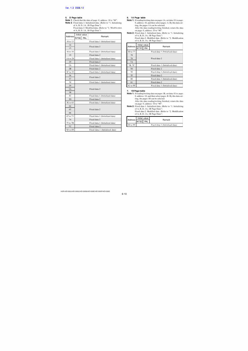
7/18/2019 SONY+HVR-HD1000 SERVICE MANUAL
http://slidepdf.com/reader/full/sonyhvr-hd1000-service-manual 142/4255-31
Ref. No. Part No. Description Ref. No. Part No. Description
HVR-HD1000J/HD1000U/HD1000N/HD1000E/HD1000P/HD1000C
< LINE FILTER >
* LF1002 1-457-217-21 COMMON MODE CHOKE COIL
* LF3201 1-813-880-11 COMMON MODE CHOKE COIL
* LF3202 1-813-880-11 COMMON MODE CHOKE COIL
* LF3203 1-813-880-11 COMMON MODE CHOKE COIL
* LF3204 1-813-880-11 COMMON MODE CHOKE COIL
LF3403 1-457-064-12 COMMON MODE CHOKE COIL
LF5101 1-457-223-11 COMMON MODE CHOKE COIL
< TRANSISTOR >
Q1001 6-550-102-01 TRANSISTOR 2SC5663T2L
Q2101 6-550-232-01 TRANSISTOR 2SA2029T2LQ/R
Q2102 6-550-232-01 TRANSISTOR 2SA2029T2LQ/R
Q2103 6-550-232-01 TRANSISTOR 2SA2029T2LQ/R
Q2104 6-550-232-01 TRANSISTOR 2SA2029T2LQ/R
Q2105 6-550-232-01 TRANSISTOR 2SA2029T2LQ/R
Q2106 6-550-232-01 TRANSISTOR 2SA2029T2LQ/R
Q2107 6-550-232-01 TRANSISTOR 2SA2029T2LQ/RQ3001 8-729-056-73 TRANSISTOR CPH6501-TL-E
Q3002 8-729-054-52 TRANSISTOR UP04216008S0
Q3003 8-729-054-52 TRANSISTOR UP04216008S0
Q3701 8-729-054-48 TRANSISTOR UP04601008S0
Q4601 6-551-442-01 TRANSISTOR TPCP8301 (T5RSONYF)
Q4602 8-729-047-68 TRANSISTOR SSM3K03FE (TPL3)
Q4603 8-729-043-60 TRANSISTOR CPH6102-TL-E
Q4604 6-550-119-01 TRANSISTOR DTC144EMT2L
Q4607 6-550-714-01 TRANSISTOR SCH1406-TL-E
Q4608 6-550-714-01 TRANSISTOR SCH1406-TL-E
Q4609 6-550-713-01 TRANSISTOR SCH2816-TL-E
Q4610 6-550-713-01 TRANSISTOR SCH2816-TL-E
Q4801 6-550-242-01 TRANSISTOR DTC114EMT2L
Q4802 6-550-174-01 TRANSISTOR 2SA2030T2L
Q4803 6-550-237-01 TRANSISTOR 2SC5658T2LQ/R
Q5101 6-550-119-01 TRANSISTOR DTC144EMT2L
Q5103 6-550-119-01 TRANSISTOR DTC144EMT2L
Q5104 6-550-237-01 TRANSISTOR 2SC5658T2LQ/R
Q5108 6-551-338-01 TRANSISTOR UNR31AF00LS0
Q5110 6-550-239-01 TRANSISTOR DTA144EMT2L
Q5111 8-729-053-54 TRANSISTOR HN1A01FE-Y/GR (TPLR3)
Q5112 6-550-174-01 TRANSISTOR 2SA2030T2L
< RESISTOR >
R1009 1-218-953-11 RES-CHIP 1K 5% 1/16W
R1010 1-218-953-11 RES-CHIP 1K 5% 1/16W
R1015 1-218-953-11 RES-CHIP 1K 5% 1/16W
R1016 1-218-953-11 RES-CHIP 1K 5% 1/16W
R1026 1-218-954-11 RES-CHIP 1.2K 5% 1/16W
R1027 1-218-990-81 SHORT CHIP 0
R1028 1-218-951-11 RES-CHIP 680 5% 1/16W
R1037 1-218-959-11 RES-CHIP 3.3K 5% 1/16W
R1214 1-218-953-11 RES-CHIP 1K 5% 1/16W
R1232 1-218-933-11 RES-CHIP 22 5% 1/16W
R1314 1-218-953-11 RES-CHIP 1K 5% 1/16W
R1347 1-218-990-81 SHORT CHIP 0
R1702 1-218-990-81 SHORT CHIP 0(NTSC: HD1000J /HD1000U/HD1000N)
R1704 1-218-990-81 SHORT CHIP 0
(PAL: HD1000E/HD1000P/HD1000C)
R1706 1-218-929-11 RES-CHIP 10 5% 1/16W
R1713 1-218-933-11 RES-CHIP 22 5% 1/16W
R1717 1-218-953-11 RES-CHIP 1K 5% 1/16W
R1722 1-218-961-11 RES-CHIP 4.7K 5% 1/16W
R1725 1-218-990-81 SHORT CHIP 0
R1801 1-218-941-81 RES-CHIP 100 5% 1/16W
R1802 1-218-965-11 RES-CHIP 10K 5% 1/16W
R1804 1-218-965-11 RES-CHIP 10K 5% 1/16W
R1807 1-218-990-81 SHORT CHIP 0
(NTSC: HD1000J /HD1000U/HD1000N)
R1808 1-218-990-81 SHORT CHIP 0
(PAL: HD1000E/HD1000P/HD1000C)
R1809 1-218-973-11 RES-CHIP 47K 5% 1/16W
R1810 1-218-977-11 RES-CHIP 100K 5% 1/16W
R1811 1-218-985-11 RES-CHIP 470K 5% 1/16W
R1812 1-218-953-11 RES-CHIP 1K 5% 1/16W
R1813 1-218-989-11 RES-CHIP 1M 5% 1/16W
R1814 1-218-989-11 RES-CHIP 1M 5% 1/16W
R1815 1-218-973-11 RES-CHIP 47K 5% 1/16W
R1820 1-218-977-11 RES-CHIP 100K 5% 1/16W
R1823 1-218-990-81 SHORT CHIP 0
R1824 1-218-977-11 RES-CHIP 100K 5% 1/16W
R1830 1-218-973-11 RES-CHIP 47K 5% 1/16W
R1906 1-218-977-11 RES-CHIP 100K 5% 1/16W
R1907 1-218-977-11 RES-CHIP 100K 5% 1/16W
R2030 1-208-860-81 METAL CHIP 75 0.5% 1/16W
R2031 1-208-860-81 METAL CHIP 75 0.5% 1/16W
R2032 1-208-860-81 METAL CHIP 75 0.5% 1/16W
R2103 1-218-977-11 RES-CHIP 100K 5% 1/16W
R2105 1-218-990-81 SHORT CHIP 0
R2106 1-208-711-11 METAL CHIP 15K 0.5% 1/16W
R2109 1-218-935-11 RES-CHIP 33 5% 1/16W
R2111 1-218-953-11 RES-CHIP 1K 5% 1/16W
R2115 1-218-935-11 RES-CHIP 33 5% 1/16W
R2116 1-218-965-11 RES-CHIP 10K 5% 1/16W
R2119 1-208-699-11 METAL CHIP 4.7K 0.5% 1/16W
R2120 1-208-715-11 METAL CHIP 22K 0.5% 1/16W
R2121 1-218-990-81 SHORT CHIP 0
R2122 1-218-973-11 RES-CHIP 47K 5% 1/16W
R2123 1-218-965-11 RES-CHIP 10K 5% 1/16W
R2125 1-218-935-11 RES-CHIP 33 5% 1/16W
R2132 1-208-873-81 METAL CHIP 270 0.5% 1/16W
R2133 1-208-873-81 METAL CHIP 270 0.5% 1/16W
R2134 1-208-873-81 METAL CHIP 270 0.5% 1/16W
R2135 1-208-671-11 METAL CHIP 330 0.5% 1/16W
R2136 1-208-671-11 METAL CHIP 330 0.5% 1/16W
R2137 1-208-671-11 METAL CHIP 330 0.5% 1/16W
R2138 1-208-869-11 METAL CHIP 180 0.5% 1/16W
R2139 1-208-869-11 METAL CHIP 180 0.5% 1/16W
R2140 1-208-869-11 METAL CHIP 180 0.5% 1/16W
R2142 1-218-990-81 SHORT CHIP 0
R2143 1-218-990-81 SHORT CHIP 0
R2144 1-218-961-11 RES-CHIP 4.7K 5% 1/16W
R2145 1-218-961-11 RES-CHIP 4.7K 5% 1/16W
R2146 1-218-961-11 RES-CHIP 4.7K 5% 1/16WR2147 1-218-961-11 RES-CHIP 4.7K 5% 1/16W
R2148 1-218-961-11 RES-CHIP 4.7K 5% 1/16W
R2149 1-218-961-11 RES-CHIP 4.7K 5% 1/16W
VC-500Ver. 1.3 2008.12The changed portions fromVer. 1.2 are shown in blue.
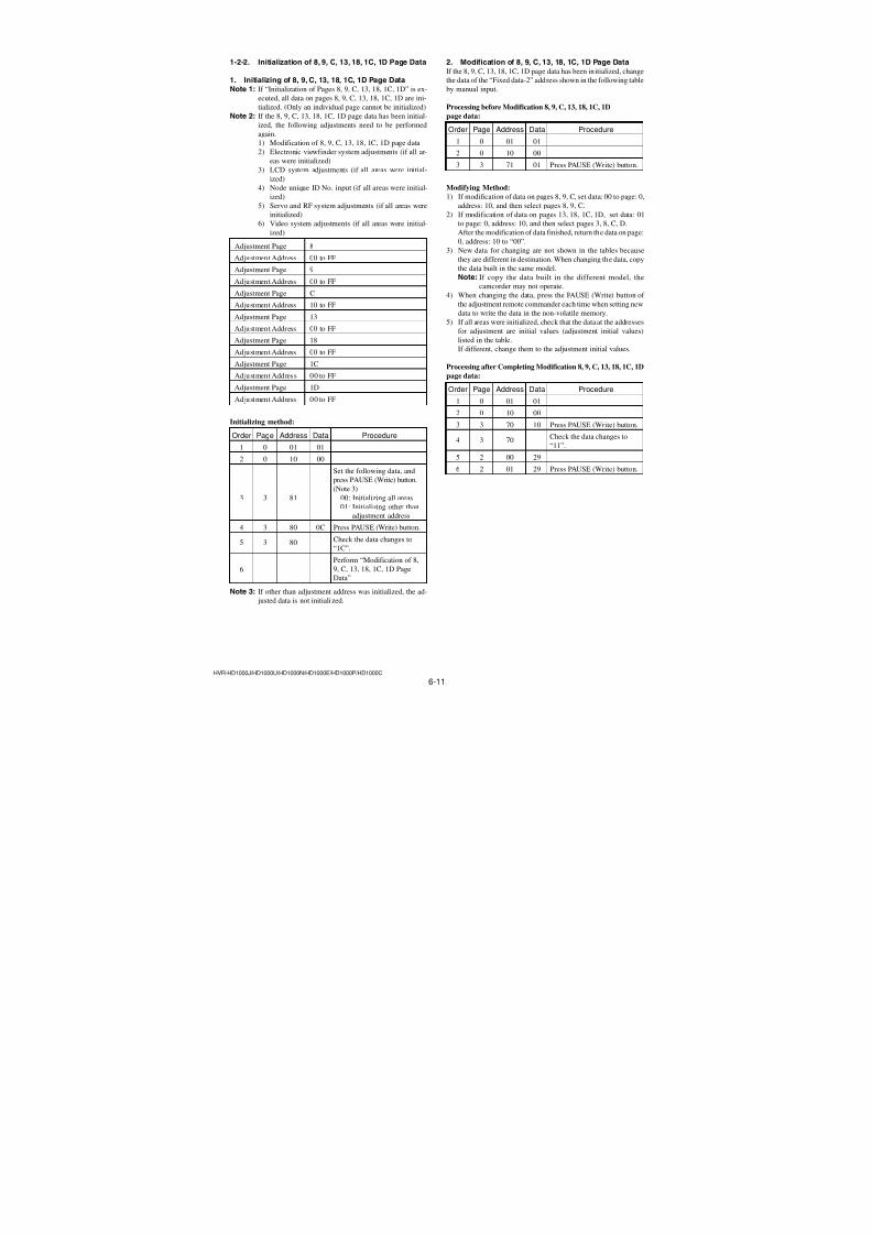
7/18/2019 SONY+HVR-HD1000 SERVICE MANUAL
http://slidepdf.com/reader/full/sonyhvr-hd1000-service-manual 143/4255-32
Ref. No. Part No. Description Ref. No. Part No. Description
HVR-HD1000J/HD1000U/HD1000N/HD1000E/HD1000P/HD1000C
R2150 1-218-953-11 RES-CHIP 1K 5% 1/16W
R2153 1-218-935-11 RES-CHIP 33 5% 1/16W
R2208 1-218-935-11 RES-CHIP 33 5% 1/16W
R2215 1-218-990-81 SHORT CHIP 0
R2216 1-218-977-11 RES-CHIP 100K 5% 1/16W
R2231 1-218-961-11 RES-CHIP 4.7K 5% 1/16W
R2233 1-218-990-81 SHORT CHIP 0
R2235 1-218-990-81 SHORT CHIP 0
R2240 1-218-961-11 RES-CHIP 4.7K 5% 1/16W
R2401 1-216-864-11 SHORT CHIP 0
R2402 1-218-990-81 SHORT CHIP 0
R2707 1-218-990-81 SHORT CHIP 0
R2709 1-218-953-11 RES-CHIP 1K 5% 1/16W
R2711 1-218-941-81 RES-CHIP 100 5% 1/16W
R2712 1-218-941-81 RES-CHIP 100 5% 1/16W
R2713 1-218-953-11 RES-CHIP 1K 5% 1/16W
R2715 1-218-941-81 RES-CHIP 100 5% 1/16W
R2716 1-218-953-11 RES-CHIP 1K 5% 1/16WR2717 1-218-990-81 SHORT CHIP 0
R2720 1-218-963-11 RES-CHIP 6.8K 5% 1/16W
R2732 1-218-990-81 SHORT CHIP 0
R2735 1-218-990-81 SHORT CHIP 0
R2904 1-218-965-11 RES-CHIP 10K 5% 1/16W
R2906 1-218-975-11 RES-CHIP 68K 5% 1/16W
R2911 1-218-990-81 SHORT CHIP 0
R2912 1-218-990-81 SHORT CHIP 0
R2913 1-208-923-11 METAL CHIP 33K 0.5% 1/16W
R2914 1-208-943-11 METAL CHIP 220K 0.5% 1/16W
R2917 1-218-953-11 RES-CHIP 1K 5% 1/16W
R2920 1-218-990-81 SHORT CHIP 0
R2921 1-218-990-81 SHORT CHIP 0
R2922 1-218-963-11 RES-CHIP 6.8K 5% 1/16W
R2923 1-218-953-11 RES-CHIP 1K 5% 1/16W
R2924 1-218-953-11 RES-CHIP 1K 5% 1/16W
R2925 1-218-963-11 RES-CHIP 6.8K 5% 1/16W
R2927 1-218-973-11 RES-CHIP 47K 5% 1/16W
R2928 1-218-973-11 RES-CHIP 47K 5% 1/16W
R2929 1-218-977-11 RES-CHIP 100K 5% 1/16W
R2930 1-218-977-11 RES-CHIP 100K 5% 1/16W
R2945 1-218-990-81 SHORT CHIP 0
R3001 1-208-860-81 METAL CHIP 75 0.5% 1/16W
R3002 1-208-860-81 METAL CHIP 75 0.5% 1/16W
R3003 1-218-977-11 RES-CHIP 100K 5% 1/16W
R3004 1-208-860-81 METAL CHIP 75 0.5% 1/16W
R3006 1-218-961-11 RES-CHIP 4.7K 5% 1/16W
R3007 1-218-941-81 RES-CHIP 100 5% 1/16W
R3008 1-218-941-81 RES-CHIP 100 5% 1/16W
R3009 1-218-965-11 RES-CHIP 10K 5% 1/16W
(NTSC: HD1000J /HD1000U/HD1000N)
R3010 1-218-977-11 RES-CHIP 100K 5% 1/16W
R3011 1-218-973-11 RES-CHIP 47K 5% 1/16W
R3012 1-218-973-11 RES-CHIP 47K 5% 1/16W
R3013 1-218-965-11 RES-CHIP 10K 5% 1/16W
R3014 1-218-965-11 RES-CHIP 10K 5% 1/16W
R3016 1-218-960-11 RES-CHIP 3.9K 5% 1/16WR3017 1-218-971-11 RES-CHIP 33K 5% 1/16W
R3018 1-218-937-11 RES-CHIP 47 5% 1/16W
R3019 1-218-937-11 RES-CHIP 47 5% 1/16W
R3020 1-218-965-11 RES-CHIP 10K 5% 1/16W
R3021 1-218-965-11 RES-CHIP 10K 5% 1/16W
R3203 1-218-937-11 RES-CHIP 47 5% 1/16W
R3204 1-218-937-11 RES-CHIP 47 5% 1/16W
R3205 1-218-937-11 RES-CHIP 47 5% 1/16WR3206 1-218-937-11 RES-CHIP 47 5% 1/16W
R3207 1-218-937-11 RES-CHIP 47 5% 1/16W
R3208 1-218-937-11 RES-CHIP 47 5% 1/16W
R3209 1-218-937-11 RES-CHIP 47 5% 1/16W
R3210 1-218-937-11 RES-CHIP 47 5% 1/16W
R3218 1-218-990-81 SHORT CHIP 0
R3219 1-218-973-11 RES-CHIP 47K 5% 1/16W
R3220 1-218-956-11 RES-CHIP 1.8K 5% 1/16W
R3221 1-218-956-11 RES-CHIP 1.8K 5% 1/16W
R3229 1-208-886-81 METAL CHIP 910 0.5% 1/16W
R3233 1-218-990-81 SHORT CHIP 0
R3234 1-208-720-11 METAL CHIP 36K 0.5% 1/16W
R3401 1-218-965-11 RES-CHIP 10K 5% 1/16W
R3402 1-218-965-11 RES-CHIP 10K 5% 1/16W
R3403 1-208-652-11 METAL CHIP 51 0.5% 1/16W
R3404 1-208-652-11 METAL CHIP 51 0.5% 1/16W
R3405 1-208-652-11 METAL CHIP 51 0.5% 1/16W
R3406 1-208-652-11 METAL CHIP 51 0.5% 1/16W
R3407 1-218-990-81 SHORT CHIP 0
R3408 1-218-953-11 RES-CHIP 1K 5% 1/16W
R3409 1-208-906-81 METAL CHIP 6.2K 0.5% 1/16W
R3412 1-218-953-11 RES-CHIP 1K 5% 1/16W
R3413 1-218-990-81 SHORT CHIP 0
R3701 1-218-975-11 RES-CHIP 68K 5% 1/16W
R3702 1-218-949-11 RES-CHIP 470 5% 1/16W
R3705 1-208-935-11 METAL CHIP 100K 0.5% 1/16W
R3707 1-218-965-11 RES-CHIP 10K 5% 1/16W
R3708 1-208-691-11 METAL CHIP 2.2K 0.5% 1/16W
R3709 1-208-687-11 METAL CHIP 1.5K 0.5% 1/16W
R3711 1-218-957-11 RES-CHIP 2.2K 5% 1/16W
R3712 1-208-861-81 METAL CHIP 82 0.5% 1/16W
R4401 1-218-941-81 RES-CHIP 100 5% 1/16W
R4402 1-218-965-11 RES-CHIP 10K 5% 1/16W
R4403 1-218-965-11 RES-CHIP 10K 5% 1/16W
R4404 1-218-977-11 RES-CHIP 100K 5% 1/16W
R4406 1-218-965-11 RES-CHIP 10K 5% 1/16W
R4407 1-218-965-11 RES-CHIP 10K 5% 1/16W
R4408 1-218-985-11 RES-CHIP 470K 5% 1/16W
R4413 1-218-981-91 RES-CHIP 220K 5% 1/16W
R4414 1-218-975-11 RES-CHIP 68K 5% 1/16W
R4416 1-218-977-11 RES-CHIP 100K 5% 1/16W
R4417 1-218-953-11 RES-CHIP 1K 5% 1/16W
R4418 1-218-953-11 RES-CHIP 1K 5% 1/16W
R4419 1-218-977-11 RES-CHIP 100K 5% 1/16W
R4420 1-218-977-11 RES-CHIP 100K 5% 1/16W
R4421 1-218-977-11 RES-CHIP 100K 5% 1/16W
R4422 1-218-953-11 RES-CHIP 1K 5% 1/16W
R4423 1-218-985-11 RES-CHIP 470K 5% 1/16W
R4601 1-208-931-11 METAL CHIP 68K 0.5% 1/16WR4602 1-218-977-11 RES-CHIP 100K 5% 1/16W
R4603 1-218-989-11 RES-CHIP 1M 5% 1/16W
R4604 1-218-961-11 RES-CHIP 4.7K 5% 1/16W
VC-500Ver. 1.3 2008.12The changed portions fromVer. 1.2 are shown in blue.
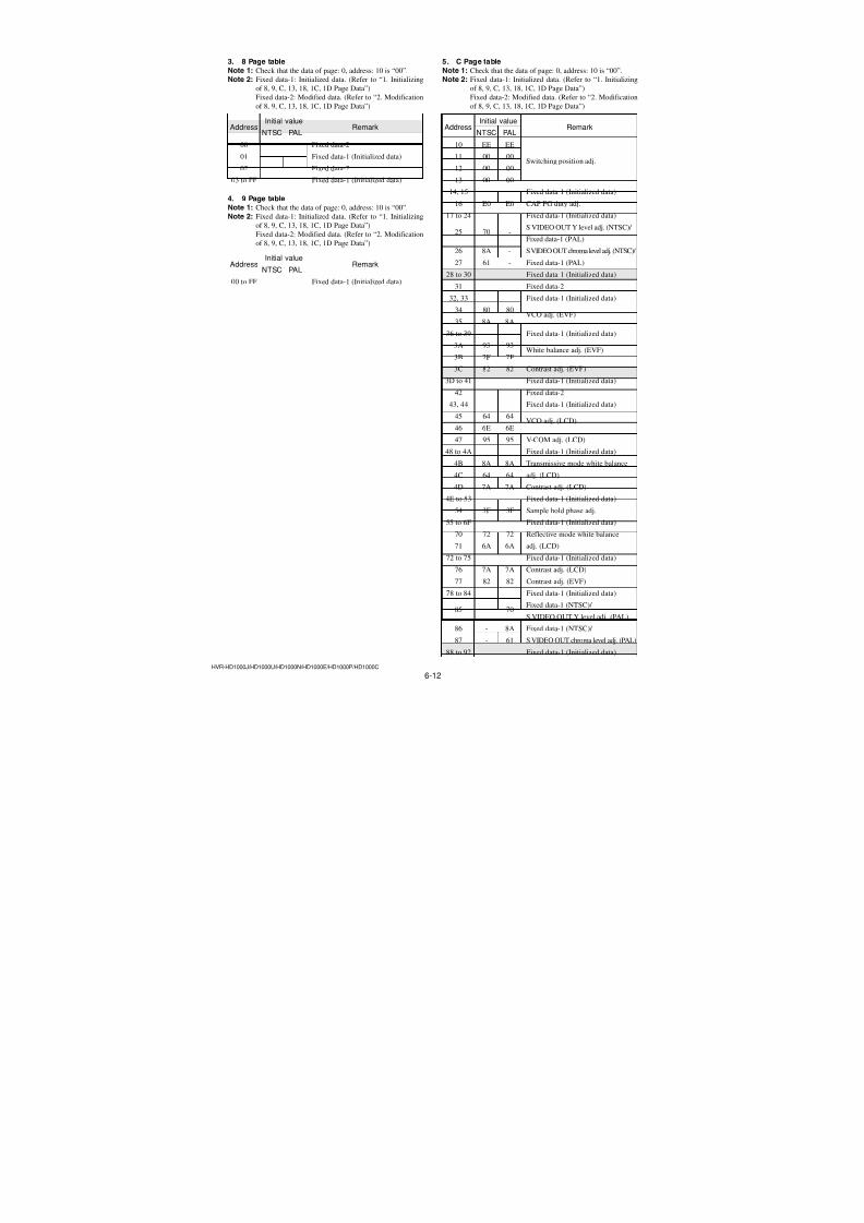
7/18/2019 SONY+HVR-HD1000 SERVICE MANUAL
http://slidepdf.com/reader/full/sonyhvr-hd1000-service-manual 144/4255-33
Ref. No. Part No. Description Ref. No. Part No. Description
HVR-HD1000J/HD1000U/HD1000N/HD1000E/HD1000P/HD1000C
R4605 1-216-150-91 RES-CHIP 10 5% 1/8W
R4607 1-218-953-11 RES-CHIP 1K 5% 1/16W
R4608 1-218-961-11 RES-CHIP 4.7K 5% 1/16W
R4610 1-218-961-11 RES-CHIP 4.7K 5% 1/16W
R4611 1-208-691-11 METAL CHIP 2.2K 0.5% 1/16W
R4612 1-208-889-11 METAL CHIP 1.2K 0.5% 1/16W
R4613 1-208-933-11 METAL CHIP 82K 0.5% 1/16W
R4614 1-208-944-81 METAL CHIP 240K 0.5% 1/16W
R4615 1-216-789-11 METAL CHIP 2.2 5% 1/10W
R4617 1-218-941-81 RES-CHIP 100 5% 1/16W
R4619 1-218-944-11 RES-CHIP 180 5% 1/16W
R4620 1-218-949-11 RES-CHIP 470 5% 1/16W
R4631 1-216-864-11 SHORT CHIP 0
R4675 1-208-711-11 METAL CHIP 15K 0.5% 1/16W
R4676 1-208-933-11 METAL CHIP 82K 0.5% 1/16W
R4683 1-216-295-91 SHORT CHIP 0
R4685 1-216-295-91 SHORT CHIP 0
R4801 1-218-935-11 RES-CHIP 33 5% 1/16WR4802 1-218-935-11 RES-CHIP 33 5% 1/16W
R4803 1-218-953-11 RES-CHIP 1K 5% 1/16W
R4804 1-218-965-11 RES-CHIP 10K 5% 1/16W
R4805 1-218-965-11 RES-CHIP 10K 5% 1/16W
R4806 1-218-953-11 RES-CHIP 1K 5% 1/16W
R4807 1-218-973-11 RES-CHIP 47K 5% 1/16W
R4808 1-216-789-11 METAL CHIP 2.2 5% 1/10W
R4809 1-216-789-11 METAL CHIP 2.2 5% 1/10W
R4810 1-216-789-11 METAL CHIP 2.2 5% 1/10W
R4811 1-218-965-11 RES-CHIP 10K 5% 1/16W
R4812 1-218-946-11 RES-CHIP 270 5% 1/16W
R4813 1-218-965-11 RES-CHIP 10K 5% 1/16W
R4816 1-218-967-11 RES-CHIP 15K 5% 1/16W
R4818 1-218-935-11 RES-CHIP 33 5% 1/16W
R4819 1-218-977-11 RES-CHIP 100K 5% 1/16W
R4820 1-218-965-11 RES-CHIP 10K 5% 1/16W
R4821 1-218-969-11 RES-CHIP 22K 5% 1/16W
R4822 1-218-961-11 RES-CHIP 4.7K 5% 1/16W
R4824 1-218-957-11 RES-CHIP 2.2K 5% 1/16W
R4903 1-218-965-11 RES-CHIP 10K 5% 1/16W
R4904 1-218-969-11 RES-CHIP 22K 5% 1/16W
R4907 1-218-965-11 RES-CHIP 10K 5% 1/16W
R4908 1-218-963-11 RES-CHIP 6.8K 5% 1/16W
R4909 1-208-715-11 METAL CHIP 22K 0.5% 1/16W
R4910 1-208-911-11 METAL CHIP 10K 0.5% 1/16W
R4911 1-208-911-11 METAL CHIP 10K 0.5% 1/16W
R4913 1-208-715-11 METAL CHIP 22K 0.5% 1/16W
R4914 1-208-869-11 METAL CHIP 180 0.5% 1/16W
R4915 1-208-869-11 METAL CHIP 180 0.5% 1/16W
R4916 1-208-869-11 METAL CHIP 180 0.5% 1/16W
R4917 1-208-869-11 METAL CHIP 180 0.5% 1/16W
R5001 1-218-867-11 METAL CHIP 6.8K 0.5% 1/10W
R5002 1-208-893-11 METAL CHIP 1.8K 0.5% 1/16W
R5008 1-218-973-11 RES-CHIP 47K 5% 1/16W
R5016 1-219-570-11 METAL CHIP 10M 5% 1/10W
R5017 1-218-990-81 SHORT CHIP 0
R5023 1-218-989-11 RES-CHIP 1M 5% 1/16WR5024 1-218-949-11 RES-CHIP 470 5% 1/16W
R5037 1-218-965-11 RES-CHIP 10K 5% 1/16W
(NTSC: HD1000J /HD1000U/HD1000N)
R5039 1-218-965-11 RES-CHIP 10K 5% 1/16W
(PAL: HD1000E/HD1000P/HD1000C)
R5041 1-218-961-11 RES-CHIP 4.7K 5% 1/16W
R5044 1-208-935-11 METAL CHIP 100K 0.5% 1/16W
R5045 1-208-927-11 METAL CHIP 47K 0.5% 1/16W
R5046 1-218-989-11 RES-CHIP 1M 5% 1/16W
R5047 1-218-985-11 RES-CHIP 470K 5% 1/16W
R5048 1-218-990-81 SHORT CHIP 0
R5050 1-218-945-11 RES-CHIP 220 5% 1/16W
R5052 1-218-965-11 RES-CHIP 10K 5% 1/16W
R5053 1-218-977-11 RES-CHIP 100K 5% 1/16W
R5106 1-220-884-81 METAL CHIP 39 0.5% 1/16W
R5107 1-218-989-11 RES-CHIP 1M 5% 1/16W
R5108 1-220-884-81 METAL CHIP 39 0.5% 1/16W
R5116 1-218-985-11 RES-CHIP 470K 5% 1/16W
R5117 1-218-977-11 RES-CHIP 100K 5% 1/16W
R5122 1-218-985-11 RES-CHIP 470K 5% 1/16WR5127 1-218-933-11 RES-CHIP 22 5% 1/16W
R5129 1-218-953-11 RES-CHIP 1K 5% 1/16W
R5131 1-220-169-11 RES-CHIP 75 5% 1/16W
R5140 1-218-973-11 RES-CHIP 47K 5% 1/16W
R5149 1-218-989-11 RES-CHIP 1M 5% 1/16W
R5157 1-218-965-11 RES-CHIP 10K 5% 1/16W
R5158 1-218-977-11 RES-CHIP 100K 5% 1/16W
R5173 1-218-955-11 RES-CHIP 1.5K 5% 1/16W
R5174 1-218-962-11 RES-CHIP 5.6K 5% 1/16W
R5175 1-218-959-11 RES-CHIP 3.3K 5% 1/16W
R5176 1-218-961-11 RES-CHIP 4.7K 5% 1/16W
R5177 1-216-791-11 METAL CHIP 3.3 5% 1/10W
R5178 1-218-957-11 RES-CHIP 2.2K 5% 1/16W
R5179 1-218-977-11 RES-CHIP 100K 5% 1/16W
R5180 1-218-959-11 RES-CHIP 3.3K 5% 1/16W
R5181 1-218-959-11 RES-CHIP 3.3K 5% 1/16W
R5182 1-218-953-11 RES-CHIP 1K 5% 1/16W
R5183 1-218-953-11 RES-CHIP 1K 5% 1/16W
R5186 1-218-953-11 RES-CHIP 1K 5% 1/16W
R5187 1-218-953-11 RES-CHIP 1K 5% 1/16W
R5188 1-218-977-11 RES-CHIP 100K 5% 1/16W
R5204 1-218-953-11 RES-CHIP 1K 5% 1/16W
< COMPOSITION CIRCUIT BLOCK >
RB1001 1-234-375-21 RES, NETWORK 1K (1005X4)
RB2201 1-234-377-21 RES, NETWORK 4.7K (1005X4)
RB2202 1-234-377-21 RES, NETWORK 4.7K (1005X4)
RB2203 1-234-377-21 RES, NETWORK 4.7K (1005X4)
RB2204 1-234-377-21 RES, NETWORK 4.7K (1005X4)
RB2205 1-234-377-21 RES, NETWORK 4.7K (1005X4)
RB3701 1-234-369-21 RES, NETWORK 10 (1005X4)
RB4401 1-234-381-11 RES, NETWORK 100K (1005X4)
RB4402 1-234-381-11 RES, NETWORK 100K (1005X4)
RB4403 1-234-381-11 RES, NETWORK 100K (1005X4)
RB4701 1-234-377-21 RES, NETWORK 4.7K (1005X4)
RB5001 1-234-375-21 RES, NETWORK 1K (1005X4)
RB5003 1-234-378-21 RES, NETWORK 10K (1005X4)RB5005 1-234-381-21 RES, NETWORK 100K (1005X4)
RB5006 1-234-375-21 RES, NETWORK 1K (1005X4)
VC-500Ver. 1.3 2008.12The changed portions fromVer. 1.2 are shown in blue.
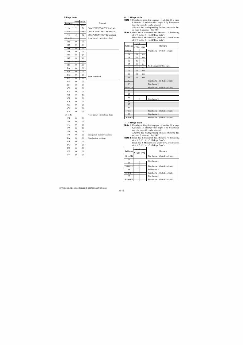
7/18/2019 SONY+HVR-HD1000 SERVICE MANUAL
http://slidepdf.com/reader/full/sonyhvr-hd1000-service-manual 145/4255-34
Ref. No. Part No. Description Ref. No. Part No. Description
HVR-HD1000J/HD1000U/HD1000N/HD1000E/HD1000P/HD1000C
RB5007 1-234-375-21 RES, NETWORK 1K (1005X4)
RB5102 1-234-381-21 RES, NETWORK 100K (1005X4)
RB5103 1-234-375-21 RES, NETWORK 1K (1005X4)
RB5104 1-234-375-21 RES, NETWORK 1K (1005X4)
RB5106 1-234-378-21 RES, NETWORK 10K (1005X4)
RB5107 1-234-375-21 RES, NETWORK 1K (1005X4)RB5109 1-234-375-21 RES, NETWORK 1K (1005X4)
RB5110 1-234-378-21 RES, NETWORK 10K (1005X4)
< VIBRATOR >
* X1701 1-813-854-21 QUARTZ CRYSTAL OSCILLATOR (74.25MHz)
(PAL: HD1000E/HD1000P/HD1000C)
* X1701 1-813-855-21 QUARTZ CRYSTAL OSCILLATOR
(89.010989MHz) (NTSC: HD1000J /HD1000U/HD1000N)
* X1801 1-767-205-81 VIBRATOR, CRYSTAL (20MHz)
X3401 1-781-045-21 VIBRATOR, CRYSTAL (24.576MHz)
* X4401 1-767-205-81 VIBRATOR, CRYSTAL (20MHz)
X5002 1-781-525-11 VIBRATOR, CRYSTAL (32.768kHz)
X5101 1-781-620-21 VIBRATOR, CERAMIC (48MHz)
VC-500Ver. 1.3 2008.12The changed portions fromVer. 1.2 are shown in blue.
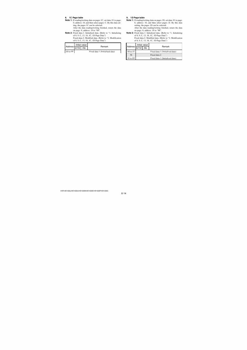
7/18/2019 SONY+HVR-HD1000 SERVICE MANUAL
http://slidepdf.com/reader/full/sonyhvr-hd1000-service-manual 146/4255-35HVR-HD1000J/HD1000U/HD1000N/HD1000E/HD1000P/HD1000C
• Refer to page 5-1 for mark 0.
Note: This item is supplied with the unit as an accessory, but isnot prepared as a service part.
AC AdaptorAC-L1000 1-479-286-21
Power Cord0 1-790-107-42 (US, CND)0 1-575-131-82 (AEP, E)0 1-782-476-51 (CH)
Conversion 2P Adaptor0 1-569-008-12 (E)
Rechargeable Battery PackNP-F570
(Note)
A/V Connecting Cable1-828-145-21
Eye cup3-283-026-01
Lens HoodX-2187-866-1
Lens CapX-2187-867-1
Wind Screen3-283-027-01
Microphone1-542-750-11
CD-ROM(“Manuals for Digital HD VideoCamera Recorder”)
3-279-636-01
Operating Guide3-278-988-11 (ENGLISH) (HD1000U/HD1000N)3-279-638-11 (ENGLISH) (HD1000E/HD1000P)3-279-638-21 (SIMPLIFIED CHINESE) (HD1000C)
3-278-988-11 (ENGLISH)∗ 3-278-988-21 (FRENCH)
3-279-638-11 (ENGLISH)3-279-638-21 (SIMPLIFIED CHINESE)
∗ 3-279-638-31 (FRENCH)∗ 3-279-638-41 (SPANISH)∗ 3-279-638-51 (ITALIAN)∗ 3-279-638-61 (GERMAN)
Operating Guide (PDF)The CD-ROM supplied contains all of language version ofthe Operating Guide (PDF) for printing.• The printed matter is not supplied. If required, please
order it with the part number below.
Ver. 1.2 2008.04
The changed portions fromVer. 1.1 are shown in blue.
to J MODEL
• EXCEPT J MODELChecking supplied accessories.
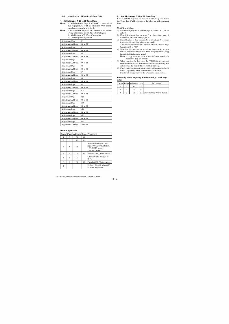
7/18/2019 SONY+HVR-HD1000 SERVICE MANUAL
http://slidepdf.com/reader/full/sonyhvr-hd1000-service-manual 147/4255-36E
HVR-HD1000J/HD1000U/HD1000N/HD1000E/HD1000P/HD1000C
• J MODEL
• 0
0 1-836-251-11
1-823-364-21
3-278-988-01 ()
(PDF)CD-ROMManuals for Digital HDVideo Camera Recorder
3-279-636-04
AC-L1000 1-479-286-32
NP-F570
(Note)
3-283-026-01
X-2187-866-1
X-2187-867-1
3-283-027-01
1-542-750-11
Ver. 1.3 2008.12
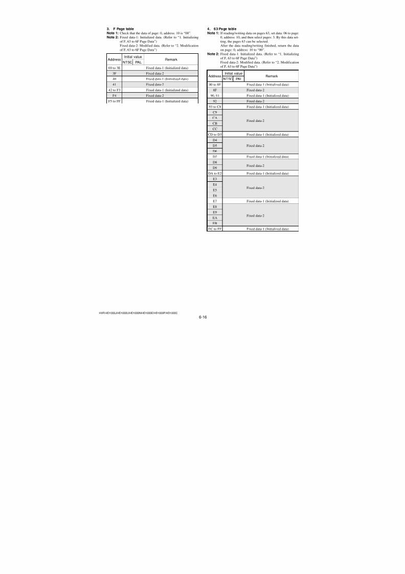
7/18/2019 SONY+HVR-HD1000 SERVICE MANUAL
http://slidepdf.com/reader/full/sonyhvr-hd1000-service-manual 148/425
HVR-HD1000J/HD1000U/HD1000N/HD1000E/HD1000P/HD1000C
Link Link
6. ADJUSTMENTS
Adjusting items when replacing main parts and boards
List of service tools
Before starting adjustments
ELECTRONIC VIEWFINDER SYSTEMADJUSTMENTS
LCD SYSTEM ADJUSTMENTS
CAMERA SYSTEM ADJUSTMENTS
PREPARATIONS BEFORE ADJUSTMENTS
INITIALIZATION OF EVR DATA
CAMERA SECTION ADJUSTMENTS
ADJUSTMENT
PERIODIC INSPECTION AND MAINTENANCE
CHECK, ADJUSTMENT AND REPLACEMENT OFMECHANICAL PARTS
PREPARATIONS FOR CHECK, ADJUSTMENT ANDREPLACEMENT OF MECHANISM BLOCK
MECHANISM SECTION ADJUSTMENTS
AUDIO SYSTEM ADJUSTMENTS
VIDEO SYSTEM ADJUSTMENTS
SERVO AND RF SYSTEM ADJUSTMENTS
SYSTEM CONTROL SYSTEM ADJUSTMENTS
PREPARATIONS BEFORE ADJUSTMENTS
VIDEO SECTION ADJUSTMENTS
SERVICE MODE
DATA PROCESS
ADJUSTMENT REMOTE COMMANDER (RM-95)
SERVICE MODE
ADJUSTMENT REMOTE COMMANDER(NEW LANC JIG)
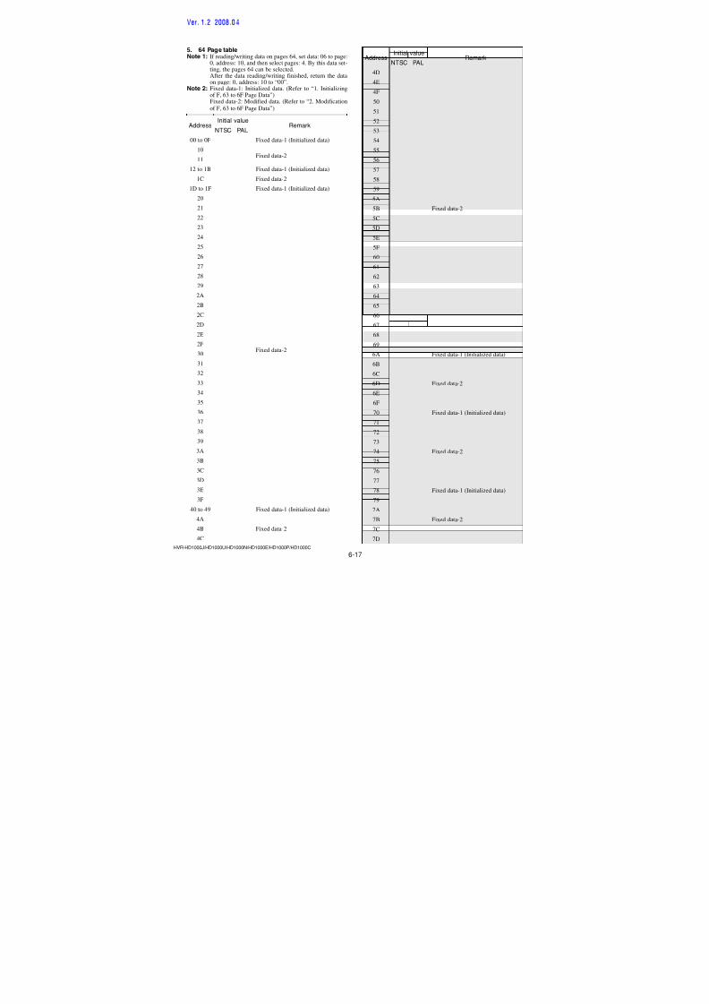
7/18/2019 SONY+HVR-HD1000 SERVICE MANUAL
http://slidepdf.com/reader/full/sonyhvr-hd1000-service-manual 149/4256-1HVR-HD1000J/HD1000U/HD1000N/HD1000E/HD1000P/HD1000C
SECTION 6ADJUSTMENTS
1. Before starting adjustments
EVR Data Re-writing Procedure When Replacing BoardThe data that is stored in the repair board, is not necessarily correct.
Perform either procedure 1 or procedure 2 or procedure 3 when replacing board.
Procedure 1Save the EVR data of the machine in which a board is going to be replaced. Download the saved data after a
board is replaced.
Remove the EEPROM and install it.
(Former board) (New board)
Procedure 2Remove the EEPROM from the board of the machine that is going to be repaired. Install the removed
EEPROM to the replaced board.
Procedure 3When the data cannot be saved due to defective EEPROM, or when the EEPROM cannot be removed or
installed, save the data from the same model of the same destination, and download it.
After the EVR data is saved and downloaded, check therespective items of the EVR data.(Refer to page 6-3 for the items to be checked)
(Machine before starting repair) (Machine after a board is replaced)PC PC
Save the EVR datato a personal computer.
Download the saveddata to a machine.
(Machine to be repaired) (Machine to be repaired)
(The same model of the same destination)
Save the data.
Download the data.
PC
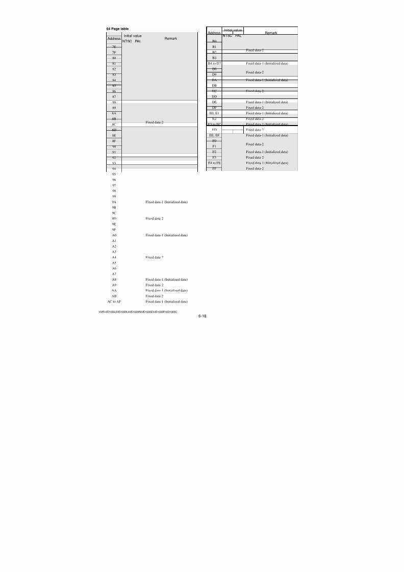
7/18/2019 SONY+HVR-HD1000 SERVICE MANUAL
http://slidepdf.com/reader/full/sonyhvr-hd1000-service-manual 150/4256-2HVR-HD1000J/HD1000U/HD1000N/HD1000E/HD1000P/HD1000C
Table 6-1-1 (1)
1-1. Adjusting items when replacing main parts and boards• Adjusting items when replacing main partsWhen replacing main parts, adjust the items indicated by z in the following table.
Note 1: When replacing the drum assy or the mechanism deck, reset the data of page: 7, address: A8 to AB to “00”. (Refer to “Record of
Use check” of “6-4. SERVICE MODE”)
Replaced part
Block replacement Mounted part replacement
Adjustment Section Adjustment ( L C D p a n e l , T o u c h p a n e l )
( L C D p a n e l )
( D r u m a s s e m b l y ) ( N o t e 1 )
( C l o c k g e n e r a t o r )
( C D S , A / D c o n v e r t e r )
( B a s e b a n d s i g n a l p r o c e s s , e t c . )
( D V s i g n a l p r o c e s s )
( V i d e o o u t )
( C o m p o n e n t o u t A M P )
( R E C / P B A M P )
( E V F d r i v e )
( B a c k l i g h t ( E V F ) )
( L C D d r i v e r )
( B a c k l i g h t ( L C D ) )
L e n s d e v i c e
L C D b l o c k L C D 9
0 1
E V F b l o c k L C D 9
0 2
M e c h a n i s m d e c k
( N o t e 1 )
M e c h a n i s m d e c k
M 9 0 1
M e c h a n i s m d e c k
M D b l o c k
( Y A W , P I T C H s e n s o r )
C M - 0 7 7 b o a r d S E
7 2 0 1 , 7 2 0 2
( C M O S i m a g e r )
C M - 0 7 7 b o a r d I C
6 7 0 1
V C - 5 0 0 b o a r d I C
1 7 0 1 , X 1 7 0 1
V C - 5 0 0 b o a r d I C
1 2 0 1 , 1 3 0 1
V C - 5 0 0 b o a r d I C
2 1 0 1
V C - 5 0 0 b o a r d I C
2 7 0 1
V C - 5 0 0 b o a r d I C
3 0 0 1
V C - 5 0 0 b o a r d I C
2 0 0 1
V C - 5 0 0 b o a r d I C
4 9 0 1
V C - 5 0 0 b o a r d I C
3 7 0 1
B L - 0 1 5 b o a r d D 5
9 0 1
P D - 3 4 2 b o a r d I C 6 2 0 1
P D - 3 4 2 b o a r d D 6
2 0 6 - 6 2 0 8
Initialization of Initialization of A, B, D, 1A, 1B page dataEVR data Initialization of 8, 9, C, 13, 18, 1C, 1D page data
Initialization of F, 63 to 6F page data
Camera Origin oscillation check z
HALL adj. (2)
HALL adj. (1)z
z
MR adj. z
Differential gain adj. z
Flange back adj. z
F No. & ND light quality standard data input z
Mechanical shutter adj. (1)/(2) z
Linear matrix adj. (1)/(2) z
Auto white balance standard data input z
LV standard data input z
Auto white balance adj. z
Color reproduction adj. z
MAX GAIN adj. z
White defect Adj.Black defect Adj. z
z
z
z
z
z
z
z
z
z
z
Angular velocity sensor sensitivity adj. z
EVF EVF automatic adj. z z
White balance adj. z z z
LCD LCD automatic adj. z z
V-COM adj. z
z
z
Transmissive mode white balance adj. z z z
Reflective mode white balance adj. z zSample hold phase adj. z z
Touch panel adj. z
Mechanism Tape path adj. z z z
System control Node uniqe ID No. inputUSB Serial number data setting
Servo, RF CAP FG duty adj. z z
Switching position adj. z z z
Error rate check z z z z z
Video S VIDEO OUT Y level adj. z z
S VIDEO OUT chroma level adj. z z
COMPONENT OUT Y level adj. z z
COMPONENT OUT Pr level adj. z z
COMPONENT OUT Pb level adj. z z
Initialization of 7C, 7E, 7F page data
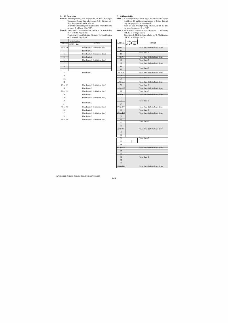
7/18/2019 SONY+HVR-HD1000 SERVICE MANUAL
http://slidepdf.com/reader/full/sonyhvr-hd1000-service-manual 151/4256-3HVR-HD1000J/HD1000U/HD1000N/HD1000E/HD1000P/HD1000C
• Adjusting items when replacing a board or EEPROMWhen replacing a board or EEPROM, adjust the items indicated by z in the following table.
Table 6-1-1 (2)
Replaced part
Adjustment Section Adjustment ( C O M P L E T E )
( C O M P L E T E )
( C O M P L E T E )
( C O M P L E T E )
( E E P R O M )
V C - 5 0 0 b o a r d
C M - 0 7
7 b o a r d
B L - 0 1 5 b o a r d
P D - 3 4 2 b o a r d
V C - 5 0 0 b o a r d I C 1 8 0 2
S u p p o r
t i n g
R a d a r W
Initialization of Initialization of A, B, D, 1A, 1B page data z
EVR data Initialization of 8, 9, C, 13, 18, 1C, 1D page data z
Initialization of F, 63 to 6F page data z z
z z
z z
Camera Origin oscillation check Initialization of 7C, 7E, 7F page data
z
HALL adj. (2) z z z
z
MR adj. z z z
Differential gain adj. z z z
Flange back adj. z z z
F No. & ND light quality standard data input z z z
Mechanical shutter adj. (1)/(2) z z z
Linear matrix adj. (1)/(2) z z z
Auto white balance standard data input z z z
LV standard data input z z z
Auto white balance adj. z z z
Color reproduction adj. z z z
MAX GAIN adj. z z z
White defect Adj. z z z
Black defect Adj. z z z
Angular velocity sensor sensitivity adj.
z
z
z
z
z
z
z
z
z
z z
EVF EVF automatic adj. z z
White balance adj. z z
LCD LCD automatic adj. z z z
V-COM adj. z z
Transmissive mode white balance adj. z z
Reflective mode white balance adj. z z z
Sample hold phase adj. z z
Touch panel adj. z
Mechanism Tape path adj.
System control Node uniqe ID No. inputUSB Serial number data setting z
z
Servo, RF CAP FG duty adj. z z
Switching position adj. z z
Error rate check z z
Video S VIDEO OUT Y level adj. z
S VIDEO OUT chroma level adj. z
COMPONENT OUT Y level adj. z
COMPONENT OUT Pr level adj. z
COMPONENT OUT Pb level adj. z
HALL adj. (1)
R a d a r W
Note 2: When the repair is finished,
confirm the following items.
1. Shoot the all black subject (Attach
the lens cap and shoot), and con-
firm that there is no level differ-ence like vertical stripes in the pic-
ture.
2. Shoot a subject of low light, and
confirm that there is no level dif-
ference like vertical stripes in the
picture.3. Shoot a subject of normal light, and
confirm that there is no level dif-
ference like vertical stripes in the
picture.
When the above symptom occurs,
perform the whole process of
“Differencal Gain Adjustment”.
Note 3: IC2402 (Flash memory) on
the VC-500 board and IC5202
(32M Flash memory) on the
VC-500 board cannot be re-
placed.
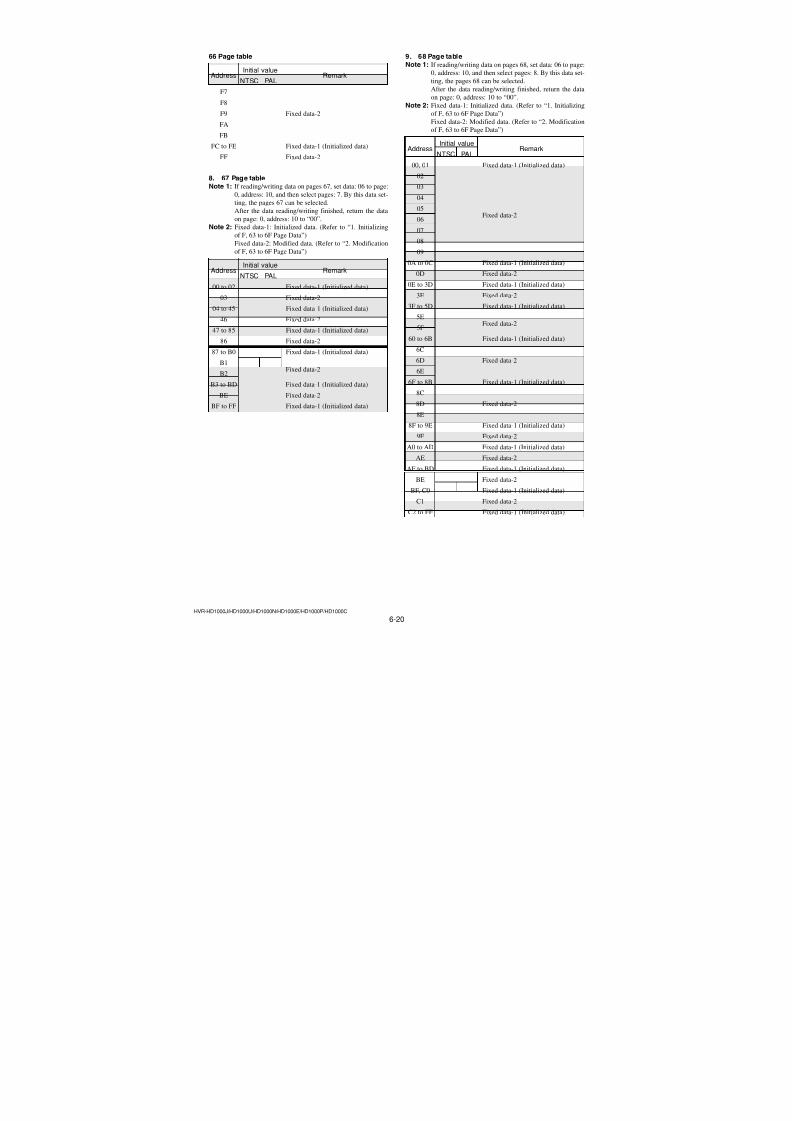
7/18/2019 SONY+HVR-HD1000 SERVICE MANUAL
http://slidepdf.com/reader/full/sonyhvr-hd1000-service-manual 152/4256-4HVR-HD1000J/HD1000U/HD1000N/HD1000E/HD1000P/HD1000C
Fig. 6-1-1 (1)
1-2. List of service tools• Oscilloscope • Color monitor • Vectorscope• Digital voltmeter • Frequency counter • Audio level meter
• Calculating machine capable of calculating hexadecimal numbers
J-13
Tracking standard
(XH2-1)
8-967-997-01
J-14
SW/OL standard
(XH2-3)
8-967-997-11
J-15Audio operation check
for NTSC (XH5-3)
8-967-997-51
for PAL (XH5-3P)
8-967-997-55
J-10
J-9J-7
Pattern box PTB-450
J-6082-200-A
or
Small pattern box
PTB-1450
J-6082-557-A
J-4Color bar chart
For PTB-450:
J-6020-250-A
For PTB-1450:
J-6082-559-A
J-5Clear chart
For PTB-450:
J-6080-621-A
For PTB-1450:
J-6082-560-A
J-6
Minipattern box
J-6082-353-B
Siemens star chart
J-6080-875-A
Filter for color
temperature correction
(C14)
J-6080-058-A
J-11ND filter 1.0
J-6080-808-A
ND filter 0.4
J-6080-806-A
ND filter 0.1
J-6080-807-A
J-8
Flange back
adjustment jig
J-6082-563-A
J-12
Camera table
J-6082-384-A
J-1
Adjustment remote
commander
(RM-95)
J-6082-053-B
J-16
System operation check
for NTSC (XH5-5)
8-967-997-61
for PAL (XH5-5P)
8-967-997-66
AC power adaptor
AC-L100
1-479-286-21
J-18
J-3
LANC cable
J-6082-442-A
J-2
Adjustment remote
commander
(NEW LANC JIG)
J-6082-565-A
J-17
A: CPC-15J-6082-564-A
B: I/F unit forLANC controlJ-6082-521-A
A
B
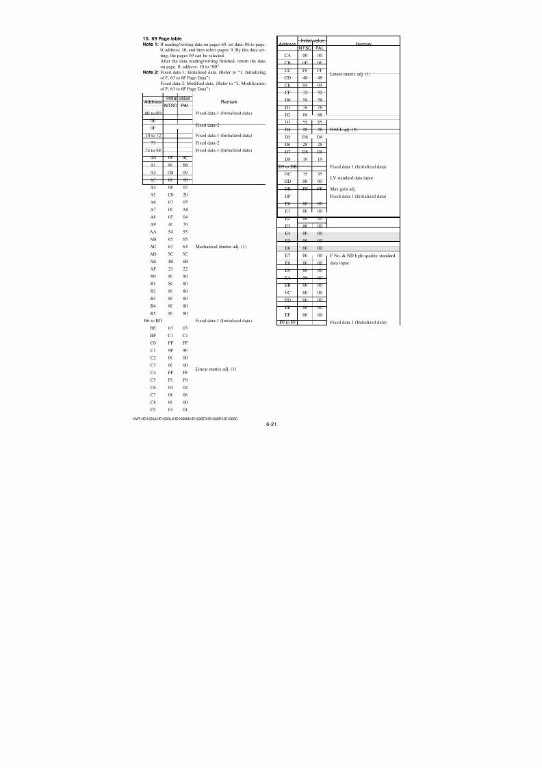
7/18/2019 SONY+HVR-HD1000 SERVICE MANUAL
http://slidepdf.com/reader/full/sonyhvr-hd1000-service-manual 153/4256-5HVR-HD1000J/HD1000U/HD1000N/HD1000E/HD1000P/HD1000C
J-19
Head cleaning liquid9-919-573-01
J-20
Wiping cloth7-741-900-53
J-21
Super-fine applicator(made by Nippon
Applicator (P752D))
J-22
Mirror
(small oval type)
J-6080-840-A
J-23
Mini DV
torque cassette
J-6082-360-A
J-24
FWD/BACK
T adjustment
screwdriver
J-6082-364-A
J-25
Torque screwdriver
J-9049-330-A
J-26
Tape path
screwdriver
J-6082-026-A
J-28
Mode Selector II
J-6082-282-B
J-29
Mode Selector II
conversion board (N)
J-6082-567-A
J-32
Grease
(SUNCALL FG-87HSR)
7-640-006-08
J-30
Mode Selector II
ROM (Note1)
J-6082-314-G Torque Driver Bit (#0)J-6082-661-A
J-31
Fig. 6-1-1 (2)
Note 1: This is the ROM used for upgrading the version of Mode
Selector II to enable it to be used for the N mechanism.
Set the indication to “Z” when using the mode selector
II.
Ver. 1.1 2007.12
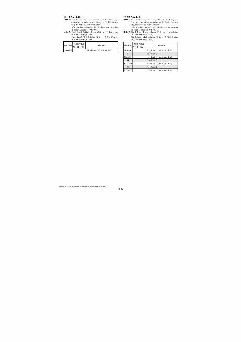
7/18/2019 SONY+HVR-HD1000 SERVICE MANUAL
http://slidepdf.com/reader/full/sonyhvr-hd1000-service-manual 154/4256-6HVR-HD1000J/HD1000U/HD1000N/HD1000E/HD1000P/HD1000C
6-1. CAMERA SECTION ADJUSTMENTS
1-1. PREPARATIONS BEFORE ADJUSTMENTS(CAMERA SECTION)
1-1-1. Preparations
Note: Before perform the adjustment, check that the data of page:0, address: 10 is “00”.
If not, select page: 0, address: 10, and set data “00”.
1) Connect the equipment for adjustments according to Fig. 6-1-
3.
Fig. 6-1-2
Fig. 6-1-3
AC IN
Video(Yellow)
Color monitorVectorscope
Terminated75 Ω
Adjustment remotecommander
(RM-95)
(NEW LANC JIG)
DC IN jack
LANC jack
AC adaptorAC-L100(1-479-286-21)
RM-95(J-6082-053-B)
NEW LANC JIG(J-6082-565-A)LANC cable(J-6082-442-A)
Pattern boxFront of the lens
L = 1 m (PTB-450)L = 40 cm (PTB-1450)
L Camera
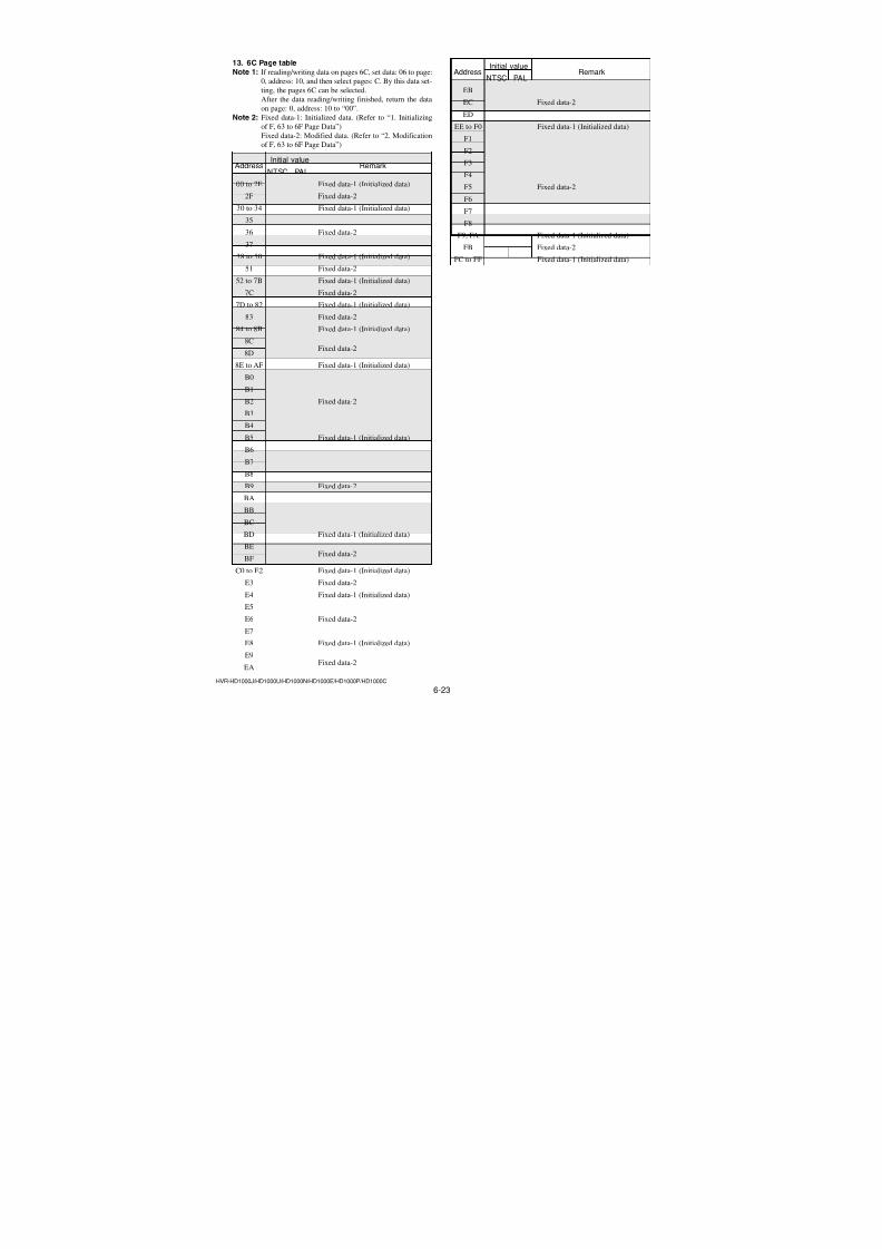
7/18/2019 SONY+HVR-HD1000 SERVICE MANUAL
http://slidepdf.com/reader/full/sonyhvr-hd1000-service-manual 155/4256-7HVR-HD1000J/HD1000U/HD1000N/HD1000E/HD1000P/HD1000C
Fig. b (monitor TV picture)
3. Subjects1) Color bar chart (Color reproduction adjustment frame)
When performing adjustments using the color bar chart, ad-
just the picture frame as shown in Fig. 6-1-4. (Color reproduc-
tion adjustment frame)
2) Clear chart (AWB adjustment frame)
Shoot the color bar chart. Then adjust the zoom to TELE side
from WIDE side, and stop it when the black frame of the chartdisappears. Remove the color bar chart from pattern box and
insert a clear chart in its place.
3) Chart for flange back adjustment
Join together a piece of white A0 size paper (1189 mm × 841
mm) and a piece of black paper to make the chart shown in
Fig. 6-1-5.
Note: Use a non-reflecting and non-glazing vellum paper. The
size must be A0 or larger and the joint between the white
and black paper must not have any undulations.Fig. 6-1-5
Black
White
841 mm
1189 mm
H
A=BA B B A
Enlargement
B A
Difference in level
Y e l l o w
C y a n
G r e e n
W h i t e
M a g e n t a
R e d
B l u e
C = D = 0
V
C D
Y e l l o w
C y a n
B l u e
G r e e n
W h i t e
M a g e n t a
R e d CRT picture frame
Electronic beam scanning frame
Color bar chart (Color reproduction adjustment frame)
Fig. a(VIDEO terminal of A/V jackoutput waveform)
Adjust the camera zoom and direction toobtain the output waveform shown in Fig. a andthe monitor TV display shown in Fig. b.
2. Order of AdjustmentsBasically carry out adjustments in the order given.
Fig. 6-1-4
1-1-2. Precaution1. Setting the SwitchUnless otherwise specified, set the switches as follows and perform adjustments without loading cassette.
1. POWER switch (PS90500 block)................CAMERA-TAPE
2. BACK LIGHT (SP-048 board) ........................................ OFF
3. NIGHT SHOT switch (SP-048 board) ............................ OFF
4. SCENE SELECT (MENU setting) .............................. AUTO5. SPOT METER (MENU setting) ................................... AUTO
6. EXPOSURE (MENU setting) ...................................... AUTO7. WHITE BAL. (MENU setting) .................................... AUTO
8. AE SHIFT (MENU setting)................................................... 0
9. WB SHIFT (MENU setting) ................................................. 0
10. FOCUS (MENU setting) ....................................... MANUAL
11. COLOR SLOW S (MENU setting) ................................. OFF
12. DIGITAL ZOOM (MENU setting) ................................. OFF13. STEADY SHOT (MENU setting) ................................... OFF
14. D. EFFECT (MENU setting) ........................................... OFF15. PICT. EFFECT (MENU setting) ..................................... OFF
16. REC FORMAT (MENU setting) .......................... HDV 1080i

7/18/2019 SONY+HVR-HD1000 SERVICE MANUAL
http://slidepdf.com/reader/full/sonyhvr-hd1000-service-manual 156/4256-8HVR-HD1000J/HD1000U/HD1000N/HD1000E/HD1000P/HD1000C
Initializing method:
Order Page Address Data Procedure
1 0 01 01
2 0 10 00
3 7 04
Set the following data
00: NTSC model01: PAL model
Set the following data
20: Initializing A page21: Initializing B page
22: Initializing D page
23: Initializing 1A page
24: Initializing 1B page4 7 0125: Initializing A and 1A
page
26: Initializing B and 1Bpage
28: Initializing A, B, D, 1A
and 1B page
5 7 02 FF
6 7 00 01 Press PAUSE (Write) button.
7 7 02Check the data changes to
“01”.
8 Perform “Modification of A,
B, D, 1A, 1B Page Data”
1-2. INITIALIZATION OF EVR DATANote 1: Pages used for the EVR consists of 26 pages. There are
8, 9, A to D, F, 13, 18, 1A to 1D, 63 to 6F pages.Note 2: When reading or writing the 13, 18, 1A, 1B, 1C or 1D
page data, select page: 0, address: 10, and set data: 01,
then sclect 3, 8, A, B, C or D page. The 13, 18, 1A, 1B,
1C or 1D page can be chosen by this data setting.
After reading or writing, reset the data or page: 0, ad-dress: 10 to “00”.
Note 3: When reading or writing the 63 to 6F page data, selectpage: 0, address: 10, and set data: 06, then select 3, 4, 5,
6, 7, 8, 9, A, B, C, D, E, or F page. The 63, 64, 65, 66, 67,
68, 69, 6A, 6B, 6C, 6D, 6E, or 6F page can be chosen by
this data setting.
After reading or writing, reste the data of page: 0, ad-
dress: 10 to “00”.
1-3-1. Initialization of A, B, D, 1A, 1B Page DataNote: Check that the data of page: 0, address: 10 is “00”.
1. Initializing of A, B, D, 1A, 1B Page DataNote: If the A, B, D, 1A, 1B page data has been initialized, the
following adjustments need to be performed again.
1) Modification of A, B, D, 1A, 1B page data
2) Touch panel adjustment
Adjustment Page A
Adjustment Address 10 to FF
Adjustment Page B
Adjustment Address 00 to FF
Adjustment Page D
Adjustment Address 10 to FF
Adjustment Page 1A
Adjustment Address 00 to FF
Adjustment Page 1B
Adjustment Address 00 to FF
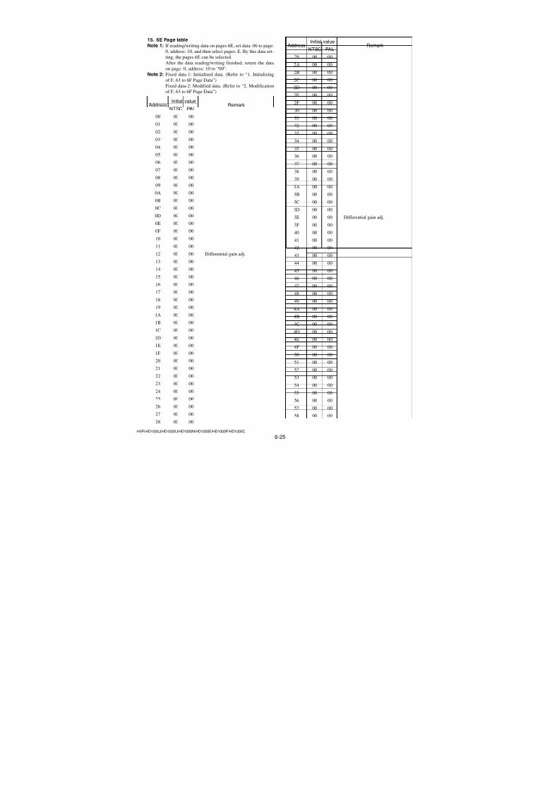
7/18/2019 SONY+HVR-HD1000 SERVICE MANUAL
http://slidepdf.com/reader/full/sonyhvr-hd1000-service-manual 157/4256-9HVR-HD1000J/HD1000U/HD1000N/HD1000E/HD1000P/HD1000C
2. Modification of A, B, D, 1A, 1B Page DataIf the A, B, D, 1A, 1B page data has been initialized, change thedata of the “Fixed data-2” address shown in the following table by
manual input.
Processing before Modification A, B, D, 1A, 1B page data:
Order Page Address Data Procedure1 0 01 01
2 0 10 00
3 7 01 38
4 7 02 FF
5 7 04 02
6 7 00 01 Press PAUSE (Write) button.
7 7 02 Check the data changes to
“01”.
Modifying Method:
1) If modification of data on pages A, B, D, set data: 00 to page:0, address: 10, and then select pages A, B, D.
2) If modification of data on pages 1A, 1B, set data: 01 to page:
0, address: 10, and then select pages A, B.After the modification of data finished, return the data on page:
0, address: 10 to “00”.
3) New data for changing are not shown in the tables because
they are different in destination. When changing the data, copy
the data built in the same model.Note 1: If copy the data built in the different model, the
camcorder may not operate.4) When changing the data, press the PAUSE (Write) button of
the adjustment remote commander each time when setting new
data to write the data in the non-volatile memory.
5) Check that the data of adjustment addresses is the initial value.If not, change the data to the initial value.
Processing after Completing Modification A, B, D, 1A, 1B
page data:
Order Page Address Data Procedure
1 0 10 00
2 7 01 38
3 7 02 FF
4 7 04 01
5 7 00 01 Press PAUSE (Write) button.
6 7 02 Check the data changes to“01”.
7 2 00 29
8 2 01 29 Press PAUSE (Write) button.
Note 2: If following symptoms occur after completing of the
“Modification A, B, D, 1A, 1B page data”, check that
the data of the “Fixed data-2” address of A, B, D, 1A, 1B
page are same as those of same model of same destina-tion.
1) The power is shut off so that unit cannot operate.
3. A Page tableNote 1: Check that the data of page: 0, address: 10 is “00”.Note 2: Fixed data-1: Initialized data. (Refer to “1. Initializing
of A, B, D, 1A, 1B Page Data”)
Fixed data-2: Modified data. (Refer to “2. Modification
of A, B, D, 1A, 1B Page Data”)
Address Initial value RemarkNTSC PAL
10 00 00 Test mode
11 to 5A Fixed data-1 (Initialized data)
5B Fixed data-2
5C, 5D Fixed data-1 (Initialized data)
5E
5F
60 Fixed data-2
61
62
63 to 7B Fixed data-1 (Initialized data)
7C
7D
7EFixed data-2
7F
80 to 8F Fixed data-1 (Initialized data)
90 E8 EA
91 0E 0D
92 DE DDTouch panel adj.
93 19 17
94 to FF Fixed data-1 (Initialized data)
4. B Page tableNote 1: Check that the data of page: 0, address: 10 is “00”.Note 2: Fixed data-1: Initialized data. (Refer to “1. Initializing
of A, B, D, 1A, 1B Page Data”)Fixed data-2: Modified data. (Refer to “2. Modification
of A, B, D, 1A, 1B Page Data”)
AddressInitial value
RemarkNTSC PAL
00 to D0 Fixed data-1 (Initialized data)
D1 00 00
D2 00 00
D3 00 00
D4 00 00
D5 00 00 USB Serial number data setting
D6 00 00
D7 00 00
D8 00 00
D9 00 00
DA to FF Fixed data-1 (Initialized data)
Ver. 1.3 2008.12
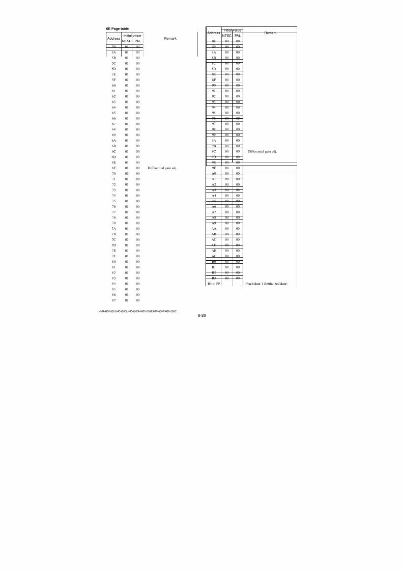
7/18/2019 SONY+HVR-HD1000 SERVICE MANUAL
http://slidepdf.com/reader/full/sonyhvr-hd1000-service-manual 158/4256-10
HVR-HD1000J/HD1000U/HD1000N/HD1000E/HD1000P/HD1000C
5. D Page table
Note 1: Check that the data of page: 0, address: 10 is “00”.
Note 2: Fixed data-1: Initialized data. (Refer to “1. Initializing
of A, B, D, 1A, 1B Page Data”)
Fixed data-2: Modified data. (Refer to “2. Modification
of A, B, D, 1A, 1B Page Data”)
Address Initial value RemarkNTSC PAL
10 to 13 Fixed data-1 (Initialized data)
14
15Fixed data-2
16 to 18 Fixed data-1 (Initialized data)
19 Fixed data-2
1A to 28 Fixed data-1 (Initialized data)
29 Fixed data-2
2A Fixed data-1 (Initialized data)
2B Fixed data-2
2C to 35 Fixed data-1 (Initialized data)
36
37Fixed data-2
38 Fixed data-1 (Initialized data)
39
3A Fixed data-2
3B
3C Fixed data-1 (Initialized data)
3D Fixed data-2
3E to 63 Fixed data-1 (Initialized data)
64
65 Fixed data-2
66
67 to 73 Fixed data-1 (Initialized data)
74 Fixed data-2
75 to 7B Fixed data-1 (Initialized data)
7C Fixed data-2
7D to FF Fixed data-1 (Initialized data)
6. 1A Page table
Note 1: If reading/writing data on pages 1A, set data: 01 to page:
0, address: 10, and then select pages: A. By this data set-
ting, the pages 1A can be selected.
After the data reading/writing finished, return the data
on page: 0, address: 10 to “00”.
Note 2: Fixed data-1: Initialized data. (Refer to “1. Initializing
of A, B, D, 1A, 1B Page Data”)Fixed data-2: Modified data. (Refer to “2. Modification
of A, B, D, 1A, 1B Page Data”)
AddressInitial value
RemarkNTSC PAL
00 to 77 Fixed data-1 (Initialized data)
78
79 Fixed data-2
7A
7B, 7C Fixed data-1 (Initialized data)
7D Fixed data-2
7E Fixed data-1 (Initialized data)
7F Fixed data-2
80 Fixed data-1 (Initialized data)
81 Fixed data-2
82 to FF Fixed data-1 (Initialized data)
7. 1B Page table
Note 1: If reading/writing data on pages 1B, set data: 01 to page:
0, address: 10, and then select pages: B. By this data set-
ting, the pages 1B can be selected.
After the data reading/writing finished, return the data
on page: 0, address: 10 to “00”.
Note 2: Fixed data-1: Initialized data. (Refer to “1. Initializing
of A, B, D, 1A, 1B Page Data”)
Fixed data-2: Modified data. (Refer to “2. Modification
of A, B, D, 1A, 1B Page Data”)
AddressInitial value
RemarkNTSC PAL
00 to FF Fixed data-1 (Initialized data)
Ver. 1.3 2008.12
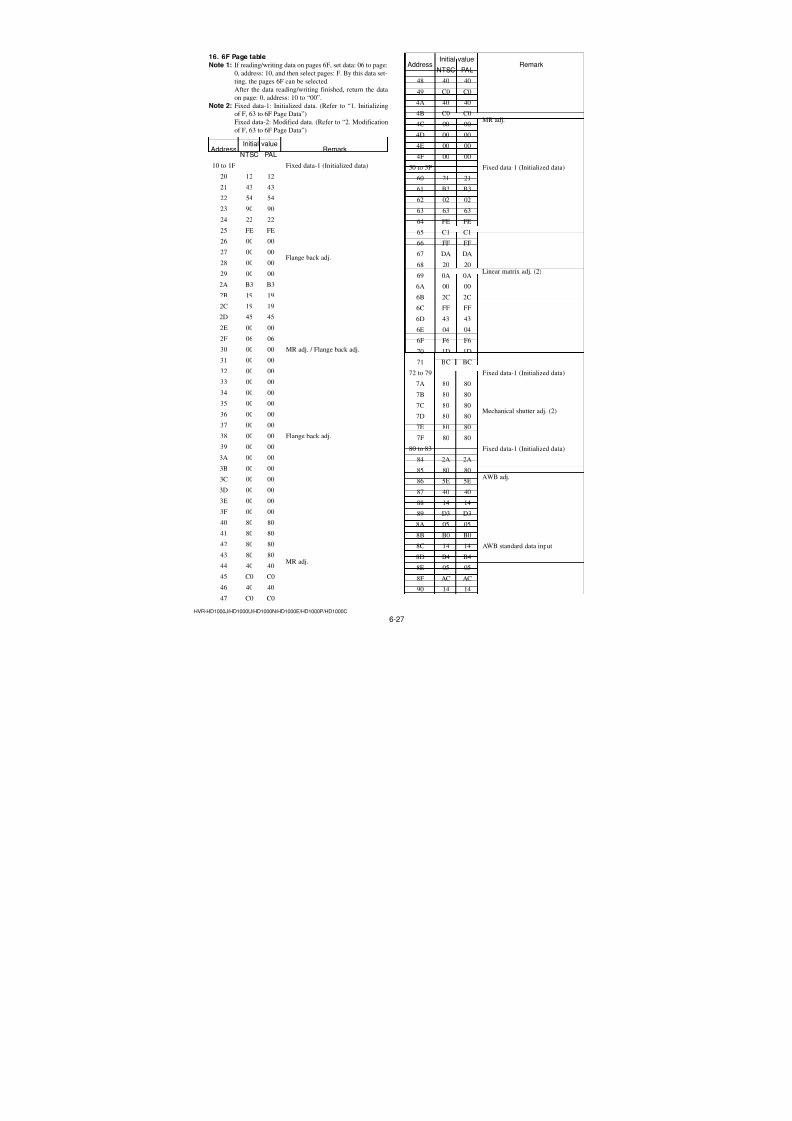
7/18/2019 SONY+HVR-HD1000 SERVICE MANUAL
http://slidepdf.com/reader/full/sonyhvr-hd1000-service-manual 159/4256-11HVR-HD1000J/HD1000U/HD1000N/HD1000E/HD1000P/HD1000C
1-2-2. Initialization of 8, 9, C, 13, 18, 1C, 1D Page Data
1. Initializing of 8, 9, C, 13, 18, 1C, 1D Page DataNote 1: If “Initialization of Pages 8, 9, C, 13, 18, 1C, 1D” is ex-
ecuted, all data on pages 8, 9, C, 13, 18, 1C, 1D are ini-
tialized. (Only an individual page cannot be initialized)
Note 2: If the 8, 9, C, 13, 18, 1C, 1D page data has been initial-
ized, the following adjustments need to be performedagain.1) Modification of 8, 9, C, 13, 18, 1C, 1D page data
2) Electronic viewfinder system adjustments (if all ar-
eas were initialized)
3) LCD system adjustments (if all areas were initial-
ized)
4) Node unique ID No. input (if all areas were initial-
ized)
5) Servo and RF system adjustments (if all areas wereinitialized)
6) Video system adjustments (if all areas were initial-
ized)
Adjustment Page 8Adjustment Address 00 to FF
Adjustment Page 9
Adjustment Address 00 to FF
Adjustment Page C
Adjustment Address 10 to FF
Adjustment Page 13
Adjustment Address 00 to FF
Adjustment Page 18
Adjustment Address 00 to FF
Adjustment Page 1C
Adjustment Address 00 to FF
Adjustment Page 1D
Adjustment Address 00 to FF
Initializing method:
Order Page Address Data Procedure
1 0 01 01
2 0 10 00
Set the following data, andpress PAUSE (Write) button.
(Note 3)
3 3 81 00: Initializing all areas
01: Initializing other than
adjustment address
4 3 80 0C Press PAUSE (Write) button.
Check the data changes to5 3 80“1C”.
6
Perform “Modification of 8,
9, C, 13, 18, 1C, 1D PageData”
Note 3: If other than adjustment address was initialized, the ad-
justed data is not initialized.
2. Modification of 8, 9, C, 13, 18, 1C, 1D Page DataIf the 8, 9, C, 13, 18, 1C, 1D page data has been initialized, changethe data of the “Fixed data-2” address shown in the following table
by manual input.
Processing before Modification 8, 9, C, 13, 18, 1C, 1D
page data:
Order Page Address Data Procedure
1 0 01 01
2 0 10 00
3 3 71 01 Press PAUSE (Write) button.
Modifying Method:
1) If modification of data on pages 8, 9, C, set data: 00 to page: 0,
address: 10, and then select pages 8, 9, C.
2) If modification of data on pages 13, 18, 1C, 1D, set data: 01to page: 0, address: 10, and then select pages 3, 8, C, D.
After the modification of data finished, return the data on page:
0, address: 10 to “00”.
3) New data for changing are not shown in the tables because
they are different in destination. When changing the data, copy
the data built in the same model.Note: If copy the data built in the different model, the
camcorder may not operate.
4) When changing the data, press the PAUSE (Write) button of
the adjustment remote commander each time when setting new
data to write the data in the non-volatile memory.
5) If all areas were initialized, check that the data at the addresses
for adjustment are initial values (adjustment initial values)
listed in the table.If different, change them to the adjustment initial values.
Processing after Completing Modification 8, 9, C, 13, 18, 1C, 1Dpage data:
Order Page Address Data Procedure
1 0 01 01
2 0 10 00
3 3 70 10 Press PAUSE (Write) button.
4 3 70 Check the data changes to
“11”.
5 2 00 29
6 2 01 29 Press PAUSE (Write) button.
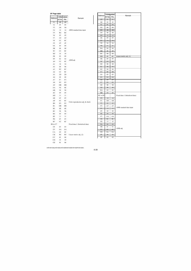
7/18/2019 SONY+HVR-HD1000 SERVICE MANUAL
http://slidepdf.com/reader/full/sonyhvr-hd1000-service-manual 160/4256-12HVR-HD1000J/HD1000U/HD1000N/HD1000E/HD1000P/HD1000C
3. 8 Page tableNote 1: Check that the data of page: 0, address: 10 is “00”.Note 2: Fixed data-1: Initialized data. (Refer to “1. Initializing
of 8, 9, C, 13, 18, 1C, 1D Page Data”)
Fixed data-2: Modified data. (Refer to “2. Modification
of 8, 9, C, 13, 18, 1C, 1D Page Data”)
Address Initial value RemarkNTSC PAL
00 Fixed data-2
01 Fixed data-1 (Initialized data)
02 Fixed data-2
03 to FF Fixed data-1 (Initialized data)
4. 9 Page tableNote 1: Check that the data of page: 0, address: 10 is “00”.
Note 2: Fixed data-1: Initialized data. (Refer to “1. Initializing
of 8, 9, C, 13, 18, 1C, 1D Page Data”)
Fixed data-2: Modified data. (Refer to “2. Modification
of 8, 9, C, 13, 18, 1C, 1D Page Data”)
AddressInitial value
RemarkNTSC PAL
00 to FF Fixed data-1 (Initialized data)
5. C Page tableNote 1: Check that the data of page: 0, address: 10 is “00”.Note 2: Fixed data-1: Initialized data. (Refer to “1. Initializing
of 8, 9, C, 13, 18, 1C, 1D Page Data”)
Fixed data-2: Modified data. (Refer to “2. Modification
of 8, 9, C, 13, 18, 1C, 1D Page Data”)
Address Initial value RemarkNTSC PAL
10 EE EE
11 00 00Switching position adj.
12 00 00
13 00 00
14, 15 Fixed data-1 (Initialized data)
16 E0 E0 CAP FG duty adj.
17 to 24 Fixed data-1 (Initialized data)
25 70 -S VIDEO OUT Y level adj. (NTSC)/
Fixed data-1 (PAL)
26 8A - S VIDEO OUT chroma level adj. (NTSC)/
27 61 - Fixed data-1 (PAL)
28 to 30 Fixed data-1 (Initialized data)
31 Fixed data-2
32, 33 Fixed data-1 (Initialized data)
34 80 80VCO adj. (EVF)
35 8A 8A
36 to 39 Fixed data-1 (Initialized data)
3A 93 93White balance adj. (EVF)
3B 7F 7F
3C 82 82 Contrast adj. (EVF)
3D to 41 Fixed data-1 (Initialized data)
42 Fixed data-2
43, 44 Fixed data-1 (Initialized data)
45 64 64VCO adj. (LCD)
46 6E 6E
47 95 95 V-COM adj. (LCD)
48 to 4A Fixed data-1 (Initialized data)
4B 8A 8A Transmissive mode white balance
4C 64 64 adj. (LCD)
4D 7A 7A Contrast adj. (LCD)4E to 53 Fixed data-1 (Initialized data)
54 3F 3F Sample hold phase adj.
55 to 6F Fixed data-1 (Initialized data)
70 72 72 Reflective mode white balance
71 6A 6A adj. (LCD)
72 to 75 Fixed data-1 (Initialized data)
76 7A 7A Contrast adj. (LCD)
77 82 82 Contrast adj. (EVF)
78 to 84 Fixed data-1 (Initialized data)
85 - 70Fixed data-1 (NTSC)/
S VIDEO OUT Y level adj. (PAL)
86 - 8A Fixed data-1 (NTSC)/
87 - 61 S VIDEO OUT chroma level adj. (PAL)
88 to 92 Fixed data-1 (Initialized data)
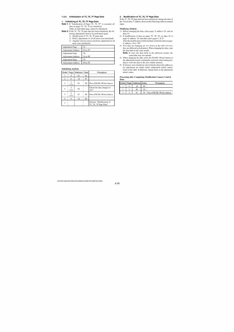
7/18/2019 SONY+HVR-HD1000 SERVICE MANUAL
http://slidepdf.com/reader/full/sonyhvr-hd1000-service-manual 161/4256-13HVR-HD1000J/HD1000U/HD1000N/HD1000E/HD1000P/HD1000C
C Page table
AddressInitial value
RemarkNTSC PAL
93 79 79 COMPONENT OUT Y level adj.
94 31 31 COMPONENT OUT Pb level adj.
95 32 32 COMPONENT OUT Pr level adj.
96 to B1 Fixed data-1 (Initialized data)
B2 00 00
B3 00 00
B4 00 00
B5 00 00
B6 00 00
B7 80 80
B8 00 00
B9 00 00
BA 00 00BB 00 00
BC 00 00
BD 00 00Error rate check
BE 00 00
BF 00 00
C0 00 00
C1 00 00
C2 80 80
C3 00 00
C4 00 00
C5 00 00
C6 00 00
C7 00 00
C8 to F3 Fixed data-1 (Initialized data)
F4 00 00
F5 00 00
F6 00 00
F7 00 00
F8 00 00
F9 00 00 Emergency memory address
FA 00 00 (Mechanism section)
FB 00 00
FC 00 00
FD 00 00
FE 00 00
FF 00 00
6. 13 Page tableNote 1: If reading/writing data on pages 13, set data: 01 to page:
0, address: 10, and then select pages: 3. By this data set-
ting, the pages 13 can be selected.
After the data reading/writing finished, return the data
on page: 0, address: 10 to “00”.
Note 2: Fixed data-1: Initialized data. (Refer to “1. Initializing
of 8, 9, C, 13, 18, 1C, 1D Page Data”)Fixed data-2: Modified data. (Refer to “2. Modificationof 8, 9, C, 13, 18, 1C, 1D Page Data”)
AddressInitial value
RemarkNTSC PAL
00 to 03 Fixed data-1 (Initialized data)
04 08 08
05 00 00
06 46 46
07 01 01
08 02 02Node unique ID No. input
09 00 00
0A 00 00
0B 00 00
0C Fixed data-1 (Initialized data)
0D Fixed data-2
0E to 10 Fixed data-1 (Initialized data)
11
12
13
14Fixed data-2
15
16
17 to 24 Fixed data-1 (Initialized data)
25 Fixed data-2
26 to FF Fixed data-1 (Initialized data)
7. 18 Page tableNote 1: If reading/writing data on pages 18, set data: 01 to page:
0, address: 10, and then select pages: 8. By this data set-
ting, the pages 18 can be selected.
After the data reading/writing finished, return the data
on page: 0, address: 10 to “00”.
Note 2: Fixed data-1: Initialized data. (Refer to “1. Initializingof 8, 9, C, 13, 18, 1C, 1D Page Data”)
Fixed data-2: Modified data. (Refer to “2. Modificationof 8, 9, C, 13, 18, 1C, 1D Page Data”)
AddressInitial value
RemarkNTSC PAL
00 to 2D Fixed data-1 (Initialized data)
2E
2FFixed data-2
30 to 33 Fixed data-1 (Initialized data)
34 Fixed data-2
35 to F1 Fixed data-1 (Initialized data)
F2 Fixed data-2
F3 to FF Fixed data-1 (Initialized data)
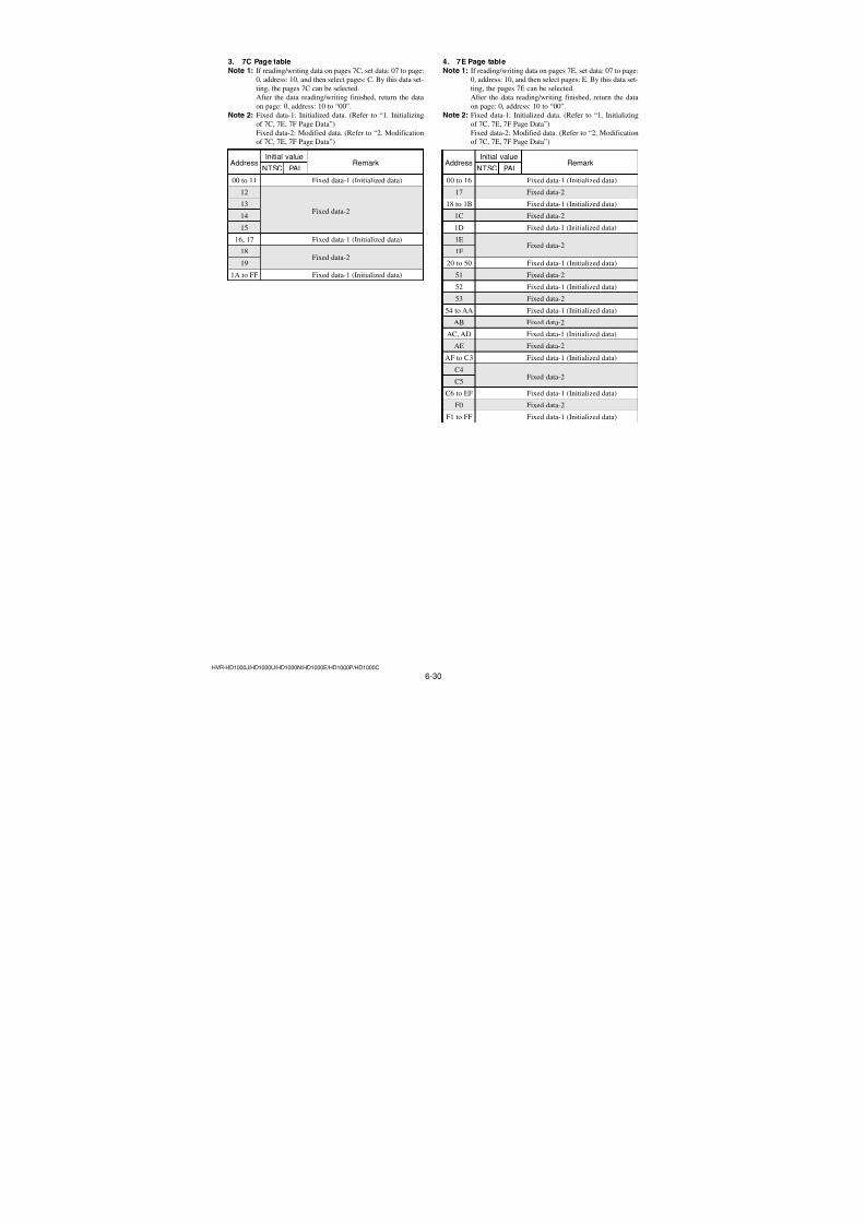
7/18/2019 SONY+HVR-HD1000 SERVICE MANUAL
http://slidepdf.com/reader/full/sonyhvr-hd1000-service-manual 162/4256-14HVR-HD1000J/HD1000U/HD1000N/HD1000E/HD1000P/HD1000C
8. 1C Page tableNote 1: If reading/writing data on pages 1C, set data: 01 to page:
0, address: 10, and then select pages: C. By this data set-
ting, the pages 1C can be selected.
After the data reading/writing finished, return the data
on page: 0, address: 10 to “00”.
Note 2: Fixed data-1: Initialized data. (Refer to “1. Initializing
of 8, 9, C, 13, 18, 1C, 1D Page Data”)Fixed data-2: Modified data. (Refer to “2. Modificationof 8, 9, C, 13, 18, 1C, 1D Page Data”)
AddressInitial value
RemarkNTSC PAL
00 to FF Fixed data-1 (Initialized data)
9. 1D Page tableNote 1: If reading/writing data on pages 1D, set data: 01 to page:
0, address: 10, and then select pages: D. By this data
setting, the pages 1D can be selected.
After the data reading/writing finished, return the data
on page: 0, address: 10 to “00”.
Note 2: Fixed data-1: Initialized data. (Refer to “1. Initializing
of 8, 9, C, 13, 18, 1C, 1D Page Data”)Fixed data-2: Modified data. (Refer to “2. Modification
of 8, 9, C, 13, 18, 1C, 1D Page Data”)
AddressInitial value
RemarkNTSC PAL
00 to 57 Fixed data-1 (Initialized data)
58 Fixed data-2
59 to FF Fixed data-1 (Initialized data)
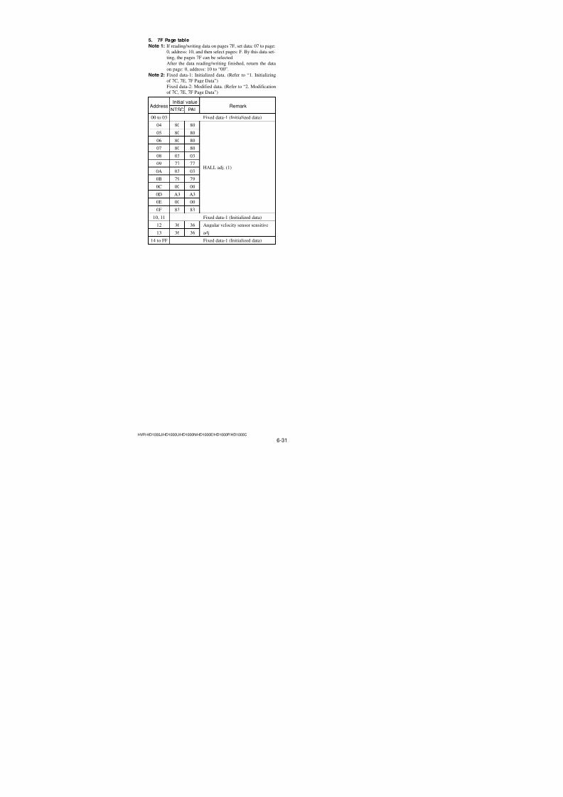
7/18/2019 SONY+HVR-HD1000 SERVICE MANUAL
http://slidepdf.com/reader/full/sonyhvr-hd1000-service-manual 163/4256-15HVR-HD1000J/HD1000U/HD1000N/HD1000E/HD1000P/HD1000C
1-2-3. Initialization of F, 63 to 6F Page Data
1. Initializing of F, 63 to 6F Page DataNote 1: If “Initialization of Pages F, 63 to 6F” is executed, all
data on pages F, 63 to 6F are initialized. (Only an indi-
vidual page cannot be initialized)
Note 2: If the F, 63 to 6F page data has been initialized, the fol-
lowing adjustments need to be performed again.1) Modification of F, 63 to 6F page data2) Camera system adjustment
Adjustment Page F
Adjustment Address 00 to FF
Adjustment Page 63
Adjustment Address 00 to FF
Adjustment Page 64
Adjustment Address 00 to FF
Adjustment Page 65
Adjustment Address 00 to FF
Adjustment Page 66
Adjustment Address 00 to FF
Adjustment Page 67
Adjustment Address 00 to FF
Adjustment Page 68
Adjustment Address 00 to FF
Adjustment Page 69
Adjustment Address 00 to FF
Adjustment Page 6A
Adjustment Address 00 to FF
Adjustment Page 6BAdjustment Address 00 to FF
Adjustment Page 6C
Adjustment Address 00 to FF
Adjustment Page 6D
Adjustment Address 00 to FF
Adjustment Page 6E
Adjustment Address 00 to FF
Adjustment Page 6F
Adjustment Address 10 to FF
Initializing method:
Order Page Address Data Procedure
1 0 01 01
2 0 10 00
3 6 01
Set the following data, and
press PAUSE (Write) button.
2D: NTSC model
2F: PAL model
4 6 03 01 Press PAUSE (Write) button.
5 6 02Check the data changes to
“01”.
6 6 01 00 Press PAUSE (Write) button.
7 Perform “Modification of F,
63 to 6F Page Data”
2. Modification of F, 63 to 6F Page DataIf the F, 63 to 6F page data has been initialized, change the data of the “Fixed data-2” address shown in the following table by manual
input.
Modifying Method:
1) Before changing the data, select page: 0, address: 01, and set
data: 01.2) If modification of data on pages F, set data: 00 to page: 0,
address: 10, and then select pages F.
3) If modification of data on pages 63 to 6F, set data: 06 to page:
0, address: 10, and then select pages 3 to F.
After the modification of data finished, return the data on page:
0, address: 10 to “00”.
4) New data for changing are not shown in the tables because
they are different in destination. When changing the data, copythe data built in the same model.
Note: If copy the data built in the different model, the
camcorder may not operate.
5) When changing the data, press the PAUSE (Write) button of
the adjustment remote commander each time when setting new
data to write the data in the non-volatile memory.
6) Check that the data at the addresses for adjustment are initial
values (adjustment initial values) listed in the table.If different, change them to the adjustment initial values.
Processing after Completing Modification F, 63 to 6F page
data:
Order Page Address Data Procedure
1 0 10 00
2 2 00 29
3 2 01 29 Press PAUSE (Write) button.
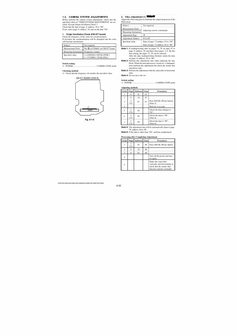
7/18/2019 SONY+HVR-HD1000 SERVICE MANUAL
http://slidepdf.com/reader/full/sonyhvr-hd1000-service-manual 164/4256-16HVR-HD1000J/HD1000U/HD1000N/HD1000E/HD1000P/HD1000C
3. F Page tableNote 1: Check that the data of page: 0, address: 10 is “00”.Note 2: Fixed data-1: Initialized data. (Refer to “1. Initializing
of F, 63 to 6F Page Data”)
Fixed data-2: Modified data. (Refer to “2. Modification
of F, 63 to 6F Page Data”)
Address Initial value RemarkNTSC PAL
00 to 3E Fixed data-1 (Initialized data)
3F Fixed data-2
40 Fixed data-1 (Initialized data)
41 Fixed data-2
42 to F3 Fixed data-1 (Initialized data)
F4 Fixed data-2
F5 to FF Fixed data-1 (Initialized data)
4. 63 Page tableNote 1: If reading/writing data on pages 63, set data: 06 to page:
0, address: 10, and then select pages: 3. By this data set-
ting, the pages 63 can be selected.
After the data reading/writing finished, return the data
on page: 0, address: 10 to “00”.
Note 2: Fixed data-1: Initialized data. (Refer to “1. Initializing
of F, 63 to 6F Page Data”)Fixed data-2: Modified data. (Refer to “2. Modificationof F, 63 to 6F Page Data”)
AddressInitial value
RemarkNTSC PAL
00 to 8E Fixed data-1 (Initialized data)
8F Fixed data-2
90, 91 Fixed data-1 (Initialized data)
92 Fixed data-2
93 to C8 Fixed data-1 (Initialized data)
C9
CA
CBFixed data-2
CC
CD to D3 Fixed data-1 (Initialized data)
D4
D5 Fixed data-2
D6
D7 Fixed data-1 (Initialized data)
D8
D9Fixed data-2
DA to E2 Fixed data-1 (Initialized data)
E3
E4
E5Fixed data-2
E6
E7 Fixed data-1 (Initialized data)
E8
E9
EAFixed data-2
EB
EC to FF Fixed data-1 (Initialized data)
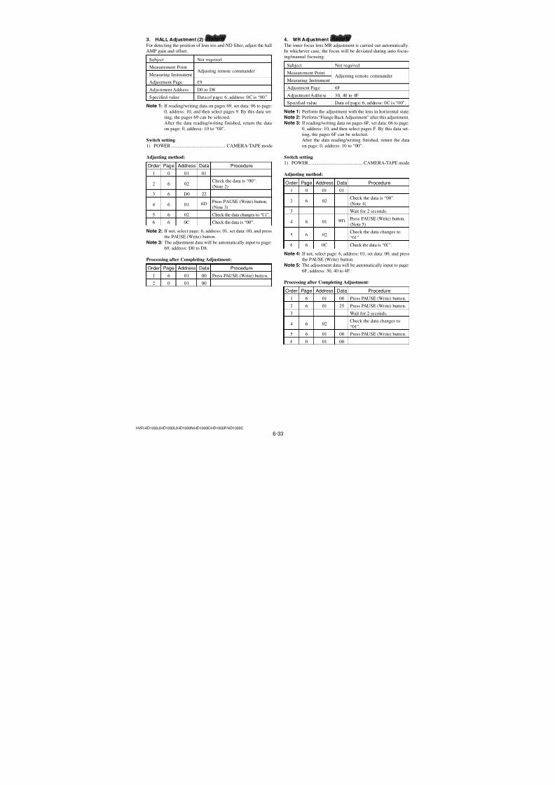
7/18/2019 SONY+HVR-HD1000 SERVICE MANUAL
http://slidepdf.com/reader/full/sonyhvr-hd1000-service-manual 165/4256-17HVR-HD1000J/HD1000U/HD1000N/HD1000E/HD1000P/HD1000C
AddressInitial value
RemarkNTSC PAL
4D
4E
4F
50
51
52
53
54
55
56
57
58
59
5A5B Fixed data-2
5C
5D
5E
5F
60
61
62
63
64
65
66
67
68
69
6A Fixed data-1 (Initialized data)
6B
6C
6D Fixed data-2
6E
6F
70 Fixed data-1 (Initialized data)
71
72
73
74 Fixed data-2
75
76
77
78 Fixed data-1 (Initialized data)
797A
7B Fixed data-2
7C
7D
5. 64 Page tableNote 1: If reading/writing data on pages 64, set data: 06 to page:
0, address: 10, and then select pages: 4. By this data set-ting, the pages 64 can be selected.After the data reading/writing finished, return the dataon page: 0, address: 10 to “00”.
Note 2: Fixed data-1: Initialized data. (Refer to “1. Initializingof F, 63 to 6F Page Data”)
Fixed data-2: Modified data. (Refer to “2. Modificationof F, 63 to 6F Page Data”)
AddressInitial value
RemarkNTSC PAL
00 to 0F Fixed data-1 (Initialized data)
10
11Fixed data-2
12 to 1B Fixed data-1 (Initialized data)
1C Fixed data-2
1D to 1F Fixed data-1 (Initialized data)
2021
22
23
24
25
26
27
28
29
2A
2B
2C
2D
2E
2F
30Fixed data-2
31
32
33
34
35
36
37
38
39
3A
3B
3C
3D
3E
3F40 to 49 Fixed data-1 (Initialized data)
4A
4B Fixed data-2
4C
Ver. 1.2 2008.04
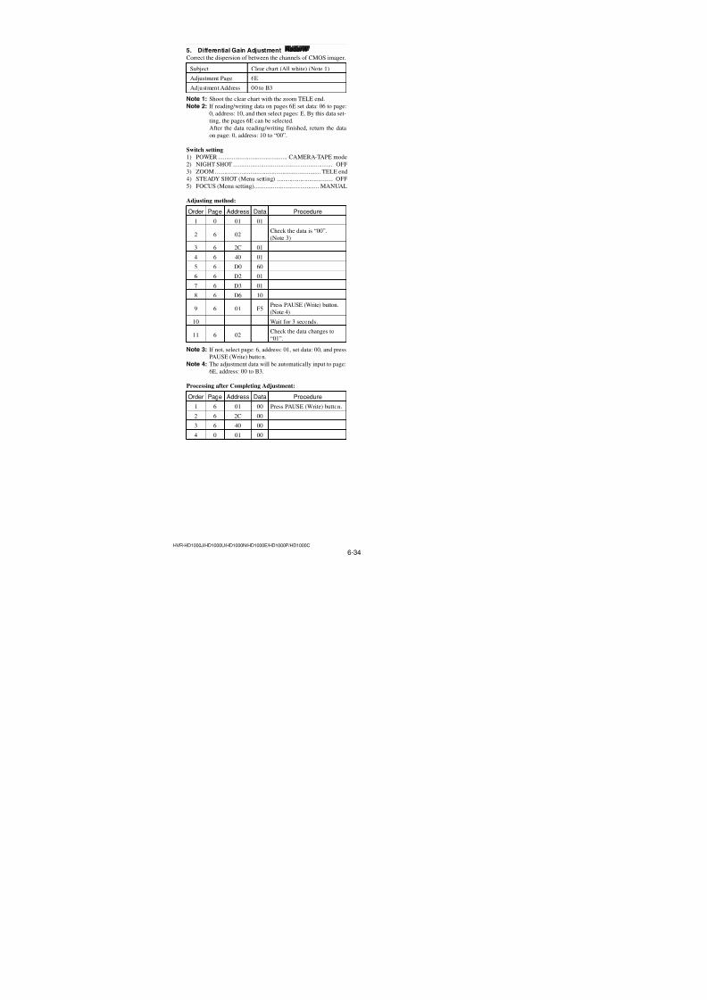
7/18/2019 SONY+HVR-HD1000 SERVICE MANUAL
http://slidepdf.com/reader/full/sonyhvr-hd1000-service-manual 166/4256-18HVR-HD1000J/HD1000U/HD1000N/HD1000E/HD1000P/HD1000C
64 Page table
AddressInitial value
RemarkNTSC PAL
7E
7F
80
81
82
83
84
85
86
87
88
89
8A8B
8CFixed data-2
8D
8E
8F
90
91
92
93
94
95
96
97
98
99
9A Fixed data-1 (Initialized data)
9B
9C
9D Fixed data-2
9E
9F
A0 Fixed data-1 (Initialized data)
A1
A2
A3
A4 Fixed data-2
A5
A6
A7
A8 Fixed data-1 (Initialized data)
A9 Fixed data-2AA Fixed data-1 (Initialized data)
AB Fixed data-2
AC to AF Fixed data-1 (Initialized data)
AddressInitial value
RemarkNTSC PAL
B0
B1
B2Fixed data-2
B3
B4 to D7 Fixed data-1 (Initialized data)
D8
D9Fixed data-2
DA Fixed data-1 (Initialized data)
DB
DC Fixed data-2
DD
DE Fixed data-1 (Initialized data)
DF Fixed data-2
E0, E1 Fixed data-1 (Initialized data)E2 Fixed data-2
E3 to EC Fixed data-1 (Initialized data)
ED Fixed data-2
EE, EF Fixed data-1 (Initialized data)
F0
F1Fixed data-2
F2 Fixed data-1 (Initialized data)
F3 Fixed data-2
F4 to FE Fixed data-1 (Initialized data)
FF Fixed data-2
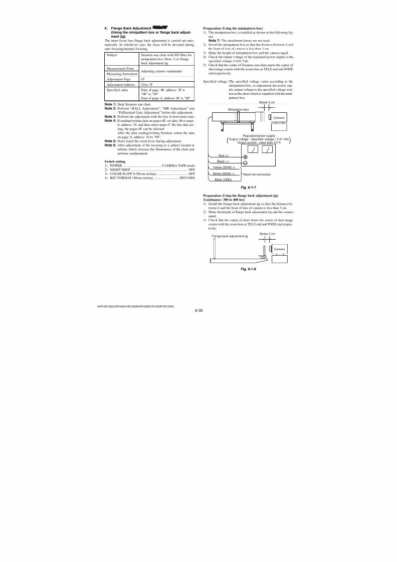
7/18/2019 SONY+HVR-HD1000 SERVICE MANUAL
http://slidepdf.com/reader/full/sonyhvr-hd1000-service-manual 167/4256-19HVR-HD1000J/HD1000U/HD1000N/HD1000E/HD1000P/HD1000C
6. 65 Page tableNote 1: If reading/writing data on pages 65, set data: 06 to page:
0, address: 10, and then select pages: 5. By this data set-
ting, the pages 65 can be selected.
After the data reading/writing finished, return the data
on page: 0, address: 10 to “00”.
Note 2: Fixed data-1: Initialized data. (Refer to “1. Initializing
of F, 63 to 6F Page Data”)Fixed data-2: Modified data. (Refer to “2. Modificationof F, 63 to 6F Page Data”)
AddressInitial value
RemarkNTSC PAL
00 to 10 Fixed data-1 (Initialized data)
11 Fixed data-2
12 Fixed data-1 (Initialized data)
13 Fixed data-2
14 Fixed data-1 (Initialized data)
15
16
17
18 Fixed data-2
19
1A
1B
1C to 1E Fixed data-1 (Initialized data)
1F Fixed data-2
20 to 2D Fixed data-1 (Initialized data)
2E Fixed data-2
2F Fixed data-1 (Initialized data)
30
31Fixed data-2
32 to 35 Fixed data-1 (Initialized data)
36 Fixed data-2
37 Fixed data-1 (Initialized data)
38 Fixed data-2
39 to FF Fixed data-1 (Initialized data)
7. 66 Page tableNote 1: If reading/writing data on pages 66, set data: 06 to page:
0, address: 10, and then select pages: 6. By this data set-
ting, the pages 66 can be selected.
After the data reading/writing finished, return the data
on page: 0, address: 10 to “00”.
Note 2: Fixed data-1: Initialized data. (Refer to “1. Initializing
of F, 63 to 6F Page Data”)Fixed data-2: Modified data. (Refer to “2. Modificationof F, 63 to 6F Page Data”)
AddressInitial value
RemarkNTSC PAL
00 to 11 Fixed data-1 (Initialized data)
12
13Fixed data-2
14 to 97 Fixed data-1 (Initialized data)
98 Fixed data-2
99 Fixed data-1 (Initialized data)
9A
9BFixed data-2
9C, 9D Fixed data-1 (Initialized data)
9E
9FFixed data-2
A0 to A6 Fixed data-1 (Initialized data)
A7 Fixed data-2
A8 to AE Fixed data-1 (Initialized data)
AF Fixed data-2
B0 to C1 Fixed data-1 (Initialized data)
C2
C3 Fixed data-2
C4
C5 to C7 Fixed data-1 (Initialized data)
C8 Fixed data-2
C9 to DF Fixed data-1 (Initialized data)
E0
E1
E2Fixed data-2
E3
E4 to E6 Fixed data-1 (Initialized data)E7
E8
E9 Fixed data-2
EA
EB
EC to EE Fixed data-1 (Initialized data)
EF
F0
F1 Fixed data-2
F2
F3
F4 to F6 Fixed data-1 (Initialized data)
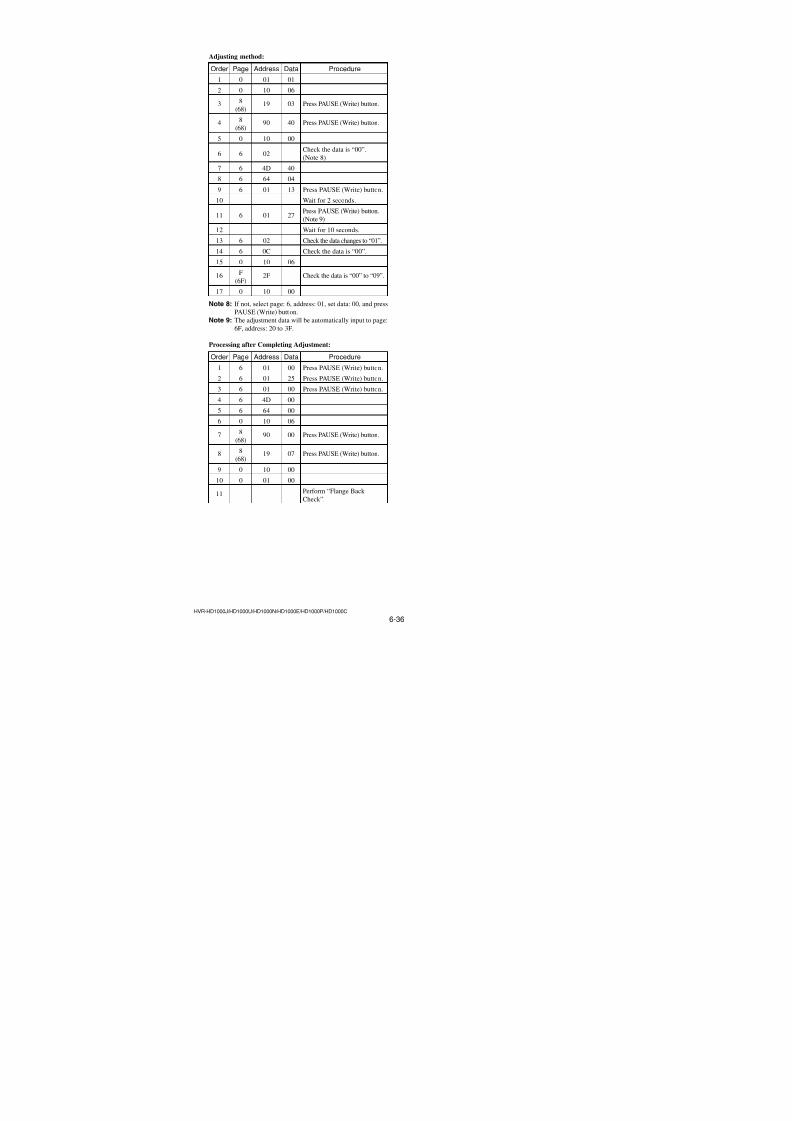
7/18/2019 SONY+HVR-HD1000 SERVICE MANUAL
http://slidepdf.com/reader/full/sonyhvr-hd1000-service-manual 168/4256-20HVR-HD1000J/HD1000U/HD1000N/HD1000E/HD1000P/HD1000C
66 Page table
AddressInitial value
RemarkNTSC PAL
F7
F8
F9 Fixed data-2
FA
FB
FC to FE Fixed data-1 (Initialized data)
FF Fixed data-2
8. 67 Page tableNote 1: If reading/writing data on pages 67, set data: 06 to page:
0, address: 10, and then select pages: 7. By this data set-
ting, the pages 67 can be selected.
After the data reading/writing finished, return the dataon page: 0, address: 10 to “00”.
Note 2: Fixed data-1: Initialized data. (Refer to “1. Initializing
of F, 63 to 6F Page Data”)
Fixed data-2: Modified data. (Refer to “2. Modification
of F, 63 to 6F Page Data”)
AddressInitial value
RemarkNTSC PAL
00 to 02 Fixed data-1 (Initialized data)
03 Fixed data-2
04 to 45 Fixed data-1 (Initialized data)
46 Fixed data-2
47 to 85 Fixed data-1 (Initialized data)
86 Fixed data-2
87 to B0 Fixed data-1 (Initialized data)
B1
B2Fixed data-2
B3 to BD Fixed data-1 (Initialized data)
BE Fixed data-2
BF to FF Fixed data-1 (Initialized data)
9. 68 Page tableNote 1: If reading/writing data on pages 68, set data: 06 to page:
0, address: 10, and then select pages: 8. By this data set-
ting, the pages 68 can be selected.
After the data reading/writing finished, return the data
on page: 0, address: 10 to “00”.
Note 2: Fixed data-1: Initialized data. (Refer to “1. Initializing
of F, 63 to 6F Page Data”)Fixed data-2: Modified data. (Refer to “2. Modificationof F, 63 to 6F Page Data”)
AddressInitial value
RemarkNTSC PAL
00, 01 Fixed data-1 (Initialized data)
02
03
04
05
06Fixed data-2
07
08
09
0A to 0C Fixed data-1 (Initialized data)
0D Fixed data-2
0E to 3D Fixed data-1 (Initialized data)
3E Fixed data-2
3F to 5D Fixed data-1 (Initialized data)
5E
5FFixed data-2
60 to 6B Fixed data-1 (Initialized data)
6C
6D Fixed data-2
6E
6F to 8B Fixed data-1 (Initialized data)
8C
8D Fixed data-2
8E
8F to 9E Fixed data-1 (Initialized data)
9F Fixed data-2
A0 to AD Fixed data-1 (Initialized data)AE Fixed data-2
AF to BD Fixed data-1 (Initialized data)
BE Fixed data-2
BF, C0 Fixed data-1 (Initialized data)
C1 Fixed data-2
C2 to FF Fixed data-1 (Initialized data)
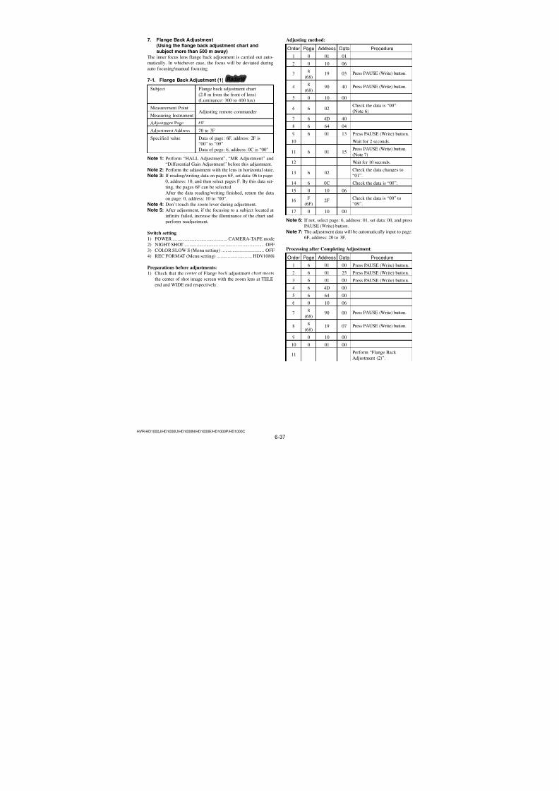
7/18/2019 SONY+HVR-HD1000 SERVICE MANUAL
http://slidepdf.com/reader/full/sonyhvr-hd1000-service-manual 169/4256-21HVR-HD1000J/HD1000U/HD1000N/HD1000E/HD1000P/HD1000C
10. 69 Page tableNote 1: If reading/writing data on pages 69, set data: 06 to page:
0, address: 10, and then select pages: 9. By this data set-
ting, the pages 69 can be selected.
After the data reading/writing finished, return the data
on page: 0, address: 10 to “00”.
Note 2: Fixed data-1: Initialized data. (Refer to “1. Initializing
of F, 63 to 6F Page Data”)Fixed data-2: Modified data. (Refer to “2. Modificationof F, 63 to 6F Page Data”)
AddressInitial value
RemarkNTSC PAL
00 to 0D Fixed data-1 (Initialized data)
0E
0FFixed data-2
10 to 72 Fixed data-1 (Initialized data)
73 Fixed data-2
74 to 9F Fixed data-1 (Initialized data)
A0 0F 0C
A1 80 B0
A2 0B 09
A3 00 10
A4 08 07
A5 C0 20
A6 07 05
A7 00 A0
A8 05 04
A9 40 70
AA 54 55
AB 65 65
AC 63 64 Mechanical shutter adj. (1)
AD 5C 5C
AE 4B 4B
AF 21 22
B0 80 80
B1 80 80
B2 80 80
B3 80 80
B4 80 80B5 80 80
B6 to BD Fixed data-1 (Initialized data)
BE 03 03
BF C1 C1
C0 FF FF
C1 9F 9F
C2 00 00
C3 00 00
C4 FF FFLinear matrix adj. (1)
C5 F9 F9
C6 04 04
C7 06 06
C8 00 00
C9 01 01
AddressInitial value
RemarkNTSC PAL
CA 00 00
CB 0E 0E
CC FF FF
CD 48 48Linear matrix adj. (1)
CE 04 04
CF 32 32
D0 58 58
D1 76 76
D2 88 88
D3 55 55
D4 28 28 HALL adj. (2)
D5 D8 D8
D6 28 28
D7 D8 D8D8 19 19
D9 to DB Fixed data-1 (Initialized data)
DC 35 35
DD 00 00LV standard data input
DE FF FF Max gain adj.
DF Fixed data-1 (Initialized data)
E0 00 00
E1 00 00
E2 00 00
E3 00 00
E4 00 00
E5 00 00
E6 00 00
E7 00 00 F No. & ND light quality standard
E8 00 00 data input
E9 00 00
EA 00 00
EB 00 00
EC 00 00
ED 00 00
EE 00 00
EF 00 00
F0 to FF Fixed data-1 (Initialized data)
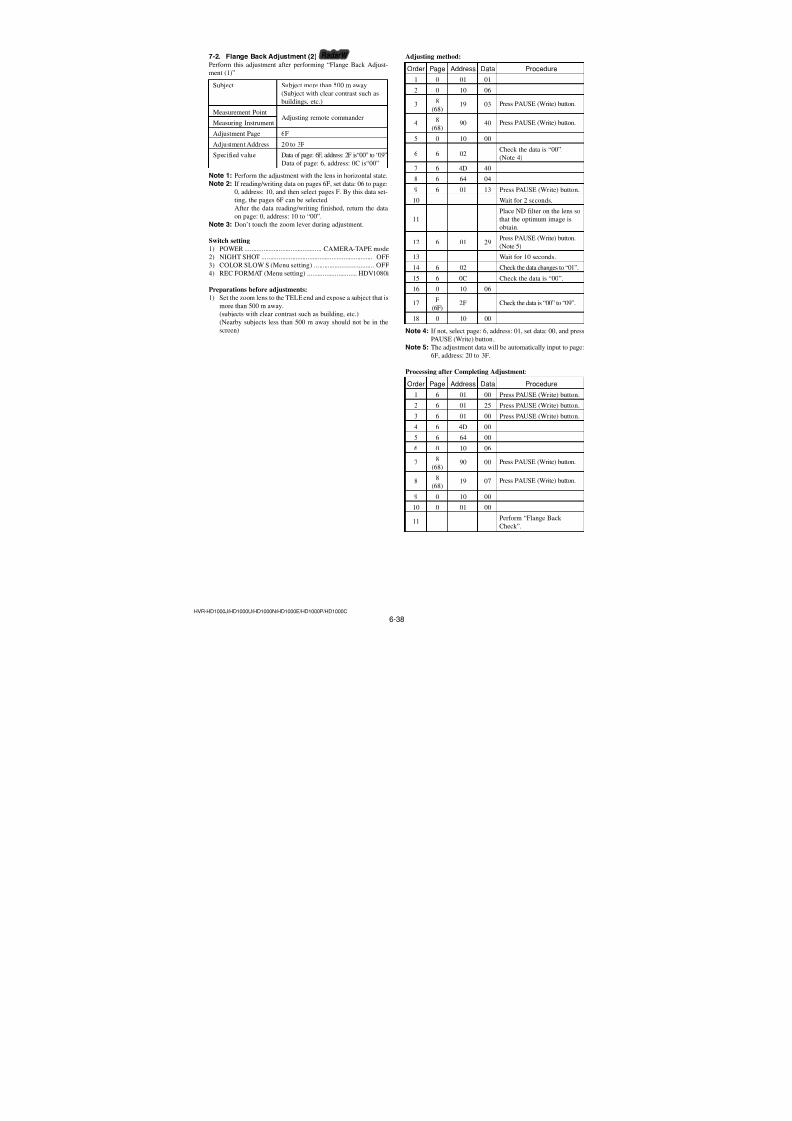
7/18/2019 SONY+HVR-HD1000 SERVICE MANUAL
http://slidepdf.com/reader/full/sonyhvr-hd1000-service-manual 170/4256-22HVR-HD1000J/HD1000U/HD1000N/HD1000E/HD1000P/HD1000C
11. 6A Page tableNote 1: If reading/writing data on pages 6A, set data: 06 to page:
0, address: 10, and then select pages: A. By this data set-
ting, the pages 6A can be selected.
After the data reading/writing finished, return the data
on page: 0, address: 10 to “00”.
Note 2: Fixed data-1: Initialized data. (Refer to “1. Initializing
of F, 63 to 6F Page Data”)Fixed data-2: Modified data. (Refer to “2. Modificationof F, 63 to 6F Page Data”)
AddressInitial value
RemarkNTSC PAL
00 to FF Fixed data-1 (Initialized data)
12. 6B Page tableNote 1: If reading/writing data on pages 6B, set data: 06 to page:
0, address: 10, and then select pages: B. By this data set-
ting, the pages 6B can be selected.
After the data reading/writing finished, return the data
on page: 0, address: 10 to “00”.
Note 2: Fixed data-1: Initialized data. (Refer to “1. Initializing
of F, 63 to 6F Page Data”)Fixed data-2: Modified data. (Refer to “2. Modification
of F, 63 to 6F Page Data”)
AddressInitial value
RemarkNTSC PAL
00 to 0C Fixed data-1 (Initialized data)
0D Fixed data-2
0E to 83 Fixed data-1 (Initialized data)
84 Fixed data-2
85 to BD Fixed data-1 (Initialized data)
BE Fixed data-2
BF to FF Fixed data-1 (Initialized data)
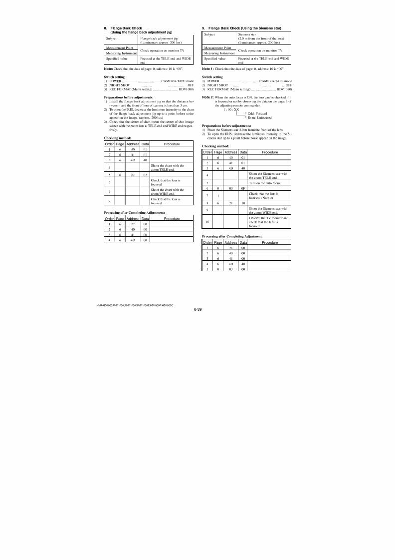
7/18/2019 SONY+HVR-HD1000 SERVICE MANUAL
http://slidepdf.com/reader/full/sonyhvr-hd1000-service-manual 171/4256-23HVR-HD1000J/HD1000U/HD1000N/HD1000E/HD1000P/HD1000C
AddressInitial value
RemarkNTSC PAL
EB
EC Fixed data-2
ED
EE to F0 Fixed data-1 (Initialized data)
F1
F2
F3
F4
F5 Fixed data-2
F6
F7
F8
F9, FA Fixed data-1 (Initialized data)
FB Fixed data-2FC to FF Fixed data-1 (Initialized data)
13. 6C Page tableNote 1: If reading/writing data on pages 6C, set data: 06 to page:
0, address: 10, and then select pages: C. By this data set-
ting, the pages 6C can be selected.
After the data reading/writing finished, return the data
on page: 0, address: 10 to “00”.
Note 2: Fixed data-1: Initialized data. (Refer to “1. Initializing
of F, 63 to 6F Page Data”)Fixed data-2: Modified data. (Refer to “2. Modificationof F, 63 to 6F Page Data”)
AddressInitial value
RemarkNTSC PAL
00 to 2E Fixed data-1 (Initialized data)
2F Fixed data-2
30 to 34 Fixed data-1 (Initialized data)
35
36 Fixed data-2
37
38 to 50 Fixed data-1 (Initialized data)
51 Fixed data-2
52 to 7B Fixed data-1 (Initialized data)
7C Fixed data-2
7D to 82 Fixed data-1 (Initialized data)
83 Fixed data-2
84 to 8B Fixed data-1 (Initialized data)
8C
8DFixed data-2
8E to AF Fixed data-1 (Initialized data)
B0
B1
B2 Fixed data-2
B3
B4
B5 Fixed data-1 (Initialized data)
B6
B7
B8
B9 Fixed data-2
BABB
BC
BD Fixed data-1 (Initialized data)
BE
BFFixed data-2
C0 to E2 Fixed data-1 (Initialized data)
E3 Fixed data-2
E4 Fixed data-1 (Initialized data)
E5
E6 Fixed data-2
E7
E8 Fixed data-1 (Initialized data)
E9
EAFixed data-2
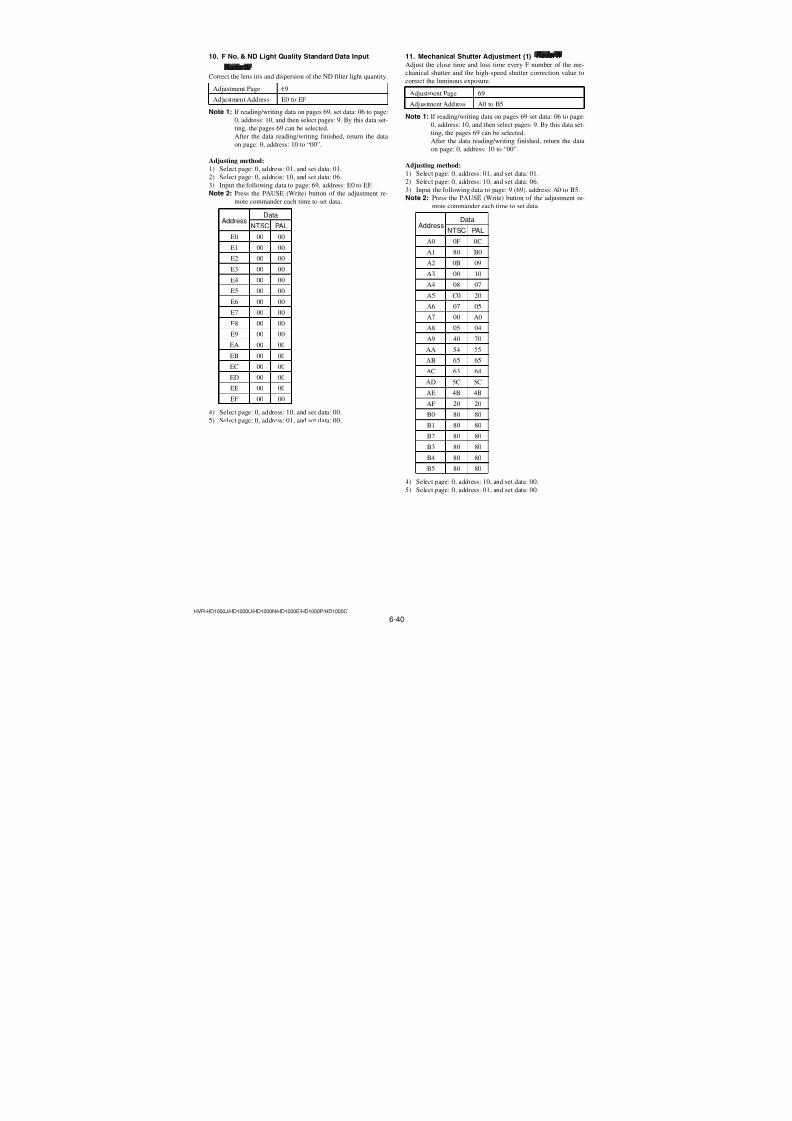
7/18/2019 SONY+HVR-HD1000 SERVICE MANUAL
http://slidepdf.com/reader/full/sonyhvr-hd1000-service-manual 172/4256-24HVR-HD1000J/HD1000U/HD1000N/HD1000E/HD1000P/HD1000C
14. 6D Page tableNote 1: If reading/writing data on pages 6D, set data: 06 to page:
0, address: 10, and then select pages: D. By this data
setting, the pages 6D can be selected.
After the data reading/writing finished, return the data
on page: 0, address: 10 to “00”.
Note 2: Fixed data-1: Initialized data. (Refer to “1. Initializing
of F, 63 to 6F Page Data”)Fixed data-2: Modified data. (Refer to “2. Modificationof F, 63 to 6F Page Data”)
AddressInitial value
RemarkNTSC PAL
00 to 05 Fixed data-1 (Initialized data)
06 Fixed data-2
07 Fixed data-1 (Initialized data)
08
09Fixed data-2
0A Fixed data-1 (Initialized data)
0B Fixed data-2
0C to 2F Fixed data-1 (Initialized data)
30 Fixed data-2
31 to 33 Fixed data-1 (Initialized data)
34
35Fixe data-2
36, 37 Fixed data-1 (Initialized data)
38
39 Fixed data-2
3A
3B to 49 Fixed data-1 (Initialized data)
4A
4B Fixed data-2
4C
4D to 5F Fixed data-1 (Initialized data)
60
61
62
63
64Fixed data-2
6566
67
68 to 8F Fixed data-1 (Initialized data)
90
91
92
93Fixed data-2
94
95
96 to 99 Fixed data-1 (Initialized data)
9A
9BFixed data-2
9C to 9F Fixed data-1 (Initialized data)
AddressInitial value
RemarkNTSC PAL
A0
A1 Fixed data-2
A2
A3 to A7 Fixed data-1 (Initialized data)
A8
A9Fixed data-2
AA to BF Fixed data-1 (Initialized data)
C0
C1
C2Fixed data-2
C3
C4 to D0 Fixed data-1 (Initialized data)
D1
D2 Fixed data-2D3
D4 to E2 Fixed data-1 (Initialized data)
E3 Fixed data-2
E4 to FF Fixed data-1 (Initialized data)
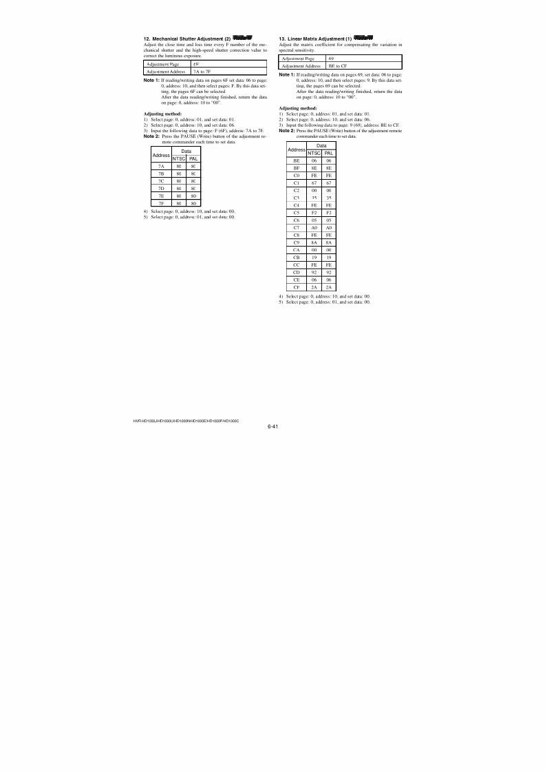
7/18/2019 SONY+HVR-HD1000 SERVICE MANUAL
http://slidepdf.com/reader/full/sonyhvr-hd1000-service-manual 173/4256-25HVR-HD1000J/HD1000U/HD1000N/HD1000E/HD1000P/HD1000C
AddressInitial value
RemarkNTSC PAL
29 00 00
2A 00 00
2B 00 00
2C 00 00
2D 00 00
2E 00 00
2F 00 00
30 00 00
31 00 00
32 00 00
33 00 00
34 00 00
35 00 00
36 00 0037 00 00
38 00 00
39 00 00
3A 00 00
3B 00 00
3C 00 00
3D 00 00
3E 00 00 Differential gain adj.
3F 00 00
40 00 00
41 00 00
42 00 00
43 00 00
44 00 00
45 00 00
46 00 00
47 00 00
48 00 00
49 00 00
4A 00 00
4B 00 00
4C 00 00
4D 00 00
4E 00 00
4F 00 00
50 00 00
51 00 00
52 00 00
53 00 00
54 00 00
55 00 0056 00 00
57 00 00
58 00 00
15. 6E Page tableNote 1: If reading/writing data on pages 6E, set data: 06 to page:
0, address: 10, and then select pages: E. By this data set-
ting, the pages 6E can be selected.
After the data reading/writing finished, return the data
on page: 0, address: 10 to “00”.
Note 2: Fixed data-1: Initialized data. (Refer to “1. Initializing
of F, 63 to 6F Page Data”)Fixed data-2: Modified data. (Refer to “2. Modificationof F, 63 to 6F Page Data”)
AddressInitial value
RemarkNTSC PAL
00 00 00
01 00 00
02 00 00
03 00 00
04 00 00
05 00 00
06 00 00
07 00 00
08 00 00
09 00 00
0A 00 00
0B 00 00
0C 00 00
0D 00 00
0E 00 00
0F 00 00
10 00 00
11 00 00
12 00 00 Differential gain adj.
13 00 00
14 00 00
15 00 00
16 00 00
17 00 00
18 00 00
19 00 00
1A 00 001B 00 00
1C 00 00
1D 00 00
1E 00 00
1F 00 00
20 00 00
21 00 00
22 00 00
23 00 00
24 00 00
25 00 00
26 00 00
27 00 00
28 00 00
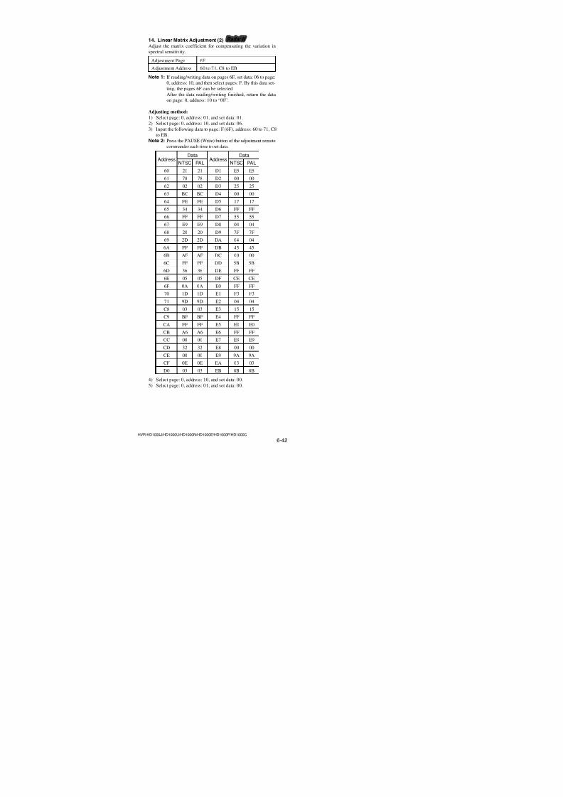
7/18/2019 SONY+HVR-HD1000 SERVICE MANUAL
http://slidepdf.com/reader/full/sonyhvr-hd1000-service-manual 174/4256-26HVR-HD1000J/HD1000U/HD1000N/HD1000E/HD1000P/HD1000C
6E Page table
AddressInitial value
RemarkNTSC PAL
59 00 00
5A 00 00
5B 00 00
5C 00 00
5D 00 00
5E 00 00
5F 00 00
60 00 00
61 00 00
62 00 00
63 00 00
64 00 00
65 00 0066 00 00
67 00 00
68 00 00
69 00 00
6A 00 00
6B 00 00
6C 00 00
6D 00 00
6E 00 00
6F 00 00 Differential gain adj.
70 00 00
71 00 00
72 00 00
73 00 00
74 00 00
75 00 00
76 00 00
77 00 00
78 00 00
79 00 00
7A 00 00
7B 00 00
7C 00 00
7D 00 00
7E 00 00
7F 00 00
80 00 00
81 00 00
82 00 00
83 00 00
84 00 0085 00 00
86 00 00
87 00 00
AddressInitial value
RemarkNTSC PAL
88 00 00
89 00 00
8A 00 00
8B 00 00
8C 00 00
8D 00 00
8E 00 00
8F 00 00
90 00 00
91 00 00
92 00 00
93 00 00
94 00 00
95 00 0096 00 00
97 00 00
98 00 00
99 00 00
9A 00 00
9B 00 00
9C 00 00 Differential gain adj.
9D 00 00
9E 00 00
9F 00 00
A0 00 00
A1 00 00
A2 00 00
A3 00 00
A4 00 00
A5 00 00
A6 00 00
A7 00 00
A8 00 00
A9 00 00
AA 00 00
AB 00 00
AC 00 00
AD 00 00
AE 00 00
AF 00 00
B0 00 00
B1 00 00
B2 00 00
B3 00 00
B4 to FF Fixed data-1 (Initialized data)
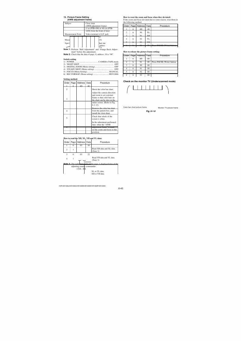
7/18/2019 SONY+HVR-HD1000 SERVICE MANUAL
http://slidepdf.com/reader/full/sonyhvr-hd1000-service-manual 175/4256-27HVR-HD1000J/HD1000U/HD1000N/HD1000E/HD1000P/HD1000C
16. 6F Page tableNote 1: If reading/writing data on pages 6F, set data: 06 to page:
0, address: 10, and then select pages: F. By this data set-
ting, the pages 6F can be selected.
After the data reading/writing finished, return the data
on page: 0, address: 10 to “00”.Note 2: Fixed data-1: Initialized data. (Refer to “1. Initializing
of F, 63 to 6F Page Data”)Fixed data-2: Modified data. (Refer to “2. Modification
of F, 63 to 6F Page Data”)
AddressInitial value
RemarkNTSC PAL
10 to 1F Fixed data-1 (Initialized data)
20 12 12
21 43 43
22 54 54
23 90 90
24 22 22
25 FE FE
26 00 00
27 00 00
28 00 00Flange back adj.
29 00 00
2A B3 B3
2B 19 19
2C 19 19
2D 45 45
2E 00 00
2F 06 06
30 00 00 MR adj. / Flange back adj.
31 00 00
32 00 00
33 00 00
34 00 00
35 00 00
36 00 00
37 00 00
38 00 00 Flange back adj.
39 00 003A 00 00
3B 00 00
3C 00 00
3D 00 00
3E 00 00
3F 00 00
40 80 80
41 80 80
42 80 80
43 80 80
44 40 40MR adj.
45 C0 C0
46 40 40
47 C0 C0
AddressInitial value
RemarkNTSC PAL
48 40 40
49 C0 C0
4A 40 40
4B C0 C0
4C 00 00MR adj.
4D 00 00
4E 00 00
4F 00 00
50 to 5F Fixed data-1 (Initialized data)
60 21 21
61 B3 B3
62 02 02
63 63 63
64 FE FE65 C1 C1
66 FF FF
67 DA DA
68 20 20
69 0A 0ALinear matrix adj. (2)
6A 00 00
6B 2C 2C
6C FF FF
6D 43 43
6E 04 04
6F F6 F6
70 1D 1D
71 BC BC
72 to 79 Fixed data-1 (Initialized data)
7A 80 80
7B 80 80
7C 80 80
7D 80 80Mechanical shutter adj. (2)
7E 80 80
7F 80 80
80 to 83 Fixed data-1 (Initialized data)
84 2A 2A
85 80 80
86 5E 5EAWB adj.
87 40 40
88 14 14
89 D3 D3
8A 05 05
8B B0 B0
8C 14 14 AWB standard data input
8D B4 B48E 05 05
8F AC AC
90 14 14
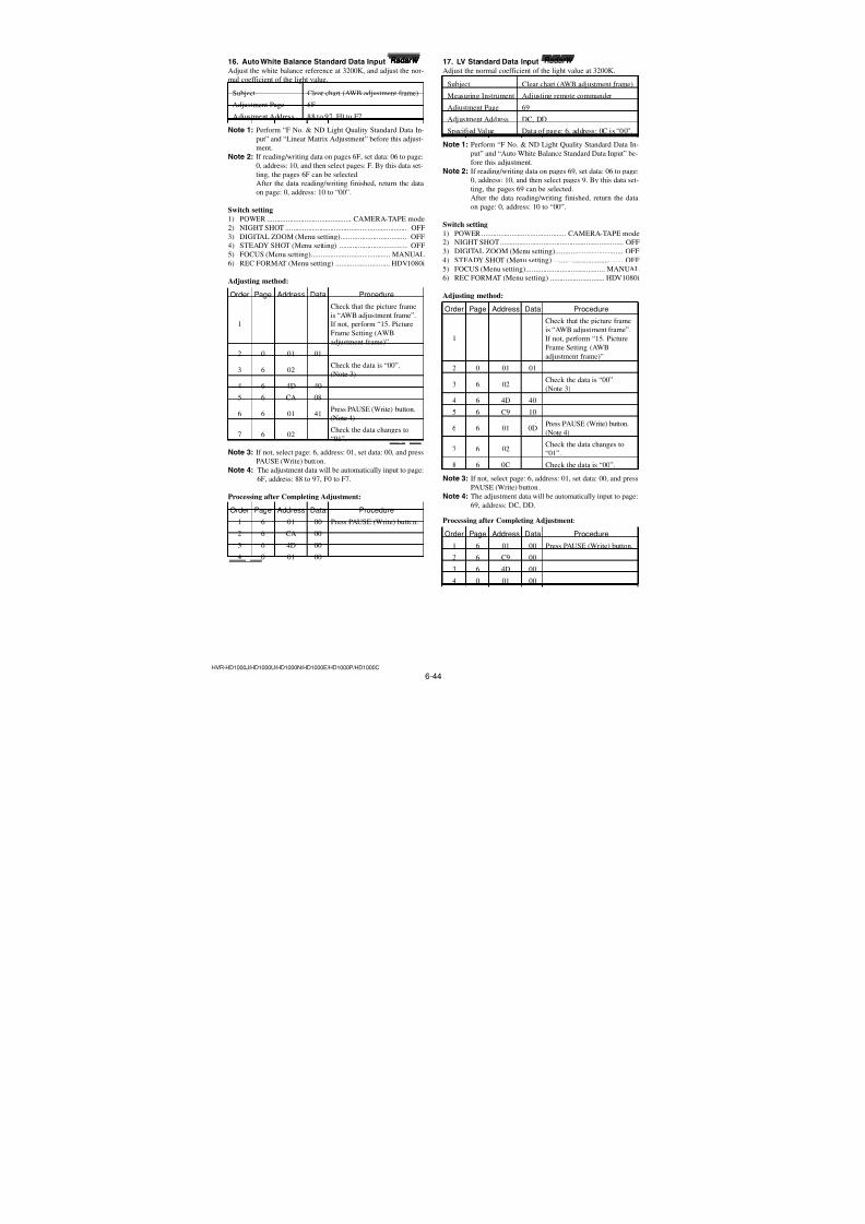
7/18/2019 SONY+HVR-HD1000 SERVICE MANUAL
http://slidepdf.com/reader/full/sonyhvr-hd1000-service-manual 176/4256-28HVR-HD1000J/HD1000U/HD1000N/HD1000E/HD1000P/HD1000C
6F Page table
AddressInitial value
RemarkNTSC PAL
91 AE AE
92 05 05
93 A6 A6
94 14 14 AWB standard data input
95 B2 B2
96 05 05
97 A5 A5
98 0C 0C
99 4E 4E
9A 09 09
9B 08 08
9C 0C 0C
9D 39 399E 09 09
9F 02 02
A0 0C 0CAWB adj.
A1 34 34
A2 08 08
A3 FC FC
A4 0C 0C
A5 2D 2D
A6 08 08
A7 F3 F3
A8 E5 E5
A9 DB DB
AA 6E 6E
AB 58 58
AC 05 05
AD 11 11
AE 65 65
AF 6C 6C
B0 E5 E5Color reproduction adj. & check
B1 DB DB
B2 6E 6E
B3 58 58
B4 05 05
B5 11 11
B6 65 65
B7 6C 6C
B8 to C7 Fixed data-1 (Initialized data)
C8 03 03
C9 AA AA
CA FF FF
CB B5 B5 Linear matrix adj. (2)CC 00 00
CD 30 30
CE 00 00
AddressInitial value
RemarkNTSC PAL
CF 01 01
D0 03 03
D1 F0 F0
D2 00 00
D3 20 20
D4 00 00
D5 13 13
D6 FF FF
D7 54 54
D8 04 04
D9 87 87
DA 04 04
DB 5F 5F
DC 00 00DD 4C 4C Linear matrix adj. (2)
DE FF FF
DF D0 D0
E0 00 00
E1 00 00
E2 04 04
E3 0B 0B
E4 FF FF
E5 E4 E4
E6 FF FF
E7 EE EE
E8 00 00
E9 99 99
EA 03 03
EB 85 85
EC to EF Fixed data-1 (Initialized data)
F0 14 14
F1 AD AD
F2 05 05
F3 A7 A7
F4 14 14 AWB standard data input
F5 95 95
F6 05 05
F7 AA AA
F8 0C 0C
F9 37 37
FA 09 09
FB 01 01
FC 0C 0CAWB adj.
FD 0A 0A
FE 09 09FF 02 02
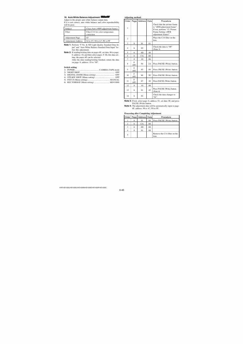
7/18/2019 SONY+HVR-HD1000 SERVICE MANUAL
http://slidepdf.com/reader/full/sonyhvr-hd1000-service-manual 177/4256-29HVR-HD1000J/HD1000U/HD1000N/HD1000E/HD1000P/HD1000C
1-2-4. Initialization of 7C, 7E, 7F Page Data
1. Initializing of 7C, 7E, 7F Page DataNote 1: If “Initialization of Pages 7C, 7E, 7F” is executed, all
data on pages 7C, 7E, 7F are initialized.
(Only an individual page cannot be initialized)
Note 2: If the 7C, 7E, 7F page data has been initialized, the fol-
lowing adjustments need to be performed again.1) Modification of 7C, 7E, 7F page data2) HALL adjustment (1) (if all areas were initialized)
3) Angular velocity sensor sensitivity adjustment (if all
areas were initialized)
Adjustment Page 7C
Adjustment Address 00 to FF
Adjustment Page 7E
Adjustment Address 00 to FF
Adjustment Page 7F
Adjustment Address 00 to FF
Initializing method:
Order Page Address Data Procedure
1 0 01 01
2 0 10 07
32
01 2D Press PAUSE (Write) button.(72)
42
02Check the data changes to
(72) “01”.
52
01 00 Press PAUSE (Write) button.(72)
6 0 10 00
7Perform “Modification of
7C, 7E, 7F Page Data”.
2. Modification of 7C, 7E, 7F Page DataIf the 7C, 7E, 7F page data has been initialized, change the data of the “Fixed data-2” address shown in the following table by manual
input.
Modifying Method:
1) Before changing the data, select page: 0, address: 01, and set
data: 01.2) If modification of data on pages 7C, 7E, 7F, set data: 01 to
page: 0, address: 10, and then select pages C, E, F.
After the modification of data finished, return the data on page:
0, address: 10 to “00”.
3) New data for changing are not shown in the tables because
they are different in destination. When changing the data, copy
the data built in the same model.Note: If copy the data built in the different model, the
camcorder may not operate.4) When changing the data, press the PAUSE (Write) button of
the adjustment remote commander each time when setting new
data to write the data in the non-volatile memory.
5) If all areas were initialized, check that the data at the addresses
for adjustment are initial values (adjustment initial values)
listed in the table. If different, change them to the adjustment
initial values.
Processing after Completing Modification Camera Control
Data:
Order Page Address Data Procedure
1 0 10 00
2 2 00 29
3 2 01 29 Press PAUSE (Write) button.
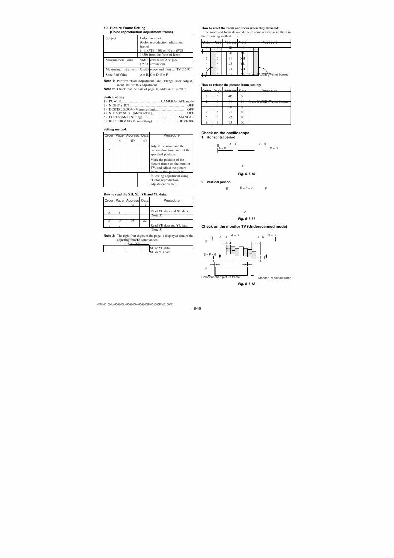
7/18/2019 SONY+HVR-HD1000 SERVICE MANUAL
http://slidepdf.com/reader/full/sonyhvr-hd1000-service-manual 178/4256-30HVR-HD1000J/HD1000U/HD1000N/HD1000E/HD1000P/HD1000C
3. 7C Page tableNote 1: If reading/writing data on pages 7C, set data: 07 to page:
0, address: 10, and then select pages: C. By this data set-
ting, the pages 7C can be selected.
After the data reading/writing finished, return the data
on page: 0, address: 10 to “00”.
Note 2: Fixed data-1: Initialized data. (Refer to “1. Initializing
of 7C, 7E, 7F Page Data”)Fixed data-2: Modified data. (Refer to “2. Modificationof 7C, 7E, 7F Page Data”)
AddressInitial value
RemarkNTSC PAL
00 to 11 Fixed data-1 (Initialized data)
12
13
14Fixed data-2
15
16, 17 Fixed data-1 (Initialized data)
18
19Fixed data-2
1A to FF Fixed data-1 (Initialized data)
4. 7E Page tableNote 1: If reading/writing data on pages 7E, set data: 07 to page:
0, address: 10, and then select pages: E. By this data set-
ting, the pages 7E can be selected.
After the data reading/writing finished, return the data
on page: 0, address: 10 to “00”.
Note 2: Fixed data-1: Initialized data. (Refer to “1. Initializing
of 7C, 7E, 7F Page Data”)Fixed data-2: Modified data. (Refer to “2. Modificationof 7C, 7E, 7F Page Data”)
AddressInitial value
RemarkNTSC PAL
00 to 16 Fixed data-1 (Initialized data)
17 Fixed data-2
18 to 1B Fixed data-1 (Initialized data)
1C Fixed data-2
1D Fixed data-1 (Initialized data)
1E
1FFixed data-2
20 to 50 Fixed data-1 (Initialized data)
51 Fixed data-2
52 Fixed data-1 (Initialized data)
53 Fixed data-2
54 to AA Fixed data-1 (Initialized data)
AB Fixed data-2
AC, AD Fixed data-1 (Initialized data)
AE Fixed data-2
AF to C3 Fixed data-1 (Initialized data)
C4
C5Fixed data-2
C6 to EF Fixed data-1 (Initialized data)
F0 Fixed data-2
F1 to FF Fixed data-1 (Initialized data)
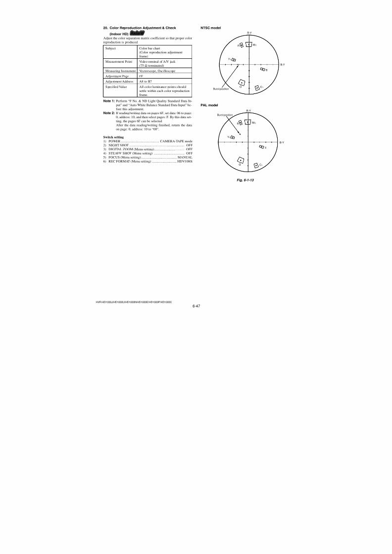
7/18/2019 SONY+HVR-HD1000 SERVICE MANUAL
http://slidepdf.com/reader/full/sonyhvr-hd1000-service-manual 179/4256-31HVR-HD1000J/HD1000U/HD1000N/HD1000E/HD1000P/HD1000C
5. 7F Page tableNote 1: If reading/writing data on pages 7F, set data: 07 to page:
0, address: 10, and then select pages: F. By this data set-
ting, the pages 7F can be selected.
After the data reading/writing finished, return the data
on page: 0, address: 10 to “00”.
Note 2: Fixed data-1: Initialized data. (Refer to “1. Initializing
of 7C, 7E, 7F Page Data”)Fixed data-2: Modified data. (Refer to “2. Modificationof 7C, 7E, 7F Page Data”)
AddressInitial value
RemarkNTSC PAL
00 to 03 Fixed data-1 (Initialized data)
04 80 80
05 80 80
06 80 80
07 80 80
08 03 03
09 77 77
0A 03 03HALL adj. (1)
0B 79 79
0C 00 00
0D A3 A3
0E 00 00
0F 83 83
10, 11 Fixed data-1 (Initialized data)
12 36 36 Angular velocity sensor sensitive
13 36 36 adj.
14 to FF Fixed data-1 (Initialized data)
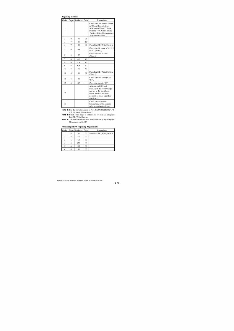
7/18/2019 SONY+HVR-HD1000 SERVICE MANUAL
http://slidepdf.com/reader/full/sonyhvr-hd1000-service-manual 180/4256-32HVR-HD1000J/HD1000U/HD1000N/HD1000E/HD1000P/HD1000C
1-3. CAMERA SYSTEM ADJUSTMENTSBefore perform the camera system adjustments, check that the
specified values of “VIDEO SYSTEM ADJUSTMENTS” are sat-isfied. (Except Origin Oscillation Check”)
Check that the data of page: 0, address: 10 is “00”.
If not, select page: 0, address: 10, and set the data “00”.
1. Origin Oscillation Check (CM-077 board)Check the frequency of the clock for synchronization.
If deviated, the synchronization will be disrupted and the colorwill become inconsistent.
Subject Not required
Measurement Point Pin qh of CN6601 on CM-077 board
Measuring Instrument Frequency counter
Specified value f = 44505494 ± 895 Hz (NTSC)
f = 37125000 ± 745 Hz (PAL)
Switch setting
1) POWER ............................................. CAMERA-TAPE mode
Checking method:
1) Check that the frequency (f) satisfies the specified value.
Fig. 6-1-6
16
CN66011 40
CM-077 BOARD (SIDE B)
2. HALL Adjustment (1) RadarW adarRadarW adarRadarW
Adjust the offset and gain to eliminate the output dispersion of theHall sensor.
Subject Not required
Measurement PointAdjusting remote commander
Measuring Instrument
Adjustment Page 7F
Adjustment Address 04 to 0F
Specified value Data of page: 72 address: 03 is “00”
Data of page: 72 address: 04 is “00”
Note 1: If reading/writing data on pages 72, 7F set data: 07 to
page: 0, address: 10, and then select pages: 2, F. By this
data setting, the pages 72, 7F can be selected.
After the data reading/writing finished, return the data
on page: 0, address: 10 to “00”.Note 2: Perform this adjustment only when replacing the lens
block. When the microprocessor, circuit etc. is damaged,don't perform this adjustment but check the steady shot
operations only.
Note 3: Perform the adjustment with the camcorder in horizontal
state.
Note 4: Do not move the set.
Switch setting
1) POWER ............................................. CAMERA-TAPE mode
Adjusting method:
Order Page Address Data Procedure
1 0 01 01
2 0 10 07
2 Press PAUSE (Write) button.3(72)
01 97(Note 5)
4 Wait for 4 seconds.
2 Check the data changes to5(72)
02“01”.
2 Check the data is “00”.6(72)
03(Note 6)
72 Check the data is “00”.
(72)04
(Note 6).
Note 5: The adjustment data will be automatically input to page:
7F, address: 04 to 0F.Note 6: If the data is other than “00”, perform readjustment.
Processing after Completing Adjustment:
Order Page Address Data Procedure
21(72)
01 00 Press PAUSE (Write) button.
2 0 10 00
3 0 01 00
4Turn off the power and turn
on again.
5
Shake the camcorder
vertically and horizontally to
check that the steady shot
function operates normally.
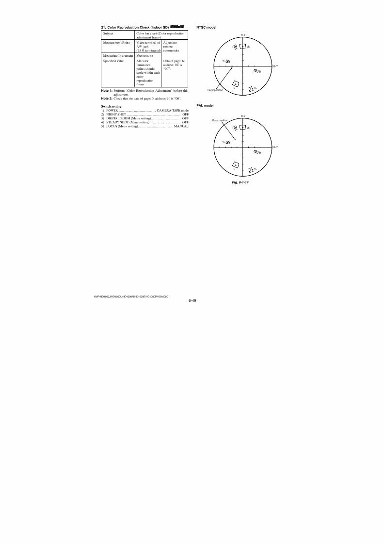
7/18/2019 SONY+HVR-HD1000 SERVICE MANUAL
http://slidepdf.com/reader/full/sonyhvr-hd1000-service-manual 181/4256-33HVR-HD1000J/HD1000U/HD1000N/HD1000E/HD1000P/HD1000C
4. MR Adjustment adaradarRadarW
The inner focus lens MR adjustment is carried out automatically.In whichever case, the focus will be deviated during auto focus-
ing/manual focusing.
Subject Not required
Measurement Point
Adjusting remote commanderMeasuring Instrument
Adjustment Page 6F
Adjustment Address 30, 40 to 4F
Specified value Data of page: 6, address: 0C is “00”.
Note 1: Perform the adjustment with the lens in horizontal state.
Note 2: Perform “Flange Back Adjustment” after this adjustment.Note 3: If reading/writing data on pages 6F, set data: 06 to page:
0, address: 10, and then select pages F. By this data set-ting, the pages 6F can be selected.
After the data reading/writing finished, return the data
on page: 0, address: 10 to “00”.
Switch setting1) POWER .............................................CAMERA-TAPE mode
Adjusting method:
Order Page Address Data Procedure
1 0 01 01
2 6 02Check the data is “00”.
(Note 4)
3 Wait for 2 seconds.
4 6 01 BD Press PAUSE (Write) button.
(Note 5)
5 6 02Check the data changes to
“01”.
6 6 0C Check the data is “00”.
Note 4: If not, select page: 6, address: 01, set data: 00, and press
the PAUSE (Write) button.
Note 5: The adjustment data will be automatically input to page:
6F, address: 30, 40 to 4F.
Processing after Completing Adjustment:
Order Page Address Data Procedure
1 6 01 00 Press PAUSE (Write) button.
2 6 01 25 Press PAUSE (Write) button.
3 Wait for 2 seconds.
4 6 02Check the data changes to
“01”.
5 6 01 00 Press PAUSE (Write) button.
6 0 01 00
3. HALL Adjustment (2) adaradarRadarW
For detecting the position of lens iris and ND filter, adjust the hallAMP gain and offset.
Subject Not required
Measurement Point
Measuring InstrumentAdjusting remote commander
Adjustment Page 69
Adjustment Address D0 to D8
Specified value Data of page: 6, address: 0C is “00”
Note 1: If reading/writing data on pages 69, set data: 06 to page:
0, address: 10, and then select pages 9. By this data set-
ting, the pages 69 can be selected.
After the data reading/writing finished, return the data
on page: 0, address: 10 to “00”.
Switch setting
1) POWER ............................................. CAMERA-TAPE mode
Adjusting method:
Order Page Address Data Procedure
1 0 01 01
2 6 02Check the data is “00”.
(Note 2)
3 6 D0 22
4 6 01 6D Press PAUSE (Write) button.
(Note 3)
5 6 02 Check the data changes to “01”.
6 6 0C Check the data is “00”.
Note 2: If not, select page: 6, address: 01, set data: 00, and press
the PAUSE (Write) button.Note 3: The adjustment data will be automatically input to page:
69, address: D0 to D8.
Processing after Completing Adjustment:
Order Page Address Data Procedure
1 6 01 00 Press PAUSE (Write) button.
2 0 01 00
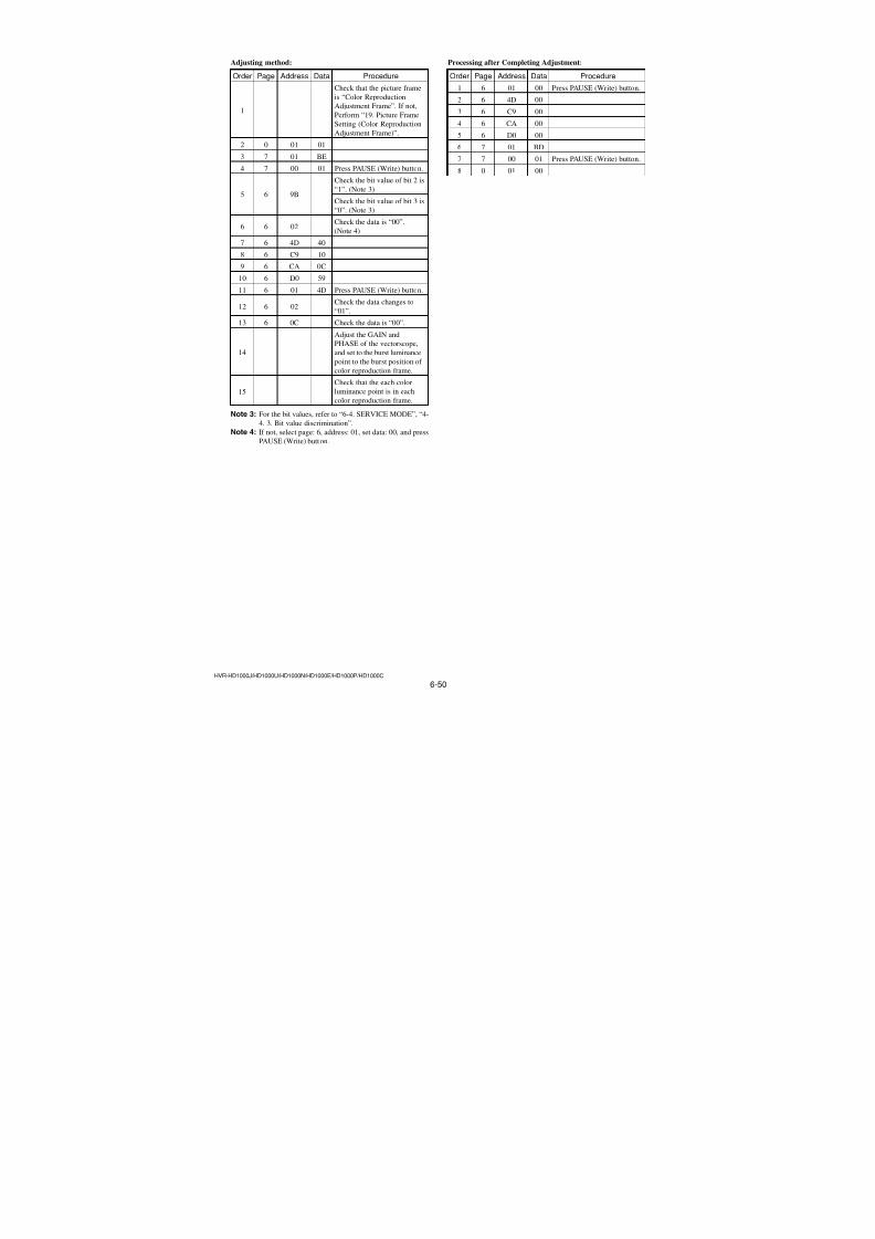
7/18/2019 SONY+HVR-HD1000 SERVICE MANUAL
http://slidepdf.com/reader/full/sonyhvr-hd1000-service-manual 182/4256-34HVR-HD1000J/HD1000U/HD1000N/HD1000E/HD1000P/HD1000C
5. Differential Gain Adjustment RadarW adarRadarW adarRadarW
Correct the dispersion of between the channels of CMOS imager.
Subject Clear chart (All white) (Note 1)
Adjustment Page 6E
Adjustment Address 00 to B3
Note 1: Shoot the clear chart with the zoom TELE end.Note 2: If reading/writing data on pages 6E set data: 06 to page:
0, address: 10, and then select pages: E. By this data set-
ting, the pages 6E can be selected.
After the data reading/writing finished, return the data
on page: 0, address: 10 to “00”.
Switch setting
1) POWER ............................................. CAMERA-TAPE mode
2) NIGHT SHOT .................................................................. OFF
3) ZOOM ..................................................................... TELE end
4) STEADY SHOT (Menu setting) ..................................... OFF
5) FOCUS (Menu setting).......................................... MANUAL
Adjusting method:
Order Page Address Data Procedure
1 0 01 01
2 6 02Check the data is “00”.(Note 3)
3 6 2C 01
4 6 40 01
5 6 D0 60
6 6 D2 01
7 6 D3 01
8 6 D6 10
9 6 01 F5Press PAUSE (Write) button.(Note 4)
10 Wait for 3 seconds.
11 6 02Check the data changes to
“01”.
Note 3: If not, select page: 6, address: 01, set data: 00, and pressPAUSE (Write) button.
Note 4: The adjustment data will be automatically input to page:
6E, address: 00 to B3.
Processing after Completing Adjustment:
Order Page Address Data Procedure1 6 01 00 Press PAUSE (Write) button.
2 6 2C 00
3 6 40 00
4 0 01 00
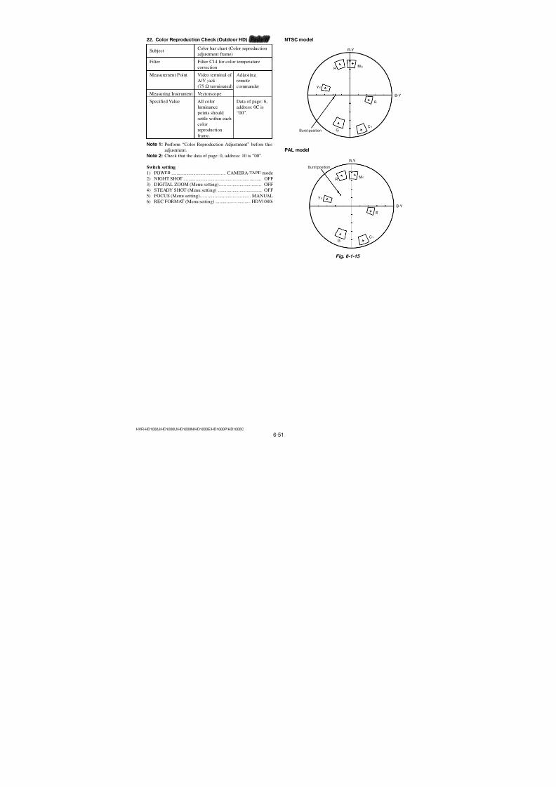
7/18/2019 SONY+HVR-HD1000 SERVICE MANUAL
http://slidepdf.com/reader/full/sonyhvr-hd1000-service-manual 183/4256-35HVR-HD1000J/HD1000U/HD1000N/HD1000E/HD1000P/HD1000C
6. Flange Back Adjustment RadarW adarRadarW adarRadarW
(Using the minipattern box or flange back adjust-ment jig)
The inner focus lens flange back adjustment is carried out auto-
matically. In whichever case, the focus will be deviated during
auto focusing/manual focusing.
Subject Siemens star chart with ND filter forminipattern box (Note 1) or flangeback adjustment jig
Measurement Point
Measuring InstrumentAdjusting remote commander
Adjustment Page 6F
Adjustment Address 20 to 3F
Specified value Data of page: 6F, address: 2F is
“00” to “09”
Data of pege: 6, address: 0C is “00”
Note 1: Dark Siemens star chart.
Note 2: Perform “HALL Adjustment”, “MR Adjustment” and
“Differential Gain Adjustment” before this adjustment.Note 3: Perform the adjustment with the lens in horizontal state.Note 4: If reading/writing data on pages 6F, set data: 06 to page:
0, address: 10, and then select pages F. By this data set-
ting, the pages 6F can be selected.
After the data reading/writing finished, return the data
on page: 0, address: 10 to “00”.
Note 5: Don't touch the zoom lever during adjustment.
Note 6: After adjustment, if the focusing to a subject located at
infinity failed, increase the illuminance of the chart and
perform readjustment.
Switch setting
1) POWER ............................................. CAMERA-TAPE mode
2) NIGHT SHOT .................................................................. OFF3) COLOR SLOW S (Menu setting) ................................... OFF
4) REC FORMAT (Menu setting) ............................. HDV1080i
Preparation (Using the minipattern box)
1) The minipattern box is installed as shown in the following fig-ure.
Note 7: The attachment lenses are not used.
2) Install the minipattern box so that the distance between it and
the front of lens of camera is less than 3 cm.
3) Make the height of minipattern box and the camera equal.
4) Check the output voltage of the regulated power supply is thespecified voltage ± 0.01 Vdc.
5) Check that the center of Siemens star chart meets the center of
shot image screen with the zoom lens at TELE end and WIDE
end respectively.
Specified voltage: The specified voltage varies according to the
minipattern box, so adjustment the power sup-
ply output voltage to the specified voltage writ-ten on the sheet which is supplied with the mini-
pattern box.
Fig. 6-1-7
Preparation (Using the flange back adjustment jig)
(Luminance: 300 to 400 lux)
1) Install the flange back adjustment jig so that the distance be-
tween it and the front of lens of camera is less than 3 cm.
2) Make the height of flange back adjustment jig and the cameraequal.
3) Check that the center of chart meets the center of shot image
screen with the zoom lens at TELE end and WIDE end respec-tively.
Fig. 6-1-8
Minipattern box
Below 3 cm
Camera
Red (+)
Black (–)
Yellow (SENS +)
White (SENS –)
Black (GND)
Need not connected
Regulated power supplyOutput voltage : Specified voltage ± 0.01 Vdc
Output current : more than 3.5 A
Flange back adjustment jigBelow 3 cm
Camera
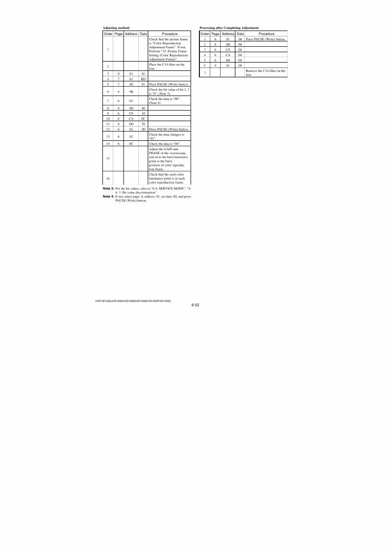
7/18/2019 SONY+HVR-HD1000 SERVICE MANUAL
http://slidepdf.com/reader/full/sonyhvr-hd1000-service-manual 184/4256-36HVR-HD1000J/HD1000U/HD1000N/HD1000E/HD1000P/HD1000C
Adjusting method:
Order Page Address Data Procedure
1 0 01 01
2 0 10 06
83
(68)
19 03 Press PAUSE (Write) button.
84(68)
90 40 Press PAUSE (Write) button.
5 0 10 00
6 6 02Check the data is “00”.
(Note 8)
7 6 4D 40
8 6 64 04
9 6 01 13 Press PAUSE (Write) button.
10 Wait for 2 seconds.
11 6 01 27Press PAUSE (Write) button.
(Note 9)
12 Wait for 10 seconds.
13 6 02 Check the data changes to “01”.
14 6 0C Check the data is “00”.
15 0 10 06
F16(6F)
2F Check the data is “00” to “09”.
17 0 10 00
Note 8: If not, select page: 6, address: 01, set data: 00, and press
PAUSE (Write) button.
Note 9: The adjustment data will be automatically input to page:
6F, address: 20 to 3F.
Processing after Completing Adjustment:
Order Page Address Data Procedure
1 6 01 00 Press PAUSE (Write) button.
2 6 01 25 Press PAUSE (Write) button.
3 6 01 00 Press PAUSE (Write) button.
4 6 4D 00
5 6 64 00
6 0 10 06
87(68)
90 00 Press PAUSE (Write) button.
88(68)
19 07 Press PAUSE (Write) button.
9 0 10 00
10 0 01 00
Perform “Flange Back 11Check”.
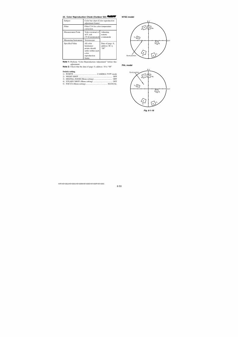
7/18/2019 SONY+HVR-HD1000 SERVICE MANUAL
http://slidepdf.com/reader/full/sonyhvr-hd1000-service-manual 185/4256-37HVR-HD1000J/HD1000U/HD1000N/HD1000E/HD1000P/HD1000C
Adjusting method:
Order Page Address Data Procedure
1 0 01 01
2 0 10 06
3 8 19 03
(68)
Press PAUSE (Write) button.
4 8 90 40(68)
Press PAUSE (Write) button.
5 0 10 00
6 6 02Check the data is “00”.
(Note 6)
7 6 4D 40
8 6 64 04
9 6 01 13 Press PAUSE (Write) button.
10 Wait for 2 seconds.
11 6 01 15Press PAUSE (Write) button.
(Note 7)
12 Wait for 10 seconds.
13 6 02Check the data changes to
“01”.
14 6 0C Check the data is “00”.
15 0 10 06
16 F 2F Check the data is “00” to
(6F) “09”.
17 0 10 00
Note 6: If not, select page: 6, address: 01, set data: 00, and press
PAUSE (Write) button.
Note 7: The adjustment data will be automatically input to page:
6F, address: 20 to 3F.
Processing after Completing Adjustment:
Order Page Address Data Procedure
1 6 01 00 Press PAUSE (Write) button.
2 6 01 25 Press PAUSE (Write) button.
3 6 01 00 Press PAUSE (Write) button.
4 6 4D 00
5 6 64 00
6 0 10 06
7 8 90 00(68)
Press PAUSE (Write) button.
8 8 19 07(68)
Press PAUSE (Write) button.
9 0 10 00
10 0 01 00
11 Perform “Flange Back
Adjustment (2)”.
7. Flange Back Adjustment(Using the flange back adjustment chart andsubject more than 500 m away)
The inner focus lens flange back adjustment is carried out auto-
matically. In whichever case, the focus will be deviated during
auto focusing/manual focusing.
7-1. Flange Back Adjustment (1) adaradarRadarW
Subject Flange back adjustment chart
(2.0 m from the front of lens)
(Luminance: 300 to 400 lux)
Measurement PointAdjusting remote commander
Measuring Instrument
Adjustment Page 6F
Adjustment Address 20 to 3F
Specified value Data of page: 6F, address: 2F is“00” to “09”
Data of pege: 6, address: 0C is “00”
Note 1: Perform “HALL Adjustment”, “MR Adjustment” and“Differential Gain Adjustment” before this adjustment.
Note 2: Perform the adjustment with the lens in horizontal state.Note 3: If reading/writing data on pages 6F, set data: 06 to page:
0, address: 10, and then select pages F. By this data set-
ting, the pages 6F can be selected.
After the data reading/writing finished, return the data
on page: 0, address: 10 to “00”.
Note 4: Don’t touch the zoom lever during adjustment.Note 5: After adjustment, if the focusing to a subject located at
infinity failed, increase the illuminance of the chart andperform readjustment.
Switch setting
1) POWER ............................................. CAMERA-TAPE mode2) NIGHT SHOT .................................................................. OFF
3) COLOR SLOW S (Menu setting) ................................... OFF
4) REC FORMAT (Menu setting) ............................. HDV1080i
Preparations before adjustments:
1) Check that the center of Flange back adjustment chart meets
the center of shot image screen with the zoom lens at TELE
end and WIDE end respectively.
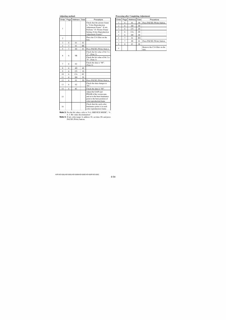
7/18/2019 SONY+HVR-HD1000 SERVICE MANUAL
http://slidepdf.com/reader/full/sonyhvr-hd1000-service-manual 186/4256-38HVR-HD1000J/HD1000U/HD1000N/HD1000E/HD1000P/HD1000C
Adjusting method:
Order Page Address Data Procedure
1 0 01 01
2 0 10 06
3 8 19 03
(68)
Press PAUSE (Write) button.
4 8 90 40(68)
Press PAUSE (Write) button.
5 0 10 00
6 6 02Check the data is “00”.
(Note 4)
7 6 4D 40
8 6 64 04
9 6 01 13 Press PAUSE (Write) button.
10 Wait for 2 seconds.
11
Place ND filter on the lens so
that the optimum image is
obtain.
12 6 01 29Press PAUSE (Write) button.
(Note 5)
13 Wait for 10 seconds.
14 6 02 Check the data changes to “01”.
15 6 0C Check the data is “00”.
16 0 10 06
17 F 2F Check the data is “00” to “09”.(6F)
18 0 10 00
Note 4: If not, select page: 6, address: 01, set data: 00, and press
PAUSE (Write) button.
Note 5: The adjustment data will be automatically input to page:
6F, address: 20 to 3F.
Processing after Completing Adjustment:
Order Page Address Data Procedure
1 6 01 00 Press PAUSE (Write) button.
2 6 01 25 Press PAUSE (Write) button.
3 6 01 00 Press PAUSE (Write) button.
4 6 4D 00
5 6 64 00
6 0 10 06
7 8 90 00(68)
Press PAUSE (Write) button.
8 8 19 07(68)
Press PAUSE (Write) button.
9 0 10 00
10 0 01 00
11Perform “Flange Back
Check”.
7-2. Flange Back Adjustment (2) adaradarRadarW
Perform this adjustment after performing “Flange Back Adjust-ment (1)”.
Subject Subject more than 500 m away
(Subject with clear contrast such as
buildings, etc.)
Measurement Point Adjusting remote commanderMeasuring Instrument
Adjustment Page 6F
Adjustment Address 20 to 3F
Specified value Data of page: 6F, address: 2F is“00” to “09”
Data of page: 6, address: 0C is“00”
Note 1: Perform the adjustment with the lens in horizontal state.Note 2: If reading/writing data on pages 6F, set data: 06 to page:
0, address: 10, and then select pages F. By this data set-
ting, the pages 6F can be selected.
After the data reading/writing finished, return the data
on page: 0, address: 10 to “00”.
Note 3: Don’t touch the zoom lever during adjustment.
Switch setting
1) POWER ............................................. CAMERA-TAPE mode
2) NIGHT SHOT .................................................................. OFF
3) COLOR SLOW S (Menu setting) ................................... OFF
4) REC FORMAT (Menu setting) ............................. HDV1080i
Preparations before adjustments:
1) Set the zoom lens to the TELE end and expose a subject that is
more than 500 m away.(subjects with clear contrast such as building, etc.)
(Nearby subjects less than 500 m away should not be in the
screen)
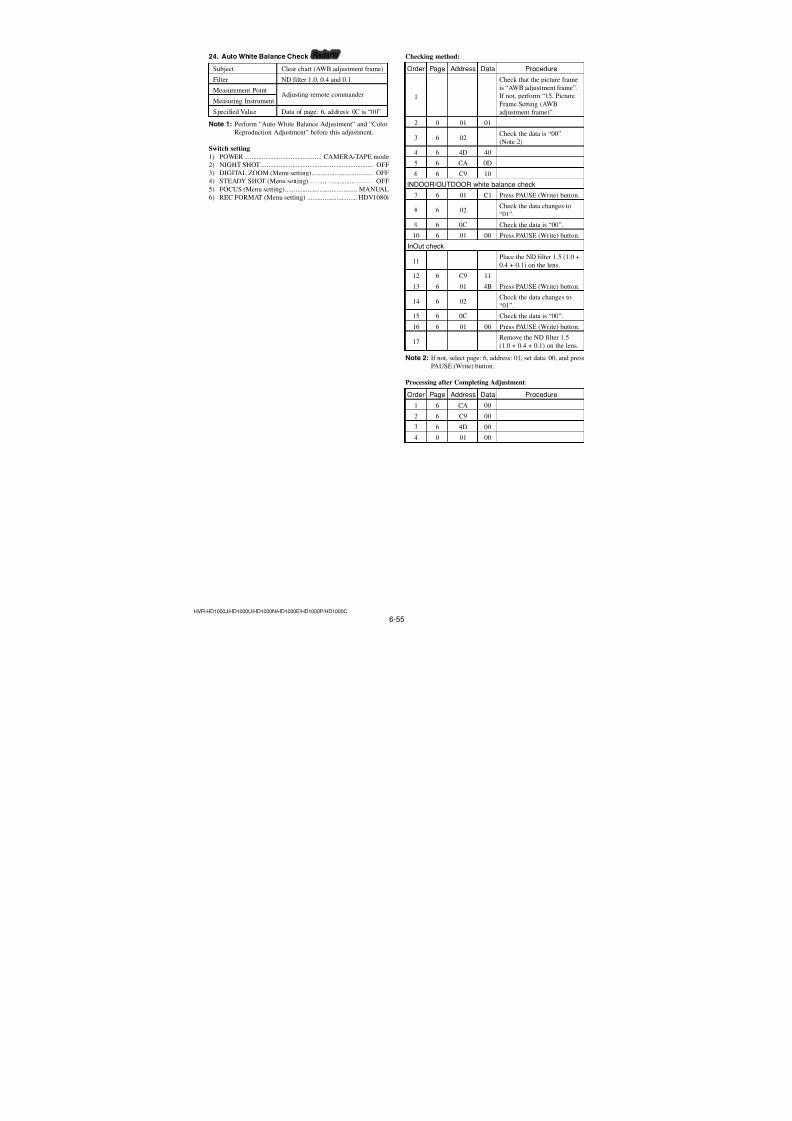
7/18/2019 SONY+HVR-HD1000 SERVICE MANUAL
http://slidepdf.com/reader/full/sonyhvr-hd1000-service-manual 187/4256-39HVR-HD1000J/HD1000U/HD1000N/HD1000E/HD1000P/HD1000C
8. Flange Back Check (Using the flange back adjustment jig)
Subject Flange back adjustment jig
(Luminance: approx. 200 lux)
Measurement PointCheck operation on monitor TV
Measuring Instrument
Specified value Focused at the TELE end and WIDE
end
Note: Check that the data of page: 0, address: 10 is “00”.
Switch setting
1) POWER ............................................. CAMERA-TAPE mode
2) NIGHT SHOT .................................................................. OFF
3) REC FORMAT (Menu setting) ............................. HDV1080i
Preparations before adjustments:
1) Install the flange back adjustment jig so that the distance be-
tween it and the front of lens of camera is less than 3 cm.
2) To open the IRIS, decrease the luminous intensity to the chart
of the flange back adjustment jig up to a point before noise
appear on the image. (approx. 200 lux)
3) Check that the center of chart meets the center of shot image
screen with the zoom lens at TELE end and WIDE end respec-tively.
Checking method:
Order Page Address Data Procedure
1 6 40 01
2 6 41 01
3 6 4D 40
4Shoot the chart with the
zoom TELE end.
5 6 2C 02
6Check that the lens is
focused.
7Shoot the chart with thezoom WIDE end.
8Check that the lens is
focused.
Processing after Completing Adjustment:
Order Page Address Data Procedure
1 6 2C 00
2 6 40 00
3 6 41 00
4 6 4D 00
9. Flange Back Check (Using the Siemens star)
Subject Siemens star
(2.0 m from the front of the lens)
(Luminance: approx. 200 lux)
Measurement PointCheck operation on monitor TV
Measuring Instrument
Specified value Focused at the TELE end and WIDE
end
Note 1: Check that the data of page: 0, address: 10 is “00”.
Switch setting
1) POWER ............................................. CAMERA-TAPE mode
2) NIGHT SHOT.................................................................. OFF
3) REC FORMAT (Menu setting) ............................. HDV1080i
Note 2: When the auto focus is ON, the lens can be checked if itis focused or not by observing the data on the page: 1 of
the adjusting remote commander.
1 : 00 : XX
Odd: Focused
Even: Unfocused
Preparations before adjustments:
1) Place the Siemens star 2.0 m from the front of the lens.
2) To open the IRIS, decrease the luminous intensity to the Si-
emens star up to a point before noise appear on the image.
Checking method:
Order Page Address Data Procedure
1 6 40 01
2 6 41 01
3 6 4D 40
4 Shoot the Siemens star with
the zoom TELE end.
5 Turn on the auto focus.
6 0 03 0F
7 1Check that the lens is
focused. (Note 2)
8 6 21 10
9 Shoot the Siemens star with
the zoom WIDE end.
10Observe the TV monitor and
check that the lens isfocused.
Processing after Completing Adjustment:
Order Page Address Data Procedure
1 6 21 00
2 6 40 00
3 6 41 00
4 6 4D 40
5 0 03 00
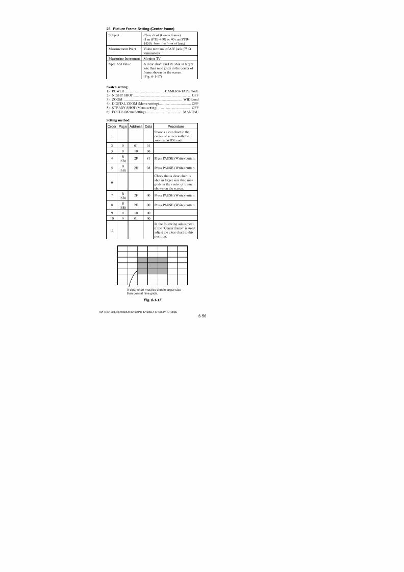
7/18/2019 SONY+HVR-HD1000 SERVICE MANUAL
http://slidepdf.com/reader/full/sonyhvr-hd1000-service-manual 188/4256-40HVR-HD1000J/HD1000U/HD1000N/HD1000E/HD1000P/HD1000C
11. Mechanical Shutter Adjustment (1) RadarW adarRadarW adarRadarW
Adjust the close time and loss time every F number of the me-chanical shutter and the high-speed shutter correction value to
correct the luminous exposure.
Adjustment Page 69
Adjustment Address A0 to B5
Note 1: If reading/writing data on pages 69 set data: 06 to page:
0, address: 10, and then select pages: 9. By this data set-
ting, the pages 69 can be selected.After the data reading/writing finished, return the data
on page: 0, address: 10 to “00”.
Adjusting method:
1) Select page: 0, address: 01, and set data: 01.
2) Select page: 0, address: 10, and set data: 06.
3) Input the following data to page: 9 (69), address: A0 to B5.Note 2: Press the PAUSE (Write) button of the adjustment re-
mote commander each time to set data.
AddressData
NTSC PAL
A0 0F 0C
A1 80 B0
A2 0B 09
A3 00 10
A4 08 07
A5 C0 20
A6 07 05
A7 00 A0
A8 05 04
A9 40 70
AA 54 55
AB 65 65
AC 63 64
AD 5C 5C
AE 4B 4B
AF 20 20
B0 80 80
B1 80 80
B2 80 80
B3 80 80B4 80 80
B5 80 80
4) Select page: 0, address: 10, and set data: 00.
5) Select page: 0, address: 01, and set data: 00.
10. F No. & ND Light Quality Standard Data Input
RadarW adarRadarW adarRadarW
Correct the lens iris and dispersion of the ND filter light quantity.
Adjustment Page 69
Adjustment Address E0 to EF
Note 1: If reading/writing data on pages 69, set data: 06 to page:0, address: 10, and then select pages: 9. By this data set-
ting, the pages 69 can be selected.
After the data reading/writing finished, return the data
on page: 0, address: 10 to “00”.
Adjusting method:
1) Select page: 0, address: 01, and set data: 01.
2) Select page: 0, address: 10, and set data: 06.
3) Input the following data to page: 69, address: E0 to EF.
Note 2: Press the PAUSE (Write) button of the adjustment re-
mote commander each time to set data.
Address
Data
NTSC PAL
E0 00 00
E1 00 00
E2 00 00
E3 00 00
E4 00 00
E5 00 00
E6 00 00
E7 00 00
E8 00 00
E9 00 00EA 00 00
EB 00 00
EC 00 00
ED 00 00
EE 00 00
EF 00 00
4) Select page: 0, address: 10, and set data: 00.
5) Select page: 0, address: 01, and set data: 00.
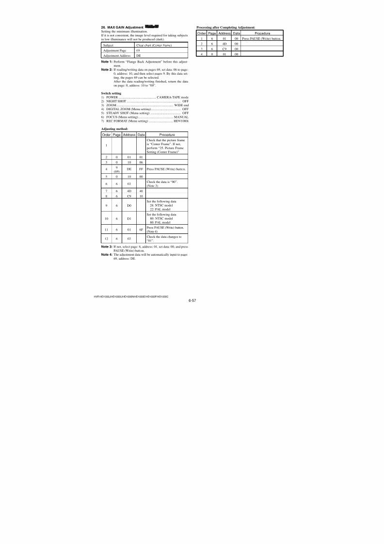
7/18/2019 SONY+HVR-HD1000 SERVICE MANUAL
http://slidepdf.com/reader/full/sonyhvr-hd1000-service-manual 189/4256-41HVR-HD1000J/HD1000U/HD1000N/HD1000E/HD1000P/HD1000C
12. Mechanical Shutter Adjustment (2) RadarW adarRadarW adarRadarW
Adjust the close time and loss time every F number of the me-chanical shutter and the high-speed shutter correction value to
correct the luminous exposure.
Adjustment Page 6F
Adjustment Address 7A to 7F
Note 1: If reading/writing data on pages 6F set data: 06 to page:
0, address: 10, and then select pages: F. By this data set-
ting, the pages 6F can be selected.After the data reading/writing finished, return the data
on page: 0, address: 10 to “00”.
Adjusting method:
1) Select page: 0, address: 01, and set data: 01.
2) Select page: 0, address: 10, and set data: 06.
3) Input the following data to page: F (6F), address: 7A to 7F.Note 2: Press the PAUSE (Write) button of the adjustment re-
mote commander each time to set data.
AddressData
NTSC PAL
7A 80 80
7B 80 80
7C 80 80
7D 80 80
7E 80 80
7F 80 80
4) Select page: 0, address: 10, and set data: 00.
5) Select page: 0, address: 01, and set data: 00.
13. Linear Matrix Adjustment (1) RadarW adarRadarW adarRadarW
Adjust the matrix coefficient for compensating the variation inspectral sensitivity.
Adjustment Page 69
Adjustment Address BE to CF
Note 1: If reading/writing data on pages 69, set data: 06 to page:0, address: 10, and then select pages: 9. By this data set-
ting, the pages 69 can be selected.
After the data reading/writing finished, return the dataon page: 0, address: 10 to “00”.
Adjusting method:
1) Select page: 0, address: 01, and set data: 01.
2) Select page: 0, address: 10, and set data: 06.
3) Input the following data to page: 9 (69), address: BE to CF.Note 2: Press the PAUSE (Write) button of the adjustment remote
commander each time to set data.
AddressData
NTSC PALBE 06 06
BF 8E 8E
C0 FE FE
C1 67 67
C2 00 00
C3 35 35
C4 FE FE
C5 F2 F2
C6 05 05
C7 A0 A0
C8 FE FE
C9 8A 8A
CA 00 00
CB 19 19
CC FE FE
CD 92 92
CE 06 06
CF 2A 2A
4) Select page: 0, address: 10, and set data: 00.
5) Select page: 0, address: 01, and set data: 00.
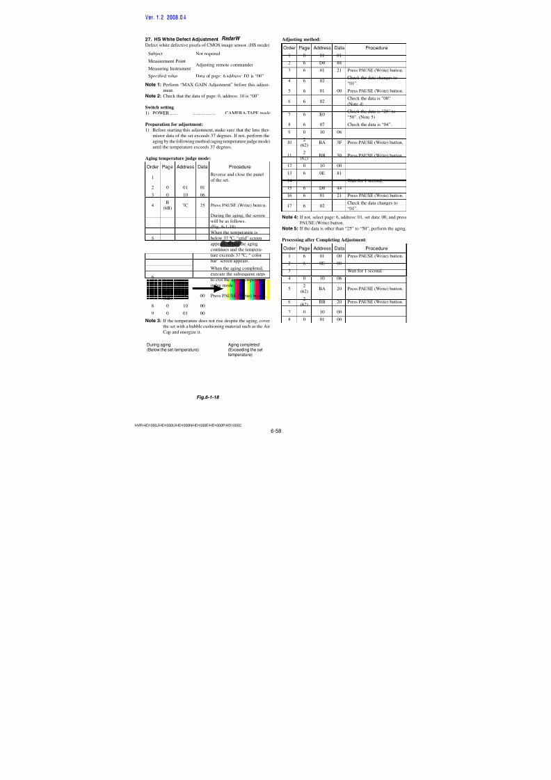
7/18/2019 SONY+HVR-HD1000 SERVICE MANUAL
http://slidepdf.com/reader/full/sonyhvr-hd1000-service-manual 190/4256-42HVR-HD1000J/HD1000U/HD1000N/HD1000E/HD1000P/HD1000C
14. Linear Matrix Adjustment (2) adaradarRadarW
Adjust the matrix coefficient for compensating the variation inspectral sensitivity.
Adjustment Page 6F
Adjustment Address 60 to 71, C8 to EB
Note 1: If reading/writing data on pages 6F, set data: 06 to page:0, address: 10, and then select pages: F. By this data set-
ting, the pages 6F can be selected.
After the data reading/writing finished, return the dataon page: 0, address: 10 to “00”.
Adjusting method:
1) Select page: 0, address: 01, and set data: 01.
2) Select page: 0, address: 10, and set data: 06.
3) Input the following data to page: F (6F), address: 60 to 71, C8
to EB.Note 2: Press the PAUSE (Write) button of the adjustment remote
commander each time to set data.
4) Select page: 0, address: 10, and set data: 00.
5) Select page: 0, address: 01, and set data: 00.
AddressData
NTSC PAL
60 21 21
61 78 78
62 02 02
63 BC BC
64 FE FE
65 34 34
66 FF FF
67 E9 E9
68 20 20
69 2D 2D
6A FF FF
6B AF AF
6C FF FF
6D 36 36
6E 05 05
6F 0A 0A
70 1D 1D
71 9D 9D
C8 03 03
C9 BF BFCA FF FF
CB A6 A6
CC 00 00
CD 32 32
CE 00 00
CF 0E 0E
D0 03 03
AddressData
NTSC PAL
D1 E5 E5
D2 00 00
D3 25 25
D4 00 00
D5 17 17
D6 FF FF
D7 55 55
D8 04 04
D9 7F 7F
DA 04 04
DB 45 45
DC 00 00
DD 5B 5B
DE FF FF
DF CE CE
E0 FF FF
E1 F3 F3
E2 04 04
E3 15 15
E4 FF FFE5 E0 E0
E6 FF FF
E7 E9 E9
E8 00 00
E9 9A 9A
EA 03 03
EB 8B 8B
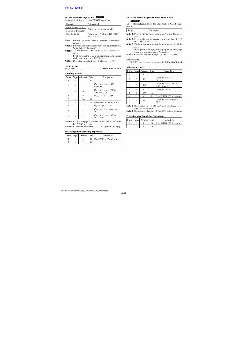
7/18/2019 SONY+HVR-HD1000 SERVICE MANUAL
http://slidepdf.com/reader/full/sonyhvr-hd1000-service-manual 191/4256-43HVR-HD1000J/HD1000U/HD1000N/HD1000E/HD1000P/HD1000C
15. Picture Frame Setting(AWB adjustment frame)
Subject Clear chart
(AWB adjustment frame)
(1 m (PTB-450) or 40 cm (PTB-
1450) from the front of lens)
Measurement Point Video terminal of A/V jack (75 Ω terminated)
Measuring Instrument Monitor TV (16:9)
Specified Value Only the clear chart must be shot(entire screen is white).
Note 1: Perform “Hall Adjustment” and “Flange Back Adjust-
ment” before this adjustment.
Note 2: Check that the data of page: 0, address: 10 is “00”.
Switch setting
1) POWER ............................................. CAMERA-TAPE mode
2) NIGHT SHOT .................................................................. OFF
3) DIGITAL ZOOM (Menu setting).................................... OFF
4) STEADY SHOT (Menu setting) ..................................... OFF
5) FOCUS (Menu Setting) ......................................... MANUAL
6) REC FORMAT (Menu setting) ............................. HDV1080i
Setting method:
Order Page Address Data Procedure
1 6 4D 40
2 Shoot the color bar chart.
3
Adjust the camera direction
and zoom to set a picture
frame so that color bars onthe chart can be shot on the
entire screen. (Refer to Fig.6-1-12)
4
Remove the color bar chartfrom the pattern box, and
install the clear chart.
5Check that whole of thescreen is white.
6
In the adjustment performed
later, when the “AWBadjustment frame” is used,
set the zoom and focus to this
position.
How to read the XH, XL, YH and YL data:
Order Page Address Data Procedure
1 0 03 18
2 1 Read XH data and XL data.
(Note 3)
3 0 03 22
4 1Read YH data and YL data.
(Note 3)
Note 3: The right four digits of the page: 1 displayed data of the
adjusting remote commander.
1:XX : XXXL or YL data
XH or YH data
How to reset the zoom and focus when they deviated:
If the zoom and focus deviated due to some reason, reset them inthe following method.
Order Page Address Data Procedure
1 6 4D 40
2 6 90 XL
3 6 91 XH
4 6 92 YL
5 6 93 YH
6 6 01 79 Press PAUSE (Write) button.
How to release the picture frame setting:
Order Page Address Data Procedure
1 6 4D 00
2 6 01 00 Press PAUSE (Write) button.
3 6 90 00
4 6 91 00
5 6 92 00
6 6 93 00
Check on the monitor TV (Underscanned mode)
Fig. 6-1-9
Color bar chart picture frame Monitor TV picture frame
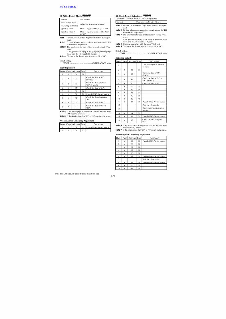
7/18/2019 SONY+HVR-HD1000 SERVICE MANUAL
http://slidepdf.com/reader/full/sonyhvr-hd1000-service-manual 192/4256-44HVR-HD1000J/HD1000U/HD1000N/HD1000E/HD1000P/HD1000C
16. Auto White Balance Standard Data Input RadarW adarRadarW adarRadarW
Adjust the white balance reference at 3200K, and adjust the nor-mal coefficient of the light value.
Subject Clear chart (AWB adjustment frame)
Adjustment Page 6F
Adjustment Address 88 to 97, F0 to F7
Note 1: Perform “F No. & ND Light Quality Standard Data In-
put” and “Linear Matrix Adjustment” before this adjust-
ment.
Note 2: If reading/writing data on pages 6F, set data: 06 to page:
0, address: 10, and then select pages: F. By this data set-
ting, the pages 6F can be selected.After the data reading/writing finished, return the data
on page: 0, address: 10 to “00”.
Switch setting
1) POWER ............................................. CAMERA-TAPE mode
2) NIGHT SHOT .................................................................. OFF
3) DIGITAL ZOOM (Menu setting).................................... OFF
4) STEADY SHOT (Menu setting) ..................................... OFF5) FOCUS (Menu setting).......................................... MANUAL
6) REC FORMAT (Menu setting) ............................. HDV1080i
Adjusting method:
Order Page Address Data Procedure
1
Check that the picture frame
is “AWB adjustment frame”.If not, perform “15. Picture
Frame Setting (AWB
adjustment frame)”
2 0 01 01
3 6 02 Check the data is “00”.(Note 3)
4 6 4D 40
5 6 CA 08
6 6 01 41Press PAUSE (Write) button.(Note 4)
7 6 02Check the data changes to
“01”.
Note 3: If not, select page: 6, address: 01, set data: 00, and press
PAUSE (Write) button.
Note 4: The adjustment data will be automatically input to page:
6F, address: 88 to 97, F0 to F7.
Processing after Completing Adjustment:
Order Page Address Data Procedure
1 6 01 00 Press PAUSE (Write) button.
2 6 CA 00
3 6 4D 00
4 0 01 00
17. LV Standard Data Input adaradarRadarW
Adjust the normal coefficient of the light value at 3200K.
Subject Clear chart (AWB adjustment frame)
Measuring Instrument Adjusting remote commander
Adjustment Page 69
Adjustment Address DC, DDSpecified Value Data of page: 6, address: 0C is “00”.
Note 1: Perform “F No. & ND Light Quality Standard Data In-
put” and “Auto White Balance Standard Data Input” be-
fore this adjustment.Note 2: If reading/writing data on pages 69, set data: 06 to page:
0, address: 10, and then select pages 9. By this data set-
ting, the pages 69 can be selected.
After the data reading/writing finished, return the data
on page: 0, address: 10 to “00”.
Switch setting
1) POWER ............................................. CAMERA-TAPE mode
2) NIGHT SHOT.................................................................. OFF3) DIGITAL ZOOM (Menu setting).................................... OFF
4) STEADY SHOT (Menu setting) ..................................... OFF
5) FOCUS (Menu setting).......................................... MANUAL
6) REC FORMAT (Menu setting) ............................. HDV1080i
Adjusting method:
Order Page Address Data Procedure
1
Check that the picture frameis “AWB adjustment frame”.
If not, perform “15. Picture
Frame Setting (AWB
adjustment frame)”
2 0 01 01
3 6 02Check the data is “00”.(Note 3)
4 6 4D 40
5 6 C9 10
6 6 01 0DPress PAUSE (Write) button.
(Note 4)
7 6 02Check the data changes to“01”.
8 6 0C Check the data is “00”.
Note 3: If not, select page: 6, address: 01, set data: 00, and press
PAUSE (Write) button.Note 4: The adjustment data will be automatically input to page:
69, address: DC, DD.
Processing after Completing Adjustment:
Order Page Address Data Procedure
1 6 01 00 Press PAUSE (Write) button.
2 6 C9 00
3 6 4D 00
4 0 01 00
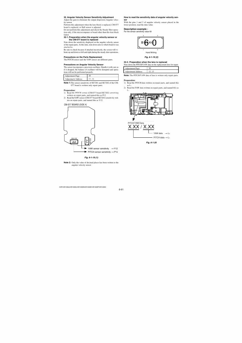
7/18/2019 SONY+HVR-HD1000 SERVICE MANUAL
http://slidepdf.com/reader/full/sonyhvr-hd1000-service-manual 193/4256-45HVR-HD1000J/HD1000U/HD1000N/HD1000E/HD1000P/HD1000C
18. Auto White Balance Adjustment RadarW adarRadarW adarRadarW
Adjust to the proper auto white balance output data.If it is not correct, auto white balance and color reproducibility
will be poor.
Subject Clear chart (AWB adjustment frame)
Filter Filter C14 for color temperature
correction
Adjustment Page 6F
Adjustment Address 84 to 87, 98 to A7, F8 to FF
Note 1: Perform “F No. & ND Light Quality Standard Data In-
put” and “Auto White Balance Standard Data Input” be-
fore this adjustment.
Note 2: If reading/writing data on pages 6F, set data: 06 to page:
0, address: 10, and then select pages: F. By this data set-ting, the pages 6F can be selected.
After the data reading/writing finished, return the data
on page: 0, address: 10 to “00”.
Switch setting
1) POWER ............................................. CAMERA-TAPE mode
2) NIGHT SHOT .................................................................. OFF
3) DIGITAL ZOOM (Menu setting).................................... OFF4) STEADY SHOT (Menu setting) ..................................... OFF
5) FOCUS (Menu setting).......................................... MANUAL
6) REC FORMAT (Menu setting) ............................. HDV1080i
Adjusting method:
Order Page Address Data Procedure
1
Check that the picture frame
is “AWB adjustment frame”.If not, perform “15. Picture
Frame Setting (AWB
adjustment frame)”
2Place the C14 filter on the
lens.
3 0 01 01
4 6 02Check the data is “00”.
(Note 3)
5 6 4D 40
6 6 CA 08
7 0 10 06
8F
84 2A Press PAUSE (Write) button.(6F)
9 F 85 80 Press PAUSE (Write) button.(6F)
10F
86 5E Press PAUSE (Write) button.(6F)
11F
87 40 Press PAUSE (Write) button.(6F)
12 0 10 00
13 6 01 45Press PAUSE (Write) button.
(Note 4)
14 6 02Check the data changes to
“01”.
Note 3: If not, select page: 6, address: 01, set data: 00, and press
PAUSE (Write) button.Note 4: The adjustment data will be automatically input to page:
6F, address: 98 to A7, F8 to FF.
Processing after Completing Adjustment:
Order Page Address Data Procedure
1 6 01 00 Press PAUSE (Write) button.
2 6 CA 00
3 6 4D 00
4 0 01 00
5Remove the C14 filter on the
lens.
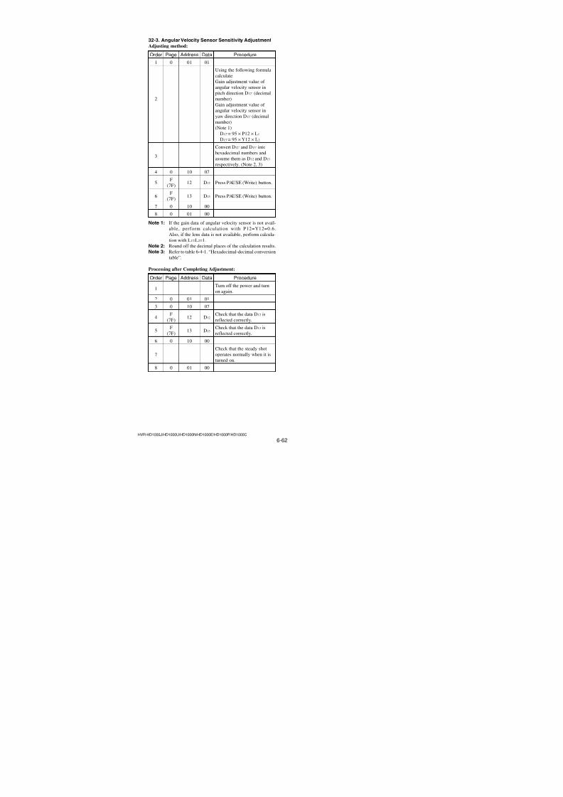
7/18/2019 SONY+HVR-HD1000 SERVICE MANUAL
http://slidepdf.com/reader/full/sonyhvr-hd1000-service-manual 194/4256-46HVR-HD1000J/HD1000U/HD1000N/HD1000E/HD1000P/HD1000C
How to reset the zoom and focus when they deviated:
If the zoom and focus deviated due to some reason, reset them inthe following method.
Order Page Address Data Procedure
1 6 4D 40
2 6 90 XL
3 6 91 XH
4 6 92 YL
5 6 93 YH
6 6 01 79 Press PAUSE (Write) button.
How to release the picture frame setting:
Order Page Address Data Procedure
1 6 4D 00
2 6 01 00 Press PAUSE (Write) button.
3 6 90 00
4 6 91 00
5 6 92 00
6 6 93 00
Check on the oscilloscope1. Horizontal period
Fig. 6-1-10
2. Vertical period
Fig. 6-1-11
Check on the monitor TV (Underscanned mode)
Fig. 6-1-12
19. Picture Frame Setting(Color reproduction adjustment frame)
Subject Color bar chart
(Color reproduction adjustment
frame)
(1 m (PTB-450) or 40 cm (PTB-
1450) from the front of lens)Measurement Point Video terminal of A/V jack
(75 Ω terminated)
Measuring Instrument Oscilloscope and monitor TV (16:9)
Specified Value A = B, C = D, E = F
Note 1: Perform “Hall Adjustment” and “Flange Back Adjust-
ment” before this adjustment.
Note 2: Check that the data of page: 0, address: 10 is “00”.
Switch setting
1) POWER ............................................. CAMERA-TAPE mode
2) NIGHT SHOT .................................................................. OFF
3) DIGITAL ZOOM (Menu setting).................................... OFF
4) STEADY SHOT (Menu setting) ..................................... OFF
5) FOCUS (Menu Setting) ......................................... MANUAL
6) REC FORMAT (Menu setting) ............................. HDV1080i
Setting method:
Order Page Address Data Procedure
1 6 4D 40
2Adjust the zoom and thecamera direction, and set the
specified position.
3
Mark the position of thepicture frame on the monitor
TV, and adjust the pictureframe to this position in
following adjustment using
“Color reproduction
adjustment frame”.
How to read the XH, XL, YH and YL data:
Order Page Address Data Procedure
1 0 03 18
2 1 Read XH data and XL data.
(Note 3)
3 0 03 22
4 1Read YH data and YL data.
(Note 3)
Note 3: The right four digits of the page: 1 displayed data of the
adjusting remote commander.
1:XX : XX
XL or YL data
XH or YH data
H
A = B C = D
A B C D
E = F = 0
V
E F
Color bar chart picture frame Monitor TV picture frame
A = B
E = F = 0
C = DA B
E
F
C D
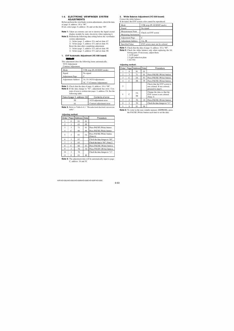
7/18/2019 SONY+HVR-HD1000 SERVICE MANUAL
http://slidepdf.com/reader/full/sonyhvr-hd1000-service-manual 195/4256-47HVR-HD1000J/HD1000U/HD1000N/HD1000E/HD1000P/HD1000C
20. Color Reproduction Adjustment & Check
(Indoor HD) adaradarRadarW
Adjust the color separation matrix coefficient so that proper color
reproduction is produced.
Subject Color bar chart(Color reproduction adjustment
frame)
Measurement Point Video reminal of A/V jack (75 Ω terminated)
Measuring Instrument Vectorscope, Oscilloscope
Adjustment Page 6F
Adjustment Address A8 to B7
Specified Value All color luminance points should
settle within each color reproductionframe.
Note 1: Perform “F No. & ND Light Quality Standard Data In-
put” and “Auto White Balance Standard Data Input” be-
fore this adjustment.Note 2: If reading/writing data on pages 6F, set data: 06 to page:0, address: 10, and then select pages: F. By this data set-
ting, the pages 6F can be selected.
After the data reading/writing finished, return the data
on page: 0, address: 10 to “00”.
Switch setting
1) POWER ............................................. CAMERA-TAPE mode
2) NIGHT SHOT .................................................................. OFF3) DIGITAL ZOOM (Menu setting).................................... OFF
4) STEADY SHOT (Menu setting) ..................................... OFF
5) FOCUS (Menu setting).......................................... MANUAL
6) REC FORMAT (Menu setting) ............................. HDV1080i
Fig. 6-1-13
R-Y
B-Y
R
G
B
CY
YE
MG
Burst position
R-Y
B-Y
R
G
B
CY
YE
MG
Burst position
PAL model
NTSC model
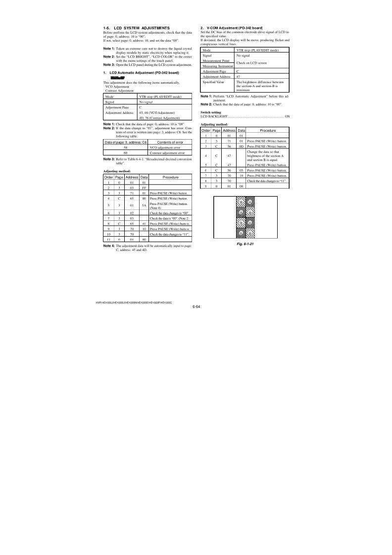
7/18/2019 SONY+HVR-HD1000 SERVICE MANUAL
http://slidepdf.com/reader/full/sonyhvr-hd1000-service-manual 196/4256-48HVR-HD1000J/HD1000U/HD1000N/HD1000E/HD1000P/HD1000C
Adjusting method:
Order Page Address Data Procedure
1
Check that the picture frame
is “Color ReproductionAdjustment Frame”. If not,
Perform “19. Picture Frame
Setting (Color ReproductionAdjustment Frame)”.
2 0 01 01
3 7 01 BD
4 7 00 01 Press PAUSE (Write) button.
5 6 9BCheck the bit value of bit 2, 3
is “0”. (Note 3)
6 6 02Check the data is “00”.
(Note 4)
7 6 4D 40
8 6 C9 10
9 6 CA 0C10 6 D0 59
11 6 01 61Press PAUSE (Write) button.
(Note 5)
12 6 02Check the data changes to
“01”.
13 6 0C Check the data is “00”.
14
Adjust the GAIN and
PHASE of the verctorscope,
and set to the burst lumi-
nance point to the burst
position of color reproduc-
tion frame.
15
Check the each color
luminance point is in each
color reproduction frame.
Note 3: For the bit values, refer to “6-4. SERVICE MODE”, ”4-
4.3. Bit value discrimitaion”.
Note 4: If not, select page: 6, address: 01, set data: 00, and press
PAUSE (Write) button.Note 5: The adjustment data will be automatically input to page:
6F, address: A8 to B7.
Processing after Completing Adjustment:
Order Page Address Data Procedure
1 6 01 00 Press PAUSE (Write) button.
2 6 4D 00
3 6 C9 00
4 6 CA 00
5 6 D0 00
6 0 01 00
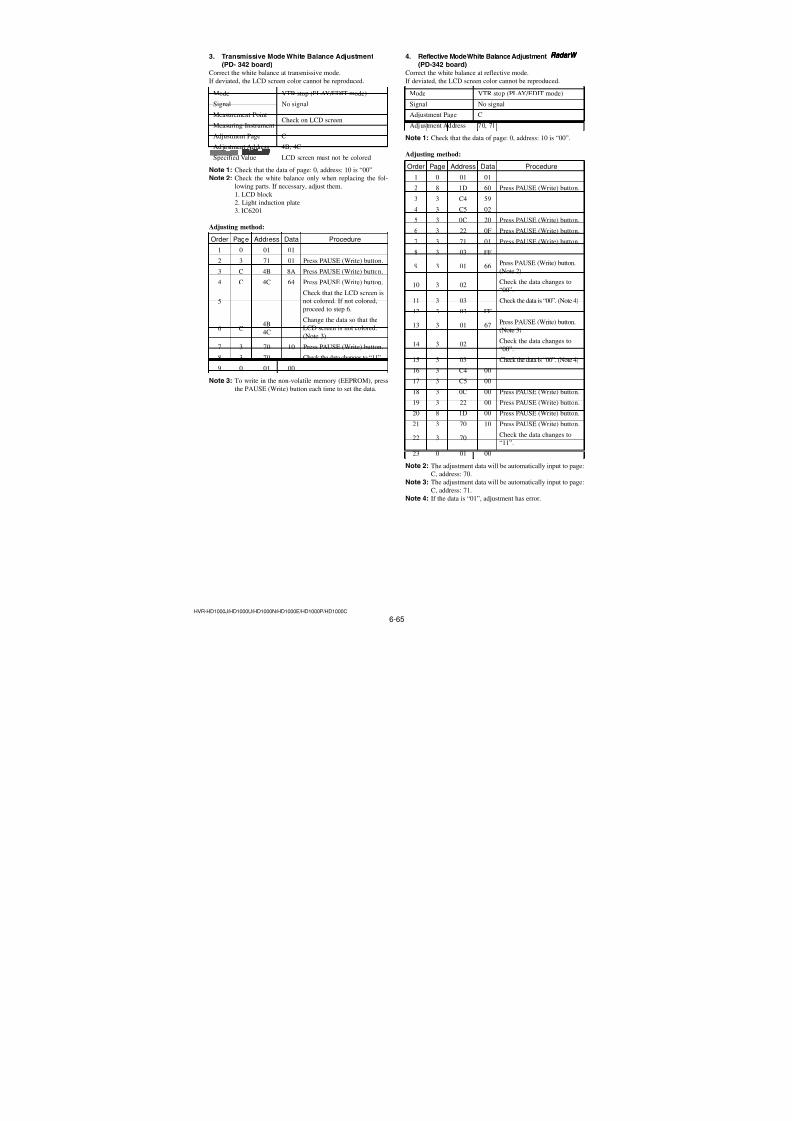
7/18/2019 SONY+HVR-HD1000 SERVICE MANUAL
http://slidepdf.com/reader/full/sonyhvr-hd1000-service-manual 197/4256-49HVR-HD1000J/HD1000U/HD1000N/HD1000E/HD1000P/HD1000C
21. Color Reproduction Check (Indoor SD) RadarW adarRadarW adarRadarW
Subject Color bar chart (Color reproduction
adjustment frame)
Measurement Point Video terminal of Adjusting
A/V jack remote
(75 Ω terminated) commander
Measuring Instrument Vectorscope
Specified Value All color Data of page: 6,
luminance address: 0C is
points should “00”.settle within each
color
reproduction
frame.
Note 1: Perform “Color Reproduction Adjustment” before this
adjustment.
Note 2: Check that the data of page: 0, address: 10 is “00”.
Switch setting
1) POWER ............................................. CAMERA-TAPE mode
2) NIGHT SHOT .................................................................. OFF
3) DIGITAL ZOOM (Menu setting).................................... OFF4) STEADY SHOT (Menu setting) ..................................... OFF
5) FOCUS (Menu setting).......................................... MANUAL
NTSC model
PAL model
Fig. 6-1-14
R-Y
B-Y
R
G
B
CY
YE
MG
Burst position
R-Y
B-Y
R
G
B
CY
YE
MG
Burst position
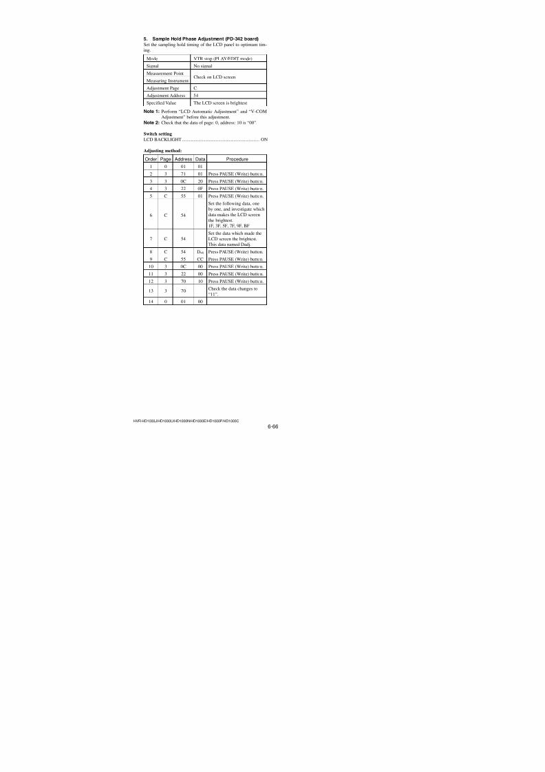
7/18/2019 SONY+HVR-HD1000 SERVICE MANUAL
http://slidepdf.com/reader/full/sonyhvr-hd1000-service-manual 198/4256-50HVR-HD1000J/HD1000U/HD1000N/HD1000E/HD1000P/HD1000C
Adjusting method:
Order Page Address Data Procedure
1
Check that the picture frame
is “Color ReproductionAdjustment Frame”. If not,
Perform “19. Picture Frame
Setting (Color ReproductionAdjustment Frame)”.
2 0 01 01
3 7 01 BE
4 7 00 01 Press PAUSE (Write) button.
5 6 9B
Check the bit value of bit 2 is
“1”. (Note 3)
Check the bit value of bit 3 is
“0”. (Note 3)
6 6 02Check the data is “00”.
(Note 4)
7 6 4D 40
8 6 C9 10
9 6 CA 0C
10 6 D0 59
11 6 01 4D Press PAUSE (Write) button.
12 6 02Check the data changes to
“01”.
13 6 0C Check the data is “00”.
14
Adjust the GAIN andPHASE of the vectorscope,
and set to the burst luminance
point to the burst position of
color reproduction frame.
15
Check that the each color
luminance point is in each
color reproduction frame.
Note 3: For the bit values, refer to “6-4. SERVICE MODE”, “4-
4. 3. Bit value discrimination”.Note 4: If not, select page: 6, address: 01, set data: 00, and press
PAUSE (Write) button.
Processing after Completing Adjustment:
Order Page Address Data Procedure
1 6 01 00 Press PAUSE (Write) button.
2 6 4D 00
3 6 C9 00
4 6 CA 005 6 D0 00
6 7 01 BD
7 7 00 01 Press PAUSE (Write) button.
8 0 01 00
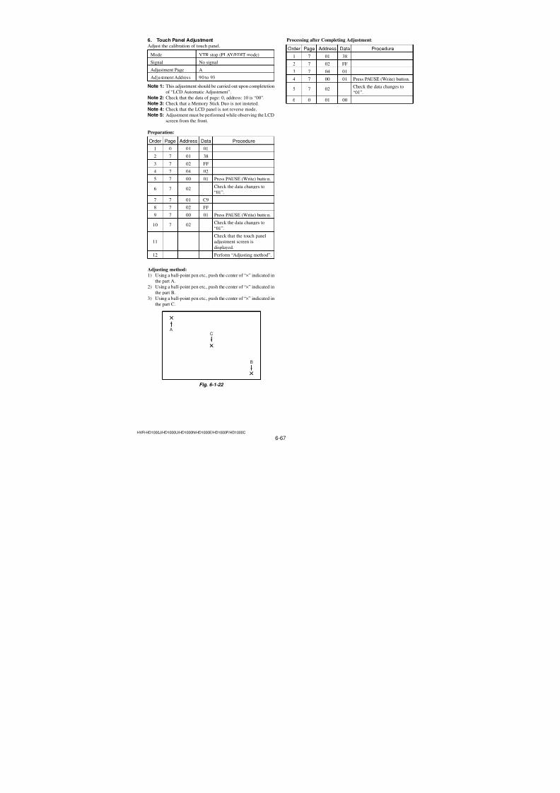
7/18/2019 SONY+HVR-HD1000 SERVICE MANUAL
http://slidepdf.com/reader/full/sonyhvr-hd1000-service-manual 199/4256-51HVR-HD1000J/HD1000U/HD1000N/HD1000E/HD1000P/HD1000C
22. Color Reproduction Check (Outdoor HD)adaradarRadarW
SubjectColor bar chart (Color reproduction
adjustment frame)
Filter Filter C14 for color temperature
correction
Measurement Point Video terminal of AdjustingA/V jack remote
(75 Ω terminated) commander
Measuring Instrument Vectorscope
Specified Value All color Data of page: 6,
luminance address: 0C is
points should “00”.
settle within eachcolor
reproduction
frame.
Note 1: Perform “Color Reproduction Adjustment” before this
adjustment.
Note 2: Check that the data of page: 0, address: 10 is “00”.
Switch setting
1) POWER ............................................. CAMERA-TAPE mode
2) NIGHT SHOT .................................................................. OFF
3) DIGITAL ZOOM (Menu setting).................................... OFF
4) STEADY SHOT (Menu setting) ..................................... OFF
5) FOCUS (Menu setting).......................................... MANUAL6) REC FORMAT (Menu setting) ............................. HDV1080i
NTSC model
PAL model
Fig. 6-1-15
Burst position
R-Y
B-Y
R
G
B
MG
CY
YE
R-Y
B-Y
R
G
B
MG
CY
YE
Burst position
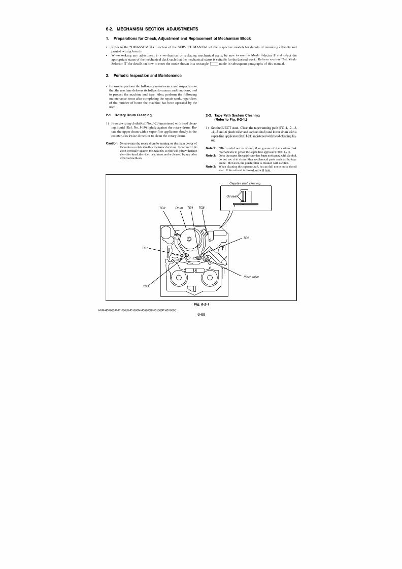
7/18/2019 SONY+HVR-HD1000 SERVICE MANUAL
http://slidepdf.com/reader/full/sonyhvr-hd1000-service-manual 200/4256-52HVR-HD1000J/HD1000U/HD1000N/HD1000E/HD1000P/HD1000C
Adjusting method:
Order Page Address Data Procedure
1
Check that the picture frame
is “Color ReproductionAdjustment Frame”. If not,
Perform “19. Picture Frame
Setting (Color ReproductionAdjustment Frame)”.
2Place the C14 filter on the
lens.
3 0 01 01
4 7 01 BD
5 7 00 01 Press PAUSE (Write) button.
6 6 9BCheck the bit value of bit 2, 3
is “0”. (Note 3)
7 6 02Check the data is “00”.
(Note 4)
8 6 4D 40
9 6 C9 10
10 6 CA 0C
11 6 D0 59
12 6 01 3D Press PAUSE (Write) button.
13 6 02Check the data changes to
“01”.
14 6 0C Check the data is “00”.
15
Adjust the GAIN andPHASE of the vectorscope,
and set to the burst luminance
point to the burst
position of color reproduction frame.
16
Check that the each color
luminance point is in each
color reproduction frame.
Note 3: For the bit values, refer to “6-4. SERVICE MODE”, “4-
4. 3. Bit value discrimination”.Note 4: If not, select page: 6, address: 01, set data: 00, and press
PAUSE (Write) button.
Processing after Completing Adjustment:
Order Page Address Data Procedure
1 6 01 00 Press PAUSE (Write) button.
2 6 4D 00
3 6 C9 00
4 6 CA 005 6 D0 00
6 0 01 00
7Remove the C14 filter on the
lens.
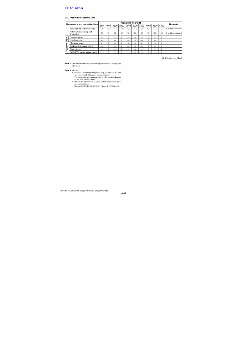
7/18/2019 SONY+HVR-HD1000 SERVICE MANUAL
http://slidepdf.com/reader/full/sonyhvr-hd1000-service-manual 201/4256-53HVR-HD1000J/HD1000U/HD1000N/HD1000E/HD1000P/HD1000C
23. Color Reproduction Check (Outdoor SD) RadarW adarRadarW adarRadarW
Subject Color bar chart (Color reproduction
adjustment frame)
Filter Filter C14 for color temperature
correction
Measurement Point Video terminal of AdjustingA/V jack remote
(75 Ω terminated) commander
Measuring Instrument Vectorscope
Specified Value All color Data of page: 6,
luminance address: 0C is
points should “00”
settle within eachcolor
reproduction
frame.
Note 1: Perform “Color Reproduction Adjustment” before this
adjustment.
Note 2: Check that the data of page: 0, address: 10 is “00”.
Switch setting
1) POWER ............................................. CAMERA-TAPE mode
2) NIGHT SHOT .................................................................. OFF
3) DIGITAL ZOOM (Menu setting).................................... OFF
4) STEADY SHOT (Menu setting) ..................................... OFF
5) FOCUS (Menu setting).......................................... MANUAL
NTSC model
PAL model
Fig. 6-1-16
Burst position
R-Y
B-Y
R
G
B
MG
CY
YE
R-Y
B-Y
R
G
B
MG
CY
YE
Burst position
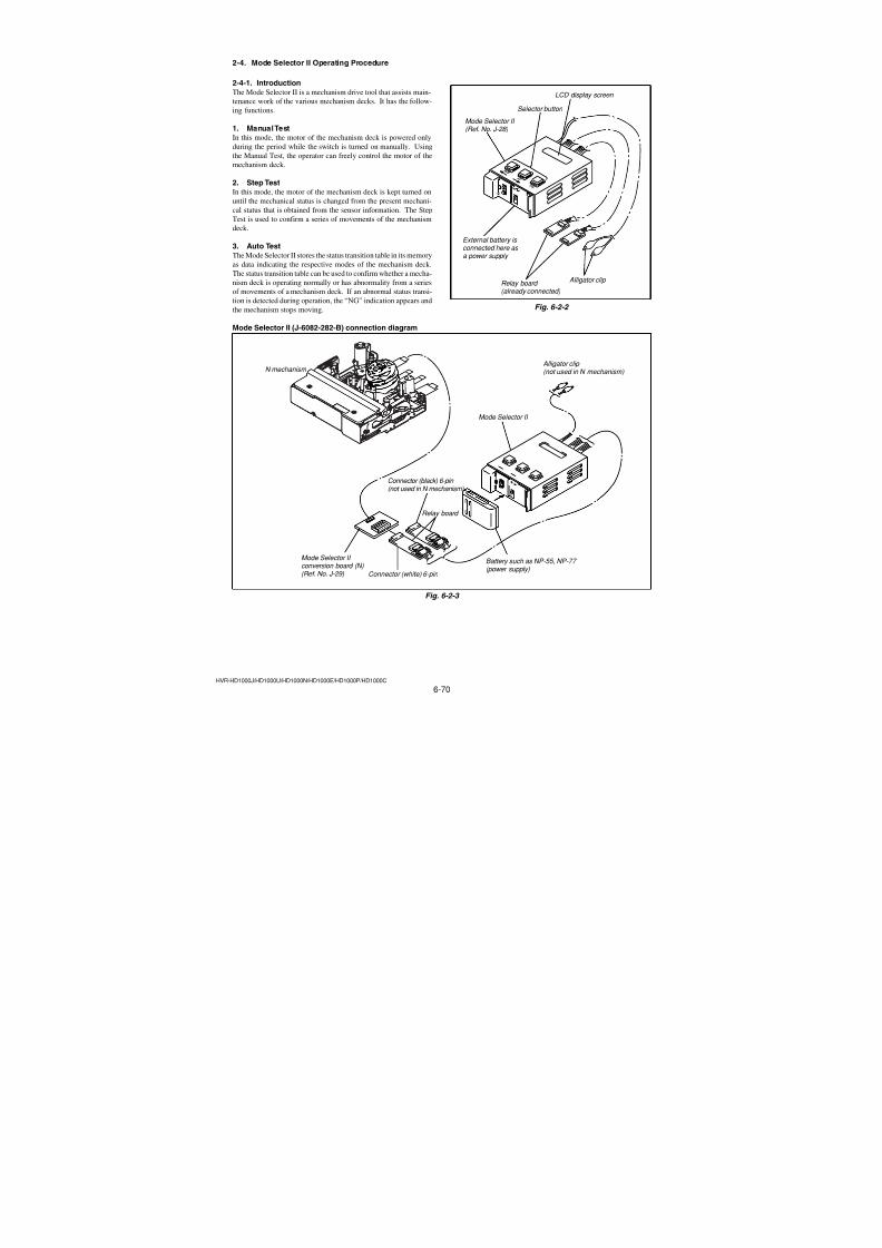
7/18/2019 SONY+HVR-HD1000 SERVICE MANUAL
http://slidepdf.com/reader/full/sonyhvr-hd1000-service-manual 202/4256-54HVR-HD1000J/HD1000U/HD1000N/HD1000E/HD1000P/HD1000C
Adjusting method:
Order Page Address Data Procedure
1
Check that the picture frame
is “Color ReproductionAdjustment Frame”. If not,
Perform “19. Picture Frame
Setting (Color ReproductionAdjustment Frame)”.
2Place the C14 filter on the
lens.
3 0 01 01
4 7 01 BE
5 7 00 01 Press PAUSE (Write) button.
6 6 9B
Check the bit value of bit 2 is
“1”. (Note 3)
Check the bit value of bit 3 is
“0”. (Note 3)
7 6 02Check the data is “00”.
(Note 4)
8 6 4D 40
9 6 C9 10
10 6 CA 0C
11 6 D0 59
12 6 01 3D Press PAUSE (Write) button.
13 6 02Check the data changes to
“01”.
14 6 0C Check the data is “00”.
15
Adjust the GAIN and
PHASE of the vectorscope,
and set to the burst luminancepoint to the burst position of
color reproduction frame.
16
Check that the each colorluminance point is in each
color reproduction frame.
Note 3: For the bit values, refer to “6-4. SERVICE MODE”, “4-
4. 3. Bit value discrimination”.Note 4: If not, select page: 6, address: 01, set data: 00, and press
PAUSE (Write) button.
Processing after Completing Adjustment:
Order Page Address Data Procedure
1 6 01 00 Press PAUSE (Write) button.
2 6 4D 00
3 6 C9 00
4 6 CA 005 6 D0 00
6 7 01 BD
7 7 00 01 Press PAUSE (Write) button.
8 0 01 00
9Remove the C14 filter on the
lens.
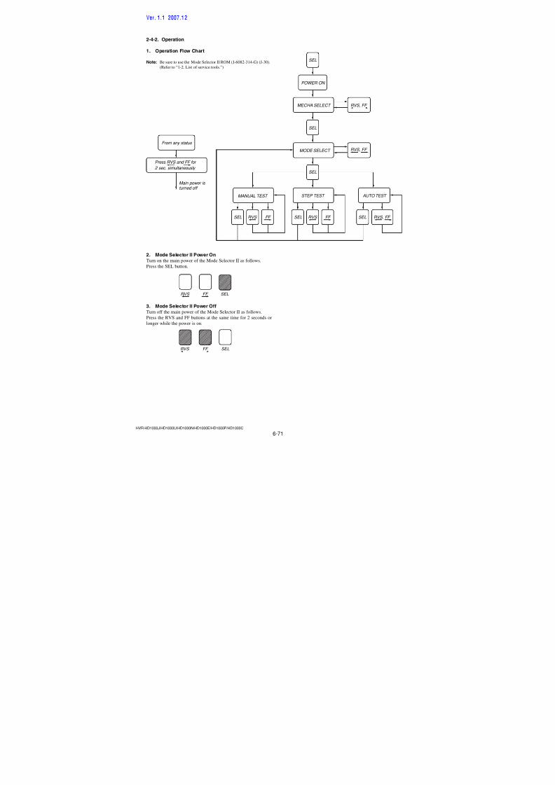
7/18/2019 SONY+HVR-HD1000 SERVICE MANUAL
http://slidepdf.com/reader/full/sonyhvr-hd1000-service-manual 203/4256-55HVR-HD1000J/HD1000U/HD1000N/HD1000E/HD1000P/HD1000C
24. Auto White Balance Check adaradarRadarW
Subject Clear chart (AWB adjustment frame)
Filter ND filter 1.0, 0.4 and 0.1
Measurement PointAdjusting remote commander
Measuring Instrument
Specified Value Data of page: 6, address: 0C is “00”
Note 1: Perform “Auto White Balance Adjustment” and “Color
Reproduction Adjustment” before this adjustment.
Switch setting
1) POWER ............................................. CAMERA-TAPE mode2) NIGHT SHOT .................................................................. OFF
3) DIGITAL ZOOM (Menu setting).................................... OFF
4) STEADY SHOT (Menu setting) ..................................... OFF
5) FOCUS (Menu setting).......................................... MANUAL
6) REC FORMAT (Menu setting) ............................. HDV1080i
Checking method:
Order Page Address Data Procedure
1
Check that the picture frame
is “AWB adjustment frame”.If not, perform “15. Picture
Frame Setting (AWB
adjustment frame)”.
2 0 01 01
3 6 02Check the data is “00”.
(Note 2)
4 6 4D 40
5 6 CA 0D
6 6 C9 10
INDOOR/OUTDOOR white balance check
7 6 01 C1 Press PAUSE (Write) button.
8 6 02Check the data changes to
“01”.
9 6 0C Check the data is “00”.
10 6 01 00 Press PAUSE (Write) button.
InOut check
11Place the ND filter 1.5 (1.0 +
0.4 + 0.1) on the lens.
12 6 C9 11
13 6 01 4B Press PAUSE (Write) button.
14 6 02Check the data changes to
“01”.
15 6 0C Check the data is “00”.
16 6 01 00 Press PAUSE (Write) button.
17 Remove the ND filter 1.5(1.0 + 0.4 + 0.1) on the lens.
Note 2: If not, select page: 6, address: 01, set data: 00, and press
PAUSE (Write) button.
Processing after Completing Adjustment:
Order Page Address Data Procedure
1 6 CA 00
2 6 C9 00
3 6 4D 00
4 0 01 00
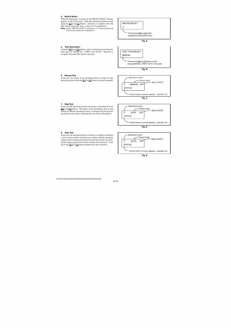
7/18/2019 SONY+HVR-HD1000 SERVICE MANUAL
http://slidepdf.com/reader/full/sonyhvr-hd1000-service-manual 204/4256-56HVR-HD1000J/HD1000U/HD1000N/HD1000E/HD1000P/HD1000C
25. Picture Frame Setting (Center frame)
Subject Clear chart (Center frame)
(1 m (PTB-450) or 40 cm (PTB-
1450) from the front of lens)
Measurement Point Video terminal of A/V jack (75 Ω
terminated)
Measuring Instrument Monitor TV
Specified Value A clear chart must be shot in larger
size than nine grids in the center of
frame shown on the screen.(Fig. 6-1-17)
Switch setting
1) POWER ............................................. CAMERA-TAPE mode
2) NIGHT SHOT .................................................................. OFF
3) ZOOM .................................................................... WIDE end4) DIGITAL ZOOM (Menu setting).................................... OFF
5) STEADY SHOT (Menu setting) ..................................... OFF
6) FOCUS (Menu Setting) ......................................... MANUAL
Setting method:
Order Page Address Data Procedure
1
Shoot a clear chart in the
center of screen with thezoom at WIDE end.
2 0 01 01
3 0 10 06
4B
2F 81 Press PAUSE (Write) button.(6B)
5 B 2E 08 Press PAUSE (Write) button.
(6B)
6
Check that a clear chart is
shot in larger size than ninegrids in the center of frame
shown on the screen.
7 B 2F 00 Press PAUSE (Write) button.(6B)
8 B 2E 00 Press PAUSE (Write) button.(6B)
9 0 10 00
10 0 01 00
11
In the following adjustment,
if the “Center frame” is used,adjust the clear chart to this
position.
Fig. 6-1-17
A clear chart must be shot in larger sizethan central nine grids.
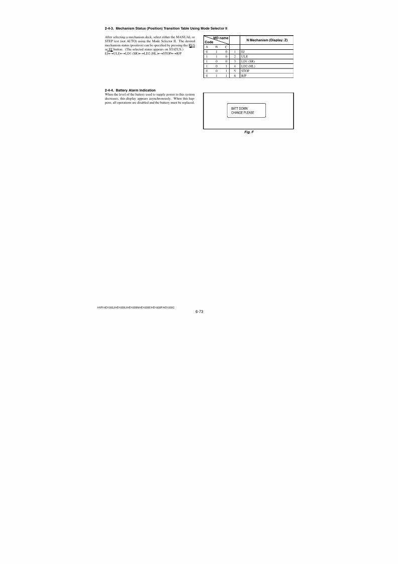
7/18/2019 SONY+HVR-HD1000 SERVICE MANUAL
http://slidepdf.com/reader/full/sonyhvr-hd1000-service-manual 205/4256-57HVR-HD1000J/HD1000U/HD1000N/HD1000E/HD1000P/HD1000C
Processing after Completing Adjustment:
Order Page Address Data Procedure
1 6 01 00 Press PAUSE (Write) button.
2 6 4D 00
3 6 C9 00
4 0 01 00
26. MAX GAIN Adjustment RadarW adarRadarW adarRadarW
Setting the minimum illumination.If it is not consistent, the image level required for taking subjects
in low illuminance will not be produced (dark).
Subject Clear chart (Center frame)
Adjustment Page 69
Adjustment Address DE
Note 1: Perform “Flange Back Adjustment” before this adjust-
ment.
Note 2: If reading/writing data on pages 69, set data: 06 to page:
0, address: 10, and then select pages 9. By this data set-
ting, the pages 69 can be selected.After the data reading/writing finished, return the data
on page: 0, address: 10 to “00”.
Switch setting
1) POWER ............................................. CAMERA-TAPE mode
2) NIGHT SHOT .................................................................. OFF
3) ZOOM .................................................................... WIDE end
4) DIGITAL ZOOM (Menu setting).................................... OFF5) STEADY SHOT (Menu setting) ..................................... OFF
6) FOCUS (Menu setting).......................................... MANUAL
7) REC FORMAT (Menu setting) ............................. HDV1080i
Adjusting method:
Order Page Address Data Procedure
1
Check that the picture frameis “Center Frame”. If not,
perform “25. Picture Frame
Setting (Center Frame)”
2 0 01 01
3 0 10 06
4 9 DE FF Press PAUSE (Write) button.(69)
5 0 10 00
6 6 02Check the data is “00”.(Note 3)
7 6 4D 40
8 6 C9 10
9 6 D0
Set the following data
28: NTSC model
22: PAL model
10 6 D1
Set the following data
80: NTSC model80: PAL model
11 6 01 6FPress PAUSE (Write) button.
(Note 4)
12 6 02Check the data changes to“01”.
Note 3: If not, select page: 6, address: 01, set data: 00, and press
PAUSE (Write) button.
Note 4: The adjustment data will be automatically input to page:
69, address: DE.
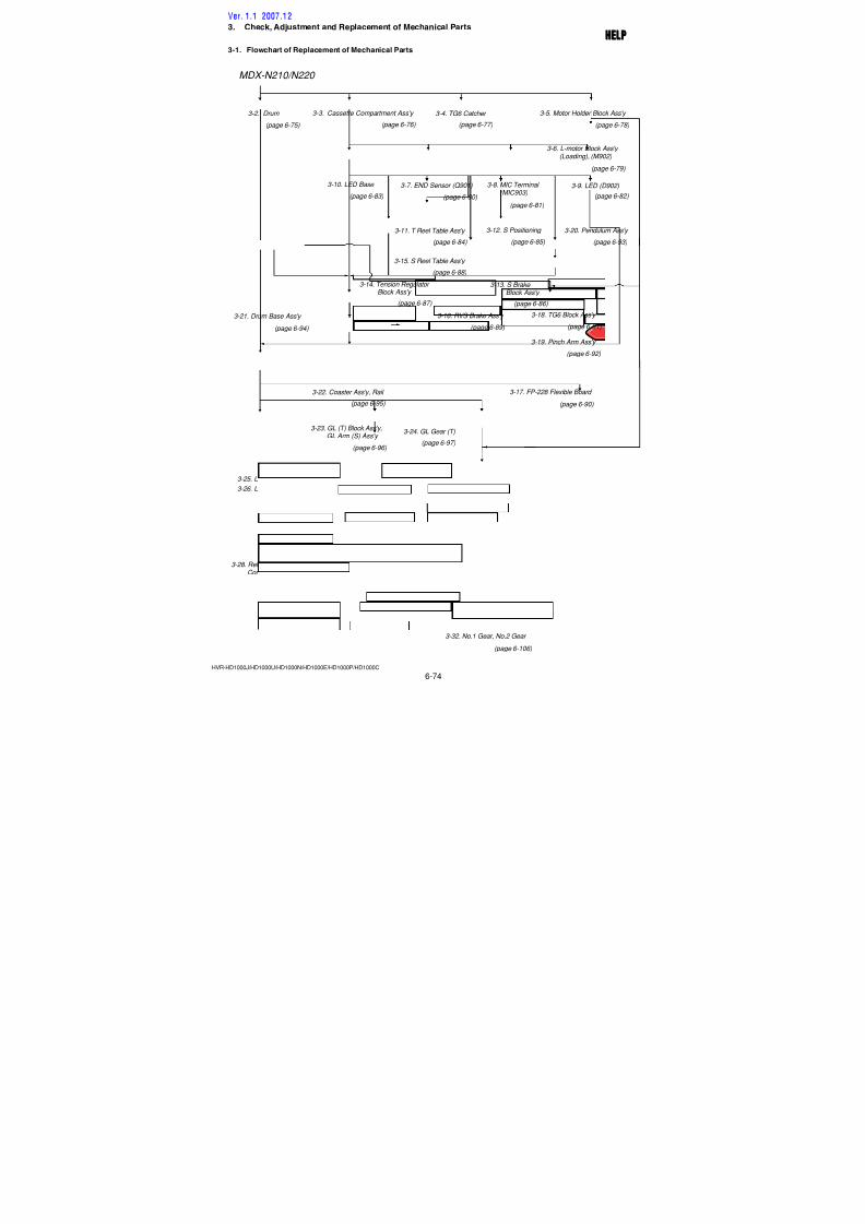
7/18/2019 SONY+HVR-HD1000 SERVICE MANUAL
http://slidepdf.com/reader/full/sonyhvr-hd1000-service-manual 206/4256-58HVR-HD1000J/HD1000U/HD1000N/HD1000E/HD1000P/HD1000C
27. HS White Defect Adjustment adaradarRadarW
Defect white defective pixels of CMOS image sensor. (HS mode)
Subject Not required
Measurement PointAdjusting remote commander
Measuring Instrument
Specified value Data of page: 6 address: D3 is “00”Note 1: Perform “MAX GAIN Adjustment” before this adjust-
ment.
Note 2: Check that the data of page: 0, address: 10 is “00”.
Switch setting
1) POWER ............................................. CAMERA-TAPE mode
Preparation for adjustment:
1) Before starting this adjustment, make sure that the lens ther-
mistor data of the set exceeds 37 degrees. If not, perform the
aging by the following method (aging temperature judge mode)
until the temperature exceeds 37 degrees.
Aging temperature judge mode:
Order Page Address Data Procedure
1Reverse and close the panel
of the set.
2 0 01 01
3 0 10 06
4B
7C 25 Press PAUSE (Write) button.(6B)
5
During the aging, the screen
will be as follows.(Fig. 6-1-18)
When the temperature isbelow 37 ºC, “grid” screen
appears. When the aging
continues and the tempera-
ture exceeds 37 ºC, “ color
bar” screen appears.
6
When the aging completed,
execute the subsequent steps
to exit the aging temperature judge mode.
7B
7C 00 Press PAUSE (Write) button.(6B)
8 0 10 00
9 0 01 00
Note 3: If the temperature does not rise despite the aging, coverthe set with a bubble cushioning material such as the Air
Cap and energize it.
Fig.6-1-18
Adjusting method:
Order Page Address Data Procedure
1 0 01 01
2 6 D0 88
3 6 01 21 Press PAUSE (Write) button.
4 6 02 Check the data changes to“01”.
5 6 01 00 Press PAUSE (Write) button.
6 6 02Check the data is ”00”.
(Note 4)
7 6 E0Check the data is “25” to
“50”. (Note 5)
8 6 07 Check the data is “04”.
9 0 10 06
102
BA 3F Press PAUSE (Write) button.(62)
112
BB 30 Press PAUSE (Write) button.(62)
12 0 10 00
13 6 0E 81
14 Wait for 1 second.
15 6 D0 44
16 6 01 21 Press PAUSE (Write) button.
17 6 02Check the data changes to
“01”.
Note 4: If not, select page: 6, address: 01, set data: 00, and press
PAUSE (Write) button.
Note 5: If the data is other than “25” to “50”, perform the aging.
Processing after Completing Adjustment:
Order Page Address Data Procedure
1 6 01 00 Press PAUSE (Write) button.
2 6 0E 00
3 Wait for 1 second.
4 0 10 06
52
BA 20 Press PAUSE (Write) button.(62)
62
BB 20 Press PAUSE (Write) button.(62)
7 0 10 00
8 0 01 00
Aging completed(Exceeding the settemperature)
During aging(Below the set temperature)
Ver. 1.2 2008.04
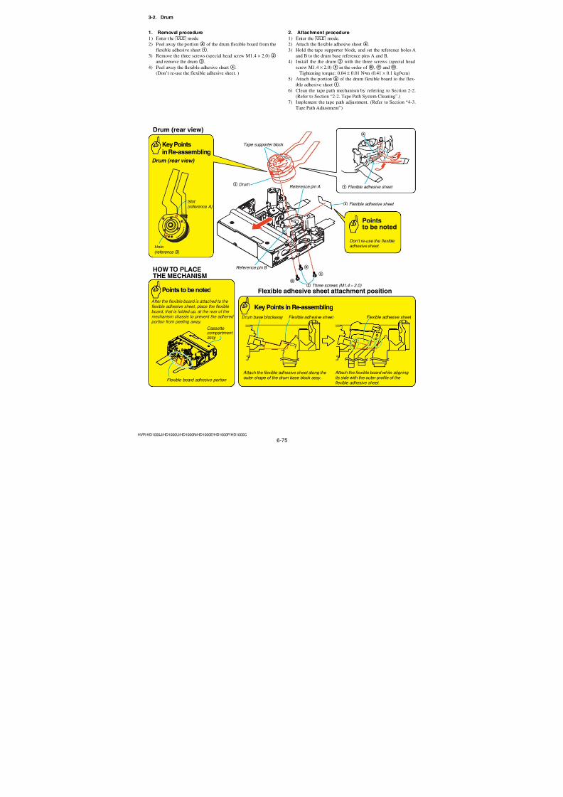
7/18/2019 SONY+HVR-HD1000 SERVICE MANUAL
http://slidepdf.com/reader/full/sonyhvr-hd1000-service-manual 207/4256-59HVR-HD1000J/HD1000U/HD1000N/HD1000E/HD1000P/HD1000C
28. White Defect Adjustment RadarW adarRadarW adarRadarW
Defect white defective pixels of CMOS image sensor.
Subject Not required
Measurement PointAdjusting remote commander
Measuring Instrument
Specified value Data of page: 6 address: D3 is “00”or “02” to “FF”.
Note 1: Perform “HS White Defect Adjustment” before this ad-
justment.
Note 2: Perform adjustments successively, starting from the “HS
White Defect Adjustment”.
Note 3: The lens thermistor data of the set must exceed 37 de-
grees.
If not, perform the aging in the aging temperature judgemode until the set exceeds 37 degrees.
Note 4: Check that the data of page: 0, address: 10 is “00”.
Switch setting
1) POWER ............................................. CAMERA-TAPE mode
Adjusting method:
Order Page Address Data Procedure
1 0 01 01
2 6 02Check the data is “00”.
(Note 5)
3 6 E0Check the data is “25” to
“50”. (Note 6)
4 6 07 Check the data is “04”.
5 6 D0 06
6 6 01 21 Press PAUSE (Write) button.
7 Wait for 10 seconds.
8 6 02Check the data changes to
“01”.
9 6 D3Check the data is “00” or“02” to “FF”.
Note 5: If not, select page: 6, address: 01, set data: 00, and press
PAUSE (Write) button.
Note 6: If the data is other than “25” to “50”, perform the aging.
Processing after Completing Adjustment:
Order Page Address Data Procedure
1 6 01 00 Press PAUSE (Write) button.2 0 01 00
29. White Defect Adjustment (FD white point)
adaradarRadarW
Defect white defective pixels (FD white point) of CMOS image
sensor.
Subject Not required
Note 1: Perform “White Defect Adjustment” before this adjust-ment.Note 2: Perform adjustments successively, starting from the “HS
White Defect Adjustment”.Note 3: The lens thermistor data of the set must exceed 37 de-
grees.
If not, perform the aging in the aging temperature judge
mode until the set exceeds 37 degrees.
Note 4: Check that the data of page: 0, address: 10 is “00”.
Switch setting
1) POWER ............................................. CAMERA-TAPE mode
Adjusting method:
Order Page Address Data Procedure
1 0 01 01
2 6 02Check the data is “00”.
(Note 5)
3 6 E0Check the data is “25” to
“50”. (Note 6)
4 6 07 Check the data is “04”.
5 6 D0 0C
6 6 01 21 Press PAUSE (Write) button.
7 6 02Check the data changes to“01”.
Note 5: If not, select page: 6, address: 01, set data: 00, and press
PAUSE (Write) button.
Note 6: If the data is other than “25” to “50”, perform the aging.
Processing after Completing Adjustment:
Order Page Address Data Procedure
1 6 01 00 Press PAUSE (Write) button.
2 0 01 00
Ver. 1.2 2008.04
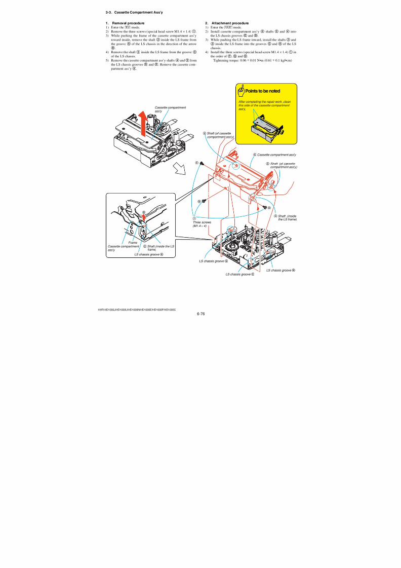
7/18/2019 SONY+HVR-HD1000 SERVICE MANUAL
http://slidepdf.com/reader/full/sonyhvr-hd1000-service-manual 208/4256-60HVR-HD1000J/HD1000U/HD1000N/HD1000E/HD1000P/HD1000C
30. White Defect Check RadarW adarRadarW adarRadarW
Subject Not required
Measurement PointAdjusting remote commander
Measuring Instrument
Specified value 1 Data of page: 6 address: D1 is “00”
Specified value 2 Data of page: 6, address: D2 is “00”to “08”
Note 1: Perform “White Defect Adjustment” before this adjust-
ment.Note 2: Perform adjustments successively, starting from the “HS
White Defect Adjustment”.Note 3: The lens thermistor data of the set must exceed 37 de-
grees.
If not, perform the aging in the aging temperature judge
mode until the set exceeds 37 degrees.
Note 4: Check that the data of page: 0, address: 10 is “00”.
Switch setting
1) POWER ............................................. CAMERA-TAPE mode
Adjusting method:
Order Page Address Data Procedure
1 0 01 01
2 6 02Check the data is “00”.
(Note 5)
3 6 E0Check the data is “25” to“50”. (Note 6)
4 6 07 Check the data is “04”.
5 6 D0 04
6 6 01 21 Press PAUSE (Write) button.
7 6 02 Check the data changes to“01”.
8 6 D1 Check the data is “00”.
9 6 D2 Check the data is “00” to
“08”.
Note 5: If not, select page: 6, address: 01, set data: 00, and pressPAUSE (Write) button.
Note 6: If the data is other than “25” to “50”, perform the aging.
Processing after Completing Adjustment:
Order Page Address Data Procedure
1 6 01 00 Press PAUSE (Write) button.2 0 01 00
31. Black Defect Adjustment adaradarRadarW
Defect black defective pixels of CMOS image sensor.
Subject Clear chart (All white) (Note 1)
Note 1: Perform “White Defect Adjustment” before this adjust-
ment.Note 2: Perform adjustments successively, starting from the “HS
White Defect Adjustment”.Note 3: The lens thermistor data of the set must exceed 37 de-
grees.
If not, perform the aging in the aging temperature judge
mode until the set exceeds 37 degrees.Note 4: Shoot the clear chart with the zoom TELE end.Note 5: Check that the data of page: 0, address: 10 is “00”.
Switch setting
1) POWER ............................................. CAMERA-TAPE mode
Adjusting method:
Order Page Address Data Procedure
1 Turn off the power and turn
on again.
2 0 01 01
3 6 02Check the data is “00”.
(Note 6)
4 6 E0Check the data is “25” to
“50”. (Note 7)
5 6 07 Check the data is “04”
6 6 2C 01
7 6 90 00
8 6 91 04
9 6 92 00
10 6 93 10
11 6 01 79 Press PAUSE (Write) button.
12 Wait for 1.5 seconds.
13 Check that the entire screen
is white.
14 6 D0 01
15 6 01 21 Press PAUSE (Write) button.
16 6 02 Check the data changes to
“01”.
Note 6: If not, select page: 6, address: 01, set data: 00, and press
PAUSE (Write) button.Note 7: If the data is other than “25” to “50”, perform the aging.
Processing after Completing Adjustment:
Order Page Address Data Procedure
1 6 01 00 Press PAUSE (Write) button.
2 6 90 00
3 6 91 00
4 6 92 00
5 6 93 00
6 6 01 79 Press PAUSE (Write) button.
7 Wait for 1.5 seconds.
8 6 01 00 Press PAUSE (Write) button.
9 6 2C 00
10 0 01 00
Ver. 1.2 2008.04
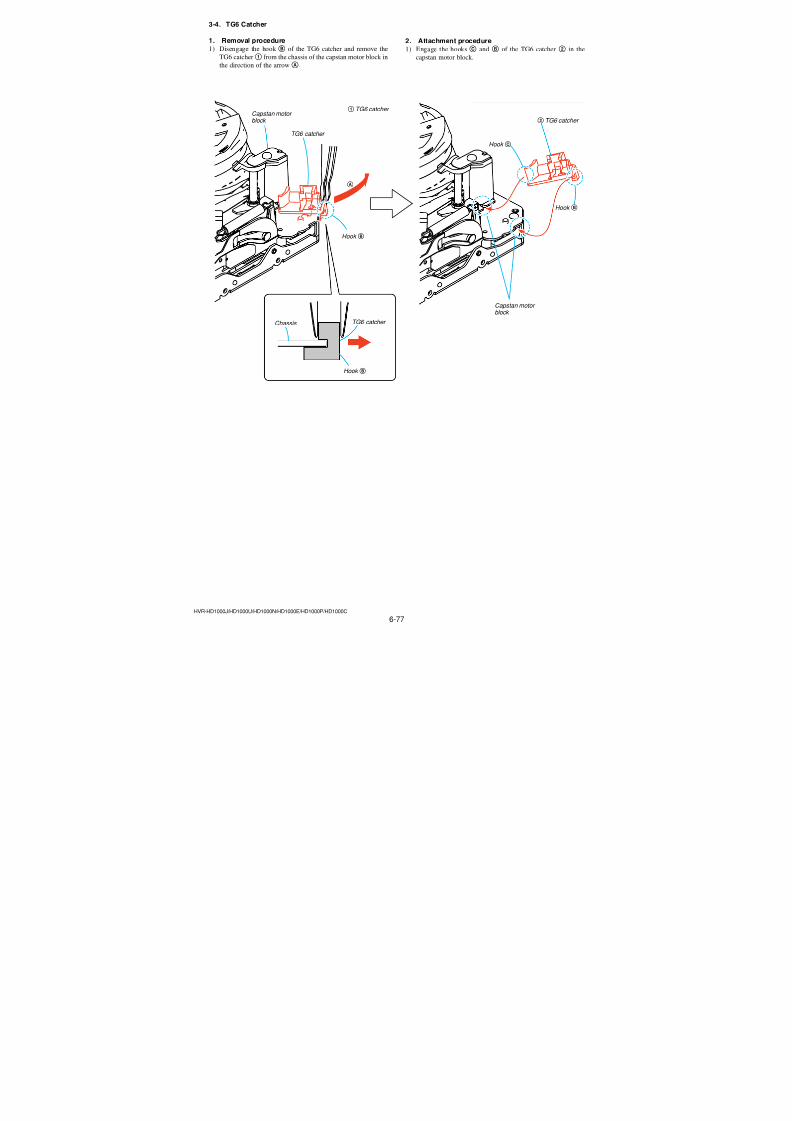
7/18/2019 SONY+HVR-HD1000 SERVICE MANUAL
http://slidepdf.com/reader/full/sonyhvr-hd1000-service-manual 209/4256-61HVR-HD1000J/HD1000U/HD1000N/HD1000E/HD1000P/HD1000C
32. Angular Velocity Sensor Sensitivity AdjustmentAdjust the gain to eliminate the output dispersion Angular veloc-ity sensor.
Perform this adjustment when the lens block is replaced, CM-077
board is replaced, or Hall sensor is adjusted.
Do not perform this adjustment and check the Steady Shot opera-
tion only, if the microcomputer or board other than this lens block
failed.32-1. Preparation when the angular velocity sensor or
the CM-077 board is replacedNote down the sensitivity displayed on the angular velocity sensor
of the repair parts. At this time, note down also to which board it was
attached to.
Be sure to check because if attached incorrectly, the screen will vi-
brate up and down or left and right during the steady shot operations.
Precautions on the Parts ReplacementThe PITCH sensor and the YAW sensor are different parts.
Precautions on Angular Velocity SensorThe sensor incorporates a precision oscillator. Handle it with care as
if it dropped, the balance of oscillator will be disrupted and opera-
tions will not be performed properly.
Adjustment Page 7F
Adjustment Address 12, 13
Note 1:The sensor sensitivity of SE7201 and SE7202 of the CM-
077 board is written only repair parts.
Preparation:
1) Read the PITCH sensor (CM-077 board SE7202) sensitivity
written on repair parts, and named this as P12.
2) Read the YAW sensor (CM-077 board SE7201) sensitivity writ-
ten on repair parts, and named this as Y12.
Fig. 6-1-19 (1)
Note 2: Only the value of decimal places has been written to the
angular velocity sensor.
How to read the sensitivity data of angular velocity sen-sorWith the pins 1 and 2 of angular velocity sensor placed in the
lower position, read the data value.
Fig. 6-1-19 (2)
32-2. Preparation when the lens is replacedNote down the PITCH/YAW data on the replacement lens for repair.
Adjustment Page 7FAdjustment Address 12, 13
Note: The PITCH/YAW data of lens is written only repair parts.
Preparation:
1) Read the PITCH data written on repair parts, and named this
as L1.2) Read the YAW data written on repair parts, and named this as
L2.
Fig. 6-1-20
YAW data t L2
PITCH/YAW Data
PITCH datat L1
X.XX / X.XX
S E 7 2 0 2
S E 7 2 0 1
1
2
4
3
1 2
4 3
CM-077 BOARD (SIDE A)
P P Y Y
YAW sensor sensitivity t Y12
PITCH sensor sensitivityt P12
For the sensor sensitivity value 60
6 0
Hand Writing
1 2
4 3
Description example :
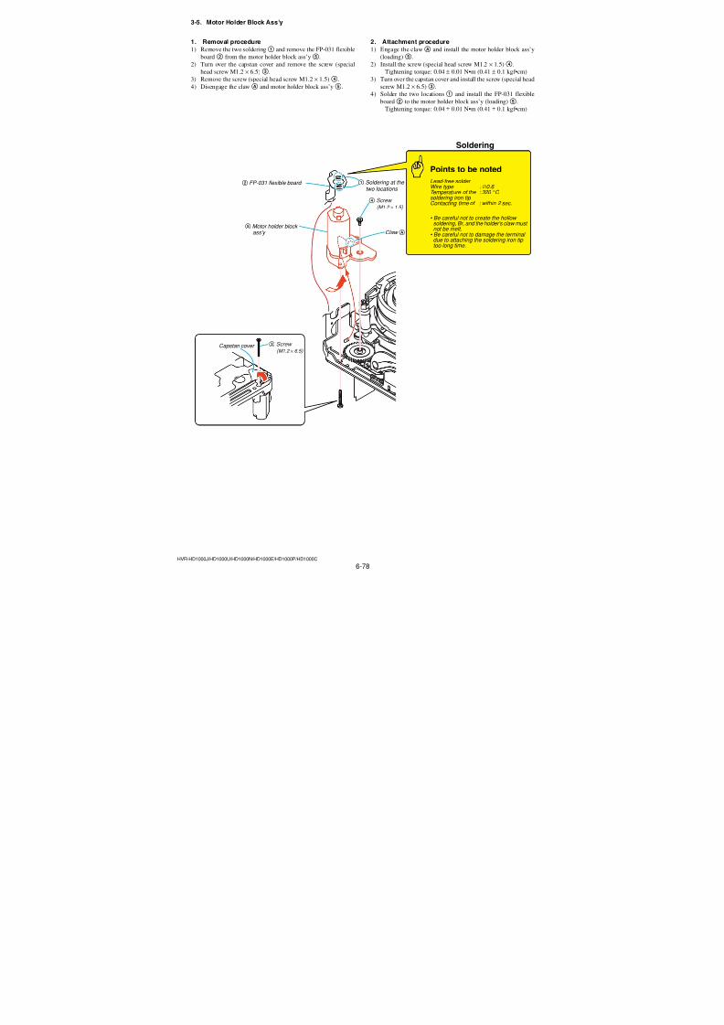
7/18/2019 SONY+HVR-HD1000 SERVICE MANUAL
http://slidepdf.com/reader/full/sonyhvr-hd1000-service-manual 210/4256-62HVR-HD1000J/HD1000U/HD1000N/HD1000E/HD1000P/HD1000C
32-3. Angular Velocity Sensor Sensitivity AdjustmentAdjusting method:
Order Page Address Data Procedure
1 0 01 01
2
Using the following formula
calculate:
Gain adjustment value of angular velocity sensor in
pitch direction D12’ (decimal
number)
Gain adjustment value of
angular velocity sensor in
yaw direction D13’ (decimal
number)(Note 1)
D12’= 95 × P12 × L1
D13’= 95 × Y12 × L2
3
Convert D12’ and D13’ into
hexadecimal numbers and
assume them as D12 and D13
respectively. (Note 2, 3)
4 0 10 07
5F
12 D12 Press PAUSE (Write) button.(7F)
6F
13 D13 Press PAUSE (Write) button.(7F)
7 0 10 00
8 0 01 00
Note 1: If the gain data of angular velocity sensor is not avail-
able, perform calculation with P12=Y12=0.6.
Also, if the lens data is not available, perform calcula-
tion with L1=L2=1.Note 2: Round off the decimal places of the calculation results.
Note 3: Refer to table 6-4-1. “Hexadecimal-decimal conversion
table”.
Processing after Completing Adjustment:
Order Page Address Data Procedure
1Turn off the power and turn
on again.
2 0 01 01
3 0 10 07
4
F
12 D12
Check that the data D12 is
(7F) reflected correctly.
5F
13 D13Check that the data D13 is
(7F) reflected correctly.
6 0 10 00
7
Check that the steady shot
operates normally when it is
turned on.
8 0 01 00
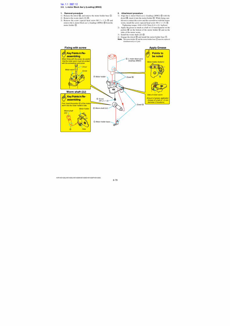
7/18/2019 SONY+HVR-HD1000 SERVICE MANUAL
http://slidepdf.com/reader/full/sonyhvr-hd1000-service-manual 211/4256-63HVR-HD1000J/HD1000U/HD1000N/HD1000E/HD1000P/HD1000C
1-4. ELECTRONIC VIEWFINDER SYSTEMADJUSTMENTS
Before perform the viewfinder system adjustments, check the data
of page: 0, address: 10 is “00”.If not, select page: 0, address: 10, and set the data “00”.
Note 1: Taken an extreme care not to destroy the liquid crystal
display module by static electricity when replacing it.
Note 2: Perform the following data setting before the viewfinder
system adjustments.
1) Select page: 3, address: C4, and set data: 67.2) Select page: 3, address: C5, and set data: 01.
Reset the data after completing adjustment.
1) Select page: 3, address: C4, and set data: 00.
2) Select page: 3, address: C5, and set data: 00.
1. EVF Automatic Adjustment (VC-500 board)
RadarW adarRadarW adarRadarW
This adjustment does the following items automatically.
VCO Adjustment
Contrast Adjustment
Mode VTR stop (PLAY/EDIT mode)
Signal No signal
Adjustment Page C
Adjustment Address 34, 35 (VCO Adjustment)
3C, 77 (Contrast Adjustment)
Note 1: Check that the data of page: 0, address: 10 is “00”.
Note 2: If the data change to “01”, adjustment has error. Con-
tents of error is written into page: 3, address: C6. See the
following table.
Data of page: 3, address: C6 Contents of error
5E VCO adjustment error
61 Contrast adjustment error
Note 3: Refer to Table 6-4-1. “Hexadecimal-decimal conversion
table”.
Adjusting method:
Order Page Address Data Procedure
1 0 01 01
2 3 03 FF
3 3 71 01 Press PAUSE (Write) button.
4 C 66 00 Press PAUSE (Write) button.
5 3 01 5A Press PAUSE (Write) button.
(Note 4)
6 3 02 Check the data changes to “00”.
7 3 03 Check the data is “00”. (Note 2)
8 C 66 41 Press PAUSE (Write) button.
9 3 70 10 Press PAUSE (Write) button.
10 3 70 Check the data changes to “11”.
11 0 01 00
Note 4: The adjustment data will be automatically input to page:
C, address: 34 and 3C.
2. White Balance Adjustment (VC-500 board)Correct the white balance.If deviated, the EVF screen color cannot be reproduced.
Mode VTR stop (PLAY/EDIT mode)
Signal No signal
Measurement PointCheck on EVF screenMeasuring Instrument
Adjustment Page C
Adjustment Address 3A, 3B
Specified Value EVF screen must not be colored
Note 1: Check that the data of page: 0, address: 10 is “00”.Note 2: Check the white balance only when replacing the fol-
lowing parts. If necessary, adjust them.
1. LCD panel
2. Light induction plate
3. IC3701
Adjusting method:
Order Page Address Data Procedure
1 0 01 01
2 3 71 01 Press PAUSE (Write) button.
3 C 3A 93 Press PAUSE (Write) button.
4 C 3B 7F Press PAUSE (Write) button.
5Check that the EVF screen is
not colored. If not colored,proceed to step 6.
6 C3A Change the data so that the
EVF screen is not colored.3B (Note 3)
7 3 70 10 Press PAUSE (Write) button.
8 3 70 Check the data changes to “11”.
9 0 01 00
Note 3: To write in the non-volatile memory (EEPROM), press
the PAUSE (Write) button each time to set the data.
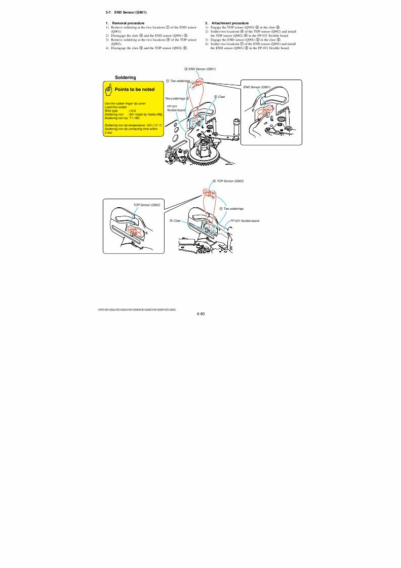
7/18/2019 SONY+HVR-HD1000 SERVICE MANUAL
http://slidepdf.com/reader/full/sonyhvr-hd1000-service-manual 212/4256-64HVR-HD1000J/HD1000U/HD1000N/HD1000E/HD1000P/HD1000C
1-5. LCD SYSTEM ADJUSTMENTSBefore perform the LCD system adjustments, check that the data
of page: 0, address: 10 is “00”.If not, select page: 0, address: 10, and set the data “00”.
Note 1: Taken an extreme care not to destroy the liquid crystal
display module by static electricity when replacing it.
Note 2: Set the “LCD BRIGHT”, “LCD COLOR” to the centerwith the menu settings of the touch panel.
Note 3: Open the LCD panel during the LCD system adjustment.
1. LCD Automatic Adjustment (PD-342 board)
RadarW adarRadarW adarRadarW
This adjustment does the following items automatically.
VCO Adjustment
Contrast Adjustment
Mode VTR stop (PLAY/EDIT mode)
Signal No signal
Adjustment Page C
Adjustment Address 45, 46 (VCO Adjustment)
4D, 76 (Contrast Adjustment)
Note 1: Check that the data of page: 0, address: 10 is “00”.Note 2: If the data change to “01”, adjustment has error. Con-
tents of error is written into page: 3, address: C6. See the
following table.
Data of page: 3, address: C6 Contents of error
58 VCO adjustment error
60 Contrast adjustment error
Note 3: Refer to Table 6-4-1. “Hexadecimal-decimal conversion
table”.
Adjusting method:
Order Page Address Data Procedure
1 0 01 01
2 3 03 FF
3 3 71 01 Press PAUSE (Write) button.
4 C 65 00 Press PAUSE (Write) button.
5 3 01 5A Press PAUSE (Write) button.
(Note 4)
6 3 02 Check the data changes to “00”.
7 3 03 Check the data is “00”. (Note 2)
8 C 65 41 Press PAUSE (Write) button.
9 3 70 10 Press PAUSE (Write) button.
10 3 70 Check the data changes to “11”.
11 0 01 00
Note 4: The adjustment data will be automatically input to page:
C, address: 45 and 4D.
2. V-COM Adjustment (PD-342 board)Set the DC bias of the common electrode drive signal of LCD to
the specified value.If deviated, the LCD display will be move, producing flicker and
conspicuous vertical lines.
Mode VTR stop (PLAY/EDIT mode)
Signal No signal
Measurement PointCheck on LCD screen
Measuring Instrument
Adjustment Page C
Adjustment Address 47
Specified Value The brightness difference betweenthe section-A and section-B is
minimum
Note 1: Perform “LCD Automatic Adjustment” before this ad-
justment.Note 2: Check that the data of page: 0, address: 10 is “00”.
Switch setting
LCD BACKLIGHT .................................................................. ON
Adjusting method:
Order Page Address Data Procedure
1 0 01 01
2 3 71 01 Press PAUSE (Write) button.
3 C 56 0D Press PAUSE (Write) button.
4 C 47
Change the data so that
brightness of the section A
and section B is equal.
5 C 47 Press PAUSE (Write) button.6 C 56 05 Press PAUSE (Write) button.
7 3 70 10 Press PAUSE (Write) button.
8 3 70 Check the data changes to “11”.
9 0 01 00
Fig. 6-1-21
A
A
A
A
B
B
B
B
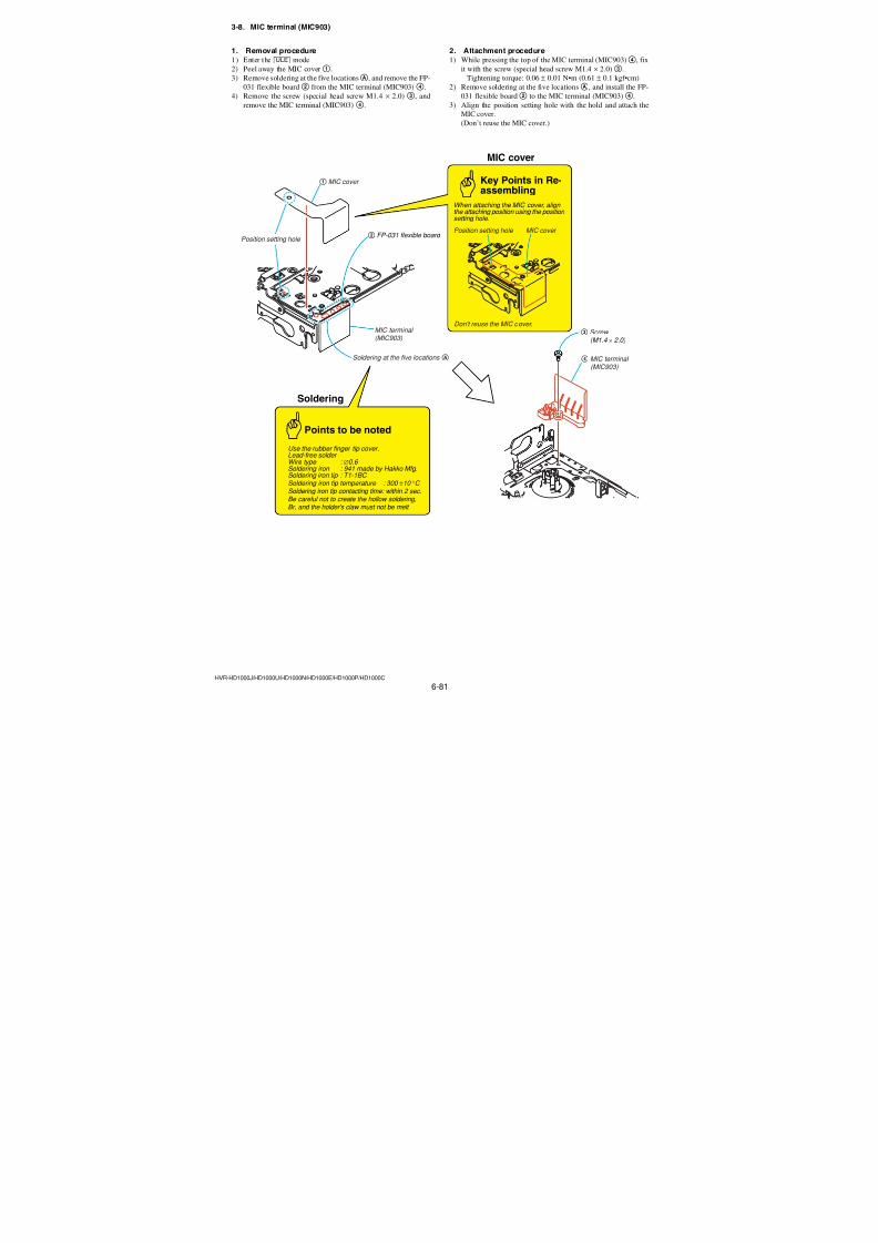
7/18/2019 SONY+HVR-HD1000 SERVICE MANUAL
http://slidepdf.com/reader/full/sonyhvr-hd1000-service-manual 213/4256-65HVR-HD1000J/HD1000U/HD1000N/HD1000E/HD1000P/HD1000C
4. Reflective Mode White Balance Adjustment RadarW adarRadarW adarRadarW
(PD-342 board)Correct the white balance at reflective mode.
If deviated, the LCD screen color cannot be reproduced.
Mode VTR stop (PLAY/EDIT mode)
Signal No signal
Adjustment Page C
Adjustment Address 70, 71
Note 1: Check that the data of page: 0, address: 10 is “00”.
Adjusting method:
Order Page Address Data Procedure
1 0 01 01
2 8 1D 60 Press PAUSE (Write) button.
3 3 C4 59
4 3 C5 02
5 3 0C 20 Press PAUSE (Write) button.
6 3 22 0F Press PAUSE (Write) button.
7 3 71 01 Press PAUSE (Write) button.
8 3 03 FF
9 3 01 66 Press PAUSE (Write) button.
(Note 2)
10 3 02 Check the data changes to“00”.
11 3 03 Check the data is “00”. (Note 4)
12 3 03 FF
13 3 01 67 Press PAUSE (Write) button.
(Note 3)
14 3 02 Check the data changes to“00”.
15 3 03 Check the data is “00”. (Note 4)
16 3 C4 00
17 3 C5 00
18 3 0C 00 Press PAUSE (Write) button.
19 3 22 00 Press PAUSE (Write) button.
20 8 1D 00 Press PAUSE (Write) button.
21 3 70 10 Press PAUSE (Write) button.
22 3 70 Check the data changes to
“11”.
23 0 01 00
Note 2: The adjustment data will be automatically input to page:C, address: 70.
Note 3: The adjustment data will be automatically input to page:
C, address: 71.
Note 4: If the data is “01”, adjustment has error.
3. Transmissive Mode White Balance Adjustment(PD- 342 board)
Correct the white balance at transmissive mode.
If deviated, the LCD screen color cannot be reproduced.
Mode VTR stop (PLAY/EDIT mode)
Signal No signal
Measurement PointCheck on LCD screen
Measuring Instrument
Adjustment Page C
Adjustment Address 4B, 4C
Specified Value LCD screen must not be colored
Note 1: Check that the data of page: 0, address: 10 is “00”.
Note 2: Check the white balance only when replacing the fol-
lowing parts. If necessary, adjust them.
1. LCD block
2. Light induction plate
3. IC6201
Adjusting method:
Order Page Address Data Procedure
1 0 01 01
2 3 71 01 Press PAUSE (Write) button.
3 C 4B 8A Press PAUSE (Write) button.
4 C 4C 64 Press PAUSE (Write) button.
5
Check that the LCD screen isnot colored. If not colored,
proceed to step 6.
6 C4B
Change the data so that the
LCD screen is not colored.
(Note 3)
7 3 70 10 Press PAUSE (Write) button.
8 3 70 Check the data changes to “11”.
9 0 01 00
Note 3: To write in the non-volatile memory (EEPROM), press
the PAUSE (Write) button each time to set the data.
4C
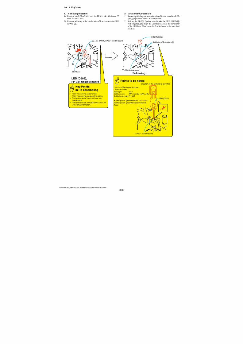
7/18/2019 SONY+HVR-HD1000 SERVICE MANUAL
http://slidepdf.com/reader/full/sonyhvr-hd1000-service-manual 214/4256-66HVR-HD1000J/HD1000U/HD1000N/HD1000E/HD1000P/HD1000C
5. Sample Hold Phase Adjustment (PD-342 board)Set the sampling hold timing of the LCD panel to optimum tim-ing.
Mode VTR stop (PLAY/EDIT mode)
Signal No signal
Measurement PointCheck on LCD screenMeasuring Instrument
Adjustment Page C
Adjustment Address 54
Specified Value The LCD screen is brightest
Note 1: Perform “LCD Automatic Adjustment” and “V-COMAdjustment” before this adjustment.
Note 2: Check that the data of page: 0, address: 10 is “00”.
Switch setting
LCD BACKLIGHT .................................................................. ON
Adjusting method:
Order Page Address Data Procedure
1 0 01 01
2 3 71 01 Press PAUSE (Write) button.
3 3 0C 20 Press PAUSE (Write) button.
4 3 22 0F Press PAUSE (Write) button.
5 C 55 01 Press PAUSE (Write) button.
6 C 54
Set the following data, one
by one, and investigate which
data makes the LCD screen
the brightest.1F, 3F, 5F, 7F, 9F, BF
7 C 54
Set the data which made the
LCD screen the brightest.This data named Dadj.
8 C 54 Dadj Press PAUSE (Write) button.
9 C 55 CC Press PAUSE (Write) button.
10 3 0C 00 Press PAUSE (Write) button.
11 3 22 00 Press PAUSE (Write) button.
12 3 70 10 Press PAUSE (Write) button.
13 3 70 Check the data changes to
“11”.
14 0 01 00
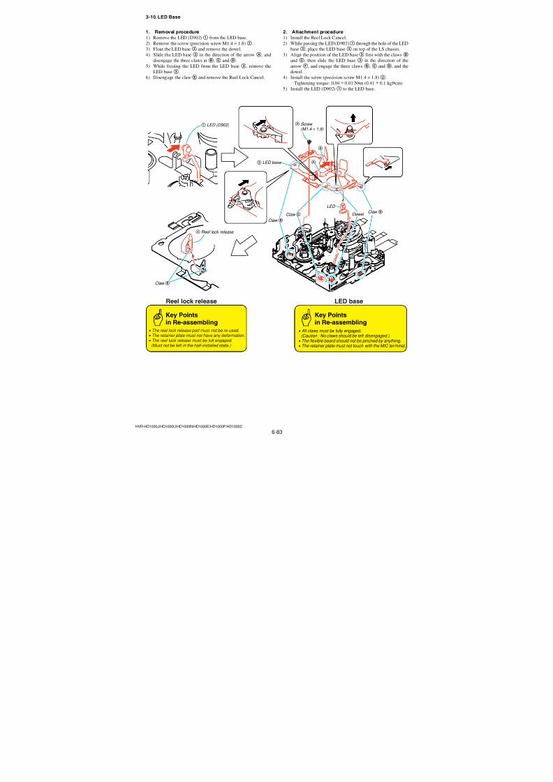
7/18/2019 SONY+HVR-HD1000 SERVICE MANUAL
http://slidepdf.com/reader/full/sonyhvr-hd1000-service-manual 215/4256-67HVR-HD1000J/HD1000U/HD1000N/HD1000E/HD1000P/HD1000C
6. Touch Panel AdjustmentAdjust the calibration of touch panel.
Mode VTR stop (PLAY/EDIT mode)
Signal No signal
Adjustment Page A
Adjustment Address 90 to 93Note 1: This adjustment should be carried out upon completetion
of “LCD Automatic Adjustment”.
Note 2: Check that the data of page: 0, address: 10 is “00”.
Note 3: Check that a Memory Stick Duo is not insteted.
Note 4: Check that the LCD panel is not reverse mode.Note 5: Adjustment must be performed while observing the LCD
screen from the front.
Preparation:
Order Page Address Data Procedure
1 0 01 01
2 7 01 383 7 02 FF
4 7 04 02
5 7 00 01 Press PAUSE (Write) button.
6 7 02 Check the data changes to
“01”.
7 7 01 C9
8 7 02 FF
9 7 00 01 Press PAUSE (Write) button.
10 7 02 Check the data changes to
“01”.
11 Check that the touch paneladjustment screen is
displayed.
12 Perform “Adjusting method”.
Adjusting method:
1) Using a ball-point pen etc., push the center of “×” indicated in
the part A.
2) Using a ball-point pen etc., push the center of “×” indicated in
the part B.
3) Using a ball-point pen etc., push the center of “×” indicated in
the part C.
Fig. 6-1-22
Processing after Completing Adjustment:
Order Page Address Data Procedure
1 7 01 38
2 7 02 FF
3 7 04 01
4 7 00 01 Press PAUSE (Write) button.
5 7 02Check the data changes to
“01”.
6 0 01 00
AC
B
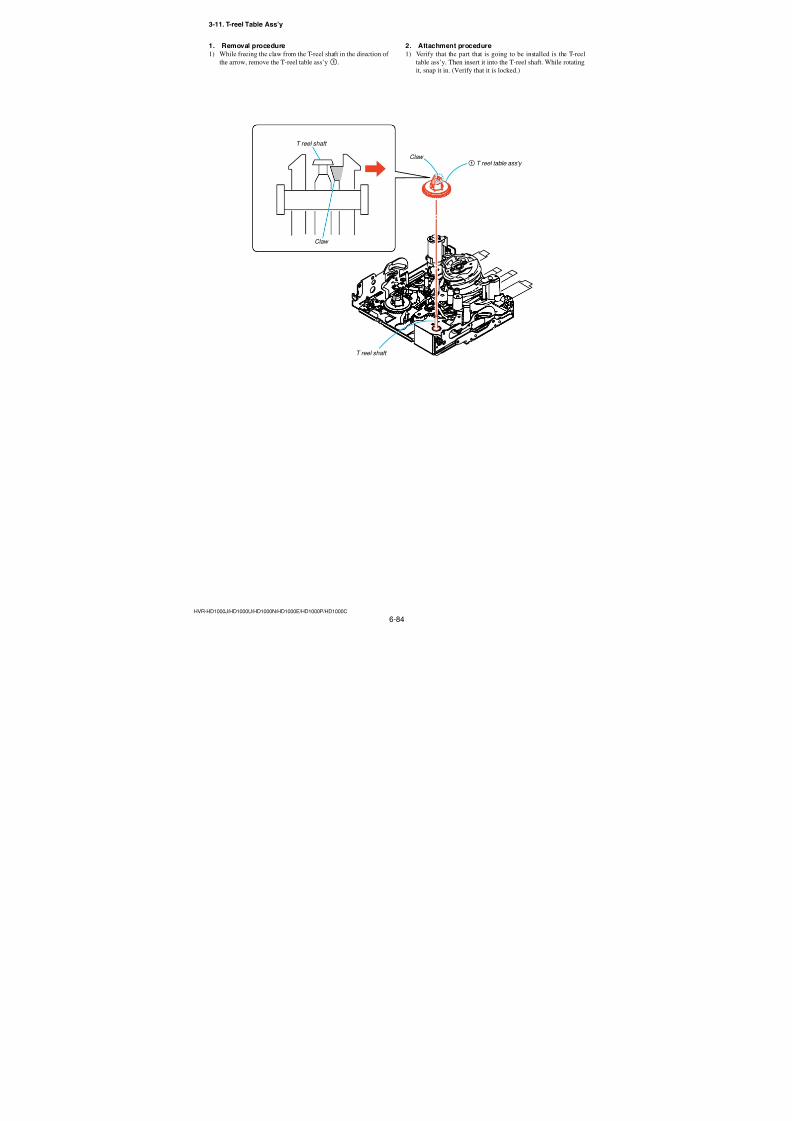
7/18/2019 SONY+HVR-HD1000 SERVICE MANUAL
http://slidepdf.com/reader/full/sonyhvr-hd1000-service-manual 216/4256-68HVR-HD1000J/HD1000U/HD1000N/HD1000E/HD1000P/HD1000C
• Refer to the “DISASSEMBLY” section of the SERVICE MANUAL of the respective models for details of removing cabinets and
printed wiring boards.
• When making any adjustment to a mechanism or replacing mechanical parts, be sure to use the Mode Selector II and select theappropriate status of the mechanical deck such that the mechanical status is suitable for the desired work. Refer to section “2-4. Mode
Selector II” for details on how to enter the mode shown in a rectangle [] mode in subsequent paragraphs of this manual.
6-2. MECHANISM SECTION ADJUSTMENTS
1. Preparations for Check, Adjustment and Replacement of Mechanism Block
• Be sure to perform the following maintenance and inspection sothat the machine delivers its full performance and functions, and
to protect the machine and tape. Also, perform the following
maintenance items after completing the repair work, regardless
of the number of hours the machine has been operated by the
user.
2-1. Rotary Drum Cleaning
1) Press a wiping cloth (Ref. No. J-20) moistened with head clean-
ing liquid (Ref. No. J-19) lightly against the rotary drum. Ro-
tate the upper drum with a super-fine applicator slowly in the
counter-clockwise direction to clean the rotary drum.
Caution: Never rotate the rotary drum by turning on the main power of the motor or rotate it in the clockwise direction. Never move the
cloth vertically against the head tip, as this will surely damage
the video head; the video head must not be cleaned by any other
different methods.
2. Periodic Inspection and Maintenance
Fig. 6-2-1
Drum
Pinch roller
TG1
TG6
TG2 TG5 TG4
Capstan shaft cleaning
Oil seal
TG3
2-2. Tape Path System Cleaning(Refer to Fig. 6-2-1.)
1) Set the EJECT state. Clean the tape running path (TG-1, -2, -3,-4, -5 and -6 pinch roller and capstan shaft) and lower drum with a
super-fine applicator (Ref. J-21) moistened with head cleaning liq-
uid.
Note 1: NBe careful not to allow oil or grease of the various link
mechanisms to get on the super-fine applicator (Ref. J-21).Note 2: Once the super-fine applicator has been moistened with alcohol,
do not use it to clean other mechanical parts such as the tape
guide. However, the pinch roller is cleaned with alcohol.Note 3: When cleaning the capstan shaft, be carefull not to move the oil
seal. If the oil seal is moved, oil will leak.
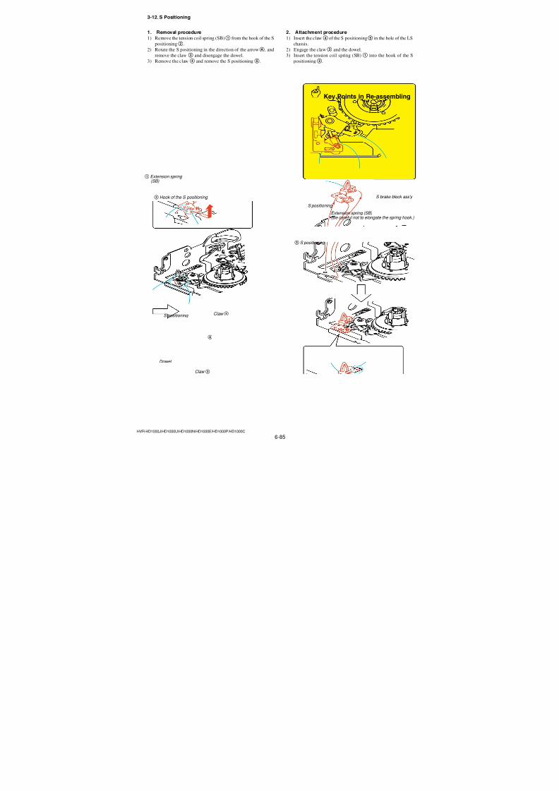
7/18/2019 SONY+HVR-HD1000 SERVICE MANUAL
http://slidepdf.com/reader/full/sonyhvr-hd1000-service-manual 217/4256-69HVR-HD1000J/HD1000U/HD1000N/HD1000E/HD1000P/HD1000C
Maintenance and inspection item
Tape running surface cleaning
Rotary drum cleaning and
degaussingCapstan bearing
Loading motor
Abnormal sound
Back-tension measurement
Brake system
FWD/RVS torque measurement
D r i v e
m e c
h a n
i s m
P e r f o r m a n c e
c h e c
k
500
a
a
—
—
—
—
—
1000
a
a
1500
a
a
—
—
—
—
—
2000
a
a
2500
a
a
—
—
—
—
—
3000
a
a
3500
a
a
—
—
—
—
—
4000
a
a
4500
a
a
—
—
—
—
—
5000
a
a
Remarks
Be careful not to attach oil
Be careful not to attach oil
Operating hours (H)
a: Cleaning, : Check
2-3. Periodic Inspection List
Note 1: When the machine is overhauled, replace the parts referring to the
above list.
Note 2: Grease• Be sure to use the specified grease only. (If grease of different
viscosity is used, it can cause various troubles.)
• The grease must not contain any dust or other matter. (otherwise
it can cause various trouble.)
• Observe the noted amount of grease. (otherwise the oozed greasecan cause troubles.)
• Grease (SUNCALL FG-87HSR) : Part cord. 7-640-006-08
Ver. 1.1 2007.12
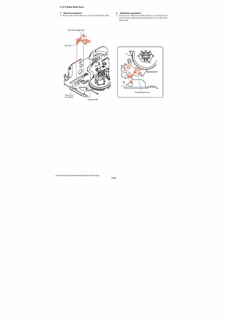
7/18/2019 SONY+HVR-HD1000 SERVICE MANUAL
http://slidepdf.com/reader/full/sonyhvr-hd1000-service-manual 218/4256-70HVR-HD1000J/HD1000U/HD1000N/HD1000E/HD1000P/HD1000C
2-4. Mode Selector II Operating Procedure
2-4-1. IntroductionThe Mode Selector II is a mechanism drive tool that assists main-tenance work of the various mechanism decks. It has the follow-
ing functions.
1. Manual TestIn this mode, the motor of the mechanism deck is powered only
during the period while the switch is turned on manually. Using
the Manual Test, the operator can freely control the motor of themechanism deck.
2. Step TestIn this mode, the motor of the mechanism deck is kept turned on
until the mechanical status is changed from the present mechani-
cal status that is obtained from the sensor information. The Step
Test is used to confirm a series of movements of the mechanismdeck.
3. Auto TestThe Mode Selector II stores the status transition table in its memory
as data indicating the respective modes of the mechanism deck.
The status transition table can be used to confirm whether a mecha-
nism deck is operating normally or has abnormality from a seriesof movements of a mechanism deck. If an abnormal status transi-
tion is detected during operation, the “NG” indication appears and
the mechanism stops moving.
Mode Selector II (J-6082-282-B) connection diagram
Fig. 6-2-2
Fig. 6-2-3
Alligator clip
(not used in N mechanism)
Mode Selector II
Battery such as NP-55, NP-77(power supply)
Connector (white) 6-pin
Relay board
Mode Selector IIconversion board (N)(Ref. No. J-29)
Connector (black) 6-pin(not used in N mechanism)
N mechanism
Mode Selector II(Ref. No. J-28)
Selector button
LCD display screen
External battery is
connected here asa power supply
Relay board(already connected)
Alligator clip
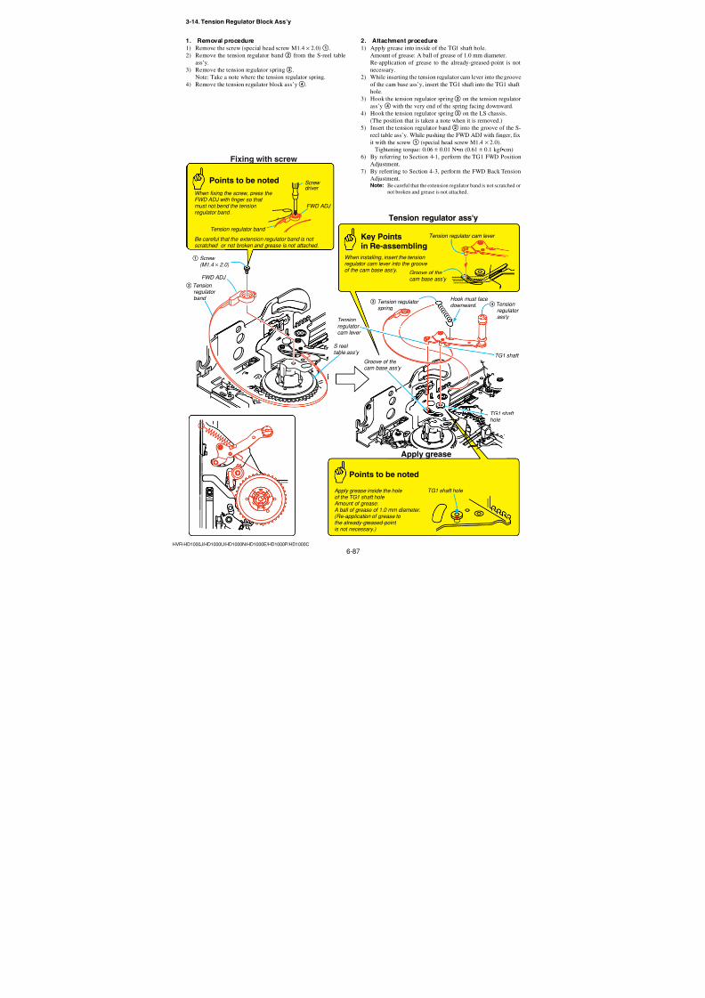
7/18/2019 SONY+HVR-HD1000 SERVICE MANUAL
http://slidepdf.com/reader/full/sonyhvr-hd1000-service-manual 219/4256-71HVR-HD1000J/HD1000U/HD1000N/HD1000E/HD1000P/HD1000C
2-4-2. Operation
1. Operation Flow Chart
Note: Be sure to use the Mode Selector II ROM (J-6082-314-G) (J-30).
(Refer to “1-2. List of service tools.”)
2. Mode Selector II Power OnTurn on the main power of the Mode Selector II as follows.
Press the SEL button.
3. Mode Selector II Power Off
Turn off the main power of the Mode Selector II as follows.Press the RVS and FF buttons at the same time for 2 seconds or
longer while the power is on.
SEL
SEL
SEL
STEP TEST MANUAL TEST AUTO TEST
POWER ON
MECHA SELECT
MODE SELECT
From any status
Press RVS and FF for
2 sec. simultaneously
Main power isturned off
RVS, FF
RVS, FF
RVS, FF SELRVS FF SELRVS FF SEL
RVS FF SEL
RVS FF SEL
Ver. 1.1 2007.12
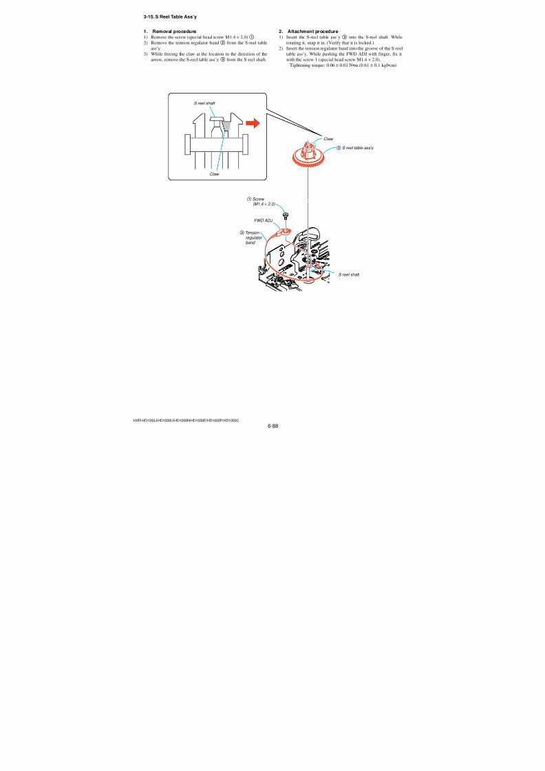
7/18/2019 SONY+HVR-HD1000 SERVICE MANUAL
http://slidepdf.com/reader/full/sonyhvr-hd1000-service-manual 220/4256-72HVR-HD1000J/HD1000U/HD1000N/HD1000E/HD1000P/HD1000C
4. Mecha SelectWhen the main power is turned on, the MECHA SELECT displayappears on the LCD screen. Select the desired mechanism name
using the RVS and FF buttons. Selection is complete when the
SEL button is pressed. (Fig. A shows the N mechanism.)Note: Set the “MECHA SELECT” indication to “Z” when using the mode
selector II to operate the N Mechanism.
5. Test Type SelectUsing the RVS and FF buttons, select a desired test type from thethree types of “MANUAL”, “STEP” and “AUTO”. Selection is
complete when the SEL button is pressed.
6. Manual TestIn this test, the motor of the mechanism deck is turned on only
during the period while the RVS or FF button is pressed manually.
7. Step TestIn this test, the direction of motor movement is determined by the
RVS and FF buttons. The motor of the mechanism deck is kept
turned on until the mechanical status is changed from the present
mechanical status that is obtained from the sensor information.
8. Auto TestIn this test, the mechanism deck is tested as to whether it performs
a series of movements correctly in accordance with the operationsequence that is memorized earlier for each type of deck, by check-
ing the output signals from sensors with the stored memory. Turn-
ing on the RVS or FF button performs the same operation.
Fig. A
Fig. B
Fig. C
Fig. D
Fig. E
MECHA SELECT
Z
Pressing the RVS or FF button
changes the mechanism name.
TEST TYPE SELECT
MANUAL
Pressing the RVS or FF button cycles
among MANUAL, STEP, AUTO in this order.
Z MANUAL OFF
STATUS
Present status of sensor appears. (example: EJ)
Mechanism name
Present mode Motor ON/OFF
Z STEP OFF
STATUS
Present status of sensor appears. (example: EJ)
Mechanism name
Present mode Motor ON/OFF
Z AUTO OFF
STATUS
Present status of sensor appears. (example: EJ)
Mechanism name
Present mode Motor ON/OFF
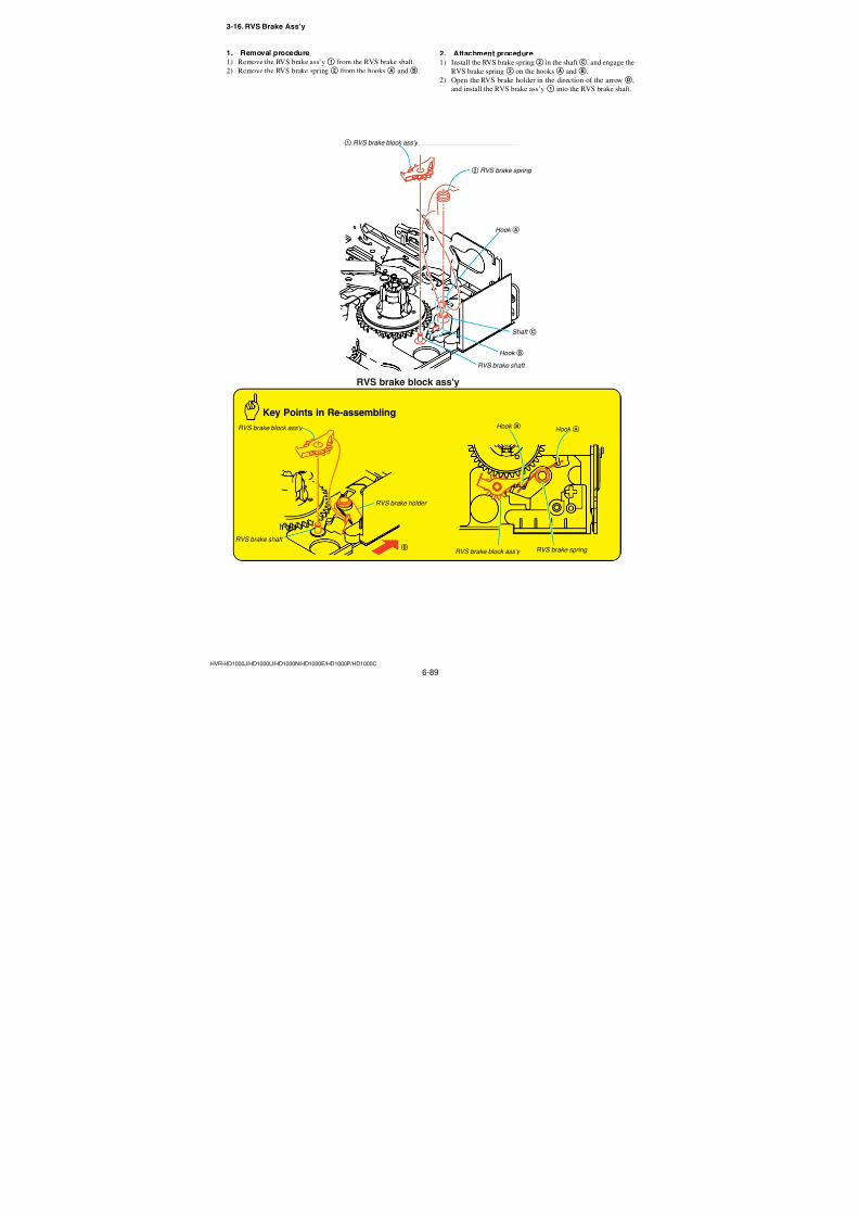
7/18/2019 SONY+HVR-HD1000 SERVICE MANUAL
http://slidepdf.com/reader/full/sonyhvr-hd1000-service-manual 221/4256-73HVR-HD1000J/HD1000U/HD1000N/HD1000E/HD1000P/HD1000C
2-4-3. Mechanism Status (Position) Transition Table Using Mode Selector II
After selecting a mechanism deck, select either the MANUAL orSTEP test (not AUTO) using the Mode Selector II. The desired
mechanism status (position) can be specified by pressing the RVS
or FF button. (The selected status appears on STATUS.)
EJyULEyLD1 (SR)yLD2 (HL)ySTOPyR/P
2-4-4. Battery Alarm IndicationWhen the level of the battery used to supply power to this system
decreases, this display appears asynchronously. When this hap-pens, all operations are disabled and the battery must be replaced.
MD nameCodeA B C
0 1 0
1 1 01 0 0
1 0 1
0 0 1
0 1 1
1
23
4
5
6
N Mechanism (Display: Z)
EJ
ULELD1 (SR)
LD2 (HL)
STOP
R/P
Fig. F
BATT DOWN
CHANGE PLEASE
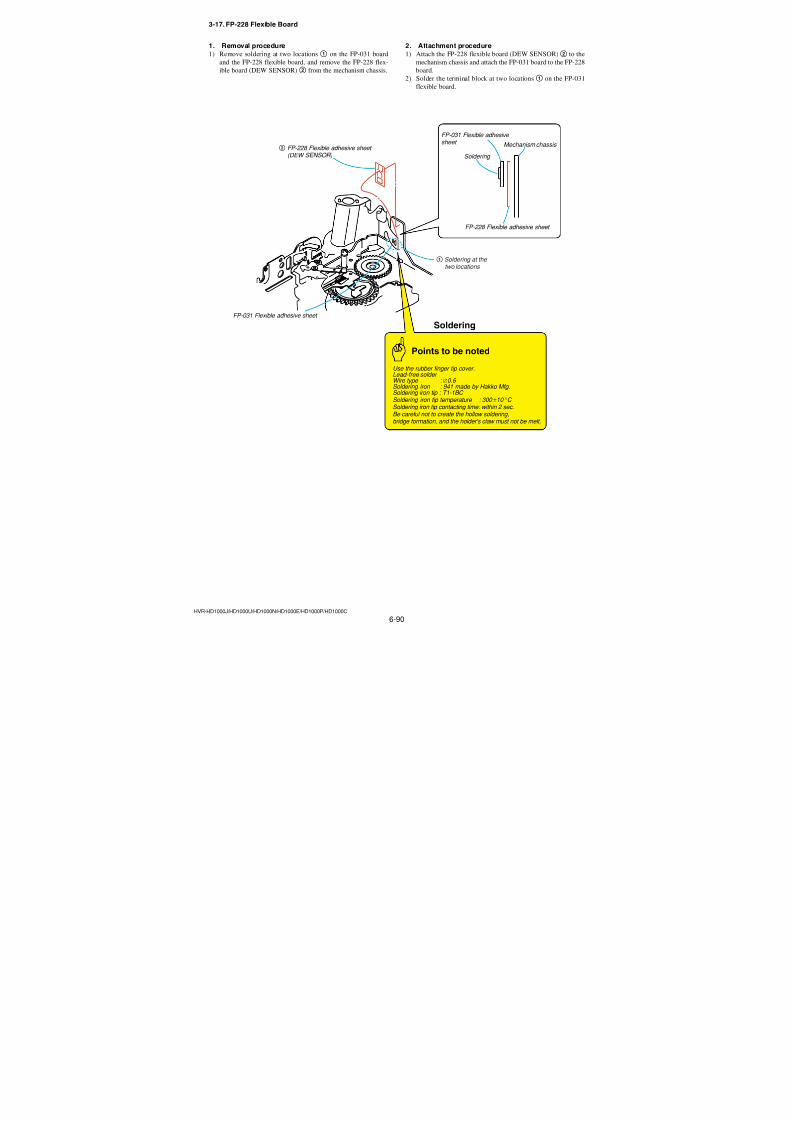
7/18/2019 SONY+HVR-HD1000 SERVICE MANUAL
http://slidepdf.com/reader/full/sonyhvr-hd1000-service-manual 222/4256-74HVR-HD1000J/HD1000U/HD1000N/HD1000E/HD1000P/HD1000C
3. Check, Adjustment and Replacement of Mechanical Parts
3-1. Flowchart of Replacement of Mechanical Parts
HELPHELP
(page 6-78)
(page 6-83)
(page 6-81)
(page 6-86)
(page 6-94)
(page 6-84) (page 6-85)
(page 6-102)
(page 6-80)
(page 6-101)
(page 6-91)
MDX-N210/N220
(page 6-77)
3-4. TG6 Catcher
3-13. S BrakeBlock Ass'y
(page 6-87)
3-14. Tension RegulatorBlock Ass'y
(page 6-82)
3-9. LED (D902)
3-18. TG6 Block Ass'y
(page 6-92)
3-19. Pinch Arm Ass'y
3-10. LED Base
3-21. Drum Base Ass'y
3-25. LS Chassis Block, Mechanism Chassis Block-1 (page 6-98)
3-26. LS Chassis Block, Mechanism Chassis Block-2 (page 6-99)
Mechanical Chassis Block
LS Chassis Block
3-28. Relay Gear,Conversion Gear
3-12. S Positioning
(page 6-93)
3-20. Pendulum Ass'y 3-11. T Reel Table Ass'y
(page 6-88)
3-15. S Reel Table Ass'y
(page 6-97)
3-24. GL Gear (T)
(page 6-79)
3-17. FP-228 Flexible Board
3-7. END Sensor (Q901)
3-27. T Reel Sensor (H902) S Reel Sensor (H901)
(page 6-89)
3-16. RVS Brake Ass'y
3-22. Coaster Ass'y, Rail
(page 6-96)
(page 6-95)
3-23. GL (T) Block Ass'y, GL Arm (S) Ass'y
(page 6-103)
(page 6-104)
3-29. Cam Gear Ass'y
3-30. Mode Slider Ass'y
(page 6-105)
3-31. Cam Gear Ass'y,Mode Gear Ass'y
(page 6-106)
(page 6-90)
3-32. No.1 Gear, No.2 Gear
(page 6-75)
3-2. Drum
(page 6-76)
3-3. Cassette Compartment Ass'y 3-5. Motor Holder Block Ass'y
3-6. L-motor Block Ass'y(Loading), (M902)
3-8. MIC Terminal(MIC903)
Ver. 1.1 2007.12
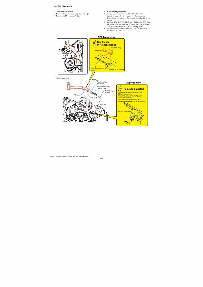
7/18/2019 SONY+HVR-HD1000 SERVICE MANUAL
http://slidepdf.com/reader/full/sonyhvr-hd1000-service-manual 223/4256-75HVR-HD1000J/HD1000U/HD1000N/HD1000E/HD1000P/HD1000C
3-2. Drum
HOW TO PLACETHE MECHANISM
Drum (rear view)
Flexible adhesive sheet attachment position
B
C
D
A
Key Pointsin Re-assembling
Points to be noted
Key Points in Re-assemblingAfter the flexible board is attached to theflexible adhesive sheet, place the flexibleboard, that is folded up, at the rear of the
mechanism chassis to prevent the adheredportion from peeling away.
Cassettecompartmentassy
Don’t re-use the flexibleadhesive sheet.
Pointsto be noted
4 Flexible adhesive sheet
1 Flexible adhesive sheet
Tape supporter block
Reference pin A3 Drum
Reference pin B
Flexible board adhesive portion
Drum base blockassy Flexible adhesive sheet
Attach the flexible adhesive sheet along theouter shape of the drum base block assy.
Attach the flexible board while aligningits side with the outer profile of theflexible adhesive sheet.
Flexible adhesive sheet
Slot(reference A)
Hole (reference B)
Drum (rear view)
2 Three screws (M1.4 × 2.0)
2. Attachment procedure1) Enter the [ULE] mode.
2) Attach the flexible adhesive sheet4.
3) Hold the tape supporter block, and set the reference holes A
and B to the drum base reference pins A and B.
4) Install the the drum 3 with the three screws (special head
screw M1.4 × 2.0)2 in the order of B,C andD. Tightening torque: 0.04 ± 0.01 N•m (0.41 × 0.1 kgf•cm)
5) Attach the portionA of the drum flexible board to the flex-ible adhesive sheet1.
6) Clean the tape path mechanism by referring to Section 2-2.
(Refer to Section “2-2. Tape Path System Cleaning”.)
7) Implement the tape path adjustment. (Refer to Section “4-3.
Tape Path Adjustment”)
1. Removal procedure1) Enter the [ULE] mode.
2) Peel away the portionA of the drum flexible board from the
flexible adhesive sheet1.
3) Remove the three screws (special head screw M1.4 × 2.0)2and remove the drum3.
4) Peel away the flexible adhesive sheet4.(Don’t re-use the flexible adhesive sheet. )
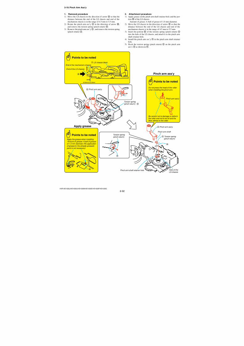
7/18/2019 SONY+HVR-HD1000 SERVICE MANUAL
http://slidepdf.com/reader/full/sonyhvr-hd1000-service-manual 224/4256-76HVR-HD1000J/HD1000U/HD1000N/HD1000E/HD1000P/HD1000C
3-3. Cassette Compartment Ass’y
B
F
G
H
Cassette compartment ass'y
6 Cassette compartment ass'y
Cassette compartmentass'y
Frame 2 Shaft (inside the LS
frame)
1 Three screws
(M1.4 × 4)
4 Shaft (of cassettecompartment ass'y)
5 Shaft (of cassettecompartment ass'y)
3 Shaft (insidethe LS frame)
LS chassis grooveE
LS chassis grooveA
LS chassis grooveC
LS chassis grooveD
Points to be noted
After completing the repair work ,cleanthis side of the cassette compartmentass'y,
1. Removal procedure1) Enter the [EJ] mode.
2) Remove the three screws (special head screw M1.4 × 1.4)1.
3) While pushing the frame of the cassette compartment ass’y
toward inside, remove the shaft 2 inside the LS frame from
the groove A of the LS chassis in the direction of the arrowB.
4) Remove the shaft3 inside the LS frame from the groove C
of the LS chassis.5) Remove the cassette compartment ass’y shafts4 and5 from
the LS chassis groovesD andE. Remove the cassette com-
partment ass’y6.
2. Attachment procedure1) Enter the [ULE] mode.
2) Install cassette compartment ass’y 6 shafts 5 and 4 into
the LS chassis groovesE andD.
3) While pushing the LS frame inward, install the shafts3 and2 inside the LS frame into the grooves C andA of the LS
chassis.4) Install the three screws (special head screw M1.4 × 1.4)1 in
the order ofF,G andH. Tightening torque: 0.06 ± 0.01 N•m (0.61 ± 0.1 kgf•cm)
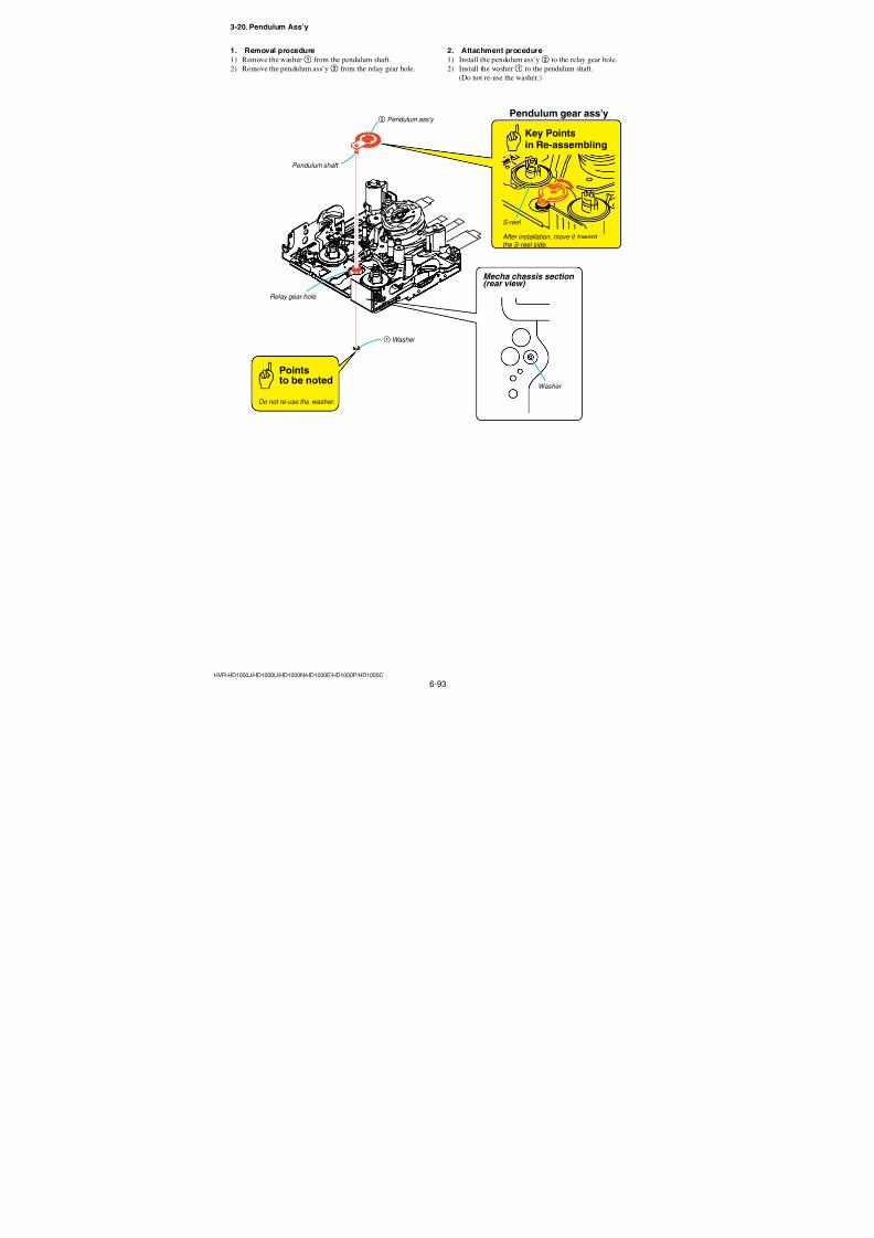
7/18/2019 SONY+HVR-HD1000 SERVICE MANUAL
http://slidepdf.com/reader/full/sonyhvr-hd1000-service-manual 225/4256-77HVR-HD1000J/HD1000U/HD1000N/HD1000E/HD1000P/HD1000C
TG6 catcher
TG6 catcher Chassis
1 TG6 catcher 2 TG6 catcher
HookB
HookC
HookB
HookB
Capstan motorblock
Capstan motorblock
A
3-4. TG6 Catcher
1. Removal procedure1) Disengage the hookB of the TG6 catcher and remove the
TG6 catcher1 from the chassis of the capstan motor block in
the direction of the arrowA.
2. Attachment procedure1) Engage the hooks C and B of the TG6 catcher 2 in the
capstan motor block.
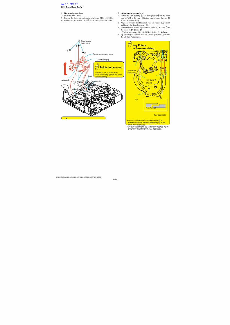
7/18/2019 SONY+HVR-HD1000 SERVICE MANUAL
http://slidepdf.com/reader/full/sonyhvr-hd1000-service-manual 226/4256-78HVR-HD1000J/HD1000U/HD1000N/HD1000E/HD1000P/HD1000C
3-5. Motor Holder Block Ass’y
ClawA
2 FP-031 flexible board
4 Screw ( M1.2 × 1.5 )
3 Screw ( M1.2 × 6.5 )
Points to be noted
Capstan cover
Soldering
• Be careful not to create the hollowsoldering, Br, and the holder's claw mustnot be melt.
• Be careful not to damage the terminaldue to attaching the soldering iron tiptoo long time.
Lead-free solderWire type : ∅0.6 Temperature of the : 320 °Csoldering iron tip
Contacting time of : within 2 sec.
1 Soldering at the two locations
5 Motor holder block ass'y
2. Attachment procedure1) Engage the clawA and install the motor holder block ass’y
(loading) 5.
2) Install the screw (special head screw M1.2 × 1.5)4.
Tightening torque: 0.04 ± 0.01 N•m (0.41 ± 0.1 kgf•cm)
3) Turn over the capstan cover and install the screw (special head
screw M1.2 × 6.5)3.4) Solder the two locations1 and install the FP-031 flexible
board2 to the motor holder block ass’y (loading) 5. Tightening torque: 0.04 ± 0.01 N•m (0.41 ± 0.1 kgf•cm)
1. Removal procedure1) Remove the two soldering1 and remove the FP-031 flexible
board2 from the motor holder block ass’y5.
2) Turn over the capstan cover and remove the screw (special
head screw M1.2 × 6.5)3.
3) Remove the screw (special head screw M1.2 × 1.5)4.
4) Disengage the clawA and motor holder block ass’y5.
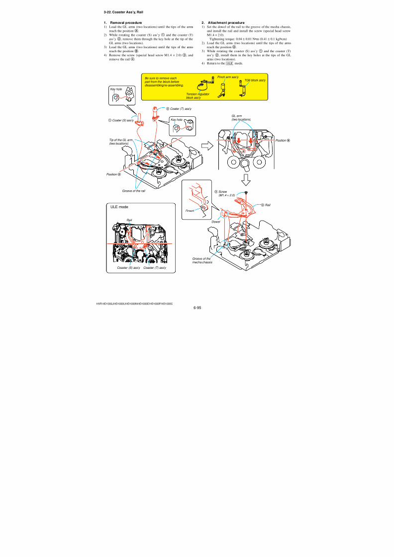
7/18/2019 SONY+HVR-HD1000 SERVICE MANUAL
http://slidepdf.com/reader/full/sonyhvr-hd1000-service-manual 227/4256-79HVR-HD1000J/HD1000U/HD1000N/HD1000E/HD1000P/HD1000C
3-6. L-motor Block Ass’y (Loading) (M902)
D
C
Apply Grease
Worm shaft (2J)
Fixing with screw
Key Points in Re-assembling
Screw
3 Screw (M1.2 × 1.5)
Driver
Hole
Motor worm
4 Motor holder
Motor holder (bottom)
Side of motor worm
Amount of grease application : Grease of a ball of 1.0 mmdiameter (2 locations)
Motor holder Worm shaft (2J)
Key Points in Re-assembling
Points tobe noted
5 L-motor block ass'y (loading) (M902)
DowelB
DowelA
2 Worm shaft (2J)
1 Motor holder base
When fixing with the screw, be careful that the motor worm must not contactwith the screwdriver and screw.
First, insert the portionC of the motorworm into the motor holder's hole.
2. Attachment procedure1) Align the L-motor block ass’y (loading) (M902)5 with the
dowelB, insert it into the motor holder4. While being care-
ful not to contact the screw and the screwdriver with the motor
worm, install the screw (special head screw M1.2 × 1.5)3.
Tightening torque: 0.04 ± 0.01 N•m (0.41 ± 0.1 kgf•cm)
2) Apply the grease as much as a ball of 1.0 mm diameter on theportion D on the bottom of the motor holder 4 and on the
sides of the motor worm.3) Install the worm shaft (2J)2.
4) Engage the dowelA and install the motor holder base1.Note: The motor holder4 and the motor holder base1 must be replaced
simultaneously as a pair.
1. Removal procedure1) Release the dowelA, and remove the motor holder base 1.
2) Remove the worm shaft (2J)2.
3) Remove the screw (special head screw M1.2 × 1.5) 3 and
remove the L-motor block ass’y (loading) (M902)5 from the
motor holder4.
Ver. 1.1 2007.12
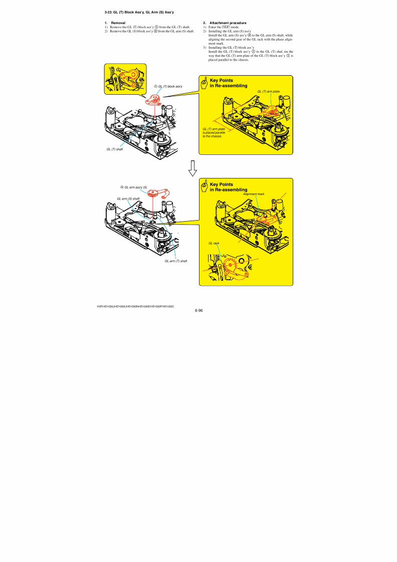
7/18/2019 SONY+HVR-HD1000 SERVICE MANUAL
http://slidepdf.com/reader/full/sonyhvr-hd1000-service-manual 228/4256-80HVR-HD1000J/HD1000U/HD1000N/HD1000E/HD1000P/HD1000C
3-7. END Sensor (Q901)
Soldering
Points to be noted
3 END Sensor (Q901)
2 Claw
5 Claw
4 Two solderings
END Sensor (Q901)
TOP Sensor (Q902)
6 TOP Sensor (Q902)
Two solderingsA
1 Two solderings
FP-031flexible board
FP-031 flexible board
Use the rubber finger tip cover.Lead-free solder Wire type : ∅0.6
Soldering iron : 941 made by Hakko Mfg.Soldering iron tip: T1-1BC
Soldering iron tip temperature : 300 ±10 °C Soldering iron tip contacting time within2 sec.
1. Removal procedure1) Remove soldering at the two locations1 of the END sensor
(Q901).
2) Disengage the claw2 and the END sensor (Q901) 3.
3) Remove soldering at the two locations4 of the TOP sensor
(Q902).
4) Disengage the claw5 and the TOP sensor (Q902)6.
2. Attachment procedure1) Engage the TOP sensor (Q902)6 in the claw5.
2) Solder two locations4 of the TOP sensor (Q902) and install
the TOP sensor (Q902)6 in the FP-031 flexible board.
3) Engage the END sensor (Q901)3 in the claw2.
4) Solder two locations1 of the END sensor (Q901) and install
the END sensor (Q901)3 in the FP-031 flexible board.
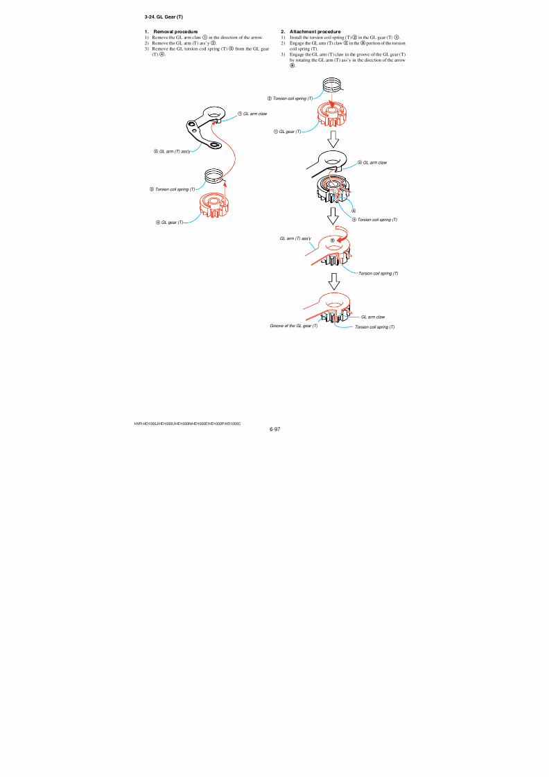
7/18/2019 SONY+HVR-HD1000 SERVICE MANUAL
http://slidepdf.com/reader/full/sonyhvr-hd1000-service-manual 229/4256-81HVR-HD1000J/HD1000U/HD1000N/HD1000E/HD1000P/HD1000C
3-8. MIC terminal (MIC903)
2 FP-031 flexible board
3 Screw ( M1.4 × 2.0 )
1 MIC cover
Position setting hole
MIC cover
Soldering
Points to be noted
Key Points in Re-assembling
MIC terminal (MIC903)
Soldering at the five locationsA 4 MIC terminal (MIC903)
MIC cover
Don't reuse the MIC cover.
Position setting hole
Use the rubber finger tip cover.Lead-free solder Wire type : ∅0.6 Soldering iron : 941 made by Hakko Mfg.Soldering iron tip : T1-1BC Soldering iron tip temperature : 300 ±10 °C Soldering iron tip contacting time: within 2 sec.Be careful not to create the hollow soldering,Br, and the holder's claw must not be melt.
When attaching the MIC cover, alignthe attaching position using the positionsetting hole.
2. Attachment procedure1) While pressing the top of the MIC terminal (MIC903)4, fix
it with the screw (special head screw M1.4 × 2.0)3.
Tightening torque: 0.06 ± 0.01 N•m (0.61 ± 0.1 kgf•cm)
2) Remove soldering at the five locationsA, and install the FP-
031 flexible board2 to the MIC terminal (MIC903)4.
3) Align the position setting hole with the hold and attach theMIC cover.
(Don’t reuse the MIC cover.)
1. Removal procedure1) Enter the [ULE] mode.
2) Peel away the MIC cover1.
3) Remove soldering at the five locationsA, and remove the FP-
031 flexible board2 from the MIC terminal (MIC903)4.
4) Remove the screw (special head screw M1.4 × 2.0) 3, and
remove the MIC terminal (MIC903) 4.
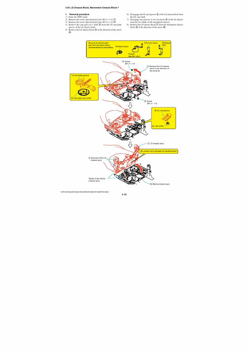
7/18/2019 SONY+HVR-HD1000 SERVICE MANUAL
http://slidepdf.com/reader/full/sonyhvr-hd1000-service-manual 230/4256-82HVR-HD1000J/HD1000U/HD1000N/HD1000E/HD1000P/HD1000C
B
2 LED (D902)
Soldering at 2 locations A
LED (D902)
LED base
• There must be no solder crack.• There must be no scars and no stains.• The flexible board must not have any
breakdown.
• The retainer plate and LED block must nothave any deformation.
1 LED (D902), FP-031 flexible board
FP-031 flexible board
FP-031 flexible board
Direction of the terminal is specified.
Use the rubber finger tip cover.Lead-free solder Wire type : ∅0.6 Soldering iron : 941 made by Hakko Mfg.Soldering iron tip: T1-1BC
Soldering iron tip temperature : 300 ±10 °C
Soldering iron tip contacting time within2 sec.
Soldering
LED (D902),
FP-031 flexible board Points to be noted
Key Pointsin Re-assembling
3-9. LED (D902)
1. Removal procedure1) Remove the LED (D902) and the FP-031 flexible board 1
from the LED base.
2) Remove soldering at the two locationsA, and remove the LED
(D902)2.
2. Attachment procedure1) Remove soldering at the two locationsA, and install the LED
(D902)2 in the FP-031 flexible board.
2) Roll up the FP-031 flexible board under the LED (D902)1with fingertip, and insert the LED top head into the portionBof the LED base. Then route the flexible board in the specified
position.
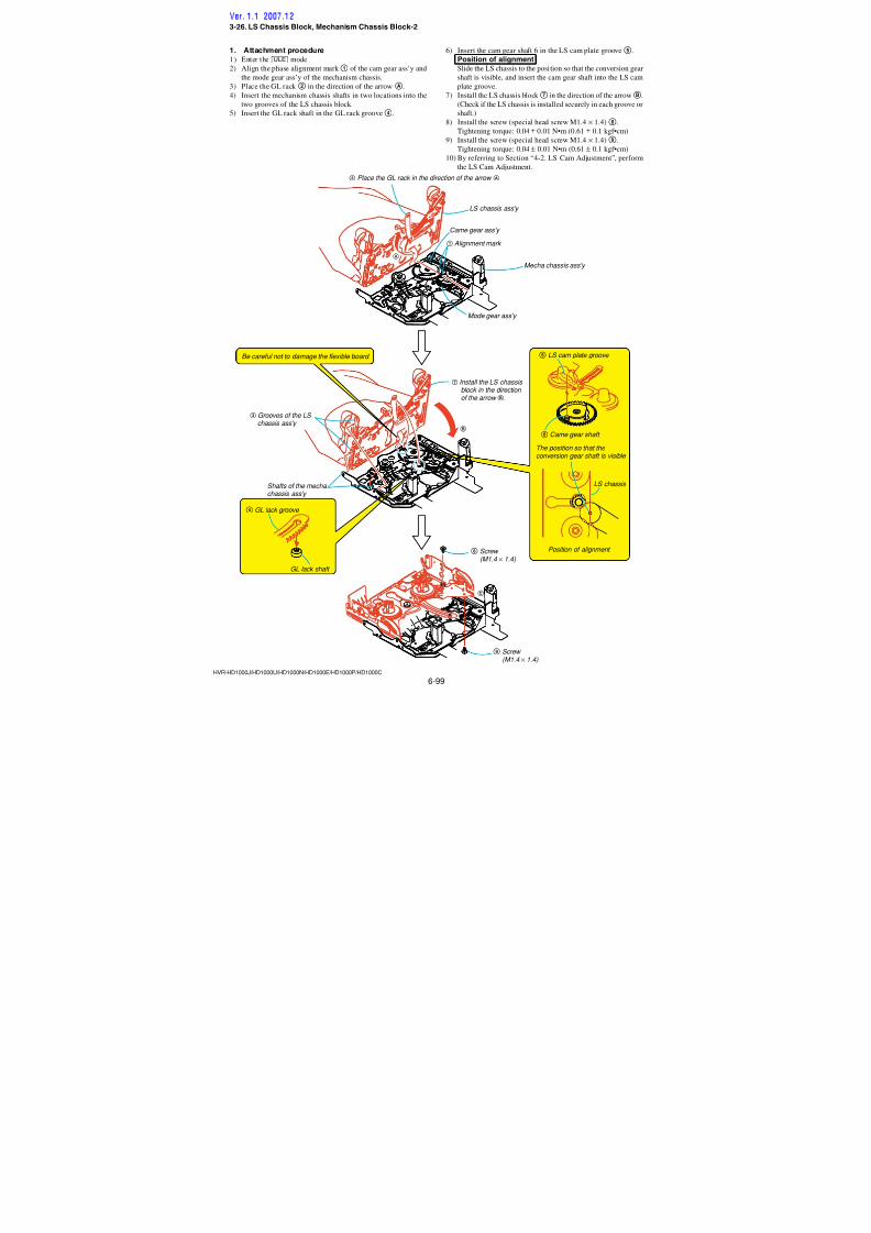
7/18/2019 SONY+HVR-HD1000 SERVICE MANUAL
http://slidepdf.com/reader/full/sonyhvr-hd1000-service-manual 231/4256-83HVR-HD1000J/HD1000U/HD1000N/HD1000E/HD1000P/HD1000C
3-10. LED Base
1 LED (D902)
3 LED base
A
F
4 Reel lock release
• The reel lock release part must not be re-used.• The retainer plate must not have any deformation.• The reel lock release must be full engaged.(Must not be left in the half-installed state.)
Claw E
Claw B
Claw CClaw D
LED
Dowel
Reel lock release LED base
Key Pointsin Re-assembling
Key Pointsin Re-assembling
2 Screw (M1.4 × 1.8)
• All claws must be fully engaged.(Caution : No claws should be left disengaged.)• The flexible board should not be pinched by anything.• The retainer plate must not touch with the MIC terminal.
1. Removal procedure1) Remove the LED (D902)1 from the LED base.
2) Remove the screw (precision screw M1.4 × 1.8)2.
3) Float the LED base3 and remove the dowel.
4) Slide the LED base 3 in the direction of the arrow A, and
disengage the three claws atB,C andD.
5) While freeing the LED from the LED base 3, remove theLED base3.
6) Disengage the clawE and remove the Reel Lock Cancel.
2. Attachment procedure1) Install the Reel Lock Cancel.
2) While passing the LED (D902)1 through the hole of the LED
base3, place the LED base3 on top of the LS chassis.
3) Align the position of the LED base3 first with the clawsBand C, then slide the LED base 3 in the direction of the
arrowF, and engage the three claws B,C andD, and thedowel.
4) Install the screw (precision screw M1.4 × 1.8)2. Tightening torque: 0.04 ± 0.01 N•m (0.41 ± 0.1 kgf•cm)
5) Install the LED (D902)1 to the LED base.
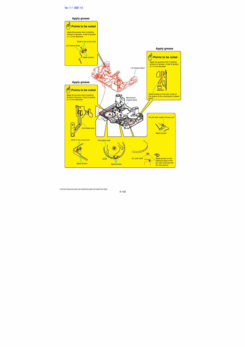
7/18/2019 SONY+HVR-HD1000 SERVICE MANUAL
http://slidepdf.com/reader/full/sonyhvr-hd1000-service-manual 232/4256-84HVR-HD1000J/HD1000U/HD1000N/HD1000E/HD1000P/HD1000C
3-11. T-reel Table Ass’y
1 T reel table ass'y
T reel shaft
T reel shaft
Claw
Claw
1. Removal procedure1) While freeing the claw from the T-reel shaft in the direction of
the arrow, remove the T-reel table ass’y1.
2. Attachment procedure1) Verify that the part that is going to be installed is the T-reel
table ass’y. Then insert it into the T-reel shaft. While rotating
it, snap it in. (Verify that it is locked.)
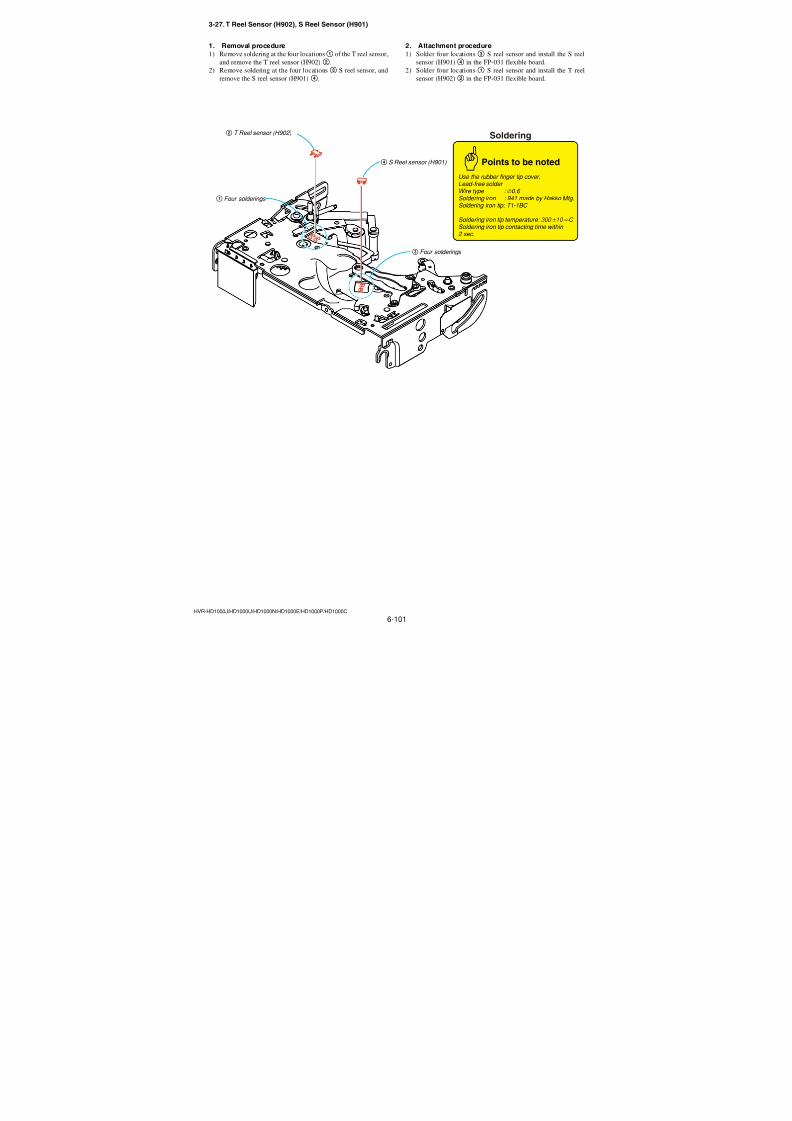
7/18/2019 SONY+HVR-HD1000 SERVICE MANUAL
http://slidepdf.com/reader/full/sonyhvr-hd1000-service-manual 233/4256-85HVR-HD1000J/HD1000U/HD1000N/HD1000E/HD1000P/HD1000C
3-12. S Positioning
1 Extension spring (SB)
Extension spring (SB)(Be careful not to elongate the spring hook.)
2 Hook of the S positioning
5 S positioning
S positioning
S positioning
S brake block ass'y
Claw4
Claw3
Dowel
Key Points in Re-assembling
A
1. Removal procedure1) Remove the tension coil spring (SB)1 from the hook of the S
positioning2.
2) Rotate the S positioning in the direction of the arrowA, and
remove the claw3 and disengage the dowel.
3) Remove the claw4 and remove the S positioning5.
2. Attachment procedure1) Insert the claw4 of the S positioning5 in the hole of the LS
chassis.
2) Engage the claw3 and the dowel.
3) Insert the tension coil spring (SB)1 into the hook of the S
positioning2.
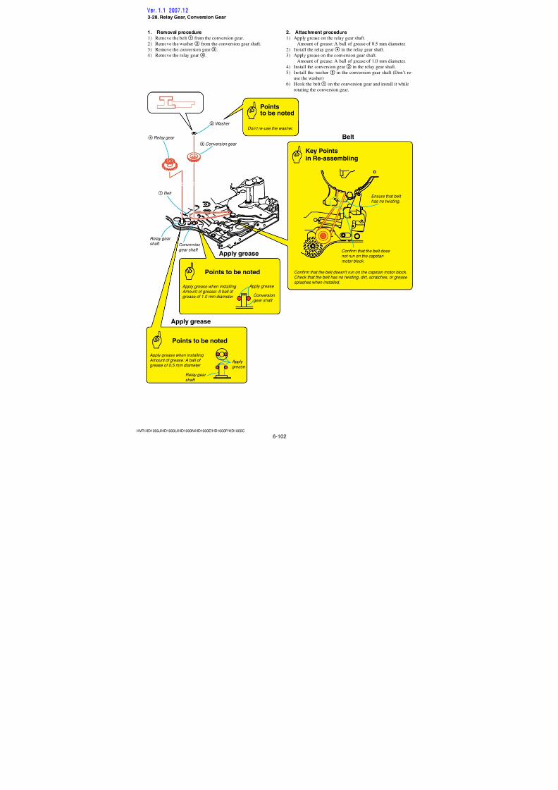
7/18/2019 SONY+HVR-HD1000 SERVICE MANUAL
http://slidepdf.com/reader/full/sonyhvr-hd1000-service-manual 234/4256-86HVR-HD1000J/HD1000U/HD1000N/HD1000E/HD1000P/HD1000C
3-13. S Brake Block Ass’y
1 S brake block ass'y
2 Lever
S brake shaft
S brake block ass'y
Hole of the LS chassis
1. Removal procedure1) Remove the S brake block ass’y1 from the S brake shaft.
2. Attachment procedure1) Insert the lever2 of the S brake block ass’y into the hole of
the LS chassis, and install the S brake block ass’y 1 in the S
brake shaft.
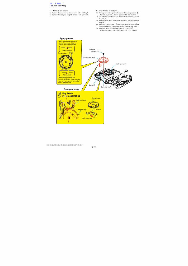
7/18/2019 SONY+HVR-HD1000 SERVICE MANUAL
http://slidepdf.com/reader/full/sonyhvr-hd1000-service-manual 235/4256-87HVR-HD1000J/HD1000U/HD1000N/HD1000E/HD1000P/HD1000C
3-14. Tension Regulator Block Ass’y
Apply grease
Points to be noted
1 Screw (M1.4 × 2.0)
FWD ADJ
S reeltable ass'y
2 Tensionregulator
band
TG1 shaft hole Apply grease inside the hole
of the TG1 shaft hole Amount of grease:A ball of grease of 1.0 mm diameter.(Re-application of grease tothe already-greased-pointis not necessary.)
3 Tension regulatorspring
Groove of thecam base ass'y
TG1 shafthole
TG1 shaft
Hook must facedownward. 4 Tension
regulatorass'y
Tension regulator ass'y
Tension regulator cam lever
Tensionregulatorcam lever
Groove of thecam base ass'y
When installing, insert the tensionregulator cam lever into the grooveof the cam base ass'y.
Key Pointsin Re-assembling
FWD ADJ
Fixing with screw
Tension regulator band
When fixing the screw, press the
FWD ADJ with finger so thatmust not bend the tensionregulator band .
Be careful that the extension regulator band is notscratched or not broken and grease is not attached.
Screwdriver
Points to be noted
2. Attachment procedure1) Apply grease into inside of the TG1 shaft hole.
Amount of grease: A ball of grease of 1.0 mm diameter.
Re-application of grease to the already-greased-point is not
necessary.
2) While inserting the tension regulator cam lever into the groove
of the cam base ass’y, insert the TG1 shaft into the TG1 shafthole.
3) Hook the tension regulator spring3 on the tension regulatorass’y4 with the very end of the spring facing downward.
4) Hook the tension regulator spring3 on the LS chassis.
(The position that is taken a note when it is removed.)
5) Insert the tension regulator band2 into the groove of the S-
reel table ass’y. While pushing the FWD ADJ with finger, fix
it with the screw1 (special head screw M1.4 × 2.0). Tightening torque: 0.06 ± 0.01 N•m (0.61 ± 0.1 kgf•cm)
6) By referring to Section 4-1, perform the TG1 FWD Position
Adjustment.
7) By referring to Section 4-3, perform the FWD Back Tension
Adjustment.Note: Be careful that the extension regulator band is not scratched or
not broken and grease is not attached.
1. Removal procedure1) Remove the screw (special head screw M1.4 × 2.0)1.
2) Remove the tension regulator band2 from the S-reel table
ass’y.
3) Remove the tension regulator spring3.
Note: Take a note where the tension regulator spring.
4) Remove the tension regulator block ass’y4.
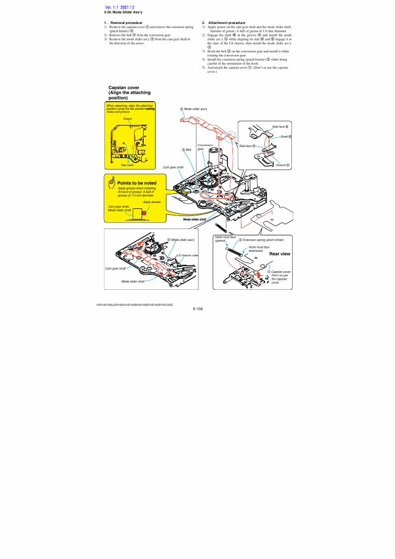
7/18/2019 SONY+HVR-HD1000 SERVICE MANUAL
http://slidepdf.com/reader/full/sonyhvr-hd1000-service-manual 236/4256-88HVR-HD1000J/HD1000U/HD1000N/HD1000E/HD1000P/HD1000C
3-15. S Reel Table Ass’y
3 S reel table ass'y
S reel shaft
Claw
Claw
1 Screw (M1.4 × 2.0)
FWD ADJ
S reel shaft
2 Tensionregulatorband
1. Removal procedure1) Remove the screw (special head screw M1.4 × 2.0)1 .
2) Remove the tension regulator band2 from the S-reel table
ass’y.
3) While freeing the claw at the location in the direction of the
arrow, remove the S-reel table ass’y3 from the S reel shaft.
2. Attachment procedure1) Insert the S-reel table ass’y 3 into the S-reel shaft. While
rotating it, snap it in. (Verify that it is locked.)
2) Insert the tension regulator band into the groove of the S-reel
table ass’y. While pushing the FWD ADJ with finger, fix it
with the screw 1 (special head screw M1.4 × 2.0).
Tightening torque: 0.06 ± 0.01 N•m (0.61 ± 0.1 kgf•cm)
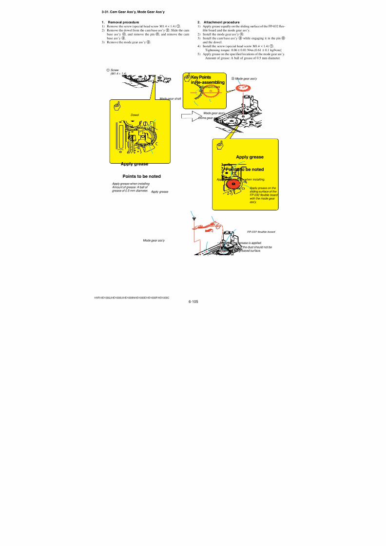
7/18/2019 SONY+HVR-HD1000 SERVICE MANUAL
http://slidepdf.com/reader/full/sonyhvr-hd1000-service-manual 237/4256-89HVR-HD1000J/HD1000U/HD1000N/HD1000E/HD1000P/HD1000C
2 RVS brake spring
HookA
HookB
RVS brake shaft
ShaftC
1 RVS brake block ass'y
RVS brake block ass'y
RVS brake shaft
RVS brake block ass'y
RVS brake holder
RVS brake spring
Key Points in Re-assembling
RVS brake block ass'y
D
HookB HookA
2. Attachment procedure1) Install the RVS brake spring2 in the shaftC, and engage the
RVS brake spring2 on the hooksA andB.
2) Open the RVS brake holder in the direction of the arrowD,and install the RVS brake ass’y1 into the RVS brake shaft.
3-16. RVS Brake Ass’y
1. Removal procedure1) Remove the RVS brake ass’y1 from the RVS brake shaft.
2) Remove the RVS brake spring2 from the hooksA andB.
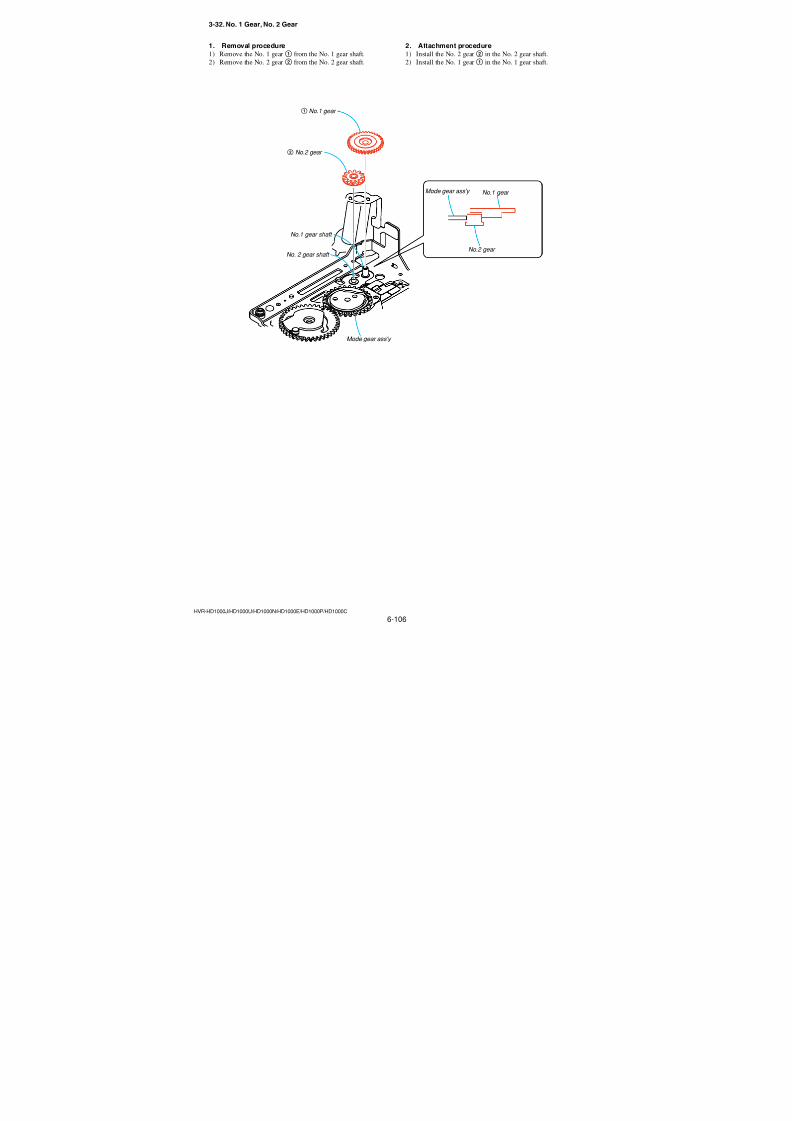
7/18/2019 SONY+HVR-HD1000 SERVICE MANUAL
http://slidepdf.com/reader/full/sonyhvr-hd1000-service-manual 238/4256-90HVR-HD1000J/HD1000U/HD1000N/HD1000E/HD1000P/HD1000C
3-17. FP-228 Flexible Board
2 FP-228 Flexible adhesive sheet (DEW SENSOR)
FP-031 Flexible adhesive sheet
FP-228 Flexible adhesive sheet
FP-031 Flexible adhesivesheet
1 Soldering at thetwo locations
Soldering
Points to be noted
Use the rubber finger tip cover.Lead-free solder Wire type : ∅0.6 Soldering iron : 941 made by Hakko Mfg.Soldering iron tip : T1-1BC Soldering iron tip temperature : 300 ±10 °C Soldering iron tip contacting time: within 2 sec.Be careful not to create the hollow soldering,bridge formation, and the holder's claw must not be melt.
Mechanism chassis
Soldering
1. Removal procedure1) Remove soldering at two locations 1 on the FP-031 board
and the FP-228 flexible board, and remove the FP-228 flex-
ible board (DEW SENSOR)2 from the mechanism chassis.
2. Attachment procedure1) Attach the FP-228 flexible board (DEW SENSOR)2 to the
mechanism chassis and attach the FP-031 board to the FP-228
board.
2) Solder the terminal block at two locations1 on the FP-031
flexible board.
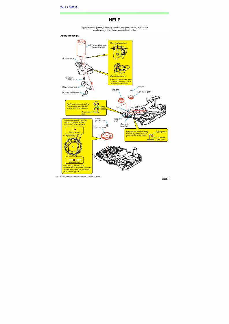
7/18/2019 SONY+HVR-HD1000 SERVICE MANUAL
http://slidepdf.com/reader/full/sonyhvr-hd1000-service-manual 239/4256-91HVR-HD1000J/HD1000U/HD1000N/HD1000E/HD1000P/HD1000C
3-18. TG6 Block Ass’y
2 TG6 block ass'y
1 Extension spring(return TG6)
Key Pointsin Re-assembling
TG6 block ass'y
Apply grease
TG6 block ass'y
Groove of mechanismchassis
Groove of LS chassis
TG6 hole
TG6 lever
TG6 shaft
HookA
Hook must facedownward.
Hook facingoutside.
TG6 pivot shaft boss
Apply grease inside the boss of theTG6 pivot shaft boss.Amount of grease: A ball of greaseof 1.0 mm diameter. (Re-application of grease to thealready-greased-point is not necessary.)
Points to be noted
1. Removal procedure1) Remove the extension spring (return TG6)1.
2) Remove the TG6 block ass’y2.
2. Attachment procedure1) Apply grease inside the boss of the TG6 shaft hole.
Amount of grease: A ball of grease of 1.0 mm diameter.
Re-application of grease to the already-greased-point is not
necessary.
2) Insert the TG6 shaft TG6 block ass’y2 in to the TG6 shaft
hole. At the same time, insert the TG6 shaft lever into the grooveof the LS chassis and that of the mechanism chassis.
3) Engage the extension spring (return TG6)1 on the hookAand hole of the TG6.
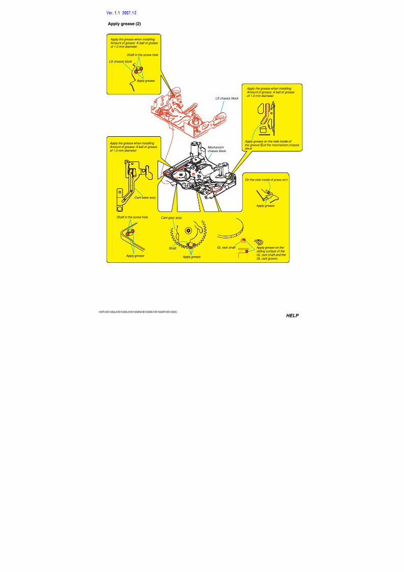
7/18/2019 SONY+HVR-HD1000 SERVICE MANUAL
http://slidepdf.com/reader/full/sonyhvr-hd1000-service-manual 240/4256-92HVR-HD1000J/HD1000U/HD1000N/HD1000E/HD1000P/HD1000C
3-19. Pinch Arm Ass’y
B
A
E
4.5mm to 5.5mm
F
D
Points to be noted
Points to be noted
Points to be noted
Apply grease
Pinch arm ass'y
2 Pinch arm ass'y
1 LS chassis block
End of the LS chassis
End of the mechanism chassis
Pinch arm ass'y
3 Pinch arm ass'y
Pinch arm shaft
Pinch arm shaft retainer hole Hole of the
LS chassis
4 Torsion spring
(pinch return)
Torsion spring
(pinch return) -C
Torsion spring(pinch return)
Do not press the head of the rollerwhen installing the pinch arm.
Be careful not to damage or deformthe roller and not to let oil and thelikes adhere to the roller.
Apply the grease when installing Amount of grease: A ball of greaseof 1.0 mm diameter (Re-applicationof grease to the already-greased- point is not necessary)
1. Removal procedure1) Move the LS chassis in the direction of arrow A so that the
distance between the end of the LS chassis and end of the
mechanism chassis is in the range of 4.5 mm to 5.5 mm.
2) Rotate the pinch arm ass’y 2 in the direction of arrow B,
and remove the torsion spring (pinch return) C.
3) Remove the pinch arm ass’y3 , and remove the torsion spring(pinch return)4.
2. Attachment procedure1) Apply grease on the pinch arm shaft retainer hole and the por-
tionD of the LS chassis.
Amount of grease: A ball of grease of 1.0 mm diameter.
2) Move the LS chassis in the direction of arrowA so that the
distance between the end of the LS chassis and end of the
mechanism chassis is in the range of 4.5 mm to 5.5 mm.3) Insert the portion E of the torsion spring (pinch return) 4
into the hole of the LS chassis, and attach it to the pinch armshaft retainer hole.
4) Install the pinch arm ass’y3 in the pinch arm shaft retainer
hole.
5) Hook the torsion spring (pinch return) 4 on the pinch arm
ass’y3 as shown inF.
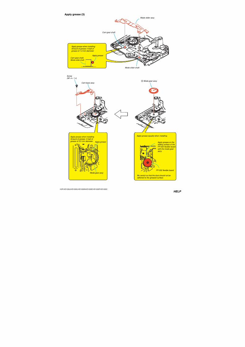
7/18/2019 SONY+HVR-HD1000 SERVICE MANUAL
http://slidepdf.com/reader/full/sonyhvr-hd1000-service-manual 241/4256-93HVR-HD1000J/HD1000U/HD1000N/HD1000E/HD1000P/HD1000C
3-20. Pendulum Ass’y
2 Pendulum ass'y
Pendulum shaft
Pendulum gear ass'y
1 Washer
Washer
S-reel
After installation, move it toward
the S-reel side.
Do not re-use the washer.
Key Pointsin Re-assembling
Mecha chassis section (rear view)
Pointsto be noted
Relay gear hole
1. Removal procedure1) Remove the washer1 from the pendulum shaft.
2) Remove the pendulum ass’y2 from the relay gear hole.
2. Attachment procedure1) Install the pendulum ass’y2 to the relay gear hole.
2) Install the washer1 to the pendulum shaft.
(Do not re-use the washer.)
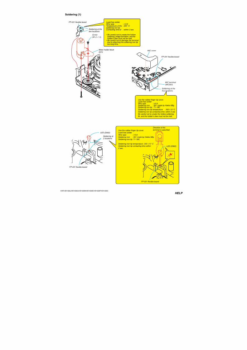
7/18/2019 SONY+HVR-HD1000 SERVICE MANUAL
http://slidepdf.com/reader/full/sonyhvr-hd1000-service-manual 242/4256-94HVR-HD1000J/HD1000U/HD1000N/HD1000E/HD1000P/HD1000C
3-21. Drum Base Ass’y
H
G
F
Points to be noted
Key Pointsin Re-assembling
1 Three screws (M1.4 × 2.0)
Claw D
Claw D
Rail
Groove B
• Be sure that the claws at two locationsC ofthe rail are placed on the claw bearingA of thedrum base block ass'y.
• Be sure that the clawD of the rail is inserted inside
the grooveB
of the drum base block ass'y.
Be careful not to hit the drumbase block ass'y against the guidewhen installing.
Groove B
Two dowels E
Two clawsC
Guide
Claw bearingA
Claw bearingA
Claw bearingA
2 Drum base block ass'y
Drum base block ass'y
Two clawsC
Two clawsC
1. Removal procedure1) Enter the [ULE] mode.
2) Remove the three screws (special head screw M1.4 × 2.0)1.
3) Remove the drum base ass’y2 in the direction of the arrow.
2. Attachment procedure1) Install the claw bearing A and then groove B of the drum
base ass’y2 in the clawsC in two locations and the clawDof the rail, respectively.
2) Align the two dowels of the drum base ass’y at theE position
and install the drum base ass’y2.
3) Install the three screws (special head screw M1.4 × 2.0)1 inthe order ofF,G andH.
Tightening torque: 0.04 ± 0.01 N•m (0.41 ± 0.1 kgf•cm)4) By referring to Section “4-2. LS Cam Adjustment”, perform
the LS Cam Adjustment.
Ver. 1.1 2007.12
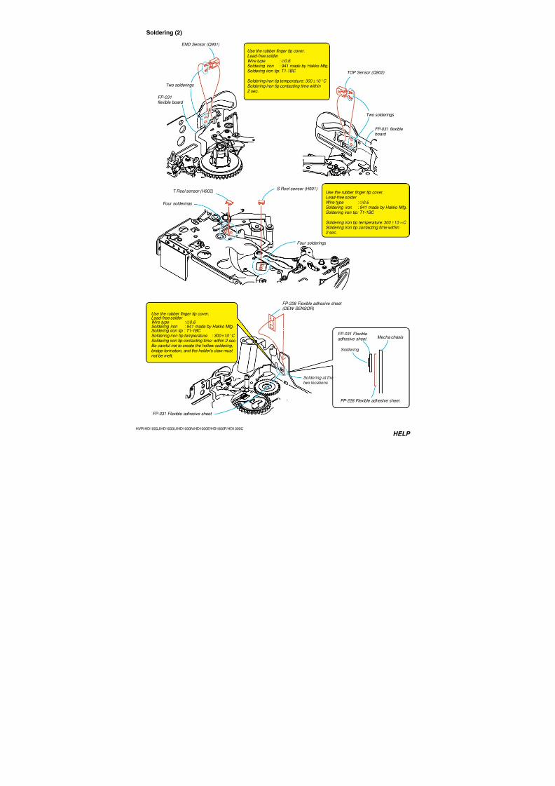
7/18/2019 SONY+HVR-HD1000 SERVICE MANUAL
http://slidepdf.com/reader/full/sonyhvr-hd1000-service-manual 243/4256-95HVR-HD1000J/HD1000U/HD1000N/HD1000E/HD1000P/HD1000C
3-22. Coaster Ass’y, Rail
1 Coater (S) ass'y
2 Coater (T) ass'y
Tip of the GL arm(two locations)
Be sure to remove eachpart from the block beforedisassembling/re-assembling.
Groove of the rail
GL arm(two locations)
Tension regulatorblock ass'y
TG6 block ass'y Pinch arm ass'y
Key hole
Key hole
3 Screw (M1.4 × 2.0)
4 Rail ULE mode
Coaster (S) ass'y Coaster (T) ass'y
Rail
Dowel
Dowel
Groove of themecha chassis
PositionA
PositionB
1. Removal procedure1) Load the GL arms (two locations) until the tips of the arms
reach the positionA.
2) While rotating the coaster (S) ass’y 1 and the coaster (T)
ass’y 2, remove them through the key hole at the tip of the
GL arms (two locations).
3) Load the GL arms (two locations) until the tips of the armsreach the positionB.
4) Remove the screw (special head screw M1.4 × 2.0) 3, andremove the rail4.
2. Attachment procedure1) Set the dowel of the rail to the groove of the mecha chassis,
and install the rail and install the screw (special head screw
M1.4 × 2.0).
Tightening torque: 0.04 ± 0.01 N•m (0.41 ± 0.1 kgf•cm)
2) Load the GL arms (two locations) until the tips of the arms
reach the positionA.3) While rotating the coaster (S) ass’y 1 and the coaster (T)
ass’y 2, install them in the key holes at the tips of the GLarms (two locations).
4) Return to the [ULE] mode.
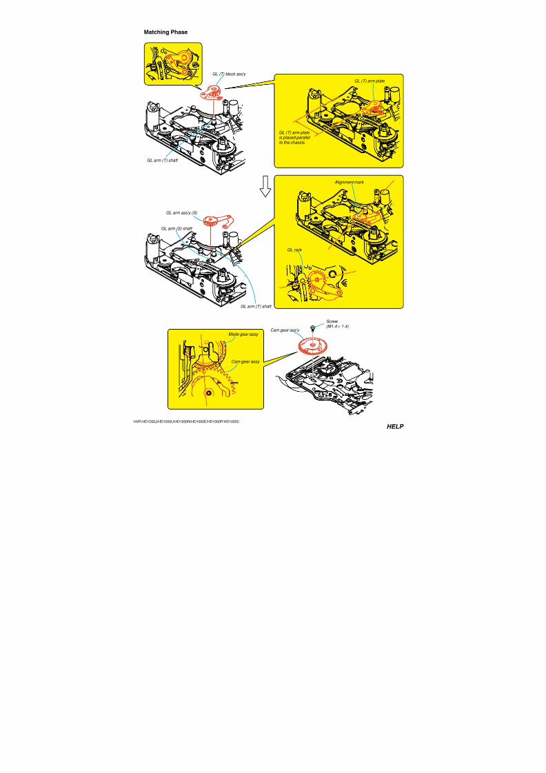
7/18/2019 SONY+HVR-HD1000 SERVICE MANUAL
http://slidepdf.com/reader/full/sonyhvr-hd1000-service-manual 244/4256-96HVR-HD1000J/HD1000U/HD1000N/HD1000E/HD1000P/HD1000C
3-23. GL (T) Block Ass’y, GL Arm (S) Ass’y
Key Pointsin Re-assembling
Key Pointsin Re-assembling
2 GL arm ass'y (S)
GL rack
GL arm (S) shaft
GL (T) shaft
GL arm (T) shaft
GL (T) arm plate
GL (T) arm plateis placed parallelto the chassis.
1 GL (T) block ass'y
Alignment mark
1. Removal1) Remove the GL (T) block ass’y1 from the GL (T) shaft.
2) Remove the GL (S) block ass’y2 from the GL arm (S) shaft.
2. Attachment procedure1) Enter the [ULE] mode.
2) Installing the GL arm (S) ass'y
Install the GL arm (S) ass’y2 to the GL arm (S) shaft, while
aligning the second gear of the GL rack with the phase align-
ment mark.
3) Installing the GL (T) block ass’yInstall the GL (T) block ass’y 1 to the GL (T) shaf, tin the
way that the GL (T) arm plate of the GL (T) block ass’y1 isplaced parallel to the chassis.
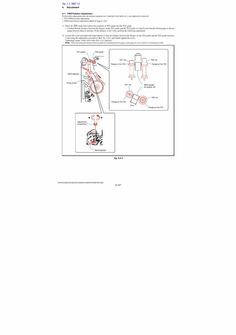
7/18/2019 SONY+HVR-HD1000 SERVICE MANUAL
http://slidepdf.com/reader/full/sonyhvr-hd1000-service-manual 245/4256-97HVR-HD1000J/HD1000U/HD1000N/HD1000E/HD1000P/HD1000C
3-24. GL Gear (T)
1 GL arm claw
GL arm claw
2 GL arm (T) ass'y
GL arm (T) ass'y
3 GL arm claw
4 GL gear (T)
Groove of the GL gear (T)
1 GL gear (T)
3 Torsion coil spring (T)
4 Torsion coil spring (T)
2 Torsion coil spring (T)
Torsion coil spring (T)
Torsion coil spring (T)
B
A
1. Removal procedure1) Remove the GL arm claw1 in the direction of the arrow.
2) Remove the GL arm (T) ass’y2.
3) Remove the GL torsion coil spring (T)3 from the GL gear
(T)4.
2. Attachment procedure1) Install the torsion coil spring (T)2 in the GL gear (T)1.
2) Engage the GL arm (T) claw3 in theA portion of the torsion
coil spring (T).
3) Engage the GL arm (T) claw in the groove of the GL gear (T)
by rotating the GL arm (T) ass’y in the direction of the arrowB.
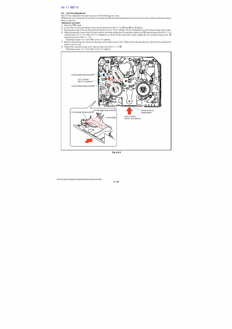
7/18/2019 SONY+HVR-HD1000 SERVICE MANUAL
http://slidepdf.com/reader/full/sonyhvr-hd1000-service-manual 246/4256-98HVR-HD1000J/HD1000U/HD1000N/HD1000E/HD1000P/HD1000C
3-25. LS Chassis Block, Mechanism Chassis Block-1
1 Screw (M1.4 × 1.4)
2 Screw (M1.4 × 1.4)
5 GL rack groove
3 Cam gear ass'y shaft
LS cam plate groove
7 LS chassis ass'y
Be careful not to damage the flexible board.
8 Mecha chassis ass'y
Shafts of the mechachassis ass'y
6 Grooves of the LS chassis ass'y
GL rack shaft
4 Remove the LS chassisblock in the direction of
the arrowA.A
B
Pendulum ass'y
TG6 blockass'y
Tensionregulator ass'y
Pinch arm ass'y Be sure to remove eachpart from the block beforedisassembling/re-assembling.
1. Removal procedure1) Enter the [ULE] mode.
2) Remove the screw (special head screw M1.4 × 1.4)1.
3) Remove the screw (special head screw M1.4 × 1.4)2.
4) Remove the cam gear ass’y shaft3 from the LS cam plate
groove of the LS chassis block.
5) Remove the LS chassis block4 in the direction of the arrowA.
6) Disengage the GL rack groove5 of the LS chassis block from
the GL rack shaft.
7) Disengage the grooves in two locations6 of the LS chassis
from the two shafts of the mechanism chassis.
8) Remove the LS chassis block7 from the mechanism chassis
block8 in the direction of the arrow B.
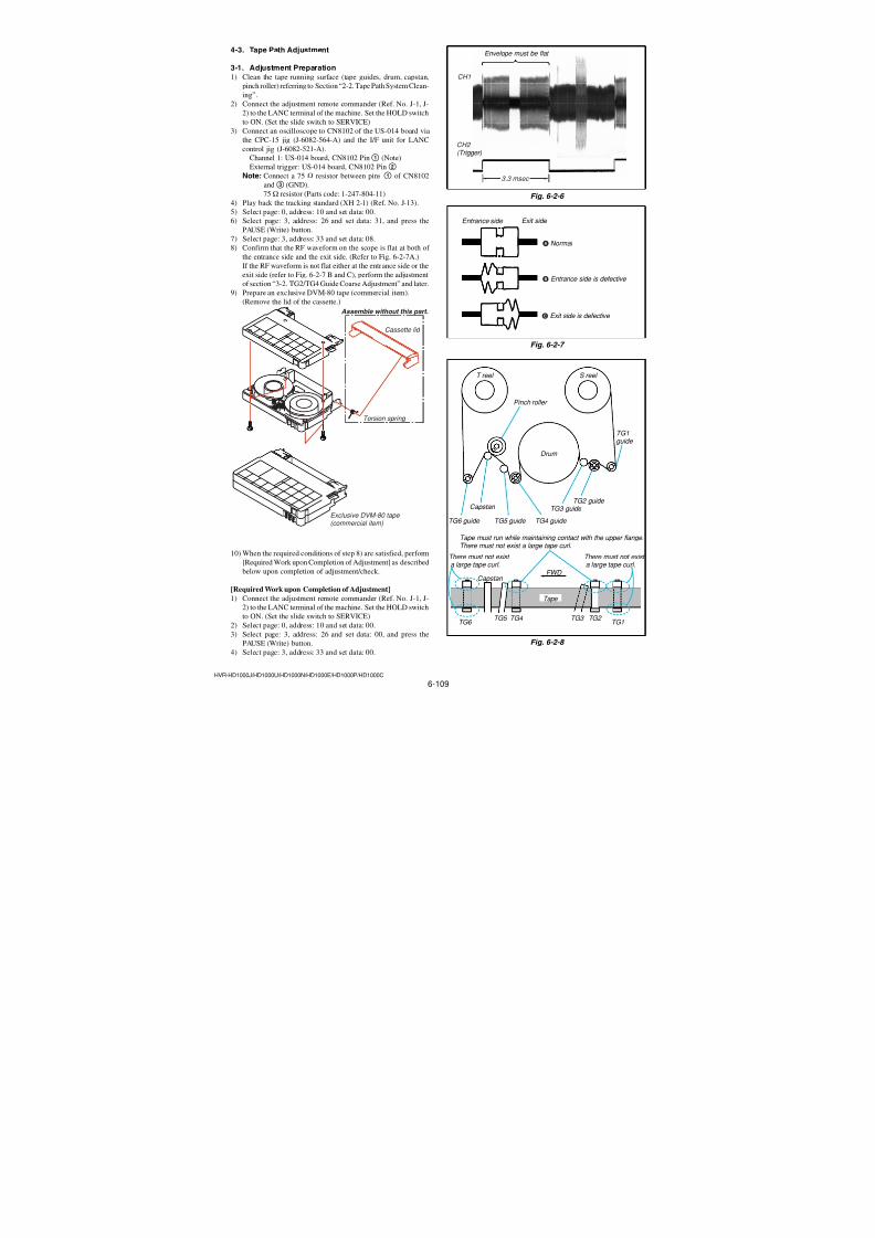
7/18/2019 SONY+HVR-HD1000 SERVICE MANUAL
http://slidepdf.com/reader/full/sonyhvr-hd1000-service-manual 247/4256-99HVR-HD1000J/HD1000U/HD1000N/HD1000E/HD1000P/HD1000C
6) Insert the cam gear shaft 6 in the LS cam plate groove5.
Position of alignmentSlide the LS chassis to the position so that the conversion gear
shaft is visible, and insert the cam gear shaft into the LS cam
plate groove.
7) Install the LS chassis block7 in the direction of the arrowB.
(Check if the LS chassis is installed securely in each groove orshaft.)
8) Install the screw (special head screw M1.4 × 1.4)8.Tightening torque: 0.04 ± 0.01 N•m (0.61 ± 0.1 kgf•cm)
9) Install the screw (special head screw M1.4 × 1.4)9.
Tightening torque: 0.04 ± 0.01 N•m (0.61 ± 0.1 kgf•cm)
10) By referring to Section “4-2. LS Cam Adjustment”, perform
the LS Cam Adjustment.
3-26. LS Chassis Block, Mechanism Chassis Block-2
7 Install the LS chassisblock in the directionof the arrow B.
B
C
A
8 Screw (M1.4 × 1.4)
4 GL lack groove
6 Came gear shaft
5 LS cam plate groove
Came gear ass'y
Mode gear ass'y
GL lack shaft
Mecha chassis ass'y
LS chassis ass'y
2 Place the GL rack in the direction of the arrow A
LS chassis
The position so that theconversion gear shaft is visible
Position of alignment
9 Screw (M1.4 × 1.4)
1 Alignment mark
Shafts of the mecha
chassis ass'y
3 Grooves of the LS chassis ass'y
Be careful not to damage the flexible board.
1. Attachment procedure1) Enter the [ULE] mode.
2) Align the phase alignment mark1 of the cam gear ass’y and
the mode gear ass’y of the mechanism chassis.
3) Place the GL rack2 in the direction of the arrow A.
4) Insert the mechanism chassis shafts in two locations into the
two grooves of the LS chassis block.5) Insert the GL rack shaft in the GL rack groove4.
Ver. 1.1 2007.12
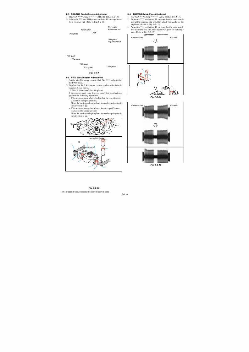
7/18/2019 SONY+HVR-HD1000 SERVICE MANUAL
http://slidepdf.com/reader/full/sonyhvr-hd1000-service-manual 248/4256-100HVR-HD1000J/HD1000U/HD1000N/HD1000E/HD1000P/HD1000C
Apply the grease when installing Amount of grease: A ball of greaseof 1.0 mm diameter
Apply grease on the side inside ofthe groove of the mechanism chassisblock.
Apply grease
Apply the grease when installing
Amount of grease: A ball of greaseof 1.0 mm diameter
Apply the grease when installing Amount of grease: A ball of greaseof 1.0 mm diameter
Apply grease
GL rack shaft
On the side inside of press arm
Mechanismchassis block
LS chassis block
Cam base assy
Shaft in the screw hole
Apply grease on thesliding surface of theGL rack shaft and theGL rack groove.
Cam gear assy
Shaft in the screw hole
LS chassis block
Shaft
Apply grease Apply grease
Points to be noted
Points to be noted
Apply grease
Apply grease
Points to be noted
Apply grease
Ver. 1.1 2007.12
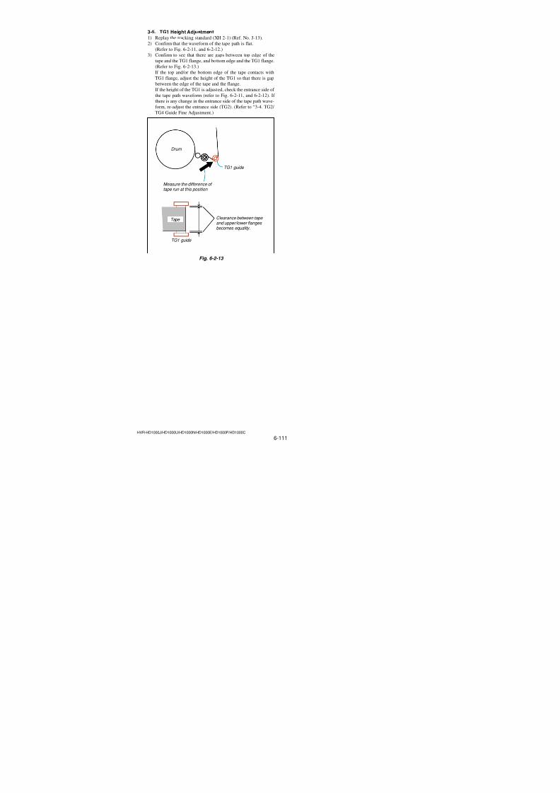
7/18/2019 SONY+HVR-HD1000 SERVICE MANUAL
http://slidepdf.com/reader/full/sonyhvr-hd1000-service-manual 249/4256-101HVR-HD1000J/HD1000U/HD1000N/HD1000E/HD1000P/HD1000C
3-27. T Reel Sensor (H902), S Reel Sensor (H901)
Soldering
Points to be noted
Use the rubber finger tip cover.Lead-free solder Wire type : ∅0.6 Soldering iron : 941 made by Hakko Mfg.Soldering iron tip: T1-1BC
Soldering iron tip temperature : 300 ±10 ∞C Soldering iron tip contacting time within2 sec.
4 S Reel sensor (H901)
2 T Reel sensor (H902)
1 Four solderings
3 Four solderings
1. Removal procedure1) Remove soldering at the four locations1 of the T reel sensor,
and remove the T reel sensor (H902)2.
2) Remove soldering at the four locations 3 S reel sensor, and
remove the S reel sensor (H901) 4.
2. Attachment procedure1) Solder four locations 3 S reel sensor and install the S reel
sensor (H901)4 in the FP-031 flexible board.
2) Solder four locations 1 S reel sensor and install the T reel
sensor (H902)2 in the FP-031 flexible board.
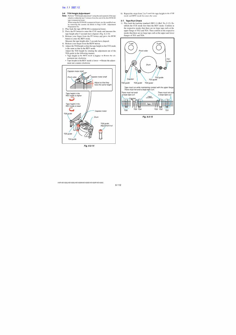
7/18/2019 SONY+HVR-HD1000 SERVICE MANUAL
http://slidepdf.com/reader/full/sonyhvr-hd1000-service-manual 250/4256-102HVR-HD1000J/HD1000U/HD1000N/HD1000E/HD1000P/HD1000C
3-28. Relay Gear, Conversion Gear
Key Points
in Re-assembling
Points to be noted
Points to be noted
Apply grease
Apply grease
Belt
2 Washer
4 Relay gear
3 Conversion gear
Relay gear shaft
Relay gear shaft
Apply grease
Apply grease
Conversiongear shaft
Apply grease when installing Amount of grease: A ball ofgrease of 1.0 mm diameter
Apply grease when installing Amount of grease: A ball ofgrease of 0.5 mm diameter
Conversiongear shaft
Confirm that the belt doesn't run on the capstan motor block.Check that the belt has no twisting, dirt, scratches, or greasesplashes when installed.
Confirm that the belt doesnot run on the capstanmotor block.
Ensure that belthas no twisting.
1 Belt
Don’t re-use the washer.
Pointsto be noted
1. Removal procedure1) Remove the belt1 from the conversion gear.
2) Remove the washer2 from the conversion gear shaft.
3) Remove the conversion gear3.
4) Remove the relay gear4.
2. Attachment procedure1) Apply grease on the relay gear shaft.
Amount of grease: A ball of grease of 0.5 mm diameter.
2) Install the relay gear4 in the relay gear shaft.
3) Apply grease on the conversion gear shaft.
Amount of grease: A ball of grease of 1.0 mm diameter.
4) Install the conversion gear3 in the relay gear shaft.5) Install the washer 2 in the conversion gear shaft (Don’t re-
use the washer)6) Hook the belt1 on the conversion gear and install it while
rotating the conversion gear.
Ver. 1.1 2007.12
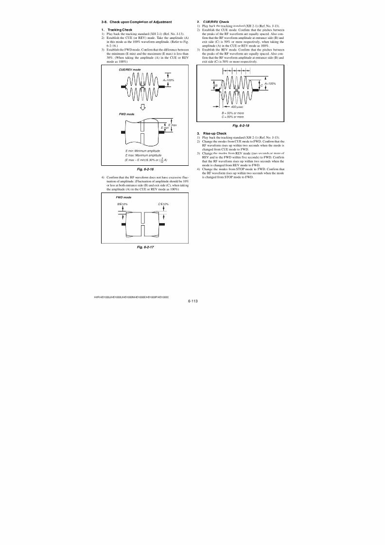
7/18/2019 SONY+HVR-HD1000 SERVICE MANUAL
http://slidepdf.com/reader/full/sonyhvr-hd1000-service-manual 251/4256-103HVR-HD1000J/HD1000U/HD1000N/HD1000E/HD1000P/HD1000C
3-29. Cam Gear Ass’y
Apply grease
Key Pointsin Re-assembling
DowelBCam gear assy
Mode slider assy
1 Screw (M1.4 × 1.4)
2 Cam gear ass'y
Mode gear ass'y
Cam gear assy
Cam gear assy
Mode gear assy
Cam gear shaft
Dowel B
A
Side of inside
Side of outside
Apply grease when installing Amount of grease: A ball ofgrease of 1.0 mm diameter
Cam gear ass'y
Do not apply grease to the
locations other than those specified .Make sure to follow the amount ofgrease to be applied.
1. Removal procedure1) Remove the screw (special head screw M1.4 × 1.4)1.
2) Remove the cam gear ass’y2 from the cam gear shaft.
2. Attachment procedure1) Apply grease on the specified locations of the cam gear ass’y2.
Amount of grease: A ball of grease of 1.0 mm diameter.
2) Move the mode slider ass’y in the direction of arrowA as far
as it can go.
3) Align the gear phase of the mode gear ass’y and the cam gear
ass’y2.4) Install the cam gear ass’y2 while engaging the dowelB of
the mode slider ass’y into the groove of the cam gear ass’y.5) Install the screw (special head screw M1.4 × 1.4)1.
Tightening torque: 0.04 ± 0.01 N•m (0.61 ± 0.1 kgf•cm)
Ver. 1.1 2007.12
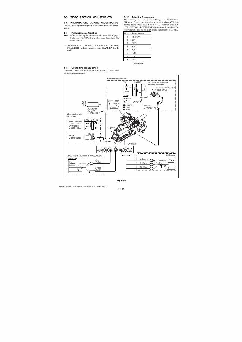
7/18/2019 SONY+HVR-HD1000 SERVICE MANUAL
http://slidepdf.com/reader/full/sonyhvr-hd1000-service-manual 252/4256-104HVR-HD1000J/HD1000U/HD1000N/HD1000E/HD1000P/HD1000C
3-30. Mode Slider Ass’y
Mode slider shaft
setting
Mode slider shaft
Mode slider shaft
LS chassis claw
Cam gear shaft
Cam gear shaft
Cam gear shaft,Mode slider shaft
Apply grease when installing Amount of grease: A ball ofgrease of 1.0 mm diameter
GrooveC
Side faceE
ShaftB
Side faceD
Apply grease
Points to be noted
Rear view
4 Mode slider ass'y
4 Mode slider ass'y
Capstan cover(Align the attachingposition)
Two holes
Dowel
When attaching, align the attachingposition using the two position setting
holes and groove.
Conversiongear 3 Belt
1 Capstan cover Don't re-use
the capstancover
2 Extension spring (pinch limiter)
Hook must facedownward.
Hook must faceupward.
2. Attachment procedure1) Apply grease on the cam gear shaft and the mode slider shaft.
Amount of grease: A ball of grease of 1.0 mm diameter.
2) Engage the shaft B in the groove C and install the mode
slider ass’y4 while aligning its sideD andE engage it in
the claw of the LS chassis, then install the mode slider ass’y4.
3) Hook the belt3 on the conversion gear and install it while
rotating the conversion gear.4) Install the extension spring (pinch limiter)2 while being
careful of the orientation of the hook.
5) And attach the capstan cover1. (Don’t re-use the capstan
cover.)
1. Removal procedure1) Remove the capstan cover1 and remove the extension spring
(pinch limiter)2.
2) Remove the belt3 from the conversion gear.
3) Remove the mode slider ass'y4 from the cam gear shaft in
the direction of the arrow.
Ver. 1.1 2007.12
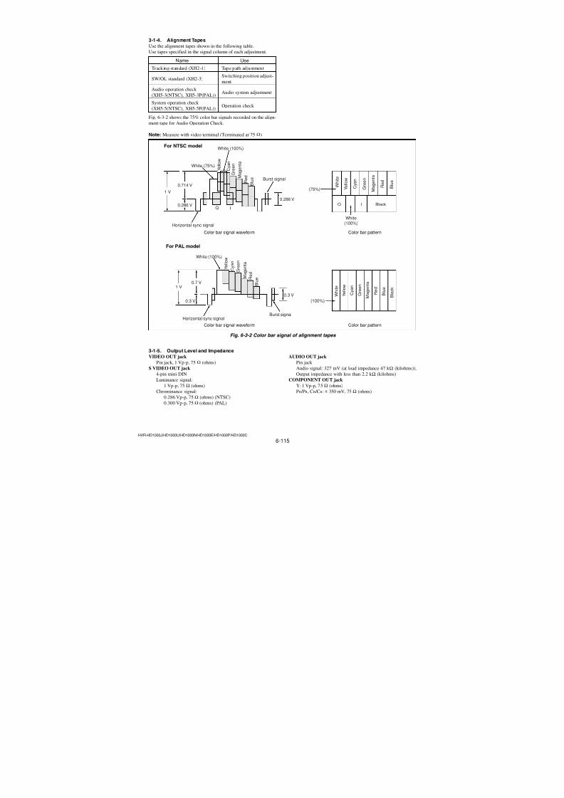
7/18/2019 SONY+HVR-HD1000 SERVICE MANUAL
http://slidepdf.com/reader/full/sonyhvr-hd1000-service-manual 253/4256-105HVR-HD1000J/HD1000U/HD1000N/HD1000E/HD1000P/HD1000C
3-31. Cam Gear Ass’y, Mode Gear Ass’y
1 Screw (M1.4 × 1.4)
2 Cam base ass'y
Mode gear shaft
Apply grease when installing Amount of grease: A ball ofgrease of 0.5 mm diameter.
Apply grease equally when installing.
Apply grease on thesliding surface of theFP-032 flexible boardwith the mode gearass'y.
FP-032 flexible board
• Be careful so that the dust should not beadhered to the greased surface.
• After cleaning, grease is applied.
3 Mode gear ass'y
Mode gear ass'y
Come gear ass'y Dowel
Apply grease
Apply grease
Mode gear ass'y
Apply grease
Points to be noted
Points to be noted
Key Pointsin Re-assembling
Alignment mark
1. Removal procedure1) Remove the screw (special head screw M1.4 × 1.4)1.
2) Remove the dowel from the cam base ass’y2. Slide the cam
base ass’y 2, and remove the pin C, and remove the cam
base ass’y2.
3) Remove the mode gear ass’y3.
2. Attachment procedure1) Apply grease equally on the sliding surface of the FP-032 flex-
ible board and the mode gear ass’y.
2) Install the mode gear ass’y3.
3) Install the cam base ass’y2 while engaging it in the pinCand the dowel.
4) Install the screw (special head screw M1.4 × 1.4)1. Tightening torque: 0.06 ± 0.01 N•m (0.61 ± 0.1 kgf•cm))
5) Apply grease on the specified locations of the mode gear ass’y. Amount of grease: A ball of grease of 0.5 mm diameter.
7/18/2019 SONY+HVR-HD1000 SERVICE MANUAL
http://slidepdf.com/reader/full/sonyhvr-hd1000-service-manual 254/4256-106HVR-HD1000J/HD1000U/HD1000N/HD1000E/HD1000P/HD1000C
3-32. No. 1 Gear, No. 2 Gear
1 No.1 gear
No.1 gear
No.2 gear
2 No.2 gear
Mode gear ass'y
Mode gear ass'y
No.1 gear shaft
No. 2 gear shaft
1. Removal procedure1) Remove the No. 1 gear1 from the No. 1 gear shaft.
2) Remove the No. 2 gear2 from the No. 2 gear shaft.
2. Attachment procedure1) Install the No. 2 gear2 in the No. 2 gear shaft.
2) Install the No. 1 gear1 in the No. 1 gear shaft.
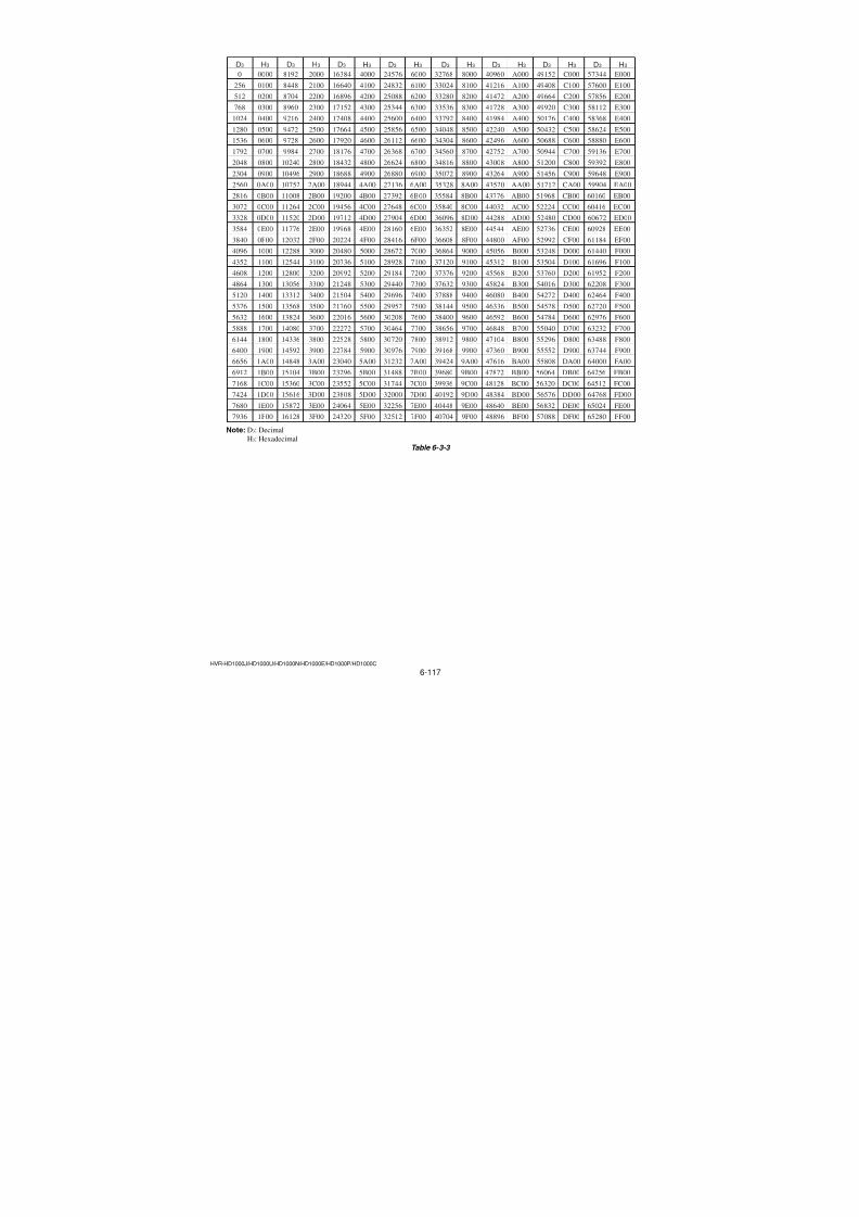
7/18/2019 SONY+HVR-HD1000 SERVICE MANUAL
http://slidepdf.com/reader/full/sonyhvr-hd1000-service-manual 255/425
HVR-HD1000J/HD1000U/HD1000N/HD1000E/HD1000P/HD1000C
HELP
HELP
Apply grease (1)
Application of grease, soldering method and precautions, and phasematching adjustment are compiled and below.
D
3 Screw (M1.2 × 1.5)
4 Motor holder
Motor holder (bottom)
Side of motor worm
Amount of grease application : Grease of a ball of 1.0 mmdiameter (2 locations)
5 L-motor block ass'y (loading) (M902)
2 Worm shaft (2J)
1 Motor holder base
Washer
Relay gear Conversion gear
Relay gear shaft
Relay gear shaft
Conversiongear shaft
Apply grease
Apply grease
Apply grease when installing Amount of grease: A ball ofgrease of 1.0 mm diameter
Apply grease when installing Amount of grease: A ball ofgrease of 0.5 mm diameter
Conversiongear shaft
Belt
Side of inside
Side of outside
Apply grease when installing Amount of grease: A ball ofgrease of 1.0 mm diameter
Cam gear ass'y
Cam gear ass'y
Do not apply grease to thelocations other than those specified .Make sure to follow the amount ofgrease to be applied.
Screw (M1.4 × 1.4)
Ver. 1.1 2007.12
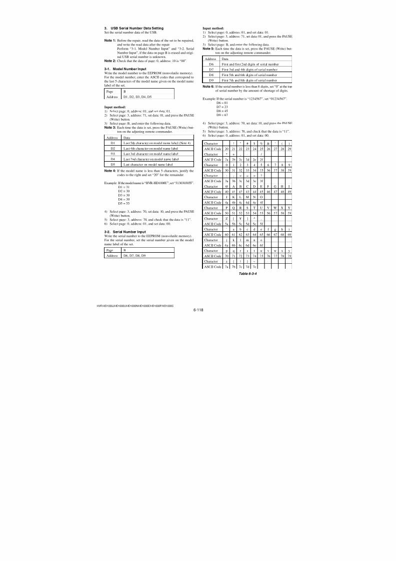
7/18/2019 SONY+HVR-HD1000 SERVICE MANUAL
http://slidepdf.com/reader/full/sonyhvr-hd1000-service-manual 256/425
HVR-HD1000J/HD1000U/HD1000N/HD1000E/HD1000P/HD1000C
HELP
Apply grease (2)
Apply the grease whan installingAmount of grease: A ball of greaseof 1.0 mm diameter
Apply grease on the side inside ofthe grooveCof the mechanism chassisblock.
Apply grease
Apply the grease when installing Amount of grease: A ball of greaseof 1.0 mm diameter
Apply the grease when installing Amount of grease: A ball of greaseof 1.0 mm diameter
Apply grease
GL rack shaft
On the side inside of press arm
Mechanismchassis block
LS chassis block
Cam base assy
Shaft in the screw hole
Apply grease on thesliding surface of theGL rack shaft and theGL rack groove.
Cam gear assy
Shaft in the screw hole
LS chassis block
Shaft
Apply grease Apply grease
Ver. 1.1 2007.12
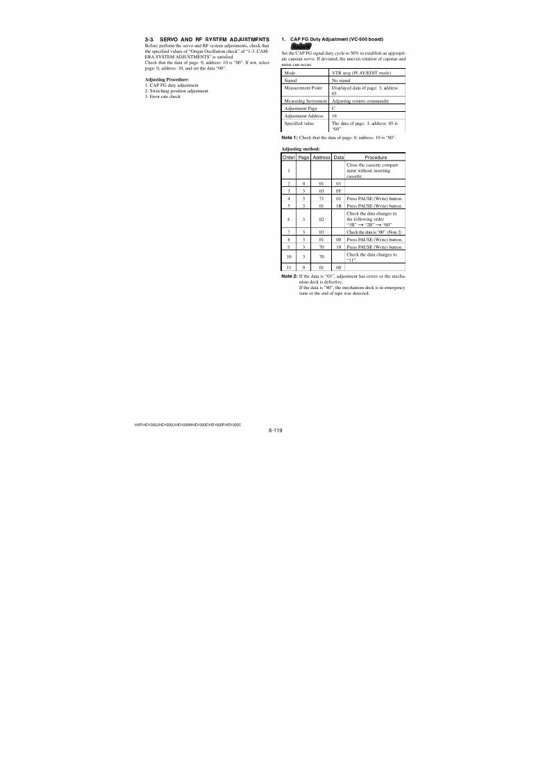
7/18/2019 SONY+HVR-HD1000 SERVICE MANUAL
http://slidepdf.com/reader/full/sonyhvr-hd1000-service-manual 257/425
HVR-HD1000J/HD1000U/HD1000N/HD1000E/HD1000P/HD1000C
HELP
Apply grease (3)Mode slider assy
Mode slider shaft
Cam gear shaft
Apply grease when installing Amount of grease: A ball ofgrease of 1.0 mm diameter
Apply grease
Cam gear shaft,Mode slide shaft
Screw (M1.4 × 1.4)
Cam base assy
Apply grease when installing
Amount of grease: A ball ofgrease of 0.5 mm diameter.
Apply grease equally when installing.
Apply grease on thesliding surface of theFP-032 flexible boardwith the mode gearass'y.
FP-032 flexible board
Be careful so that the dust should not beadhered to the greased surface.
3 Mode gear assy
Apply grease
Mode gear assy
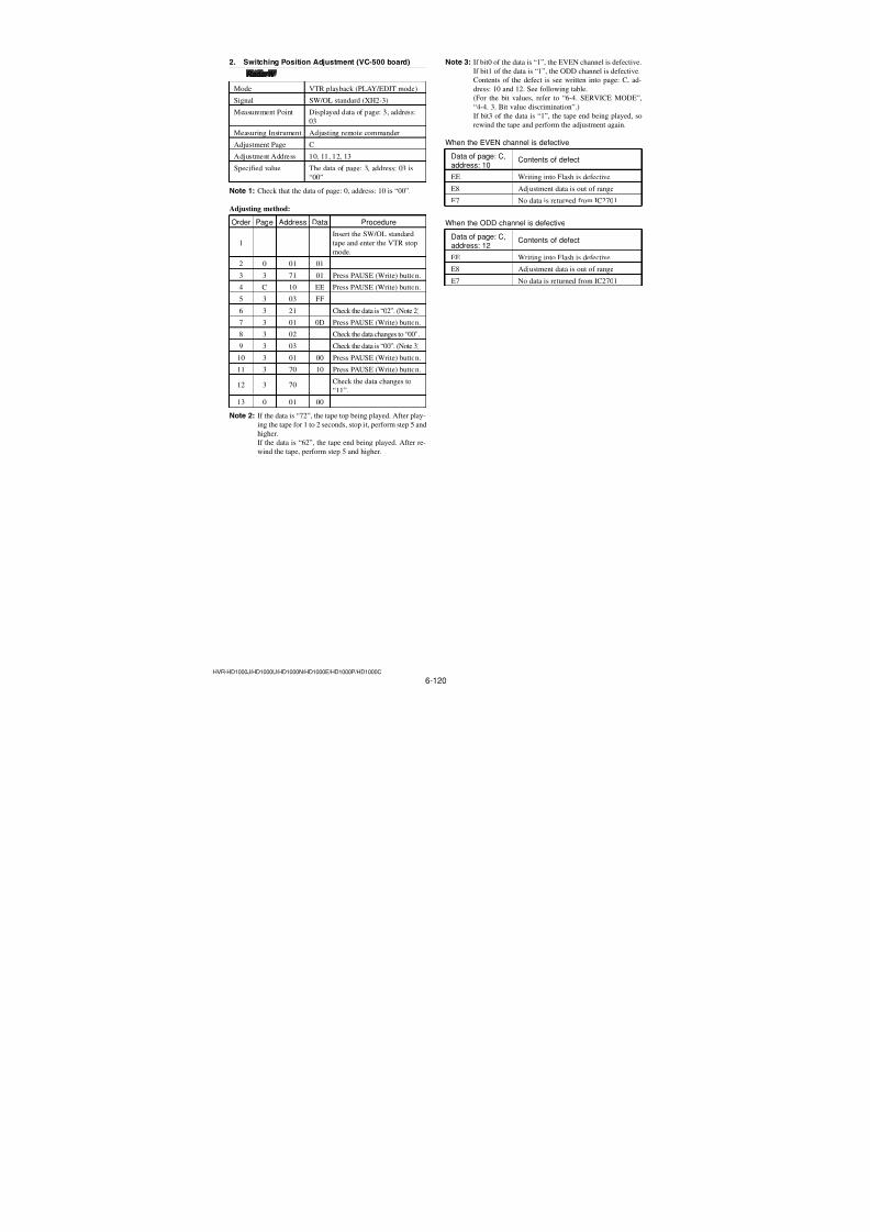
7/18/2019 SONY+HVR-HD1000 SERVICE MANUAL
http://slidepdf.com/reader/full/sonyhvr-hd1000-service-manual 258/425
HVR-HD1000J/HD1000U/HD1000N/HD1000E/HD1000P/HD1000C
HELP
Soldering (1)
FP-031 flexible board
Screw ( M1.2 × 1.5 )
• Be careful not to create the hollowsoldering, bridge formation, and theholder's claw must not be melt.
• Be careful not to damage the terminaldue to attaching the soldering iron tiptoo long time.
Lead-free solderWire type : ∅0.6 Temperature of the : 320 °Csoldering iron tip Contacting time of : within 2 sec.Soldering at the
two locations
Motor holder block ass'y
FP-031 flexible board
MIC cover
MIC terminal (MIC903)
Soldering at thefive locations
Use the rubber finger tip cover.Lead-free solder Wire type : ∅0.6 Soldering iron : 941 made by Hakko Mfg.Soldering iron tip : T1-1BC Soldering iron tip temperature : 300 ±10 °C Soldering iron tip contacting time: within 2 sec.Be careful not to create the hollow soldering,Br, and the holder's claw must not be melt.
LED (D902)
Soldering at2 locations
LED (D902)
FP-031 flexible board
FP-031 flexible board
Direction of theterminal is specified.Use the rubber finger tip cover.
Lead-free solder Wire type : ∅0.6 Soldering iron : 941 made by Hakko Mfg.
Soldering iron tip: T1-1BC
Soldering iron tip temperature : 300 ±10 °C Soldering iron tip contacting time within2 sec.
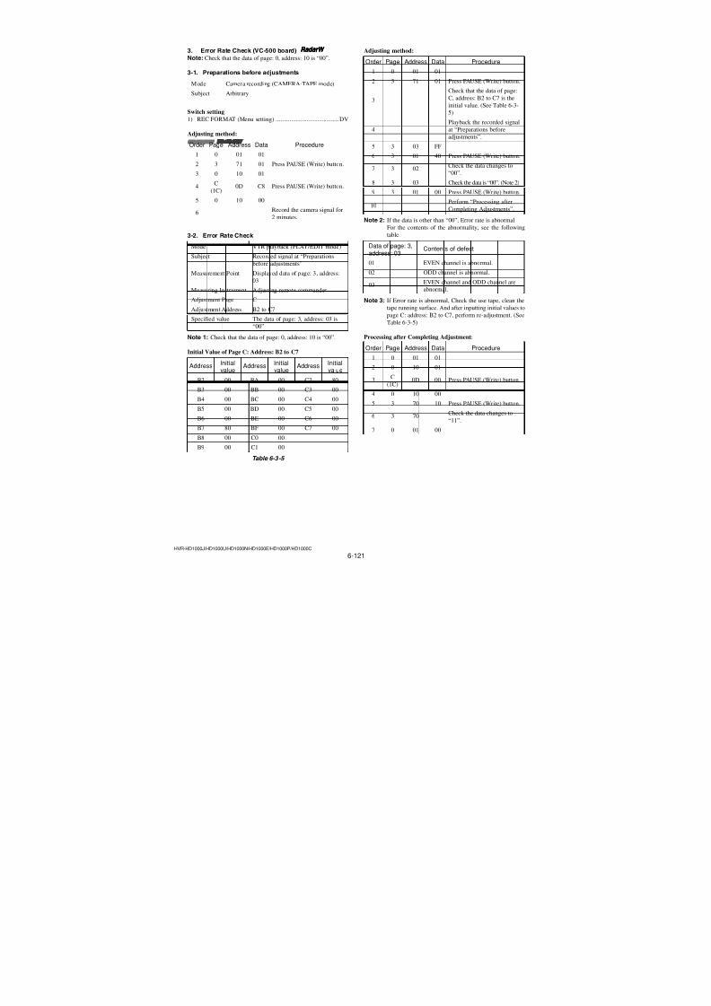
7/18/2019 SONY+HVR-HD1000 SERVICE MANUAL
http://slidepdf.com/reader/full/sonyhvr-hd1000-service-manual 259/425
HVR-HD1000J/HD1000U/HD1000N/HD1000E/HD1000P/HD1000C
HELP
Soldering (2)
END Sensor (Q901)
Two solderings
FP-031flexible board
Use the rubber finger tip cover.Lead-free solder Wire type : ∅0.6 Soldering iron : 941 made by Hakko Mfg.Soldering iron tip: T1-1BC
Soldering iron tip temperature : 300 ±10 °C Soldering iron tip contacting time within2 sec.
TOP Sensor (Q902)
FP-031 flexibleboard
Two solderings
Use the rubber finger tip cover.Lead-free solder Wire type : ∅0.6 Soldering iron : 941 made by Hakko Mfg.Soldering iron tip: T1-1BC
Soldering iron tip temperature : 300 ±10 ∞C Soldering iron tip contacting time within2 sec.
Four solderings
S Reel sensor (H901)T Reel sensor (H902)
Four solderings
FP-228 Flexible adhesive sheet (DEW SENSOR)
FP-228 Flexible adhesive sheet
FP-031 Flexibleadhesive sheet
FP-031 Flexible adhesive sheet
Mecha chasis
Soldering at thetwo locations
Soldering
Use the rubber finger tip cover.Lead-free solder Wire type : ∅0.6 Soldering iron : 941 made by Hakko Mfg.Soldering iron tip : T1-1BC Soldering iron tip temperature : 300 ±10 °C Soldering iron tip contacting time: within 2 sec.Be careful not to create the hollow soldering,bridge formation, and the holder's claw mustnot be melt.
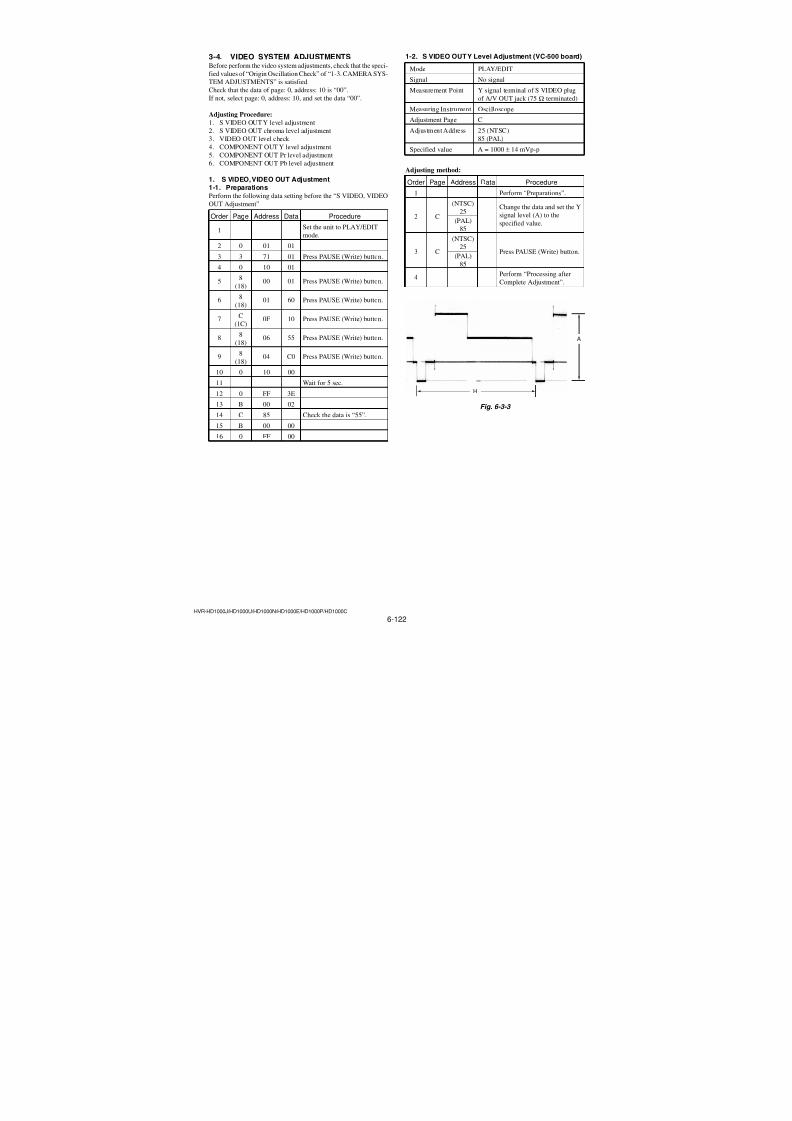
7/18/2019 SONY+HVR-HD1000 SERVICE MANUAL
http://slidepdf.com/reader/full/sonyhvr-hd1000-service-manual 260/425
HVR-HD1000J/HD1000U/HD1000N/HD1000E/HD1000P/HD1000C
HELP
Matching Phase
GL arm ass'y (S)
GL rack
GL arm (S) shaft
GL arm (T) shaft
GL arm (T) shaft
GL (T) arm plate
GL (T) arm plateis placed parallelto the chassis.
GL (T) block ass'y
Alignment mark
Screw (M1.4 × 1.4)
Cam gear ass'y
Cam gear assy
Mode gear assy
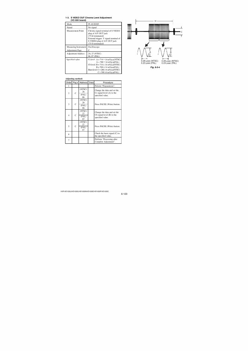
7/18/2019 SONY+HVR-HD1000 SERVICE MANUAL
http://slidepdf.com/reader/full/sonyhvr-hd1000-service-manual 261/4256-107HVR-HD1000J/HD1000U/HD1000N/HD1000E/HD1000P/HD1000C
4. Adjustment
4-1. FWD Position AdjustmentPerform this adjustment after the tension regulator ass’y and the S-reel table ass’y are replaced or removed.
• TG1 FWD position adjustment
• FWD back tension adjustment (Refer to Page 6-110).
1) Enter the [R/P] mode and confirm the positions of TG1 guide and the TG2 guide.
• Confirm that the distance between the flanges on the TG1 guide and the TG2 guide is 2 mm by inserting the block gauge or the pingauge between them to measure. If the distance is not 2 mm, perform the following adjustment.
2) Loosen the screw and adjust the band adjuster so that the distance between the flanges on the TG1 guide and the TG2 guide becomes
2 mm using the adjustment screwdriver (Ref. No. J-24), and finally tighten the screw.
Tightening torque: 0.06 ± 0.01 N•m (0.61 ± 0.1 kgf•cm)Note: When measuring the distance between guides by inserting the block gauge or pin gauge, be very careful not to damage the roller.
Fig. 6-2-4
Band adjuster
TG1 guide TG2 guide
TG1 nut
TG2 nut TG1 nut
Flange on the TG1 Flange on the TG1
TG2 nut
Block gauge,pin gauge, etc
2mm
2mm
Flange on the TG1
Flange on the TG1
Fixing screw
Adjustmentscrewdriver
Band adjuster
Ver. 1.1 2007.12
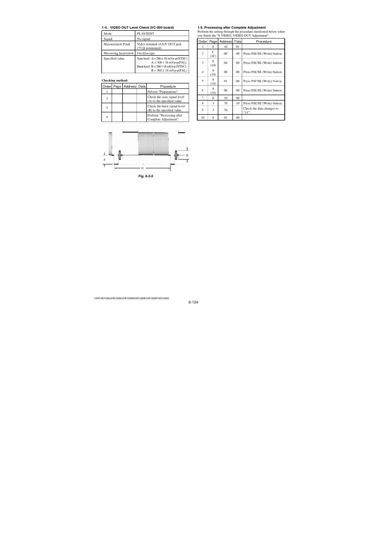
7/18/2019 SONY+HVR-HD1000 SERVICE MANUAL
http://slidepdf.com/reader/full/sonyhvr-hd1000-service-manual 262/4256-108HVR-HD1000J/HD1000U/HD1000N/HD1000E/HD1000P/HD1000C
4-2. LS Cam AdjustmentThe LS Cam Adjustment becomes necessary in the following two cases;1When the screw fixing the LS cam plate is loosened, and2 when the docking between the LS chassis block and the mechanism chassis
block is removed.
Adjustment procedure
1) Enter the [R/P] mode.
2) Loosen the LS cam plate fixing screws (special head screw M1.4 × 1.4)A andB by 90 degrees.
3) Pressing the center of the LS chassis block with the force of 15.0 ± 2.0N•m (153.0 ± 25.0kgf •cm) (as shown by the large arrow mark).
4) While pressing the center of the LS chassis block, and while pulling the LS cam plate fixing screwA (special head screw M1.4 × 1.4)with the force of 2.5 ± 0.5 N•m (25.5 ± 2.5kgf •cm) (as shown by the small arrow mark), tighten the LS cam plate fixing screw A(special head screw M1.4 × 1.4).
Tightening torque: 0.1 ± 0.01 N•m (1.02 ± 0.1 kgf •cm)5) Remove the pressing force shown by the large arrow mark in step 3) first. Then remove the pressing force shown by the small arrow
mark in step 4), next.
6) Tighten the cam plate fixing screw (special head screw M1.4 × 1.4)B.
Tightening torque: 0.1 ± 0.01 N•m (1.02 ± 0.1 kgf •cm)
Fig. 6-2-5
15.0 ± 2.0 N•m (153.0 ± 25.0 kgf•cm)
2.5 ± 0.5 N•m (25.5 ± 2.5 kgf•cm)
Center of the LSchassis block
LS cam plate fixing screwALS cam plate fixing screwB
LS cam plate fixing screwB
LS cam plate fixing screwA
LS cam plate
Ver. 1.1 2007.12
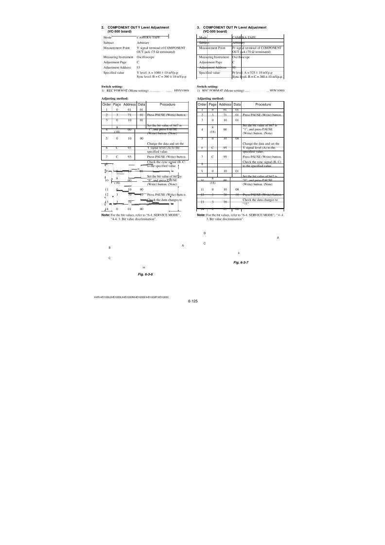
7/18/2019 SONY+HVR-HD1000 SERVICE MANUAL
http://slidepdf.com/reader/full/sonyhvr-hd1000-service-manual 263/4256-109HVR-HD1000J/HD1000U/HD1000N/HD1000E/HD1000P/HD1000C
4-3. Tape Path Adjustment
3-1. Adjustment Preparation1) Clean the tape running surface (tape guides, drum, capstan,
pinch roller) referring to Section “2-2. Tape Path System Clean-
ing”.
2) Connect the adjustment remote commander (Ref. No. J-1, J-
2) to the LANC terminal of the machine. Set the HOLD switch
to ON. (Set the slide switch to SERVICE)3) Connect an oscilloscope to CN8102 of the US-014 board via
the CPC-15 jig (J-6082-564-A) and the I/F unit for LANC
control jig (J-6082-521-A).Channel 1: US-014 board, CN8102 Pin1 (Note)
External trigger: US-014 board, CN8102 Pin2Note: Connect a 75 Ω resistor between pins 1 of CN8102
and3 (GND).
75 Ω resistor (Parts code: 1-247-804-11)
4) Play back the tracking standard (XH 2-1) (Ref. No. J-13).
5) Select page: 0, address: 10 and set data: 00.6) Select page: 3, address: 26 and set data: 31, and press the
PAUSE (Write) button.
7) Select page: 3, address: 33 and set data: 08.
8) Confirm that the RF waveform on the scope is flat at both of the entrance side and the exit side. (Refer to Fig. 6-2-7A.)
If the RF waveform is not flat either at the entrance side or the
exit side (refer to Fig. 6-2-7 B and C), perform the adjustmentof section “3-2. TG2/TG4 Guide Coarse Adjustment” and later.
9) Prepare an exclusive DVM-80 tape (commercial item).
(Remove the lid of the cassette.)
10) When the required conditions of step 8) are satisfied, perform
[Required Work upon Completion of Adjustment] as described
below upon completion of adjustment/check.
[Required Work upon Completion of Adjustment]
1) Connect the adjustment remote commander (Ref. No. J-1, J-
2) to the LANC terminal of the machine. Set the HOLD switch
to ON. (Set the slide switch to SERVICE)2) Select page: 0, address: 10 and set data: 00.
3) Select page: 3, address: 26 and set data: 00, and press the
PAUSE (Write) button.
4) Select page: 3, address: 33 and set data: 00.
Fig. 6-2-6
Fig. 6-2-7
Fig. 6-2-8
CH1
CH2 ( Trigger)
Envelope must be flat
3.3 msec
A Normal
B Entrance side is defective
C Exit side is defective
Entrance side Exit side
FWD
Tape
Tape must run while maintaining contact with the upper flange.There must not exist a large tape curl.
Drum
S reel T reel
TG6 guide TG5 guide TG4 guide
TG3 guide TG2 guide
TG1guide
Pinch roller
Capstan
Capstan
TG6 TG1TG5 TG4 TG3 TG2
There must not exist a large tape curl.
There must not exist a large tape curl.
Assemble without this part.
Cassette lid
Torsion spring
Exclusive DVM-80 tape(commercial item)
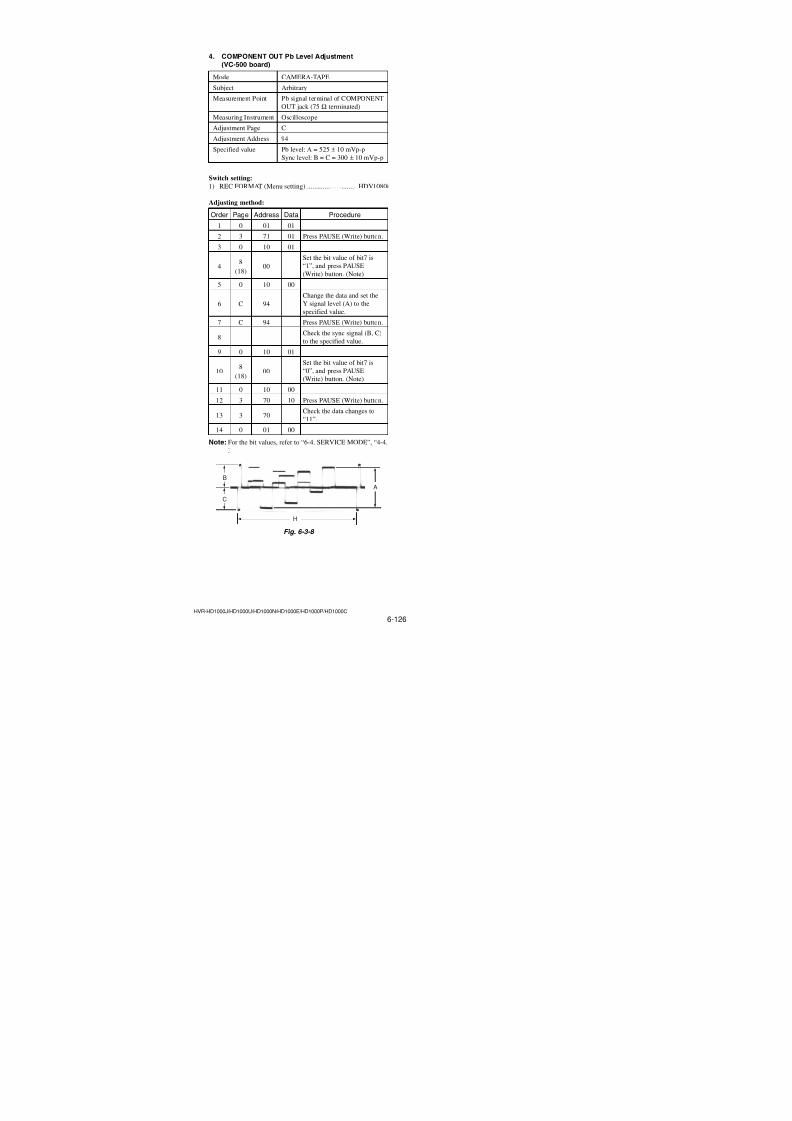
7/18/2019 SONY+HVR-HD1000 SERVICE MANUAL
http://slidepdf.com/reader/full/sonyhvr-hd1000-service-manual 264/4256-110HVR-HD1000J/HD1000U/HD1000N/HD1000E/HD1000P/HD1000C
3-2. TG2/TG4 Guide Coarse Adjustment1) Play back the tracking standard (XH 2-1) (Ref. No. J-13).
2) Adjust the TG2 and TG4 guides until the RF envelope wave-
form becomes flat. (Refer to Fig. 6-2-11.)
3-3. FWD Back Tension Adjustment1) Set the mini DV torque cassette (Ref. No. J-23) and establish
the FWD mode.
2) Confirm that the S side torque cassette reading value is in the
range as shown below.
0.29 to 0.39 mN•m (3.0 to 4.0 gf•cm)If the measurement value does not satisfy the specifications,
perform the following adjustment.
• If the measurement value is higher than the specification:
(Decreases the spring tension)
Move the tension coil spring hook to another spring stay in
the direction ofB.• If the measurement value is lower than the specification:
(Increases the spring tension)
Move the tension coil spring hook to another spring stay in
the direction ofA.
Fig. 6-2-9
Fig. 6-2-11
Fig. 6-2-12
Fig. 6-2-10
TG2 guide,Adjustment nut
TG4 guide,Adjustment nut
TG6 guide
TG5 guide
TG4 guide
TG3 guide
TG2 guide TG1 guide
Pinch roller
Drum
A
B
LS chassis ass'y
Tension regulator spring
Tenshion regulatorass'y (TG1 guide)
Entrance side Exit side
Entrance side Exit side
3-4. TG2/TG4 Guide Fine Adjustment1) Play back the tracking standard (XH 2-1) (Ref. No. J-13).
2) Adjust the TG2 so that the RF envelope has the larger ampli-
tude at the entrance side first, than adjust TG2 guide for flat
amplitude. (Refer to Fig. 6-2-11.)
3) Adjust the TG4 so that the RF envelope has the larger ampli-
tude at the exit side first, than adjust TG4 guide for flat ampli-tude. (Refer to Fig. 6-2-12.)
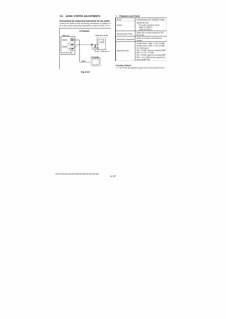
7/18/2019 SONY+HVR-HD1000 SERVICE MANUAL
http://slidepdf.com/reader/full/sonyhvr-hd1000-service-manual 265/4256-111HVR-HD1000J/HD1000U/HD1000N/HD1000E/HD1000P/HD1000C
3-5. TG1 Height Adjustment1) Replay the tracking standard (XH 2-1) (Ref. No. J-13).
2) Confirm that the waveform of the tape path is flat.
(Refer to Fig. 6-2-11, and 6-2-12.)3) Confirm to see that there are gaps between top edge of the
tape and the TG1 flange, and bottom edge and the TG1 flange.
(Refer to Fig. 6-2-13.)
If the top and/or the bottom edge of the tape contacts with
TG1 flange, adjust the height of the TG1 so that there is gapbetween the edge of the tape and the flange.
If the height of the TG1 is adjusted, check the entrance side of
the tape path waveform (refer to Fig. 6-2-11, and 6-2-12). If there is any change in the entrance side of the tape path wave-
form, re-adjust the entrance side (TG2). (Refer to “3-4. TG2/
TG4 Guide Fine Adjustment.)
Fig. 6-2-13
Clearance between tape and upper/lower flangesbecomes equality.
Measure the difference oftape run at this position
Tape
TG1 guide
TG1 guide
Drum
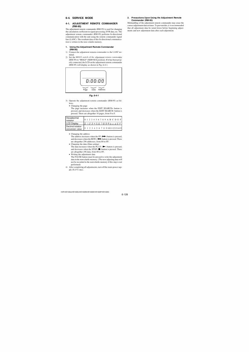
7/18/2019 SONY+HVR-HD1000 SERVICE MANUAL
http://slidepdf.com/reader/full/sonyhvr-hd1000-service-manual 266/4256-112HVR-HD1000J/HD1000U/HD1000N/HD1000E/HD1000P/HD1000C
Fig. 6-2-15
6) Repeat the steps from 2 to 5 until the tape height in the CUE
mode and REV mode becomes the same.
3-7. Tape Run Check 1) Play back the tracking standard (XH 2-1) (Ref. No. J-13). Es-
tablish the CUE mode first then the REV mode. Confirm in
the respective modes that there are no large tape curls at the
upper flange of TG2 and TG4. Then confirm in the respective
modes that there are no large tape curls at the upper and lowerflanges of TG1 and TG6.
3-6. TG6 Height AdjustmentNote: Perform “TG6 height adjustment” using the end segment of the tape
which is within the last 5 minutes from the end of the thin DVM-80
tape (commercial item).When using the DVM-80 (commercial item), use the modified one
by removing the cassette rid (Refer to Page 6-109. Adjustment
Preparation 9)).
1) Play back the tape (DVM-80) (commercial item).
2) Press the FF button to enter the CUE mode and measure the
tape height after 5 seconds have elapsed. (Fig. 6-2-14)3) Release your finger from the FF button and press the REW
button to enter the REV mode.
Measure the tape height after 3 seconds have elapsed.
4) Release your finger from the REW button.
5) Adjust the TG6 height so that the tape height in the CUE modeis the same as that in the REV mode.
Adjust the TG6 height by rotating the adjustment nut of the
TG6 guide in the following manner.
• Tape height in the REV mode is highert Rotate the ad-
justment nut clockwise
• Tape height in the REV mode is lowert Rotate the adjust-
ment nut counter-clockwise
Fig. 6-2-14
TG6 guide,Adjustment nut
Capstan motor
Drum
TG4 guide
TG5 guide
TG6 guide
Tape height in theREV mode is higher
Tape height in theREV mode is lower
Pinch roller Capstan motor shaft
Capstan motor shaft
Adjust so that theyhave the same height
FWD
Tape
Tape must run while maintaining contact with the upper flange.There must not exist a large tape curl.
Drum
S reel T reel
TG6 guide TG5 guide TG4 guide
TG3 guide TG2 guide
TG1guide
Pinch roller
Capstan
Capstan
TG6 TG1TG5 TG4 TG3 TG2
There must not exist a large tape curl.
There must not exist a large tape curl.
Ver. 1.1 2007.12
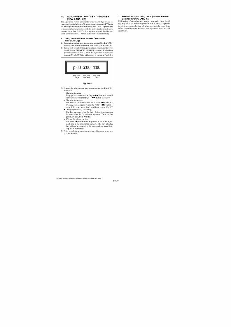
7/18/2019 SONY+HVR-HD1000 SERVICE MANUAL
http://slidepdf.com/reader/full/sonyhvr-hd1000-service-manual 267/4256-113HVR-HD1000J/HD1000U/HD1000N/HD1000E/HD1000P/HD1000C
3-8. Check upon Completion of Adjustment
1. Tracking Check 1) Play back the tracking standard (XH 2-1) (Ref. No. J-13).2) Establish the CUE (or REV) mode. Take the amplitude (A)
in this mode as the 100% waveform amplitude. (Refer to Fig.
6-2-16.)
3) Establish the FWD mode. Confirm that the difference between
the minimum (E min) and the maximum (E max) is less than30%. (When taking the amplitude (A) in the CUE or REV
mode as 100%)
4) Confirm that the RF waveform does not have excessive fluc-tuation of amplitude. (Fluctuation of amplitude should be 10%
or less at both entrance side (B) and exit side (C), when taking
the amplitude (A) in the CUE or REV mode as 100%)
Fig. 6-2-16
Fig. 6-2-17
Fig. 6-2-18
A=100%
E min E max
FWD mode
CUE/REV mode
E min: Minimum amplitude
E max: Maximum amplitude
(E max – E min) 30% or ( A)3
10
C 10% B 10%
FWD mode
B C A=100%
400 µsec
B = 50% or more
C = 50% or more
2. CUE/REV Check 1) Play back the tracking standard (XH 2-1) (Ref. No. J-13).
2) Establish the CUE mode. Confirm that the pitches between
the peaks of the RF waveform are equally spaced. Also con-firm that the RF waveform amplitude at entrance side (B) and
exit side (C) is 50% or more respectively, when taking the
amplitude (A) in the CUE or REV mode as 100%.
3) Establish the REV mode. Confirm that the pitches between
the peaks of the RF waveform are equally spaced. Also con-firm that the RF waveform amplitude at entrance side (B) and
exit side (C) is 50% or more respectively.
3. Rise-up Check 1) Play back the tracking standard (XH 2-1) (Ref. No. J-13).2) Change the modes from CUE mode to FWD. Confirm that the
RF waveform rises up within two seconds when the mode is
changed from CUE mode to FWD.
3) Change the modes from REV mode (two seconds or more of
REV and to the FWD within five seconds) to FWD. Confirm
that the RF waveform rises up within two seconds when the
mode is changed from REV mode to FWD.4) Change the modes from STOP mode to FWD. Confirm that
the RF waveform rises up within two seconds when the mode
is changed from STOP mode to FWD.
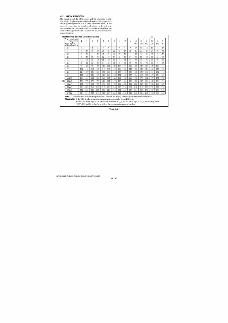
7/18/2019 SONY+HVR-HD1000 SERVICE MANUAL
http://slidepdf.com/reader/full/sonyhvr-hd1000-service-manual 268/4256-114HVR-HD1000J/HD1000U/HD1000N/HD1000E/HD1000P/HD1000C
3-1-2. Adjusting ConnectorsThe measuring point of the playback RF signal is CN8102 of US-014 board. Connect the measuring instruments via the CPC con-
necting jigs (J-6082-521-A, J-6082-564-A). Refer to “MECHA-
NISM SECTION ADJUSTMENT” for the measuring method. The
following table lists the pin numbers and signal names of CN8102.
Pin No. Signal Name1 RF_MON
2 SWP
3 GND
4 N. C.
5 N. C.
6 N. C.
7 N. C.
8 GND
Table 6-3-1
3-1-3. Connecting the EquipmentConnect the measuring instruments as shown in Fig. 6-3-1, and
perform the adjustments.
Fig. 6-3-1
6-3. VIDEO SECTION ADJUSTMENTS
3-1. PREPARATIONS BEFORE ADJUSTMENTSUse the following measuring instruments for video section adjust-ments.
3-1-1. Precautions on AdjustingNote: Before performing the adjustment, check the data of page:
0, address: 10 is “00”. If not, select page: 0, address: 00,
and set data “00”.
1) The adjustments of this unit are performed in the VTR mode
(PLAY/EDIT mode) or camera mode (CAMERA-TAPE
mode).
Video (Yellow)
S Video
(Black)
Pr (Red)
Pb (Blue)
Y (Green)
VIDEO system adjustment (COMPONENT OUT)
VIDEO system adjustment (S VIDEO, VIDEO)
AC IN
Adjustment remote
DC IN jack
LANC jack
commander
(RM-95)
(NEW LANC JIG)
US-014 board
CN8102
Terminated75 Ω
Terminated75 Ω
Osilloscope
Osilloscope
AC adaptorAC-L100(1-479-286-21)
RM-95(J-6082-053-B)
NEW LANC JIG(J-6082-565-A)LANC cable(J-6082-442-A)
For tape path adjustment
8 8
1
1 RF MON
SWP
GND
CPC-15 (J-6082-564-A)
CN002
CN001
BATT
LANC Not used
Not used
Not used
*1
*1 I/F unit for LANC control (J-6082-521-A)
*1: Don't connect any cable to these connectors.
1
32
13
23
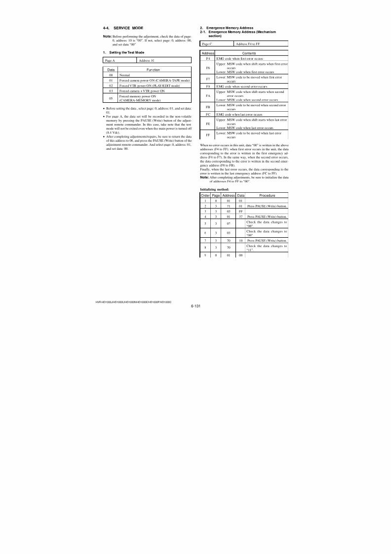
7/18/2019 SONY+HVR-HD1000 SERVICE MANUAL
http://slidepdf.com/reader/full/sonyhvr-hd1000-service-manual 269/4256-115HVR-HD1000J/HD1000U/HD1000N/HD1000E/HD1000P/HD1000C
3-1-4. Alignment TapesUse the alignment tapes shown in the following table.Use tapes specified in the signal column of each adjustment.
Name Use
Tracking standard (XH2-1) Tape path adjustment
SW/OL standard (XH2-3)Switching position adjust-
ment
Audio operation check Audio system adjustment
(XH5-3(NTSC), XH5-3P(PAL))
System operation check Operation check
(XH5-5(NTSC), XH5-5P(PAL))
Fig. 6-3-2 shows the 75% color bar signals recorded on the align-
ment tape for Audio Operation Check.
Note: Measure with video terminal (Terminated at 75 Ω)
Fig. 6-3-2 Color bar signal of alignment tapes
For NTSC model
For PAL model
Color bar signal waveform Color bar pattern
Color bar signal waveform Color bar pattern
3-1-5. Output Level and ImpedanceVIDEO OUT jack
Pin jack, 1 Vp-p, 75 Ω (ohms)
S VIDEO OUT jack
4-pin mini DIN
Luminance signal:
1 Vp-p, 75 Ω (ohms)
Chrominance signal:
0.286 Vp-p, 75 Ω (ohms) (NTSC)0.300 Vp-p, 75 Ω (ohms) (PAL)
1 V
0.714 V
0.286 V
White (75%)
White (100%)
Y e l l o w
C y a n
G r e e n
M a g e n t a
R e d
B l u e Burst signal
0.286 V
Q I
Horizontal sync signal
(75%) W
h i t e
Y e l l o w
C y a n
G r e e n
M a g e n t a
R e d
B l u e
Q I
White(100%)
Black
1 V0.7 V
0.3 V
White (100%)
Y e l l o w
C y a n
G r e e n
M a g e n t a
R e d
B l u e
Burst signal
Horizontal sync signal
0.3 V
(100%)
Y e l l o w
C y a n
G r e e n
M a g e n t a
R e d
B l u e
W h i t e
B l a c k
AUDIO OUT jack
Pin jack
Audio signal: 327 mV (at load impedance 47 k Ω (kilohms)),
Output impedance with less than 2.2 k Ω (kilohms)
COMPONENT OUT jack
Y: 1 Vp-p, 75 Ω (ohms)
PB /PR, CB /CR: ± 350 mV, 75 Ω (ohms)
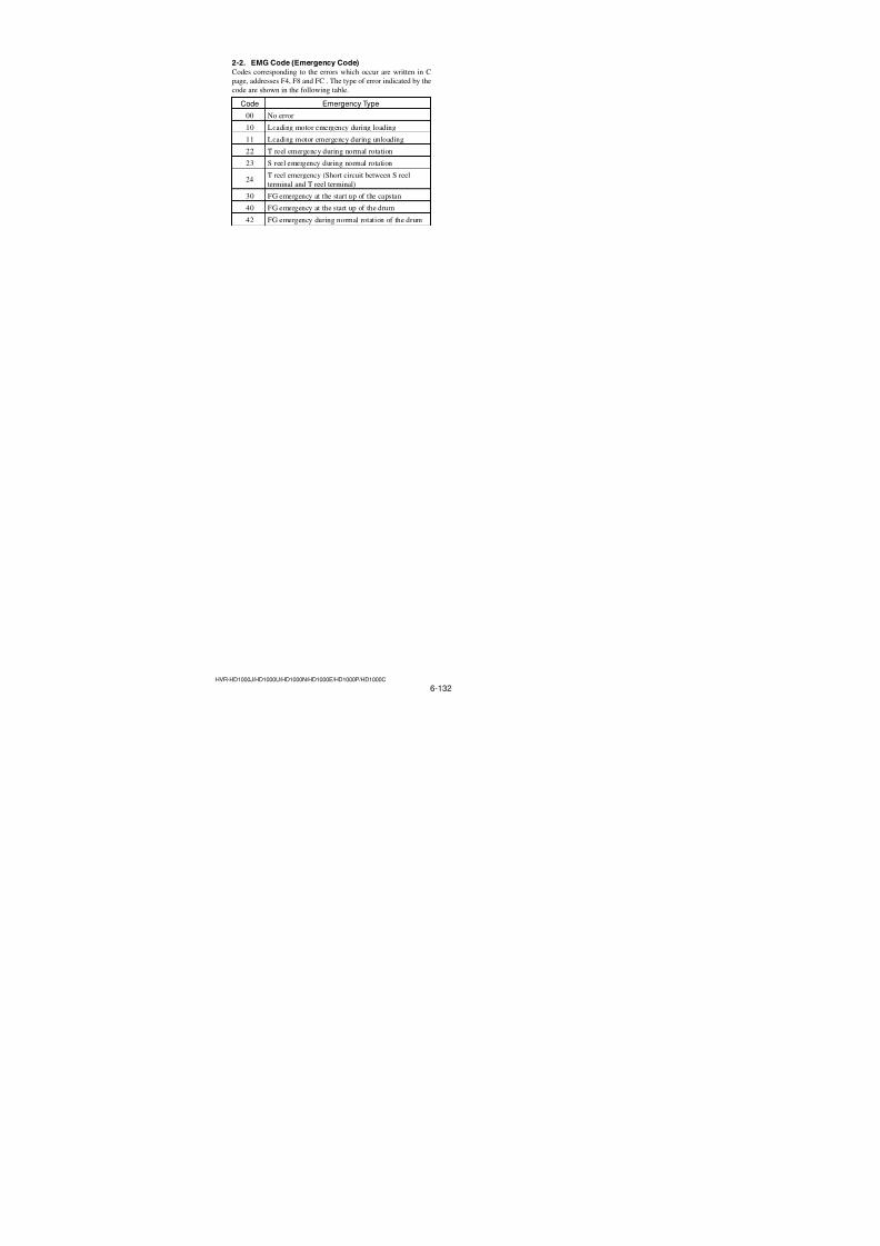
7/18/2019 SONY+HVR-HD1000 SERVICE MANUAL
http://slidepdf.com/reader/full/sonyhvr-hd1000-service-manual 270/4256-116HVR-HD1000J/HD1000U/HD1000N/HD1000E/HD1000P/HD1000C
D1 (decimal) D2 (decimal) H1 (hexadecimal)
(Service model code)
00001 to 65535 D1 FE
65536 to 131071 D1 − 65536 FE
131072 to196607 D1 − 131072 FE
196608 to 262143 D1 − 196608 FE262144 to 327679 D1
− 262144 FE
327680 to 393215 D1 − 327680 FE
393216 to 458751 D1 − 393216 FE
458752 to 524287 D1 − 458752 FE
524288 to 589823 D1 − 524288 FE
589824 to 655359 D1 − 589824 FE
655360 to 720895 D1 − 655360 FE
720896 to 786431 D1 − 720896 FE
786432 to 851967 D1 − 786432 FE
851968 to 917503 D1 − 851968 FE
917504 to 983039 D1 − 917504 FE
983040 to 999999 D1 − 983040 FE
Table 6-3-2
5) Enter H1 to address: 09 on page: 13.
Example: If H1 = FE,
Select page: 0, address: 10, and set data: 01.
Select page: 3 (13), address: 09, and set data: FE, then press
the PAUSE (Write) button.
6) From Table 6-3-3, obtain the maximum decimal number lessthan D2, and it is assumed to be D3.
Example: If D2 = 12345.
D3
= 122887) From Table 6-3-3, obtain a hexadecimal number that corre-
sponds to D3, and it is assumed to be H3.
Example: If D3 = 12288,
H3 = 30008) Caluculate D4 using following equations (decimal
caluculation). (0 D4
225)
D4 = D2 – D3
Example: If D2 = 12345 and D3 = 12288,
D4 = 12345 – 12288 = 57
9) Convert D4 into a hexadecimal number to obtain H4. (See Table
6-4-1 “Hexadecimal - decimal conversion table” in 6-4. Ser-vice Mode)
Example: If D4 = 57,
H4 = 3910) Enter higher two digits of H3 to address: 0A on page: 13.
Example: If H3 = 3000,
Select page: 0, address: 10, and set data: 01.
Select page: 3 (13), address: 0A, and set data: 30, then press
the PAUSE (Write) button.11) Enter H4 to address: 0B on page: 13.
Example: If H4 = 39,
Select page: 0, address: 10, and set data: 01.
Select page: 3 (13), address: 0B, and set data: 39, then press
the PAUSE (Write) button.
12) Select page: 0, address: 10, and set data: 00.
13) Select page: 3, address: 70, and set data: 10, then press thePAUSE (Write) button.
14) Select page: 3, address: 70, and check that the data changes to“11”.
15) Select page: 0, address: 01, and set data: 00.
3-2. SYSTEM CONTROL SYSTEM ADJUSTMENTS
1. Initialization of EEPROM DataIf the EEPROM data is erased due to some reason, perform “1-2.
INITIALIZATION OF EEPROM DATA”, of “6-1. CAMERA
SECTION ADJUSTMENTS”
2. Node Unique ID No. InputNote 1: Perform “2-2. Input of Serial No.” if the data on page 13
has been cleared and original node unique ID No. is un-certain.
Usually, read the data on page 13 before repair, and write
it after repair.
Note 2: If reading/writing data on pages 13, set data: 01 to page:
0, address: 10, and then select pages: 3. By this data set-
ting, the pages 13 can be selected.
After the data reading/writing finished, return the dataon page: 0, address: 10 to “00”.
2-1. Input of Company ID
Write the company ID to the EEPROM (nonvolatile memory).Page 13
Address 04, 05, 06, 07, 08
Input method:
1) Select page: 0, address: 01, and set data: 01.2) Select page: 3, address: 71, and set data: 01, then press the
PAUSE (Write) button.
3) Select page: 0, address: 10, and set data: 01.
4) Select page: 3 (13), and enter the following data.
Note 3: Each time the data is set, press the PAUSE (Write) but-
ton on the adjusting remote commander.
Address Data
04 08
05 00
06 46
07 01
08 02
5) Select page: 0, address: 10, and set data: 00.6) Select page: 3, address: 70, and set data: 10, then press the
PAUSE (Write) button.
7) Select page: 3, address: 70, and check that the data changes to
“11”.
8) Select page: 0, address: 01, and set data: 00.
2-2. Input of Serial No.Write the serial No. and model code to the EEPROM (nonvolatile
memory).
In writing the serial No., a decimal number should be converted
into a hexadecimal number
Page 13
Address 09, 0A, 0B
1) Select page: 0, address: 01, and set data: 01.2) Select page: 3, address: 71, and set data: 01, then press the
PAUSE (Write) button.
3) Read the serial No. from the model name label, and it is as-
sumed to be D1.
Example: If serial No. is “77881”,D1 = 77881
4) From Table 6-3-2, obtain D2 and H1 that correspond to D1.Example: If D1 = 77881,
D2 = D1 – 65536 = 12345
H1 = FE
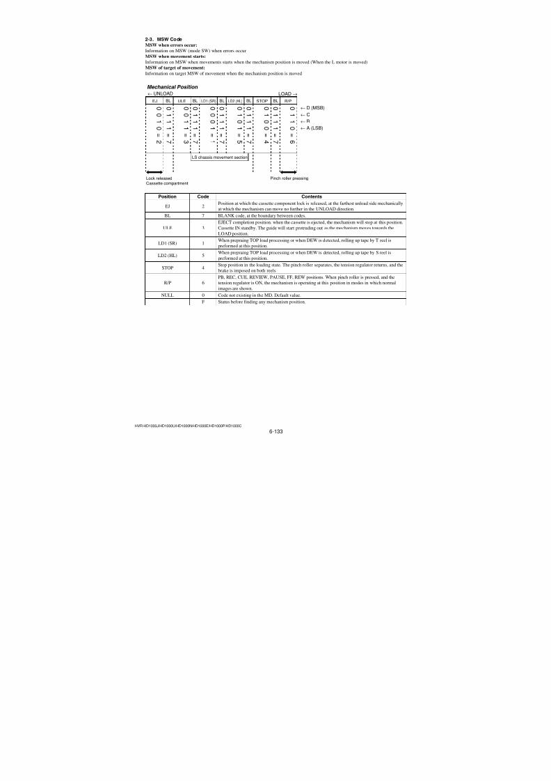
7/18/2019 SONY+HVR-HD1000 SERVICE MANUAL
http://slidepdf.com/reader/full/sonyhvr-hd1000-service-manual 271/4256-117HVR-HD1000J/HD1000U/HD1000N/HD1000E/HD1000P/HD1000C
D3 H3 D3 H3 D3
0 0000 8192 2000 16384 4000 24576 6000 32768 8000 40960 A000 49152 C000 57344 E000
256 0100 8448 2100 16640 4100 24832 6100 33024 8100 41216 A100 49408 C100 57600 E100
512 0200 8704 2200 16896 4200 25088 6200 33280 8200 41472 A200 49664 C200 57856 E200
768 0300 8960 2300 17152 4300 25344 6300 33536 8300 41728 A300 49920 C300 58112 E300
1024 0400 9216 2400 17408 4400 25600 6400 33792 8400 41984 A400 50176 C400 58368 E4001280 0500 9472 2500 17664 4500 25856 6500 34048 8500 42240 A500 50432 C500 58624 E500
1536 0600 9728 2600 17920 4600 26112 6600 34304 8600 42496 A600 50688 C600 58880 E600
1792 0700 9984 2700 18176 4700 26368 6700 34560 8700 42752 A700 50944 C700 59136 E700
2048 0800 10240 2800 18432 4800 26624 6800 34816 8800 43008 A800 51200 C800 59392 E800
2304 0900 10496 2900 18688 4900 26880 6900 35072 8900 43264 A900 51456 C900 59648 E900
2560 0A00 10752 2A00 18944 4A00 27136 6A00 35328 8A00 43520 AA00 51712 CA00 59904 EA00
2816 0B00 11008 2B00 19200 4B00 27392 6B00 35584 8B00 43776 AB00 51968 CB00 60160 EB00
3072 0C00 11264 2C00 19456 4C00 27648 6C00 35840 8C00 44032 AC00 52224 CC00 60416 EC00
3328 0D00 11520 2D00 19712 4D00 27904 6D00 36096 8D00 44288 AD00 52480 CD00 60672 ED00
3584 0E00 11776 2E00 19968 4E00 28160 6E00 36352 8E00 44544 AE00 52736 CE00 60928 EE00
3840 0F00 12032 2F00 20224 4F00 28416 6F00 36608 8F00 44800 AF00 52992 CF00 61184 EF004096 1000 12288 3000 20480 5000 28672 7000 36864 9000 45056 B000 53248 D000 61440 F000
4352 1100 12544 3100 20736 5100 28928 7100 37120 9100 45312 B100 53504 D100 61696 F100
4608 1200 12800 3200 20992 5200 29184 7200 37376 9200 45568 B200 53760 D200 61952 F200
4864 1300 13056 3300 21248 5300 29440 7300 37632 9300 45824 B300 54016 D300 62208 F300
5120 1400 13312 3400 21504 5400 29696 7400 37888 9400 46080 B400 54272 D400 62464 F400
5376 1500 13568 3500 21760 5500 29952 7500 38144 9500 46336 B500 54528 D500 62720 F500
5632 1600 13824 3600 22016 5600 30208 7600 38400 9600 46592 B600 54784 D600 62976 F600
5888 1700 14080 3700 22272 5700 30464 7700 38656 9700 46848 B700 55040 D700 63232 F700
6144 1800 14336 3800 22528 5800 30720 7800 38912 9800 47104 B800 55296 D800 63488 F800
6400 1900 14592 3900 22784 5900 30976 7900 39168 9900 47360 B900 55552 D900 63744 F900
6656 1A00 14848 3A00 23040 5A00 31232 7A00 39424 9A00 47616 BA00 55808 DA00 64000 FA006912 1B00 15104 3B00 23296 5B00 31488 7B00 39680 9B00 47872 BB00 56064 DB00 64256 FB00
7168 1C00 15360 3C00 23552 5C00 31744 7C00 39936 9C00 48128 BC00 56320 DC00 64512 FC00
7424 1D00 15616 3D00 23808 5D00 32000 7D00 40192 9D00 48384 BD00 56576 DD00 64768 FD00
7680 1E00 15872 3E00 24064 5E00 32256 7E00 40448 9E00 48640 BE00 56832 DE00 65024 FE00
7936 1F00 16128 3F00 24320 5F00 32512 7F00 40704 9F00 48896 BF00 57088 DF00 65280 FF00
H3 D3 H3 D3 H3 D3 H3 D3 H3 D3 H3
Note: D3: Decimal
H3: Hexadecimal
Table 6-3-3
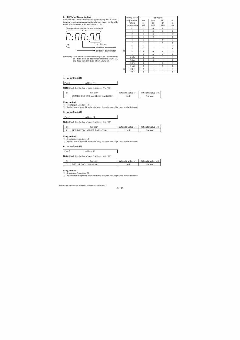
7/18/2019 SONY+HVR-HD1000 SERVICE MANUAL
http://slidepdf.com/reader/full/sonyhvr-hd1000-service-manual 272/4256-118HVR-HD1000J/HD1000U/HD1000N/HD1000E/HD1000P/HD1000C
Input method:
1) Select page: 0, address: 01, and set data: 01.2) Select page: 3, address: 71, set data: 01, and press the PAUSE
(Write) button.
3) Select page: B, and enter the following data.
Note 5: Each time the data is set, press the PAUSE (Write) but-
ton on the adjusting remote commander.
Address Data
D6 First and first 2nd digits of serial number
D7 First 3rd and 4th digits of serial number
D8 First 5th and 6th digits of serial number
D9 First 7th and 8th digits of serial number
Note 6: If the serial number is less than 8 digits, set “0” at the top
of serial number by the amount of shortage of digits.
Example: If the serial number is “1234567”, set “01234567”.
D6 = 01
D7 = 23
D8 = 45D9 = 67
4) Select page: 3, address: 70, set data: 10, and press the PAUSE
(Write) button.
5) Select page: 3, address: 70, and check that the data is “11”.
6) Select page: 0, address: 01, and set data: 00.
Charactor ! " # $ % & ' ( )
ASCII Code 20 21 22 23 24 25 26 27 28 29
Charactor * + , - . /
ASCII Code 2a 2b 2c 2d 2e 2f
Charactor 0 1 2 3 4 5 6 7 8 9
ASCII Code 30 31 32 33 34 35 36 37 38 39
Charactor : ; < = > ?
ASCII Code 3a 3b 3c 3d 3e 3f
Charactor @ A B C D E F G H I
ASCII Code 40 41 42 43 44 45 46 47 48 49
Charactor J K L M N O
ASCII Code 4a 4b 4c 4d 4e 4f
Charactor P Q R S T U V W X Y
ASCII Code 50 51 52 53 54 55 56 57 58 59
Charactor Z [ ¥ ] ^ _
ASCII Code 5a 5b 5c 5d 5e 5f Charactor ` a b c d e f g h i
ASCII Code 60 61 62 63 64 65 66 67 68 69
Charactor j k l m n o
ASCII Code 6a 6b 6c 6d 6e 6f
Charactor p q r s t u v w x y
ASCII Code 70 71 72 73 74 75 76 77 78 79
Charactor z | ~
ASCII Code 7a 7b 7c 7d 7e
3. USB Serial Number Data SettingSet the serial number data of the USB.
Note 1: Before the repair, read the data of the set to be repaired,
and write the read data after the repair.
Perform “3-1. Model Number Input” and “3-2. Serial
Number Input”, if the data on page B is erased and origi-
nal USB serial number is unknown.Note 2: Check that the data of page: 0, address: 10 is “00”.
3-1. Model Number InputWrite the model number to the EEPROM (nonvolatile memory).
For the model number, enter the ASCII codes that correspond to
the last 5 characters of the model name given on the model name
label of the set.
Page B
Address D1, D2, D3, D4, D5
Input method:
1) Select page: 0, address: 01, and set data: 01.2) Select page: 3, address: 71, set data: 01, and press the PAUSE
(Write) button.
3) Select page: B, and enter the following data.Note 3: Each time the data is set, press the PAUSE (Write) but-
ton on the adjusting remote commander.
Address Data
D1 Last 5th character on model name label (Note 4)
D2 Last 4th character on model name label
D3 Last 3rd character on model name label
D4 Last 2nd character on model name label
D5 Last character on model name label
Note 4: If the model name is less than 5 characters, justify the
codes to the right and set “20” for the remainder.
Example: If the model name is “HVR-HD1000U”, set “3130303055”.
D1 = 31D2 = 30
D3 = 30
D4 = 30
D5 = 55
4) Select page: 3, address: 70, set data: 10, and press the PAUSE
(Write) button.5) Select page: 3, address: 70, and check that the data is “11”.
6) Select page: 0, address: 01, and set data: 00.
3-2. Serial Number InputWrite the serial number to the EEPROM (nonvolatile memory).
For the serial number, set the serial number given on the model
name label of the set.
Page B
Address D6, D7, D8, D9
Table 6-3-4
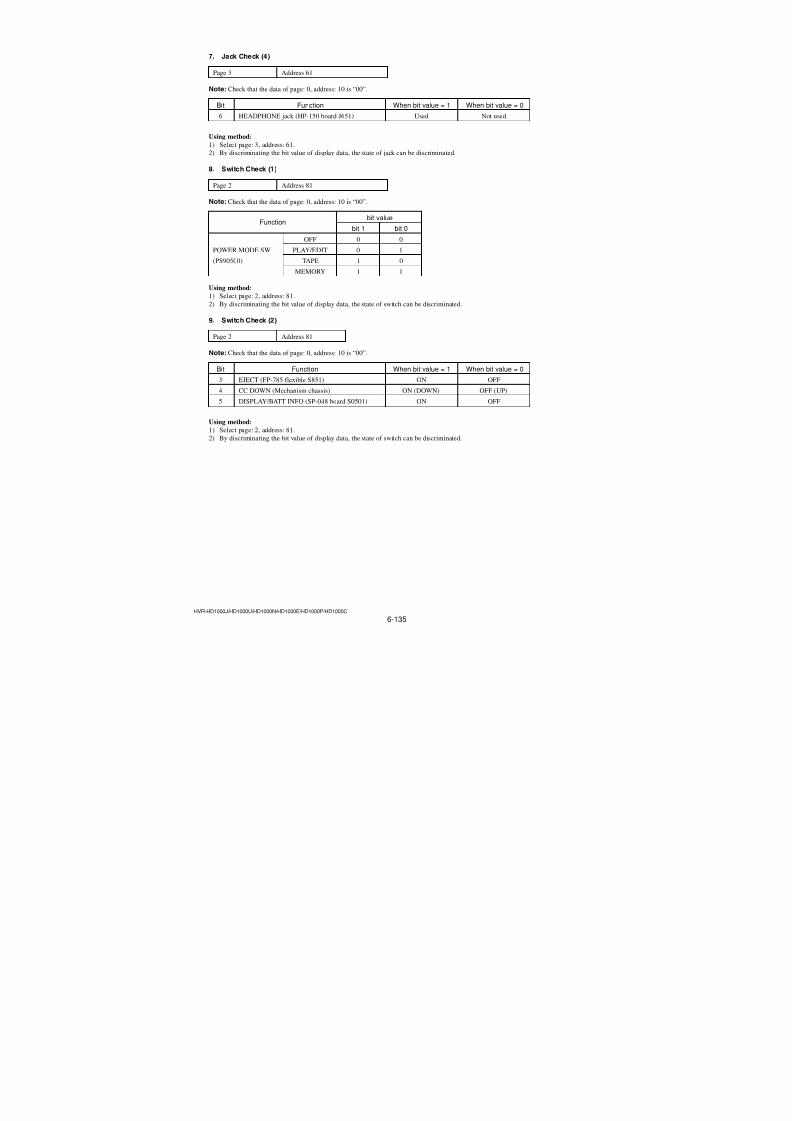
7/18/2019 SONY+HVR-HD1000 SERVICE MANUAL
http://slidepdf.com/reader/full/sonyhvr-hd1000-service-manual 273/4256-119HVR-HD1000J/HD1000U/HD1000N/HD1000E/HD1000P/HD1000C
1. CAP FG Duty Adjustment (VC-500 board)
adaradarRadarW
Set the CAP FG signal duty cycle to 50% to establish an appropri-
ate capstan servo. If deviated, the uneven rotation of capstan and
noise can occur.
Mode VTR stop (PLAY/EDIT mode)
Signal No signal
Measurement Point Displayed data of page: 3, address:
03
Measuring Instrument Adjusting remote commander
Adjustment Page C
Adjustment Address 16
Specified value The data of page: 3, address: 03 is
“00”
Note 1: Check that the data of page: 0, address: 10 is “00”.
Adjusting method:
Order Page Address Data Procedure
1
Close the cassette compart-
ment without inserting
cassette.
2 0 01 01
3 3 03 FF
4 3 71 01 Press PAUSE (Write) button.
5 3 01 1B Press PAUSE (Write) button.
6 3 02
Check the data changes in
the following order
“1B”t “2B”t “00”
7 3 03 Check the data is “00”. (Note 2)8 3 01 00 Press PAUSE (Write) button.
9 3 70 10 Press PAUSE (Write) button.
10 3 70 Check the data changes to
“11”.
11 0 01 00
Note 2: If the data is “01”, adjustment has errors or the mecha-
nism deck is defective.
If the data is “80”, the mechanism deck is in emergency
state or the end of tape was detected.
3-3. SERVO AND RF SYSTEM ADJUSTMENTSBefore perform the servo and RF system adjustments, check that
the specified values of “Origin Oscillation check” of “1-3. CAM-ERA SYSTEM ADJUSTMENTS” is satisfied.
Check that the data of page: 0, address: 10 is “00”. If not, select
page: 0, address: 10, and set the data “00”.
Adjusting Procedure:
1. CAP FG duty adjustment
2. Switching position adjustment3. Error rate check
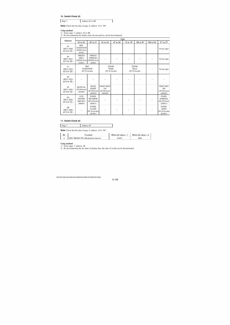
7/18/2019 SONY+HVR-HD1000 SERVICE MANUAL
http://slidepdf.com/reader/full/sonyhvr-hd1000-service-manual 274/4256-120HVR-HD1000J/HD1000U/HD1000N/HD1000E/HD1000P/HD1000C
Note 3: If bit0 of the data is “1”, the EVEN channel is defective.
If bit1 of the data is “1”, the ODD channel is defective.Contents of the defect is see written into page: C, ad-
dress: 10 and 12. See following table.
(For the bit values, refer to “6-4. SERVICE MODE”,
“4-4. 3. Bit value discrimination”.)
If bit3 of the data is “1”, the tape end being played, so
rewind the tape and perform the adjustment again.
When the EVEN channel is defective
Data of page: C, Contents of defectaddress: 10
EE Writing into Flash is defective
E8 Adjustment data is out of range
E7 No data is returned from IC2701
When the ODD channel is defective
Data of page: C, Contents of defectaddress: 12EE Writing into Flash is defective
E8 Adjustment data is out of range
E7 No data is returned from IC2701
2. Switching Position Adjustment (VC-500 board)
RadarW adarRadarW adarRadarW
Mode VTR playback (PLAY/EDIT mode)
Signal SW/OL standard (XH2-3)
Measurement Point Displayed data of page: 3, address:
03Measuring Instrument Adjusting remote commander
Adjustment Page C
Adjustment Address 10, 11, 12, 13
Specified value The data of page: 3, address: 03 is
“00”
Note 1: Check that the data of page: 0, address: 10 is “00”.
Adjusting method:
Order Page Address Data Procedure
1
Insert the SW/OL standard
tape and enter the VTR stopmode.
2 0 01 01
3 3 71 01 Press PAUSE (Write) button.
4 C 10 EE Press PAUSE (Write) button.
5 3 03 FF
6 3 21 Check the data is “02”. (Note 2)
7 3 01 0D Press PAUSE (Write) button.
8 3 02 Check the data changes to “00”.
9 3 03 Check the data is “00”. (Note 3)
10 3 01 00 Press PAUSE (Write) button.
11 3 70 10 Press PAUSE (Write) button.
12 3 70 Check the data changes to
“11”.
13 0 01 00
Note 2: If the data is “72”, the tape top being played. After play-
ing the tape for 1 to 2 seconds, stop it, perform step 5 and
higher.
If the data is “62”, the tape end being played. After re-
wind the tape, perform step 5 and higher.
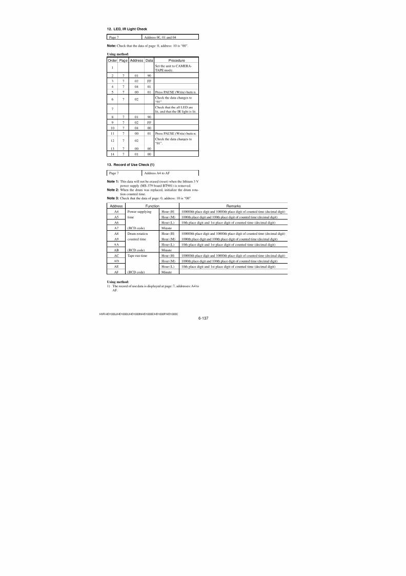
7/18/2019 SONY+HVR-HD1000 SERVICE MANUAL
http://slidepdf.com/reader/full/sonyhvr-hd1000-service-manual 275/4256-121HVR-HD1000J/HD1000U/HD1000N/HD1000E/HD1000P/HD1000C
3. Error Rate Check (VC-500 board) RadarW adarRadarW adarRadarW
Note: Check that the data of page: 0, address: 10 is “00”.
3-1. Preparations before adjustments
Mode Camera recording (CAMERA-TAPE mode)
Subject Arbitrary
Switch setting
1) REC FORMAT (Menu setting) .........................................DV
Adjusting method:
Order Page Address Data Procedure
1 0 01 01
2 3 71 01 Press PAUSE (Write) button.
3 0 10 01
4C
0D C8 Press PAUSE (Write) button.(1C)
5 0 10 00
6 Record the camera signal for
2 minutes.
3-2. Error Rate Check
Mode VTR playback (PLAY/EDIT mode)
Subject Recorded signal at “Preparations
before adjustments”
Measurement Point Displayed data of page: 3, address:
03
Measuring Instrument Adjusting remote commander
Adjustment Page CAdjustment Address B2 to C7
Specified value The data of page: 3, address: 03 is
“00”
Note 1: Check that the data of page: 0, address: 10 is “00”.
Initial Value of Page C: Address: B2 to C7
Address Initial Address Initial Address Initialvalue value value
B2 00 BA 00 C2 80
B3 00 BB 00 C3 00
B4 00 BC 00 C4 00B5 00 BD 00 C5 00
B6 00 BE 00 C6 00
B7 80 BF 00 C7 00
B8 00 C0 00
B9 00 C1 00
Table 6-3-5
Adjusting method:
Order Page Address Data Procedure
1 0 01 01
2 3 71 01 Press PAUSE (Write) button.
3
Check that the data of page:
C, address: B2 to C7 is theinitial value. (See Table 6-3-
5)
4
Playback the recorded signal
at “Preparations before
adjustments”.
5 3 03 FF
6 3 01 40 Press PAUSE (Write) button.
7 3 02Check the data changes to
“00”.
8 3 03 Check the data is “00”. (Note 2)
9 3 01 00 Press PAUSE (Write) button.
10 Perform “Processing afterCompleting Adjustments”.
Note 2: If the data is other than “00”, Error rate is abnormal.
For the contents of the abnormality, see the following
table.
Data of page: 3, Contents of defectaddress: 03
01 EVEN channel is abnormal.
02 ODD channel is abnormal.
03 EVEN channel and ODD channel areabnormal.
Note 3: If Error rate is abnormal, Check the use tape, clean thetape running surface. And after inputting initial values to
page C: address: B2 to C7, perform re-adjustment. (See
Table 6-3-5)
Processing after Completing Adjustment:
Order Page Address Data Procedure
1 0 01 01
2 0 10 01
3 C 0D 00 Press PAUSE (Write) button.(1C)
4 0 10 00
5 3 70 10 Press PAUSE (Write) button.
6 3 70 Check the data changes to
“11”.
7 0 01 00
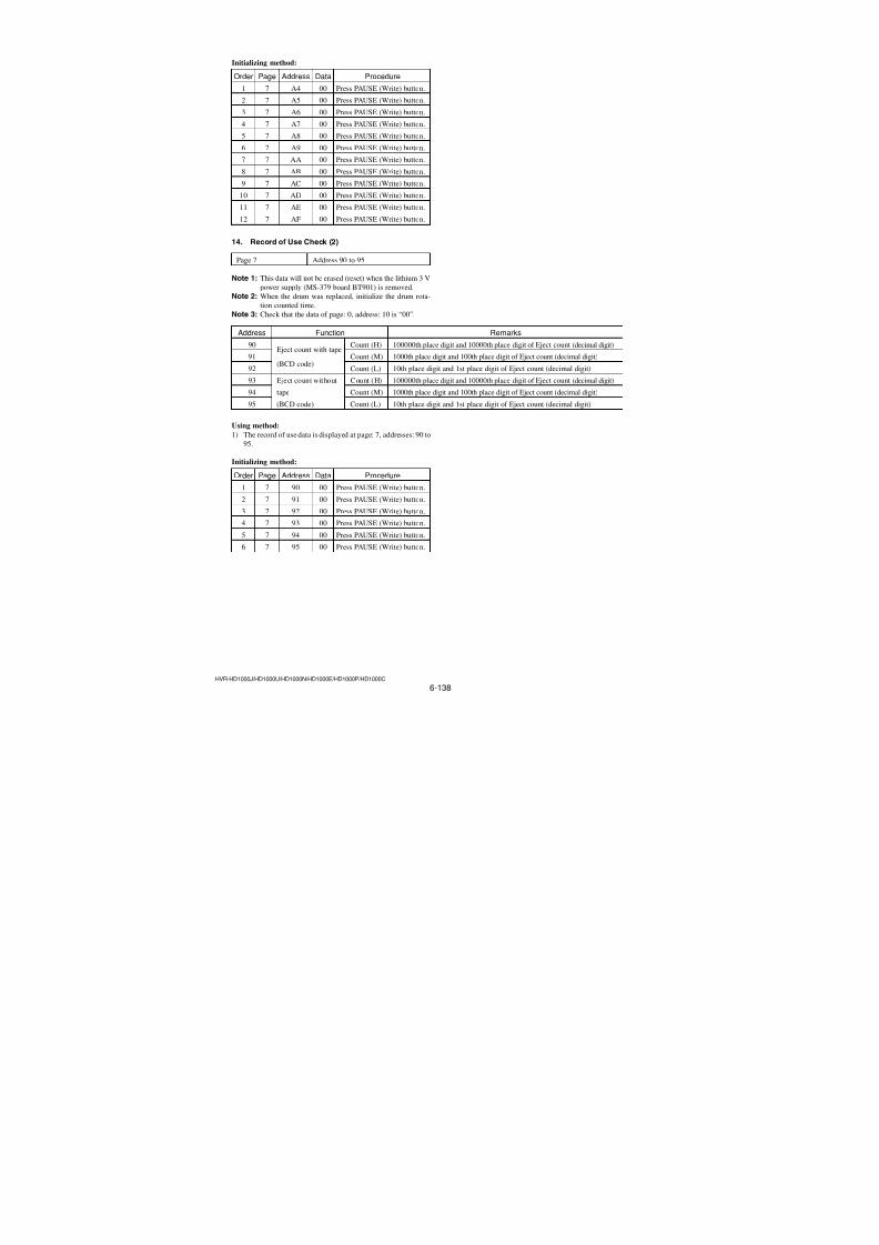
7/18/2019 SONY+HVR-HD1000 SERVICE MANUAL
http://slidepdf.com/reader/full/sonyhvr-hd1000-service-manual 276/4256-122HVR-HD1000J/HD1000U/HD1000N/HD1000E/HD1000P/HD1000C
1-2. S VIDEO OUT Y Level Adjustment (VC-500 board)
Mode PLAY/EDIT
Signal No signal
Measurement Point Y signal terminal of S VIDEO plug
of A/V OUT jack (75 Ω terminated)
Measuring Instrument OscilloscopeAdjustment Page C
Adjustment Address 25 (NTSC)
85 (PAL)
Specified value A = 1000 ± 14 mVp-p
Adjusting method:
Order Page Address Data Procedure
1 Perform “Preparations”.
2 C
Change the data and set the Y
signal level (A) to the
specified value.
3 C Press PAUSE (Write) button.
4Perform “Processing after
Complete Adjustment”.
Fig. 6-3-3
3-4. VIDEO SYSTEM ADJUSTMENTSBefore perform the video system adjustments, check that the speci-
fied values of “Origin Oscillation Check” of “1-3. CAMERA SYS-TEM ADJUSTMENTS” is satisfied.
Check that the data of page: 0, address: 10 is “00”.
If not, select page: 0, address: 10, and set the data “00”.
Adjusting Procedure:
1. S VIDEO OUT Y level adjustment
2. S VIDEO OUT chroma level adjustment3. VIDEO OUT level check
4. COMPONENT OUT Y level adjustment
5. COMPONENT OUT Pr level adjustment
6. COMPONENT OUT Pb level adjustment
1. S VIDEO, VIDEO OUT Adjustment1-1. PreparationsPerform the following data setting before the “S VIDEO, VIDEO
OUT Adjustment”.
Order Page Address Data Procedure
1 Set the unit to PLAY/EDIT
mode.
2 0 01 01
3 3 71 01 Press PAUSE (Write) button.
4 0 10 01
58
00 01 Press PAUSE (Write) button.(18)
6 8 01 60 Press PAUSE (Write) button.(18)
7 C 0F 10 Press PAUSE (Write) button.(1C)
8 8 06 55 Press PAUSE (Write) button.(18)
9 8 04 C0 Press PAUSE (Write) button.(18)
10 0 10 00
11 Wait for 5 sec.
12 0 FF 3E
13 B 00 02
14 C 85 Check the data is “55”.
15 B 00 00
16 0 FF 00
H
A
(NTSC)
25
(PAL)85
(NTSC)25
(PAL)
85
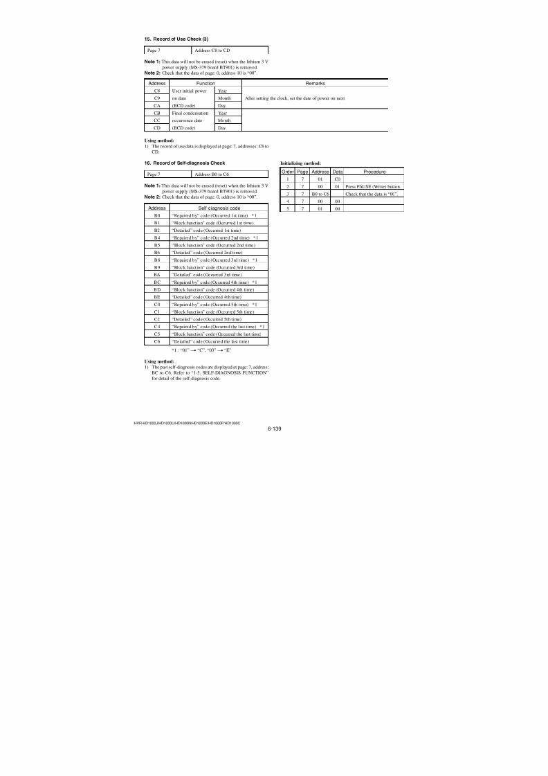
7/18/2019 SONY+HVR-HD1000 SERVICE MANUAL
http://slidepdf.com/reader/full/sonyhvr-hd1000-service-manual 277/4256-123HVR-HD1000J/HD1000U/HD1000N/HD1000E/HD1000P/HD1000C
1-3. S VIDEO OUT Chroma Level Adjustment(VC-500 board)
Mode PLAY/EDIT
Signal No signal
Measurement Point Chroma signal terminal of S VIDEO
plug of A/V OUT jack
(75 Ω terminated)External trigger: Y signal terminal of
S VIDEO plug of A/V OUT jack
(75 Ω terminated)
Measuring Instrument Oscilloscope
Adjustment Page C
Adjustment Address 26, 27 (NTSC)
86, 87 (PAL)
Specified value Cr level: A = 714 ± 14 mVp-p(NTSC)
A = 700 ± 14 mVp-p(PAL)
Cb level: B = 714 ± 14 mVp-p(NTSC)
B = 700 ± 14 mVp-p(PAL)
Burst level: C = 286 ± 6 mVp-p(NTSC) C = 300 ± 6 mVp-p(PAL)
Adjusting method:
Order Page Address Data Procedure
1 Peform “Preparations”.
2 C
Change the data and set the
Cr signal level (A) to the
specified value.
3 C Press PAUSE (Write) button.
4 C
Change the data and set the
Cb signal level (B) to the
specified value.
5 C Press PAUSE (Write) button.
6 Check the burst signal (C) to
the specified value.
7 Perform “Processing afterComplete Adjustment”.
H
A
0.28 µsec (NTSC)
B
0.28 µsec (NTSC)0.23 µsec (PAL) 0.23 µsec (PAL)
C
Fig. 6-3-4
(NTSC)26
(PAL)
86
(NTSC)
26
(PAL)86
(NTSC)
27
(PAL)
87
(NTSC)
27
(PAL)
87
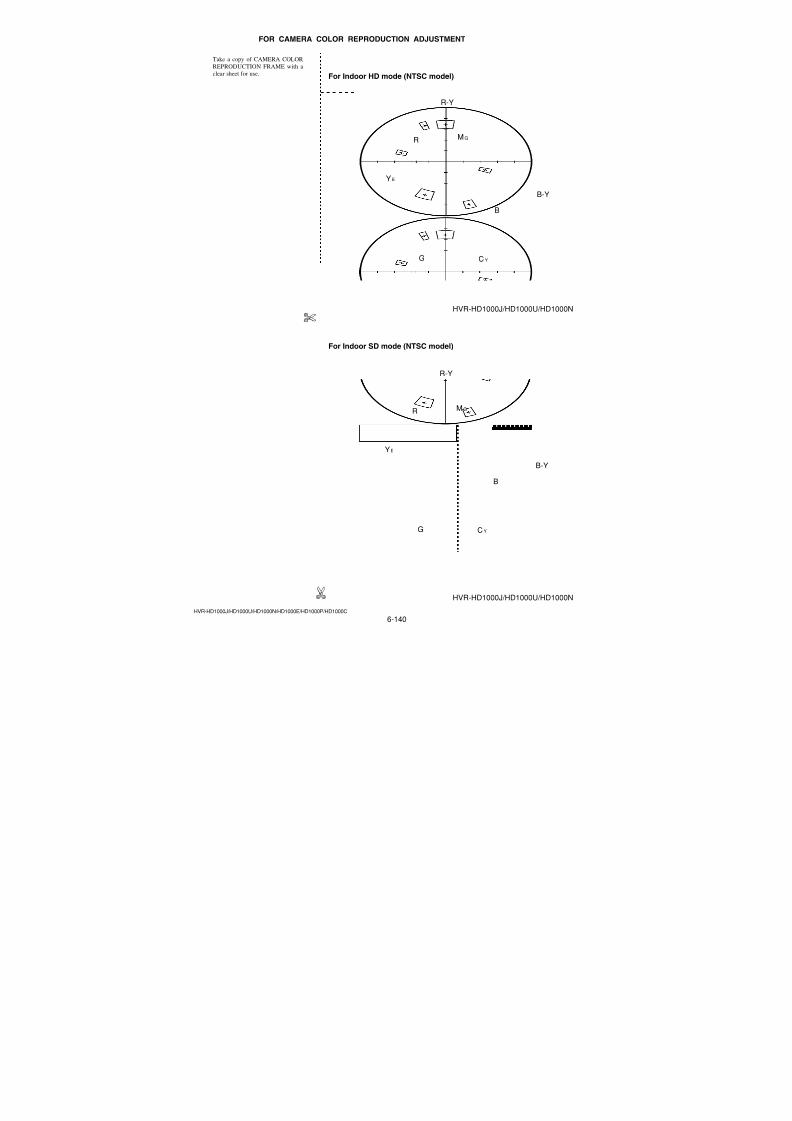
7/18/2019 SONY+HVR-HD1000 SERVICE MANUAL
http://slidepdf.com/reader/full/sonyhvr-hd1000-service-manual 278/4256-124HVR-HD1000J/HD1000U/HD1000N/HD1000E/HD1000P/HD1000C
1-5. Processing after Complete AdjustmentPerform the setting through the procedure mentioned below whenyou finish the “S VIDEO, VIDEO OUT Adjustment”.
Order Page Address Data Procedure
1 0 10 01
2C
0F 00 Press PAUSE (Write) button.(1C)
3 8 04 80 Press PAUSE (Write) button.(18)
4 8 00 00 Press PAUSE (Write) button.(18)
58
01 00 Press PAUSE (Write) button.(18)
6 8 06 00 Press PAUSE (Write) button.(18)
7 0 10 00
8 3 70 10 Press PAUSE (Write) button.
9 3 70 Check the data changes to“11”.
10 0 01 00
1-4. VIDEO OUT Level Check (VC-500 board)
Mode PLAY/EDIT
Signal No signal
Measurement Point Video terminal of A/V OUT jack
(75 Ω terminated)
Measuring Instrument OscilloscopeSpecified value Sync level: A = 286± 18 mVp-p(NTSC)
A = 300 ± 18 mVp-p(PAL)
Burst level: B = 286± 18 mVp-p(NTSC)
B = 300 ± 18 mVp-p(PAL)
Checking method:
Order Page Address Data Procedure
1 Peform “Preparations”
2 Check the sync signal level
(A) to the specified value.
3
Check the burst signal level
(B) to the specified value.
4 Perform “Processing after
Complete Adjustment”.
Fig. 6-3-5
H
B
A
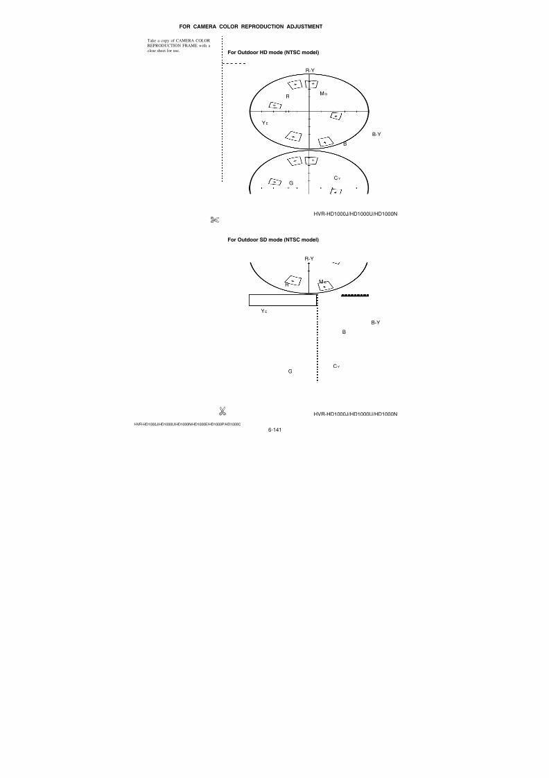
7/18/2019 SONY+HVR-HD1000 SERVICE MANUAL
http://slidepdf.com/reader/full/sonyhvr-hd1000-service-manual 279/4256-125HVR-HD1000J/HD1000U/HD1000N/HD1000E/HD1000P/HD1000C
2. COMPONENT OUT Y Level Adjustment(VC-500 board)
Mode CAMERA-TAPE
Subject Arbitrary
Measurement Point Y signal terminal of COMPONENT
OUT jack (75 Ω terminated)
Measuring Instrument Oscilloscope
Adjustment Page C
Adjustment Address 93
Specified value Y level: A = 1000 ± 10 mVp-p
Sync level: B = C = 300 ± 10 mVp-p
Switch setting:
1) REC FORMAT (Menu setting) ............................. HDV1080i
Adjusting method:
Order Page Address Data Procedure
1 0 01 01
2 3 71 01 Press PAUSE (Write) button.
3 0 10 01
48
00
Set the bit value of bit7 is
(18)“1”, and press PAUSE
(Write) button. (Note)
5 0 10 00
6 C 93
Change the data and set the
Y signal level (A) to the
specified value.
7 C 93 Press PAUSE (Write) button.
8 Check the sync signal (B, C)to the specified value.
9 0 10 01
108
00
Set the bit value of bit7 is
(18)“0”, and press PAUSE(Write) button. (Note)
11 0 10 00
12 3 70 10 Press PAUSE (Write) button.
13 3 70Check the data changes to
“11”.
14 0 01 00
Note: For the bit values, refer to “6-4. SERVICE MODE”,
“4-4. 3. Bit value discrimination”.
Fig. 6-3-6
H
A
C
B
3. COMPONENT OUT Pr Level Adjustment(VC-500 board)
Mode CAMERA-TAPE
Subject Arbitrary
Measurement Point Pr signal terminal of COMPONENT
OUT jack (75 Ω terminated)
Measuring Instrument Oscilloscope
Adjustment Page C
Adjustment Address 95
Specified value Pr level: A = 525 ± 10 mVp-p
Sync level: B = C = 300 ± 10 mVp-p
Switch setting:
1) REC FORMAT (Menu setting) ............................. HDV1080i
Adjusting method:
Order Page Address Data Procedure
1 0 01 01
2 3 71 01 Press PAUSE (Write) button.
3 0 10 01
48
00
Set the bit value of bit7 is
(18)“1”, and press PAUSE
(Write) button. (Note)
5 0 10 00
6 C 95
Change the data and set the
Y signal level (A) to the
specified value.
7 C 95 Press PAUSE (Write) button.
8 Check the sync signal (B, C)to the specified value.
9 0 10 01
108
00
Set the bit value of bit7 is
(18)“0”, and press PAUSE(Write) button. (Note)
11 0 10 00
12 3 70 10 Press PAUSE (Write) button.
13 3 70Check the data changes to
“11”.
14 0 01 00
Note: For the bit values, refer to “6-4. SERVICE MODE”, “4-4 .
3. Bit value discrimination”.
Fig. 6-3-7
H
A
C
B

7/18/2019 SONY+HVR-HD1000 SERVICE MANUAL
http://slidepdf.com/reader/full/sonyhvr-hd1000-service-manual 280/4256-126HVR-HD1000J/HD1000U/HD1000N/HD1000E/HD1000P/HD1000C
4. COMPONENT OUT Pb Level Adjustment(VC-500 board)
Mode CAMERA-TAPE
Subject Arbitrary
Measurement Point Pb signal terminal of COMPONENT
OUT jack (75 Ω terminated)
Measuring Instrument Oscilloscope
Adjustment Page C
Adjustment Address 94
Specified value Pb level: A = 525 ± 10 mVp-p
Sync level: B = C = 300 ± 10 mVp-p
Switch setting:
1) REC FORMAT (Menu setting) ............................. HDV1080i
Adjusting method:
Order Page Address Data Procedure
1 0 01 01
2 3 71 01 Press PAUSE (Write) button.
3 0 10 01
48
00
Set the bit value of bit7 is
(18)“1”, and press PAUSE
(Write) button. (Note)
5 0 10 00
6 C 94
Change the data and set the
Y signal level (A) to the
specified value.
7 C 94 Press PAUSE (Write) button.
8 Check the sync signal (B, C)to the specified value.
9 0 10 01
108
00
Set the bit value of bit7 is
(18)“0”, and press PAUSE(Write) button. (Note)
11 0 10 00
12 3 70 10 Press PAUSE (Write) button.
13 3 70Check the data changes to
“11”.
14 0 01 00
Note: For the bit values, refer to “6-4. SERVICE MODE”, “4-4.
3. Bit value discrimination”.
Fig. 6-3-8
H
A
C
B
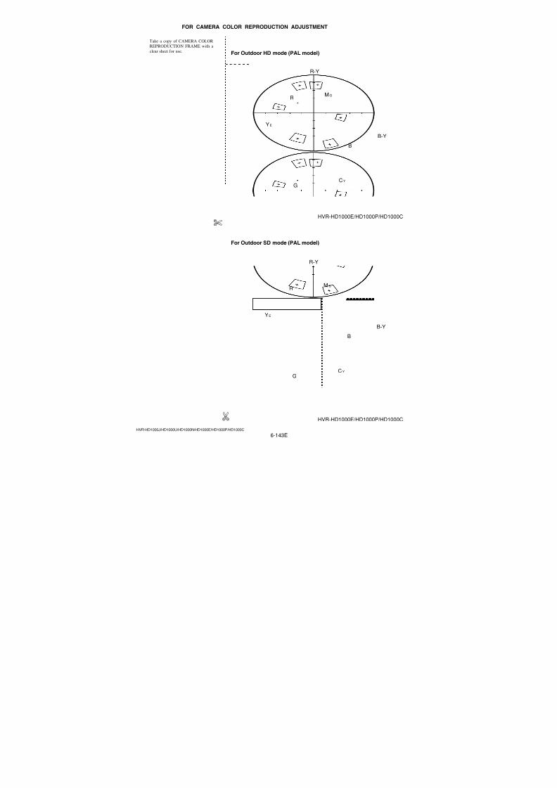
7/18/2019 SONY+HVR-HD1000 SERVICE MANUAL
http://slidepdf.com/reader/full/sonyhvr-hd1000-service-manual 281/4256-127HVR-HD1000J/HD1000U/HD1000N/HD1000E/HD1000P/HD1000C
3-5. AUDIO SYSTEM ADJUSTMENTS
[Connecting the measuring instruments for the audio]Connect the audio system measuring instruments in addition to
the video system measuring instruments as shown in Fig. 6-3-9.
Fig. 6-3-9
47 kΩ47 kΩ: 1-249-437-11
TV monitor
A/V OUT jack
Video
Audio level meter
In Playback
Main unit
VIDEO
AUDIOL
R
1. Playback Level Check
Mode VTR playback (PLAY/EDIT mode)
Signal
Alignment tape:
For audio operation check (XH5-3 (NTSC))
(XH5-3P (PAL))
Measurement PointAudio left or right terminal of A/VOUT jack
Measuring InstrumentAudio level meter and frequency
counter
Specified Value
32 kHz mode: 1 kHz, + 3.0 ± 2.0 dBs
48 kHz mode: 1 kHz, + 3.0 ± 2.0 dBs
44.1 kHz mode:
The 7.35 kHz signal level during EMPOFF is +2.0 ± 2.0 dBs.
The 7.35 kHz signal level during EMP
ON is −6 ± 2 dB from the signal level
during EMP OFF.
Checking Method:
1) Check that the playback signal level is the specified value.
7/18/2019 SONY+HVR-HD1000 SERVICE MANUAL
http://slidepdf.com/reader/full/sonyhvr-hd1000-service-manual 282/4256-128HVR-HD1000J/HD1000U/HD1000N/HD1000E/HD1000P/HD1000C
6-4. SERVICE MODE
4-1. ADJUSTMENT REMOTE COMMANDER(RM-95)
The adjustment remote commander (RM-95) is used for changingthe calculation coefficient in signal processing, EVR data, etc. The
adjustment remote commander (RM-95) performs bi-directionalcommunication with the unit using the remote commander signal
line (LANC). The resultant data of this bi-directional communica-
tion is written in the non-volatile memory.
1. Using the Adjustment Remote Commander(RM-95)
1) Connect the adjustment remote commander to the LANC ter-
minal.
2) Set the HOLD switch of the adjustment remote commander
(RM-95) to “HOLD” (SERVICE position). If it has been prop-
erly connected, the LCD on the adjustment remote commander
(RM-95) will display as shown in Fig. 6-4-1.
Fig. 6-4-1
3) Operate the adjustment remote commander (RM-95) as fol-
lows.
• Changing the pageThe page increases when the EDIT SEARCH+ button is
pressed, and decreases when the EDIT SEARCH- button is
pressed. There are altogether 16 pages, from 0 to F.
• Changing the address
The address increases when the FF (M) button is pressed,
and decreases when the REW (m) button is pressed. There
are altogether 256 addresses, from 00 to FF.• Changing the data (Data setting)
The data increases when the PLAY (N) button is pressed,
and decreases when the STOP (x) button is pressed. There
are altogether 256 data, from 00 to FF.
• Writing the adjustment data
The PAUSE button must be pressed to write the adjustment
data in the nonvolatile memory. (The new adjusting data willnot be recorded in the nonvolatile memory if this step is not
performed)
4) After completing all adjustments, turn off the main power sup-
ply (8.4 V) once.
Page Data Address
2. Precautions Upon Using the Adjustment RemoteCommander (RM-95)
Mishandling of the adjustment remote commander may erase the
correct adjustment data at times. To prevent this, it is recommended
that all adjustment data be noted down before beginning adjust-
ments and new adjustment data after each adjustment.
Hexadecimalnotation
LCD Display
Decimal notationconversion value
0 1 2 3 4 5 6 7 8 9 A B C D E F
0 1 2 3 4 5 6 7 8 9 A b c d E F
0 1 2 3 4 5 6 7 8 9 101112131415
7/18/2019 SONY+HVR-HD1000 SERVICE MANUAL
http://slidepdf.com/reader/full/sonyhvr-hd1000-service-manual 283/4256-129HVR-HD1000J/HD1000U/HD1000N/HD1000E/HD1000P/HD1000C
4-2. ADJUSTMENT REMOTE COMMANDER(NEW LANC JIG)
The adjustment remote commander (New LANC Jig) is used for
changing the calculation coefficient in signal processing, EVR data,etc. The adjustment remote commander (New LANC Jig) performs
bi-directional communication with the unit using the remote com-
mander signal line (LANC). The resultant data of this bi-direc-
tional communication is written in the non-volatile memory.
1. Using the Adjustment Remote Commander(New LANC Jig)
1) Connect the adjustment remote commander (New LANC Jig)
to the LANC terminal via the LANC cable (J-6082-442-A).
2) Set the slide switch of the adjustment remote commander (New
LANC Jig) to “SERVICE” (SERVICE position). If it has been
properly connected, the LCD on the adjustment remote com-
mander (New LANC Jig) will display as shown in Fig. 6-4-2.
Fig. 6-4-2
3) Operate the adjustment remote commander (New LANC Jig)
as follows.• Changing the page
The page increases when the Page+ (M) button is pressed,
and decreases when the Page− (m) button is pressed.• Changing the address
The address increases when the ADD+ (N) button is
pressed, and decreases when the ADD− (X) button is
pressed. There are altogether 256 addresses, from 00 to FF.• Changing the data (Data setting)
The data increases when the Data+ button is pressed, anddecreases when the Data− button is pressed. There are alto-
gether 256 data, from 00 to FF.
• Writing the adjustment data
The Write (x) button must be pressed to write the adjust-
ment data in the nonvolatile memory. (The new adjusting
data will not be recorded in the nonvolatile memory if this
step is not performed)
4) After completing all adjustments, turn off the main power sup-ply (8.4 V) once.
2. Precautions Upon Using the Adjustment RemoteCommander (New LANC Jig)
Mishandling of the adjustment remote commander (New LANC
Jig) may erase the correct adjustment data at times. To prevent
this, it is recommended that all adjustment data be noted down
before beginning adjustments and new adjustment data after each
adjustment.
Page Address Data
p:00 a:00 d:00
7/18/2019 SONY+HVR-HD1000 SERVICE MANUAL
http://slidepdf.com/reader/full/sonyhvr-hd1000-service-manual 284/4256-130HVR-HD1000J/HD1000U/HD1000N/HD1000E/HD1000P/HD1000C
Hexadecimal-decimal Conversion TableLower digit ofhexadecimal
Upper digitof hexadecimal
0 1 2 3 4 5 6 7 8 9 A
(A)
B
(b)
C
(c)
D
(d)
E
(E)
F
(F)
0
1
2
3
4
5
6
7
8
9
A (A)
B (b)
C (c)
D (d)
E (E)
F (F)
0 1 2 3 4 5 6 7 8 9 10 11 12 13 14 15
16 17 18 19 20 21 22 23 24 25 26 27 28 29 30 31
32 33 34 35 36 37 38 39 40 41 42 43 44 45 46 47
48 49 50 51 52 53 54 55 56 57 58 59 60 61 62 63
64 65 66 67 68 69 70 71 72 73 74 77 76 77 78 79
80 81 82 83 84 85 86 87 88 89 90 91 92 93 94 95
96 97 98 99 100 101 102 103 104 105 106 107 108 109 110 111
112 113 114 115 116 117 118 119 120 121 122 123 124 125 126 127
128 129 130 131 132 133 134 135 136 137 138 139 140 141 142 143
144 145 146 147 148 149 150 151 152 153 154 155 156 157 158
174
159
175160 161 162 163 164 165 166 167 168 169 170 171 172 173
177176 178 179 180 181 182 183 184 185 186 187 188 189 190 191
192 193 194 195 196 197 198 199 200 201 202 203 204 205 206 207
208 209 210 211 212 213 214 215 216 217 218 219 220 221 222 223
224 225 226 227 228 229 230 231 232 233 234 235 236 237 238 239
240 241 242 243 244 245 246 247 248 249 250 251 252 253 254 255
0
1
Note: The characters shown in the parenthesis ( ) shown the display on the adjustment remote commander.(Example) If the DDS display or the adjustment remote commander shows BD (bd);
Because the upper digit of the adjustment number is B (b), and the lower digit is D (d), the meeting point
“189” of1 and2 in the above table is the corresponding decimal number.
0
2
4-3. DATA PROCESSThe calculation of the DDS display and the adjustment remote
commander display data (hexadecimal notation) are required forobtaining the adjustment data of some adjustment items. In this
case, after converting the hexadecimal notation to decimal nota-
tion, calculate and convert the result to hexadecimal notation, and
use it as the adjustment data. Indicates the hexadecimal-decimal
conversion table.
Table 6-4-1
7/18/2019 SONY+HVR-HD1000 SERVICE MANUAL
http://slidepdf.com/reader/full/sonyhvr-hd1000-service-manual 285/4256-131HVR-HD1000J/HD1000U/HD1000N/HD1000E/HD1000P/HD1000C
4-4. SERVICE MODE
Note: Before performing the adjustment, check the data of page:0, address: 10 is “00”. If not, select page: 0, address: 00,
and set data “00”.
1. Setting the Test Mode
Page A Address 10
Data Function
00 Normal
01 Forced camera power ON (CAMERA-TAPE mode)
02 Forced VTR power ON (PLAY/EDIT mode)
03 Forced camera + VTR power ON
05Forced memory power ON
(CAMERA-MEMORY mode)
• Before setting the data , select page: 0, address: 01, and set data:
01.• For page A, the data set will be recorded in the non-volatile
memory by pressing the PAUSE (Write) button of the adjust-ment remote commander. In this case, take note that the test
mode will not be exited even when the main power is turned off
(8.4 Vdc).
• After completing adjustments/repairs, be sure to return the data
of this address to 00, and press the PAUSE (Write) button of the
adjustment remote commander. And select page: 0, address: 01,
and set data: 00.
2. Emergence Memory Address2-1. Emergence Memory Address (Mechanism
section)
Page C Address F4 to FF
Address Contents
F4 EMG code when first error occurs
F6Upper: MSW code when shift starts when first error
occurs
Lower: MSW code when first error occurs
F7Lower: MSW code to be moved when first error
occurs
F8 EMG code when second error occurs
FAUpper: MSW code when shift starts when second
error occurs
Lower: MSW code when second error occurs
FBLower: MSW code to be moved when second error
occursFC EMG code when last error occurs
FE
Upper: MSW code when shift starts when last error
occurs
Lower: MSW code when last error occurs
FFLower: MSW code to be moved when last error
occurs
When no error occurs in this unit, data “00” is written in the aboveaddresses (F4 to FF). when first error occurs in the unit, the data
corresponding to the error is written in the first emergency ad-
dress (F4 to F7). In the same way, when the second error occurs,
the data corresponding to the error is written in the second emer-
gency address (F8 to FB).Finally, when the last error occurs, the data corresponding to the
error is written in the last emergency address (FC to FF).Note: After completing adjustments, be sure to initialize the data
of addresses F4 to FF to “00”.
Initializing method:
Order Page Address Data Procedure
1 0 01 01
2 3 71 01 Press PAUSE (Write) button.
3 3 03 FF
4 3 01 37 Press PAUSE (Write) button.
5 3 02 Check the data changes to“00”.
6 3 03 Check the data changes to
“00”.
7 3 70 10 Press PAUSE (Write) button.
8 3 70 Check the data changes to
“11”.
9 0 01 00
7/18/2019 SONY+HVR-HD1000 SERVICE MANUAL
http://slidepdf.com/reader/full/sonyhvr-hd1000-service-manual 286/4256-132HVR-HD1000J/HD1000U/HD1000N/HD1000E/HD1000P/HD1000C
2-2. EMG Code (Emergency Code)Codes corresponding to the errors which occur are written in Cpage, addresses F4, F8 and FC . The type of error indicated by the
code are shown in the following table.
Code Emergency Type
00 No error
10 Loading motor emergency during loading
11 Loading motor emergency during unloading
22 T reel emergency during normal rotation
23 S reel emergency during normal rotation
24T reel emergency (Short circuit between S reel
terminal and T reel terminal)
30 FG emergency at the start up of the capstan
40 FG emergency at the start up of the drum
42 FG emergency during normal rotation of the drum
7/18/2019 SONY+HVR-HD1000 SERVICE MANUAL
http://slidepdf.com/reader/full/sonyhvr-hd1000-service-manual 287/4256-133HVR-HD1000J/HD1000U/HD1000N/HD1000E/HD1000P/HD1000C
0
0
1
0
=
2
0
1
1
1
=
7
← UNLOAD
Lock releasedCassette compartment
Pinch roller pressing
LS chassis movement section
EJ BL 0
0
1
1
=
3
0
1
1
1
=
7
ULE BL 0
0
0
1
=
1
0
1
1
1
=
7
LD1 (SR) LD2 (HL)BL 0
1
0
1
=
5
0
1
1
1
=
7
BL 0
1
0
0
=
4
0
1
1
1
=
7
STOP BL 0
1
1
0
=
6
R/P
LOAD →
← D (MSB)
← C
← B
← A (LSB)
Mechanical Position
Position
EJ
BL
ULE
LD1 (SR)
LD2 (HL)
STOP
R/P
NULL
Code
2
7
3
1
5
4
6
0
F
ContentsPosition at which the cassette component lock is released, at the farthest unload side mechanicallyat which the mechanism can move no further in the UNLOAD direction.
BLANK code, at the boundary between codes.
EJECT completion position. when the cassette is ejected, the mechanism will stop at this position.
Cassette IN standby. The guide will start protruding out as the mechanism moves towards the
LOAD position.When prepraing TOP load processing or when DEW is detected, rolling up tape by T reel ispreformed at this position.
When prepraing TOP load processing or when DEW is detected, rolling up tape by S reel is
preformed at this position.
Stop position in the loading state. The pinch roller separates, the tension regulator returns, and the
brake is imposed on both reels.
PB, REC, CUE, REVIEW, PAUSE, FF, REW positions. When pinch roller is pressed, and thetension regulator is ON, the mechanism is operating at this position in modes in which normal
images are shown.
Code not existing in the MD. Default value.
Status before finding any mechanism position.
2-3. MSW CodeMSW when errors occur:
Information on MSW (mode SW) when errors occur
MSW when movement starts:
Information on MSW when movements starts when the mechanism position is moved (When the L motor is moved)
MSW of target of movement:
Information on target MSW of movement when the mechanism position is moved
7/18/2019 SONY+HVR-HD1000 SERVICE MANUAL
http://slidepdf.com/reader/full/sonyhvr-hd1000-service-manual 288/4256-134HVR-HD1000J/HD1000U/HD1000N/HD1000E/HD1000P/HD1000C
4. Jack Check (1)
Page 7 Address FF
Note: Check that the data of page: 0, address: 10 is “00”.
Bit Function When bit value = 1 When bit value = 0
1 COMPONENT OUT jack (JK-355 board J0703) Used Not used
Using method:1) Select page: 7, address: FF.
2) By discriminating the bit value of display data, the state of jack can be discriminated.
5. Jack Check (2)
Page 3 Address CF
Note: Check that the data of page: 0, address: 10 is “00”.
Bit Function When bit value = 1 When bit value = 0
0 HDMI OUT jack (FP-867 flexible CN001) Used Not used
Using method:
1) Select page: 3, address: CF.
2) By discriminating the bit value of display data, the state of jack can be discriminated.
6. Jack Check (3)
Page 7 Address 50
Note: Check that the data of page: 0, address: 10 is “00”.
Bit Function When bit value = 1 When bit value = 0
2 MIC jack (MC-188 board J401) Used Not used
Using method:
1) Select page: 7, address: 50.
2) By discriminating the bit value of display data, the state of jack can be discriminated.
3. Bit Value DiscriminationBit values must be discriminated using the display data of the ad- justment remote commander for the following items. Us the table
below to discriminate if the bit value is “1” or “0”.
(Example) If the remote commander display is “8E”, bit value frombit 7 to bit 4 can be discriminated from the column A,and those from bit 3 to bit 0 from columnB.
Page
Address
bit3 to bit0 discrimination
bit7 to bit4 discrimination
Display on the adjustment remote commander
Display on the
adjustmentremote
commander
0
1
23
4
5
6
7
8
9
A (A)
B (b)
C (C)
D (d)
E (E)
F (F)
Bit values
bit3or
bit7
0
0
00
0
0
0
0
1
1
1
1
1
1
1
1
bit2or
bit6
0
0
00
1
1
1
1
0
0
0
0
1
1
1
1
bit1or
bit5
0
0
11
0
0
1
1
0
0
1
1
0
0
1
1
bit0or
bit4
0
1
01
0
1
0
1
0
1
0
1
0
1
0
1
A
B
7/18/2019 SONY+HVR-HD1000 SERVICE MANUAL
http://slidepdf.com/reader/full/sonyhvr-hd1000-service-manual 289/4256-135HVR-HD1000J/HD1000U/HD1000N/HD1000E/HD1000P/HD1000C
7. Jack Check (4)
Page 3 Address 61
Note: Check that the data of page: 0, address: 10 is “00”.
Bit Function When bit value = 1 When bit value = 0
6 HEADPHONE jack (HP-150 board J651) Used Not used
Using method:
1) Select page: 3, address: 61.2) By discriminating the bit value of display data, the state of jack can be discriminated.
8. Switch Check (1)
Page 2 Address 81
Note: Check that the data of page: 0, address: 10 is “00”.
Function
bit value
bit 1 bit 0
OFF 0 0
POWER MODE SW PLAY/EDIT 0 1
(PS90500) TAPE 1 0
MEMORY 1 1
Using method:
1) Select page: 2, address: 81.
2) By discriminating the bit value of display data, the state of switch can be discriminated.
9. Switch Check (2)
Page 2 Address 81
Note: Check that the data of page: 0, address: 10 is “00”.
Bit Function When bit value = 1 When bit value = 0
3 EJECT (FP-785 flexible S851) ON OFF
4 CC DOWN (Mechanism chassis) ON (DOWN) OFF (UP)
5 DISPLAY/BATT INFO (SP-048 board S0501) ON OFF
Using method:
1) Select page: 2, address: 81.
2) By discriminating the bit value of display data, the state of switch can be discriminated.
7/18/2019 SONY+HVR-HD1000 SERVICE MANUAL
http://slidepdf.com/reader/full/sonyhvr-hd1000-service-manual 290/4256-136HVR-HD1000J/HD1000U/HD1000N/HD1000E/HD1000P/HD1000C
10. Switch Check (3)
Page 7 Address 65 to 6B
Note: Check that the data of page: 0, address: 10 is “00”.
Using method:
1) Select page: 7, address: 65 to 6B.2) By discriminating the display data, the pressed key can be discriminated.
Address
65
(KEY AD0)
(IC5101 < )
66
(KEY AD1)
(IC5101 < )
67
(KEY AD2)
(IC5101 < )
68
(KEY AD3)
(IC5101 < )
69
(KEY AD4)
(IC5101 < )
6A(KEY AD5)
(IC5101 < )
6B
(KEY AD6)(IC5101 < )
00 to 0C
RECSTART/STOP
(PS90500 block)
(S101)
PHOTO
(REC)(ZM90500 block)
(S201)
−
MANUAL
(SP-048 board)
(S0504)
LCDON/OFF
(BH-001)
(S6001)
−
0D to 27
−
PHOTO
(FREEZE)(ZM90500 block)
(S202)
−
BACK
LIGHT
(SP-048 board)
(S0503)
PANELREVERSE
(RE-038 board)
(S0851)
PANEL
CLOSE
(FP-784 flexible)
(IC801)
32 to 3A
−
−
−
NIGHT SHOT
ON
(SP-048 board)
(S0502)
−
−
4F to 58
−
−
−
−
−
−
73 to 7B
−
−
−
−
−
−
8B to B7
−
−
−
−
−
−
B8 to E6
−
−
−
−
−
−
−
E7 to FF
No key input
No key input
No key input
−
NIGHT SHOT
OFF
(SP-048 board)
(S0502)
PANELNORMAL
(RE-038 board)
(S0851)
PANEL
OPEN
(FP-784 flexible)
(IC801)
Data
C5
B3
B4
D2
E2
E1
C2
REC
START/STOP
(FP-793 flexible)
ZOOM
WIDE
(FP-793 flexible)
ZOOM
TELE
(FP-793 flexible)
11. Switch Check (4)
Page 7 Address 4F
Note: Check that the data of page: 0, address: 10 is “00”.
Bit Function When bit value = 1 When bit value = 0
4 REC PROOF SW (Mechanism chassis) SAVE REC
Using method:
1) Select page: 7, address: 4F.
2) By discriminating the bit value of display data, the state of switch can be discriminated.
7/18/2019 SONY+HVR-HD1000 SERVICE MANUAL
http://slidepdf.com/reader/full/sonyhvr-hd1000-service-manual 291/4256-137HVR-HD1000J/HD1000U/HD1000N/HD1000E/HD1000P/HD1000C
12. LED, IR Light Check
Page 7 Address 00, 01 and 04
Note: Check that the data of page: 0, address: 10 is “00”.
Using method:
Order Page Address Data Procedure
1 Set the unit to CAMERA-
TAPE mode.
2 7 01 90
3 7 02 FF
4 7 04 01
5 7 00 01 Press PAUSE (Write) button.
6 7 02 Check the data changes to
“01”.
7 Check that the all LED are
lit, and that the IR light is lit.
8 7 01 90
9 7 02 FF
10 7 04 00
11 7 00 01 Press PAUSE (Write) button.
12 7 02 Check the data changes to
“01”.
13 7 00 00
14 7 01 00
13. Record of Use Check (1)
Page 7 Address A4 to AF
Note 1: This data will not be erased (reset) when the lithium 3 V
power supply (MS-379 board BT901) is removed.
Note 2: When the drum was replaced, initialize the drum rota-
tion counted time.Note 3: Check that the data of page: 0, address: 10 is “00”.
Using method:
1) The record of use data is displayed at page: 7, addresses: A4 toAF.
Address
A4
A5
A6
A7
A8
A9
AA
AB
AC
AD
AE
AF
Function
Power supplying Hour (H)
time Hour (M)
Hour (L)
(BCD code) Minute
Drum rotation Hour (H)
counted time Hour (M)
Hour (L)
(BCD code) Minute
Tape run time Hour (H)
Hour (M)
Hour (L)
(BCD code) Minute
Remarks
100000th place digit and 10000th place digit of counted time (decimal digit)
1000th place digit and 100th place digit of counted time (decimal digit)
10th place digit and 1st place digit of counted time (decimal digit)
100000th place digit and 10000th place digit of counted time (decimal digit)
1000th place digit and 100th place digit of counted time (decimal digit)
10th place digit and 1st place digit of counted time (decimal digit)
100000th place digit and 10000th place digit of counted time (decimal digit)
1000th place digit and 100th place digit of counted time (decimal digit)
10th place digit and 1st place digit of counted time (decimal digit)
7/18/2019 SONY+HVR-HD1000 SERVICE MANUAL
http://slidepdf.com/reader/full/sonyhvr-hd1000-service-manual 292/4256-138HVR-HD1000J/HD1000U/HD1000N/HD1000E/HD1000P/HD1000C
Initializing method:
Order Page Address Data Procedure
1 7 A4 00 Press PAUSE (Write) button.
2 7 A5 00 Press PAUSE (Write) button.
3 7 A6 00 Press PAUSE (Write) button.
4 7 A7 00 Press PAUSE (Write) button.5 7 A8 00 Press PAUSE (Write) button.
6 7 A9 00 Press PAUSE (Write) button.
7 7 AA 00 Press PAUSE (Write) button.
8 7 AB 00 Press PAUSE (Write) button.
9 7 AC 00 Press PAUSE (Write) button.
10 7 AD 00 Press PAUSE (Write) button.
11 7 AE 00 Press PAUSE (Write) button.
12 7 AF 00 Press PAUSE (Write) button.
14. Record of Use Check (2)
Page 7 Address 90 to 95
Note 1: This data will not be erased (reset) when the lithium 3 V
power supply (MS-379 board BT901) is removed.Note 2: When the drum was replaced, initialize the drum rota-
tion counted time.
Note 3: Check that the data of page: 0, address: 10 is “00”.
Using method:
1) The record of use data is displayed at page: 7, addresses: 90 to
95.
Initializing method:
Order Page Address Data Procedure
1 7 90 00 Press PAUSE (Write) button.
2 7 91 00 Press PAUSE (Write) button.
3 7 92 00 Press PAUSE (Write) button.
4 7 93 00 Press PAUSE (Write) button.
5 7 94 00 Press PAUSE (Write) button.
6 7 95 00 Press PAUSE (Write) button.
Address
90
91
92
93
94
95
Function
Eject count with tapeCount (H)
Count (M)(BCD code)
Count (L)
Eject count without Count (H)
tape Count (M)
(BCD code) Count (L)
Remarks
100000th place digit and 10000th place digit of Eject count (decimal digit)
1000th place digit and 100th place digit of Eject count (decimal digit)
10th place digit and 1st place digit of Eject count (decimal digit)
100000th place digit and 10000th place digit of Eject count (decimal digit)
1000th place digit and 100th place digit of Eject count (decimal digit)
10th place digit and 1st place digit of Eject count (decimal digit)
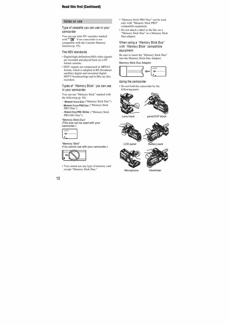
7/18/2019 SONY+HVR-HD1000 SERVICE MANUAL
http://slidepdf.com/reader/full/sonyhvr-hd1000-service-manual 293/4256-139HVR-HD1000J/HD1000U/HD1000N/HD1000E/HD1000P/HD1000C
Initializing method:
Order Page Address Data Procedure
1 7 01 C0
2 7 00 01 Press PAUSE (Write) button.
3 7 B0 to C6 Check that the data is “00”.
4 7 00 00
5 7 01 00
15. Record of Use Check (3)
Page 7 Address C8 to CD
Note 1: This data will not be erased (reset) when the lithium 3 V
power supply (MS-379 board BT901) is removed.
Note 2: Check that the data of page: 0, address 10 is “00”.
Using method:
1) The record of use data is displayed at page: 7, addresses: C8 to
CD.
16. Record of Self-diagnosis Check
Page 7 Address B0 to C6
Note 1: This data will not be erased (reset) when the lithium 3 V
power supply (MS-379 board BT901) is removed.
Note 2: Check that the data of page: 0, address 10 is “00”.
Address Self-diagnosis code
B0 “Repaired by” code (Occurred 1st time) *1
B1 “Block function” code (Occurred 1st time)
B2 “Detailed” code (Occurred 1st time)B4 “Repaired by” code (Occurred 2nd time) *1
B5 “Block function” code (Occurred 2nd time)
B6 “Detailed” code (Occurred 2nd time)
B8 “Repaired by” code (Occurred 3rd time) *1
B9 “Block function” code (Occurred 3rd time)
BA “Detailed” code (Occurred 3rd time)
BC “Repaired by” code (Occurred 4th time) *1
BD “Block function” code (Occurred 4th time)
BE “Detailed” code (Occurred 4th time)
C0 “Repaired by” code (Occurred 5th time) *1
C1 “Block function” code (Occurred 5th time)
C2 “Detailed” code (Occurred 5th time)
C4 “Repaired by” code (Occurred the last time) *1
C5 “Block function” code (Occurred the last time)
C6 “Detailed” code (Occurred the last time)
*1 : “01”t “C”, “03”t “E”
Using method:
1) The past self-diagnosis codes are displayed at page: 7, address:
BC to C6. Refer to “1-5. SELF-DIAGNOSIS FUNCTION”
for detail of the self-diagnosis code.
Address
C8
C9
CA
CB
CC
CD
Function
User initial power Year
on date Month
(BCD code) Day
Final condensation Year
occurrence date Month
(BCD code) Day
Remarks
After setting the clock, set the date of power on next
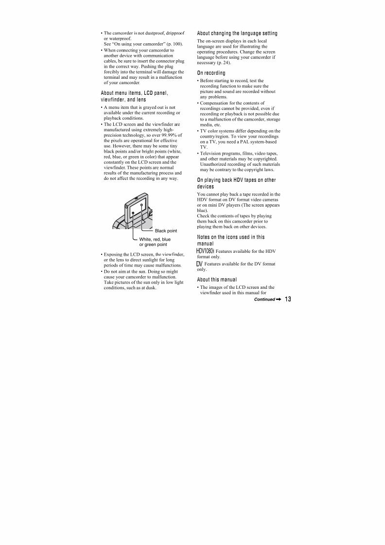
7/18/2019 SONY+HVR-HD1000 SERVICE MANUAL
http://slidepdf.com/reader/full/sonyhvr-hd1000-service-manual 294/4256-140HVR-HD1000J/HD1000U/HD1000N/HD1000E/HD1000P/HD1000C
HVR-HD1000J/HD1000U/HD1000N
FOR CAMERA COLOR REPRODUCTION ADJUSTMENT
Take a copy of CAMERA COLOR
REPRODUCTION FRAME with aclear sheet for use.
HVR-HD1000J/HD1000U/HD1000N
For Indoor HD mode (NTSC model)
For Indoor SD mode (NTSC model)
R-Y
B-Y
R
G
B
CY
YE
MG
R-Y
B-Y
R
G
B
CY
YE
MG

7/18/2019 SONY+HVR-HD1000 SERVICE MANUAL
http://slidepdf.com/reader/full/sonyhvr-hd1000-service-manual 295/4256-141HVR-HD1000J/HD1000U/HD1000N/HD1000E/HD1000P/HD1000C
HVR-HD1000J/HD1000U/HD1000N
FOR CAMERA COLOR REPRODUCTION ADJUSTMENT
Take a copy of CAMERA COLORREPRODUCTION FRAME with a
clear sheet for use.
HVR-HD1000J/HD1000U/HD1000N
For Outdoor HD mode (NTSC model)
For Outdoor SD mode (NTSC model)
R-Y
B-Y
R
G
B
MG
CY
YE
R-Y
B-Y
R
G
B
MG
CY
YE
7/18/2019 SONY+HVR-HD1000 SERVICE MANUAL
http://slidepdf.com/reader/full/sonyhvr-hd1000-service-manual 296/4256-142HVR-HD1000J/HD1000U/HD1000N/HD1000E/HD1000P/HD1000C
HVR-HD1000E/HD1000P/HD1000C
FOR CAMERA COLOR REPRODUCTION ADJUSTMENT
Take a copy of CAMERA COLORREPRODUCTION FRAME with a
clear sheet for use.
HVR-HD1000E/HD1000P/HD1000C
For Indoor HD mode (PAL model)
For Indoor SD mode (PAL model)
R-Y
B-Y
R
G
B
CY
YE
MG
R-Y
B-Y
R
G
B
CY
YE
MG
7/18/2019 SONY+HVR-HD1000 SERVICE MANUAL
http://slidepdf.com/reader/full/sonyhvr-hd1000-service-manual 297/4256-143EHVR-HD1000J/HD1000U/HD1000N/HD1000E/HD1000P/HD1000C
HVR-HD1000E/HD1000P/HD1000C
FOR CAMERA COLOR REPRODUCTION ADJUSTMENT
Take a copy of CAMERA COLORREPRODUCTION FRAME with a
clear sheet for use.
HVR-HD1000E/HD1000P/HD1000C
For Outdoor HD mode (PAL model)
For Outdoor SD mode (PAL model)
R-Y
B-Y
R
G
B
MG
CY
YE
R-Y
B-Y
R
G
B
MG
CY
YE
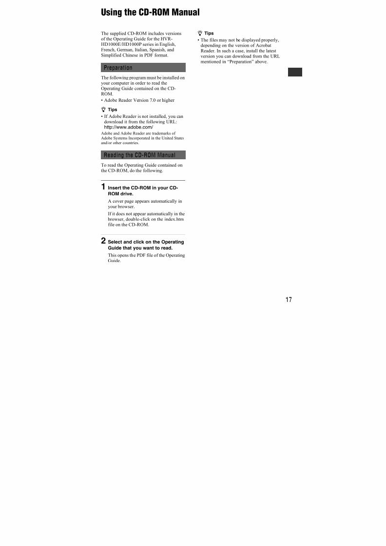
7/18/2019 SONY+HVR-HD1000 SERVICE MANUAL
http://slidepdf.com/reader/full/sonyhvr-hd1000-service-manual 298/425
3-279-638-12(1)
© 2007 Sony Corporation
Digital HD VideoCamera Recorder
Operating GuideBefore operating the unit, please read this manual thoroughly,and retain it for future reference
The supplied CD-ROM includes Operating Guide for the HVR-HD1000 series.
(English, French, German, Italian, Spanish, and Simplified Chinese versions).For more details, see “Using the CD-ROM Manual” on page 17.
HVR-HD1000E/HD1000P
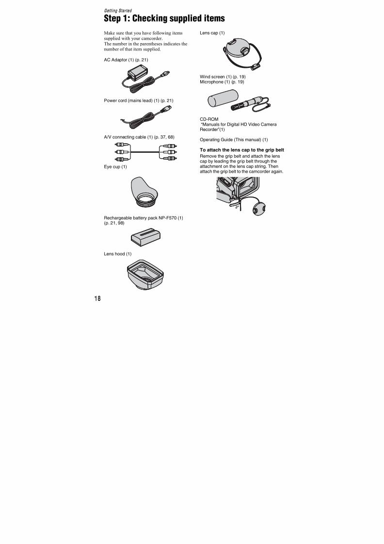
7/18/2019 SONY+HVR-HD1000 SERVICE MANUAL
http://slidepdf.com/reader/full/sonyhvr-hd1000-service-manual 299/4252
Read this first
Before operating the unit, please read this
manual thoroughly, and retain it for futurereference.
To reduce fire or shock hazard, donot expose the unit to rain ormoisture.
Replace the battery with the
specified type only. Otherwise, fire
or injury may result.
Excessive sound pressure from
earphones and headphones can
cause hearing loss.
Do not expose the batteries to
excessive heat such as sunshine,
fire or the like.
A moulded plug complying with BS 1363 is fitted
to this equipment for your safety and
convenience.
Should the fuse in the plug supplied need to be
replaced, a fuse of the same rating as the supplied
one and approved by ASTA or BSI to BS 1362(i.e., marked with an or mark) must be
used.
If the plug supplied with this equipment has a
detachable fuse cover, be sure to attach the fusecover after you change the fuse. Never use the
plug without the fuse cover. If you should lose the
fuse cover, please contact your nearest Sonyservice station.
WARNING
CAUTION
Notice for customers in theUnited Kingdom
EnglishATTENTION
The electromagnetic fields at the specific frequenciesmay influence the picture and sound of this unit.
This product has been tested and found compliant
with the limits set out in the EMC Directive
forusing connection cables shorter than 3 meters
(9.8 feet).
Notice
If static electricity or electromagnetism causes
data transfer to discontinue midway (fail), restartthe application or disconnect and connect the
communication cable (USB, etc.) again.
Notice for the customers in thecountries applying EU Directives
The manufacturer of this product is Sony
Corporation, 1-7-1 Konan Minato-ku Tokyo, 108-0075 Japan. The Authorized Representative for
EMC and product safety is Sony Deutschland
GmbH, Hedelfinger Strasse 61,70327 Stuttgart,
Germany. For any service or guarantee matters, please refer to the addresses given in separate
service or guarantee documents.
Disposal of Waste
Electrical and ElectronicEquipment for business use(Applicable in the European
Union and other Europeancountries with separatecollection systems)
This symbol on the product or on its packaging
indicates that this product shall not be treated as
household waste. Instead it shall be handed over
to the applicable take-back scheme for the
recycling of electrical and electronic equipment.
By ensuring this product is disposed of correctly,
you will help prevent potential negative
consequences for the environment and humanhealth, which could otherwise be caused byinappropriate waste handling of this product.
The recycling of materials will help to conserve
natural resources. For more detailed information
FOR CUSTOMERS IN EUROPE
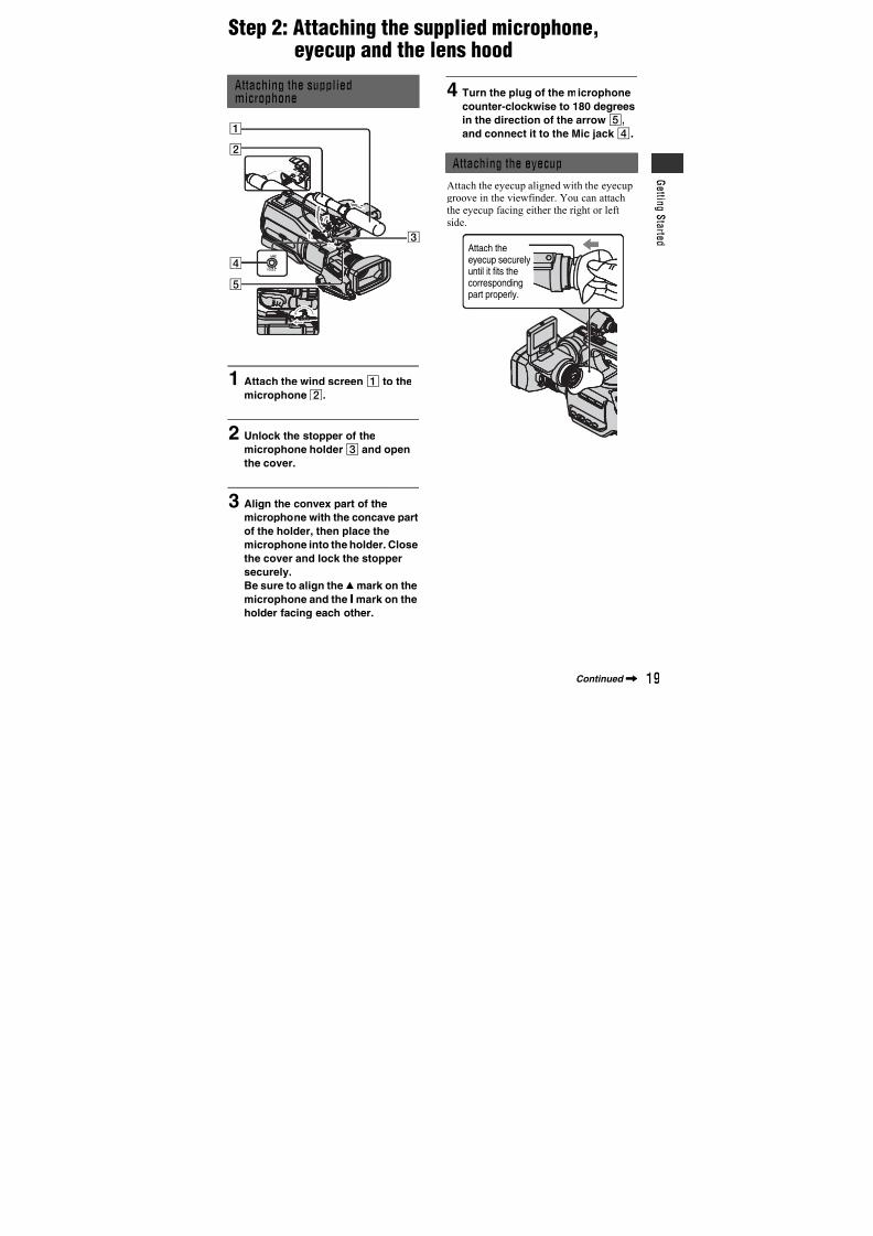
7/18/2019 SONY+HVR-HD1000 SERVICE MANUAL
http://slidepdf.com/reader/full/sonyhvr-hd1000-service-manual 300/4253
about recycling of this product, please contact
your local Sony office or visit Sony Europe’s web
site for business customers:
http://www.sonybiz.net/environment
Disposal of waste
batteries (applicable inthe European Union andother European countries
with separate collectionsystems)
This symbol on the battery or on the packaging
indicates that the battery provided with this
product shall not be treated as household waste.By ensuring these batteries are disposed of
correctly, you will help prevent potentially
negative consequences for the environment andhuman health which could otherwise be caused by
inappropriate waste handling of the battery. The
recycling of the materials will help to conservenatural resources.
In case of products that for safety, performance or
data integrity reasons require a permanent
connection with an incorporated battery, this
battery should be replaced by qualified servicestaff only.
To ensure that the battery will be treated properly,hand over the product at end-of-life to the
applicable collection point for the recycling of
electrical and electronic equipment.
For all other batteries, please view the section onhow to remove the battery from the product
safely. Hand the battery over to the applicable
collection point for the recycling of waste batteries.
For more detailed information about recycling ofthis product or battery, please contact your local
Civic Office, your household waste disposalservice or the shop where you purchased the
product.
Verwijdering van oudebatterijen (in de EuropeseUnie en andere Europeselanden met afzonderlijkeinzamelingssystemen)
Dit symbool op de batterij of verpakking wijst
erop dat de meegeleverde batterij van dit product
niet als huishoudelijk afval behandeld mag
worden.Door deze batterijen op juiste wijze af te voeren,voorkomt u voor mens en milieu negatieve
gevolgen die zich zouden kunnen voordoen in
geval van verkeerde afvalbehandeling. Het
recycleren van materialen draagt bij tot het
vrijwaren van natuurlijke bronnen.
In het geval dat de producten om redenen van
veiligheid, prestaties dan wel in verband met data-
integriteit een permanente verbinding met batterij
vereisen, dient deze batterij enkel door
gekwalificeerd servicepersoneel vervangen teworden. Om ervoor te zorgen dat de batterij op
een juiste wijze zal worden behandeld, dient het
product aan het eind van zijn levenscyclus
overhandigd te worden aan het desbetreffende
inzamelingspunt voor de recyclage van elektrischen elektronisch materiaal.
Voor alle andere batterijen verwijzen we u naarhet gedeelte over hoe de batterij veilig uit het
product te verwijderen. Overhandig de batterij bij
het desbetreffende inzamelingspunt voor de
recyclage van batterijen.Voor meer details in verband met het recyclen van
dit product of batterij, neemt u contact op met degemeentelijke instanties, het bedrijf of de dienst
belast met de verwijdering van huishoudafval of
de winkel waar u het product hebt gekocht.
For the customers in theNederlandVoor de klanten in Nederland
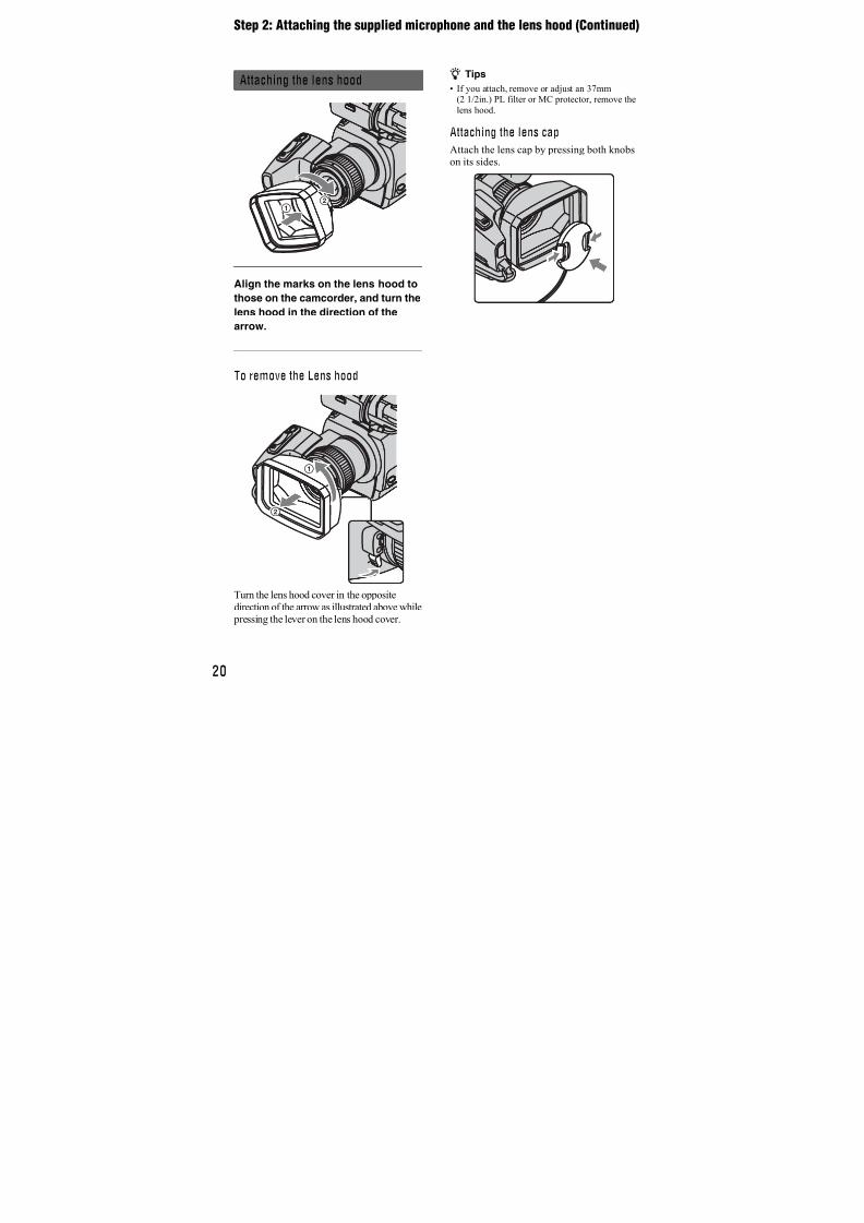
7/18/2019 SONY+HVR-HD1000 SERVICE MANUAL
http://slidepdf.com/reader/full/sonyhvr-hd1000-service-manual 301/4254
If you have any questions about this product, you
may call:
Sony Customer Information Center 1-800-686SONY (7669).
The number below is for the FCC related matters
only.
Regulatory Information
CAUTION
You are cautioned that any changes ormodifications not expressly approved in this
manual could void your authority to operate this
equipment.
Notes
This equipment has been tested and found to
comply with the limits for a Class B digital
device, pursuant to Part 15 of the FCC Rules.
These limits are designed to provide reasonable
protection against harmful interference in a
residential installation. This equipment generates,uses, and can radiate radio frequency energy and,
if not installed and used in accordance with the
instructions, may cause harmful interference toradio communications.
However, there is no guarantee that interference
will not occur in a particular installation. If this
equipment does cause harmful interference toradio or television reception, which can be
determined by turning the equipment off and on,
the user is encouraged to try to correct the
interference by one or more of the followingmeasures:
– Reorient or relocate the receiving antenna.
– Increase the separation between the equipment
and receiver.
– Connect the equipment into an outlet on acircuit different from that to which the receiver
is connected.
– Consult the dealer or an experienced radio/TV
technician for help.
The supplied interface cable must be used with the
equipment in order to comply with the limits for adigital device pursuant to Subpart B of Part 15 of
FCC Rules.
Battery pack
This device complies with Part 15 of the FCCRules. Operation is subject to the following two
conditions:
(1) This device may not cause harmful
interference, and (2) this device must accept anyinterference received, including interference that
may cause undesired operation.
For customers in the U.S.A.
Declaration of Conformity
Trade Name: SONY
Model No.: HVR-HD1000P
Responsible Party: Sony Electronics Inc.
Address: 16530 Via Esprillo, San Diego, CA
92127 U.S.A
Telephone number: 858-942-2230
This device complies with Part 15 of the FCCRules.
Operation is subject to the following two
conditions:
(1) This device may not cause harmful
interference, and (2) this device must accept any
interference received, including interference
that may cause undesired operation.
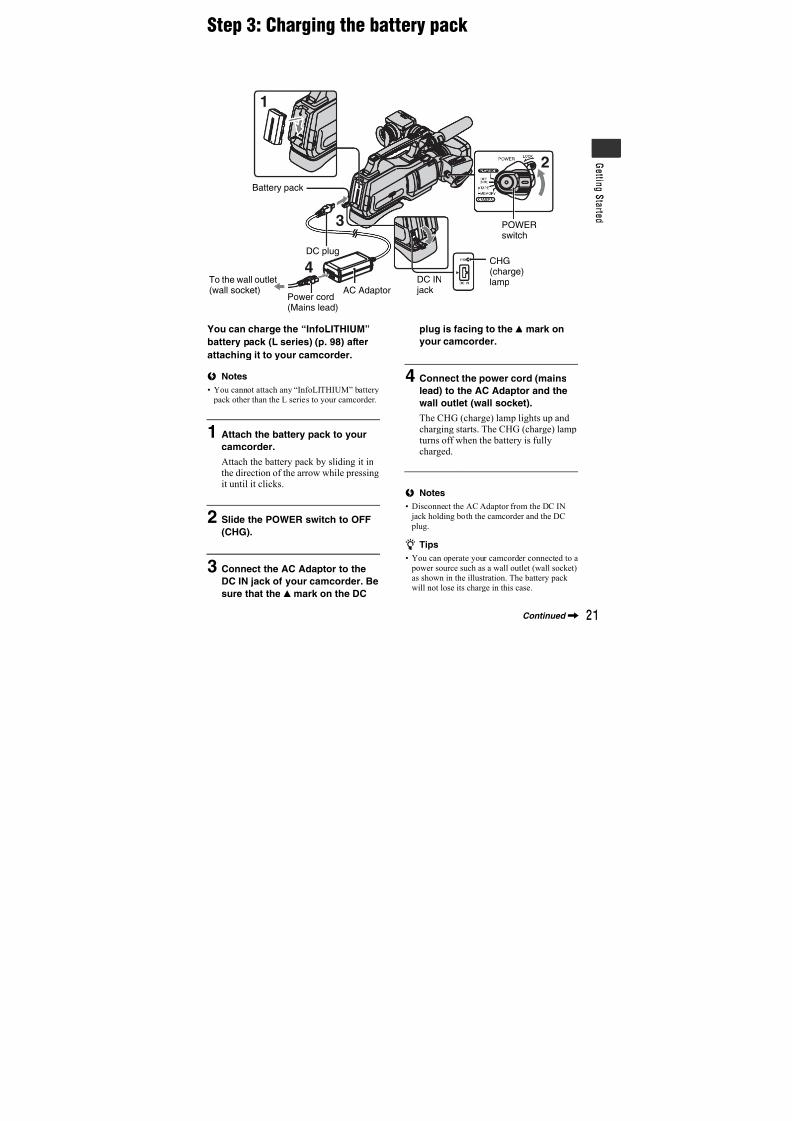
7/18/2019 SONY+HVR-HD1000 SERVICE MANUAL
http://slidepdf.com/reader/full/sonyhvr-hd1000-service-manual 302/4255
Dieses Produkt wurde geprüft und erfüllt die
EMV-Richtlinie, sofern Verbindungskabel mit
einer Länge von weniger als 3 Metern verwendet
werden.
Hinweis
Wenn eine Datenübertragung aufgrund statischer
oder elektromagnetischer Störeinflüsse abbricht
(fehlschlägt), starten Sie die entsprechende
Anwendung neu, oder entfernen Sie das USB-
Kabel, und schließen Sie es wieder an.
• Verwenden Sie das Netzteil nicht, wenn nur
wenig Platz vorhanden ist, z.B. zwischen einer
Wand und Möbelstücken.
Continued,
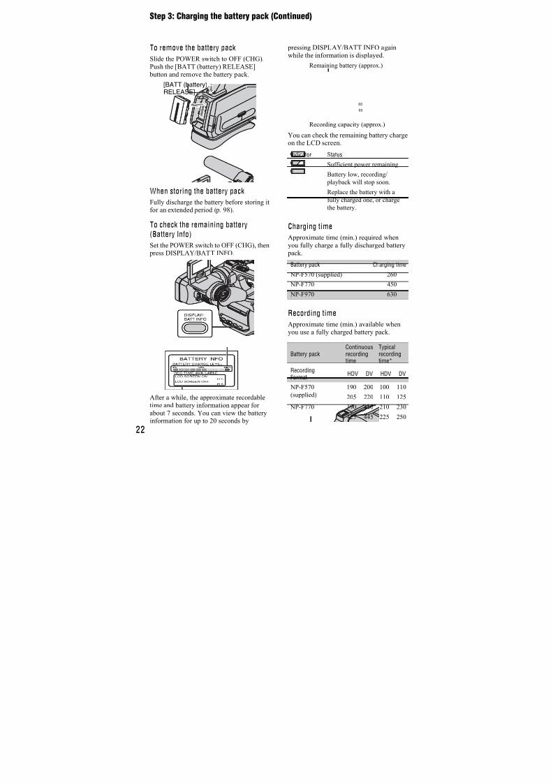
7/18/2019 SONY+HVR-HD1000 SERVICE MANUAL
http://slidepdf.com/reader/full/sonyhvr-hd1000-service-manual 303/4256
Entsorgung vongebrauchten Batterien undAkkus (anzuwenden in denLändern der EuropäischenUnion und andereneuropäischen Ländern miteinem separatenSammelsystem für dieseProdukte)
Das Symbol auf der Batterie/dem Akku oder der
Verpackung weist darauf hin, dass diese nicht als
normaler Haushaltsabfall zu behandeln sind.
Durch Ihren Beitrag zum korrekten Entsorgendieser Batterien/Akkus schützen Sie die Umwelt
und die Gesundheit Ihrer Mitmenschen. Umwelt
und Gesundheit werden durch falsches
Entsorgen gefährdet. Materialrecycling hilft, den
Verbrauch von Rohstoffen zu verringern.
Bei Produkten, die auf Grund ihrer Sicherheit, der
Funktionalität oder als Sicherung vor
Datenverlust eine ständige Verbindung zureingebauten Batterie benötigen, sollte die Batterienur durch qualifiziertes Servicepersonal
ausgetauscht werden.
Um sicherzustellen, dass die Batterie korrektentsorgt wird, geben Sie das Produkt zwecks
Entsorgung an einer Annahmestelle für dasRecycling von elektrischen und elektronischen
Geräten ab.
Für alle anderen Batterien entnehmen Sie die
Batterie bitte entsprechend dem Kapitel über die
sichere Entfernung der Batterie. Geben Sie dieBatterie an einer Annahmestelle für das Recycling
von Batterien/Akkus ab.
Weitere Informationen über das Recycling dieses
Produkts oder der Batterie erhalten Sie von Ihrer
Gemeinde, den kommunalen
Entsorgungsbetrieben oder dem Geschäft, in dem
Sie das Produkt gekauft haben.
Read this first (Continued)
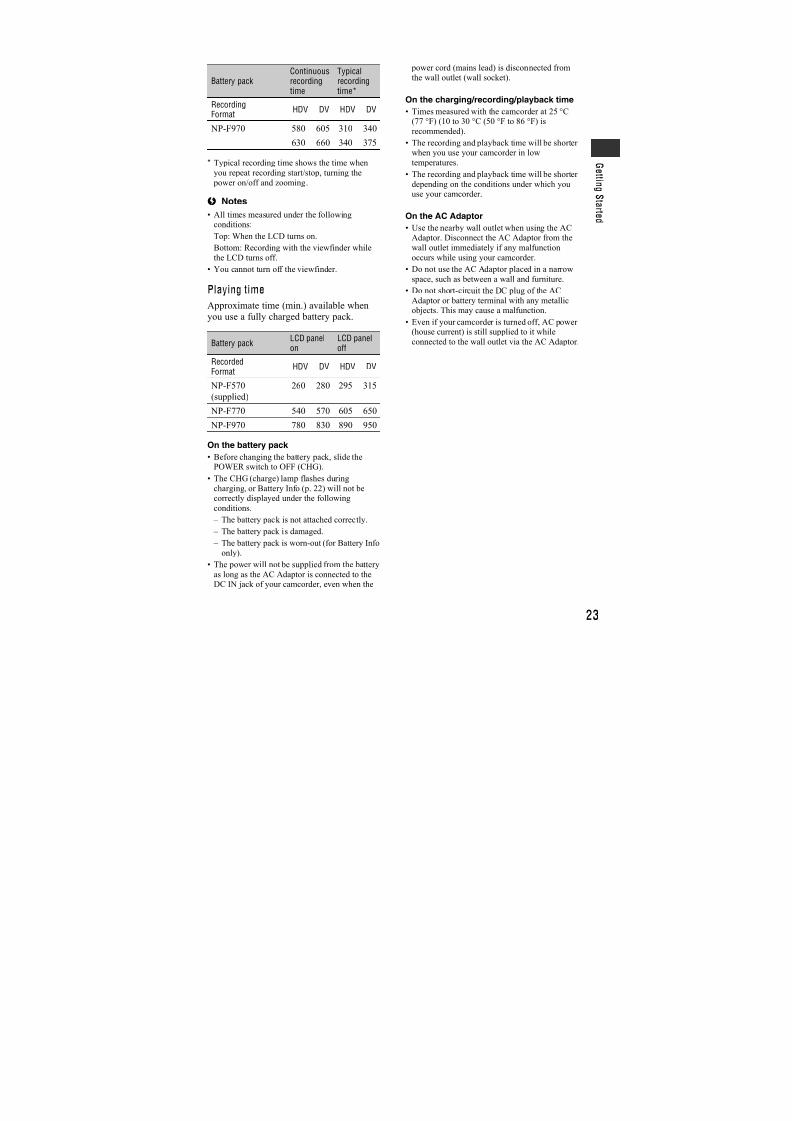
7/18/2019 SONY+HVR-HD1000 SERVICE MANUAL
http://slidepdf.com/reader/full/sonyhvr-hd1000-service-manual 304/4257
Este producto se ha probado y cumple con la
normativa que establece la Directiva EMC si se
utiliza un cable de conexión de menos de 3 metros
de longitud.
AvisoSi la electricidad estática o el electromagnetismo
interrumpen la transmisión de datos (fallo),
reinicie la aplicación o desconecte el cable de
comunicación (USB, etc.) y vuelva a conectarlo.
Continued,
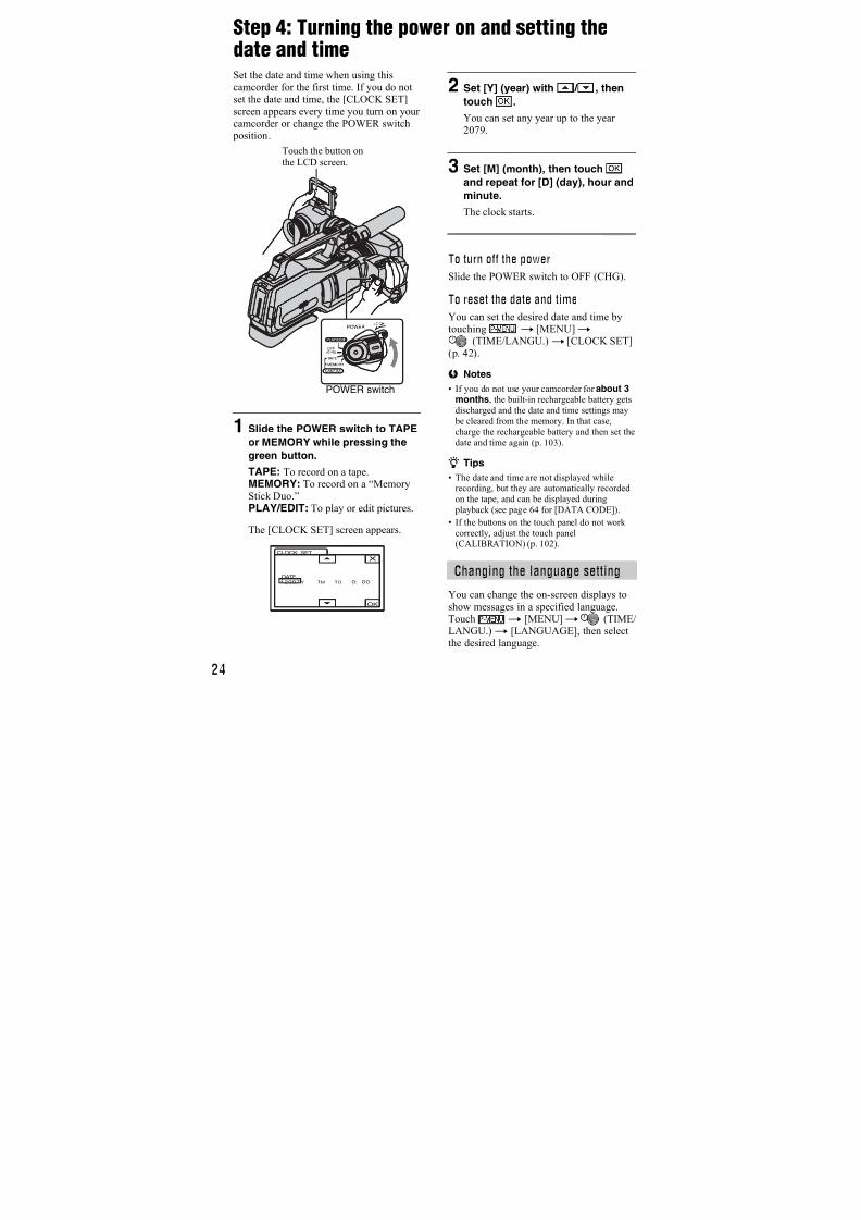
7/18/2019 SONY+HVR-HD1000 SERVICE MANUAL
http://slidepdf.com/reader/full/sonyhvr-hd1000-service-manual 305/4258
Tratamiento de lasbaterías al final de su vidaútil (aplicable en la UniónEuropea y en paíseseuropeos con sistemas derecogida selectiva deresiduos)
Este símbolo en la batería o en el embalaje indica
que la batería proporcionada con este producto no
puede ser tratada como un residuo doméstico
normal.Al asegurarse de que estas baterías se desechan
correctamente, Ud. ayuda a prevenir las
consecuencias negativas para el medio ambiente y
la salud humana que podrían derivarse de la
incorrecta manipulación en el momento de
deshacerse de la batería. El reciclaje de materialesayuda a conservar los recursos naturales.
En el caso de productos que por razones de
seguridad, rendimiento o mantenimiento de datos,sea necesaria una conexión permanente con la
batería incorporada, esta batería solo deberá serreemplazada por personal técnico cualificado paraello.
Para asegurarse de que la batería será tratadacorrectamente,entregue el producto al final de su
vida útil en un punto de recogida para el reciclado
de aparatos eléctricos y electrónicos.
Para las demás baterías,vea la sección donde se
indica cómo quitar la batería del producto de
forma segura. Deposite la batería en elcorrespondiente punto de recogida para el
reciclado.
Para recibir información detallada sobre el
reciclaje de este producto o de la batería, póngaseen contacto con el ayuntamiento, el punto de
recogida más cercano o el establecimiento donde
ha adquirido el producto.
Read this first (Continued)
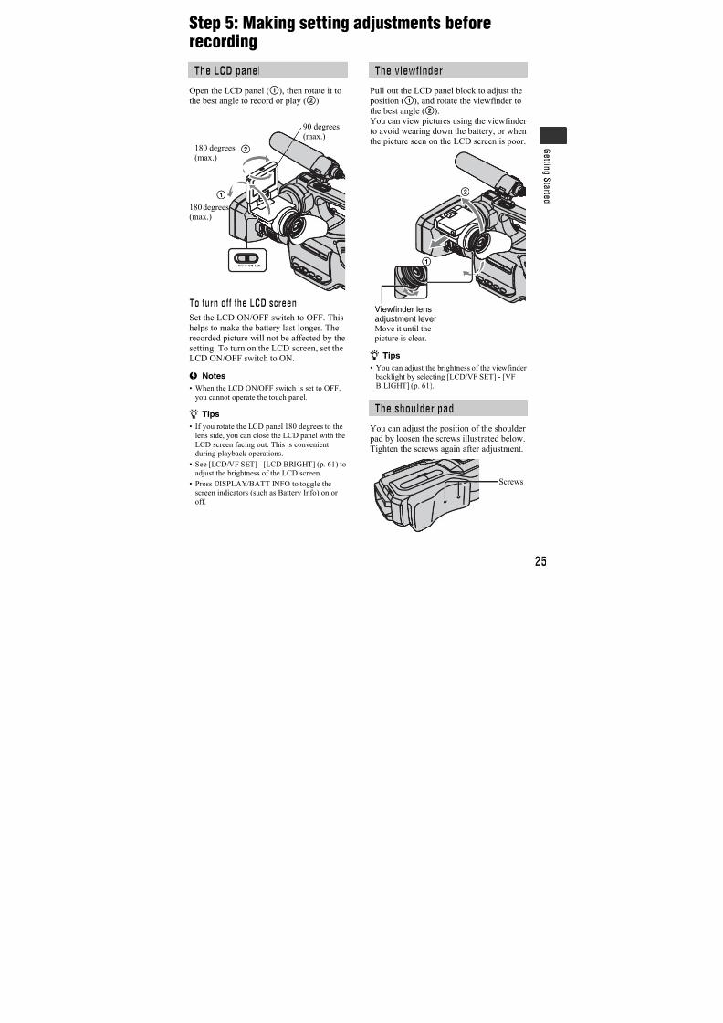
7/18/2019 SONY+HVR-HD1000 SERVICE MANUAL
http://slidepdf.com/reader/full/sonyhvr-hd1000-service-manual 306/4259
Cet appareil a été testé et jugé conforme aux
limites établies par la directive EMC visant
l’utilisation de câbles de connexion de moins de 3
mètres.
Avis
Si l’électricité statique ou les champsélectrostatiques entraînent une interruption lors du
transfert des données (échec), redémarrez
l’application ou débranchez, puis rebranchez le
câble de connexion (USB, etc.).
• N’utilisez pas un adaptateur secteur suité dans
un espace restreint, par exemple un mur et un
meuble.
Elimination des piles etaccumulateurs usagés(Applicable dans les paysde l’Union Européenne etaux autres pays européensdisposant de systèmes decollecte sélective)
Ce symbole, apposé sur les piles et accumulateurs
ou sur les emballages, indique que les piles et
accumulateurs fournis avec ce produit ne doivent
pas être traités comme de simples déchets
Continued,
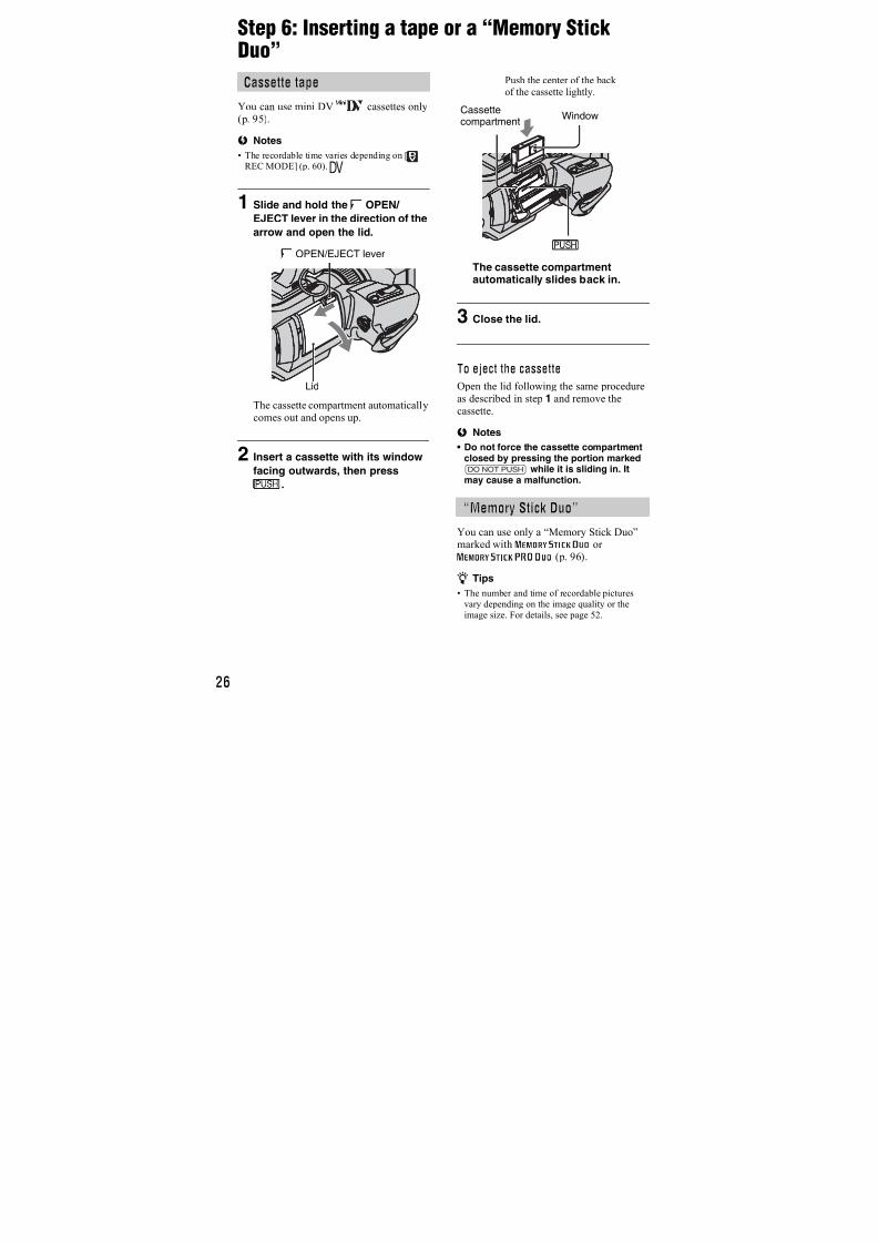
7/18/2019 SONY+HVR-HD1000 SERVICE MANUAL
http://slidepdf.com/reader/full/sonyhvr-hd1000-service-manual 307/42510
ménagers. En vous assurant que ces piles et
accumulateurs sont mis au rebut de façon
appropriée, vous participez activement à la
prévention des conséquences négatives que leur
mauvais traitement pourrait provoquer sur
l’environnement et sur la santé humaine. Le
recyclage des matériaux contribue par ailleurs à la préservation des ressources naturelles.
Pour les produits qui pour des raisons de sécurité,
de performance ou d’intégrité de donnéesnécessitent une connexion permanente à une pile
ou à un accumulateur, il conviendra de vous
rapprocher d’un service technique qualifié poureffectuer son remplacement.
En rapportant votre appareil électrique en fin de
vie à un point de collecte approprié vous vousassurez que la pile ou l'accumulateur incorporé
sera traitée correctement.
Pour tous les autres cas de figure et afin d’enlever
les piles ou accumulateurs en toute sécurité de
votre appareil, reportez-vous au manuel
d’utilisation. Rapporter les piles ou accumulateurs
usagés au point de collecte approprié pour le
recyclage.
Pour toute information complémentaire au sujet
du recyclage de ce produit ou des piles et
accumulateurs, vous pouvez contacter votremunicipalité, votre déchetterie locale ou le point
de vente où vous avez acheté ce produit.
Il presente prodotto è stato testato ed è risultato
conforme ai limiti stabiliti dalla Direttiva EMC
relativa all’uso dei cavi di collegamento di
lunghezza inferiore a 3 metri.
Nota
Se l’elettricità statica o interferenze magnetiche
causano l’interruzione del trasferimento dei dati,
che pertanto non avviene, è necessario riavviare
l’applicazione oppure scollegare, quindi
ricollegare il cavo.
Read this first (Continued)
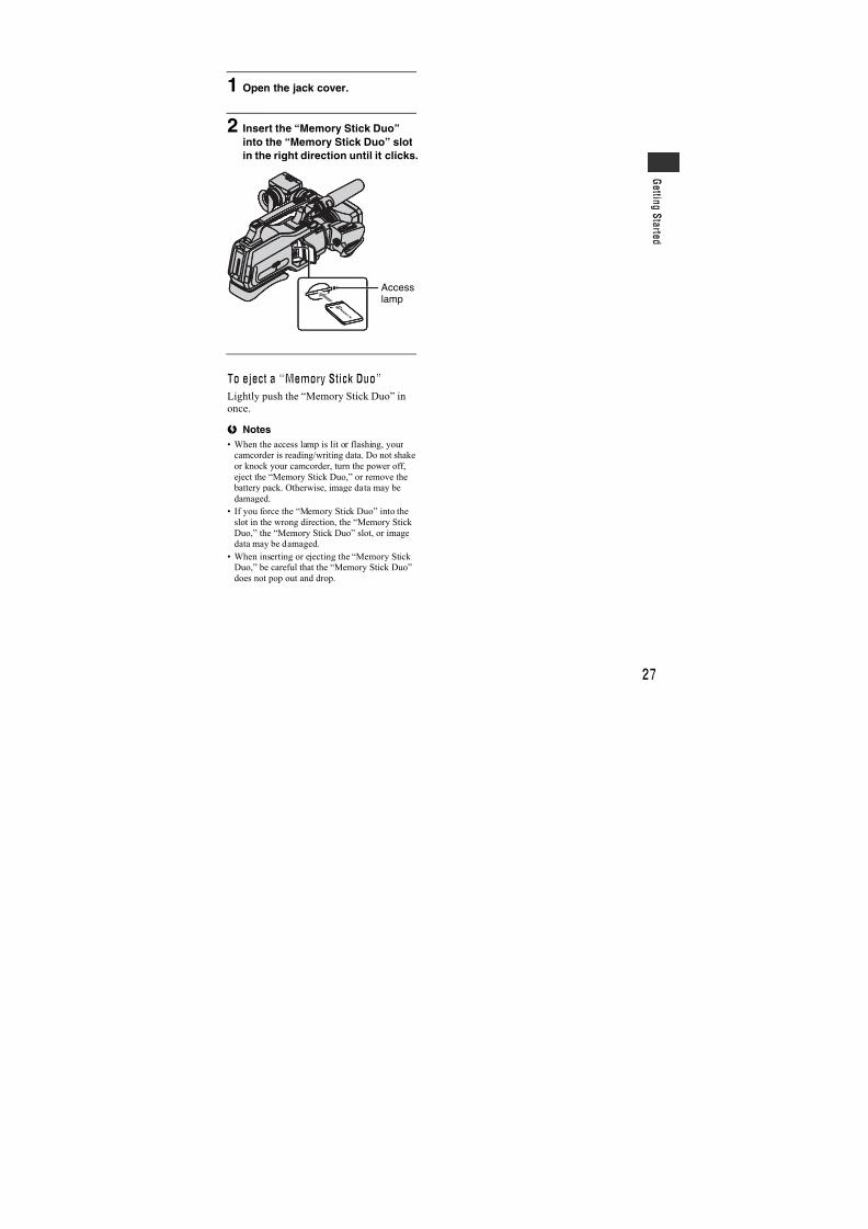
7/18/2019 SONY+HVR-HD1000 SERVICE MANUAL
http://slidepdf.com/reader/full/sonyhvr-hd1000-service-manual 308/42511
Trattamento delle pileesauste (applicabile intutti i paesi dell’UnioneEuropea e in altri paesiEuropei con sistema diraccolta differenziata)
Questo simbolo sul prodotto o sulla confezioneindica che la pila non deve essere considerata un
normale rifiuto domestico.
Assicurandovi che le pile siano smaltite
correttamente, contribuirete a prevenire potenziali
conseguenze negative per l’ambiente e per lasalute che potrebbero altrimenti essere causate dal
loro inadeguato smaltimento.
Il riciclaggio dei materiali aiuta a conservare lerisorse naturali.
In caso di prodotti che per motivi di sicurezza,
prestazione o protezione dei dati richiedano un
collegamento fisso ad una pila interna, la stessa
dovrà essere sostituita solo da personale di
assistenza qualificato.
Consegnare il prodotto a fine vita al punto di
raccolta idoneo allo smaltimento di
apparecchiature elettriche ed elettroniche; questo
assicura che anche la pila al suo interno venga
trattata correttamente.
Per le altre pile consultate la sezione relativa alla
rimozione sicura delle pile. Conferire le pileesauste presso i punti di raccolta indicati per il
riciclo.
Per informazioni più dettagliate circa lo
smaltimento della pila esausta o del prodotto,
potete contattare il Comune, il servizio locale dismaltimento rifiuti oppure il negozio dove l’avete
acquistato.
Continued,
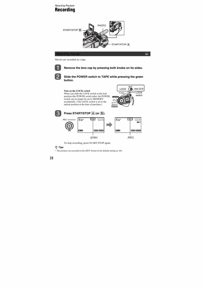
7/18/2019 SONY+HVR-HD1000 SERVICE MANUAL
http://slidepdf.com/reader/full/sonyhvr-hd1000-service-manual 309/42512
Type of cassette you can use in your
camcorderYou can use mini DV cassettes markedwith . Your camcorder is notcompatible with the Cassette Memoryfunction (p. 95).
The HDV standards
• Digital high-definition (HD) video signalsare recorded and played back on a DVformat cassette.
• HDV signals are compressed in MPEG2format, which is adopted in BS (broadcastsatellite) digital and terrestrial digitalHDTV broadcastings and in Blu-ray discrecorders.
Types of “Memory Stick” you can usein your camcorder
You can use “Memory Stick” marked with
the following (p. 96). – (“Memory Stick Duo”)
– (“Memory StickPRO Duo”)
– (“Memory StickPRO-HG Duo”).
“Memory Stick Duo”(This size can be used with yourcamcorder.)
“Memory Stick”(You cannot use with your camcorder.)
• You cannot use any type of memory cardexcept “Memory Stick Duo.”
• “Memory Stick PRO Duo” can be usedonly with “Memory Stick PRO”compatible equipment.
• Do not attach a label or the like on a
“Memory Stick Duo” or a Memory StickDuo adaptor.
When using a “Memory Stick Duo”with “Memory Stick” compatible
equipment
Be sure to insert the “Memory Stick Duo”into the Memory Stick Duo Adaptor.
Memory Stick Duo Adaptor
Using the camcorder
• Do not hold the camcorder by thefollowing parts.
Notes on use
LCD panel
Viewfinder
Lens hood
Microphone
Battery pack
panel EVF block
Read this first (Continued)
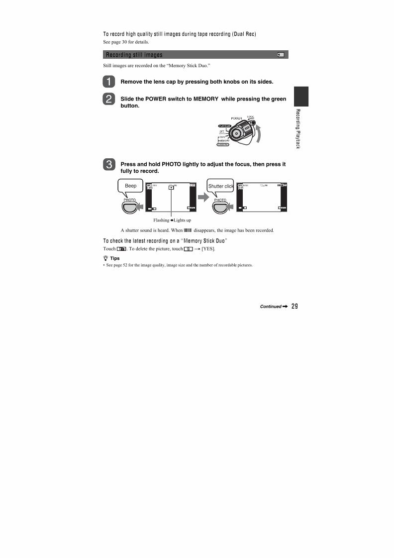
7/18/2019 SONY+HVR-HD1000 SERVICE MANUAL
http://slidepdf.com/reader/full/sonyhvr-hd1000-service-manual 310/42513
• The camcorder is not dustproof, dripproofor waterproof.See “On using your camcorder” (p. 100).
• When connecting your camcorder to
another device with communicationcables, be sure to insert the connector plugin the correct way. Pushing the plugforcibly into the terminal will damage theterminal and may result in a malfunctionof your camcorder.
About menu items, LCD panel,viewfinder, and lens
• A menu item that is grayed out is notavailable under the current recording or playback conditions.
• The LCD screen and the viewfinder aremanufactured using extremely high-
precision technology, so over 99.99% ofthe pixels are operational for effectiveuse. However, there may be some tiny
black points and/or bright points (white,red, blue, or green in color) that appear
constantly on the LCD screen and theviewfinder. These points are normalresults of the manufacturing process anddo not affect the recording in any way.
• Exposing the LCD screen, the viewfinder,or the lens to direct sunlight for long
periods of time may cause malfunctions.
• Do not aim at the sun. Doing so mightcause your camcorder to malfunction.Take pictures of the sun only in low lightconditions, such as at dusk.
About changing the language setting
The on-screen displays in each locallanguage are used for illustrating theoperating procedures. Change the screenlanguage before using your camcorder ifnecessary (p. 24).
On recording
• Before starting to record, test therecording function to make sure the
picture and sound are recorded withoutany problems.
• Compensation for the contents of
recordings cannot be provided, even ifrecording or playback is not possible dueto a malfunction of the camcorder, storagemedia, etc.
• TV color systems differ depending on thecountry/region. To view your recordingson a TV, you need a PAL system-basedTV.
• Television programs, films, video tapes,and other materials may be copyrighted.
Unauthorized recording of such materialsmay be contrary to the copyright laws.
On playing back HDV tapes on otherdevices
You cannot play back a tape recorded in theHDV format on DV format video camerasor on mini DV players (The screen appears
blue).
Check the contents of tapes by playingthem back on this camcorder prior to playing them back on other devices.
Notes on the icons used in thismanual
Features available for the HDVformat only.
Features available for the DV formatonly.
About this manual
• The images of the LCD screen and theviewfinder used in this manual for
Black point
White, red, blueor green point
Continued,
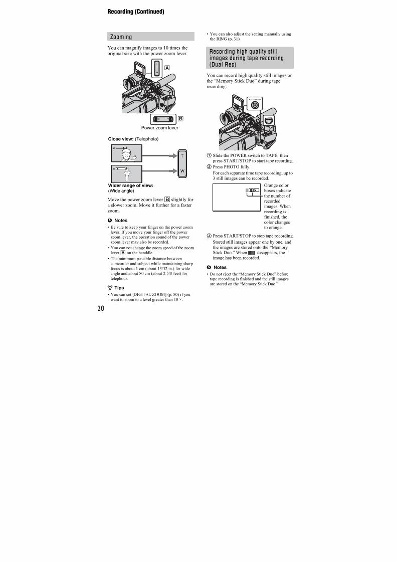
7/18/2019 SONY+HVR-HD1000 SERVICE MANUAL
http://slidepdf.com/reader/full/sonyhvr-hd1000-service-manual 311/42514
illustration purposes are captured using adigital still camera, and therefore mayappear different.
• Design and specifications of recording
media and other accessories are subject tochange without notice.
About the Carl Zeiss lens
Your camcorder is equipped with a CarlZeiss lens, which was developed jointly byCarl Zeiss, in Germany, and SonyCorporation, and produces superior images.It adopts the MTF measurement system forvideo cameras and offers a quality typicalof a Carl Zeiss lens. Also, the lens for yourcamcorder is T -coated to suppressunwanted reflections and faithfullyreproduce colors.MTF= Modulation Transfer FunctionThe number value indicates the amount oflight from a subject coming into the lens.
Read this first (Continued)
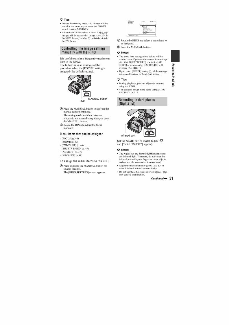
7/18/2019 SONY+HVR-HD1000 SERVICE MANUAL
http://slidepdf.com/reader/full/sonyhvr-hd1000-service-manual 312/42515
Table of Contents
Read this first ..................................2Notes on use ................................. 12
Using the CD-ROM Manual ..........17
Step 1: Checking supplied items ... 18
Step 2: Attaching the suppliedmicrophone, eyecup and the lenshood ............................................19
Step 3: Charging the battery pack.....................................................21
Step 4: Turning the power on andsetting the date and time ............24Changing the language setting .... 24
Step 5: Making setting adjustmentsbefore recording ..........................25
Step 6: Inserting a tape or a “MemoryStick Duo” ...................................26
Recording .....................................28Zooming ...................................... 30Recording high quality still images
during tape recording (Dual Rec)................................................... 30
Controlling the image settingsmanually with the RING ............ 31
Recording in dark places(NightShot) ............................... 31
Adjusting the exposure for backlitsubjects .................................... 32
Recording in mirror mode ........... 32
Playback .......................................33Using PB zoom ........................... 35
Searching for the starting point .....36Searching for the last scene of the
most recent recording (ENDSEARCH) .................................. 36
Reviewing the most recentlyrecorded scenes (Rec review)................................................... 36
Playing the picture on a TV ...........37Connecting to a high definition TV
................................................... 38Connecting to a 16:9 (wide) or 4:3 TV
................................................... 39
Using the menu items ..........42 Menu items ...................................43
CAMERA SET menu ...............45
Settings to adjust your camcorder tothe recording conditions
MEMORY SET menu .............52
Settings for the “Memory Stick Duo”
PICT.APPLI. menu ................55
Special effects on pictures oradditional functions on recording/ playback
EDIT/PLAY menu ..................58
Settings for editing or playing back invarious modes
STANDARD SET menu .........59Settings while recording on a tape or
other basic settings
TIME/LANGU. menu ..............65
Customizing Personal Menu .........66
Dubbing to VCR or DVD/HDDrecorders .....................................68
Recording pictures from a VCR ....71
Dubbing pictures from a tape to a“Memory Stick Duo” ....................73
Deleting recorded pictures from the“Memory Stick Duo” ....................73
Marking images on the “Memory StickDuo” with specific information (Printmark/Image protection) ...............74
Printing recorded images (PictBridgecompliant printer) ........................75
Getting Started
Recording/Playback
Using the Menu
Dubbing/Editing
Continued,
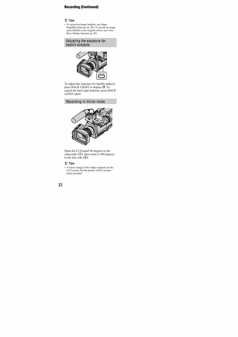
7/18/2019 SONY+HVR-HD1000 SERVICE MANUAL
http://slidepdf.com/reader/full/sonyhvr-hd1000-service-manual 313/42516
Connecting to a computer ............ 77
Copying still images to a computer.................................................... 77
Copying movies on a tape to acomputer .................................... 80
Troubleshooting ........................... 83
Warning indicators and messages.................................................... 91
Self-diagnosis display/Warning
indicators .................................. 91
Using your camcorder abroad ...... 94
Maintenance and precautions ...... 95Usable cassette tapes ................ 95About the “Memory Stick” ........... 96About the “InfoLITHIUM” battery
pack .......................................... 98About i.LINK ................................ 99About x.v.Color .......................... 100On using your camcorder ......... 100
Specifications ............................. 104
Identifying parts and controls ..... 107
Indicators displayed during recording/ playback ................................... 110
Index .......................................... 114
Using a Computer
Troubleshooting
Additional Information
Quick Reference
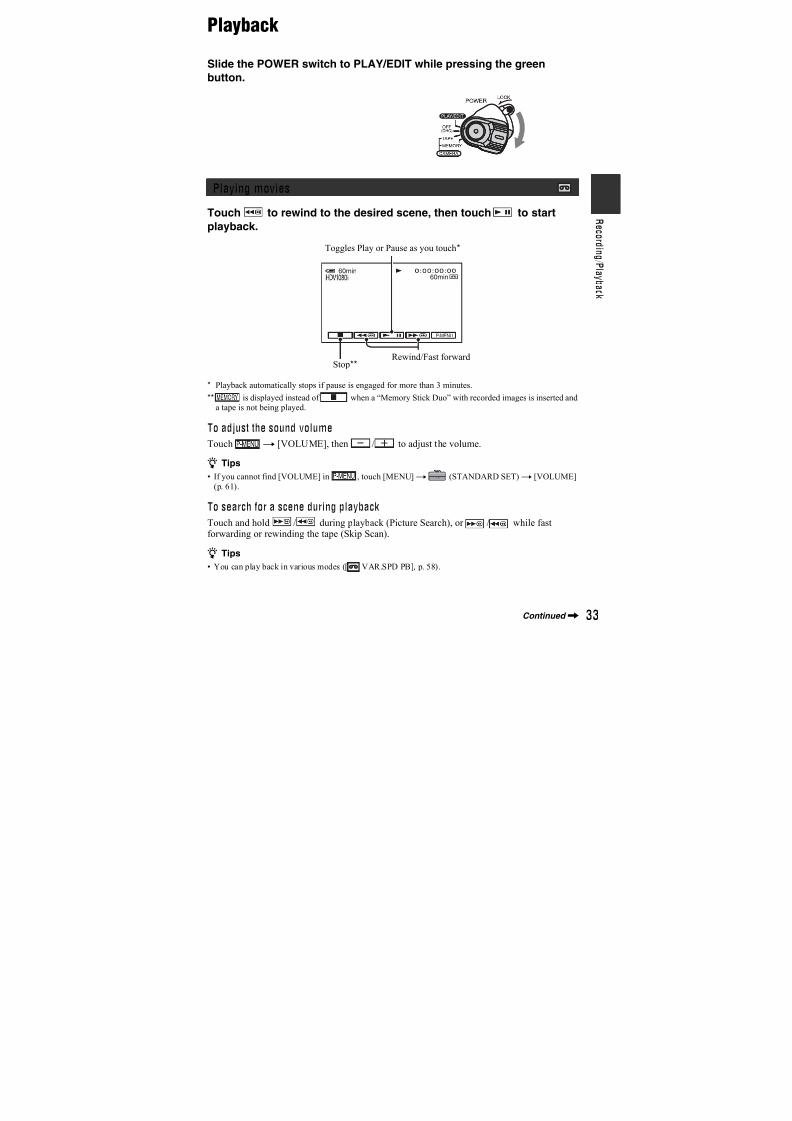
7/18/2019 SONY+HVR-HD1000 SERVICE MANUAL
http://slidepdf.com/reader/full/sonyhvr-hd1000-service-manual 314/42517
Using the CD-ROM Manual
The supplied CD-ROM includes versionsof the Operating Guide for the HVR-HD1000E/HD1000P series in English,French, German, Italian, Spanish, and
Simplified Chinese in PDF format.
The following program must be installed onyour computer in order to read theOperating Guide contained on the CD-ROM.
• Adobe Reader Version 7.0 or higher
z Tips
• If Adobe Reader is not installed, you candownload it from the following URL:http://www.adobe.com/
Adobe and Adobe Reader are trademarks of
Adobe Systems Incorporated in the United States
and/or other countries.
To read the Operating Guide contained onthe CD-ROM, do the following.
1 Insert the CD-ROM in your CD-
ROM drive.
A cover page appears automatically inyour browser.
If it does not appear automatically in the
browser, double-click on the index.htmfile on the CD-ROM.
2 Select and click on the Operating
Guide that you want to read.
This opens the PDF file of the OperatingGuide.
z Tips
• The files may not be displayed properly,depending on the version of AcrobatReader. In such a case, install the latest
version you can download from the URLmentioned in “Preparation” above.
Preparation
Reading the CD-ROM Manual
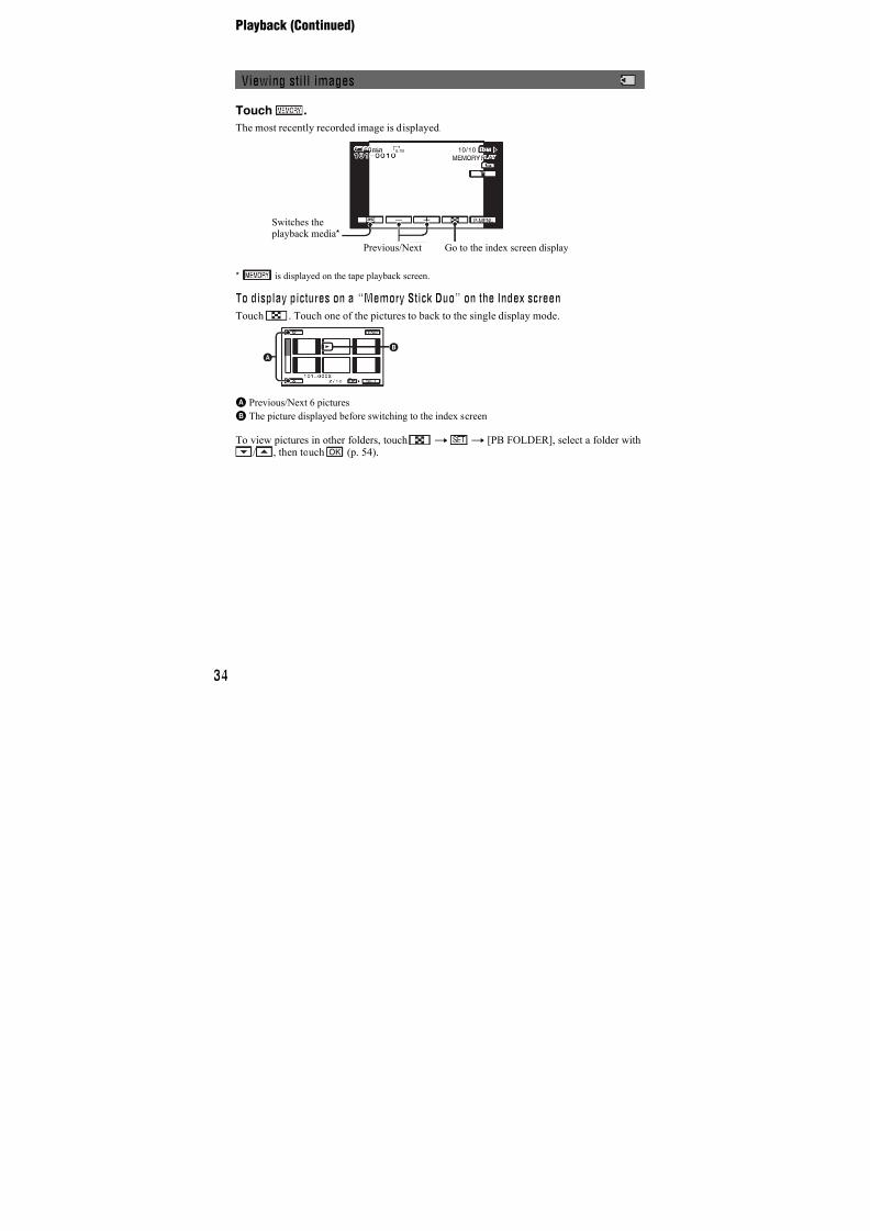
7/18/2019 SONY+HVR-HD1000 SERVICE MANUAL
http://slidepdf.com/reader/full/sonyhvr-hd1000-service-manual 315/42518
Getting Started
Step 1: Checking supplied items
Make sure that you have following itemssupplied with your camcorder.The number in the parentheses indicates thenumber of that item supplied.
AC Adaptor (1) (p. 21)
Power cord (mains lead) (1) (p. 21)
A/V connecting cable (1) (p. 37, 68)
Eye cup (1)
Rechargeable battery pack NP-F570 (1)(p. 21, 98)
Lens hood (1)
Lens cap (1)
Wind screen (1) (p. 19)Microphone (1) (p. 19)
CD-ROM “Manuals for Digital HD Video CameraRecorder”(1)
Operating Guide (This manual) (1)
To attach the lens cap to the grip belt
Remove the grip belt and attach the lens
cap by leading the grip belt through theattachment on the lens cap string. Thenattach the grip belt to the camcorder again.
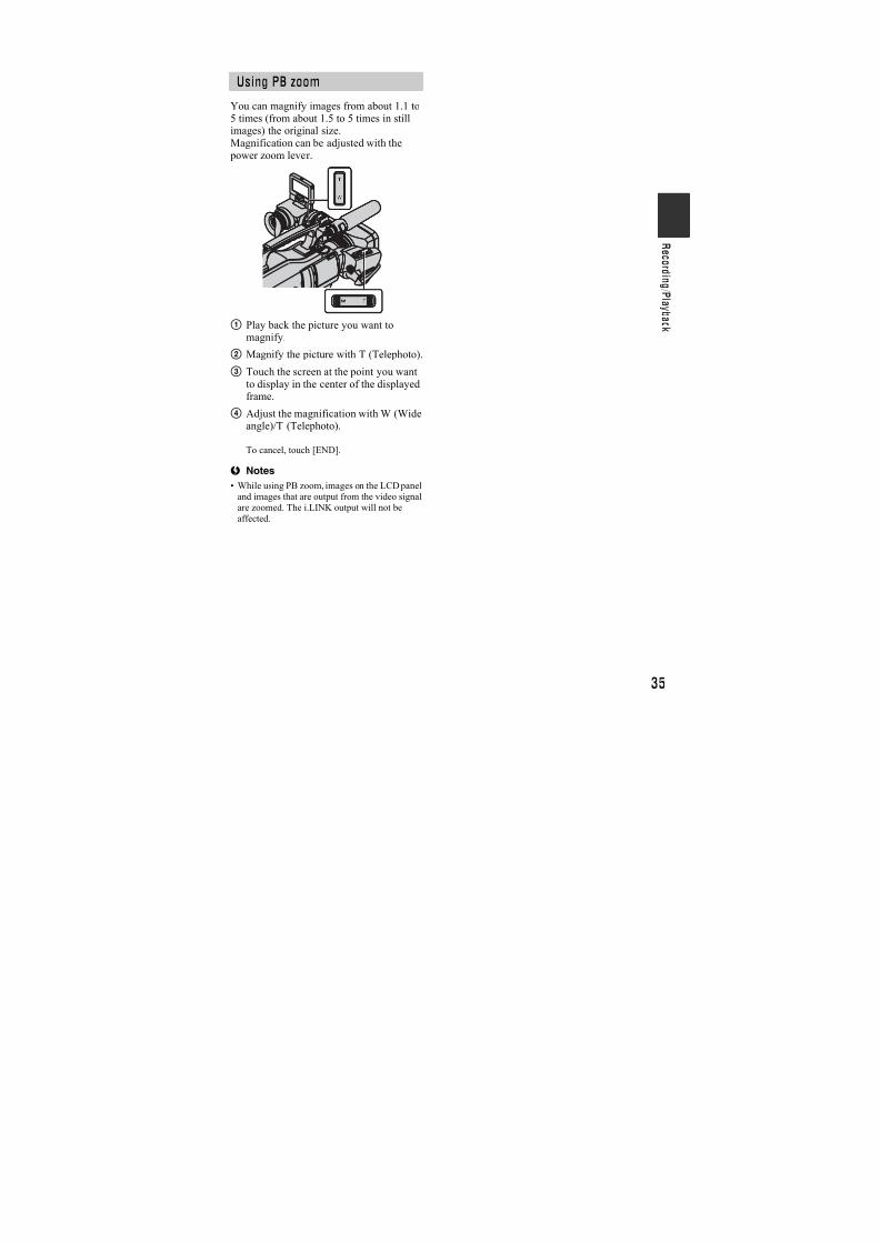
7/18/2019 SONY+HVR-HD1000 SERVICE MANUAL
http://slidepdf.com/reader/full/sonyhvr-hd1000-service-manual 316/42519
G e t t i n g S t a r t e
d
Step 2: Attaching the supplied microphone,eyecup and the lens hood
1 Attach the wind screen1 to the
microphone2.
2 Unlock the stopper of the
microphone holder3 and open
the cover.
3 Align the convex part of the
microphone with the concave part
of the holder, then place the
microphone into the holder. Close
the cover and lock the stopper
securely.
Be sure to align the v mark on the
microphone and the | mark on the
holder facing each other.
4 Turn the plug of the microphone
counter-clockwise to 180 degrees
in the direction of the arrow5,and connect it to the Mic jack4.
Attach the eyecup aligned with the eyecupgroove in the viewfinder. You can attachthe eyecup facing either the right or leftside.
Attaching the suppliedmicrophone
1
2
3
4
5
Attaching the eyecup
Attach theeyecup securelyuntil it fits thecorrespondingpart properly.
Continued,
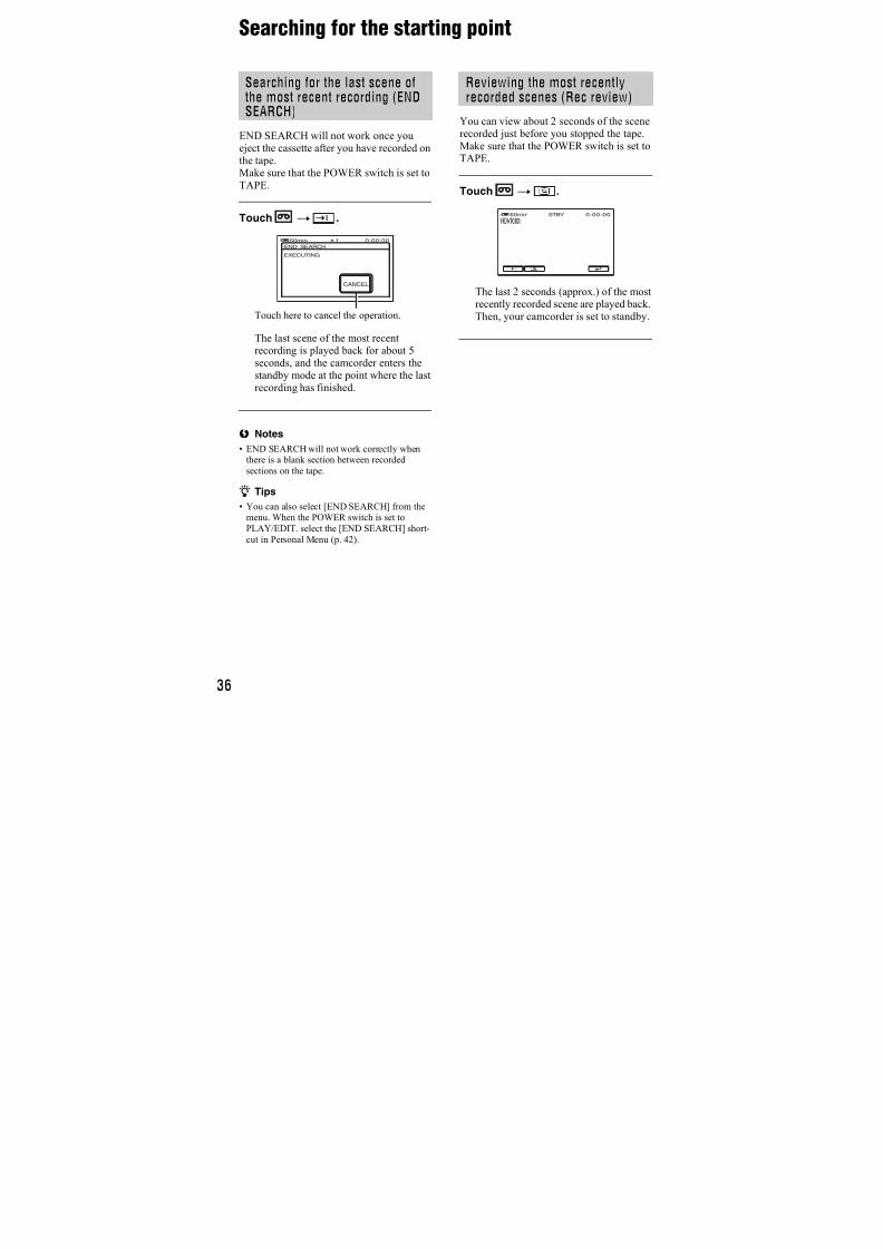
7/18/2019 SONY+HVR-HD1000 SERVICE MANUAL
http://slidepdf.com/reader/full/sonyhvr-hd1000-service-manual 317/42520
Align the marks on the lens hood to
those on the camcorder, and turn the
lens hood in the direction of the
arrow.
To remove the Lens hood
Turn the lens hood cover in the opposite
direction of the arrow as illustrated above while pressing the lever on the lens hood cover.
z Tips
• If you attach, remove or adjust an 37mm(2 1/2in.) PL filter or MC protector, remove the
lens hood.
Attaching the lens cap
Attach the lens cap by pressing both knobson its sides.
Attaching the lens hood
1 2
1
2
Step 2: Attaching the supplied microphone and the lens hood (Continued)
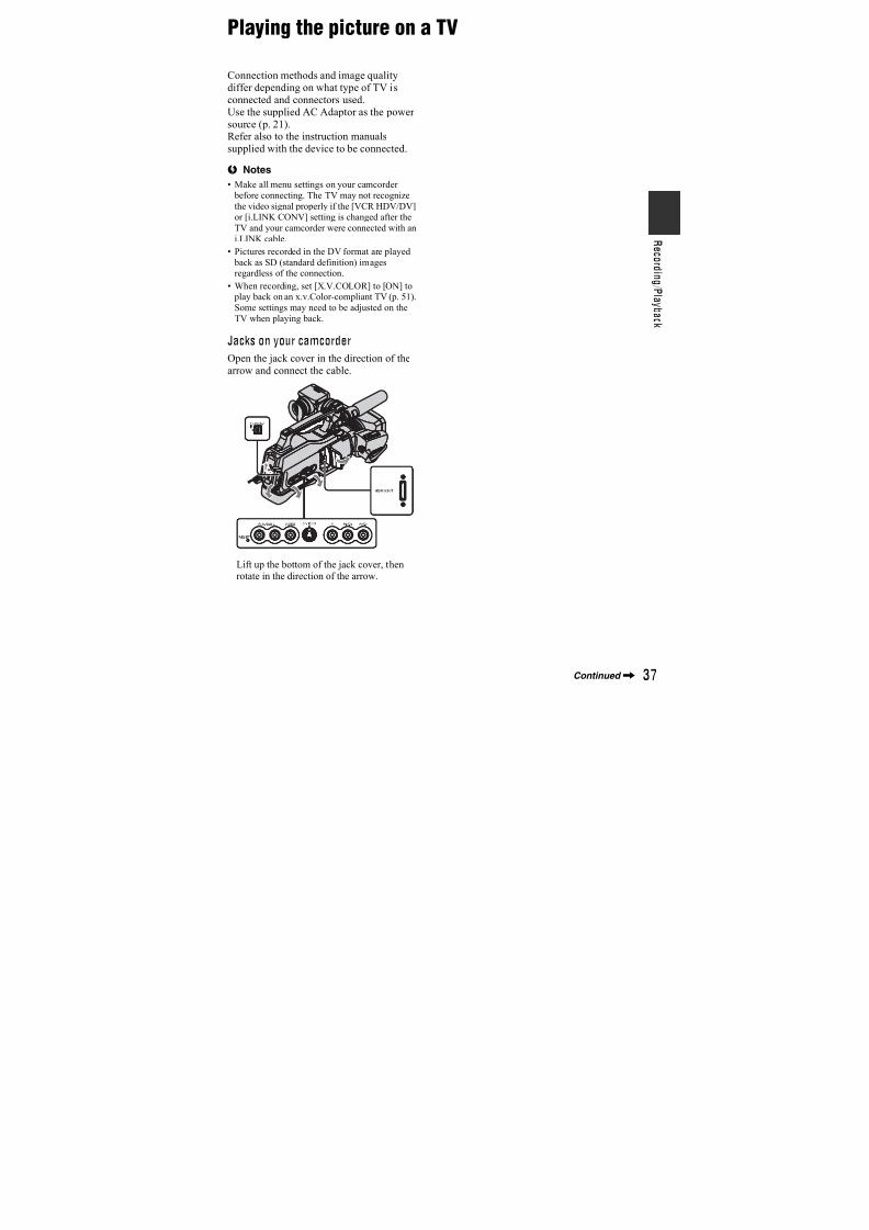
7/18/2019 SONY+HVR-HD1000 SERVICE MANUAL
http://slidepdf.com/reader/full/sonyhvr-hd1000-service-manual 318/42521
G e t t i n g S t a r t e
d
Step 3: Charging the battery pack
You can charge the “InfoLITHIUM”
battery pack (L series) (p. 98) after
attaching it to your camcorder.
b Notes
• You cannot attach any “InfoLITHIUM” battery
pack other than the L series to your camcorder.
1 Attach the battery pack to your
camcorder.Attach the battery pack by sliding it inthe direction of the arrow while pressingit until it clicks.
2 Slide the POWER switch to OFF
(CHG).
3 Connect the AC Adaptor to the
DC IN jack of your camcorder. Be
sure that the v mark on the DC
plug is facing to the v mark on
your camcorder.
4 Connect the power cord (mains
lead) to the AC Adaptor and the
wall outlet (wall socket).
The CHG (charge) lamp lights up andcharging starts. The CHG (charge) lampturns off when the battery is fullycharged.
b Notes
• Disconnect the AC Adaptor from the DC IN
jack holding both the camcorder and the DC
plug.
z Tips
• You can operate your camcorder connected to a power source such as a wall outlet (wall socket)
as shown in the illustration. The battery pack
will not lose its charge in this case.
4
3
2
1
Battery pack
To the wall outlet(wall socket)
Power cord(Mains lead)
AC Adaptor
POWERswitch
DC plug
DC IN jack
CHG(charge)lamp
Continued,
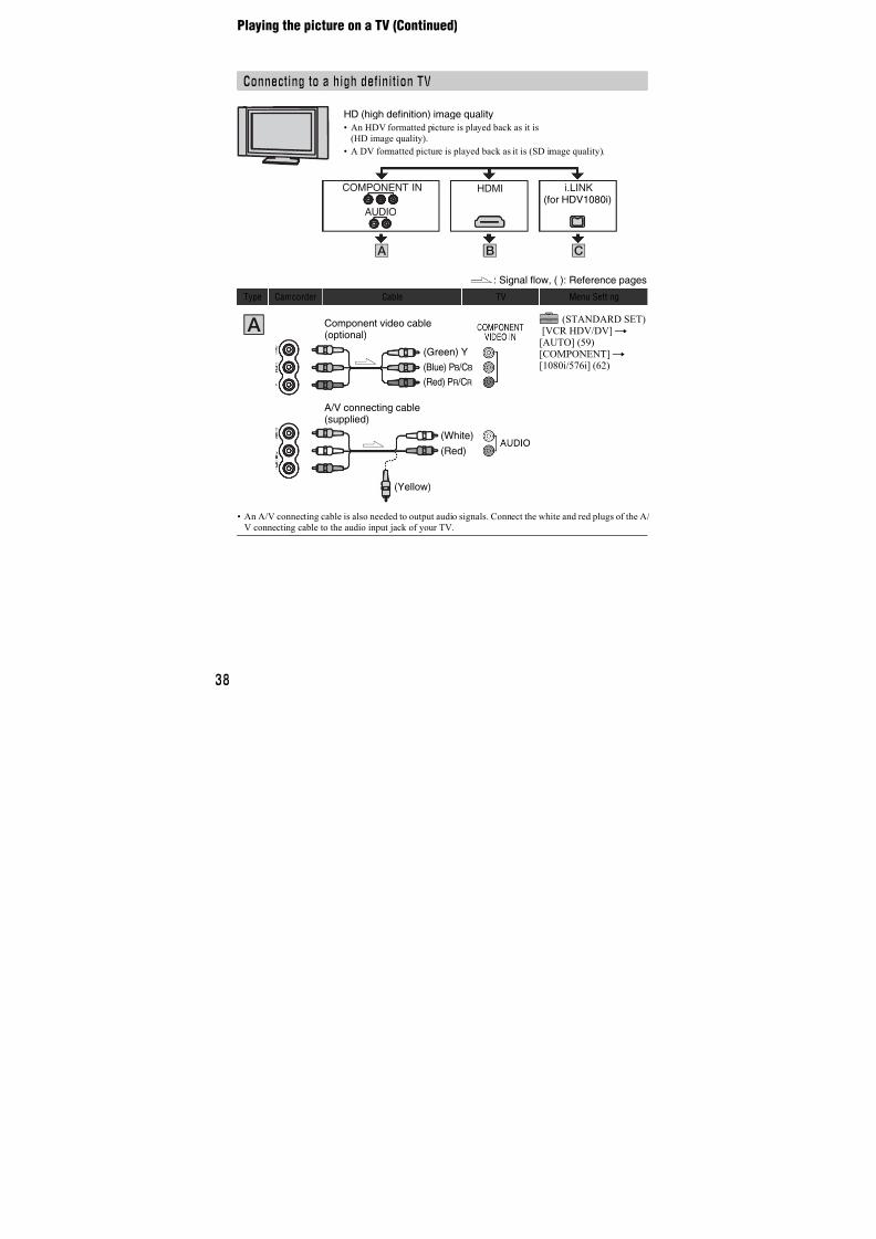
7/18/2019 SONY+HVR-HD1000 SERVICE MANUAL
http://slidepdf.com/reader/full/sonyhvr-hd1000-service-manual 319/42522
To remove the battery pack
Slide the POWER switch to OFF (CHG).Push the [BATT (battery) RELEASE]
button and remove the battery pack.
When storing the battery pack
Fully discharge the battery before storing itfor an extended period (p. 98).
To check the remaining battery
(Battery Info)Set the POWER switch to OFF (CHG), then
press DISPLAY/BATT INFO.
After a while, the approximate recordabletime and battery information appear forabout 7 seconds. You can view the batteryinformation for up to 20 seconds by
pressing DISPLAY/BATT INFO againwhile the information is displayed.
You can check the remaining battery chargeon the LCD screen.
Charging time
Approximate time (min.) required whenyou fully charge a fully discharged battery
pack.
Recording timeApproximate time (min.) available whenyou use a fully charged battery pack.
[BATT (battery)RELEASE]
Indicator StatusSufficient power remaining
Battery low, recording/
playback will stop soon.
Replace the battery with a
fully charged one, or charge
the battery.
Battery pack Charging time
NP-F570 (supplied) 260
NP-F770 450
NP-F970 630
Battery packContinuousrecordingtime
Typicalrecordingtime*
RecordingFormat
HDV DV HDV DV
NP-F570
(supplied)
190 200 100 110
205 220 110 125
NP-F770 390 410 210 230
425 445 225 250
60
65
Remaining battery (approx.)
Recording capacity (approx.)
Step 3: Charging the battery pack (Continued)
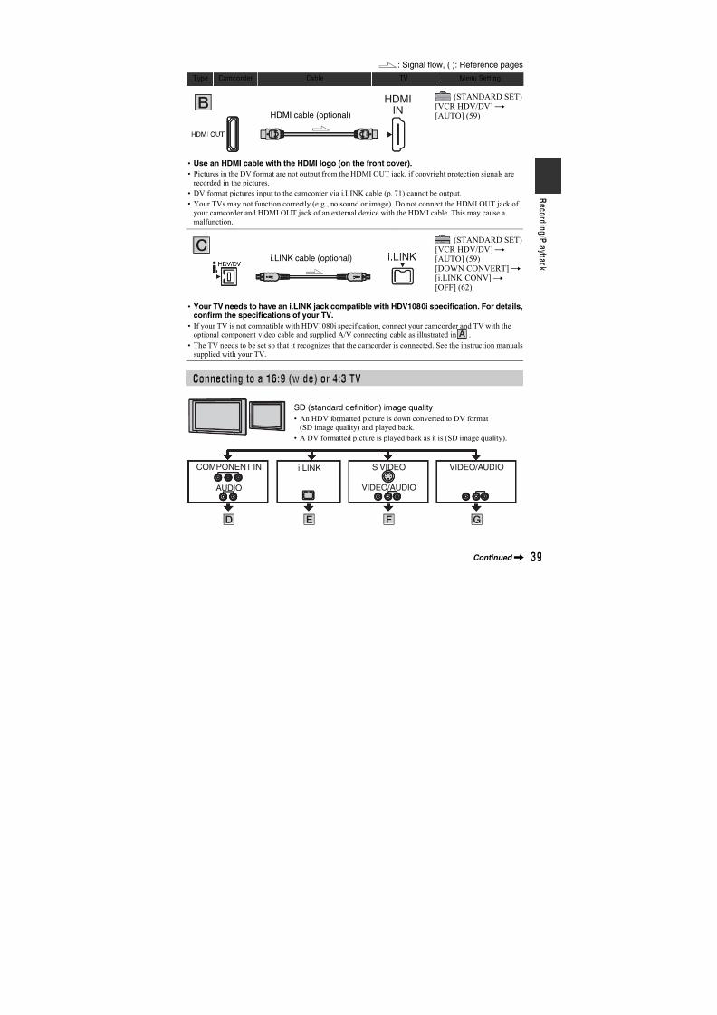
7/18/2019 SONY+HVR-HD1000 SERVICE MANUAL
http://slidepdf.com/reader/full/sonyhvr-hd1000-service-manual 320/42523
G e t t i n g S t a r t e
d
* Typical recording time shows the time when
you repeat recording start/stop, turning the
power on/off and zooming.
b Notes
• All times measured under the following
conditions:Top: When the LCD turns on.
Bottom: Recording with the viewfinder while
the LCD turns off.
• You cannot turn off the viewfinder.
Playing time
Approximate time (min.) available whenyou use a fully charged battery pack.
On the battery pack • Before changing the battery pack, slide the
POWER switch to OFF (CHG).
• The CHG (charge) lamp flashes during
charging, or Battery Info (p. 22) will not becorrectly displayed under the following
conditions.
– The battery pack is not attached correctly.
– The battery pack is damaged.
– The battery pack is worn-out (for Battery Info
only).
• The power will not be supplied from the battery
as long as the AC Adaptor is connected to theDC IN jack of your camcorder, even when the
power cord (mains lead) is disconnected from
the wall outlet (wall socket).
On the charging/recording/playback time
• Times measured with the camcorder at 25 °C(77 °F) (10 to 30 °C (50 °F to 86 °F) is
recommended).
• The recording and playback time will be shorter
when you use your camcorder in low
temperatures.
• The recording and playback time will be shorter
depending on the conditions under which youuse your camcorder.
On the AC Adaptor
• Use the nearby wall outlet when using the AC
Adaptor. Disconnect the AC Adaptor from the
wall outlet immediately if any malfunction
occurs while using your camcorder.
• Do not use the AC Adaptor placed in a narrow
space, such as between a wall and furniture.
• Do not short-circuit the DC plug of the AC
Adaptor or battery terminal with any metallicobjects. This may cause a malfunction.
• Even if your camcorder is turned off, AC power
(house current) is still supplied to it whileconnected to the wall outlet via the AC Adaptor.
NP-F970 580 605 310 340
630 660 340 375
Battery pack LCD panelon
LCD paneloff
RecordedFormat
HDV DV HDV DV
NP-F570
(supplied)
260 280 295 315
NP-F770 540 570 605 650
NP-F970 780 830 890 950
Battery packContinuousrecordingtime
Typicalrecordingtime*
Recording
Format HDV DV HDV DV
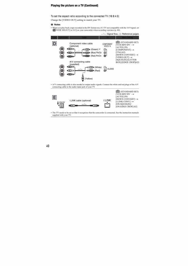
7/18/2019 SONY+HVR-HD1000 SERVICE MANUAL
http://slidepdf.com/reader/full/sonyhvr-hd1000-service-manual 321/42524
Step 4: Turning the power on and setting thedate and timeSet the date and time when using thiscamcorder for the first time. If you do notset the date and time, the [CLOCK SET]screen appears every time you turn on your
camcorder or change the POWER switch position.
1 Slide the POWER switch to TAPE
or MEMORY while pressing the
green button.
TAPE: To record on a tape.
MEMORY: To record on a “MemoryStick Duo.”PLAY/EDIT: To play or edit pictures.
The [CLOCK SET] screen appears.
2 Set [Y] (year) with / , then
touch .
You can set any year up to the year2079.
3 Set [M] (month), then touch
and repeat for [D] (day), hour and
minute.
The clock starts.
To turn off the power
Slide the POWER switch to OFF (CHG).
To reset the date and time
You can set the desired date and time bytouching t [MENU]t
(TIME/LANGU.) t [CLOCK SET](p. 42).
b Notes
• If you do not use your camcorder for about 3months, the built-in rechargeable battery gets
discharged and the date and time settings may
be cleared from the memory. In that case,
charge the rechargeable battery and then set the
date and time again (p. 103).
z Tips
• The date and time are not displayed while
recording, but they are automatically recordedon the tape, and can be displayed during
playback (see page 64 for [DATA CODE]).
• If the buttons on the touch panel do not work
correctly, adjust the touch panel(CALIBRATION) (p. 102).
You can change the on-screen displays to
show messages in a specified language.Touch t [MENU]t (TIME/LANGU.) t [LANGUAGE], then selectthe desired language.
POWER switch
Touch the button onthe LCD screen.
OK
CLOCK SET
DATE2007 Y 1M 1D 0: 00
Changing the language setting
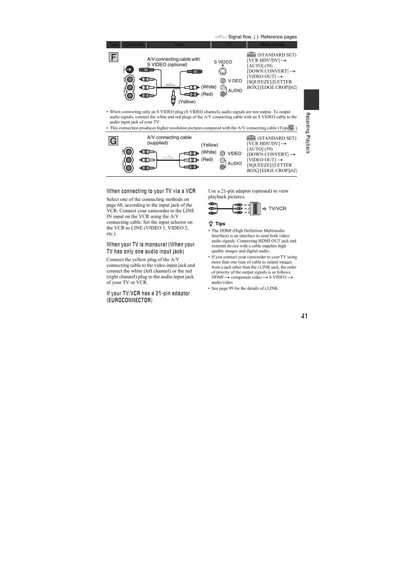
7/18/2019 SONY+HVR-HD1000 SERVICE MANUAL
http://slidepdf.com/reader/full/sonyhvr-hd1000-service-manual 322/42525
G e t t i n g S t a r t e
d
Step 5: Making setting adjustments beforerecording
Open the LCD panel (1), then rotate it to
the best angle to record or play (2).
To turn off the LCD screenSet the LCD ON/OFF switch to OFF. Thishelps to make the battery last longer. Therecorded picture will not be affected by thesetting. To turn on the LCD screen, set theLCD ON/OFF switch to ON.
b Notes
• When the LCD ON/OFF switch is set to OFF,
you cannot operate the touch panel.
z Tips
• If you rotate the LCD panel 180 degrees to the
lens side, you can close the LCD panel with the
LCD screen facing out. This is convenientduring playback operations.
• See [LCD/VF SET] - [LCD BRIGHT] (p. 61) toadjust the brightness of the LCD screen.
• Press DISPLAY/BATT INFO to toggle thescreen indicators (such as Battery Info) on or
off.
Pull out the LCD panel block to adjust the
position (1), and rotate the viewfinder tothe best angle (2).You can view pictures using the viewfinderto avoid wearing down the battery, or whenthe picture seen on the LCD screen is poor.
z Tips
• You can adjust the brightness of the viewfinder
backlight by selecting [LCD/VF SET] - [VF
B.LIGHT] (p. 61).
You can adjust the position of the shoulder pad by loosen the screws illustrated below.Tighten the screws again after adjustment.
The LCD panel
180 degrees(max.)
180 degrees(max.)
1
2
90 degrees(max.)
The viewfinder
The shoulder pad
Viewfinder lensadjustment leverMove it until the picture is clear.
1
2
Screws
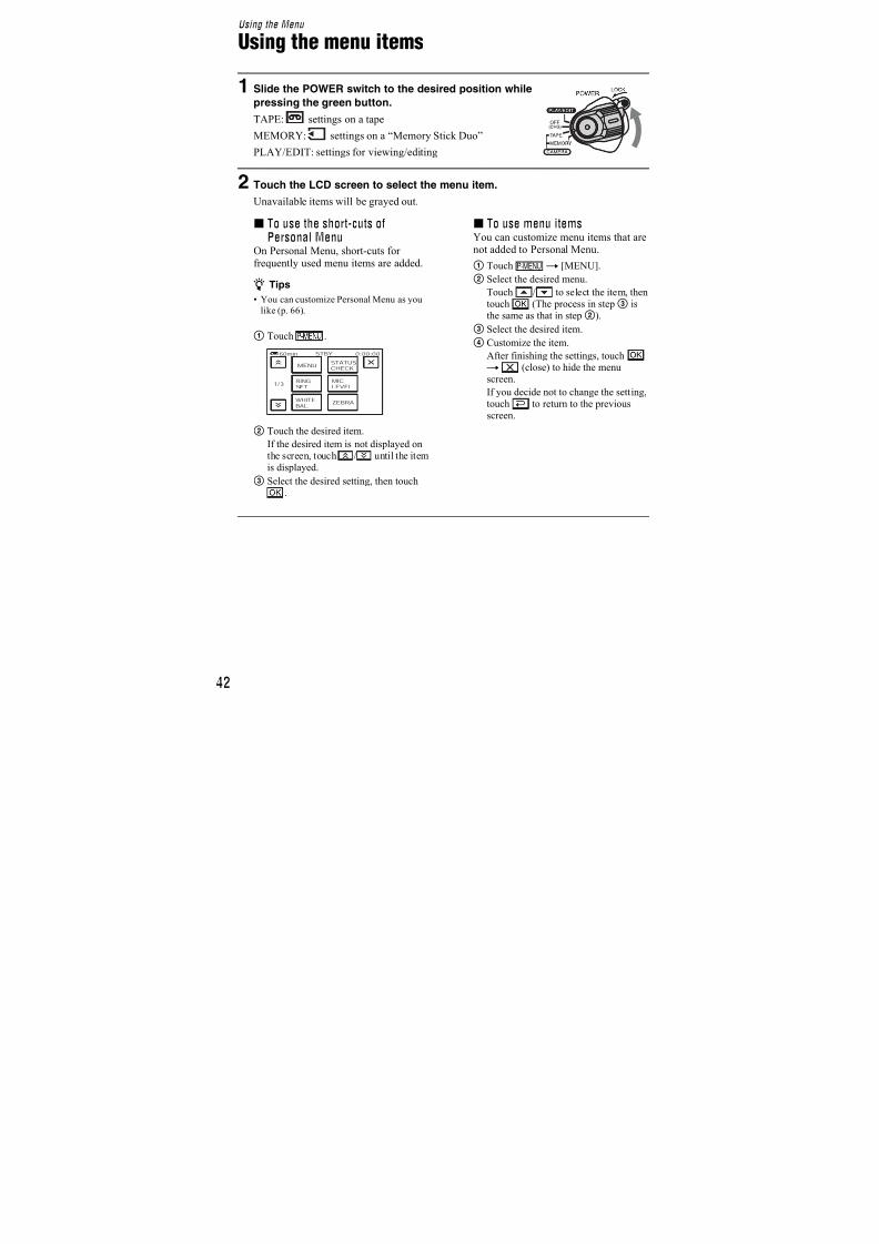
7/18/2019 SONY+HVR-HD1000 SERVICE MANUAL
http://slidepdf.com/reader/full/sonyhvr-hd1000-service-manual 323/42526
Step 6: Inserting a tape or a “Memory StickDuo”
You can use mini DV cassettes only
(p. 95).b Notes
• The recordable time varies depending on [REC MODE] (p. 60).
1 Slide and hold the OPEN/
EJECT lever in the direction of the
arrow and open the lid.
The cassette compartment automaticallycomes out and opens up.
2 Insert a cassette with its window
facing outwards, then press
.
The cassette compartmentautomatically slides back in.
3 Close the lid.
To eject the cassetteOpen the lid following the same procedureas described in step 1 and remove thecassette.
b Notes
• Do not force the cassette compartmentclosed by pressing the portion marked
while it is sliding in. Itmay cause a malfunction.
You can use only a “Memory Stick Duo”marked with or
(p. 96).
z Tips
• The number and time of recordable pictures
vary depending on the image quality or the
image size. For details, see page 52.
Cassette tape
OPEN/EJECT lever
Lid
“Memory Stick Duo”
Window
Push the center of the backof the cassette lightly.
Cassette
compartment
DONOTPUSH
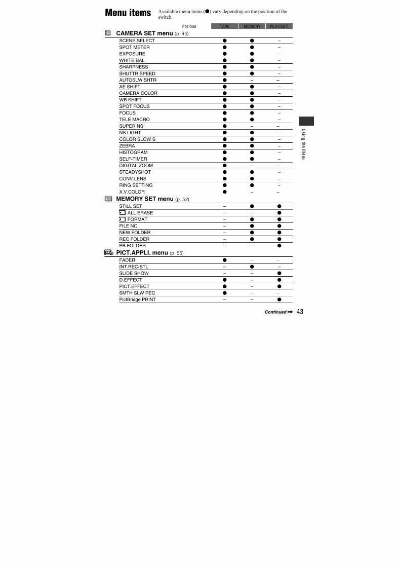
7/18/2019 SONY+HVR-HD1000 SERVICE MANUAL
http://slidepdf.com/reader/full/sonyhvr-hd1000-service-manual 324/42527
G e t t i n g S t a r t e
d
1 Open the jack cover.
2 Insert the “Memory Stick Duo”
into the “Memory Stick Duo” slot
in the right direction until it clicks.
To eject a “Memory Stick Duo”
Lightly push the “Memory Stick Duo” inonce.
b Notes
• When the access lamp is lit or flashing, yourcamcorder is reading/writing data. Do not shake
or knock your camcorder, turn the power off,
eject the “Memory Stick Duo,” or remove the
battery pack. Otherwise, image data may bedamaged.
• If you force the “Memory Stick Duo” into the
slot in the wrong direction, the “Memory Stick
Duo,” the “Memory Stick Duo” slot, or imagedata may be damaged.
• When inserting or ejecting the “Memory StickDuo,” be careful that the “Memory Stick Duo”
does not pop out and drop.
Accesslamp
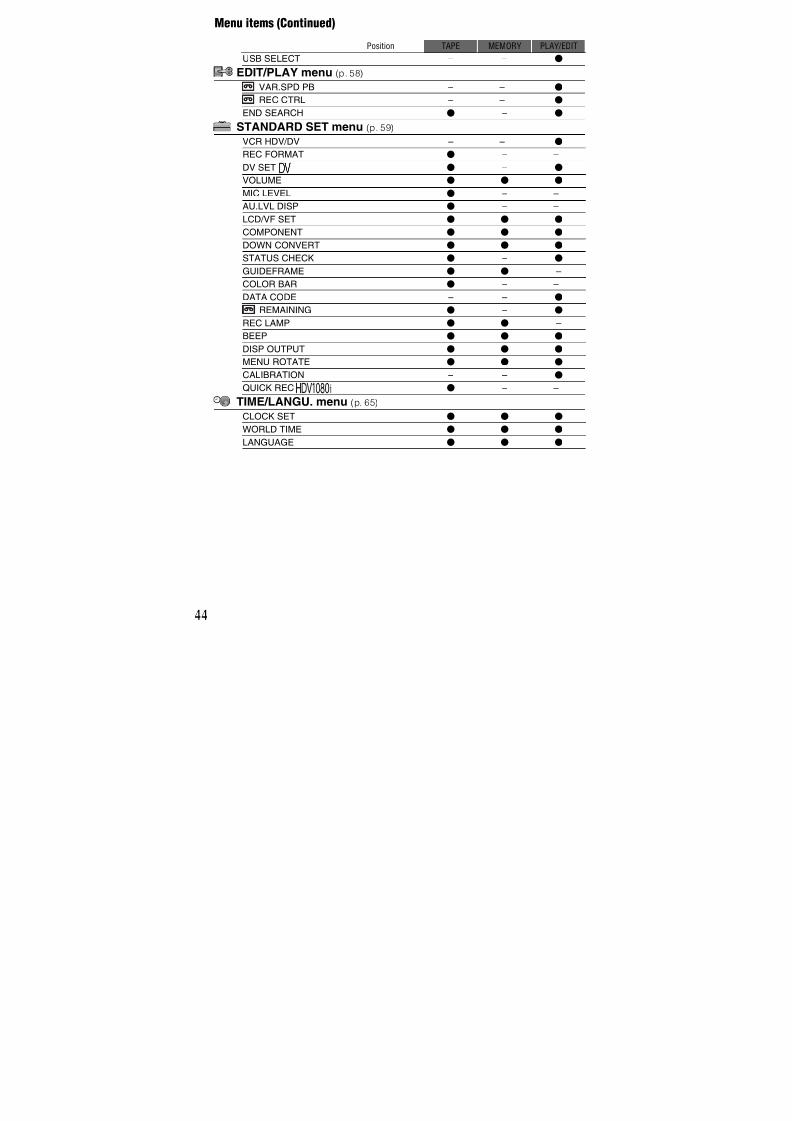
7/18/2019 SONY+HVR-HD1000 SERVICE MANUAL
http://slidepdf.com/reader/full/sonyhvr-hd1000-service-manual 325/42528
Recording/Playback
Recording
Movies are recorded on a tape.
Remove the lens cap by pressing both knobs on its sides.
Slide the POWER switch to TAPE while pressing the green
button.
Press START/STOPA (orB).
To stop recording, press START/STOP again.z Tips
• The pictures are recorded in the HDV format in the default setting (p. 60).
Recording movies
PHOTO
START/STOPB
START/STOPA
Note on the LOCK switch
When you slide the LOCK switch to the lock position (the POWER switch side), the POWERswitch can no longer be set to MEMORYaccidentally. (The LOCK switch is set to theunlock position at the time of purchase.)
LOCKswitch
LOCK UNLOCK
60min60min
60min60min
STBY REC
P-MENU P-MENU
[STBY] [REC]
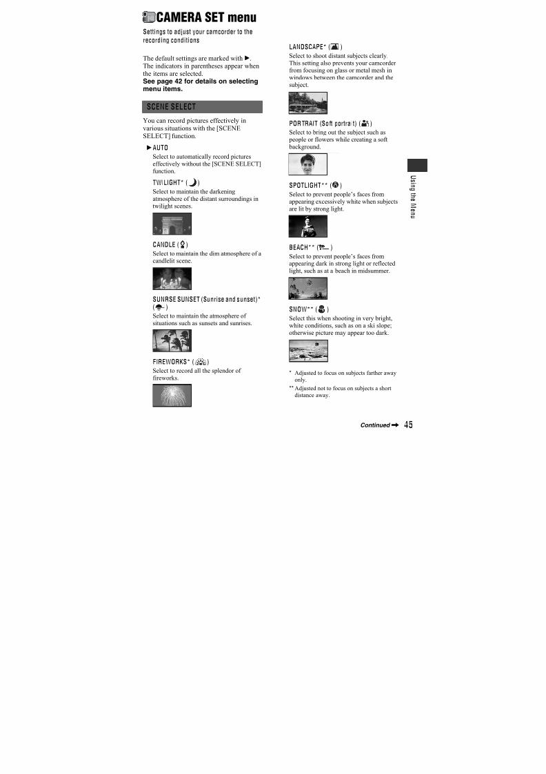
7/18/2019 SONY+HVR-HD1000 SERVICE MANUAL
http://slidepdf.com/reader/full/sonyhvr-hd1000-service-manual 326/42529
R e c o r d i n g / P l a y b a c k
To record high quality still images during tape recording (Dual Rec)
See page 30 for details.
Still images are recorded on the “Memory Stick Duo.”
Remove the lens cap by pressing both knobs on its sides.
Slide the POWER switch to MEMORY while pressing the green
button.
Press and hold PHOTO lightly to adjust the focus, then press itfully to record.
A shutter sound is heard. When disappears, the image has been recorded.
To check the latest recording on a “Memory Stick Duo”
Touch . To delete the picture, touch t [YES].
z Tips
• See page 52 for the image quality, image size and the number of recordable pictures.
Recording still images
6.1M 6.1M
P-MENU P-MENU
min minBeep Shutter click
Flashing bLights up
Continued,
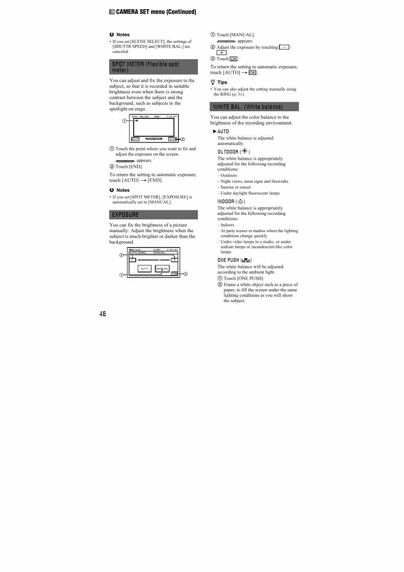
7/18/2019 SONY+HVR-HD1000 SERVICE MANUAL
http://slidepdf.com/reader/full/sonyhvr-hd1000-service-manual 327/42530
You can magnify images to 10 times theoriginal size with the power zoom lever.
Move the power zoom leverB slightly fora slower zoom. Move it further for a fasterzoom.
b Notes
• Be sure to keep your finger on the power zoom
lever. If you move your finger off the powerzoom lever, the operation sound of the power
zoom lever may also be recorded.
• You can not change the zoom speed of the zoom
leverA on the handdle.
• The minimum possible distance between
camcorder and subject while maintaining sharp
focus is about 1 cm (about 13/32 in.) for wideangle and about 80 cm (about 2 5/8 feet) for
telephoto.
z Tips
• You can set [DIGITAL ZOOM] (p. 50) if you
want to zoom to a level greater than 10 ×.
• You can also adjust the setting manually using
the RING (p. 31).
You can record high quality still images onthe “Memory Stick Duo” during taperecording.
1 Slide the POWER switch to TAPE, then press START/STOP to start tape recording.
2 Press PHOTO fully.For each separate time tape recording, up to3 still images can be recorded.
3 Press START/STOP to stop tape recording.
Stored still images appear one by one, andthe images are stored onto the “MemoryStick Duo.” When disappears, theimage has been recorded.
b Notes
• Do not eject the “Memory Stick Duo” before
tape recording is finished and the still imagesare stored on the “Memory Stick Duo.”
Zooming
Power zoom lever
A
B
Close view: (Telephoto)
Wider range of view: (Wide angle)
Recording high quality stillimages during tape recording(Dual Rec)
Orange color boxes indicatethe number ofrecordedimages. Whenrecording isfinished, the
color changesto orange.
Recording (Continued)

7/18/2019 SONY+HVR-HD1000 SERVICE MANUAL
http://slidepdf.com/reader/full/sonyhvr-hd1000-service-manual 328/42531
R e c o r d i n g / P l a y b a c k
z Tips
• During the standby mode, still images will bestored in the same way as when the POWER
switch is set to MEMORY.
• When the POWER switch is set to TAPE, stillimages will be recorded at image size 4.6M in
the HDV format, 3.4M (4:3) or 4.6M (16:9) in
the DV format.
It is useful to assign a frequently used menuitem to the RING.
The following is an example of the procedure when the [FOCUS] setting isassigned (the default setting).
1 Press the MANUAL button to activate themanual adjustment mode.
The setting mode switches betweenautomatic and manual every time you pressthe MANUAL button.
2 Rotate the RING to adjust the focusmanually.
Menu items that can be assigned
– [FOCUS] (p. 48)
– [ZOOM] (p. 30)
– [EXPOSURE] (p. 46)
– [SHUTTR SPEED] (p. 47)
– [AE SHIFT] (p. 47)
– [WB SHIFT] (p. 48)
To assign the menu items to the RING1 Press and hold the MANUAL button for
several seconds.
The [RING SETTING] screen appears.
2 Rotate the RING and select a menu item to be assigned.
3 Press the MANUAL button.
b Notes
• The menu item settings done before will beretained even if you set other menu item settings
after that. If [EXPOSURE] is set after [AE
SHIFT] is set manually, [EXPOSURE] willoverride [AE SHIFT].
• If you select [RESET] in step2, all the settings
set manually return to the default setting.
z Tips
• During playback, you can adjust the volume
using the RING.
• You can also assign menu items using [RING
SETTING] (p. 51).
Set the NIGHTSHOT switch to ON (and [“NIGHTSHOT”] appear).
b Notes
• The NightShot and Super NightShot functions
use infrared light. Therefore, do not cover the
infrared port with your fingers or other objects
and remove the conversion lens (optional).• Adjust the focus manually ([FOCUS], p. 48)
when it is hard to focus automatically.
• Do not use these functions in bright places. Thismay cause a malfunction.
Controlling the image settingsmanually with the RING
RINGMANUAL button Recording in dark places
(NightShot)
0:00:0060min
RING SETTING
FOCUSZOOMEXPOSURESHUTTR SPEEDAE SHIFT
WB SHIFTRESET
STBY
[MANUAL]:EXEC
Infrared port
Continued,
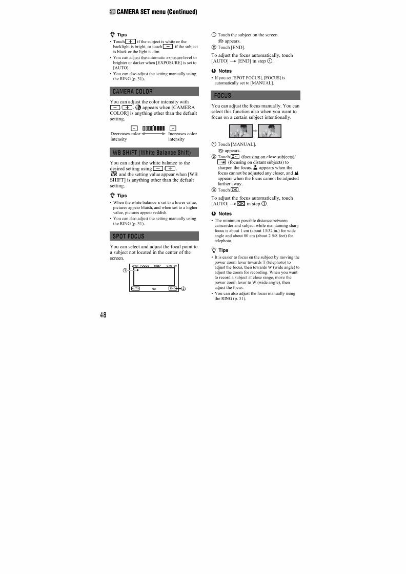
7/18/2019 SONY+HVR-HD1000 SERVICE MANUAL
http://slidepdf.com/reader/full/sonyhvr-hd1000-service-manual 329/42532
z Tips
• To record an image brighter, use Super NightShot function (p. 49). To record an image
more faithful to the original colors, use Color
Slow Shutter function (p. 49).
To adjust the exposure for backlit subjects, press BACK LIGHT to display.. Tocancel the back light function, press BACKLIGHT again.
Open the LCD panel 90 degrees to thecamcorder (1), then rotate it 180 degreesto the lens side (2).
z Tips
• A mirror-image of the subject appears on theLCD screen, but the picture will be normal
when recorded.
Adjusting the exposure forbacklit subjects
Recording in mirror mode
Recording (Continued)
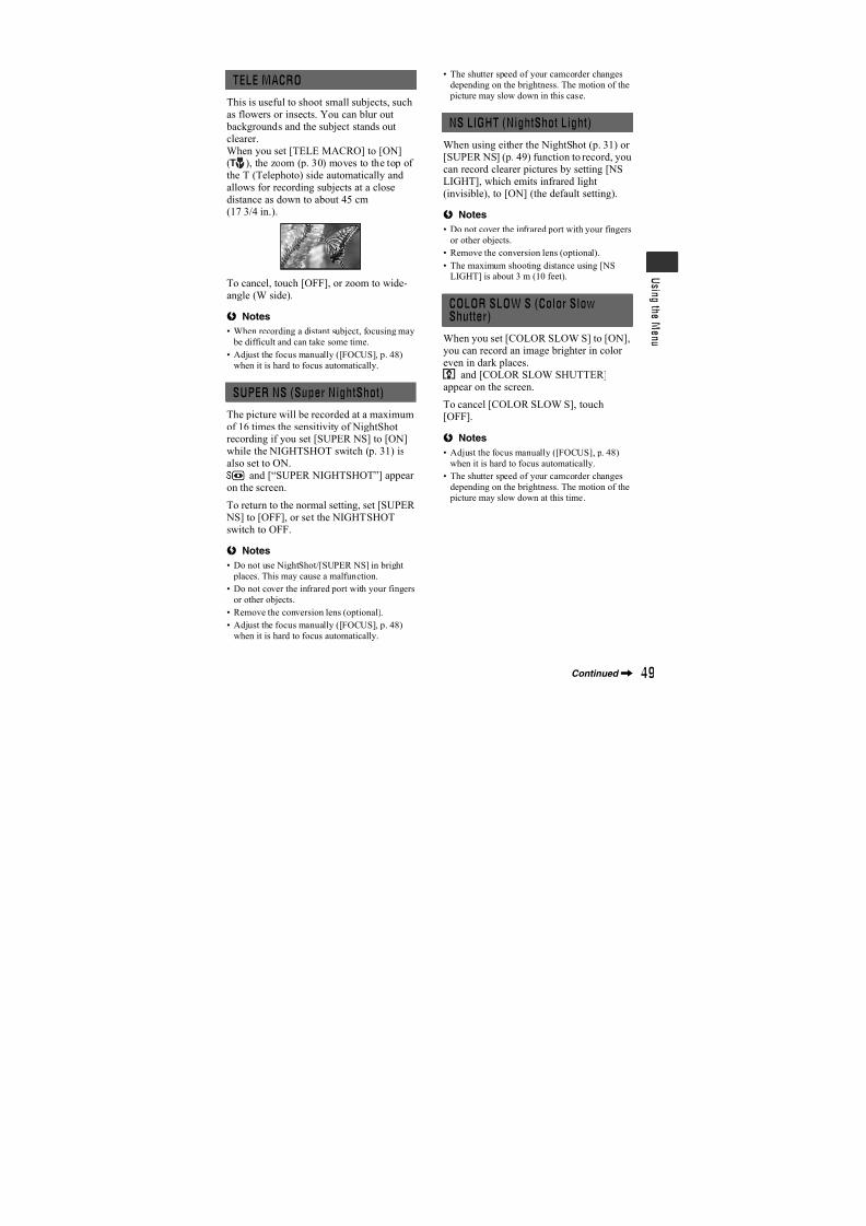
7/18/2019 SONY+HVR-HD1000 SERVICE MANUAL
http://slidepdf.com/reader/full/sonyhvr-hd1000-service-manual 330/42533
R e c o r d i n g / P l a y b a c k
Playback
Slide the POWER switch to PLAY/EDIT while pressing the green
button.
Touch to rewind to the desired scene, then touch to start
playback.
To adjust the sound volume
Toucht
[VOLUME], then / to adjust the volume.
z Tips
• If you cannot find [VOLUME] in , touch [MENU]t (STANDARD SET)t [VOLUME]
(p. 61).
To search for a scene during playback
Touch and hold / during playback (Picture Search), or / while fastforwarding or rewinding the tape (Skip Scan).
z Tips
• You can play back in various modes ([ VAR.SPD PB], p. 58).
Playing movies
* Playback automatically stops if pause is engaged for more than 3 minutes.
** is displayed instead of when a “Memory Stick Duo” with recorded images is inserted anda tape is not being played.
P-MENU
60min60min
Toggles Play or Pause as you touch*
Stop**Rewind/Fast forward
Continued,
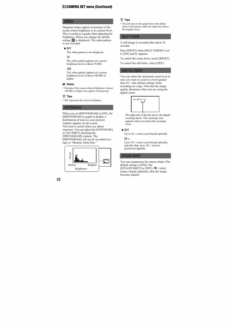
7/18/2019 SONY+HVR-HD1000 SERVICE MANUAL
http://slidepdf.com/reader/full/sonyhvr-hd1000-service-manual 331/42534
Touch .
The most recently recorded image is displayed.
* is displayed on the tape playback screen.
To display pictures on a “Memory Stick Duo” on the Index screen
Touch . Touch one of the pictures to back to the single display mode.
A Previous/Next 6 pictures
B The picture displayed before switching to the index screen
To view pictures in other folders, touch t t [PB FOLDER], select a folder with/ , then touch (p. 54).
Viewing still images
P-MENU
60 minin 6.1M60min 10/10MEMORY PLAYEMORY PLAYMEMORY PLAY
Previous/Next
Switches the playback media*
Go to the index screen display
AB
Playback (Continued)
7/18/2019 SONY+HVR-HD1000 SERVICE MANUAL
http://slidepdf.com/reader/full/sonyhvr-hd1000-service-manual 332/42535
R e c o r d i n g / P l a y b a c k
You can magnify images from about 1.1 to5 times (from about 1.5 to 5 times in stillimages) the original size.Magnification can be adjusted with the
power zoom lever.
1 Play back the picture you want tomagnify.
2 Magnify the picture with T (Telephoto).
3 Touch the screen at the point you wantto display in the center of the displayedframe.
4 Adjust the magnification with W (Wideangle)/T (Telephoto).
To cancel, touch [END].
b Notes
• While using PB zoom, images on the LCD panel
and images that are output from the video signalare zoomed. The i.LINK output will not be
affected.
Using PB zoom
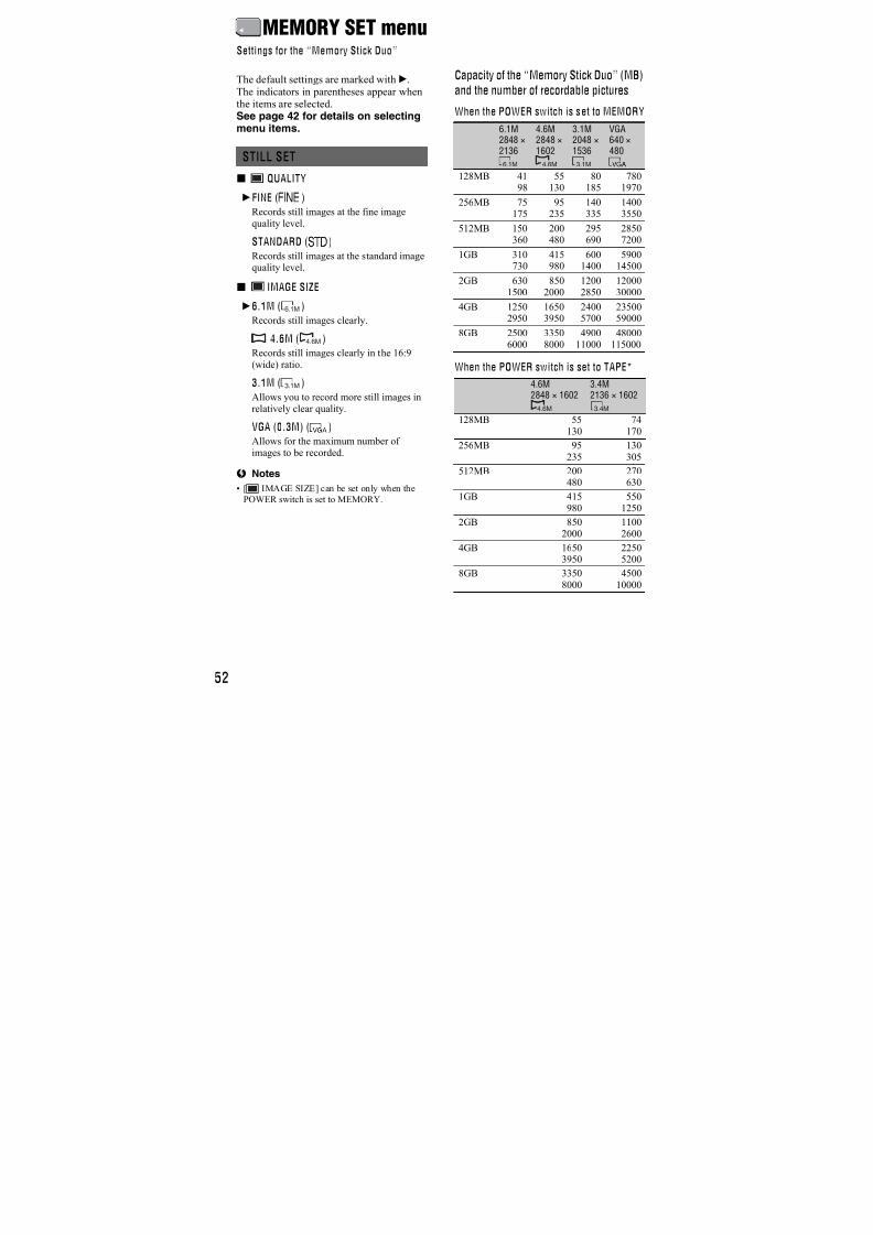
7/18/2019 SONY+HVR-HD1000 SERVICE MANUAL
http://slidepdf.com/reader/full/sonyhvr-hd1000-service-manual 333/42536
Searching for the starting point
END SEARCH will not work once youeject the cassette after you have recorded onthe tape.Make sure that the POWER switch is set toTAPE.
Touch t .
The last scene of the most recentrecording is played back for about 5seconds, and the camcorder enters the
standby mode at the point where the lastrecording has finished.
b Notes
• END SEARCH will not work correctly whenthere is a blank section between recorded
sections on the tape.
z Tips
• You can also select [END SEARCH] from themenu. When the POWER switch is set to
PLAY/EDIT. select the [END SEARCH] short-
cut in Personal Menu (p. 42).
You can view about 2 seconds of the scenerecorded just before you stopped the tape.Make sure that the POWER switch is set toTAPE.
Touch t .
The last 2 seconds (approx.) of the mostrecently recorded scene are played back.Then, your camcorder is set to standby.
Searching for the last scene ofthe most recent recording (ENDSEARCH)
END SEARCH
EXECUTING
CANCEL
0:00:00160min
Touch here to cancel the operation.
Reviewing the most recentlyrecorded scenes (Rec review)
0:00:00STBY60min
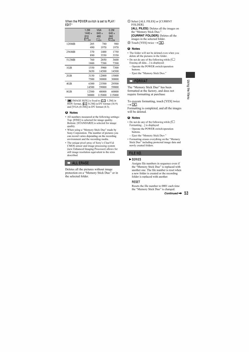
7/18/2019 SONY+HVR-HD1000 SERVICE MANUAL
http://slidepdf.com/reader/full/sonyhvr-hd1000-service-manual 334/42537
R e c o r d i n g / P l a y b a c k
Playing the picture on a TV
Connection methods and image qualitydiffer depending on what type of TV isconnected and connectors used.Use the supplied AC Adaptor as the power
source (p. 21).Refer also to the instruction manualssupplied with the device to be connected.
b Notes
• Make all menu settings on your camcorder
before connecting. The TV may not recognize
the video signal properly if the [VCR HDV/DV]
or [i.LINK CONV] setting is changed after the
TV and your camcorder were connected with an
i.LINK cable.
• Pictures recorded in the DV format are played
back as SD (standard definition) imagesregardless of the connection.
• When recording, set [X.V.COLOR] to [ON] to play back on an x.v.Color-compliant TV (p. 51).
Some settings may need to be adjusted on the
TV when playing back.
Jacks on your camcorder
Open the jack cover in the direction of the
arrow and connect the cable.
Lift up the bottom of the jack cover, thenrotate in the direction of the arrow.
Continued,
7/18/2019 SONY+HVR-HD1000 SERVICE MANUAL
http://slidepdf.com/reader/full/sonyhvr-hd1000-service-manual 335/42538
Connecting to a high definition TV
: Signal flow, ( ): Reference pages
Type Camcorder Cable TV Menu Setting
(STANDARD SET) [VCR HDV/DV]t [AUTO] (59)[COMPONENT]t [1080i/576i] (62)
• An A/V connecting cable is also needed to output audio signals. Connect the white and red plugs of the A/
V connecting cable to the audio input jack of your TV.
B CA
HDMI i.LINKCOMPONENT IN
AUDIO
(for HDV1080i)
HD (high definition) image quality
• An HDV formatted picture is played back as it is
(HD image quality).
• A DV formatted picture is played back as it is (SD image quality).
A Component video cable(optional)
A/V connecting cable(supplied)
(Green) Y
(Blue) PB /CB(Red) PR /CR
(White)
(Red)
(Yellow)
Playing the picture on a TV (Continued)
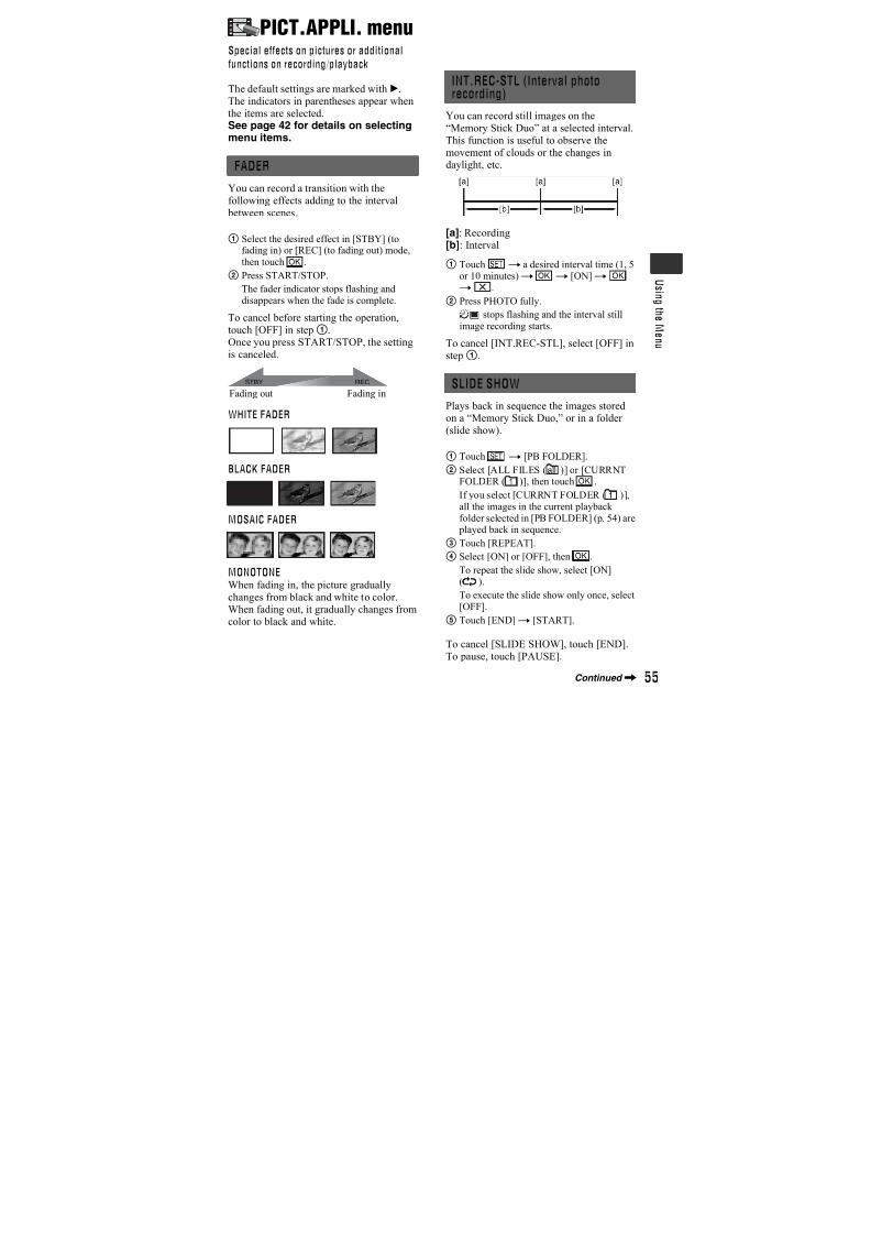
7/18/2019 SONY+HVR-HD1000 SERVICE MANUAL
http://slidepdf.com/reader/full/sonyhvr-hd1000-service-manual 336/42539
R e c o r d i n g / P l a y b a c k
(STANDARD SET)[VCR HDV/DV]t [AUTO] (59)
• Use an HDMI cable with the HDMI logo (on the front cover).
• Pictures in the DV format are not output from the HDMI OUT jack, if copyright protection signals are
recorded in the pictures.
• DV format pictures input to the camcorder via i.LINK cable (p. 71) cannot be output.
• Your TVs may not function correctly (e.g., no sound or image). Do not connect the HDMI OUT jack ofyour camcorder and HDMI OUT jack of an external device with the HDMI cable. This may cause a
malfunction.
(STANDARD SET)[VCR HDV/DV]t [AUTO] (59)[DOWN CONVERT]t [i.LINK CONV]t [OFF] (62)
• Your TV needs to have an i.LINK jack compatible with HDV1080i specification. For details,confirm the specifications of your TV.
• If your TV is not compatible with HDV1080i specification, connect your camcorder and TV with theoptional component video cable and supplied A/V connecting cable as illustrated in .
• The TV needs to be set so that it recognizes that the camcorder is connected. See the instruction manualssupplied with your TV.
Connecting to a 16:9 (wide) or 4:3 TV
: Signal flow, ( ): Reference pages
Type Camcorder Cable TV Menu Setting
HDMIINB HDMI cable (optional)
Ci.LINK cable (optional)
E F G
S VIDEO VIDEO/AUDIO
VIDEO/AUDIO
i.LINK
D
COMPONENT IN
AUDIO
SD (standard definition) image quality• An HDV formatted picture is down converted to DV format
(SD image quality) and played back.
• A DV formatted picture is played back as it is (SD image quality).
Continued,
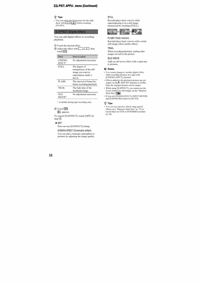
7/18/2019 SONY+HVR-HD1000 SERVICE MANUAL
http://slidepdf.com/reader/full/sonyhvr-hd1000-service-manual 337/42540
To set the aspect ratio according to the connected TV (16:9/4:3)
Change the [VIDEO OUT] setting to match your TV.
b Notes
• When you play back a tape recorded in the DV format on a 4:3 TV not compatible with the 16:9 signal, set
[ WIDE SELECT] to [4:3] on your camcorder when recording a picture (p. 60).
: Signal flow, ( ): Reference pages
Type Camcorder Cable TV Menu Setting
(STANDARD SET)[VCR HDV/DV]t [AUTO] (59)[COMPONENT]t
[576i] (62)[DOWN CONVERT]t [VIDEO OUT]t [SQUEEZE]/[LETTERBOX]/[EDGE CROP](62)
• A/V connecting cable is also needed to output audio signals. Connect the white and red plugs of the A/V
connecting cable to the audio input jack of your TV.
(STANDARD SET)[VCR HDV/DV]t [AUTO] (59)[DOWN CONVERT]t [i.LINK CONV]t [ON:SQUEEZE]/
[ON:EDGE CROP] (62)
• The TV needs to be set so that it recognizes that the camcorder is connected. See the instruction manuals
supplied with your TV.
D Component video cable(optional)
A/V connecting cable(supplied)
(Green) Y
(Blue) PB /CB
(Red) PR /CR
(White)
(Red)
(Yellow)
Ei.LINK cable (optional)
Playing the picture on a TV (Continued)
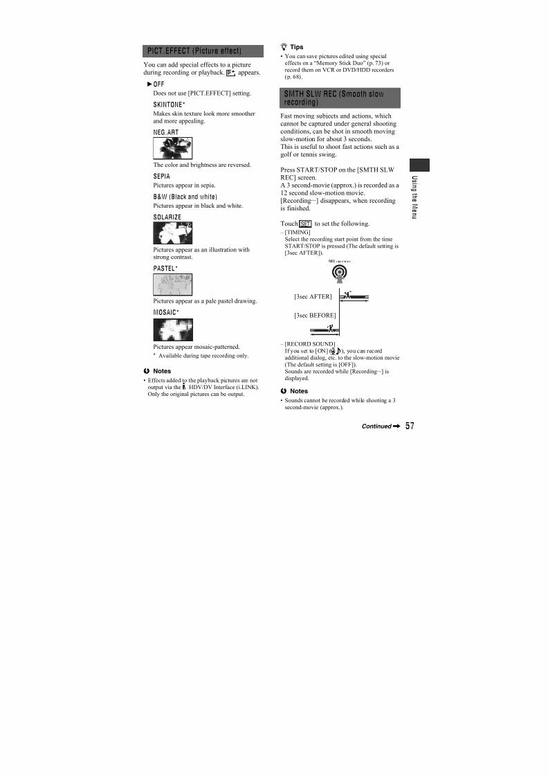
7/18/2019 SONY+HVR-HD1000 SERVICE MANUAL
http://slidepdf.com/reader/full/sonyhvr-hd1000-service-manual 338/42541
R e c o r d i n g / P l a y b a c k
When connecting to your TV via a VCR
Select one of the connecting methods on page 68, according to the input jack of theVCR. Connect your camcorder to the LINEIN input on the VCR using the A/Vconnecting cable. Set the input selector on
the VCR to LINE (VIDEO 1, VIDEO 2,etc.).
When your TV is monaural (When yourTV has only one audio input jack)
Connect the yellow plug of the A/Vconnecting cable to the video input jack andconnect the white (left channel) or the red(right channel) plug to the audio input jackof your TV or VCR.
If your TV/VCR has a 21-pin adaptor(EUROCONNECTOR)
Use a 21-pin adaptor (optional) to view playback pictures.
z Tips
• The HDMI (High Definition MultimediaInterface) is an interface to send both video/
audio signals. Connecting HDMI OUT jack andexternal device with a cable supplies high
quality images and digital audio.
• If you connect your camcorder to your TV using
more than one type of cable to output images
from a jack other than the i.LINK jack, the orderof priority of the output signals is as follows:
HDMIt component videot S VIDEOt
audio/video.
• See page 99 for the details of i.LINK.
(STANDARD SET)[VCR HDV/DV]t[AUTO] (59)[DOWN CONVERT]t [VIDEO OUT]t [SQUEEZE]/[LETTERBOX]/[EDGE CROP](62)
• When connecting only an S VIDEO plug (S VIDEO channel), audio signals are not output. To output
audio signals, connect the white and red plugs of the A/V connecting cable with an S VIDEO cable to the
audio input jack of your TV.
• This connection produces higher resolution pictures compared with the A/V connecting cable (Type ).
(STANDARD SET)[VCR HDV/DV]t [AUTO] (59)[DOWN CONVERT]t
[VIDEO OUT]t [SQUEEZE]/[LETTER
BOX]/[EDGE CROP](62)
: Signal flow, ( ): Reference pages
Type Camcorder Cable TV Menu Setting
A/V connecting cable withS VIDEO (optional)
(Yellow)
(White)
(Red)
A/V connecting cable(supplied) (Yellow)
(White)
(Red)
7/18/2019 SONY+HVR-HD1000 SERVICE MANUAL
http://slidepdf.com/reader/full/sonyhvr-hd1000-service-manual 339/42542
Using the Menu
Using the menu items
1 Slide the POWER switch to the desired position while
pressing the green button.
TAPE: settings on a tapeMEMORY: settings on a “Memory Stick Duo”
PLAY/EDIT: settings for viewing/editing
2 Touch the LCD screen to select the menu item.
Unavailable items will be grayed out.
x To use the short-cuts ofPersonal Menu
On Personal Menu, short-cuts forfrequently used menu items are added.
z Tips
• You can customize Personal Menu as you
like (p. 66).
1 Touch .
2 Touch the desired item.
If the desired item is not displayed onthe screen, touch / until the itemis displayed.
3 Select the desired setting, then touch
.
x To use menu itemsYou can customize menu items that are
not added to Personal Menu.
1 Touch t [MENU].
2 Select the desired menu.
Touch / to select the item, thentouch (The process in step3 isthe same as that in step2).
3 Select the desired item.
4 Customize the item.
After finishing the settings, toucht
(close) to hide the menuscreen.
If you decide not to change the setting,touch to return to the previousscreen.
MENU
1/3
0:00:0060min STBY
STATUS
CHECK
RING
SETL
WHITE
BAL.ZEBRA
MIC
LEVEL
7/18/2019 SONY+HVR-HD1000 SERVICE MANUAL
http://slidepdf.com/reader/full/sonyhvr-hd1000-service-manual 340/42543
U s i n g t h e M e n u
Menu items Available menu items (z) vary depending on the position of theswitch.
Position TAPE MEMORY PLAY/EDIT
CAMERA SET menu (p. 45)
SCENE SELECT z z –
SPOT METER z z –
EXPOSURE z z –
WHITE BAL. z z –
SHARPNESS z z –
SHUTTR SPEED z z –
AUTOSLW SHTR z – –
AE SHIFT z z –
CAMERA COLOR z z –
WB SHIFT z z –
SPOT FOCUS z z –
FOCUS z z –TELE MACRO z z –
SUPER NS z – –
NS LIGHT z z –
COLOR SLOW S z z –
ZEBRA z z –
HISTOGRAM z z –
SELF-TIMER z z –
DIGITAL ZOOM z – –
STEADYSHOT z z –
CONV.LENS z z –
RING SETTING z z –
X.V.COLOR z – –
MEMORY SET menu (p. 52)
STILL SET – z z
ALL ERASE – – z
FORMAT – z z
FILE NO. – z zNEW FOLDER – z z
REC FOLDER – z z
PB FOLDER – – z
PICT.APPLI. menu (p. 55)
FADER z – –
INT.REC-STL – z –
SLIDE SHOW – – z
D.EFFECT z – z
PICT.EFFECT z – z
SMTH SLW REC z – –
PictBridge PRINT – – z
Continued,
7/18/2019 SONY+HVR-HD1000 SERVICE MANUAL
http://slidepdf.com/reader/full/sonyhvr-hd1000-service-manual 341/42544
USB SELECT – – z
EDIT/PLAY menu (p. 58)
VAR.SPD PB – – z
REC CTRL – – z
END SEARCH z – z
STANDARD SET menu (p. 59)
VCR HDV/DV – – z
REC FORMAT z – –
DV SET z – z
VOLUME z z z
MIC LEVEL z – –
AU.LVL DISP z – –
LCD/VF SET z z z
COMPONENT z z z
DOWN CONVERT z z z
STATUS CHECK z – z
GUIDEFRAME z z –
COLOR BAR z – –
DATA CODE – – z
REMAINING z – z
REC LAMP z z –
BEEP z z zDISP OUTPUT z z z
MENU ROTATE z z z
CALIBRATION – – z
QUICK REC z – –
TIME/LANGU. menu (p. 65)
CLOCK SET z z z
WORLD TIME z z z
LANGUAGE z z z
Position TAPE MEMORY PLAY/EDIT
Menu items (Continued)
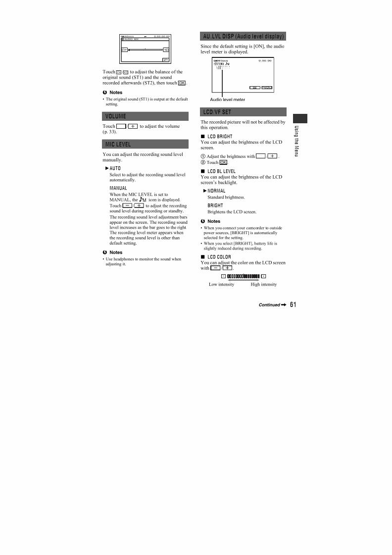
7/18/2019 SONY+HVR-HD1000 SERVICE MANUAL
http://slidepdf.com/reader/full/sonyhvr-hd1000-service-manual 342/42545
U s i n g t h e M e n u
CAMERA SET menuSettings to adjust your camcorder to the
recording conditions
The default settings are marked with B.The indicators in parentheses appear when
the items are selected.See page 42 for details on selectingmenu items.
You can record pictures effectively invarious situations with the [SCENESELECT] function.
B AUTO
Select to automatically record pictureseffectively without the [SCENE SELECT]function.
TWILIGHT* ( )
Select to maintain the darkeningatmosphere of the distant surroundings intwilight scenes.
CANDLE ( )
Select to maintain the dim atmosphere of acandlelit scene.
SUNRSE SUNSET (Sunrise and sunset)*
( )Select to maintain the atmosphere ofsituations such as sunsets and sunrises.
FIREWORKS* ( )
Select to record all the splendor offireworks.
SCENE SELECT
LANDSCAPE* ( )
Select to shoot distant subjects clearly.This setting also prevents your camcorderfrom focusing on glass or metal mesh in
windows between the camcorder and thesubject.
PORTRAIT (Soft portrait) ( )
Select to bring out the subject such as people or flowers while creating a soft background.
SPOTLIGHT** ( )
Select to prevent people’s faces fromappearing excessively white when subjectsare lit by strong light.
BEACH** ( )
Select to prevent people’s faces fromappearing dark in strong light or reflectedlight, such as at a beach in midsummer.
SNOW** ( )Select this when shooting in very bright,white conditions, such as on a ski slope;otherwise picture may appear too dark.
* Adjusted to focus on subjects farther away
only.
** Adjusted not to focus on subjects a shortdistance away.
Continued,
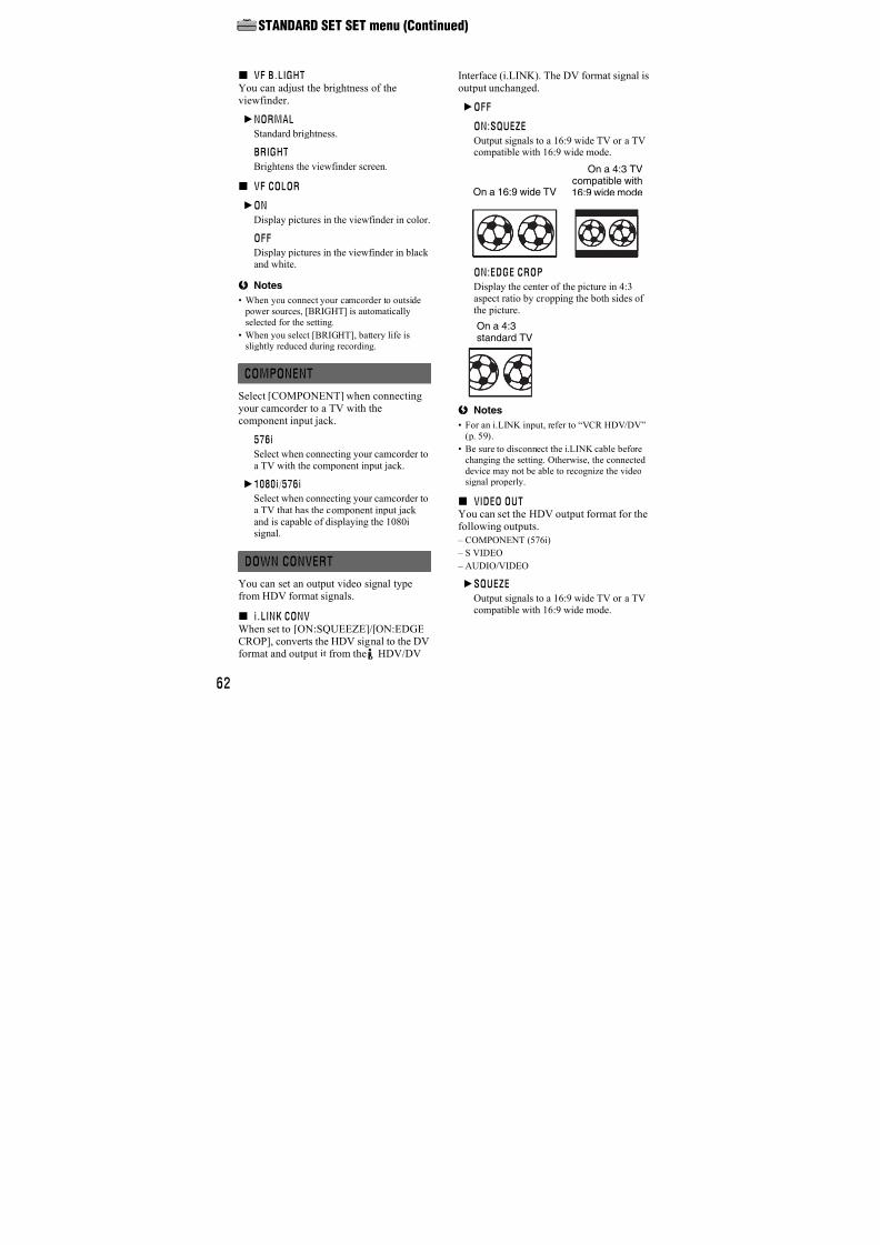
7/18/2019 SONY+HVR-HD1000 SERVICE MANUAL
http://slidepdf.com/reader/full/sonyhvr-hd1000-service-manual 343/42546
b Notes
• If you set [SCENE SELECT], the settings of[SHUTTR SPEED] and [WHITE BAL.] are
canceled.
You can adjust and fix the exposure to thesubject, so that it is recorded in suitable
brightness even when there is strongcontrast between the subject and the
background, such as subjects in thespotlight on stage.
1 Touch the point where you want to fix andadjust the exposure on the screen.
appears.
2 Touch [END].
To return the setting to automatic exposure,touch [AUTO]t [END].
b Notes
• If you set [SPOT METER], [EXPOSURE] is
automatically set to [MANUAL].
You can fix the brightness of a picturemanually. Adjust the brightness when thesubject is much brighter or darker than the
background.
1 Touch [MANUAL].
appears.
2 Adjust the exposure by touching /.
3 Touch .
To return the setting to automatic exposure,touch [AUTO]t .
z Tips
• You can also adjust the setting manually using
the RING (p. 31).
You can adjust the color balance to the brightness of the recording environment.
B AUTO
The white balance is adjustedautomatically.
OUTDOOR ( )
The white balance is appropriatelyadjusted for the following recording
conditions: – Outdoors
– Night views, neon signs and fireworks
– Sunrise or sunset
– Under daylight fluorescent lamps
INDOOR (n)
The white balance is appropriatelyadjusted for the following recordingconditions:
– Indoors
– At party scenes or studios where the lighting
conditions change quickly
– Under video lamps in a studio, or under
sodium lamps or incandescent-like color
lamps
ONE PUSH ( )
The white balance will be adjustedaccording to the ambient light.
1 Touch [ONE PUSH].
2 Frame a white object such as a piece of paper, to fill the screen under the samelighting conditions as you will shootthe subject.
SPOT METER (Flexible spotmeter)
EXPOSURE
1
2
2
1 3
WHITE BAL. (White balance)
CAMERA SET menu (Continued)
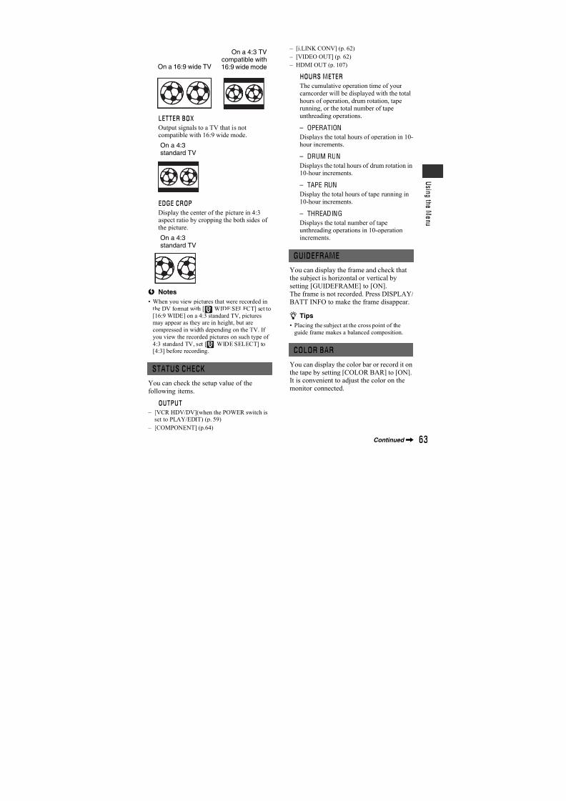
7/18/2019 SONY+HVR-HD1000 SERVICE MANUAL
http://slidepdf.com/reader/full/sonyhvr-hd1000-service-manual 344/42547
U s i n g t h e M e n u
3 Touch [ ].
flashes quickly. When the white balance has been adjusted and stored inthe memory, the indicator stops
flashing.
b Notes
• Set [WHITE BAL.] to [AUTO] or adjust the
color in [ONE PUSH] under white or cool white
fluorescent lamps.
• When you select [ONE PUSH], keep framing
white objects while is flashing quickly.
• flashes slowly if [ONE PUSH] could not
be set.
• When [ONE PUSH] was selected, if keeps
flashing after touching , set [WHITE
BAL.] to [AUTO].
• If you set [WHITE BAL.], [SCENE SELECT]returns to [AUTO].
z Tips
• If you have changed the battery pack while
[AUTO] was selected, or taken your camcorder
outdoors after inside use (or vice versa), select[AUTO] and aim your camcorder at a nearby
white object for about 10 seconds for better
color balance adjustment.
• When the white balance has been set with [ONE
PUSH], if you change the [SCENE SELECT]
settings, or bring your camcorder outdoors from
inside the house, or vice versa, you need to redo
the [ONE PUSH] procedure to readjust the
white balance.
You can adjust the sharpness of the imageoutline with / . appears whenthe sharpness is anything other than thedefault setting.
You can manually adjust and fix the shutterspeed for your convenience. Depending onthe shutter speed, you can make the subjectlook still, or emphasize movement of thesubject.
B AUTO
Select to adjust the shutter speedautomatically.
MANUAL( )Adjust the shutter speed using /
.
You can select a shutter speed between 1/3and 1/10000 second when the POWERswitch is set to TAPE, and between 1/3 and1/425 second when the POWER switch isset to MEMORY.
b Notes
• When the shutter speed is set between 1/600 to
1/10000 second, still images cannot be recorded.
• For example, if you select 1/100 second, [100]
appears on the screen.
• At a slow shutter speed, automatic focus may be
lost. Adjust the focus manually, using a tripod,etc.
• When recording under a discharge tube such asa fluorescent lamp, sodium lamp or mercury
lamp, horizontal bands may appear in the screen
depending on the shutter speed.
z Tips
• You can also adjust the setting manually usingthe RING (p. 31).
When you set [AUTOSLW SHTR] to[ON], the shutter speed is slowed downautomatically to 1/25 second in dark places.
You can adjust the exposure using(dark)/ (bright). and the settingvalue appear when [AE SHIFT] is anythingother than the default setting.
SHARPNESS
SHUTTR SPEED
Soften Sharpen
AUTOSLW SHTR (Auto slowshutter)
AE SHIFT
120, 150, 215Slower Faster
Continued,
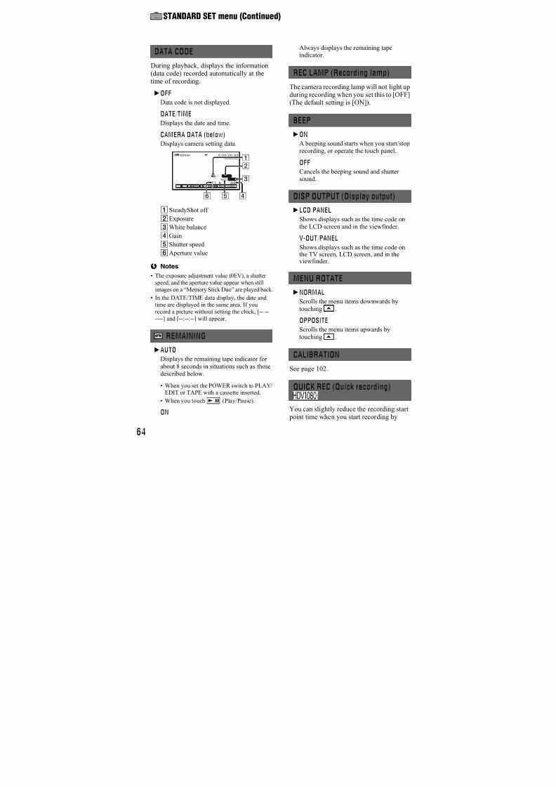
7/18/2019 SONY+HVR-HD1000 SERVICE MANUAL
http://slidepdf.com/reader/full/sonyhvr-hd1000-service-manual 345/42548
z Tips
• Touch if the subject is white or the backlight is bright, or touch if the subject
is black or the light is dim.
• You can adjust the automatic exposure level to brighter or darker when [EXPOSURE] is set to
[AUTO].
• You can also adjust the setting manually using
the RING (p. 31).
You can adjust the color intensity with/ . appears when [CAMERA
COLOR] is anything other than the defaultsetting.
You can adjust the white balance to thedesired setting using / .
and the setting value appear when [WBSHIFT] is anything other than the defaultsetting.
z Tips
• When the white balance is set to a lower value,
pictures appear bluish, and when set to a higher
value, pictures appear reddish.
• You can also adjust the setting manually using
the RING (p. 31).
You can select and adjust the focal point toa subject not located in the center of thescreen.
1 Touch the subject on the screen.
9 appears.
2 Touch [END].
To adjust the focus automatically, touch[AUTO] t [END] in step1.
b Notes
• If you set [SPOT FOCUS], [FOCUS] is
automatically set to [MANUAL].
You can adjust the focus manually. You canselect this function also when you want tofocus on a certain subject intentionally.
1 Touch [MANUAL].
9 appears.
2 Touch (focusing on close subjects)/ (focusing on distant subjects) to
sharpen the focus. appears when the
focus cannot be adjusted any closer, andappears when the focus cannot be adjustedfarther away.
3 Touch .
To adjust the focus automatically, touch[AUTO] t in step1.
b Notes
• The minimum possible distance betweencamcorder and subject while maintaining sharp
focus is about 1 cm (about 13/32 in.) for wideangle and about 80 cm (about 2 5/8 feet) for
telephoto.
z Tips
• It is easier to focus on the subject by moving the
power zoom lever towards T (telephoto) toadjust the focus, then towards W (wide angle) to
adjust the zoom for recording. When you want
to record a subject at close range, move the power zoom lever to W (wide angle), then
adjust the focus.
• You can also adjust the focus manually using
the RING (p. 31).
CAMERA COLOR
WB SHIFT (White Balance Shift)
SPOT FOCUS
Decreases colorintensity
Increases colorintensity
1
2
FOCUS
CAMERA SET menu (Continued)
7/18/2019 SONY+HVR-HD1000 SERVICE MANUAL
http://slidepdf.com/reader/full/sonyhvr-hd1000-service-manual 346/42549
U s i n g t h e M e n u
This is useful to shoot small subjects, suchas flowers or insects. You can blur out
backgrounds and the subject stands outclearer.When you set [TELE MACRO] to [ON]( ), the zoom (p. 30) moves to the top ofthe T (Telephoto) side automatically andallows for recording subjects at a closedistance as down to about 45 cm(17 3/4 in.).
To cancel, touch [OFF], or zoom to wide-angle (W side).
b Notes
• When recording a distant subject, focusing may
be difficult and can take some time.
• Adjust the focus manually ([FOCUS], p. 48)
when it is hard to focus automatically.
The picture will be recorded at a maximumof 16 times the sensitivity of NightShotrecording if you set [SUPER NS] to [ON]while the NIGHTSHOT switch (p. 31) isalso set to ON.
and [“SUPER NIGHTSHOT”] appear
on the screen.To return to the normal setting, set [SUPER
NS] to [OFF], or set the NIGHTSHOTswitch to OFF.
b Notes
• Do not use NightShot/[SUPER NS] in bright
places. This may cause a malfunction.
• Do not cover the infrared port with your fingers
or other objects.
• Remove the conversion lens (optional).• Adjust the focus manually ([FOCUS], p. 48)
when it is hard to focus automatically.
• The shutter speed of your camcorder changes
depending on the brightness. The motion of the
picture may slow down in this case.
When using either the NightShot (p. 31) or[SUPER NS] (p. 49) function to record, youcan record clearer pictures by setting [NSLIGHT], which emits infrared light(invisible), to [ON] (the default setting).
b Notes
• Do not cover the infrared port with your fingers
or other objects.• Remove the conversion lens (optional).
• The maximum shooting distance using [NSLIGHT] is about 3 m (10 feet).
When you set [COLOR SLOW S] to [ON],you can record an image brighter in color
even in dark places. and [COLOR SLOW SHUTTER]appear on the screen.
To cancel [COLOR SLOW S], touch[OFF].
b Notes
• Adjust the focus manually ([FOCUS], p. 48)
when it is hard to focus automatically.
• The shutter speed of your camcorder changes
depending on the brightness. The motion of the picture may slow down at this time.
TELE MACRO
SUPER NS (Super NightShot)
NS LIGHT (NightShot Light)
COLOR SLOW S (Color SlowShutter)
Continued,
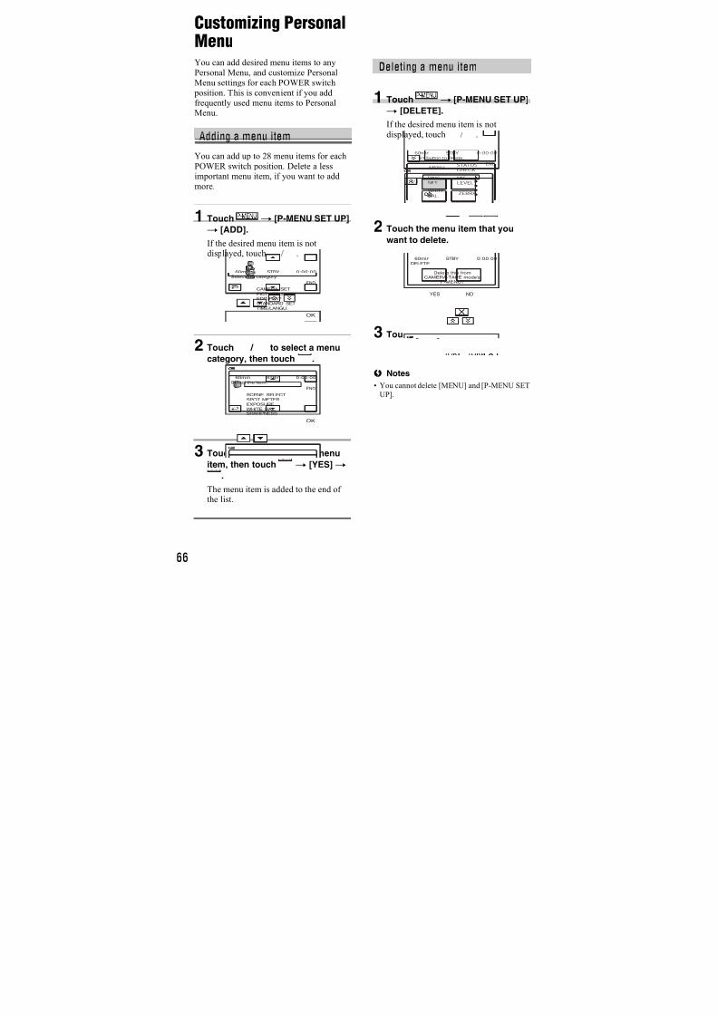
7/18/2019 SONY+HVR-HD1000 SERVICE MANUAL
http://slidepdf.com/reader/full/sonyhvr-hd1000-service-manual 347/42550
Diagonal stripes appear in portions of thescreen where brightness is at a preset level.This is useful as a guide when adjusting the
brightness. When you change the defaultsetting, is displayed. The zebra patternis not recorded.
B OFF
The zebra pattern is not displayed.
70
The zebra pattern appears at a screen
brightness level of about 70 IRE.100
The zebra pattern appears at a screen brightness level of about 100 IRE orhigher.
b Notes
• Portions of the screen where brightness is about100 IRE or higher may appear overexposed.
z Tips
• IRE represents the screen brightness.
When you set [HISTOGRAM] to [ON], the[HISTOGRAM] (a graph to display adistribution of tones in your picture)window appears on the screen.This item is useful when you adjust
exposure. You can adjust the [EXPOSURE]or [AE SHIFT] checking the[HISTOGRAM] window. The[HISTOGRAM] will not be recorded on atape or “Memory Stick Duo.”
z Tips
• The left area on the graph shows the darkerareas of the picture while the right area shows
the brighter areas.
A still image is recorded after about 10seconds.
Press PHOTO when [SELF-TIMER] is setto [ON] and appears.
To cancel the count down, touch [RESET].
To cancel the self-timer, select [OFF].
You can select the maximum zoom level incase you want to zoom to a level greaterthan 10 × (the default setting) whilerecording on a tape. Note that the imagequality decreases when you are using thedigital zoom.
B OFFUp to 10 × zoom is performed optically.
20 ×
Up to 10 × zoom is performed optically,and after that, up to 20 × zoom is performed digitally.
You can compensate for camera shake (Thedefault setting is [ON]). Set[STEADYSHOT] to [OFF] ( ) whenusing a tripod (optional), then the image
becomes natural.
ZEBRA
HISTOGRAM
80
Brighter Darker
Brightness
P i x e l s
SELF-TIMER
DIGITAL ZOOM
STEADYSHOT
The right side of the bar shows the digitalzooming factor. The zooming zoneappears when you select the zoominglevel.
CAMERA SET menu (Continued)
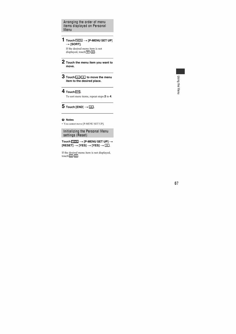
7/18/2019 SONY+HVR-HD1000 SERVICE MANUAL
http://slidepdf.com/reader/full/sonyhvr-hd1000-service-manual 348/42551
U s i n g t h e M e n u
When using an optional conversion lens,use this function to record using theoptimum compensation for camera shakefor each lens.
B OFF
Select this when the conversion lens(optional) is not used.
WIDE CONV. ( )
Select this to use the wide conversion lens(optional).
TELE CONV. ( )Select this to use the tele conversion lens(optional).
You can select a menu items to assign to theRING. For details, see page 31.
When recording, set to [ON] to capturewider range of colors.Various colors such as the brilliant color offlowers and turquoise blue of the sea can bemore faithfully reproduced.
b Notes
• Set [X.V.COLOR] to [ON] only when the
recorded content will be played back on an
x.v.Color-compliant TV. Otherwise, set to[OFF] (the default setting).
• If the movie recorded with this function [ON] is played back on a non-x.v.Color-compliant TV,
the color may not be reproduced correctly.
• [X.V.COLOR] cannot be set to [ON] when:
– Recording in DV format
– A movie is being recorded.
CONV.LENS
RING SETTING
X.V.COLOR
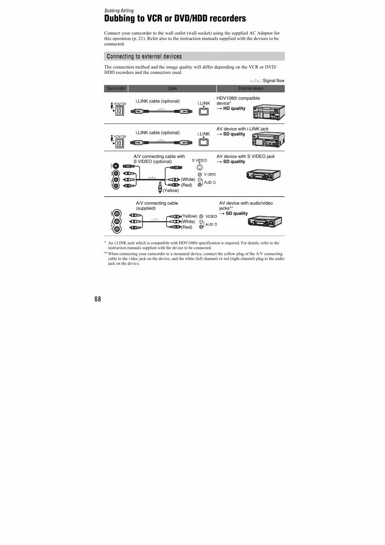
7/18/2019 SONY+HVR-HD1000 SERVICE MANUAL
http://slidepdf.com/reader/full/sonyhvr-hd1000-service-manual 349/42552
MEMORY SET menuSettings for the “Memory Stick Duo”
The default settings are marked with B.The indicators in parentheses appear whenthe items are selected.See page 42 for details on selectingmenu items.
x QUALITY
B FINE ( )
Records still images at the fine imagequality level.
STANDARD ( )Records still images at the standard imagequality level.
x IMAGE SIZE
B 6.1M ( )
Records still images clearly.
4.6M ( )
Records still images clearly in the 16:9
(wide) ratio.3.1M ( )
Allows you to record more still images inrelatively clear quality.
VGA (0.3M) ( )
Allows for the maximum number ofimages to be recorded.
b Notes
• [ IMAGE SIZE] can be set only when thePOWER switch is set to MEMORY.
STILL SET
6.1M
4.6M
3.1M
Capacity of the “Memory Stick Duo” (MB)
and the number of recordable pictures
When the POWER switch is set to MEMORY
When the POWER switch is set to TAPE*
6.1M2848 ×2136
4.6M2848 ×1602
3.1M2048 ×1536
VGA640 ×480
128MB 4198
55130
80185
7801970
256MB 75175
95235
140335
14003550
512MB 150360
200480
295690
28507200
1GB 310730
415980
6001400
590014500
2GB 6301500
8502000
12002850
1200030000
4GB 12502950
16503950
24005700
2350059000
8GB 25006000
33508000
490011000
48000115000
4.6M2848 × 1602
3.4M2136 × 1602
128MB 55130
74170
256MB 95235
130305
512MB 200480
270630
1GB 415980
5501250
2GB 8502000
11002600
4GB 16503950
22505200
8GB 33508000
450010000
6.1M 4.6M 3.1M
4.6M 3.4M
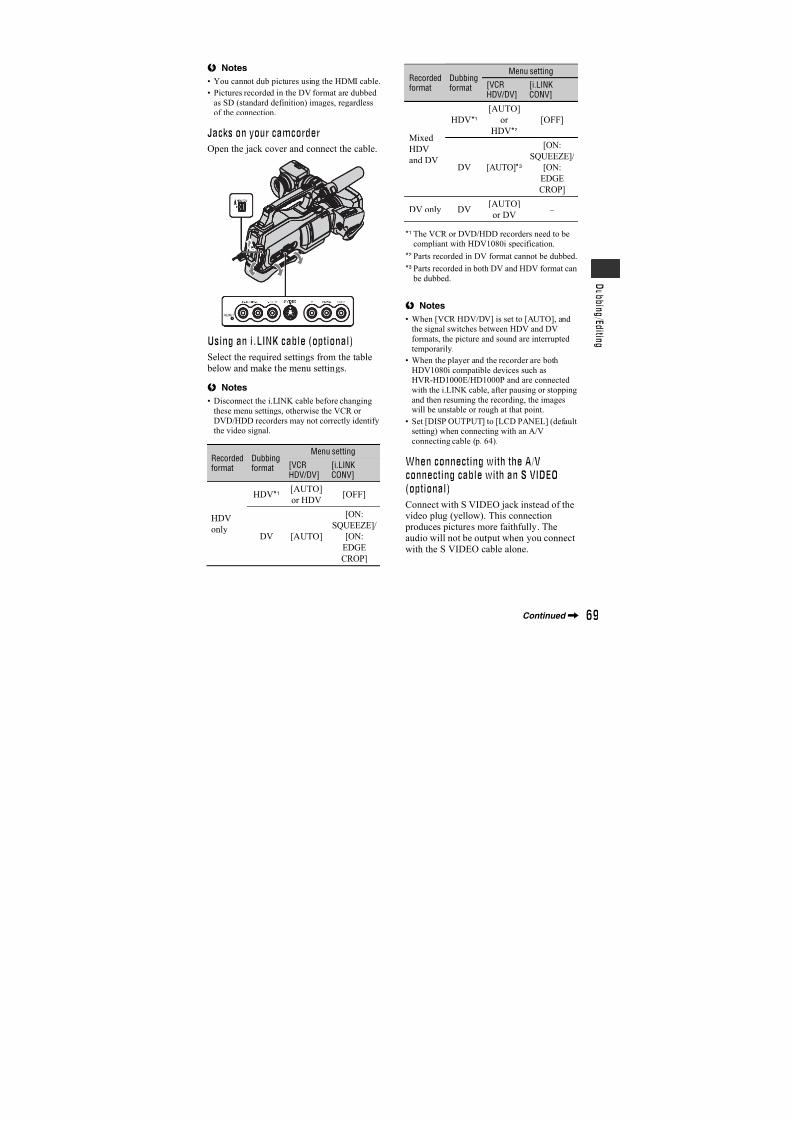
7/18/2019 SONY+HVR-HD1000 SERVICE MANUAL
http://slidepdf.com/reader/full/sonyhvr-hd1000-service-manual 350/42553
U s i n g t h e M e n u
When the POWER switch is set to PLAY/ EDIT*
* [ IMAGE SIZE] is fixed to [ 1.2M] in
HDV format, [ 0.2M] in DV format (16:9)and [VGA (0.3M)] in DV format (4:3).
b Notes
• All numbers measured at the following settings:
Top: [FINE] is selected for image quality.Bottom: [STANDARD] is selected for image
quality.
• When using a “Memory Stick Duo” made by
Sony Corporation. The number of pictures you
can record varies depending on the recording
environment and the recording media.
• The unique pixel array of Sony’s ClearVid
CMOS sensor and image processing system
(new Enhanced Imaging Processor) allows for
still image resolution equivalent to the sizes
described.
Deletes all the pictures without image protection on a “Memory Stick Duo” or in
the selected folder.
1 Select [ALL FILES] or [CURRNTFOLDER].
[ALL FILES]: Deletes all the images onthe “Memory Stick Duo.”
[CURRNT FOLDER]: Deletes all theimages in the selected folder.
2 Touch [YES] twicet .
b Notes
• The folder will not be deleted even when youdelete all the pictures in the folder.
• Do not do any of the following while [
Erasing all data…] is displayed:
– Operate the POWER switch/operation
buttons. – Eject the “Memory Stick Duo.”
The “Memory Stick Duo” has beenformatted at the factory, and does notrequire formatting at purchase.
To execute formatting, touch [YES] twice
t .Formatting is completed, and all the imageswill be deleted.
b Notes
• Do not do any of the following while [
Formatting…] is displayed:
– Operate the POWER switch/operation
buttons.
– Eject the “Memory Stick Duo.”
• Formatting erases everything on the “Memory
Stick Duo” including protected image data and
newly created folders.
B SERIES
Assigns file numbers in sequence even ifthe “Memory Stick Duo” is replaced withanother one. The file number is reset whena new folder is created or the recording
folder is replaced with another.
RESET
Resets the file number to 0001 each timethe “Memory Stick Duo” is changed.
1.2M1440 ×810
VGA640 ×480
0.2M640 ×360
128MB 205
490
780
1970
980
1970
256MB 370
890
1400
3550
1750
3550
512MB 760
1800
2850
7200
3600
7200
1GB 1550
3650
5900
14500
7300
14500
2GB 3150
7500
12000
30000
15000
30000
4GB 6300
14500
23500
59000
29500
59000
8GB 12500
30000
48000
115000
60000
115000
ALL ERASE
1.2M
FORMAT
FILE NO.
Continued,
7/18/2019 SONY+HVR-HD1000 SERVICE MANUAL
http://slidepdf.com/reader/full/sonyhvr-hd1000-service-manual 351/42554
You can create a new folder (102MSDCFto 999MSDCF) on a “Memory Stick Duo.”When 9,999 images are stored in the currentfolder, a new folder is automatically createdfor storing subsequent images.
Touch [YES]t .
b Notes
• You cannot delete the created folders using yourcamcorder. You will have to format the
“Memory Stick Duo” (p. 53), or delete them
using your computer.• The number of recordable pictures on a
“Memory Stick Duo” may decrease as the
number of folders increases.
Select the folder to be used for recordingwith / , then touch .
b Notes
• As the default setting, pictures are saved in the
101MSDCF folder.
• Once you record a picture in a folder, the samefolder will be set as the default folder for
playback.
Select the playback folder with / ,then touch .
NEW FOLDER
REC FOLDER (Recording folder)
PB FOLDER (Playback folder)
MEMORY SET menu (Continued)
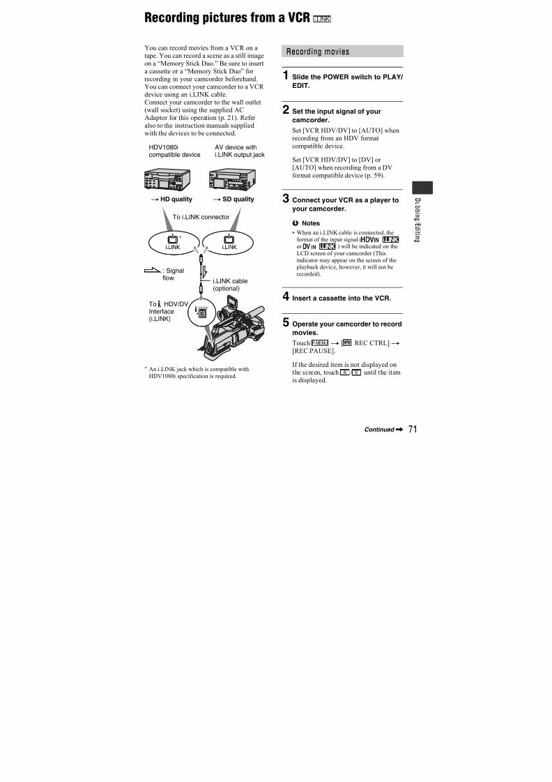
7/18/2019 SONY+HVR-HD1000 SERVICE MANUAL
http://slidepdf.com/reader/full/sonyhvr-hd1000-service-manual 352/42555
U s i n g t h e M e n u
PICT.APPLI. menuSpecial effects on pictures or additional
functions on recording/playback
The default settings are marked with B.The indicators in parentheses appear whenthe items are selected.
See page 42 for details on selectingmenu items.
You can record a transition with thefollowing effects adding to the interval
between scenes.
1 Select the desired effect in [STBY] (tofading in) or [REC] (to fading out) mode,then touch .
2 Press START/STOP.
The fader indicator stops flashing anddisappears when the fade is complete.
To cancel before starting the operation,touch [OFF] in step1.Once you press START/STOP, the settingis canceled.
WHITE FADER
BLACK FADER
MOSAIC FADER
MONOTONEWhen fading in, the picture graduallychanges from black and white to color.When fading out, it gradually changes fromcolor to black and white.
FADER
STBY REC
Fading out Fading in
You can record still images on the“Memory Stick Duo” at a selected interval.This function is useful to observe themovement of clouds or the changes indaylight, etc.
[a]: Recording
[b]: Interval
1 Touch t a desired interval time (1, 5or 10 minutes)t t [ON]t t .
2 Press PHOTO fully.
stops flashing and the interval stillimage recording starts.
To cancel [INT.REC-STL], select [OFF] instep1.
Plays back in sequence the images storedon a “Memory Stick Duo,” or in a folder(slide show).
1 Touch t [PB FOLDER].
2 Select [ALL FILES ( )] or [CURRNTFOLDER ( )], then touch .
If you select [CURRNT FOLDER ( )],all the images in the current playbackfolder selected in [PB FOLDER] (p. 54) are played back in sequence.
3 Touch [REPEAT].
4 Select [ON] or [OFF], then .
To repeat the slide show, select [ON]( ).
To execute the slide show only once, select[OFF].
5 Touch [END]t [START].
To cancel [SLIDE SHOW], touch [END].To pause, touch [PAUSE].
INT.REC-STL (Interval photorecording)
SLIDE SHOW
Continued,
7/18/2019 SONY+HVR-HD1000 SERVICE MANUAL
http://slidepdf.com/reader/full/sonyhvr-hd1000-service-manual 353/42556
z Tips
• You can select the first picture for the slideshow with / before touching
[START].
You can add digital effects to recording/ playback.
1 Touch the desired effect.
2 Adjust the effect with / , thentouch .
3 Touch .
appears.To cancel [D.EFFECT], touch [OFF] instep1.
B OFF
Does not use [D.EFFECT] setting.
CINEMA EFECT (Cinematic effect)
You can add a cinematic atmosphere to pictures by adjusting the image quality.
STILL
Records/plays back a movie whilesuperimposing it on a still imagememorized by touching [STILL].
FLASH (flash motion)
Records/plays back a movie with a serial-still-image effect (strobe effect).
TRAIL
When recording/playback, trailing afterimages are left in the picture.
OLD MOVIE
Adds an old movie effect with a sepia hueto pictures.
b Notes
• You cannot change to another digital effectwhile recording pictures on a tape with
[CINEMA EFECT] selected.
• Effects added to the playback pictures are not
output via the HDV/DV Interface (i.LINK).
Only the original pictures can be output.
• While using [D.EFFECT], you cannot use the
review button for still images on the “Memory
Stick Duo” .
• If you set [CINEMA EFECT], [SPOT METER]and [EXPOSURE] return to [AUTO].
z Tips
• You can save pictures edited using special
effects on a “Memory Stick Duo” (p. 73) orrecord them on VCR or DVD/HDD recorders
(p. 68).
D.EFFECT (Digital effect)
Effect Items to adjust
CINEMA
EFECT* No adjustment necessary
STILL The degree of
transparency of the still
image you want to
superimpose under a
movie
FLASH The interval of frame-by-
frame recording/playback TRAIL The fade time of the
incidental image
OLD
MOVIE* No adjustment necessary
* Available during tape recording only.
PICT.APPLI. menu (Continued)
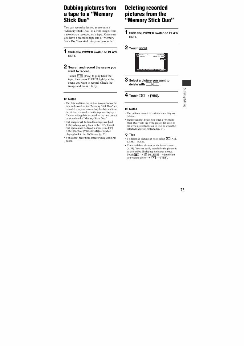
7/18/2019 SONY+HVR-HD1000 SERVICE MANUAL
http://slidepdf.com/reader/full/sonyhvr-hd1000-service-manual 354/42557
U s i n g t h e M e n u
You can add special effects to a pictureduring recording or playback. appears.
B OFF
Does not use [PICT.EFFECT] setting.
SKINTONE*
Makes skin texture look more smootherand more appealing.
NEG.ART
The color and brightness are reversed.
SEPIA
Pictures appear in sepia.
B&W (Black and white)
Pictures appear in black and white.
SOLARIZE
Pictures appear as an illustration withstrong contrast.
PASTEL*
Pictures appear as a pale pastel drawing.
MOSAIC*
Pictures appear mosaic-patterned.
b Notes
• Effects added to the playback pictures are not
output via the HDV/DV Interface (i.LINK).Only the original pictures can be output.
z Tips
• You can save pictures edited using specialeffects on a “Memory Stick Duo” (p. 73) or
record them on VCR or DVD/HDD recorders
(p. 68).
Fast moving subjects and actions, whichcannot be captured under general shootingconditions, can be shot in smooth movingslow-motion for about 3 seconds.This is useful to shoot fast actions such as a
golf or tennis swing.
Press START/STOP on the [SMTH SLWREC] screen.A 3 second-movie (approx.) is recorded as a12 second slow-motion movie.[Recording···] disappears, when recordingis finished.
Touch to set the following.
– [TIMING]Select the recording start point from the time
START/STOP is pressed (The default setting is[3sec AFTER]).
– [RECORD SOUND]
If you set to [ON] ( ), you can record
additional dialog, etc. to the slow-motion movie
(The default setting is [OFF]).
Sounds are recorded while [Recording···] is
displayed.
b Notes
• Sounds cannot be recorded while shooting a 3
second-movie (approx.).
PICT.EFFECT (Picture effect)
* Available during tape recording only.
SMTH SLW REC (Smooth slowrecording)
[3sec AFTER]
[3sec BEFORE]
Continued,
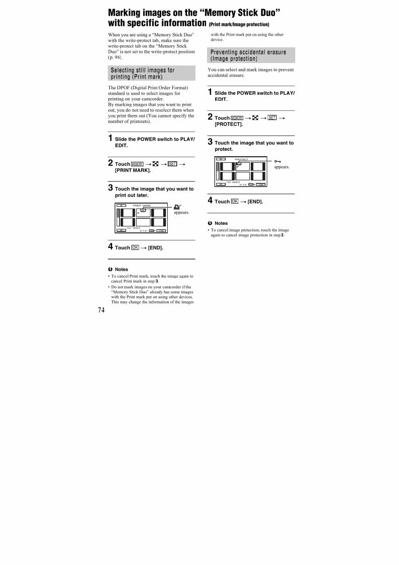
7/18/2019 SONY+HVR-HD1000 SERVICE MANUAL
http://slidepdf.com/reader/full/sonyhvr-hd1000-service-manual 355/42558
• The image quality of [SMTH SLW REC] is
somewhat less than normal recording.
To cancel [SMTH SLW REC], select[END].
See page 75.
You can connect the camcorder to a personal computer with a USB cable andimport pictures to the computer. You canalso connect the camcorder to a PictBridgecompatible printer (p. 75) using thisfunction.
B Memory Stick
Select this to view pictures on a “MemoryStick Duo” on the computer or to importthem to the computer.
PictBridge PRINT
Select this when you connect thecamcorder to a PictBridge compatible printer to print out directly (p. 75).
PictBridge PRINT
USB SELECT
EDIT/PLAY menuSettings for editing or playing back in
various modes
See page 42 for details on selectingmenu items.
You can play back in various modes whileviewing movies.
1 Touch the following buttons during playback.
2 Toucht
.To return to the normal playback mode,touch (Play/Pause) twice (once fromframe playback).
b Notes
• You will not hear the recorded sound. You may
see mosaic-like images of the previously played picture.
• Pictures in the HDV format are not output from
the HDV/DV Interface (i.LINK) when theyare paused or played back in any mode other
than normal playback mode.
• Pictures in the HDV format may appear
distorted during:
VAR.SPD PB(Various speed playback)
To Touch
change the
playback
direction* (frame)
play back
slowly** To reverse direction:
(frame)t
play back frame
by frame
(frame) during
playback pause.
To reverse direction:(frame) during
frame playback.
* Horizontal lines may appear at the top,
bottom, or in the center of the screen. Thisis not a malfunction.
**Pictures output from the HDV/DVInterface (i.LINK) cannot be played back
smoothly in slow mode.
PICT.APPLI. menu (Continued)
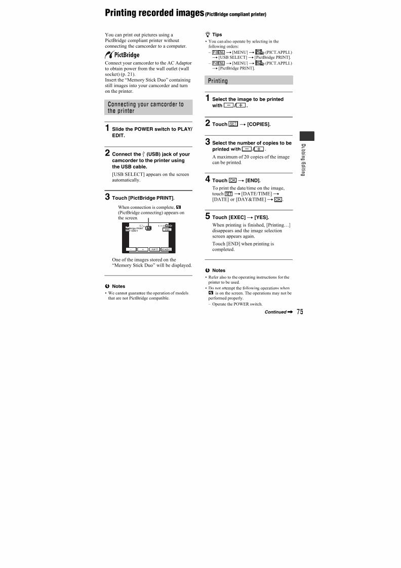
7/18/2019 SONY+HVR-HD1000 SERVICE MANUAL
http://slidepdf.com/reader/full/sonyhvr-hd1000-service-manual 356/42559
U s i n g t h e M e n u
– Picture search
– Reverse playback
• Playing back slowly to the reverse direction and
playing back frame by frame to the reverse
direction are not available in HDV format.
See page 71.
EXEC
The most recently recorded picture is played back for about 5 seconds and thenstops automatically.
CANCEL
Stops [END SEARCH].
b Notes
• [END SEARCH] will not work once you ejectthe cassette after you have recorded on the tape.
REC CTRL(Movie recording control)
END SEARCH
STANDARD SET menu
Settings while recording on a tape or other
basic settings
The default settings are marked with B.The indicators in parentheses appear when
the items are selected.See page 42 for details on selectingmenu items.
Select the playback signal. Normally select[AUTO].When your camcorder is connected toanother device using an i.LINK cable,
select the signal to input/output from theHDV/DV Interface (i.LINK). The selectedsignal is recorded or played back.
B AUTO
Switches the signals between HDV andDV format automatically when playing back a tape.
With an i.LINK connection, switches thesignals between HDV and DV formatsautomatically, and inputs/outputs from the
HDV/DV Interface (i.LINK).
HDV
Plays back only the portions recorded inHDV format.
With an i.LINK connection, inputs/outputsonly HDV formatted signals from theHDV/DV Interface (i.LINK), and records/ plays back. You can also select this whenconnecting the camcorder to a computer,
etc.DV
Plays back only the portions recorded inDV format.
With an i.LINK connection, inputs/outputsonly DV formatted signals from theHDV/DV Interface (i.LINK), and records/ plays back. You can also select this whenconnecting the camcorder to a computer,etc.
b Notes
• Disconnect the i.LINK cable before changing
the [VCR HDV/DV] setting. Otherwise, theconnected device, such as a VCR, may not be
VCR HDV/DV
Continued,

7/18/2019 SONY+HVR-HD1000 SERVICE MANUAL
http://slidepdf.com/reader/full/sonyhvr-hd1000-service-manual 357/42560
able to recognize the video signal from your
camcorder.
• When [AUTO] is selected, if the signal switches
between HDV and DV formats, the picture and
sound are interrupted temporarily.• When [i.LINK CONV] is set to
[ON:SQUEEZE]/[ON:EDGE CROP], pictures
are output as follows:
– at [AUTO], an HDV signal is converted to the
DV format and output; a DV signal is outputas it is.
– at [HDV], an HDV signal is converted to the
DV format and output; a DV signal is not
output.
– at [DV], a DV signal is output as it is; an
HDV signal is not output.
You can select a recording format.
B HDV1080i ( )
Records in the HDV1080i specification.
DV ( )
Records in the DV format.
b Notes
• If you output the recording picture using ani.LINK cable, set [i.LINK CONV] accordingly.
The following functions are available whenrecording in DV format.
x REC MODE (Recording mode)B SP ( SP )
Records in the SP (Standard Play) mode ona cassette.
LP ( LP )
Increases the recording time to 1.5 timesthe SP mode (Long Play).
b Notes
• If you record in the LP mode, pictures mayappear mosaic-like or sound may be interrupted
when you play back the tape on other
camcorders or VCRs.• When you mix recordings in the SP mode and in
the LP mode on one tape, the playback picture
may be distorted or the time code may not be
written properly between the scenes.
x WIDE SELECT
You can select the aspect ratio accordingto the TV connected when recording. Referalso to the instruction manuals suppliedwith your TV.
B 16:9 WIDE
Records pictures in the full screen for a16:9 (wide) TV screen.
4:3 ( )
Records pictures in the full screen for a 4:3TV screen.
b Notes
• Set [VIDEO OUT] correctly according to the
TV connected for playback.
x AUDIO MODE
B 12BIT
Records in the 12-bit mode (2 stereosounds).
16BIT ( )
Records in the 16-bit mode (1 stereo soundwith high quality).
b Notes
• When recording in the HDV format, sound is
automatically recorded in [16BIT] mode.
x AUDIO MIXDuring tape playback, you can monitor thesound recorded by other camcorders usingaudio dubbing or 4ch microphonerecording.
REC FORMAT
DV SET
STANDARD SET menu (Continued)
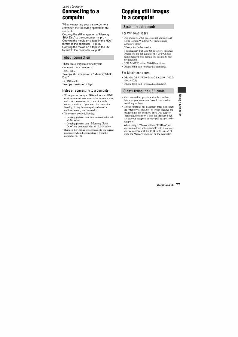
7/18/2019 SONY+HVR-HD1000 SERVICE MANUAL
http://slidepdf.com/reader/full/sonyhvr-hd1000-service-manual 358/42561
U s i n g t h e M e n u
Touch / to adjust the balance of theoriginal sound (ST1) and the soundrecorded afterwards (ST2), then touch .
b Notes
• The original sound (ST1) is output at the default
setting.
Touch / to adjust the volume(p. 33).
You can adjust the recording sound levelmanually.
B AUTO
Select to adjust the recording sound levelautomatically.
MANUAL
When the MIC LEVEL is set toMANUAL, the icon is displayed.
Touch / to adjust the recordingsound level during recording or standby.
The recording sound level adjustment bars
appear on the screen. The recording soundlevel increases as the bar goes to the right.The recording level meter appears whenthe recording sound level is other thandefault setting.
b Notes
• Use headphones to monitor the sound when
adjusting it.
Since the default setting is [ON], the audiolevel meter is displayed.
The recorded picture will not be affected bythis operation.
x LCD BRIGHTYou can adjust the brightness of the LCDscreen.
1 Adjust the brightness with / .
2 Touch .
x LCD BL LEVELYou can adjust the brightness of the LCDscreen’s backlight.
B NORMAL
Standard brightness.
BRIGHT
Brightens the LCD screen.
b Notes• When you connect your camcorder to outside
power sources, [BRIGHT] is automatically
selected for the setting.
• When you select [BRIGHT], battery life is
slightly reduced during recording.
x LCD COLORYou can adjust the color on the LCD screenwith / .
VOLUME
MIC LEVEL
AUDIO MIX
0:00:00:0060min
ST1 ST2
M
AU.LVL DISP (Audio level display)
LCD/VF SET
Audio level meter
Low intensity High intensity
Continued,
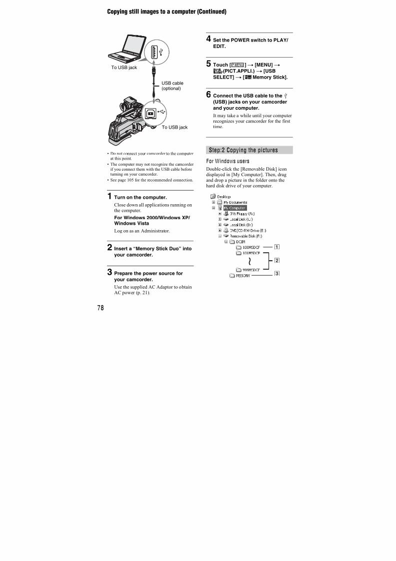
7/18/2019 SONY+HVR-HD1000 SERVICE MANUAL
http://slidepdf.com/reader/full/sonyhvr-hd1000-service-manual 359/42562
x VF B.LIGHTYou can adjust the brightness of theviewfinder.
BNORMALStandard brightness.
BRIGHT
Brightens the viewfinder screen.
x VF COLOR
B ON
Display pictures in the viewfinder in color.
OFF
Display pictures in the viewfinder in blackand white.
b Notes
• When you connect your camcorder to outside
power sources, [BRIGHT] is automatically
selected for the setting.
• When you select [BRIGHT], battery life is
slightly reduced during recording.
Select [COMPONENT] when connectingyour camcorder to a TV with thecomponent input jack.
576i
Select when connecting your camcorder toa TV with the component input jack.
B 1080i/576i
Select when connecting your camcorder toa TV that has the component input jackand is capable of displaying the 1080isignal.
You can set an output video signal typefrom HDV format signals.
xi.LINK CONVWhen set to [ON:SQUEEZE]/[ON:EDGE
CROP], converts the HDV signal to the DVformat and output it from the HDV/DV
Interface (i.LINK). The DV format signal isoutput unchanged.
B OFF
ON:SQUEZEOutput signals to a 16:9 wide TV or a TVcompatible with 16:9 wide mode.
ON:EDGE CROP
Display the center of the picture in 4:3aspect ratio by cropping the both sides ofthe picture.
b Notes
• For an i.LINK input, refer to “VCR HDV/DV”
(p. 59).
• Be sure to disconnect the i.LINK cable before
changing the setting. Otherwise, the connected
device may not be able to recognize the videosignal properly.
x VIDEO OUTYou can set the HDV output format for thefollowing outputs.
– COMPONENT (576i)
– S VIDEO
– AUDIO/VIDEO
B SQUEZE
Output signals to a 16:9 wide TV or a TVcompatible with 16:9 wide mode.
COMPONENT
DOWN CONVERT
On a 4:3 TVcompatible with16:9 wide modeOn a 16:9 wide TV
On a 4:3standard TV
STANDARD SET SET menu (Continued)
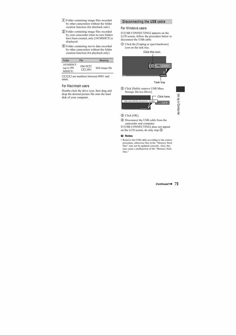
7/18/2019 SONY+HVR-HD1000 SERVICE MANUAL
http://slidepdf.com/reader/full/sonyhvr-hd1000-service-manual 360/42563
U s i n g t h e M e n u
LETTER BOX
Output signals to a TV that is notcompatible with 16:9 wide mode.
EDGE CROP
Display the center of the picture in 4:3aspect ratio by cropping the both sides ofthe picture.
b Notes
• When you view pictures that were recorded in
the DV format with [ WIDE SELECT] set to
[16:9 WIDE] on a 4:3 standard TV, picturesmay appear as they are in height, but are
compressed in width depending on the TV. If
you view the recorded pictures on such type of
4:3 standard TV, set [ WIDE SELECT] to[4:3] before recording.
You can check the setup value of thefollowing items.
OUTPUT
– [VCR HDV/DV](when the POWER switch isset to PLAY/EDIT) (p. 59)
– [COMPONENT] (p.64)
– [i.LINK CONV] (p. 62)
– [VIDEO OUT] (p. 62)
– HDMI OUT (p. 107)
HOURS METERThe cumulative operation time of yourcamcorder will be displayed with the totalhours of operation, drum rotation, taperunning, or the total number of tapeunthreading operations.
– OPERATION
Displays the total hours of operation in 10-hour increments.
– DRUM RUNDisplays the total hours of drum rotation in10-hour increments.
– TAPE RUN
Display the total hours of tape running in10-hour increments.
– THREADING
Displays the total number of tapeunthreading operations in 10-operation
increments.
You can display the frame and check thatthe subject is horizontal or vertical bysetting [GUIDEFRAME] to [ON].The frame is not recorded. Press DISPLAY/BATT INFO to make the frame disappear.
z Tips
• Placing the subject at the cross point of the
guide frame makes a balanced composition.
You can display the color bar or record it onthe tape by setting [COLOR BAR] to [ON].It is convenient to adjust the color on themonitor connected.
STATUS CHECK
On a 4:3 TVcompatible with16:9 wide modeOn a 16:9 wide TV
On a 4:3standard TV
On a 4:3standard TV
GUIDEFRAME
COLOR BAR
Continued,
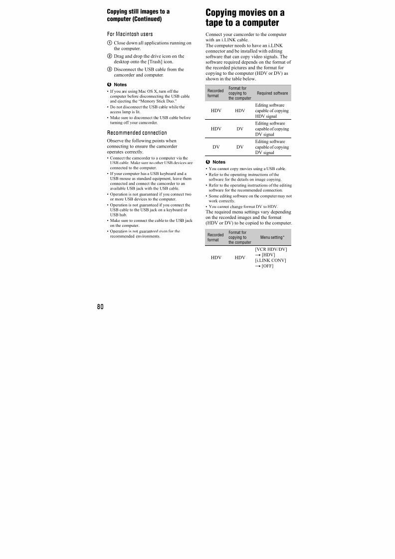
7/18/2019 SONY+HVR-HD1000 SERVICE MANUAL
http://slidepdf.com/reader/full/sonyhvr-hd1000-service-manual 361/42564
During playback, displays the information(data code) recorded automatically at thetime of recording.
B OFF
Data code is not displayed.
DATE/TIME
Displays the date and time.
CAMERA DATA (below)
Displays camera setting data.
A SteadyShot off
B Exposure
C White balance
D GainE Shutter speed
F Aperture value
b Notes
• The exposure adjustment value (0EV), a shutter
speed, and the aperture value appear when still
images on a “Memory Stick Duo” are played back.
• In the DATE/TIME data display, the date and
time are displayed in the same area. If you
record a picture without setting the clock, [-- ------] and [--:--:--] will appear.
B AUTO
Displays the remaining tape indicator forabout 8 seconds in situations such as thosedescribed below.
• When you set the POWER switch to PLAY/
EDIT or TAPE with a cassette inserted.• When you touch (Play/Pause).
ON
Always displays the remaining tapeindicator.
The camera recording lamp will not light upduring recording when you set this to [OFF](The default setting is [ON]).
B ON
A beeping sound starts when you start/stoprecording, or operate the touch panel.
OFF
Cancels the beeping sound and shuttersound.
B LCD PANEL
Shows displays such as the time code onthe LCD screen and in the viewfinder.
V-OUT/PANELShows displays such as the time code onthe TV screen, LCD screen, and in theviewfinder.
B NORMAL
Scrolls the menu items downwards bytouching .
OPPOSITE
Scrolls the menu items upwards bytouching .
See page 102.
You can slightly reduce the recording start point time when you start recording by
DATA CODE
REMAINING
0:00:00:0060min
AWB1009dBF1. 8
AUTO
P-MENU
60min 12
3
456
REC LAMP (Recording lamp)
BEEP
DISP OUTPUT (Display output)
MENU ROTATE
CALIBRATION
QUICK REC (Quick recording)
STANDARD SET menu (Continued)
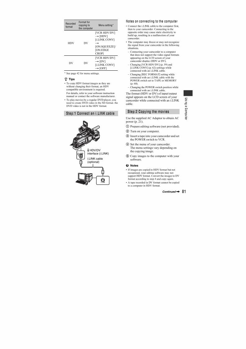
7/18/2019 SONY+HVR-HD1000 SERVICE MANUAL
http://slidepdf.com/reader/full/sonyhvr-hd1000-service-manual 362/42565
U s i n g t h e M e n u
pressing START/STOP. This function isuseful to compensate for time lapse at theclick of the shutter.
BOFFTakes more time to reach the recordingstart point, but a smooth transition can berecorded.
ON ( )
Slightly reduces the time it takes to startrecording when you attempt to record rightafter you switch on the camcorder (set thePOWER switch to TAPE from the OFF(CHG) position), or when you attempt to
record when the recording stanby mode iscanceled.
b Notes
• If [QUICK REC] is set to [ON], the interval
between scenes freezes for a moment (editing on
your computer is recommended).
z Tips
• If the recording standby mode continues more
than approximately 3 minutes, the drum will
stop rolling, and the standby mode is canceled.This is to protect the tape and to prevent from
unnecessarily battery exhausting.
TIME/LANGU.menuSee page 42 for details on selectingmenu items.
See page 24.
When using your camcorder abroad, youcan set the time difference by touching
/ , the clock will be adjusted inaccordance with the time difference.If you set the time difference to 0, the clock
returns to the originally set time.
You can select the language to be used onthe LCD screen.
• Your camcorder offers [ENG[SIMP]]
(simplified English) for when you cannot find
your native tongue among the options.
CLOCK SET
WORLD TIME
LANGUAGE
7/18/2019 SONY+HVR-HD1000 SERVICE MANUAL
http://slidepdf.com/reader/full/sonyhvr-hd1000-service-manual 363/42566
Customizing PersonalMenuYou can add desired menu items to anyPersonal Menu, and customize PersonalMenu settings for each POWER switch
position. This is convenient if you add
frequently used menu items to PersonalMenu.
You can add up to 28 menu items for eachPOWER switch position. Delete a lessimportant menu item, if you want to addmore.
1 Touch t [P-MENU SET UP]
t [ADD].
If the desired menu item is notdisplayed, touch / .
2 Touch / to select a menu
category, then touch .
3 Touch / to select a menu
item, then touch t [YES]t
.
The menu item is added to the end ofthe list.
Adding a menu item
OK
END
0:00:0060min
Select the category.
CAMERA SET
PICT.APPLI.EDIT/PLAY
STANDARD SETTIME/LANGU.
STBY
OK
END
0:00:0060min
Select the item.
SCENE SELECT
SPOT METER
EXPOSUREWHITE BAL.
SHARPNESS
STBY
1 Touch t [P-MENU SET UP]t [DELETE].
If the desired menu item is notdisplayed, touch / .
2 Touch the menu item that you
want to delete.
3 Touch [YES]t .
b Notes
• You cannot delete [MENU] and [P-MENU SET
UP].
Deleting a menu item
Select button to delete.
1/3
0:00:0060min
END
STBY
MENUSTATUS
CHECK
RING
SETL
WHITE
BAL.ZEBRA
MIC
LEVEL
Delete this fromCAMERA-TAPE mode's
P-MENU?
DELETE
YES NO
0:00:0060min STBY
7/18/2019 SONY+HVR-HD1000 SERVICE MANUAL
http://slidepdf.com/reader/full/sonyhvr-hd1000-service-manual 364/42567
U s i n g t h e M e n u
1 Touch t [P-MENU SET UP]
t [SORT].
If the desired menu item is notdisplayed, touch / .
2 Touch the menu item you want to
move.
3 Touch / to move the menu
item to the desired place.
4 Touch .
To sort more items, repeat steps 2 to 4.
5 Touch [END] t .
b Notes
• You cannot move [P-MENU SET UP].
Touch t [P-MENU SET UP]t
[RESET] t [YES] t [YES]t .
If the desired menu item is not displayed,touch / .
Arranging the order of menuitems displayed on PersonalMenu
Initializing the Personal Menusettings (Reset)
7/18/2019 SONY+HVR-HD1000 SERVICE MANUAL
http://slidepdf.com/reader/full/sonyhvr-hd1000-service-manual 365/42568
Dubbing/Editing
Dubbing to VCR or DVD/HDD recorders
Connect your camcorder to the wall outlet (wall socket) using the supplied AC Adaptor forthis operation (p. 21). Refer also to the instruction manuals supplied with the devices to beconnected.
The connection method and the image quality will differ depending on the VCR or DVD/HDD recorders and the connectors used.
Connecting to external devices
: Signal flow
Camcorder Cable External device
* An i.LINK jack which is compatible with HDV1080i specification is required. For details, refer to the
instruction manuals supplied with the device to be connected.
** When connecting your camcorder to a monaural device, connect the yellow plug of the A/V connecting
cable to the video jack on the device, and the white (left channel) or red (right channel) plug to the audio
jack on the device.
i.LINK cable (optional)HDV1080i compatibledevice*
t HD quality
i.LINK cable (optional)AV device with i.LINK jackt SD quality
A/V connecting cable with
S VIDEO (optional)
(Yellow)
(White)
(Red)
AV device with S VIDEO jackt
SD quality
A/V connecting cable(supplied)
(Yellow)(White)
(Red)
AV device with audio/video jacks**t SD quality
7/18/2019 SONY+HVR-HD1000 SERVICE MANUAL
http://slidepdf.com/reader/full/sonyhvr-hd1000-service-manual 366/42569
D u b b i n g / E d
i t i n g
b Notes
• You cannot dub pictures using the HDMI cable.
• Pictures recorded in the DV format are dubbed
as SD (standard definition) images, regardless
of the connection.
Jacks on your camcorder
Open the jack cover and connect the cable.
Using an i.LINK cable (optional)
Select the required settings from the table below and make the menu settings.
b Notes
• Disconnect the i.LINK cable before changing
these menu settings, otherwise the VCR or
DVD/HDD recorders may not correctly identifythe video signal.
b Notes
• When [VCR HDV/DV] is set to [AUTO], and
the signal switches between HDV and DV
formats, the picture and sound are interruptedtemporarily.
• When the player and the recorder are both
HDV1080i compatible devices such asHVR-HD1000E/HD1000P and are connected
with the i.LINK cable, after pausing or stopping
and then resuming the recording, the imageswill be unstable or rough at that point.
• Set [DISP OUTPUT] to [LCD PANEL] (defaultsetting) when connecting with an A/V
connecting cable (p. 64).
When connecting with the A/Vconnecting cable with an S VIDEO(optional)
Connect with S VIDEO jack instead of thevideo plug (yellow). This connection
produces pictures more faithfully. Theaudio will not be output when you connectwith the S VIDEO cable alone.
Recordedformat
Dubbingformat
Menu setting
[VCRHDV/DV]
[i.LINKCONV]
HDV
only
HDV*1[AUTO]
or HDV[OFF]
DV [AUTO]
[ON:
SQUEEZE]/
[ON:
EDGE
CROP]
Mixed
HDV
and DV
HDV*1 [AUTO]or
HDV*2
[OFF]
DV [AUTO]*3
[ON:
SQUEEZE]/
[ON:
EDGE
CROP]
DV only DV[AUTO]
or DV –
*1 The VCR or DVD/HDD recorders need to be
compliant with HDV1080i specification.
*2 Parts recorded in DV format cannot be dubbed.
*3 Parts recorded in both DV and HDV format can
be dubbed.
Recordedformat
Dubbingformat
Menu setting
[VCRHDV/DV]
[i.LINKCONV]
Continued,
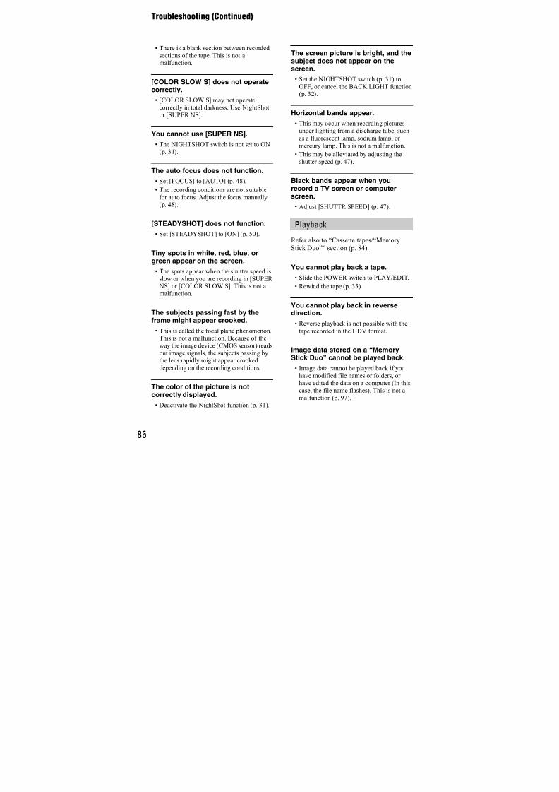
7/18/2019 SONY+HVR-HD1000 SERVICE MANUAL
http://slidepdf.com/reader/full/sonyhvr-hd1000-service-manual 367/42570
1 Prepare your camcorder forplayback.
Insert the recorded cassette.Slide the POWER switch to PLAY/EDIT.
2 When dubbing to the VCR, insert
a cassette for recording.
When dubbing to the DVDrecorder, insert a DVD for
recording.
If your recording device has an inputselector, set it to the appropriate input(such as video input1 and video input2).
3 Connect your recording device
(VCR or DVD/HDD recorder) toyour camcorder.
See page 68 for connection details.
4 Start playback on your
camcorder, and recording on the
recording device.
Refer to the operating instructions
supplied with your recording device fordetails.
5 When dubbing is complete, stop
your camcorder and the
recording device.
b Notes
• When connecting with an A/V connecting cable,
set [VIDEO OUT] according to the playback
device (TV, etc.).
• To record the date/time and camera settings data
when connected by the A/V connecting cable,
display them on the screen (p. 64).
• The following cannot be output via the HDV/
DV interface (i.LINK): – Indicators
– Pictures edited with [PICT.EFFECT] (p. 57)or [D.EFFECT] (p. 56)
– Titles that are recorded on other camcorders
• Pictures recorded in the HDV format are not
output from the HDV/DV Interface (i.LINK)
during playback pause or in any playback mode
other than normal playback.
• Note the following when connecting with an
i.LINK cable:
– The recorded picture becomes rough when a
picture is paused on your camcorder while
recording to a VCR or DVD/HDD recorder.
– Data codes (date/time/camera settings data)
may not be displayed or recorded dependingon the device or application.
– You cannot record the picture and soundseparately.
• When dubbing to a DVD recorder from your
camcorder through an i.LINK cable, you may
not operate your camcorder on your DVDrecorder even if its instruction manual says you
can.
If you can set the input mode to HDV or DV on
your DVD recorder and can input/output pictures, follow the steps in “Dubbing to another
device.”
• When you use an i.LINK cable, the video and
sound signals are transmitted digitally,
producing high quality pictures.
• When an i.LINK cable is connected, the format
of the output signal ( or) will be indicated on the LCD screen of
your camcorder.
Dubbing to another device
Dubbing to VCR or DVD/HDD recorders (Continued)
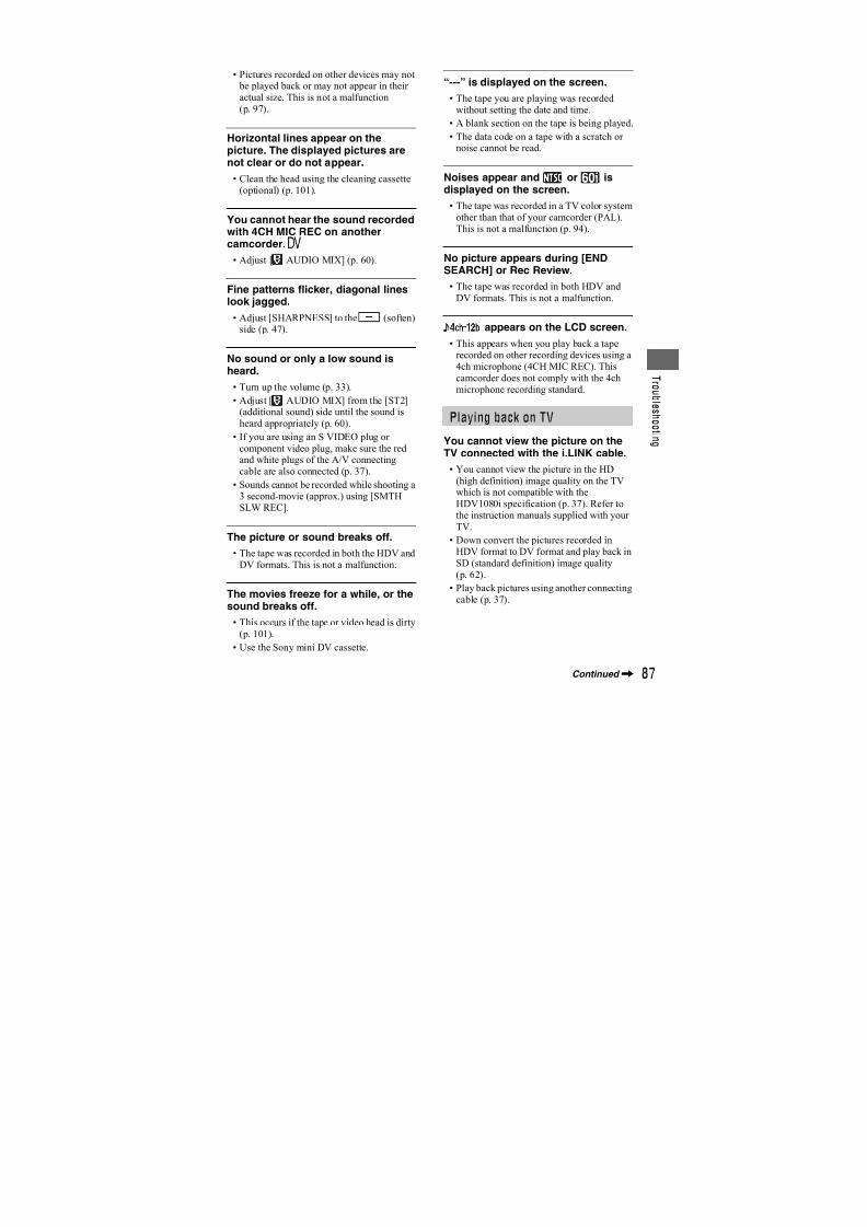
7/18/2019 SONY+HVR-HD1000 SERVICE MANUAL
http://slidepdf.com/reader/full/sonyhvr-hd1000-service-manual 368/42571
D u b b i n g / E d
i t i n g
Recording pictures from a VCR
You can record movies from a VCR on atape. You can record a scene as a still imageon a “Memory Stick Duo.” Be sure to inserta cassette or a “Memory Stick Duo” for
recording in your camcorder beforehand.You can connect your camcorder to a VCRdevice using an i.LINK cable.Connect your camcorder to the wall outlet(wall socket) using the supplied ACAdaptor for this operation (p. 21). Referalso to the instruction manuals suppliedwith the devices to be connected.
* An i.LINK jack which is compatible with
HDV1080i specification is required.
1 Slide the POWER switch to PLAY/ EDIT.
2 Set the input signal of your
camcorder.
Set [VCR HDV/DV] to [AUTO] whenrecording from an HDV formatcompatible device.
Set [VCR HDV/DV] to [DV] or[AUTO] when recording from a DVformat compatible device (p. 59).
3 Connect your VCR as a player to
your camcorder.
b Notes
• When an i.LINK cable is connected, theformat of the input signal (or ) will be indicated on the
LCD screen of your camcorder (This
indicator may appear on the screen of the playback device, however, it will not be
recorded).
4 Insert a cassette into the VCR.
5 Operate your camcorder to record
movies.
Touch t [ REC CTRL]t [REC PAUSE].
If the desired item is not displayed onthe screen, touch / until the itemis displayed.
HDV1080i
compatible device
AV device with
i.LINK output jack
t HD quality t SD quality
To i.LINK connector
i.LINK cable(optional)
To HDV/DV
Interface(i.LINK)
: Signalflow
Recording movies
Continued,
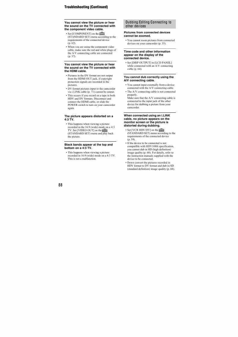
7/18/2019 SONY+HVR-HD1000 SERVICE MANUAL
http://slidepdf.com/reader/full/sonyhvr-hd1000-service-manual 369/42572
6 Start playing the cassette on your
VCR.
The picture played on the connecteddevice appears on the LCD screen ofyour camcorder.
7 Touch [REC START] at the point
you want to start recording.
8 Stop recording.
Touch (Stop) or [REC PAUSE].
9 Touch t .
b Notes
• You need an i.LINK cable for this operation.
• You cannot record TV programs from theHDV/DV Interface (i.LINK).
• You can record pictures from DV devices onlyin the DV format.
• Note the following when connecting with ani.LINK cable:
– The recorded picture becomes rough when a picture is paused on a VCR while recording to
your camcorder.
– You cannot record the picture and sound
separately.
– If you pause or stop the recording and restartit, the picture may not be recorded smoothly.
• When a 4:3 video signal is input, it appears with
black bands on the right and left sides on the
screen of your camcorder.
1Perform steps 1 to 4 in
“Recording movies”.
2 Start playing the cassette.
The pictures on the VCR appear on thescreen of your camcorder.
3Press PHOTO lightly at the scene
you want to record. Check the
image and press it fully.
Recording still images
Recording pictures from a VCR (Continued)
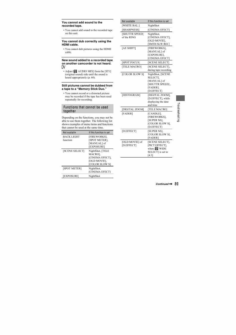
7/18/2019 SONY+HVR-HD1000 SERVICE MANUAL
http://slidepdf.com/reader/full/sonyhvr-hd1000-service-manual 370/42573
D u b b i n g / E d
i t i n g
Dubbing pictures froma tape to a “MemoryStick Duo”You can record a desired scene onto a“Memory Stick Duo” as a still image, from
a movie you recorded on a tape. Make sureyou have a recorded tape and a “MemoryStick Duo” inserted into your camcorder.
1 Slide the POWER switch to PLAY/
EDIT.
2Search and record the scene you
want to record.
Touch (Play) to play back thetape, then press PHOTO lightly at thescene you want to record. Check theimage and press it fully.
b Notes
• The date and time the picture is recorded on thetape and stored on the “Memory Stick Duo” arerecorded. On your camcorder, the date and time
the picture is recorded on the tape are displayed.
Camera setting data recorded on the tape cannot be stored on the “Memory Stick Duo.”
• Still images will be fixed to image size [
1.2M] when playing back in the HDV format.Still images will be fixed to image size [
0.2M] (16:9) or [VGA (0.3M)] (4:3) when
playing back in the DV format (p. 53).
• You cannot record still images while using PBzoom.
Deleting recordedpictures from the“Memory Stick Duo”
1 Slide the POWER switch to PLAY/ EDIT.
2 Touch .
3 Select a picture you want to
delete with / .
4 Touch t [YES].
b Notes
• The pictures cannot be restored once they are
deleted.
• Pictures cannot be deleted when a “Memory
Stick Duo” with the write-protect tab is set to
the write-protect position (p. 96), or when the
selected picture is protected (p. 74).
z Tips
• To delete all pictures at once, select [ ALLERASE] (p. 53).
• You can delete pictures on the index screen
(p. 34). You can easily search for the picture to be deleted by displaying 6 pictures at once.
Touch t [ DELETE]t the picture
you want to deletet t [YES].
1011/10101 –0001
1– 1
60
minin
P-MENU
MEMORY PLAYEMORY PLAY
MEMORY PLAY6.1M60min
101 –0001

7/18/2019 SONY+HVR-HD1000 SERVICE MANUAL
http://slidepdf.com/reader/full/sonyhvr-hd1000-service-manual 371/42574
Marking images on the “Memory Stick Duo”with specific information (Print mark/Image protection)
When you are using a “Memory Stick Duo”with the write-protect tab, make sure thewrite-protect tab on the “Memory StickDuo” is not set to the write-protect position
(p. 96).
The DPOF (Digital Print Order Format)standard is used to select images for
printing on your camcorder.By marking images that you want to printout, you do not need to reselect them whenyou print them out (You cannot specify thenumber of printouts).
1 Slide the POWER switch to PLAY/
EDIT.
2 Touch t t t
[PRINT MARK].
3 Touch the image that you want to
print out later.
4 Touch t [END].
b Notes
• To cancel Print mark, touch the image again to
cancel Print mark in step 3.• Do not mark images on your camcorder if the
“Memory Stick Duo” already has some imageswith the Print mark put on using other devices.
This may change the information of the images
with the Print mark put on using the other
device.
You can select and mark images to preventaccidental erasure.
1 Slide the POWER switch to PLAY/
EDIT.
2 Touch t t t
[PROTECT].
3 Touch the image that you want to
protect.
4 Touch t [END].
b Notes• To cancel image protection, touch the image
again to cancel image protection in step3.
Selecting still images forprinting (Print mark)
2/10
PRINT MARK
101–0002101 OK
appears.
Preventing accidental erasure(Image protection)
2/10101–000 2
PROTECT
101 OK
-
appears.
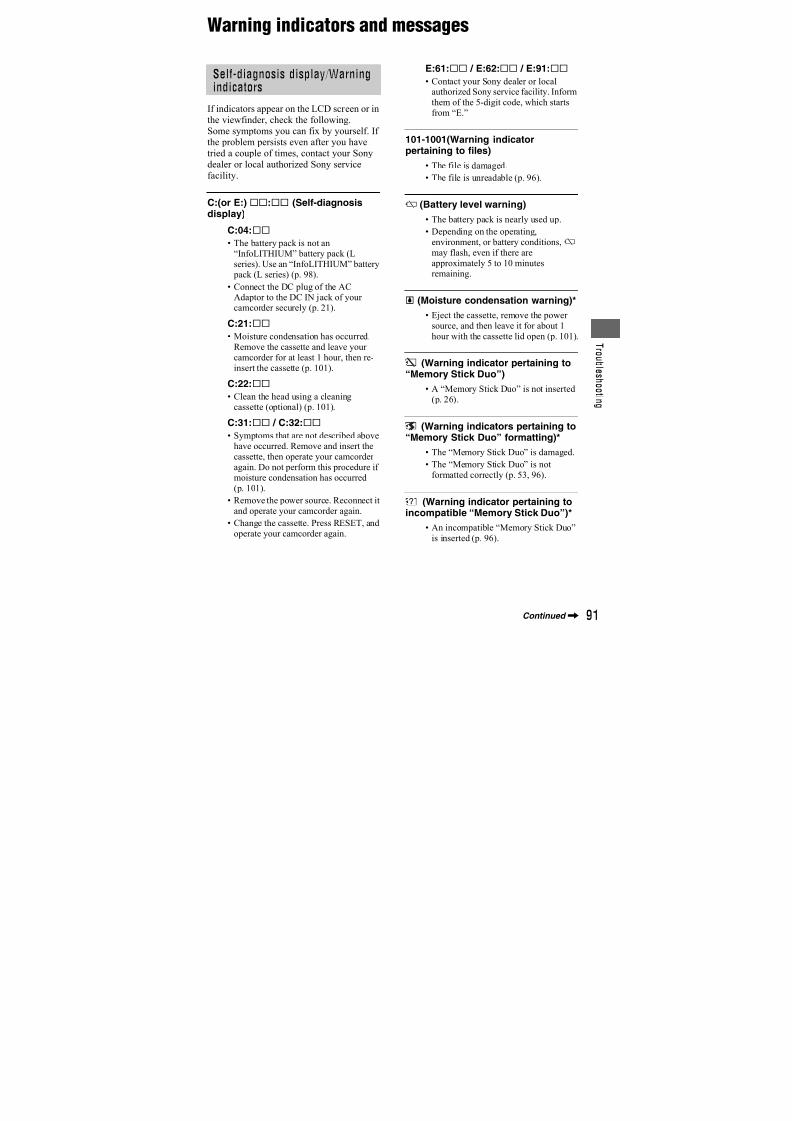
7/18/2019 SONY+HVR-HD1000 SERVICE MANUAL
http://slidepdf.com/reader/full/sonyhvr-hd1000-service-manual 372/42575
D u b b i n g / E d
i t i n g
Printing recorded images (PictBridge compliant printer)
You can print out pictures using aPictBridge compliant printer withoutconnecting the camcorder to a computer.
Connect your camcorder to the AC Adaptorto obtain power from the wall outlet (wallsocket) (p. 21).Insert the “Memory Stick Duo” containingstill images into your camcorder and turnon the printer.
1 Slide the POWER switch to PLAY/
EDIT.
2 Connect the (USB) jack of your
camcorder to the printer using
the USB cable.
[USB SELECT] appears on the screenautomatically.
3 Touch [PictBridge PRINT].
One of the images stored on the“Memory Stick Duo” will be displayed.
b Notes
• We cannot guarantee the operation of models
that are not PictBridge compatible.
z Tips
• You can also operate by selecting in the
following orders:
– t [MENU]t (PICT.APPLI.)
t [USB SELECT]t [PictBridge PRINT]. – t [MENU]t (PICT.APPLI.)
t [PictBridge PRINT].
1 Select the image to be printed
with / .
2 Touch t [COPIES].
3 Select the number of copies to be
printed with / .
A maximum of 20 copies of the imagecan be printed.
4 Touch t [END].
To print the date/time on the image,touch t [DATE/TIME]t [DATE] or [DAY&TIME]t .
5 Touch [EXEC]t [YES].
When printing is finished, [Printing…]disappears and the image selectionscreen appears again.
Touch [END] when printing iscompleted.
b Notes
• Refer also to the operating instructions for the
printer to be used.• Do not attempt the following operations when
is on the screen. The operations may not be
performed properly.
– Operate the POWER switch.
Connecting your camcorder to
the printer
101-0001 1 1
SET+-
1011/10
END
6.1M
EXEC
101-0001
PictBridge PRINTict ridge PRINTPictBridge PRINT
When connection is complete,(PictBridge connecting) appears onthe screen.
Printing
Continued,
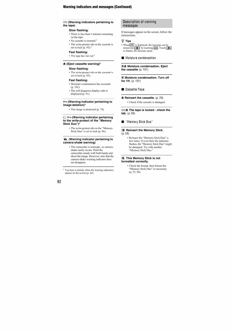
7/18/2019 SONY+HVR-HD1000 SERVICE MANUAL
http://slidepdf.com/reader/full/sonyhvr-hd1000-service-manual 373/42576
– Disconnect the USB cable from the printer.
– Remove the “Memory Stick Duo” from your
camcorder.
• If the printer stops working, disconnect the USB
cable, turn the printer off and on again andrestart the operation from the beginning.
• Some printers may cut off left, right, top andlower parts of the image. Especially, when the
image is recorded with a 16:9 (wide) ratio, left
and right parts may be largely cut off.
• Some printer models may not support the date/
time printing function. Refer to your printer’s
operating instructions for details.
• We cannot guarantee the printing of images
recorded with a device other than your
camcorder.• PictBridge is an industry standard established
by the Camera & Imaging Products Association
(CIPA). You can print still images without usinga computer by connecting a printer directly to a
digital video camera or digital still camera,
regardless of model or manufacturer.
Printing recorded images (PictBridge compliant printer) (Continued)
7/18/2019 SONY+HVR-HD1000 SERVICE MANUAL
http://slidepdf.com/reader/full/sonyhvr-hd1000-service-manual 374/42577
U s i n
g a C o m p u t e r
Using a Computer
Connecting to acomputerWhen connecting your camcorder to acomputer, the following operations areavailable:
Copying the still images on a “MemoryStick Duo” to the computer t p. 77
Copying the movie on a tape in the HDVformat to the computer t p. 80Copying the movie on a tape in the DVformat to the computer t p. 80
There are 2 ways to connect your
camcorder to a computer: – USB cable
To copy still images on a “Memory StickDuo”
– i.LINK cable
To copy movies on a tape
Notes on connecting to a computer
• When you are using a USB cable or an i.LINK
cable to connect your camcorder to a computer,
make sure to connect the connector in thecorrect direction. If you insert the connectorforcibly, it may be damaged, and cause a
malfunction of your camcorder.
• You cannot do the following:
– Copying pictures on a tape to a computer witha USB cable.
– Copying pictures on a “Memory StickDuo” to a computer with an i.LINK cable.
• Remove the USB cable according to the correct
procedure when disconnecting it from the
computer (p. 79).
Copying still imagesto a computer
For Windows users• OS: Windows 2000 Professional/Windows XP
Home Edition/Windows XP Professional/
Windows Vista*
* Except for 64-bit version
It is necessary that your OS is factory-installed.Operations are not guaranteed if your OS has
been upgraded or is being used in a multi-boot
environment.
• CPU: MMX Pentium 200MHz or faster
• Others: USB port (provided as standard).
For Macintosh users
• OS: Mac OS 9.1/9.2 or Mac OS X (v10.1/v10.2/
v10.3/v10.4)
• Others: USB port (provided as standard).
• You can do this operation with the standard
driver on your computer. You do not need toinstall any software.
• If your computer has a Memory Stick slot, insertthe “Memory Stick Duo” on which pictures are
recorded into the Memory Stick Duo adaptor
(optional), then insert it into the Memory Stickslot on your computer to copy still images to the
computer.
• When using a “Memory Stick PRO Duo” and
your computer is not compatible with it, connect
your camcorder with the USB cable instead of
using the Memory Stick slot on the computer.
About connection
System requirements
Step:1 Using the USB cable
Continued,
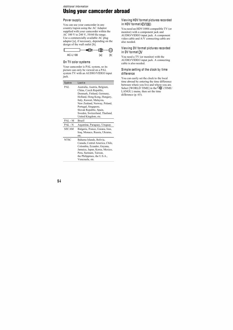
7/18/2019 SONY+HVR-HD1000 SERVICE MANUAL
http://slidepdf.com/reader/full/sonyhvr-hd1000-service-manual 375/42578
• Do not connect your camcorder to the computer
at this point.
• The computer may not recognize the camcorder
if you connect them with the USB cable beforeturning on your camcorder.
• See page 105 for the recommended connection.
1 Turn on the computer.
Close down all applications running onthe computer.
For Windows 2000/Windows XP/
Windows VistaLog on as an Administrator.
2 Insert a “Memory Stick Duo” into
your camcorder.
3 Prepare the power source for
your camcorder.Use the supplied AC Adaptor to obtainAC power (p. 21).
4 Set the POWER switch to PLAY/
EDIT.
5 Touch [ ]t [MENU] t
(PICT.APPLI.) t [USB
SELECT] t [ Memory Stick].
6 Connect the USB cable to the
(USB) jacks on your camcorder
and your computer.
It may take a while until your computerrecognizes your camcorder for the firsttime.
For Windows users
Double-click the [Removable Disk] icondisplayed in [My Computer]. Then, dragand drop a picture in the folder onto thehard disk drive of your computer.
To USB jack
USB cable(optional)
To USB jack
Step:2 Copying the pictures
1
2
3
Copying still images to a computer (Continued)
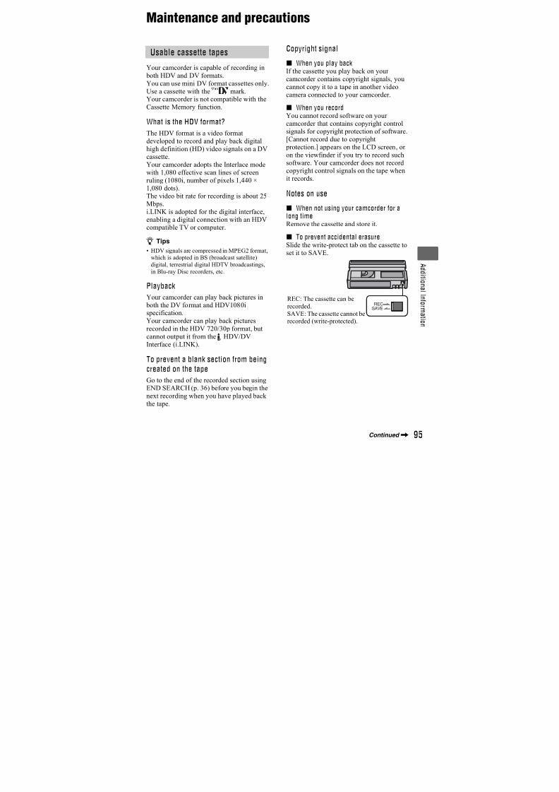
7/18/2019 SONY+HVR-HD1000 SERVICE MANUAL
http://slidepdf.com/reader/full/sonyhvr-hd1000-service-manual 376/42579
U s i n
g a C o m p u t e r
A Folder containing image files recorded by other camcorders without the foldercreation function (for playback only).
B Folder containing image files recorded by your camcorder when no new foldershave been created, only [101MSDCF] isdisplayed.
C Folder containing movie data recorded by other camcorders without the foldercreation function (for playback only)
ssss are numbers between 0001 and9999.
For Macintosh users
Double-click the drive icon, then drag anddrop the desired picture file onto the harddisk of your computer.
For Windows users
If [USB CONNECTING] appears on theLCD screen, follow the procedure below todisconnect the USB cable.
1 Click the [Unplug or eject hardware]icon on the task tray.
2 Click [Safely remove USB MassStorage Device-Drive].
3 Click [OK].
4 Disconnect the USB cable from thecamcorder and computer.
If [USB CONNECTING] does not appearon the LCD screen, do only step4.
b Notes
• Remove the USB cable according to the correct
procedure, otherwise files in the “Memory Stick
Duo” may not be updated correctly. Also, this
may cause a malfunction of the “Memory Stick
Duo.”
Folder File Meaning
101MSDCF
(up to 999
MSDCF)
DSC0ssss.JPG
Still image file
Disconnecting the USB cable
Click this icon.
Task tray
Click here.
Continued,
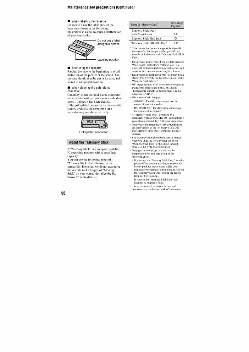
7/18/2019 SONY+HVR-HD1000 SERVICE MANUAL
http://slidepdf.com/reader/full/sonyhvr-hd1000-service-manual 377/42580
For Macintosh users
1 Close down all applications running onthe computer.
2 Drag and drop the drive icon on thedesktop onto the [Trash] icon.
3 Disconnect the USB cable from thecamcorder and computer.
b Notes
• If you are using Mac OS X, turn off the
computer before disconnecting the USB cableand ejecting the “Memory Stick Duo.”
• Do not disconnect the USB cable while the
access lamp is lit.• Make sure to disconnect the USB cable before
turning off your camcorder.
Recommended connection
Observe the following points whenconnecting to ensure the camcorderoperates correctly.
• Connect the camcorder to a computer via theUSB cable. Make sure no other USB devices are
connected to the computer.• If your computer has a USB keyboard and a
USB mouse as standard equipment, leave them
connected and connect the camcorder to an
available USB jack with the USB cable.
• Operation is not guaranteed if you connect twoor more USB devices to the computer.
• Operation is not guaranteed if you connect theUSB cable to the USB jack on a keyboard or
USB hub.
• Make sure to connect the cable to the USB jack
on the computer.
• Operation is not guaranteed even for the
recommended environments.
Copying movies on atape to a computerConnect your camcorder to the computerwith an i.LINK cable.The computer needs to have an i.LINKconnector and be installed with editing
software that can copy video signals. Thesoftware required depends on the format ofthe recorded pictures and the format forcopying to the computer (HDV or DV) asshown in the table below.
b Notes
• You cannot copy movies using a USB cable.
• Refer to the operating instructions of thesoftware for the details on image copying.
• Refer to the operating instructions of the editing
software for the recommended connection.
• Some editing software on the computer may not
work correctly.
• You cannot change format DV to HDV.
The required menu settings vary dependingon the recorded images and the format
(HDV or DV) to be copied to the computer.
Recordedformat
Format forcopying tothe computer
Required software
HDV HDV
Editing software
capable of copyingHDV signal
HDV DV
Editing software
capable of copying
DV signal
DV DVEditing software
capable of copying
DV signal
Recordedformat
Format forcopying tothe computer
Menu setting*
HDV HDV
[VCR HDV/DV]
t [HDV]
[i.LINK CONV]
t [OFF]
Copying still images to a
computer (Continued)
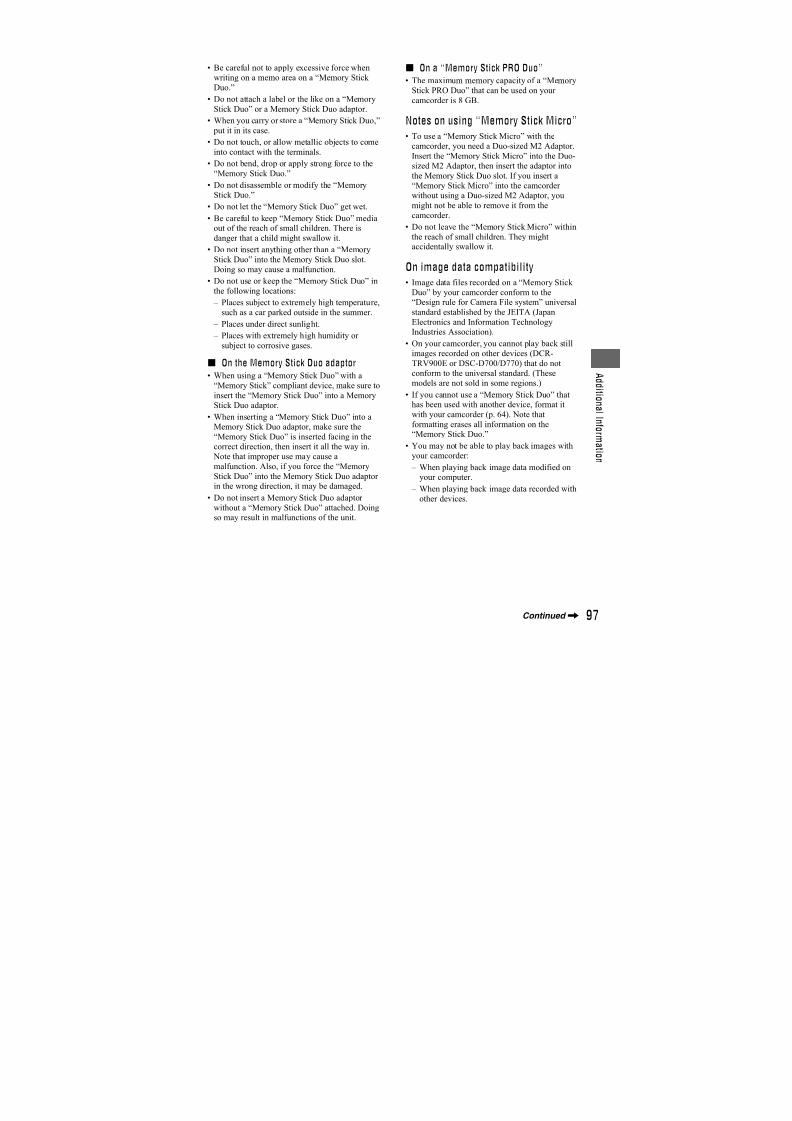
7/18/2019 SONY+HVR-HD1000 SERVICE MANUAL
http://slidepdf.com/reader/full/sonyhvr-hd1000-service-manual 378/42581
U s i n
g a C o m p u t e r
* See page 42 for menu settings.
z Tips
• To copy HDV format images as they are
without changing their format, an HDV
compatible environment is required.
For details, refer to your software instructionmanual or contact the software manufacturer.
• To play movies by a regular DVD player, youneed to create DVD video in the SD format. the
DVD video is not in the HDV format.
Notes on connecting to the computer
• Connect the i.LINK cable to the computer first,
then to your camcorder. Connecting in the
opposite order may cause static electricity to
build up, resulting in a malfunction of yourcamcorder.
• The computer may freeze or may not recognize
the signal from your camcorder in the following
situations.
– Connecting your camcorder to a computerthat does not support the video signal formats
appearing on the LCD screen of your
camcorder display (HDV or DV).
– Changing [VCR HDV/DV] (p. 59) and
[i.LINK CONV] (p. 62) settings whileconnected with an i.LINK cable.
– Changing [REC FORMAT] setting while
connected with an i.LINK cable with the
POWER switch set to TAPE or MEMORY
(p. 60).
– Changing the POWER switch position while
connected with an i.LINK cable.
The format (HDV or DV) of input/outputsignal appears on the LCD screen of yourcamcorder while connected with an i.LINK
cable.
Use the supplied AC Adaptor to obtain AC power (p. 21).
1 Prepare editing software (not provided).
2 Turn on your computer.
3 Insert a tape into your camcorder and set
the POWER switch to VCR.
4 Set the menu of your camcorder.The menu settings vary depending onthe copying image.
5 Copy images to the computer with yoursoftware.
b Notes
• If images are copied in HDV format but not
recognized, your editing software may notsupport HDV format. Convert the images to DV
format according to step 4 and copy again.
• A tape recorded in DV format cannot be copied
to a computer in HDV format.
HDV DV
[VCR HDV/DV]
t [HDV]
[i.LINK CONV]
t
[ON:SQUEEZE]/
[ON:EDGE
CROP]
DV DV
[VCR HDV/DV]
t [DV]
[i.LINK CONV]
t [OFF]
Step:1 Connect an i.LINK cable
Recordedformat
Format forcopying tothe computer
Menu setting*
HDV/DVinterface (i.LINK)
i.LINK cable(optional)
Step:2 Copying the movies
Continued,
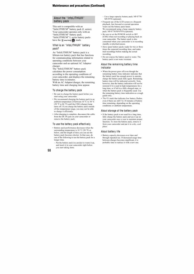
7/18/2019 SONY+HVR-HD1000 SERVICE MANUAL
http://slidepdf.com/reader/full/sonyhvr-hd1000-service-manual 379/42582
z Tips
• When images recorded in HDV format arecopied to a computer, the file size is about 2GB
(almost the same as a DV file) for a 10-minute
movie if the video compression format isMPEG2.
When copying the movie in the HDVformat from the computer to yourcamcorder
Set [VCR HDV/DV] to [HDV] and [i.LINKCONV] to [OFF] (p. 59).
b Notes
• To copy an HDV format movie edited on a
computer back onto a tape in HDV format is
possible so long as your editing softwaresupports copying HDV movies onto tape. For
details, contact the software manufacturer.
When copying the movie in the DVformat from the computer to yourcamcorder
Set [VCR HDV/DV] to [DV] (p. 59).
Copying movies on a tape to a computer (Continued)
7/18/2019 SONY+HVR-HD1000 SERVICE MANUAL
http://slidepdf.com/reader/full/sonyhvr-hd1000-service-manual 380/42583
T r o u b l e s h o o t i n g
Troubleshooting
Troubleshooting
If you run into any problems using yourcamcorder, use the following table totroubleshoot the problem. If the problem
persists, disconnect the power source and
contact your Sony dealer.
• Overall operations .................................83
• Batteries/Power sources ........................83
• LCD screen/viewfinder .........................84
• Cassette tapes/“Memory Stick Duo”.....84
• Recording ..............................................85
• Playback................................................86
• Playing back on TV...............................87
• Dubbing/Editing/Connecting to otherdevices...................................................88
• Functions that cannot be used together ...............................................................89
The power does not turn on.
• Attach a charged battery pack to thecamcorder (p. 21).
• Use the AC Adaptor to connect to a walloutlet (wall socket) (p. 21).
The camcorder does not operateeven when the power is set to on.
• Disconnect the AC Adaptor from the walloutlet (wall socket) or remove the battery pack, then reconnect it after about 1 minute.
• Press the RESET button using a sharp-
pointed object (If you press the RESET button, all settings are reset, exceptPersonal Menu items).
The camcorder gets warm.
• The camcorder may get warmer while youuse it. This is not a malfunction.
The power abruptly turns off.
• Charge the battery pack (p. 21).
The CHG (charge) lamp does notlight while the battery pack is beingcharged.
• Slide the POWER switch to OFF (CHG)(p. 21).
• Attach the battery pack to the camcordercorrectly (p. 21).
• Connect the power cord (mains lead) to thewall outlet (wall socket) properly.
• The battery charge is completed (p. 21).
The CHG (charge) lamp flashes whilethe battery pack is being charged.
• Attach the battery pack to the camcordercorrectly (p. 21). If the problem persists,disconnect the AC Adaptor from the walloutlet (wall socket) and contact your Sonydealer. The battery pack may be damaged.
The remaining battery time indicatordoes not indicate the correct time.
• Ambient temperature is too high or too low,
or the battery pack has not been chargedenough. This is not a malfunction.
• Fully charge the battery again. If the problem persists, the battery may be worn-out. Replace it with a new one (p. 21, 98).
• The indicated time may not be correct incertain circumstances. For example, whenyou open or close the LCD panel, it takesabout 1 minute to display the correctremaining battery time.
The battery pack discharges tooquickly.
• Ambient temperature is too high or low, orthe battery pack has not been chargedenough. This is not a malfunction.
• Fully charge the battery again. If the problem persists, the battery may be worn-out. Replace it with a new one (p. 21, 98).
Overall operations
Batteries/Power sources
7/18/2019 SONY+HVR-HD1000 SERVICE MANUAL
http://slidepdf.com/reader/full/sonyhvr-hd1000-service-manual 381/42584
Menu items are grayed out.
• You cannot select grayed items in thecurrent recording/playback situation.
• Depending on the functions, you may not be able to use them together (p. 89).
You cannot turn off the indicator.
• You cannot turn off . Touch tocheck the warning messages (p. 92).
The buttons do not appear on thetouch panel.
• Touch the LCD screen lightly.
• Press DISPLAY/BATT INFO on yourcamcorder (p. 25).
The buttons on the touch panel donot work correctly or do not work atall.
• Adjust the touch panel ([CALIBRATION])(p. 102).
The picture in the viewfinder is notclear.
• Move the viewfinder lens adjustment leveruntil the picture appears clearly (p. 25).
The LCD screen does not turn on.
• Set the LCD ON/OFF switch to ON.
The cassette cannot be ejected fromthe compartment.
• Make sure the power source (battery packor AC Adaptor) is connected correctly(p. 21).
• Moisture condensation has occurred insidethe camcorder (p. 101).
The Cassette Memory indicator ortitle display does not appear while
using a cassette with CassetteMemory.
• This camcorder does not support CassetteMemory, so the indicator does not appear.
The remaining tape indicator is notdisplayed.
• Set [ REMAINING] to [ON] to alwaysdisplay the remaining tape indicator (p. 64).
The cassette is noisier duringrewinding or fast-forwarding.
• When using the AC Adaptor, rewind/fastforward speed increases (compared with battery operation) and therefore increasesnoise. This is not a malfunction.
You cannot operate functions using
a “Memory Stick Duo,” even if a“Memory Stick Duo” is inserted.
• Slide the POWER switch to MEMORY orPLAY/EDIT (p. 24).
• If you use a “Memory Stick Duo” formattedon a computer, format it again on yourcamcorder (p. 53).
You cannot delete the recorded
picture on the tape.• You cannot delete a recorded picture on
tape; you can only rewind the tape andrecord again. The new recording overwritesthe existing one.
LCD screen/viewfinder Cassette tapes/“Memory StickDuo”
Troubleshooting (Continued)
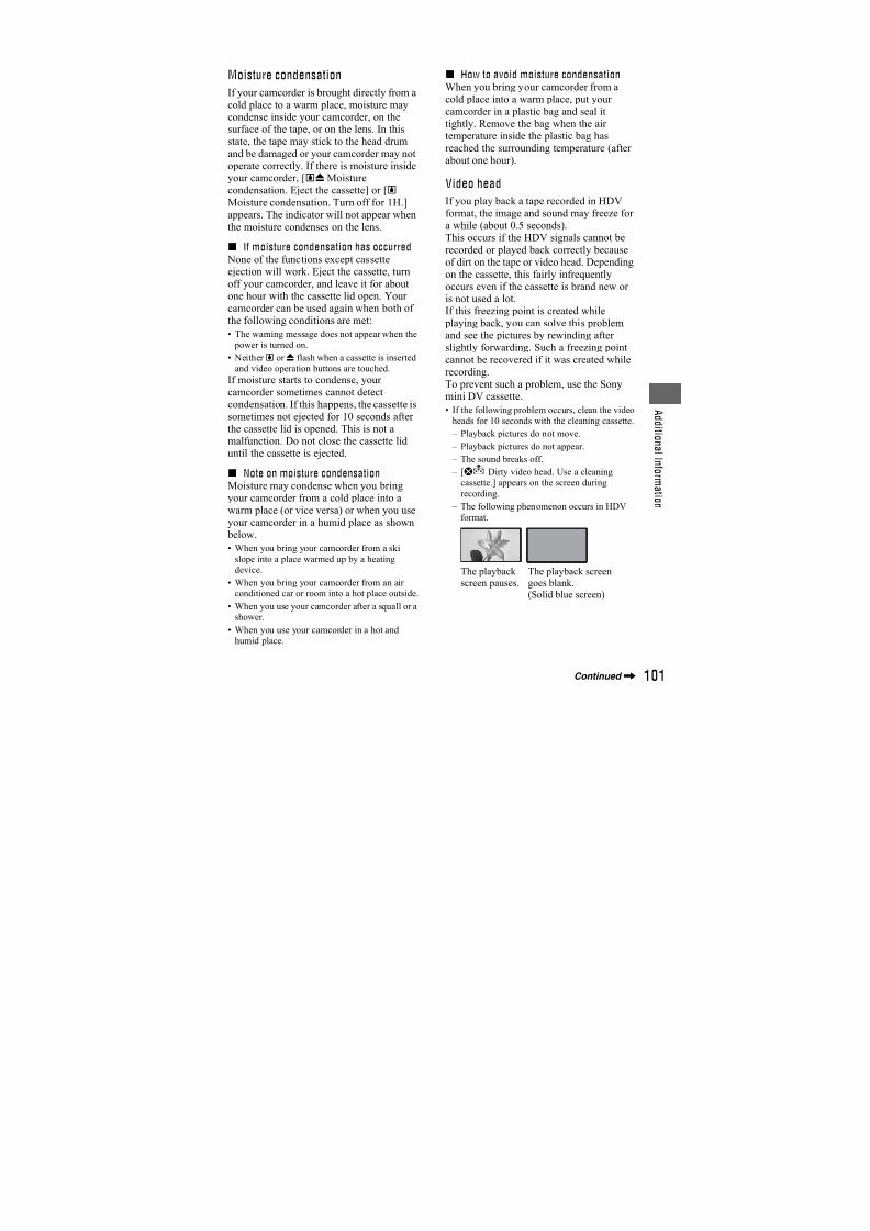
7/18/2019 SONY+HVR-HD1000 SERVICE MANUAL
http://slidepdf.com/reader/full/sonyhvr-hd1000-service-manual 382/42585
T r o u b l e s h o o t i n g
You cannot delete pictures or formata “Memory Stick Duo.”
• Cancel image protection on the picture
(p. 74).• The maximum number of pictures that you
can delete on the index screen at one time is100.
Image protection cannot be applied,or you cannot mark pictures forprint.
• Release the lock on the write-protect tab of
the “Memory Stick Duo” if there is one(p. 96).
• Perform the operation again on the indexscreen (p. 34, 74).
• The maximum number of pictures you canmark for print is 999.
The data file name is not indicatedcorrectly, or flashes.
• The file is damaged.
• Use the file format compatible with yourcamcorder (p. 96).
Refer also to “Cassette tapes/“MemoryStick Duo”” section (p. 84).
The tape does not start when you
press START/STOP.• Slide the POWER switch to TAPE (p. 28).
• The tape has reached the end. Rewind it, orinsert a new cassette.
• Set the write-protect tab to REC or insert anew cassette (p. 95).
• The tape is stuck to the drum due tomoisture condensation. Remove thecassette and leave your camcorder for atleast 1 hour, then reinsert the cassette
(p. 101).
You cannot record on the “MemoryStick Duo.”
• The “Memory Stick Duo” is full. Insert
another “Memory Stick Duo” or format the“Memory Stick Duo” (p. 53). Or, deleteunnecessary pictures recorded on the“Memory Stick Duo” (p. 73).
• When the POWER switch is set to TAPE,you cannot record still images on the“Memory Stick Duo” with: – When [SHUTTR SPEED] is set between
1/600 to 1/10000 second – While executing [FADER] – [D.EFFECT] – [PICT.EFFECT] – [SMTH SLW REC] – [COLOR BAR]
The recording image view looksdifferent.
• The recording image view may lookdifferent depending on the condition ofyour camcorder. This is not a malfunction.
You cannot record a smoothtransition on a tape from the lastrecorded scene to the next.
• Perform END SEARCH (p. 36).
• Do not remove the cassette (The picturewill be recorded continuously without a break even when you turn the power off).
• Do not record pictures in the HDV and DV
formats on the same tape.• Do not record pictures in SP mode and LPmode on the same tape.
• Avoid stopping then recording a movie inthe LP mode.
• When [QUICK REC] is set to [ON], youcannot record a smooth transition (p. 64).
[END SEARCH] does not work.
• Do not eject the cassette after recording(p. 36).
• There is nothing recorded on the cassette.
Recording
Continued,
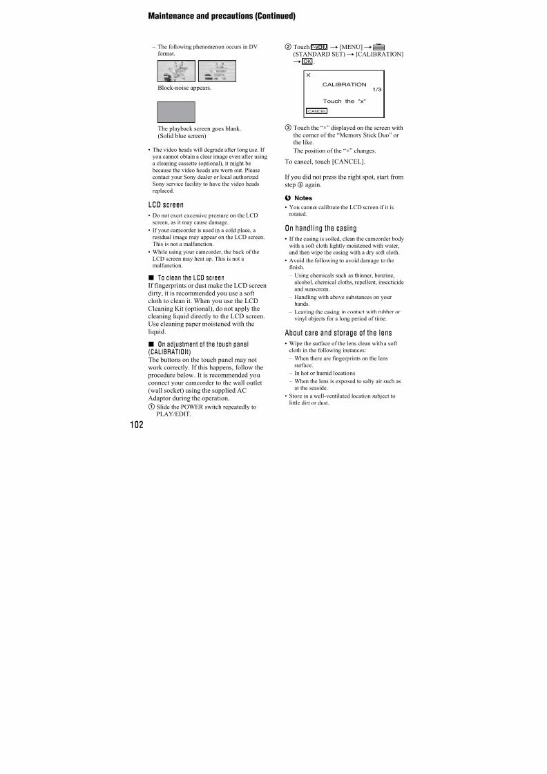
7/18/2019 SONY+HVR-HD1000 SERVICE MANUAL
http://slidepdf.com/reader/full/sonyhvr-hd1000-service-manual 383/42586
• There is a blank section between recordedsections of the tape. This is not amalfunction.
[COLOR SLOW S] does not operatecorrectly.
• [COLOR SLOW S] may not operatecorrectly in total darkness. Use NightShotor [SUPER NS].
You cannot use [SUPER NS].
• The NIGHTSHOT switch is not set to ON(p. 31).
The auto focus does not function.
• Set [FOCUS] to [AUTO] (p. 48).
• The recording conditions are not suitablefor auto focus. Adjust the focus manually(p. 48).
[STEADYSHOT] does not function.
• Set [STEADYSHOT] to [ON] (p. 50).
Tiny spots in white, red, blue, orgreen appear on the screen.
• The spots appear when the shutter speed isslow or when you are recording in [SUPER NS] or [COLOR SLOW S]. This is not amalfunction.
The subjects passing fast by theframe might appear crooked.
• This is called the focal plane phenomenon.This is not a malfunction. Because of theway the image device (CMOS sensor) readsout image signals, the subjects passing bythe lens rapidly might appear crookeddepending on the recording conditions.
The color of the picture is not
correctly displayed.• Deactivate the NightShot function (p. 31).
The screen picture is bright, and thesubject does not appear on thescreen.
• Set the NIGHTSHOT switch (p. 31) toOFF, or cancel the BACK LIGHT function(p. 32).
Horizontal bands appear.
• This may occur when recording picturesunder lighting from a discharge tube, suchas a fluorescent lamp, sodium lamp, ormercury lamp. This is not a malfunction.
• This may be alleviated by adjusting theshutter speed (p. 47).
Black bands appear when yourecord a TV screen or computerscreen.
• Adjust [SHUTTR SPEED] (p. 47).
Refer also to “Cassette tapes/“MemoryStick Duo”” section (p. 84).
You cannot play back a tape.
• Slide the POWER switch to PLAY/EDIT.
• Rewind the tape (p. 33).
You cannot play back in reverse
direction.• Reverse playback is not possible with the
tape recorded in the HDV format.
Image data stored on a “MemoryStick Duo” cannot be played back.
• Image data cannot be played back if youhave modified file names or folders, orhave edited the data on a computer (In thiscase, the file name flashes). This is not amalfunction (p. 97).
Playback
Troubleshooting (Continued)
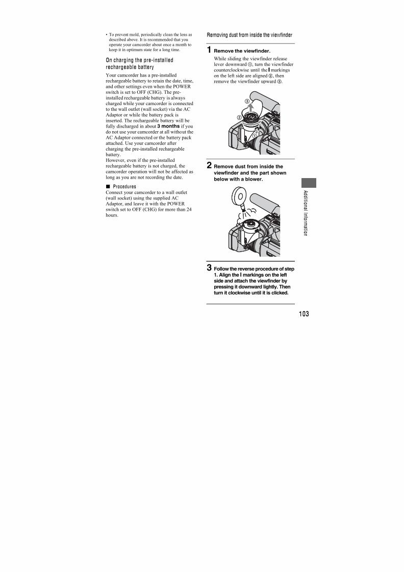
7/18/2019 SONY+HVR-HD1000 SERVICE MANUAL
http://slidepdf.com/reader/full/sonyhvr-hd1000-service-manual 384/42587
T r o u b l e s h o o t i n g
• Pictures recorded on other devices may not be played back or may not appear in theiractual size. This is not a malfunction(p. 97).
Horizontal lines appear on thepicture. The displayed pictures arenot clear or do not appear.
• Clean the head using the cleaning cassette(optional) (p. 101).
You cannot hear the sound recordedwith 4CH MIC REC on another
camcorder.• Adjust [ AUDIO MIX] (p. 60).
Fine patterns flicker, diagonal lineslook jagged.
• Adjust [SHARPNESS] to the (soften)side (p. 47).
No sound or only a low sound is
heard.
• Turn up the volume (p. 33).
• Adjust [ AUDIO MIX] from the [ST2](additional sound) side until the sound isheard appropriately (p. 60).
• If you are using an S VIDEO plug orcomponent video plug, make sure the redand white plugs of the A/V connectingcable are also connected (p. 37).
• Sounds cannot be recorded while shooting a3 second-movie (approx.) using [SMTHSLW REC].
The picture or sound breaks off.
• The tape was recorded in both the HDV andDV formats. This is not a malfunction.
The movies freeze for a while, or thesound breaks off.
• This occurs if the tape or video head is dirty(p. 101).
• Use the Sony mini DV cassette.
“---” is displayed on the screen.
• The tape you are playing was recordedwithout setting the date and time.
• A blank section on the tape is being played.• The data code on a tape with a scratch or
noise cannot be read.
Noises appear and or isdisplayed on the screen.
• The tape was recorded in a TV color systemother than that of your camcorder (PAL).This is not a malfunction (p. 94).
No picture appears during [ENDSEARCH] or Rec Review.
• The tape was recorded in both HDV andDV formats. This is not a malfunction.
appears on the LCD screen.
• This appears when you play back a taperecorded on other recording devices using a
4ch microphone (4CH MIC REC). Thiscamcorder does not comply with the 4chmicrophone recording standard.
You cannot view the picture on theTV connected with the i.LINK cable.
• You cannot view the picture in the HD(high definition) image quality on the TV
which is not compatible with theHDV1080i specification (p. 37). Refer tothe instruction manuals supplied with yourTV.
• Down convert the pictures recorded inHDV format to DV format and play back inSD (standard definition) image quality(p. 62).
• Play back pictures using another connectingcable (p. 37).
Playing back on TV
Continued,
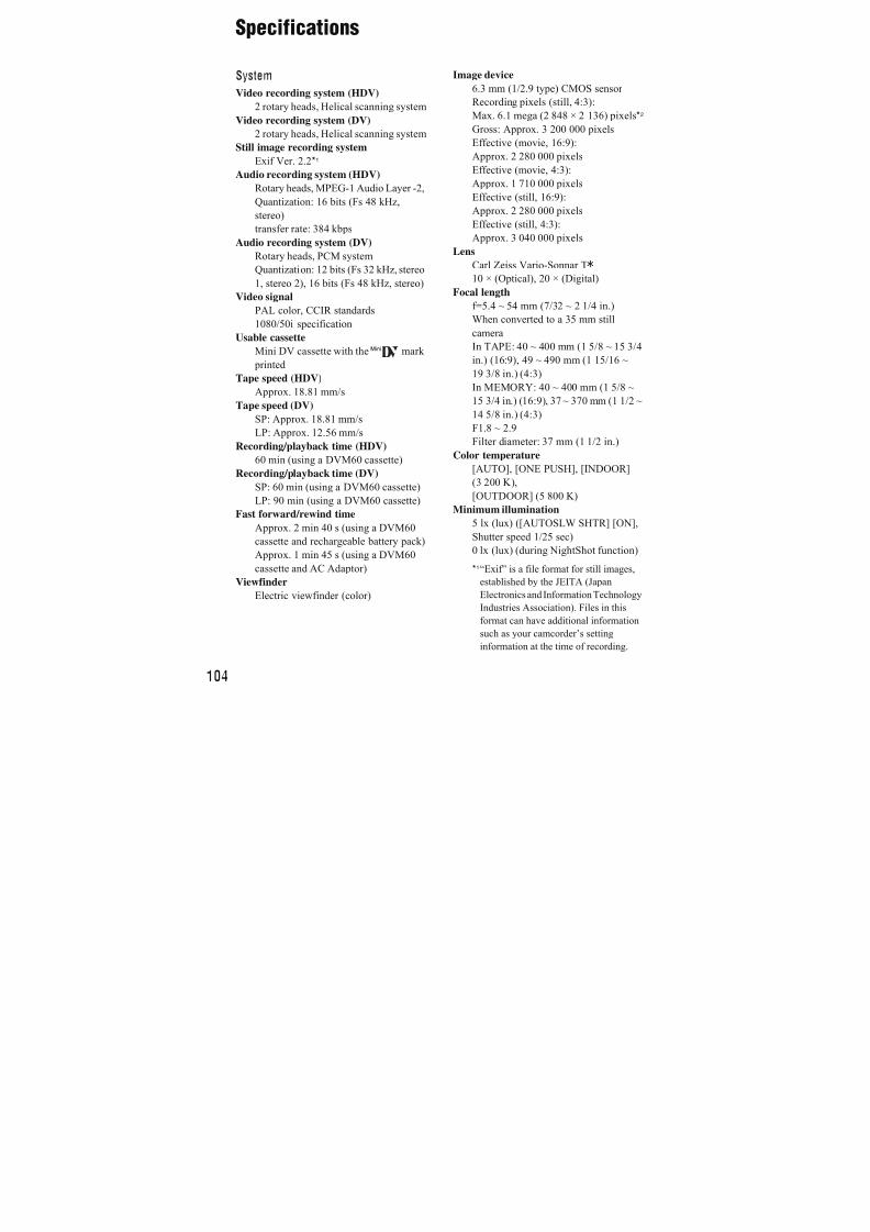
7/18/2019 SONY+HVR-HD1000 SERVICE MANUAL
http://slidepdf.com/reader/full/sonyhvr-hd1000-service-manual 385/42588
You cannot view the picture or hearthe sound on the TV connected withthe component video cable.
• Set [COMPONENT] on the(STANDARD SET) menu according to therequirements of the connected device(p. 62).
• When you are using the component videocable, make sure the red and white plugs ofthe A/V connecting cable are connected(p. 37).
You cannot view the picture or hear
the sound on the TV connected withthe HDMI cable.
• Pictures in the DV format are not outputfrom the HDMI OUT jack, if copyright protection signals are recorded in the pictures.
• DV format pictures input to the camcordervia i.LINK cable (p. 71) cannot be output.
• This occurs if you record on a tape in bothHDV and DV formats. Disconnect and
connect the HDMI cable, or slide thePOWER switch to turn on your camcorderagain.
The picture appears distorted on a4:3 TV.
• This happens when viewing a picturerecorded in the 16:9 (wide) mode on a 4:3TV. Set [VIDEO OUT] on the
(STANDARD SET) menu and play backthe picture.
Black bands appear at the top andbottom on a 4:3 TV.
• This happens when viewing a picturerecorded in 16:9 (wide) mode on a 4:3 TV.This is not a malfunction.
Pictures from connected devicescannot be zoomed.
• You cannot zoom pictures from connecteddevices on your camcorder (p. 35).
Time code and other informationappear on the display of theconnected device.
• Set [DISP OUTPUT] to [LCD PANEL]
while connected with an A/V connectingcable (p. 64).
You cannot dub correctly using theA/V connecting cable.
• You cannot input externally from a deviceconnected with the A/V connecting cable.
• The A/V connecting cable is not connected properly.Make sure that the A/V connecting cable is
connected to the input jack of the otherdevice for dubbing a picture from yourcamcorder.
When connected using an i.LINKcable, no picture appears on themonitor screen or the picture isdistorted during dubbing.
• Set [VCR HDV/DV] on the
(STANDARD SET) menu according to therequirements of the connected device(p. 59).
• If the device to be connected is notcompatible with HDV1080i specification,you cannot dub in HD (high definition)image quality (p. 68). For details, refer tothe instruction manuals supplied with thedevice to be connected.
• Down convert the pictures recorded inHDV format to DV format and dub in SD
(standard definition) image quality (p. 68).
Dubbing/Editing/Connecting toother devices
Troubleshooting (Continued)
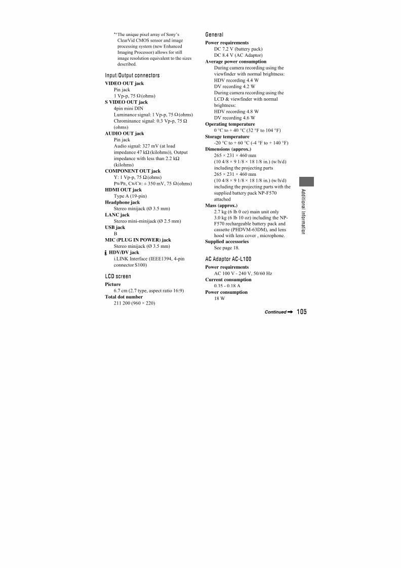
7/18/2019 SONY+HVR-HD1000 SERVICE MANUAL
http://slidepdf.com/reader/full/sonyhvr-hd1000-service-manual 386/42589
T r o u b l e s h o o t i n g
You cannot add sound to therecorded tape.
• You cannot add sound to the recorded tape
on this unit.
You cannot dub correctly using theHDMI cable.
• You cannot dub pictures using the HDMIcable.
New sound added to a recorded tapeon another camcorder is not heard.
• Adjust [ AUDIO MIX] from the [ST1](original sound) side until the sound isheard appropriately (p. 60).
Still pictures cannot be dubbed froma tape to a “Memory Stick Duo.”
• You cannot record or a distorted picturemay be recorded if the tape has been used
repeatedly for recording.
Depending on the functions, you may not beable to use them together. The following listshows examples of menu items and functionsthat cannot be used at the same time.
Functions that cannot be usedtogether
Not available If this function is setBACK LIGHT
function
[FIREWORKS],
[SPOT METER],
[MANUAL] of
[EXPOSURE]
[SCENE SELECT] NightShot, [TELE
MACRO],
[CINEMA EFECT],
[OLD MOVIE],
[COLOR SLOW S]
[SPOT METER] NightShot,
[CINEMA EFECT]
[EXPOSURE] NightShot
[WHITE BAL.] NightShot
[SHARPNESS] [CINEMA EFECT]
[SHUTTR SPEED]of the RING
NightShot,[CINEMA EFECT],
[OLD MOVIE],
[SMTH SLW REC]
[AE SHIFT] [FIREWORKS],
[MANUAL] of
[EXPOSURE],
[CINEMA EFECT]
[SPOT FOCUS] [SCENE SELECT]
[TELE MACRO] [SCENE SELECT],during tape recording
[COLOR SLOW S] NightShot, [SCENE
SELECT],
[MANUAL] of
[SHUTTR SPEED] ,
[FADER],
[D.EFFECT]
[HISTOGRAM] [DIGITAL ZOOM],
[D.EFFECT], while
displaying the date
and time
[DIGITAL ZOOM] [TELE MACRO]
[FADER] [CANDLE],
[FIREWORKS],
[SUPER NS],
[COLOR SLOW S],
[D.EFFECT]
[D.EFFECT] [SUPER NS],
[COLOR SLOW S],[FADER]
[OLD MOVIE] of
[D.EFFECT]
[SCENE SELECT],
[PICT.EFFECT],
when [ WIDE
SELECT] is set to
[4:3]
Not available If this function is set
Continued,
7/18/2019 SONY+HVR-HD1000 SERVICE MANUAL
http://slidepdf.com/reader/full/sonyhvr-hd1000-service-manual 387/42590
• When [COLOR BAR] is set, all the “Not
available” menu items on the list are not
available.
[CINEMA EFECT]
of [D.EFFECT]
[SCENE SELECT],
[SPOT METER],
[MANUAL] of[EXPOSURE], other
than 0 in [AE
SHIFT],
[PICT.EFFECT],
when [ WIDE
SELECT] is set to
[4:3]
[SMTH SLW REC] [CANDLE],
[FIREWORKS],
[MANUAL] of[SHUTTR SPEED] ,
[SUPER NS],
[COLOR SLOW S],
[D.EFFECT],
[PICT.EFFECT]
Not available If this function is set
Troubleshooting (Continued)
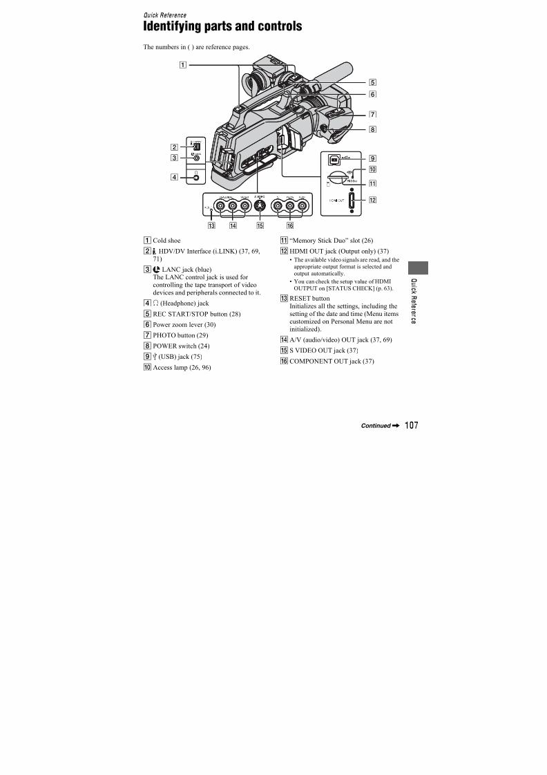
7/18/2019 SONY+HVR-HD1000 SERVICE MANUAL
http://slidepdf.com/reader/full/sonyhvr-hd1000-service-manual 388/42591
T r o u b l e s h o o t i n g
Warning indicators and messages
If indicators appear on the LCD screen or inthe viewfinder, check the following.Some symptoms you can fix by yourself. Ifthe problem persists even after you havetried a couple of times, contact your Sonydealer or local authorized Sony servicefacility.
C:(or E:) ss:ss (Self-diagnosisdisplay)
C:04:ss
• The battery pack is not an“InfoLITHIUM” battery pack (Lseries). Use an “InfoLITHIUM” battery pack (L series) (p. 98).
• Connect the DC plug of the ACAdaptor to the DC IN jack of yourcamcorder securely (p. 21).
C:21:ss
• Moisture condensation has occurred.Remove the cassette and leave yourcamcorder for at least 1 hour, then re-insert the cassette (p. 101).
C:22:ss
• Clean the head using a cleaningcassette (optional) (p. 101).
C:31:ss / C:32:ss
• Symptoms that are not described above
have occurred. Remove and insert thecassette, then operate your camcorderagain. Do not perform this procedure ifmoisture condensation has occurred(p. 101).
• Remove the power source. Reconnect itand operate your camcorder again.
• Change the cassette. Press RESET, andoperate your camcorder again.
E:61:ss / E:62:ss / E:91:ss
• Contact your Sony dealer or localauthorized Sony service facility. Informthem of the 5-digit code, which starts
from “E.”
101-1001(Warning indicatorpertaining to files)
• The file is damaged.
• The file is unreadable (p. 96).
E (Battery level warning)
• The battery pack is nearly used up.• Depending on the operating,
environment, or battery conditions,E may flash, even if there areapproximately 5 to 10 minutesremaining.
% (Moisture condensation warning)*
• Eject the cassette, remove the powersource, and then leave it for about 1
hour with the cassette lid open (p. 101).
(Warning indicator pertaining to“Memory Stick Duo”)
• A “Memory Stick Duo” is not inserted(p. 26).
(Warning indicators pertaining to“Memory Stick Duo” formatting)*
• The “Memory Stick Duo” is damaged.
• The “Memory Stick Duo” is notformatted correctly (p. 53, 96).
(Warning indicator pertaining toincompatible “Memory Stick Duo”)*
• An incompatible “Memory Stick Duo”is inserted (p. 96).
Self-diagnosis display/Warningindicators
Continued,
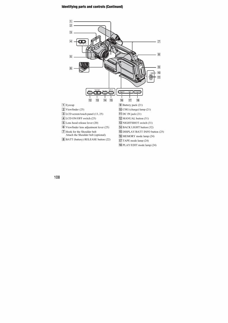
7/18/2019 SONY+HVR-HD1000 SERVICE MANUAL
http://slidepdf.com/reader/full/sonyhvr-hd1000-service-manual 389/42592
Q (Warning indicators pertaining tothe tape)
Slow flashing:
• There is less than 5 minutes remainingon the tape.
• No cassette is inserted.*
• The write-protect tab on the cassette isset to lock (p. 95).*
Fast flashing:
• The tape has run out.*
Z (Eject cassette warning)*
Slow flashing:
• The write-protect tab on the cassette isset to lock (p. 95).
Fast flashing:
• Moisture condensation has occurred(p. 101).
• The self-diagnosis display code isdisplayed (p. 91).
- (Warning indicator pertaining toimage deletion)*
• The image is protected (p. 74).
- (Warning indicator pertainingto the write-protect of the “MemoryStick Duo”)*
• The write-protect tab on the “Memory
Stick Duo” is set to lock (p. 96).
(Warning indicator pertaining tocamera-shake warning)
• The camcorder is unsteady, so camera-shake easily occurs. Hold thecamcorder steady with both hands andshoot the image. However, note that thecamera-shake warning indicator doesnot disappear.
* You hear a melody when the warning indicators
appear on the screen (p. 64).
If messages appear on the screen, follow theinstructions.
z Tips
• When is displayed, the message can beturned into by touching . Touch
to display the message again.
x Moisture condensation
%Z Moisture condensation. Ejectthe cassette (p. 101)
% Moisture condensation. Turn offfor 1H. (p. 101)
x Cassette/Tape
Z Reinsert the cassette. (p. 26)
• Check if the cassette is damaged.
QZ The tape is locked - check thetab. (p. 95)
x “Memory Stick Duo”
Reinsert the Memory Stick.(p. 26)
• Reinsert the “Memory Stick Duo” afew times. If even then the indicatorflashes, the “Memory Stick Duo” might be damaged. Try with another“Memory Stick Duo.”
This Memory Stick is notformatted correctly.
• Check the format, then format the“Memory Stick Duo” as necessary(p. 53, 96).
Description of warningmessages
Warning indicators and messages (Continued)
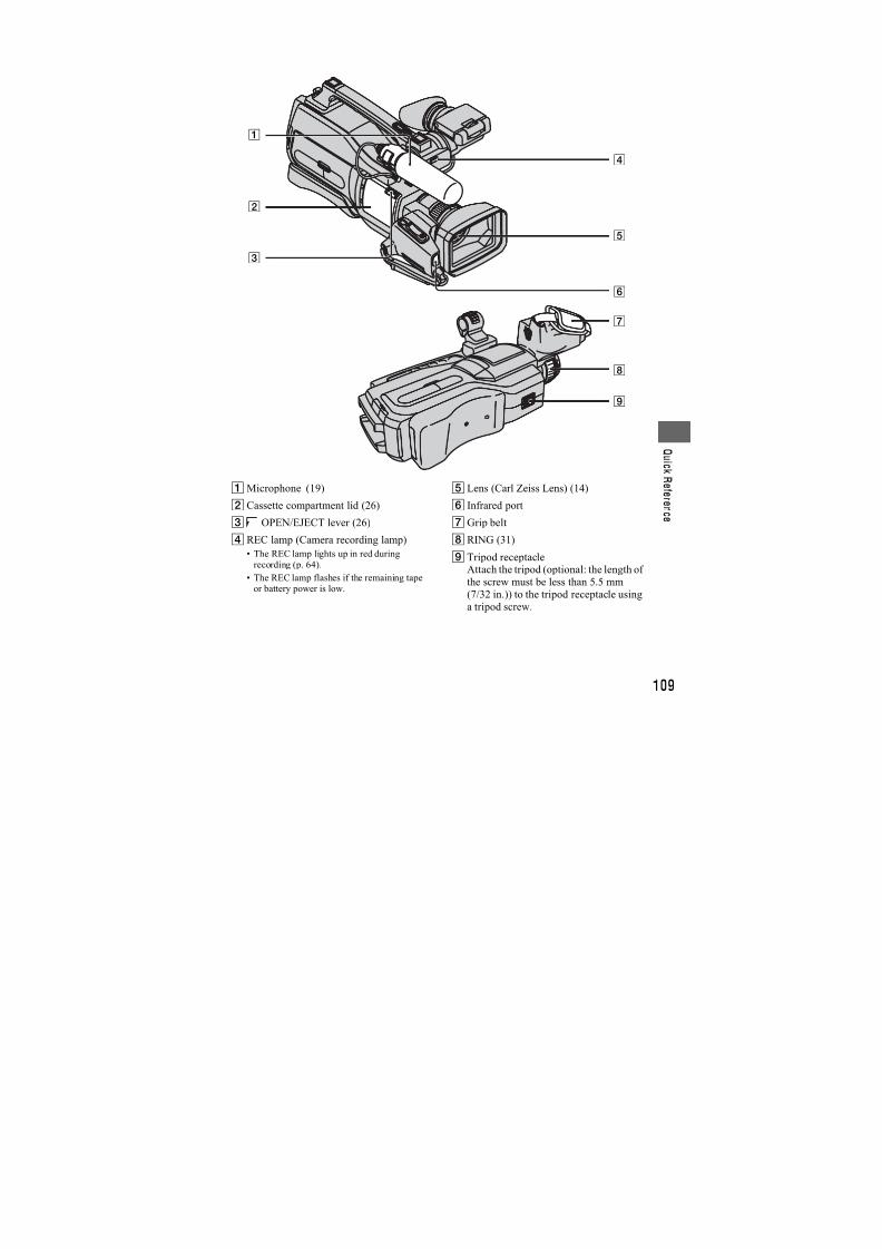
7/18/2019 SONY+HVR-HD1000 SERVICE MANUAL
http://slidepdf.com/reader/full/sonyhvr-hd1000-service-manual 390/42593
T r o u b l e s h o o t i n g
Memory Stick folders are full.
• You cannot create folders exceeding999MSDCF. You cannot delete created
folders using your camcorder.• You will have to format the “Memory
Stick Duo” (p. 53), or delete them usingyour computer.
x Dual Rec
Cannot save still picture.
• Do not eject “Memory Stick Duo”
while still images are being stored ontoit (p. 30).
x PictBridge compliant printer
Check the connected device.
• Switch off the printer and switch it onagain, then disconnect the USB cableand reconnect it.
Cannot print. Check the printer.
• Switch off the printer and switch it onagain, then disconnect the USB cableand reconnect it.
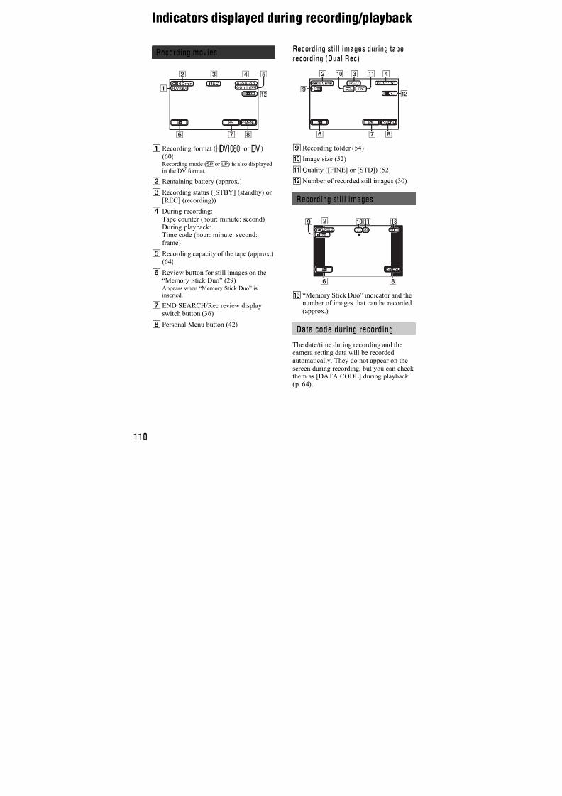
7/18/2019 SONY+HVR-HD1000 SERVICE MANUAL
http://slidepdf.com/reader/full/sonyhvr-hd1000-service-manual 391/42594
Additional Information
Using your camcorder abroad
Power supply
You can use your camcorder in anycountry/region using the AC Adaptorsupplied with your camcorder within theAC 100 V to 240 V, 50/60 Hz range.Use a commercially available AC plugadaptor [a], if necessary, depending on thedesign of the wall outlet [b].
On TV color systems
Your camcorder is PAL system, so its picture can only be viewed on a PALsystem TV with an AUDIO/VIDEO input
jack.
Viewing HDV format pictures recordedin HDV format
You need an HDV1080i compatible TV (or
monitor) with a component jack andAUDIO/VIDEO input jack. A componentvideo cable and A/V connecting cable arealso needed.
Viewing DV format pictures recordedin DV format
You need a TV (or monitor) with theAUDIO/VIDEO input jack. A connectingcable is also needed.
Simple setting of the clock by timedifference
You can easily set the clock to the localtime abroad by entering the time difference
between where you live and where you are.Select [WORLD TIME] in the (TIME/LANGU.) menu, then set the timedifference (p. 65).
System Used in
PAL Australia, Austria, Belgium,
China, Czech Republic,
Denmark, Finland, Germany,
Holland, Hong Kong, Hungary,
Italy, Kuwait, Malaysia,
New Zealand, Norway, Poland,
Portugal, Singapore,
Slovak Republic, Spain,
Sweden, Switzerland, Thailand,
United Kingdom, etc.
PAL - M Brazil
PAL - N Argentina, Paraguay, Uruguay.
SECAM Bulgaria, France, Guiana, Iran,
Iraq, Monaco, Russia, Ukraine,etc.
NTSC Bahama Islands, Bolivia,
Canada, Central America, Chile,
Colombia, Ecuador, Guyana,
Jamaica, Japan, Korea, Mexico,
Peru, Surinam, Taiwan,
the Philippines, the U.S.A.,
Venezuela, etc.
AC-L100 [a] [b]
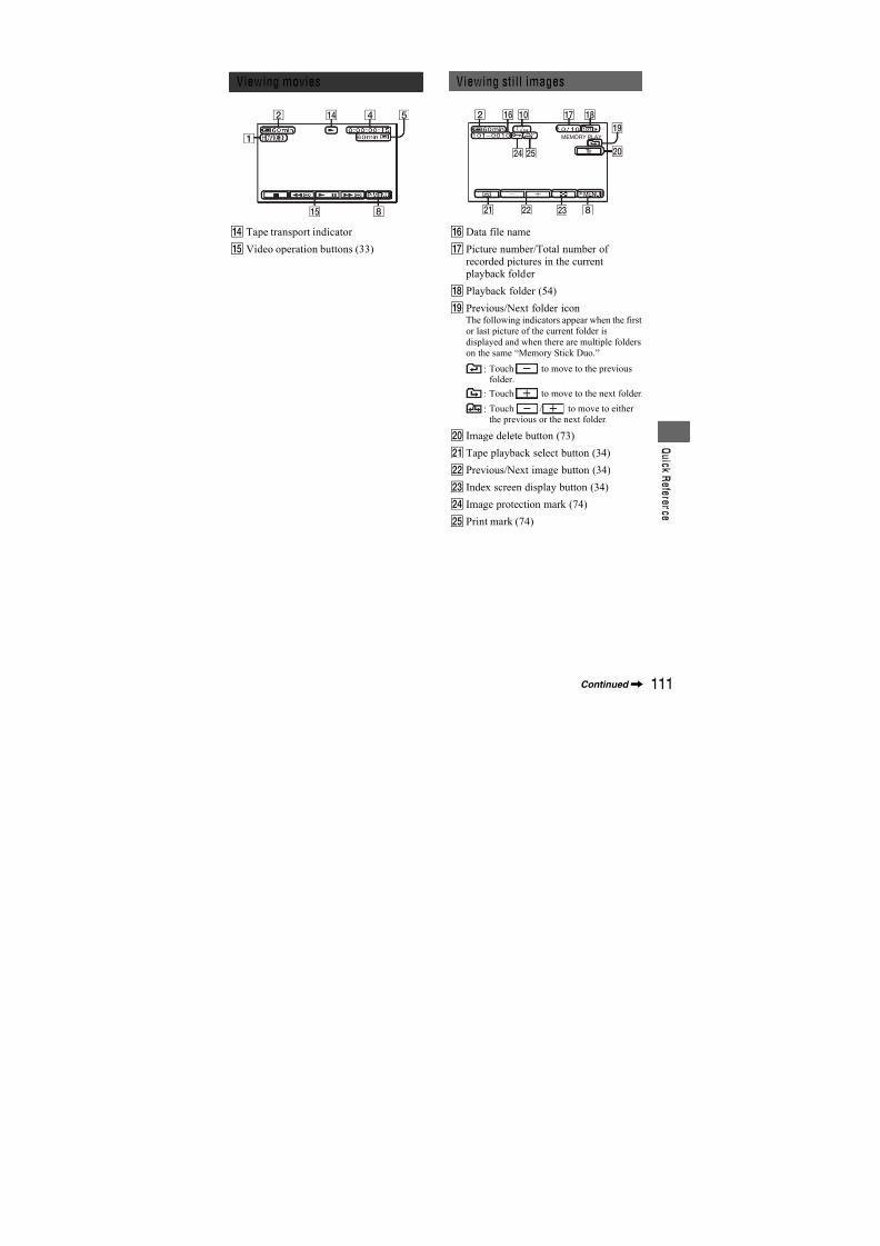
7/18/2019 SONY+HVR-HD1000 SERVICE MANUAL
http://slidepdf.com/reader/full/sonyhvr-hd1000-service-manual 392/42595
A d d i t i o n a l I n f o r m
a t i o n
Maintenance and precautions
Your camcorder is capable of recording in
both HDV and DV formats.You can use mini DV format cassettes only.Use a cassette with the mark.Your camcorder is not compatible with theCassette Memory function.
What is the HDV format?
The HDV format is a video formatdeveloped to record and play back digitalhigh definition (HD) video signals on a DV
cassette.Your camcorder adopts the Interlace modewith 1,080 effective scan lines of screenruling (1080i, number of pixels 1,440 ×1,080 dots).The video bit rate for recording is about 25Mbps.i.LINK is adopted for the digital interface,enabling a digital connection with an HDVcompatible TV or computer.
z Tips
• HDV signals are compressed in MPEG2 format,which is adopted in BS (broadcast satellite)
digital, terrestrial digital HDTV broadcastings,
in Blu-ray Disc recorders, etc.
Playback
Your camcorder can play back pictures in both the DV format and HDV1080i
specification.Your camcorder can play back picturesrecorded in the HDV 720/30p format, butcannot output it from the HDV/DVInterface (i.LINK).
To prevent a blank section from beingcreated on the tape
Go to the end of the recorded section usingEND SEARCH (p. 36) before you begin the
next recording when you have played backthe tape.
Copyright signal
x When you play backIf the cassette you play back on your
camcorder contains copyright signals, youcannot copy it to a tape in another videocamera connected to your camcorder.
x When you recordYou cannot record software on yourcamcorder that contains copyright controlsignals for copyright protection of software.[Cannot record due to copyright
protection.] appears on the LCD screen, or
on the viewfinder if you try to record suchsoftware. Your camcorder does not recordcopyright control signals on the tape whenit records.
Notes on use
x When not using your camcorder for along timeRemove the cassette and store it.
x To prevent accidental erasureSlide the write-protect tab on the cassette toset it to SAVE.
Usable cassette tapes
RECSAVE
REC: The cassette can berecorded.
SAVE: The cassette cannot berecorded (write-protected).
Continued,
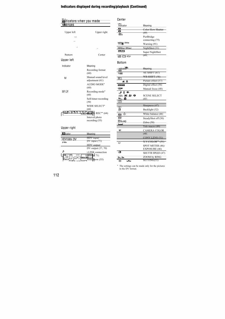
7/18/2019 SONY+HVR-HD1000 SERVICE MANUAL
http://slidepdf.com/reader/full/sonyhvr-hd1000-service-manual 393/42596
x When labeling the cassetteBe sure to place the label only on thelocations shown in the followingillustration so as not to cause a malfunction
of your camcorder.
x After using the cassetteRewind the tape to the beginning to avoiddistortion of the picture or the sound. Thecassette should then be put in its case, andstored in an upright position.
x When cleaning the gold-platedconnectorGenerally, clean the gold-plated connectoron a cassette with a cotton-wool swab afterevery 10 times it has been ejected.
If the gold-plated connector on the cassetteis dirty or dusty, the remaining tapeindicator may not show correctly.
A “Memory Stick” is a compact, portableIC recording medium with a large datacapacity.You can use the following types of“Memory Stick” listed below on thecamcorder. However, we do not guaranteethe operation of all types of “MemoryStick” on your camcorder. (See the list
below for more details.)
• This product cannot record or play data that uses“MagicGate” technology. “MagicGate” is a
copyright protection technology that records and
transfers the contents in an encrypted format.
• This product is compatible with “Memory Stick
Micro” (“M2”). “M2” is the abbreviation for the
“Memory Stick Micro.”
• Still image format: Your camcorder compresses
and records image data in the JPEG (Joint
Photographic Experts Group) format. The file
extension is “.JPG.”
• File names of still images:
– 101-0001: This file name appears on the
screen of your camcorder. – DSC00001.JPG: This file name appears on
the display of a computer.
• A “Memory Stick Duo” formatted by a
computer (Windows OS/Mac OS) does not have
guaranteed compatibility with your camcorder.
• Data read/write speed may vary depending on
the combination of the “Memory Stick Duo”
and “Memory Stick Duo” compliant product
you use.
• You can prevent accidental erasure of images
when you slide the write-protect tab on the“Memory Stick Duo” with a small taperedobject, to the write-protect position.
• Damaged or lost image data will not becompensated for, and may occur in the
following cases:
– If you eject the “Memory Stick Duo,” turn the
power off on your camcorder, or remove the
battery pack for replacement while your
camcorder is reading or writing image files on
the “Memory Stick Duo” (while the access
lamp is lit or flashing). – If you use the “Memory Stick Duo” near
magnets or magnetic fields.
• It is recommended to make a back-up of
important data on the hard disk of a computer.
About the “Memory Stick”
Do not put a labelalong this border.
Labeling position
Gold-plated connector
Types of “Memory Stick”Recording/ Playback
“Memory Stick Duo”
(with MagicGate) a“Memory Stick PRO Duo” a
“Memory Stick PRO-HG Duo” a*
* This camcorder does not support 8-bit parallel
data transfer, but supports 4-bit parallel data
transfer as is the case with “Memory Stick PRO
Duo”.
Maintenance and precautions (Continued)
7/18/2019 SONY+HVR-HD1000 SERVICE MANUAL
http://slidepdf.com/reader/full/sonyhvr-hd1000-service-manual 394/42597
A d d i t i o n a l I n f o r m
a t i o n
• Be careful not to apply excessive force when
writing on a memo area on a “Memory Stick
Duo.”
• Do not attach a label or the like on a “Memory
Stick Duo” or a Memory Stick Duo adaptor.• When you carry or store a “Memory Stick Duo,”
put it in its case.
• Do not touch, or allow metallic objects to come
into contact with the terminals.
• Do not bend, drop or apply strong force to the
“Memory Stick Duo.”
• Do not disassemble or modify the “Memory
Stick Duo.”
• Do not let the “Memory Stick Duo” get wet.
• Be careful to keep “Memory Stick Duo” mediaout of the reach of small children. There is
danger that a child might swallow it.
• Do not insert anything other than a “Memory
Stick Duo” into the Memory Stick Duo slot.
Doing so may cause a malfunction.
• Do not use or keep the “Memory Stick Duo” in
the following locations:
– Places subject to extremely high temperature,
such as a car parked outside in the summer.
– Places under direct sunlight.
– Places with extremely high humidity orsubject to corrosive gases.
x On the Memory Stick Duo adaptor• When using a “Memory Stick Duo” with a
“Memory Stick” compliant device, make sure to
insert the “Memory Stick Duo” into a Memory
Stick Duo adaptor.
• When inserting a “Memory Stick Duo” into a
Memory Stick Duo adaptor, make sure the
“Memory Stick Duo” is inserted facing in the
correct direction, then insert it all the way in. Note that improper use may cause a
malfunction. Also, if you force the “Memory
Stick Duo” into the Memory Stick Duo adaptorin the wrong direction, it may be damaged.
• Do not insert a Memory Stick Duo adaptor
without a “Memory Stick Duo” attached. Doingso may result in malfunctions of the unit.
x On a “Memory Stick PRO Duo”• The maximum memory capacity of a “Memory
Stick PRO Duo” that can be used on your
camcorder is 8 GB.
Notes on using “Memory Stick Micro”
• To use a “Memory Stick Micro” with the
camcorder, you need a Duo-sized M2 Adaptor.
Insert the “Memory Stick Micro” into the Duo-
sized M2 Adaptor, then insert the adaptor into
the Memory Stick Duo slot. If you insert a
“Memory Stick Micro” into the camcorder
without using a Duo-sized M2 Adaptor, you
might not be able to remove it from the
camcorder.
• Do not leave the “Memory Stick Micro” withinthe reach of small children. They mightaccidentally swallow it.
On image data compatibility
• Image data files recorded on a “Memory Stick
Duo” by your camcorder conform to the“Design rule for Camera File system” universal
standard established by the JEITA (Japan
Electronics and Information Technology
Industries Association).• On your camcorder, you cannot play back still
images recorded on other devices (DCR-
TRV900E or DSC-D700/D770) that do not
conform to the universal standard. (These
models are not sold in some regions.)
• If you cannot use a “Memory Stick Duo” thathas been used with another device, format it
with your camcorder (p. 64). Note that
formatting erases all information on the“Memory Stick Duo.”
• You may not be able to play back images withyour camcorder:
– When playing back image data modified on
your computer.
– When playing back image data recorded with
other devices.
Continued,
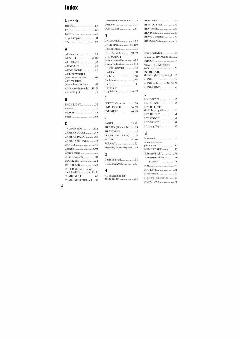
7/18/2019 SONY+HVR-HD1000 SERVICE MANUAL
http://slidepdf.com/reader/full/sonyhvr-hd1000-service-manual 395/42598
This unit is compatible with an“InfoLITHIUM” battery pack (L series).Your camcorder operates only with an“InfoLITHIUM” battery pack.“InfoLITHIUM” L series battery packshave the mark.
What is an “InfoLITHIUM” battery
pack?
An “InfoLITHIUM” battery pack is a
lithium-ion battery pack that has functionsfor communicating information related tooperating conditions between yourcamcorder and an optional AC Adaptor/charger.The “InfoLITHIUM” battery packcalculates the power consumptionaccording to the operating conditions ofyour camcorder, and displays the remaining
battery time in minutes.
With an AC Adaptor/charger, the remaining battery time and charging time appear.
To charge the battery pack
• Be sure to charge the battery pack before you
start using your camcorder.
• We recommend charging the battery pack in an
ambient temperature of between 10 °C to 30 °C
(50 °F to 86 °F) until the CHG (charge) lamp
turns off. If you charge the battery pack outside
of this temperature range, you may not be ableto charge it efficiently.
• After charging is complete, disconnect the cable
from the DC IN jack on your camcorder orremove the battery pack.
To use the battery pack effectively
• Battery pack performance decreases when the
surrounding temperature is 10 °C (50 °F) or below, and the length of time you can use the
battery pack becomes shorter. In that case, do
one of the following to use the battery pack for alonger time.
– Put the battery pack in a pocket to warm it up,and insert it in your camcorder right before
you start taking shots.
– Use a large capacity battery pack: NP-F770/
NP-F970 (optional).
• Frequent use of the LCD screen or a frequent
playback, fast forward or rewind operation
wears out the battery pack faster.We recommend using a large capacity battery pack: NP-F770/NP-F970 (optional).
• Be sure to set the POWER switch to OFF(CHG) when not recording or playing back on
your camcorder. The battery pack is also
consumed when your camcorder is in recordingstandby or playback pause.
• Have spare battery packs ready for two or three
times the expected recording time, and make
trial recordings before making the actual
recording.• Do not expose the battery pack to water. The
battery pack is not water resistant.
About the remaining battery timeindicator
• When the power goes off even though the
remaining battery time indicator indicates thatthe battery pack has enough power to operate,
charge the battery pack fully again. Remaining
battery time will be indicated correctly. Note,however, that the battery indication will not be
restored if it is used in high temperatures for a
long time, or if left in a fully charged state, or
when the battery pack is frequently used. Use
the remaining battery time indication as a rough
guide only.
• TheE mark that indicates low battery flashes
even if there are still 5 to 10 minutes of batterytime remaining, depending on the operating
conditions or ambient temperature.
About storage of the battery pack
• If the battery pack is not used for a long time,fully charge the battery pack and use it up on
your camcorder once a year to maintain proper
function. To store the battery pack, remove it
from your camcorder and put it in a dry, cool place.
About battery life
• Battery capacity decreases over time and
through repeated use. If decreased usage time between charges becomes significant, it is
probably time to replace it with a new one.
About the “InfoLITHIUM”battery pack
Maintenance and precautions (Continued)
7/18/2019 SONY+HVR-HD1000 SERVICE MANUAL
http://slidepdf.com/reader/full/sonyhvr-hd1000-service-manual 396/42599
A d d i t i o n a l I n f o r m
a t i o n
• Each battery’s life is governed by storage,
operating and environmental conditions.
The HDV/DV Interface on this unit is ani.LINK-compliant Interface. This sectiondescribes the i.LINK standard and itsfeatures.
What is i.LINK?
i.LINK is a digital serial interface fortransferring digital video, digital audio, andother data to other i.LINK-compatibledevices. You can also control other devicesusing the i.LINK.i.LINK-compatible devices can beconnected using an i.LINK cable. Possibleapplications are operations and data
transactions with various digital AVdevices.When two or more i.LINK-compatibledevices are daisy-chained with the unit,operation becomes possible from anydevice in the chain. Note that operationmethod may vary, or data transactions maynot be possible, depending on specificationsand characteristics of the connecteddevices.
b Notes
• Normally, only one device can be connected to
this unit with an i.LINK cable. When
connecting this unit to an HDV/DV compatible
device having two or more HDV/DVInterfaces, refer to the operating instructions of
the device to be connected.
z Tips
• i.LINK is a more familiar term for the
IEEE1394 data transport bus proposed by Sony,
and is a trademark approved by manycorporations.
• IEEE1394 is an international standardstandardized by the Institute of Electrical and
Electronics Engineers.
About the i.LINK Baud rate
i.LINK’s maximum baud rate variesaccording to the device. There are 3 types.
S100 (approx. 100 Mbps*)S200 (approx. 200 Mbps)S400 (approx. 400 Mbps)
The baud rate is listed under“Specifications” in the operatinginstructions of each piece of equipment. Itis also indicated near the i.LINK interfaceon some devices.The baud rate may differ from the indicated
value when the unit is connected to a devicewith a different maximum baud rate.
Mbps stands for “megabits per second,” orthe amount of data that can be sent orreceived in one second. For example, a
baud rate of 100 Mbps means that 100megabits of data can be sent in one second.
To use i.LINK functions on this unitFor details on how to dub when this unit isconnected to other video devices having ani.LINK Interface, see page 68.This unit can also be connected to otheri.LINK-compatible devices made by Sony(e.g. a VAIO series personal computer) aswell as to video devices.Some i.LINK compatible video devices,such as Digital Televisions, DVD,
MICROMV or HDV recorders/players arenot compatible with this unit. Beforeconnecting to other devices, be sure toconfirm whether the device is compatiblewith an HDV/DV device or not. For detailson precautions and compatible applicationsoftware, refer also to the operatinginstructions for the device to be connected.
About i.LINK
* What is Mbps?
Continued,

7/18/2019 SONY+HVR-HD1000 SERVICE MANUAL
http://slidepdf.com/reader/full/sonyhvr-hd1000-service-manual 397/425100
b Notes
• When connecting your camcorder to anotheri.LINK-compatible device, be sure to turn off
the power of the device and disconnect the AC
Adaptor from the wall outlet (wall socket) before connecting or disconnecting the i.LINK
cable.
About the required i.LINK cable
Use the Sony i.LINK 4-pin-to-4-pin cable(during HDV/DV dubbing).
• x.v.Color is a more familiar term for the xvYCCstandard proposed by Sony, and is a trademark
of Sony.
• xvYCC is an international standard for color
space in video. This standard can express awider color range than the currently used
broadcast standard.
On use and care• Do not use or store the camcorder and
accessories in the following locations.
– Anywhere extremely hot or cold. Never leave
them exposed to temperatures above 60 °C
(140 °F), such as under direct sunlight, near
heaters or in a car parked in the sun. They
may malfunction or become deformed.
– Near strong magnetic fields or mechanical
vibration. The camcorder may malfunction.
– Near strong radio waves or radiation. The
camcorder may not be able to record properly.
– Near AM receivers and video equipment.
Noise may occur.
– On a sandy beach or anywhere dusty. If sand
or dust gets in your camcorder, it maymalfunction. Sometimes this malfunction
cannot be repaired.
– Near windows or outdoors, where the LCD
screen, the viewfinder, or the lens may be
exposed to direct sunlight. This damages the
inside of the viewfinder or the LCD screen. – Anywhere very humid.
• Operate your camcorder on DC 6.8 V (battery
pack) or DC 8.4 V (AC Adaptor).
• For DC or AC operation, use the accessories
recommended in these operating instructions.
• Do not let your camcorder get wet, for example,
from rain or sea water. If your camcorder gets
wet, it may malfunction. Sometimes thismalfunction cannot be repaired.
• If any solid object or liquid gets inside the
casing, unplug your camcorder and have itchecked by a Sony dealer before operating it
any further.
• Avoid rough handling, disassembling,
modifying, physical shock, or impact such as
hammering, dropping or stepping on the product. Be particularly careful of the lens.
• Keep the POWER switch setting to OFF (CHG)
when you are not using your camcorder.• Do not wrap your camcorder with a towel, for
example, and operate it. Doing so might cause
heat to build up inside.
• When disconnecting the power cord (mains
lead), pull it by the plug and not the cord (lead).
• Do not damage the power cord (mains lead)
such as by placing anything heavy on it.
• Keep metal contacts clean.
• If the battery electrolytic liquid has leaked,
– consult your local authorized Sony servicefacility.
– wash off any liquid that may have contacted
your skin.
– if any liquid gets in your eyes, wash with
plenty of water and consult a doctor.
x When not using your camcorder for along time• Periodically turn on the camcorder and play a
cassette for about 3 minutes.
• Use up the battery pack completely beforestoring it.
About x.v.Color
On using your camcorder
Maintenance and precautions (Continued)
7/18/2019 SONY+HVR-HD1000 SERVICE MANUAL
http://slidepdf.com/reader/full/sonyhvr-hd1000-service-manual 398/425101
A d d i t i o n a l I n f o r m
a t i o n
Moisture condensation
If your camcorder is brought directly from acold place to a warm place, moisture maycondense inside your camcorder, on thesurface of the tape, or on the lens. In thisstate, the tape may stick to the head drumand be damaged or your camcorder may notoperate correctly. If there is moisture insideyour camcorder, [%Z Moisturecondensation. Eject the cassette] or [% Moisture condensation. Turn off for 1H.]appears. The indicator will not appear whenthe moisture condenses on the lens.
x If moisture condensation has occurred None of the functions except cassetteejection will work. Eject the cassette, turnoff your camcorder, and leave it for aboutone hour with the cassette lid open. Yourcamcorder can be used again when both ofthe following conditions are met:
• The warning message does not appear when the
power is turned on.
• Neither% orZ flash when a cassette is inserted
and video operation buttons are touched.If moisture starts to condense, yourcamcorder sometimes cannot detectcondensation. If this happens, the cassette issometimes not ejected for 10 seconds afterthe cassette lid is opened. This is not amalfunction. Do not close the cassette liduntil the cassette is ejected.
x Note on moisture condensationMoisture may condense when you bringyour camcorder from a cold place into awarm place (or vice versa) or when you useyour camcorder in a humid place as shown
below.
• When you bring your camcorder from a ski
slope into a place warmed up by a heatingdevice.
• When you bring your camcorder from an airconditioned car or room into a hot place outside.
• When you use your camcorder after a squall or a
shower.
• When you use your camcorder in a hot and
humid place.
x How to avoid moisture condensationWhen you bring your camcorder from acold place into a warm place, put yourcamcorder in a plastic bag and seal it
tightly. Remove the bag when the airtemperature inside the plastic bag hasreached the surrounding temperature (afterabout one hour).
Video head
If you play back a tape recorded in HDVformat, the image and sound may freeze fora while (about 0.5 seconds).This occurs if the HDV signals cannot berecorded or played back correctly becauseof dirt on the tape or video head. Dependingon the cassette, this fairly infrequentlyoccurs even if the cassette is brand new oris not used a lot.If this freezing point is created while
playing back, you can solve this problemand see the pictures by rewinding afterslightly forwarding. Such a freezing pointcannot be recovered if it was created while
recording.To prevent such a problem, use the Sonymini DV cassette.
• If the following problem occurs, clean the video
heads for 10 seconds with the cleaning cassette.
– Playback pictures do not move.
– Playback pictures do not appear.
– The sound breaks off.
– [x Dirty video head. Use a cleaning
cassette.] appears on the screen during
recording.
– The following phenomenon occurs in HDV
format.
The playbackscreen pauses.
The playback screengoes blank.(Solid blue screen)
Continued,
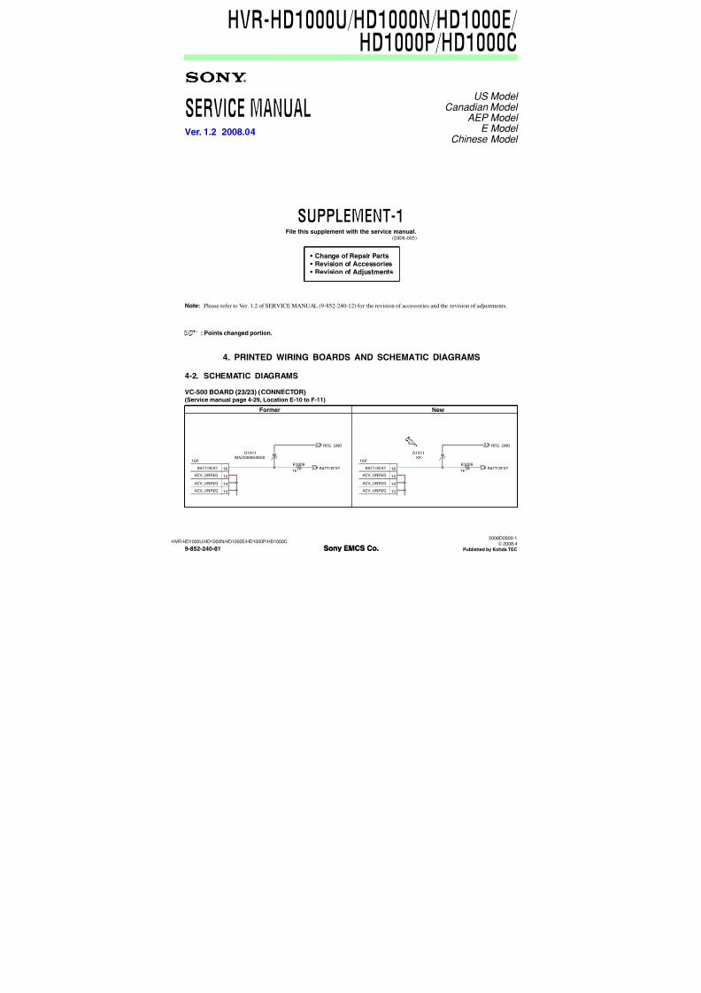
7/18/2019 SONY+HVR-HD1000 SERVICE MANUAL
http://slidepdf.com/reader/full/sonyhvr-hd1000-service-manual 399/425102
– The following phenomenon occurs in DV
format.
• The video heads will degrade after long use. If
you cannot obtain a clear image even after usinga cleaning cassette (optional), it might be
because the video heads are worn out. Please
contact your Sony dealer or local authorized
Sony service facility to have the video heads
replaced.
LCD screen
• Do not exert excessive pressure on the LCD
screen, as it may cause damage.
• If your camcorder is used in a cold place, aresidual image may appear on the LCD screen.
This is not a malfunction.
• While using your camcorder, the back of the
LCD screen may heat up. This is not amalfunction.
x To clean the LCD screenIf fingerprints or dust make the LCD screendirty, it is recommended you use a softcloth to clean it. When you use the LCD
Cleaning Kit (optional), do not apply thecleaning liquid directly to the LCD screen.Use cleaning paper moistened with theliquid.
x On adjustment of the touch panel(CALIBRATION)The buttons on the touch panel may notwork correctly. If this happens, follow the
procedure below. It is recommended youconnect your camcorder to the wall outlet(wall socket) using the supplied ACAdaptor during the operation.
1 Slide the POWER switch repeatedly toPLAY/EDIT.
2 Touch t [MENU]t (STANDARD SET)t [CALIBRATION]t .
3 Touch the “×” displayed on the screen withthe corner of the “Memory Stick Duo” orthe like.
The position of the “×” changes.
To cancel, touch [CANCEL].
If you did not press the right spot, start fromstep 3 again.
b Notes
• You cannot calibrate the LCD screen if it isrotated.
On handling the casing• If the casing is soiled, clean the camcorder body
with a soft cloth lightly moistened with water,and then wipe the casing with a dry soft cloth.
• Avoid the following to avoid damage to the
finish.
– Using chemicals such as thinner, benzine,
alcohol, chemical cloths, repellent, insecticide
and sunscreen.
– Handling with above substances on yourhands.
– Leaving the casing in contact with rubber orvinyl objects for a long period of time.
About care and storage of the lens
• Wipe the surface of the lens clean with a soft
cloth in the following instances:
– When there are fingerprints on the lens
surface.
– In hot or humid locations
– When the lens is exposed to salty air such as
at the seaside.
• Store in a well-ventilated location subject to
little dirt or dust.
Block-noise appears.
The playback screen goes blank.(Solid blue screen)
CALIBRATION
Touch the "x"
1/3
CANCEL
Maintenance and precautions (Continued)
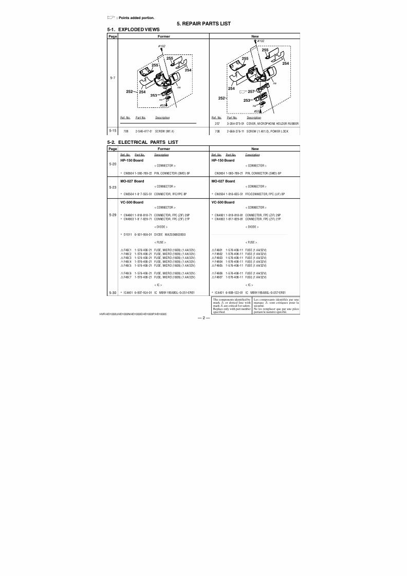
7/18/2019 SONY+HVR-HD1000 SERVICE MANUAL
http://slidepdf.com/reader/full/sonyhvr-hd1000-service-manual 400/425103
A d d i t i o n a l I n f o r m
a t i o n
• To prevent mold, periodically clean the lens as
described above. It is recommended that you
operate your camcorder about once a month to
keep it in optimum state for a long time.
On charging the pre-installedrechargeable battery
Your camcorder has a pre-installedrechargeable battery to retain the date, time,and other settings even when the POWERswitch is set to OFF (CHG). The pre-installed rechargeable battery is alwayscharged while your camcorder is connectedto the wall outlet (wall socket) via the AC
Adaptor or while the battery pack isinserted. The rechargeable battery will befully discharged in about 3 months if youdo not use your camcorder at all without theAC Adaptor connected or the battery packattached. Use your camcorder aftercharging the pre-installed rechargeable
battery.However, even if the pre-installedrechargeable battery is not charged, the
camcorder operation will not be affected aslong as you are not recording the date.
x ProceduresConnect your camcorder to a wall outlet(wall socket) using the supplied ACAdaptor, and leave it with the POWERswitch set to OFF (CHG) for more than 24hours.
Removing dust from inside the viewfinder
1 Remove the viewfinder.
While sliding the viewfinder releaselever downward1, turn the viewfindercounterclockwise until the | markingson the left side are aligned2, thenremove the viewfinder upward 3.
2 Remove dust from inside the
viewfinder and the part shownbelow with a blower.
3 Follow the reverse procedure of step
1. Align the | markings on the left
side and attach the viewfinder by
pressing it downward lightly. Thenturn it clockwise until it is clicked.
3
2
1
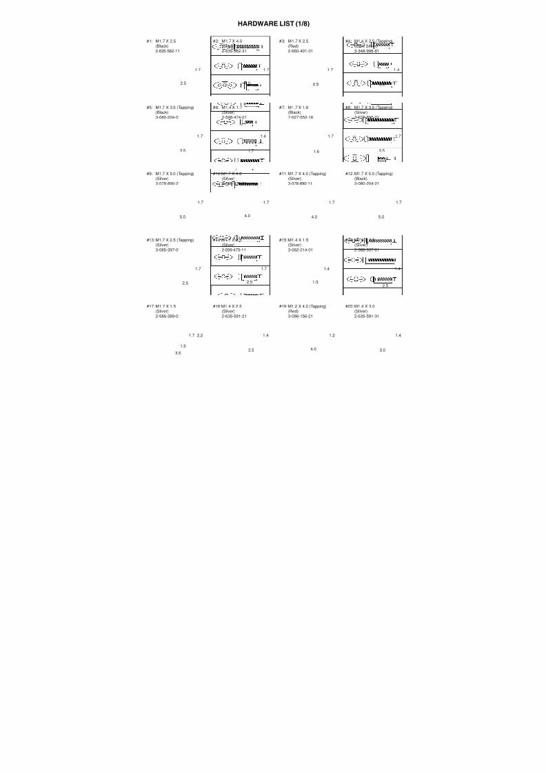
7/18/2019 SONY+HVR-HD1000 SERVICE MANUAL
http://slidepdf.com/reader/full/sonyhvr-hd1000-service-manual 401/425104
Specifications
System
Video recording system (HDV)
2 rotary heads, Helical scanning system
Video recording system (DV)2 rotary heads, Helical scanning system
Still image recording system
Exif Ver. 2.2*1
Audio recording system (HDV)
Rotary heads, MPEG-1 Audio Layer -2,
Quantization: 16 bits (Fs 48 kHz,
stereo)
transfer rate: 384 kbps
Audio recording system (DV)Rotary heads, PCM system
Quantization: 12 bits (Fs 32 kHz, stereo
1, stereo 2), 16 bits (Fs 48 kHz, stereo)
Video signal
PAL color, CCIR standards
1080/50i specification
Usable cassette
Mini DV cassette with the mark
printedTape speed (HDV)
Approx. 18.81 mm/s
Tape speed (DV)
SP: Approx. 18.81 mm/s
LP: Approx. 12.56 mm/s
Recording/playback time (HDV)
60 min (using a DVM60 cassette)
Recording/playback time (DV)
SP: 60 min (using a DVM60 cassette)LP: 90 min (using a DVM60 cassette)
Fast forward/rewind time
Approx. 2 min 40 s (using a DVM60
cassette and rechargeable battery pack)
Approx. 1 min 45 s (using a DVM60
cassette and AC Adaptor)
Viewfinder
Electric viewfinder (color)
Image device
6.3 mm (1/2.9 type) CMOS sensor
Recording pixels (still, 4:3):
Max. 6.1 mega (2 848 × 2 136) pixels*2
Gross: Approx. 3 200 000 pixels
Effective (movie, 16:9):
Approx. 2 280 000 pixels
Effective (movie, 4:3):
Approx. 1 710 000 pixels
Effective (still, 16:9):
Approx. 2 280 000 pixels
Effective (still, 4:3):
Approx. 3 040 000 pixels
Lens
Carl Zeiss Vario-Sonnar T
10 × (Optical), 20 × (Digital)
Focal length
f=5.4 ~ 54 mm (7/32 ~ 2 1/4 in.)
When converted to a 35 mm still
camera
In TAPE: 40 ~ 400 mm (1 5/8 ~ 15 3/4
in.) (16:9), 49 ~ 490 mm (1 15/16 ~
19 3/8 in.) (4:3)
In MEMORY: 40 ~ 400 mm (1 5/8 ~
15 3/4 in.) (16:9), 37 ~ 370 mm (1 1/2 ~
14 5/8 in.) (4:3)
F1.8 ~ 2.9
Filter diameter: 37 mm (1 1/2 in.)
Color temperature
[AUTO], [ONE PUSH], [INDOOR]
(3 200 K),
[OUTDOOR] (5 800 K)
Minimum illumination
5 lx (lux) ([AUTOSLW SHTR] [ON],
Shutter speed 1/25 sec)
0 lx (lux) (during NightShot function)
*1“Exif” is a file format for still images,
established by the JEITA (Japan
Electronics and Information Technology
Industries Association). Files in this
format can have additional information
such as your camcorder’s setting
information at the time of recording.
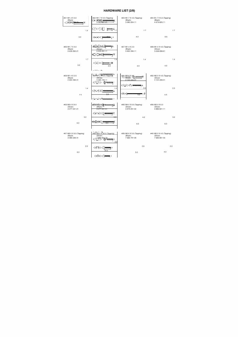
7/18/2019 SONY+HVR-HD1000 SERVICE MANUAL
http://slidepdf.com/reader/full/sonyhvr-hd1000-service-manual 402/425105
A d d i t i o n a l I n f o r m
a t i o n
*2The unique pixel array of Sony’s
ClearVid CMOS sensor and image
processing system (new Enhanced
Imaging Processor) allows for still
image resolution equivalent to the sizes
described.
Input/Output connectors
VIDEO OUT jack
Pin jack
1 Vp-p, 75 Ω (ohms)
S VIDEO OUT jack
4pin mini DIN
Luminance signal: 1 Vp-p, 75 Ω (ohms)Chrominance signal: 0.3 Vp-p, 75 Ω
(ohms)
AUDIO OUT jack
Pin jack
Audio signal: 327 mV (at load
impedance 47 k Ω (kilohms)), Output
impedance with less than 2.2 k Ω
(kilohms)
COMPONENT OUT jackY: 1 Vp-p, 75 Ω (ohms)
PB/PR , CB/CR : ± 350 mV, 75 Ω (ohms)
HDMI OUT jack
Type A (19-pin)
Headphone jack
Stereo minijack (Ø 3.5 mm)
LANC jack
Stereo mini-minijack (Ø 2.5 mm)
USB jackB
MIC (PLUG IN POWER) jack
Stereo minijack (Ø 3.5 mm)
HDV/DV jack
i.LINK Interface (IEEE1394, 4-pin
connector S100)
LCD screen
Picture6.7 cm (2.7 type, aspect ratio 16:9)
Total dot number
211 200 (960 × 220)
General
Power requirements
DC 7.2 V (battery pack)
DC 8.4 V (AC Adaptor)Average power consumption
During camera recording using the
viewfinder with normal brightness:
HDV recording 4.4 W
DV recording 4.2 W
During camera recording using the
LCD & viewfinder with normal
brightness:
HDV recording 4.8 WDV recording 4.6 W
Operating temperature
0 °C to + 40 °C (32 °F to 104 °F)
Storage temperature
-20 °C to + 60 °C (-4 °F to + 140 °F)
Dimensions (approx.)
265 × 231 × 460 mm
(10 4/8 × 9 1/8 × 18 1/8 in.) (w/h/d)
including the projecting parts265 × 231 × 460 mm
(10 4/8 × 9 1/8 × 18 1/8 in.) (w/h/d)
including the projecting parts with the
supplied battery pack NP-F570
attached
Mass (approx.)
2.7 kg (6 lb 0 oz) main unit only
3.0 kg (6 lb 10 oz) including the NP-
F570 rechargeable battery pack and
cassette (PHDVM-63DM), and lens
hood with lens cover , microphone.
Supplied accessories
See page 18.
AC Adaptor AC-L100
Power requirements
AC 100 V - 240 V, 50/60 Hz
Current consumption
0.35 - 0.18 A
Power consumption
18 W
Continued,
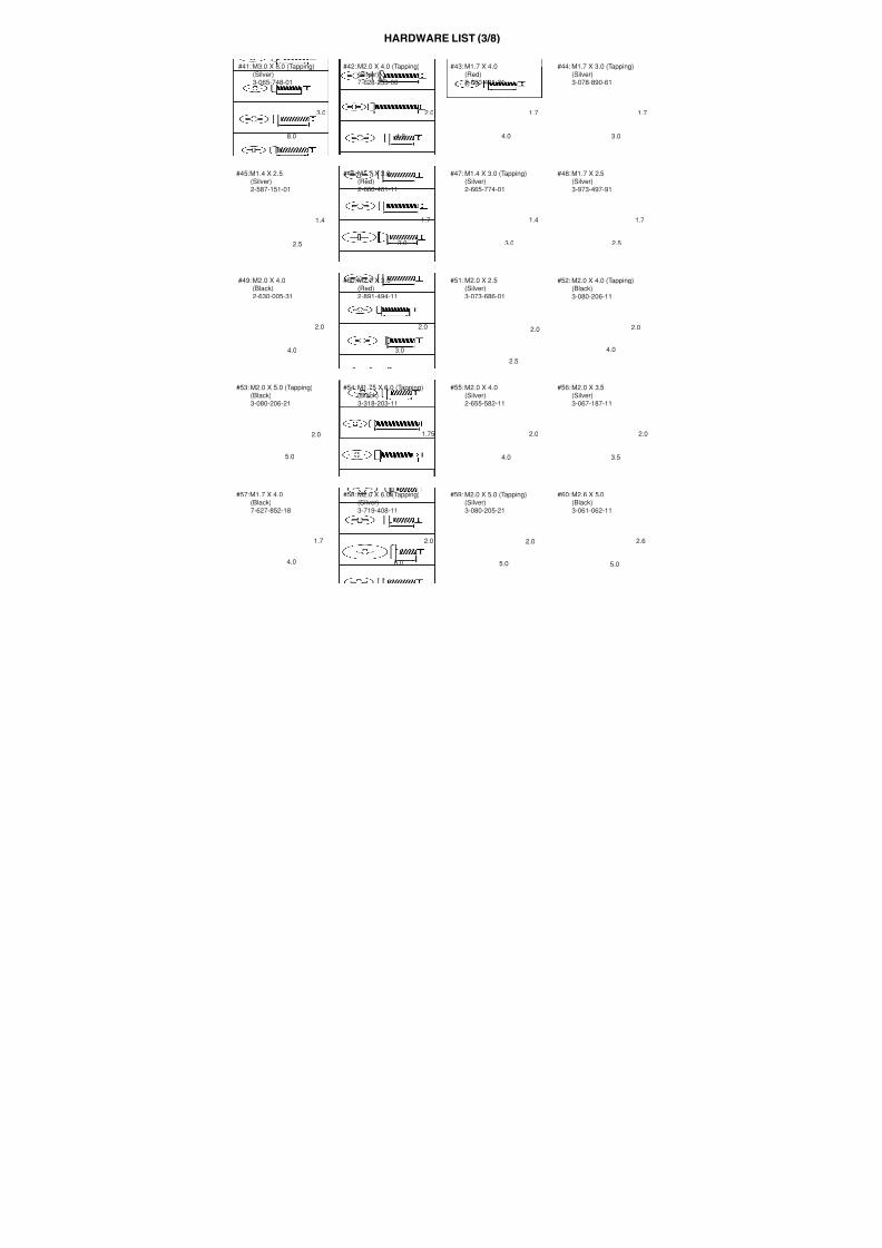
7/18/2019 SONY+HVR-HD1000 SERVICE MANUAL
http://slidepdf.com/reader/full/sonyhvr-hd1000-service-manual 403/425106
Output voltage
DC 8.4 V*
Operating temperature
0 °C to + 40 °C (32 °F to 104 °F)
Storage temperature
-20 °C to + 60 °C (-4 °F to + 140 °F)
Dimensions (approx.)
48 × 29 × 81 mm (1 15/16 × 1 3/16 ×
3 1/4 in.) (w/h/d) excluding the
projecting parts
Mass (approx.)
170 g (6.0 oz) excluding the power cord
(mains lead)
* See the label on the AC Adaptor for other
specifications.
Rechargeable battery pack (NP-F570)
Maximum output voltage
DC 8.4 V
Output voltage
DC 7.2 V
Capacity
15.8 Wh (2 200 mAh)
Dimensions (approx.)
38.4 × 20.6 × 70.8 mm
(1 9/16 × 13/16 × 2 7/8 in.)
Mass (approx.)
100 g (3.5 oz)
Operating temperature
0 °C to + 40 °C (32 °F to 104 °F)
Type
Lithium ion
Design and specifications are subject to change
without notice.
On trademarks
• HDV and the HDV logo are trademarks of Sony
Corporation and Victor Company of Japan, Ltd.
• “Memory Stick,” “ ,” “Memory Stick
Duo,” “ ,” “Memory Stick
PRO Duo,” “ ,”“Memory Stick PRO-HG Duo,”
“ ,” “Memory Stick
Micro,” “MagicGate,” “ ,”“MagicGate Memory Stick” and “MagicGate
Memory Stick Duo” are trademarks of Sony
Corporation.
• “InfoLITHIUM” is a trademark of Sony
Corporation.
• i.LINK and are trademarks of SonyCorporation.
• is a trademark.
• “x.v.Color” is a trademark of Sony Corporation.
• Microsoft, Windows, and Windows Media,Windows Vista are trademarks or registered
trademarks of U.S. Microsoft Corporation in the
U.S. and other countries.
• Macintosh and Mac OS are trademarks of Apple
Inc. in the U.S. and other countries.
• HDMI, the HDMI logo, and High-DefinitionMultimedia Interface are trademarks orregistered trademarks of HDMI Licensing LLC.
• Intel, Intel Core and Pentium are eitherregistered trademarks or trademarks of Intel
Corporation and its subsidiaries in the United
States and/or other countries.
• Adobe and Adobe Reader are either registered
trademarks or trademarks of Adobe Systems
Incorporated in the United States and/or other
countries.
All other product names mentioned herein may be
the trademarks or registered trademarks of their
respective companies. Furthermore, ™ and “®”
are not mentioned in each case in this manual.
Notes on the License
ANY USE OF THIS PRODUCT OTHER THAN
CONSUMER PERSONAL USE IN ANY
MANNER THAT COMPLIES WITH THE
MPEG-2 STANDARD FOR ENCODING
VIDEO INFORMATION FOR PACKAGEDMEDIA IS EXPRESSLY PROHIBITED
WITHOUT A LICENSE UNDER APPLICABLE
PATENTS IN THE MPEG-2 PATENTPORTFOLIO, WHICH LICENSE IS
AVAILABLE FROM MPEG LA, L.L.C., 250
STEELE STREET, SUITE 300, DENVER,COLORADO 80206.
Specifications (Continued)
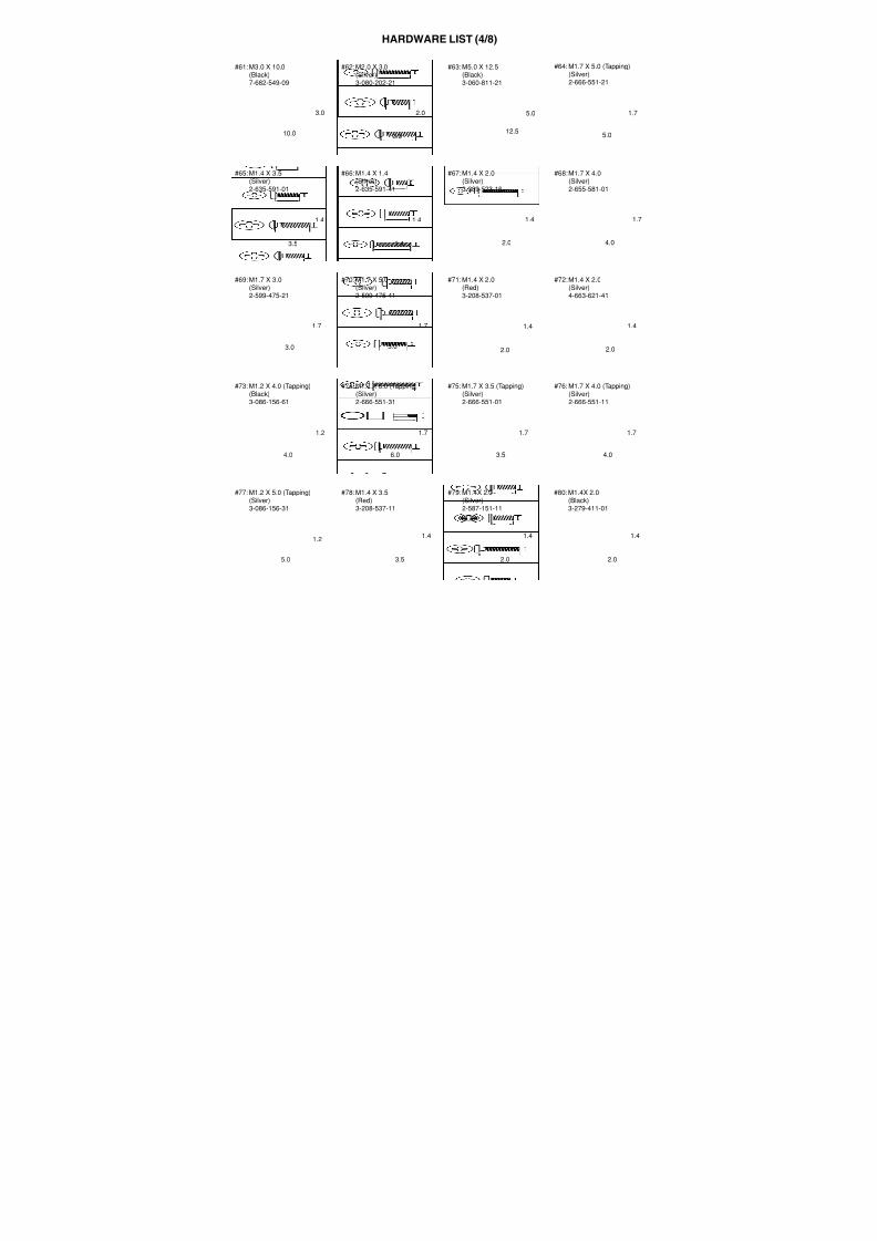
7/18/2019 SONY+HVR-HD1000 SERVICE MANUAL
http://slidepdf.com/reader/full/sonyhvr-hd1000-service-manual 404/425107
Q u i c k R e f
e r e n c e
Quick Reference
Identifying parts and controls
The numbers in ( ) are reference pages.
A Cold shoe
B HDV/DV Interface (i.LINK) (37, 69,71)
C LANC jack (blue)The LANC control jack is used forcontrolling the tape transport of videodevices and peripherals connected to it.
Di (Headphone) jack
E REC START/STOP button (28)
F Power zoom lever (30)
G PHOTO button (29)
H POWER switch (24)
I (USB) jack (75)
J Access lamp (26, 96)
K “Memory Stick Duo” slot (26)
L HDMI OUT jack (Output only) (37)
• The available video signals are read, and the
appropriate output format is selected and
output automatically.
• You can check the setup value of HDMI
OUTPUT on [STATUS CHECK] (p. 63).
M RESET button
Initializes all the settings, including thesetting of the date and time (Menu itemscustomized on Personal Menu are notinitialized).
N A/V (audio/video) OUT jack (37, 69)
O S VIDEO OUT jack (37)
P COMPONENT OUT jack (37)
B
C
D
A
E
F
G
H
I
J
K
L
M N O P
Continued,
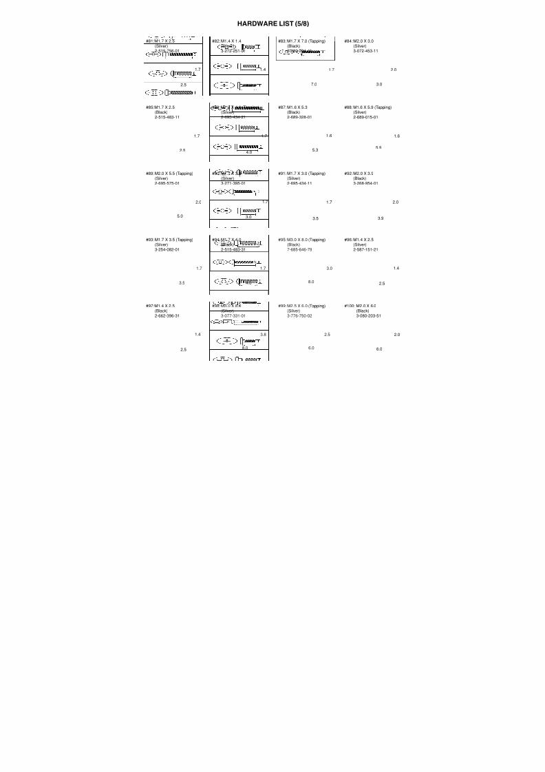
7/18/2019 SONY+HVR-HD1000 SERVICE MANUAL
http://slidepdf.com/reader/full/sonyhvr-hd1000-service-manual 405/425108
A Eyecup
B Viewfinder (25)
C LCD screen/touch panel (13, 25)
D LCD ON/OFF switch (25)
E Lens hood release lever (20)
F Viewfinder lens adjustment lever (25)
G Hook for the Shoulder beltAttach the Shoulder belt (optional).
H BATT (battery) RELEASE button (22)
I Battery pack (21)
J CHG (charge) lamp (21)
K DC IN jack (21)
L MANUAL button (31)
M NIGHTSHOT switch (31)
N BACK LIGHT button (32)
O DISPLAY/BATT INFO button (25)
P MEMORY mode lamp (24)
Q TAPE mode lamp (24)
R PLAY/EDIT mode lamp (24)
F
E
D
C
B
A
G
H
J
I
K
L M N O P Q R
Identifying parts and controls (Continued)
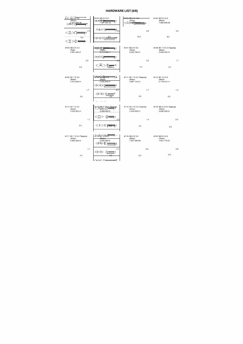
7/18/2019 SONY+HVR-HD1000 SERVICE MANUAL
http://slidepdf.com/reader/full/sonyhvr-hd1000-service-manual 406/425109
Q u i c k R e f
e r e n c e
A Microphone (19)
B Cassette compartment lid (26)
C OPEN/EJECT lever (26)
D REC lamp (Camera recording lamp)
• The REC lamp lights up in red during
recording (p. 64).
• The REC lamp flashes if the remaining tapeor battery power is low.
E Lens (Carl Zeiss Lens) (14)
F Infrared port
G Grip belt
H RING (31)
I Tripod receptacleAttach the tripod (optional: the length ofthe screw must be less than 5.5 mm(7/32 in.)) to the tripod receptacle usinga tripod screw.
A
B
C
D
E
F
G
H
I
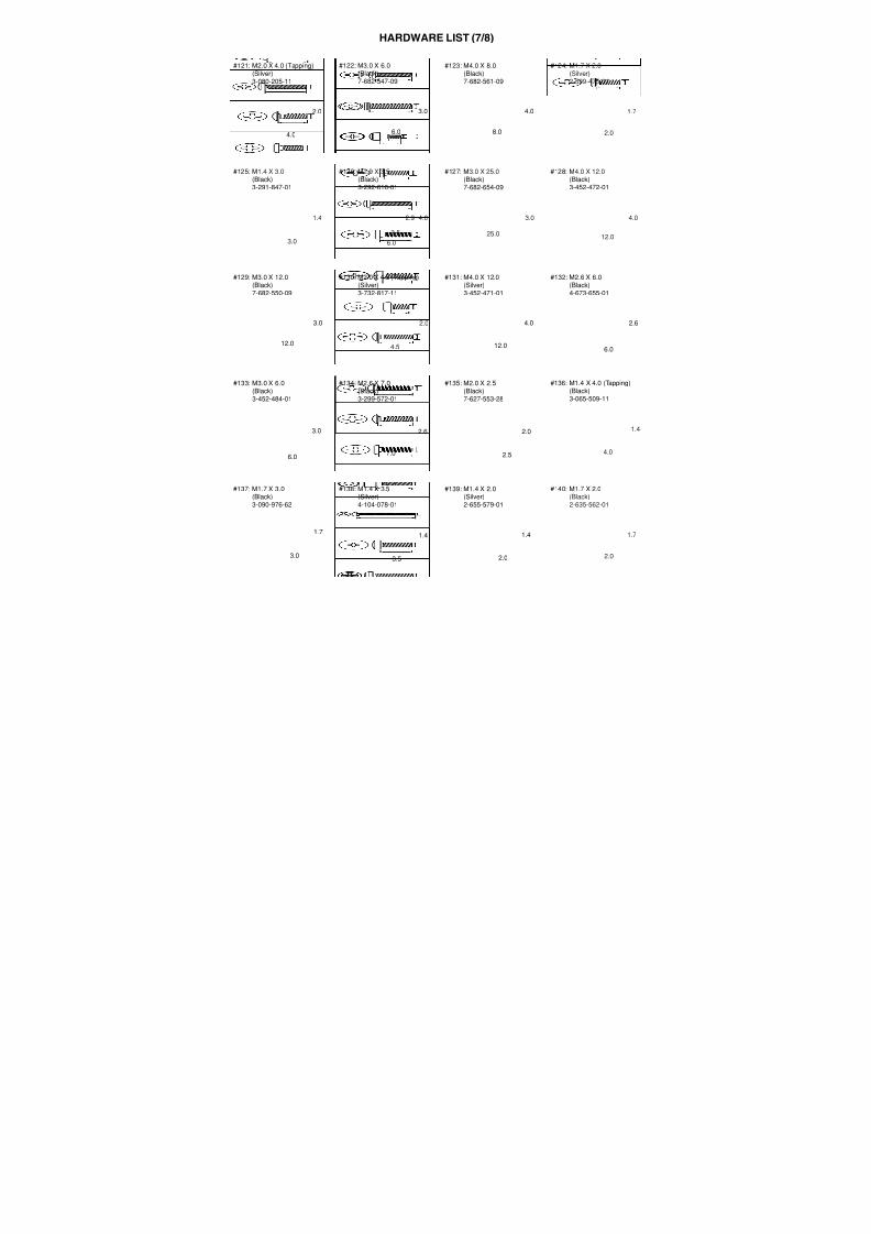
7/18/2019 SONY+HVR-HD1000 SERVICE MANUAL
http://slidepdf.com/reader/full/sonyhvr-hd1000-service-manual 407/425110
Indicators displayed during recording/playback
A Recording format ( or )
(60)Recording mode ( SP or LP ) is also displayedin the DV format.
B Remaining battery (approx.)
C Recording status ([STBY] (standby) or[REC] (recording))
D During recording:Tape counter (hour: minute: second)During playback:
Time code (hour: minute: second:frame)
E Recording capacity of the tape (approx.)(64)
F Review button for still images on the“Memory Stick Duo” (29)Appears when “Memory Stick Duo” is
inserted.
G END SEARCH/Rec review displayswitch button (36)
H Personal Menu button (42)
Recording still images during taperecording (Dual Rec)
I Recording folder (54)
J Image size (52)
K Quality ([FINE] or [STD]) (52)
L Number of recorded still images (30)
M “Memory Stick Duo” indicator and thenumber of images that can be recorded(approx.)
The date/time during recording and thecamera setting data will be recordedautomatically. They do not appear on thescreen during recording, but you can checkthem as [DATA CODE] during playback(p. 64).
Recording movies
2
1
3 4 5
876
qs
Recording still images
Data code during recording
FINE4.6M101
2 3 4
9
876
qs
qaq;
02 q a9
86
11160 minin
qd1160min FINE6.1M
101
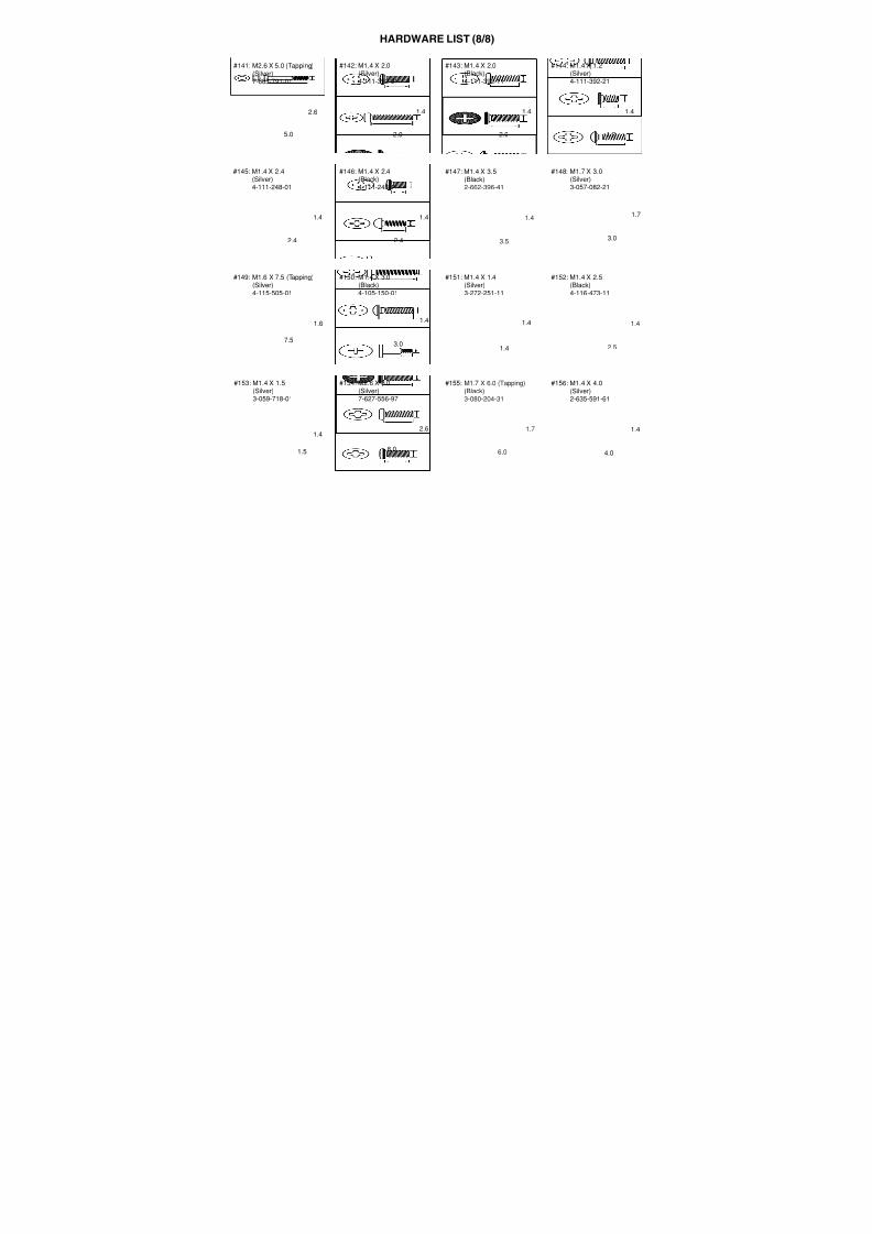
7/18/2019 SONY+HVR-HD1000 SERVICE MANUAL
http://slidepdf.com/reader/full/sonyhvr-hd1000-service-manual 408/425111
Q u i c k R e f
e r e n c e
N Tape transport indicator
O Video operation buttons (33)
P Data file name
Q Picture number/Total number ofrecorded pictures in the current
playback folder
R Playback folder (54)
S Previous/Next folder iconThe following indicators appear when the first
or last picture of the current folder is
displayed and when there are multiple folders
on the same “Memory Stick Duo.”
T Image delete button (73)
U Tape playback select button (34)
V Previous/Next image button (34)
W Index screen display button (34)
X Image protection mark (74)
Y Print mark (74)
Viewing movies
2 4 5
8
1
qg
qf
Viewing still images
: Touch to move to the previousfolder.
: Touch to move to the next folder.
: Touch / to move to eitherthe previous or the next folder.
MEMORY PLAY
6.1M
2 qj qk
ql
w;
8wa
wf wg
wdws
qh 0
Continued,
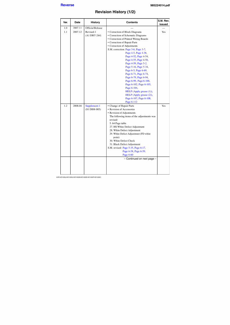
7/18/2019 SONY+HVR-HD1000 SERVICE MANUAL
http://slidepdf.com/reader/full/sonyhvr-hd1000-service-manual 409/425112
Upper left
Upper right
Center
Bottom
Indicators when you madechanges
Indicator Meaning
Recording format
(60)
Manual sound level
adjustment (61)
AUDIO MODE*
(60)
SP LP Recording mode*
(60)Self-timer recording
(50)
WIDE SELECT*
(60)
QUICK REC** (64)
Interval photo
recording (55)
Indicator Meaning
HDV input/
DV input (71)
HDV output/
DV output (37, 70)
i.LINK connection
(37, 70, 71)
Slide show (55)
120
+2
+3
Q.REC
Upper left Upper right
Bottom Center
M
Indicator Meaning
Color Slow Shutter
(49)
PictBridge
connecting (75)
EZ Warning (91)
NightShot (31)
Super NightShot
(49)
Indicator Meaning
AE SHIFT (47)
WB SHIFT (48)
Picture effect (57)
Digital effect (56)
9 Manual focus (48)
SCENE SELECT(45)
Sharpness (47)
. Backlight (32)
n White balance (46)
SteadyShot off (50)
Zebra (50)
Tele macro (49)CAMERA COLOR
(48)
CONV.LENS (51)
X.V.COLOR ** (51)
SPOT METER (46)/
EXPOSURE (46)
SHUTTR SPEED (47)
ZOOM by RING
SETTING(31)
* The settings can be made only for the pictures
in the DV format.
Indicators displayed during recording/playback (Continued)
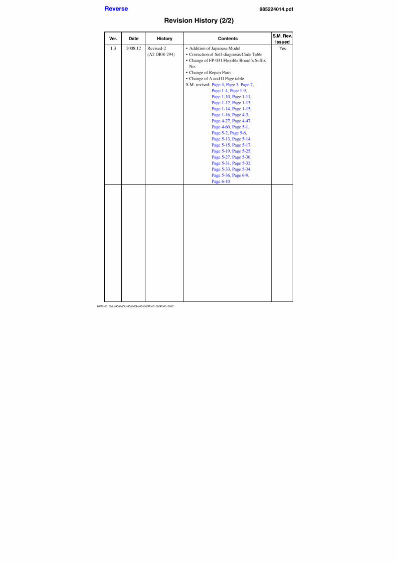
7/18/2019 SONY+HVR-HD1000 SERVICE MANUAL
http://slidepdf.com/reader/full/sonyhvr-hd1000-service-manual 410/425113
Q u i c k R e f
e r e n c e
b Notes
• Indicators and their positions are approximateand differ from what you actually see.
Other indicator
** The setting can be made only for the pictures in
the HDV format.
Indicator Meaning
Information (92)

7/18/2019 SONY+HVR-HD1000 SERVICE MANUAL
http://slidepdf.com/reader/full/sonyhvr-hd1000-service-manual 411/425114
Index
Numeric1080i/576i.............................62
12BIT....................................60
16BIT....................................60
21-pin adaptor.......................41
576i.......................................62
AAC Adaptor ..........................21
AE SHIFT.......................47, 89
ALL ERASE.........................53
AUDIO MIX ........................60
AUDIO MODE ....................60
AUTOSLW SHTR
(Auto slow shutter)...............47
AU.LVL DISP
(Audio level display)............61
A/V connecting cable .....38, 68
A/V OUT jack ......................37
BBACK LIGHT......................32
Battery ..................................21
BEACH ................................45
BEEP ....................................64
CCALIBRATION.................102
CAMERA COLOR ..............48
CAMERA DATA.................64
CAMERA SET menu...........45
CANDLE..............................45
Cassette...........................26, 95
Charging time .......................22
Cleaning cassette ................101
CLOCK SET ........................24
COLOR BAR .......................63
COLOR SLOW S (ColorSlow Shutter)............49, 86, 89
COMPONENT .....................62
COMPONENT OUT jack ....37
Component video cable ....... 38
Computer ............................. 77
CONV.LENS....................... 51
DDATA CODE ................ 24, 64
DATE/TIME................ 64, 110
Delete pictures ..................... 73
DIGITAL ZOOM .......... 50, 89
DISP OUTPUT
(Display output) ................... 64
Display indicators .............. 110
DOWN CONVERT ............. 62
Dual Rec .............................. 30
Dubbing ............................... 68
DV format............................ 59
DV SET................................ 60
D.EFFECT
(Digital effect)................ 56, 89
EEDIT/PLAY menu............... 58
END SEARCH .............. 36, 59
EXPOSURE................... 46, 89
FFADER .......................... 55, 89
FILE NO. (File number) ...... 53
FIREWORKS ...................... 45
FLASH (Flash motion)........ 56
FOCUS........................... 48, 86
FORMAT............................. 53
Frame-by-frame Playback.... 58
GGetting Started ..................... 18
GUIDEFRAME ................... 63
HHD (high definition)
image quality........................ 38
HDMI cable ..........................39
HDMI OUT jack ..................37
HDV format..........................59
HDV1080i ............................60HDV/DV Interface ...............37
HISTOGRAM ......................50
IImage protection...................74
Image size (IMAGE SIZE) ..52
INDOOR ..............................46
“InfoLITHIUM” battery
pack ......................................98
INT.REC-STL
(Interval photo recording) ....55
i.LINK ..................................99
i.LINK cable.............39, 69, 72
i.LINK CONV......................62
LLANDSCAPE ......................45
LANGUAGE........................65
LCD BL LEVEL
(LCD back light level)..........61
LCD BRIGHT ......................61
LCD COLOR .......................61
LCD/VF SET........................61
LP (Long Play) .....................60
MMacintosh .............................80
Maintenance and precautions ...........................95
MEMORY SET menu..........52
“Memory Stick” ...................96
“Memory Stick Duo” ...........26
FORMAT......................53
Menu.....................................42
MIC LEVEL.........................61
Mirror mode .........................32
Moisture condensation .......101
MONOTONE .......................55

7/18/2019 SONY+HVR-HD1000 SERVICE MANUAL
http://slidepdf.com/reader/full/sonyhvr-hd1000-service-manual 412/425115
Q u i c k R e f
e r e n c e
MOSAIC FADER.................55
N
NEG.ART .............................57 NEW FOLDER.....................54
NS LIGHT
(NightShot Light) .................49
NTSC ....................................94
Number of recordable pictures..................................52
O
OLD MOVIE........................56ONE PUSH...........................46
OUTDOOR...........................46
PPAL.................................87, 94
PASTEL................................57
PB FOLDER(Playback folder) ..................54
PB zoom ...............................35
Personal Menu ................42, 66
PICT.APPLI. menu
(Picture Application menu)...55
PICT.EFFECT
(Picture effect) ......................57
Playback................................33
Playing time..........................23
P-MENU....See Personal Menu
PORTRAIT (Soft portrait)....45
Power cord (Mains lead).......21
Print ......................................75
Print mark .............................74
QQUALITY.............................52
QUICK REC
(Quick recording)..................64
RREC CTRL(Recording control)...............71
REC FOLDER
(Recording folder)................ 54
REC MODE
(Recording mode) ................60
Rec review............................ 36
Recording .............................28
Recording time..................... 22
REMAINING....................... 64
Remaining battery ........22, 110
Reversal Playback ................ 58
RING....................................31
RING SETTING ..................51
SS VIDEO jack ..........37, 39, 68
SCENE SELECT ........... 45, 89
SD (standard definition)
image quality........................39
Searching for the starting
point .....................................36
SELF-TIMER.......................50
SEPIA................................... 57SHARPNESS................. 47, 89
SHUTTR SPEED .................47
SKINTONE..........................57
SLIDE SHOW......................55
SMTH SLW REC (Smoothslow recording) ..............57, 90
SNOW..................................45
SOLARIZE .......................... 57
SP (Standard Play) ...............60
Specifications ..................... 104
SPOT FOCUS................ 48, 89
SPOT METER
(Flexible spot meter) ...... 46, 89
SPOTLIGHT........................ 45
STANDARD........................ 52
STANDARD SET menu...... 59
STATUS CHECK ................63
STEADYSHOT .............50, 86
STILL...................................56
Still image ................ 29, 34, 52
STILL SET ...........................52
SUNRSE SUNSET(Sunrise and sunset)..............45
SUPER NS
(Super NightShot).................49
TTape counter .......................110
TELE MACRO...............49, 89
Time code ...........................110
TIME/LANGU. menu ..........65
TRAIL ..................................56
TV.........................................37TV color systems ..................94
TWILIGHT...........................45
UUSB SELECT.......................58
Using abroad.........................94
VVAR.SPD PB(Various speed playback) .....58
VCR HDV/DV .....................59
VF B.LIGHT
(Viewfinder brightness)........62
VF COLOR ..........................62
VIDEO OUT ........................62
VOLUME .............................61
WWarning indicators ...............91
Warning messages ................92
WB SHIFT
(White Balance Shift) ...........48
WHITE BAL.
(White balance) ..............46, 89
WHITE FADER ...................55
Windows.........................77, 78
WORLD TIME.....................65
Write-protect tab...................95
Continued,

7/18/2019 SONY+HVR-HD1000 SERVICE MANUAL
http://slidepdf.com/reader/full/sonyhvr-hd1000-service-manual 413/425116
XX.V.COLOR.................51, 100
ZZEBRA.................................50
Zoom ....................................30
Index (Continued)

7/18/2019 SONY+HVR-HD1000 SERVICE MANUAL
http://slidepdf.com/reader/full/sonyhvr-hd1000-service-manual 414/425
http://www.sony.net/
Printed on 70% or more recycled paperusing VOC (Volatile Organic Compound)-free vegetable oil based ink.
Printed in Japan
GB
Di gi t al HDV i d e
o C am er aR e c o
r d er

7/18/2019 SONY+HVR-HD1000 SERVICE MANUAL
http://slidepdf.com/reader/full/sonyhvr-hd1000-service-manual 415/425Sony EMCS Co.HVR-HD1000U/HD1000N/HD1000E/HD1000P/HD1000C
Sony EMCS Co.9-852-240-81
2008D0500-1 © 2008.4
Published by Kohda TEC
SERVICE MANUALUS Model Canadian Model
AEP Model E Model
Chinese Model
HVR-HD1000U/HD1000N/HD1000E/ HD1000P/HD1000C
SUPPLEMENT-1File this supplement with the service manual.
(DI08-005)
• Change of Repair Parts• Revision of Accessories• Revision of Adjustments
Ver. 1.2 2008.04
Note: Please refer to Ver. 1.2 of SERVICE MANUAL (9-852-240-12) for the revision of accessories and the revision of adjustments.
4-2. SCHEMATIC DIAGRAMS
VC-500 BOARD (23/23) (CONNECTOR)(Service manual page 4-29, Location E-10 to F-11)
4. PRINTED WIRING BOARDS AND SCHEMATIC DIAGRAMS
Former New
: Points changed portion.
16P
13
14
15
16
D1011
MAZS068G08S0
BATT/XEXT
REG_GND
R1009
1k
ACV_UNREG
ACV_UNREG
ACV_UNREG
BATT/XEXT
16P
13
14
15
16
D1011
XX
BATT/XEXT
REG_GND
R1009
1k
ACV_UNREG
ACV_UNREG
ACV_UNREG
BATT/XEXT

7/18/2019 SONY+HVR-HD1000 SERVICE MANUAL
http://slidepdf.com/reader/full/sonyhvr-hd1000-service-manual 416/425 — 2 —
HVR-HD1000U/HD1000N/HD1000E/HD1000P/HD1000C
& : Points added portion.
257 3-284-075-01 COVER, MICROPHONE HOLDER RUBBER
708 2-666-376-11 SCREW (1.4X1.0), POWER LOCK
5-1. EXPLODED VIEWS
Page Former New
Ref. No. Part No. Description Ref. No. Part No. Description
708 2-546-417-01 SCREW (M1.4)
5. REPAIR PARTS LIST
5-7
5-15
252 254
254
255
255
253
#102
#53
ns
ns 254
254
255
255
253
#102
#53
ns
ns
257
252
&
5-2. ELECTRICAL PARTS LIST
Page Former New
Ref. No. Part No. Description Ref. No. Part No. Description
HP-150 Board
< CONNECTOR >
* CN0604 1-580-789-22 PIN, CONNECTOR (SMD) 6P
MO-027 Board
< CONNECTOR >
* CN0504 1-817-555-51 CONNECTOR, FFC/FPC 8P
VC-500 Board
< CONNECTOR >
* CN4801 1-818-818-71 CONNECTOR, FPC (ZIF) 29P
* CN4803 1-817-829-71 CONNECTOR, FPC (ZIF) 27P
< DIODE >
* D1011 6-501-956-01 DIODE MAZS068G08S0
< FUSE >
0 F4601 1-576-406-21 FUSE, MICRO (1608) (1.4A/32V)
0 F4602 1-576-406-21 FUSE, MICRO (1608) (1.4A/32V)
0 F4603 1-576-406-21 FUSE, MICRO (1608) (1.4A/32V)
0 F4604 1-576-406-21 FUSE, MICRO (1608) (1.4A/32V)
0 F4605 1-576-406-21 FUSE, MICRO (1608) (1.4A/32V)
0 F4606 1-576-406-21 FUSE, MICRO (1608) (1.4A/32V)
0 F4607 1-576-406-21 FUSE, MICRO (1608) (1.4A/32V)
< IC >
* IC4401 6-807-924-01 IC MB91195ABGL-G-251-ERE1
HP-150 Board
< CONNECTOR >
CN0604 1-580-789-21 PIN, CONNECTOR (SMD) 6P
MO-027 Board
< CONNECTOR >
* CN0504 1-816-655-51 FFC/CONNECTOR, FPC (LIF) 8P
VC-500 Board
< CONNECTOR >
* CN4801 1-818-818-81 CONNECTOR, FPC (ZIF) 29P
* CN4803 1-817-829-81 CONNECTOR, FPC (ZIF) 27P
< DIODE >
< FUSE >
0F4601 1-576-406-11 FUSE (1.4A/32V)
0F4602 1-576-406-11 FUSE (1.4A/32V)
0F4603 1-576-406-11 FUSE (1.4A/32V)
0F4604 1-576-406-11 FUSE (1.4A/32V)
0F4605 1-576-406-11 FUSE (1.4A/32V)
0F4606 1-576-406-11 FUSE (1.4A/32V)
0F4607 1-576-406-11 FUSE (1.4A/32V)
< IC >
* IC4401 6-808-122-01 IC MB91195ABGL-G-257-ERE1
5-20
5-23
5-29
The components identified bymark 0 or dotted line withmark0 are critical for safety.Replace only with part numberspecified.
Les composants identifiés par unemarque 0 sont critiques pour lasécurité.Ne les remplacer que par une pièceportant le numéro spécifié.
5-30

7/18/2019 SONY+HVR-HD1000 SERVICE MANUAL
http://slidepdf.com/reader/full/sonyhvr-hd1000-service-manual 417/425
HARDWARE LIST (1/8)
#1: M1.7 X 2.5(Black)2-635-562-11
2.5
1.7
#10:M1.7 X 4.0(Silver)2-599-475-31
1.6
1.7
#6: M1.4 X 1.7(Silver)2-598-474-01
1.7
1.4
#7: M1.7 X 1.6(Black)7-627-552-18
#3: M1.7 X 2.5(Red)2-660-401-01
2.5
1.7
#2: M1.7 X 4.0(Black)2-635-562-31
4.0
1.7
4.0
1.7
#5: M1.7 X 3.5 (Tapping)(Black)3-080-204-01
3.5
1.7
#4: M1.4 X 2.5 (Tapping)(Dark Silver)3-348-998-81
2.5
1.4
#12: M1.7 X 5.0 (Tapping)(Black)3-080-204-21
1.7
#9: M1.7 X 5.0 (Tapping)(Silver)3-078-890-21
5.0
1.7
#14:M1.7 X 2.5(Silver)2-599-475-11
#13: M1.7 X 2.5 (Tapping)(Silver)3-085-397-01
2.5
1.7
#11: M1.7 X 4.0 (Tapping)(Silver)3-078-890-11
#8: M1.7 X 3.5 (Tapping)(Silver)3-078-890-01
3.5
1.7
4.0
1.7
5.0
2.5
#17:M1.7 X 1.5(Silver)2-586-389-01
2.5
1.7
#15:M1.4 X 1.5(Silver)3-062-214-01
1.5
1.4 1.4
#16:M1.4 X 2.5(Silver)2-586-337-01
1.5
3.5
1.7 2.2
#18:M1.4 X 2.5(Silver)2-635-591-21
2.5
1.4
#19: M1.2 X 4.0 (Tapping)(Red)3-086-156-21
4.0
1.2
#20:M1.4 X 3.0(Silver)2-635-591-31
3.0
1.4

7/18/2019 SONY+HVR-HD1000 SERVICE MANUAL
http://slidepdf.com/reader/full/sonyhvr-hd1000-service-manual 418/425
HARDWARE LIST (2/8)
#21:M1.4 X 3.0(Black)2-662-396-21
3.0
1.4
#22: M1.7 X 5.0 (Tapping)(Silver)3-083-261-01
1.7
5.0
1.7
5.5
#23: M1.7 X 4.0 (Tapping)(Black)3-080-204-11
4.0
1.7
#24: B1.7 X 5.5 (Tapping)(Black)4-679-805-11
#25:M1.7 X 3.0(Black)2-635-562-21
3.0
1.7
#26:M1.4 X 2.0(Silver)2-635-591-11
2.0
1.4
#27:M1.4 X 2.0(Black)2-662-396-11
2.0
1.4
#28: M1.4 X 4.0 (Tapping)(Silver)3-348-998-61
1.4
4.0
#29:M1.4 X 2.5(Black)2-662-396-01
#31:M3.0 X 4.0(Silver)2-102-434-01
2.5
1.4
#30: M1.2 X 3.5 (Tapping)(White)3-086-156-11
3.5
1.2
#32: M2.0 X 4.5 (Tapping)(Silver)2-102-498-01
#33:M3.0 X 6.0(Silver)3-077-331-21
#35: M4.0 X 6.0 (Tapping)(Silver)3-975-291-02
#34:M3.0 X 8.0(Black)3-077-331-41
#36:M3.0 X 6.0(Silver)4-886-821-11
#37: M2.0 X 6.0 (Tapping)(Black)3-080-206-31
#38: M3.0 X 20.0 (Tapping)(Silver)7-685-651-79
#40: M2.0 X 4.0 (Tapping)(Silver)7-685-851-04
#39: M2.6 X 5.0 (Tapping)(Black)7-685-791-09
4.0
3.0
4.5
2.0
6.0
3.0
8.0
3.0 4.0
6.0 6.0
3.0
6.0
2.0
20.0
3.0
4.0
2.0
5.0
2.6

7/18/2019 SONY+HVR-HD1000 SERVICE MANUAL
http://slidepdf.com/reader/full/sonyhvr-hd1000-service-manual 419/425
HARDWARE LIST (3/8)
#41: M3.0 X 8.0 (Tapping)(Silver)3-065-748-01
8.0
3.0
#42: M2.0 X 4.0 (Tapping)(Silver)7-628-253-00
2.0
4.0
#43:M1.7 X 4.0(Red)2-660-401-31
4.0
1.7
#46:M1.7 X 3.0(Red)2-660-401-11
#45:M1.4 X 2.5(Silver)2-587-151-01
#47: M1.4 X 3.0 (Tapping)(Silver)2-665-774-01
3.0
1.4
#44: M1.7 X 3.0 (Tapping)(Silver)3-078-890-61
3.0
1.7
3.0
1.7
2.5
1.4
#48:M1.7 X 2.5(Silver)3-973-497-91
2.5
1.7
#49:M2.0 X 4.0(Black)2-630-005-31
#50:M2.0 X 3.0(Red)2-891-494-11
#51:M2.0 X 2.5(Silver)3-073-686-01
#54: M1.75 X 6.0 (Tapping)(Black)3-318-203-11
#53: M2.0 X 5.0 (Tapping)(Black)3-080-206-21
#55:M2.0 X 4.0(Silver)2-655-582-11
#52: M2.0 X 4.0 (Tapping)(Black)3-080-206-11
#56:M2.0 X 3.5(Silver)3-067-187-11
4.0
2.0
3.0
2.0
2.5
2.0
5.0
2.0
4.0
2.0
6.0
1.75
4.0
2.0
3.5
2.0
#57:M1.7 X 4.0(Black)7-627-852-18
4.0
1.7
#58: M2.0 X 6.0 (Tapping)(Silver)3-719-408-11
6.0
2.0
#59: M2.0 X 5.0 (Tapping)(Silver)3-080-205-21
#60:M2.6 X 5.0(Black)3-061-062-11
5.0
2.0
5.0
2.6

7/18/2019 SONY+HVR-HD1000 SERVICE MANUAL
http://slidepdf.com/reader/full/sonyhvr-hd1000-service-manual 420/425
HARDWARE LIST (4/8)
#61:M3.0 X 10.0(Black)7-682-549-09
10.0
3.0
#62:M2.0 X 3.0(Silver)3-080-202-21
3.0
2.0
#63:M5.0 X 12.5(Black)3-060-811-21
12.5
5.0
#64: M1.7 X 5.0 (Tapping)(Silver)2-666-551-21
5.0
1.7
#65:M1.4 X 3.5(Silver)2-635-591-01
3.5
1.4
#66:M1.4 X 1.4(Silver)2-635-591-41
1.4
1.4
#71:M1.4 X 2.0(Red)3-208-537-01
2.0
1.4
2.0
1.4
2.0
1.4
#67:M1.4 X 2.0(Silver)3-389-523-16
2.0
1.4
#68:M1.7 X 4.0(Silver)2-655-581-01
4.0
1.7
#72:M1.4 X 2.0(Silver)4-663-621-41
2.0
1.4
#69:M1.7 X 3.0(Silver)2-599-475-21
3.0
1.7
#70:M1.7 X 5.0(Silver)2-599-475-41
5.0
1.7
#75: M1.7 X 3.5 (Tapping)(Silver)2-666-551-01
#76: M1.7 X 4.0 (Tapping)(Silver)2-666-551-11
#73: M1.2 X 4.0 (Tapping)(Black)3-086-156-61
#74: M1.7 X 6.0 (Tapping)(Silver)2-666-551-31
#78:M1.4 X 3.5(Red)3-208-537-11
#79:M1.4X 2.0(Silver)2-587-151-11
#80:M1.4X 2.0(Black)3-279-411-01
6.0
1.7
3.5
1.7
4.0
1.7
4.0
1.2
#77: M1.2 X 5.0 (Tapping)(Silver)3-086-156-31
5.0
1.2
3.5
1.4

7/18/2019 SONY+HVR-HD1000 SERVICE MANUAL
http://slidepdf.com/reader/full/sonyhvr-hd1000-service-manual 421/425
HARDWARE LIST (5/8)
#81:M1.7 X 2.5(Silver)2-515-756-01
2.5
1.7
#82:M1.4 X 1.4(Silver)3-272-251-01
1.4
1.4
#83: M1.7 X 7.0 (Tapping)(Black)3-080-204-41
#84:M2.0 X 3.0(Silver)3-072-453-11
#85:M1.7 X 2.5(Black)2-515-483-11
#86: M1.7 X 4.0 (Tapping)(Silver)2-695-434-21
4.0
1.7
#87:M1.6 X 5.3(Black)2-689-328-01
5.3
1.6
#88: M1.6 X 5.9 (Tapping)(Silver)2-689-015-01
5.9
1.6
#89: M2.0 X 5.5 (Tapping)(Silver)2-695-575-01
5.0
2.0
#90:M1.7 X 3.0(Silver)3-271-395-01
3.0
1.7
#91: M1.7 X 3.0 (Tapping)(Silver)2-695-434-11
#92:M2.0 X 3.9(Black)3-268-954-01
3.9
2.0
#93: M1.7 X 3.5 (Tapping)(Silver)3-254-082-01
#94:M1.7 X 4.0(Black)2-515-483-31
1.7
7.0 3.0
2.0
2.5
1.7
4.0
1.7
3.5
1.7
3.5
1.7
#95:M3.0 X 8.0 (Tapping) (Black)7-685-646-79
8.0
3.0
#99:M2.5 X 6.0 (Tapping) (Silver)3-776-750-02
6.0
2.5
#96:M1.4 X 2.5(Silver)2-587-151-21
2.5
1.4
#97:M1.4 X 2.5(Black)2-662-396-31
2.5
1.4
#98:M3.0 X 8.0(Silver)3-077-331-01
8.0
3.8
#100: M2.0 X 6.0(Black)3-080-203-51
6.0
2.0

7/18/2019 SONY+HVR-HD1000 SERVICE MANUAL
http://slidepdf.com/reader/full/sonyhvr-hd1000-service-manual 422/425
HARDWARE LIST (6/8)
#101: M2.0 X 5.0(Silver)7-621-555-39
5.0
2.0
#107: M2.0 X 5.0(Silver)3-032-750-01
5.0
2.0
#108: M1.7 X 3.0 (Tapping)(Black)2-695-430-01
#111: M1.7 X 4.0 (Tapping)(Black)2-887-124-01
#102: M2.6 X 8.0(Black)7-621-284-30
8.0
2.6
#105: M2.0 X 4.0(Red)2-891-494-31
#106: M2.0 X 6.0(Black)3-713-786-11
#103: M2.6 X 10.0(Silver)7-685-794-09
10.0
2.6
#104: M3.0 X 8.0(Black)7-682-548-09
8.0
3.0
6.0
2.6
4.0
2.0
6.0
2.0
3.0
1.7
#109: M1.7 X 3.0(Black)2-515-483-21
3.0
1.7
3.0
2.0
#110: M2.0 X 3.0(Black)2-630-005-21
4.0
1.7
#114: M2.0 X 5.5 (Tapping)(Silver)2-698-464-01
5.5
2.0
#112: M1.4 X 5.0(Black)2-178-410-11
5.0
1.4
#113: M1.7 X 5.0(Black)2-635-562-41
5.0
1.7
#115: M1.4 X 3.5 (Tapping)(Silver)3-348-998-51
1.4
3.5
#116: M2.0 X 3.5 (Tapping)(Silver)2-695-435-01
3.5
2.0
#117: M1.7 X 4.5 (Tapping)(Silver)2-695-429-31
#118: M1.4 X 2.0(Black)2-655-580-01
4.5
1.7
2.0
1.4
#119: M2.6 X 5.0(Black)7-627-556-58
5.0
2.6
#120: M2.6 X 6.0(Silver)7-621-770-67

7/18/2019 SONY+HVR-HD1000 SERVICE MANUAL
http://slidepdf.com/reader/full/sonyhvr-hd1000-service-manual 423/425
HARDWARE LIST (7/8)
#121: M2.0 X 4.0 (Tapping)(Silver)3-080-205-11
#123: M4.0 X 8.0(Black)7-682-561-09
8.0
4.0
6.0
3.0
#122: M3.0 X 6.0(Black)7-682-547-09
#125: M1.4 X 3.0 (Black)3-291-847-01
#129: M3.0 X 12.0(Black)7-682-550-09
4.0
2.0
2.0
12.0
1.7
4.0
#124: M1.7 X 2.0 (Silver)2-599-475-01
#126: M2.9 X 3.5 (Black)3-292-616-01
#134: M2.6 X 7.0(Black)3-299-572-01
#133: M3.0 X 6.0(Black)3-452-484-01
#131: M4.0 X 12.0(Silver)3-452-471-01
#130: M2.0 X 4.5 (Tapping)(Silver)3-732-817-11
#132: M2.6 X 6.0(Black)4-673-655-01
#127: M3.0 X 25.0 (Black)7-682-654-09
#128: M4.0 X 12.0 (Black)3-452-472-01
3.0
3.5
6.0
25.0
1.4 2.9 3.04.0
12.0
3.0
#135: M2.0 X 2.5(Black)7-627-553-28
2.57.0
12.06.0
6.0
2.02.6
4.0 2.6
3.0
4.5
2.0
#136: M1.4 X 4.0 (Tapping)(Black)3-065-509-11
#137: M1.7 X 3.0(Black)3-090-976-62
4.0
1.4
3.0
1.7
#138: M1.4 X 3.5(Silver)4-104-078-01
3.5
1.4
#139: M1.4 X 2.0(Silver)2-655-579-01
#140: M1.7 X 2.0(Black)2-635-562-01
2.0
1.4
2.0
1.7

7/18/2019 SONY+HVR-HD1000 SERVICE MANUAL
http://slidepdf.com/reader/full/sonyhvr-hd1000-service-manual 424/425
HARDWARE LIST (8/8)
5.0
2.6
#141: M2.6 X 5.0 (Tapping)(Silver)7-685-791-01
#142: M1.4 X 2.0(Silver)4-111-392-01
2.0
1.4
#143: M1.4 X 2.0(Black)4-111-392-11
2.0
1.4
#144: M1.4 X 1.2(Silver)4-111-392-21
1.2
1.4
#145: M1.4 X 2.4(Silver)4-111-248-01
2.4
1.4
#146: M1.4 X 2.4(Black)4-111-248-11
2.4
1.4
3.5
1.4
#147: M1.4 X 3.5(Black)2-662-396-41
#148: M1.7 X 3.0(Silver)3-057-082-21
3.0
1.7
#149: M1.6 X 7.5 (Tapping)(Silver)4-115-505-01
#153: M1.4 X 1.5(Silver)3-059-718-01
7.5
1.6
#150: M1.4 X 3.0(Black)4-105-150-01
3.0
1.4
2.5
1.4
#152: M1.4 X 2.5(Black)4-116-473-11
#151: M1.4 X 1.4(Silver)3-272-251-11
1.4
1.4
1.5
1.4
8.0
2.6
#154: M2.6 X 8.0(Silver)7-627-556-97
1.7
6.0
#155: M1.7 X 6.0 (Tapping) (Black)3-080-204-31
4.0
1.4
#156: M1.4 X 4.0(Silver)2-635-591-61

7/18/2019 SONY+HVR-HD1000 SERVICE MANUAL
http://slidepdf.com/reader/full/sonyhvr-hd1000-service-manual 425/425
Revision History (1/2)
Reverse
Ver.
1.0
1.1
1.2
Date
2007.11
2007.12
2008.04
History
Official Release
Revised-1(A1 DI07-244)
Supplement-1
(S1 DI08-005)
Contents
—
• Correction of Block Diagrams• Correction of Schematic Diagrams
• Correction of Printed Wiring Boards
• Correction of Repair Parts
• Correction of Adjustments
S.M. correction: Page 3-6, Page 3-7,
Page 4-5, Page 4-36,
Page 4-52, Page 4-54,
Page 4-55, Page 4-58,
Page 4-59, Page 5-2,
Page 5-16, Page 5-34,
Page 6-5, Page 6-69,
Page 6-71, Page 6-74,
Page 6-79, Page 6-94,
Page 6-99, Page 6-100,
Page 6-102, Page 6-103,
Page 6-104,
HELP (Apply grease (1)),
HELP (Apply grease (2)),
Page 6-107, Page 6-108,
Page 6-112
• Change of Repair Parts
• Revision of Accessories
• Revision of Adjustments
The following items of the adjustments was
revised:
5. 64 Page table
S.M. Rev.
issued
—
Yes
Yes
985224014.pdf