Embed Size (px)
Citation preview
2/9/2010
Sonnet 12 & Sonnet Lite
Shawn Carpenter
Sonnet Software, Inc.
100 Elwood Davis Road
North Syracuse, NY 13212
315-453-3096
http://www.sonnetsoftware.com
2/9/2010 © 2010 Sonnet Software, Inc www.sonnetsoftware.com
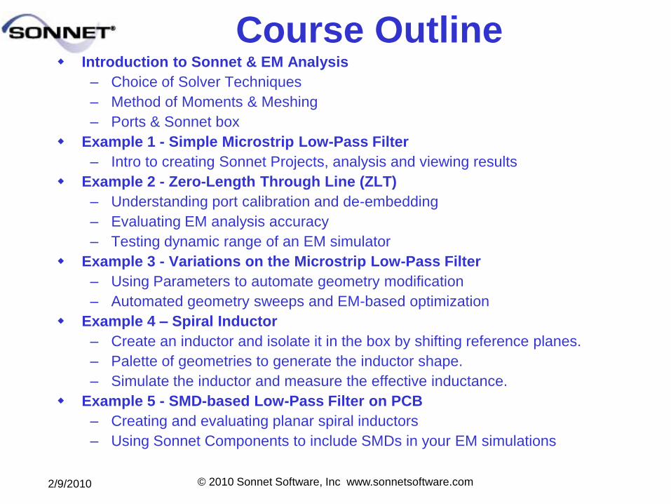
Course Outline Introduction to Sonnet & EM Analysis
– Choice of Solver Techniques
– Method of Moments & Meshing
– Ports & Sonnet box
Example 1 - Simple Microstrip Low-Pass Filter
– Intro to creating Sonnet Projects, analysis and viewing results
Example 2 - Zero-Length Through Line (ZLT)
– Understanding port calibration and de-embedding
– Evaluating EM analysis accuracy
– Testing dynamic range of an EM simulator
Example 3 - Variations on the Microstrip Low-Pass Filter
– Using Parameters to automate geometry modification
– Automated geometry sweeps and EM-based optimization
Example 4 – Spiral Inductor
– Create an inductor and isolate it in the box by shifting reference planes.
– Palette of geometries to generate the inductor shape.
– Simulate the inductor and measure the effective inductance.
Example 5 - SMD-based Low-Pass Filter on PCB
– Creating and evaluating planar spiral inductors
– Using Sonnet Components to include SMDs in your EM simulations
2/9/2010 © 2010 Sonnet Software, Inc www.sonnetsoftware.com
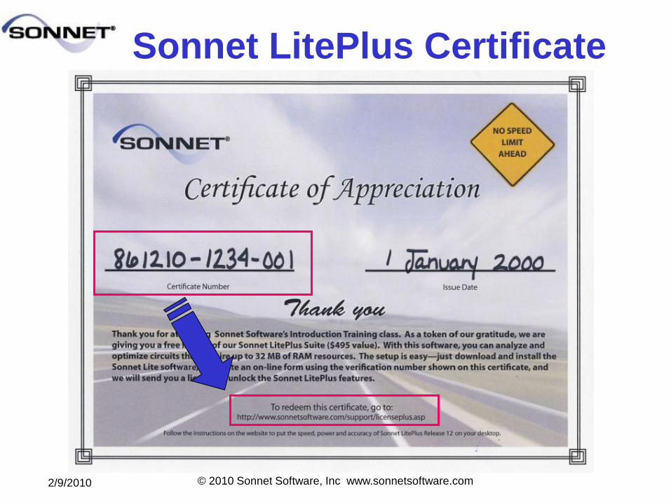
Sonnet LitePlus Certificate
2/9/2010 © 2010 Sonnet Software, Inc www.sonnetsoftware.com
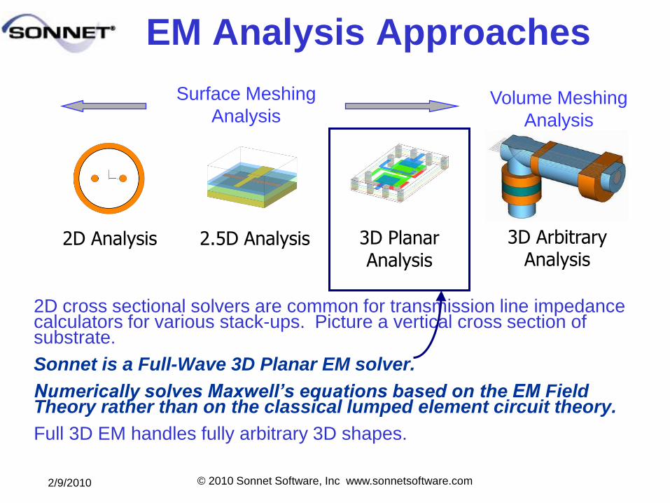
2D cross sectional solvers are common for transmission line impedance calculators for various stack-ups. Picture a vertical cross section of substrate.
Sonnet is a Full-Wave 3D Planar EM solver.
Numerically solves Maxwell’s equations based on the EM Field Theory rather than on the classical lumped element circuit theory.
Full 3D EM handles fully arbitrary 3D shapes.
2D Analysis 2.5D Analysis 3D Planar Analysis
3D Arbitrary Analysis
EM Analysis Approaches
Surface Meshing
AnalysisVolume Meshing
Analysis
2/9/2010 © 2010 Sonnet Software, Inc www.sonnetsoftware.com
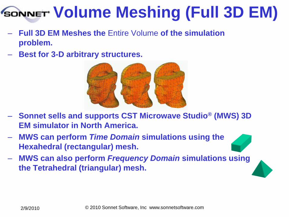
Volume Meshing (Full 3D EM)– Full 3D EM Meshes the Entire Volume of the simulation
problem.
– Best for 3-D arbitrary structures.
– Sonnet sells and supports CST Microwave Studio® (MWS) 3D
EM simulator in North America.
– MWS can perform Time Domain simulations using the
Hexahedral (rectangular) mesh.
– MWS can also perform Frequency Domain simulations using
the Tetrahedral (triangular) mesh.
2/9/2010 © 2010 Sonnet Software, Inc www.sonnetsoftware.com
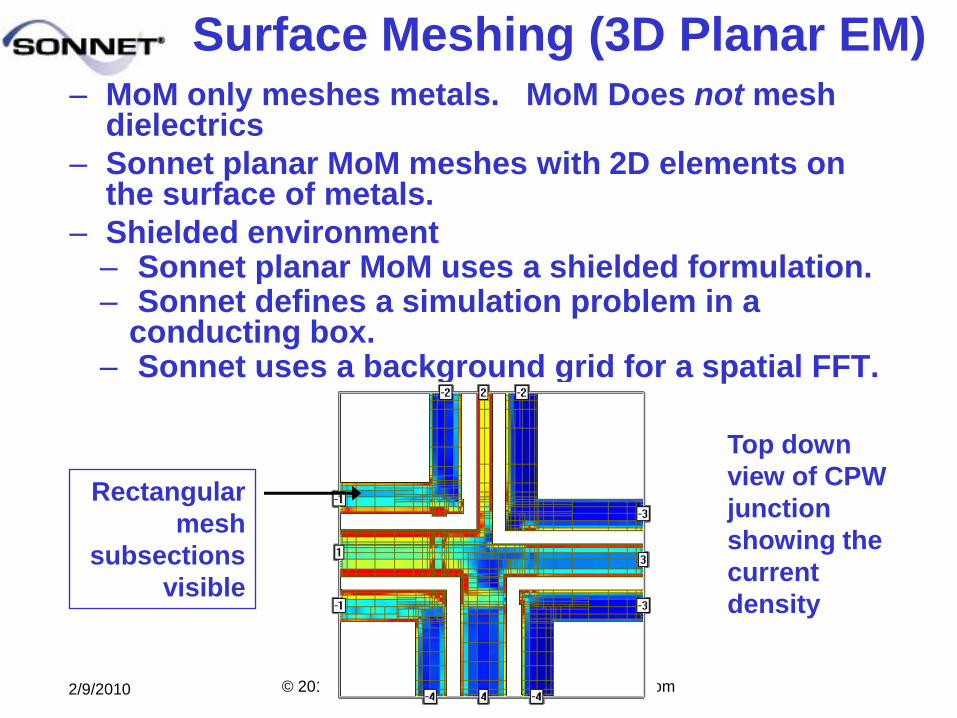
Surface Meshing (3D Planar EM)– MoM only meshes metals. MoM Does not mesh
dielectrics
– Sonnet planar MoM meshes with 2D elements on the surface of metals.
– Shielded environment– Sonnet planar MoM uses a shielded formulation. – Sonnet defines a simulation problem in a
conducting box. – Sonnet uses a background grid for a spatial FFT.
Top down
view of CPW
junction
showing the
current
density
Rectangular
mesh
subsections
visible
2/9/2010 © 2010 Sonnet Software, Inc www.sonnetsoftware.com
– Sonnet’s simulator technique performs
electromagnetic analysis for arbitrary 3D planar (e.g.,
microstrip, coplanar, stripline, etc.) geometries,
maintaining full accuracy at all frequencies.
– em, the simulator, is “full-wave” in that it takes into
account all possible coupling mechanisms.
– The analysis inherently includes dispersion, stray
coupling, discontinuities, surface waves, moding,
metallization loss, dielectric loss and radiation loss.
– Since em uses a surface meshing technique, i.e. it
meshes only the surface of the circuit metallization,
em can analyze predominately planar circuits much
faster than volume meshing techniques.
Sonnet
2/9/2010 © 2010 Sonnet Software, Inc www.sonnetsoftware.com
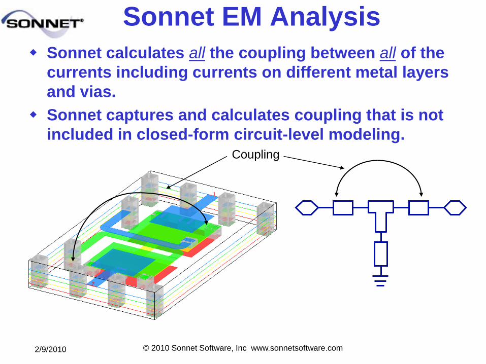
Sonnet EM Analysis
Sonnet calculates all the coupling between all of the
currents including currents on different metal layers
and vias.
Sonnet captures and calculates coupling that is not
included in closed-form circuit-level modeling. Coupling
2/9/2010 © 2010 Sonnet Software, Inc www.sonnetsoftware.com
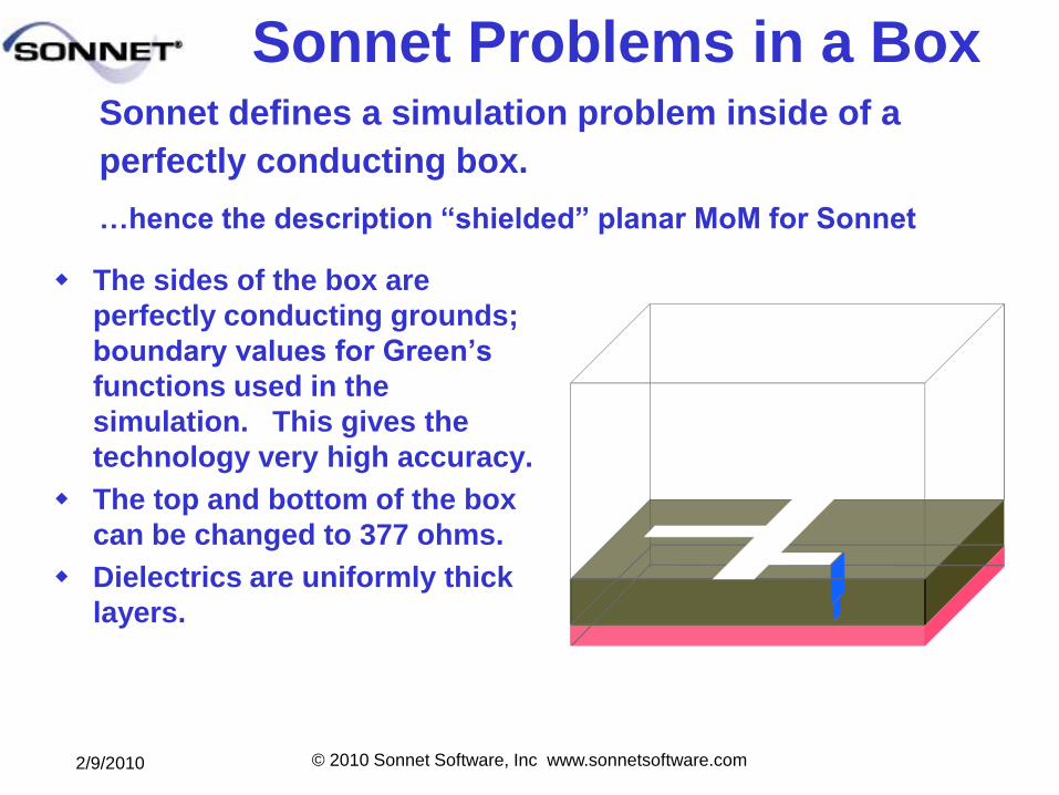
Sonnet Problems in a Box
The sides of the box are
perfectly conducting grounds;
boundary values for Green’s
functions used in the
simulation. This gives the
technology very high accuracy.
The top and bottom of the box
can be changed to 377 ohms.
Dielectrics are uniformly thick
layers.
Sonnet defines a simulation problem inside of a
perfectly conducting box.
…hence the description ―shielded‖ planar MoM for Sonnet
2/9/2010 © 2010 Sonnet Software, Inc www.sonnetsoftware.com
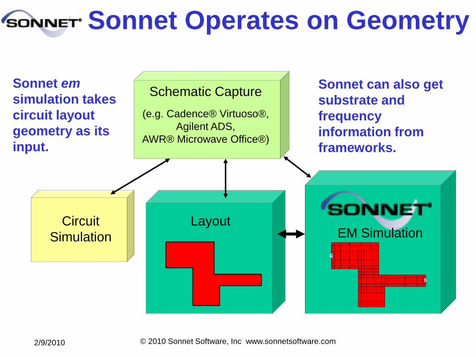
Sonnet Operates on Geometry
Sonnet em
simulation takes
circuit layout
geometry as its
input.
Schematic Capture
(e.g. Cadence® Virtuoso®,
Agilent ADS,
AWR® Microwave Office®)
Circuit
Simulation
LayoutEM Simulation
Sonnet can also get
substrate and
frequency
information from
frameworks.
2/9/2010 © 2010 Sonnet Software, Inc www.sonnetsoftware.com
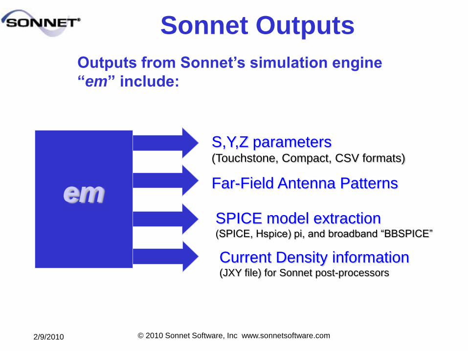
Sonnet Outputs
em
S,Y,Z parameters(Touchstone, Compact, CSV formats)
Far-Field Antenna Patterns
SPICE model extraction(SPICE, Hspice) pi, and broadband “BBSPICE”
Current Density information(JXY file) for Sonnet post-processors
Outputs from Sonnet’s simulation engine
―em‖ include:
2/9/2010 © 2010 Sonnet Software, Inc www.sonnetsoftware.com
1+-
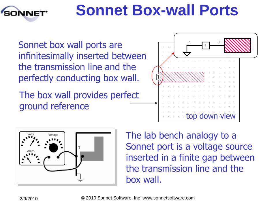
Sonnet Box-wall Ports
The box wall provides perfect ground reference
Sonnet box wall ports are infinitesimally inserted between the transmission line and the perfectly conducting box wall.
top down view
The lab bench analogy to a Sonnet port is a voltage source inserted in a finite gap between the transmission line and the box wall.
2/9/2010 © 2010 Sonnet Software, Inc www.sonnetsoftware.com
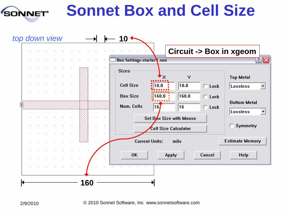
Sonnet Box and Cell Size
160
10
Circuit -> Box in xgeom
top down view
2/9/2010 © 2010 Sonnet Software, Inc www.sonnetsoftware.com
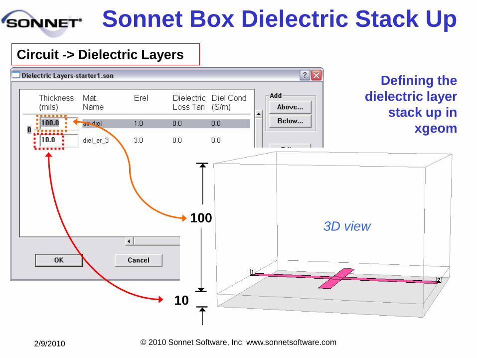
Sonnet Box Dielectric Stack Up
Circuit -> Dielectric Layers
10
1003D view
Defining the
dielectric layer
stack up in
xgeom
2/9/2010 © 2010 Sonnet Software, Inc www.sonnetsoftware.com
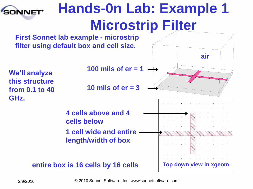
10 mils of er = 3
100 mils of er = 1
air
First Sonnet lab example - microstrip
filter using default box and cell size.
1 cell wide and entire
length/width of box
4 cells above and 4
cells below
Top down view in xgeomentire box is 16 cells by 16 cells
We’ll analyze
this structure
from 0.1 to 40
GHz.
Hands-0n Lab: Example 1
Microstrip Filter
2/9/2010 © 2010 Sonnet Software, Inc www.sonnetsoftware.com
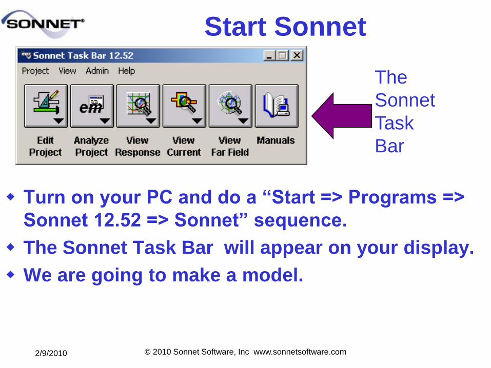
Start Sonnet
Turn on your PC and do a ―Start => Programs =>
Sonnet 12.52 => Sonnet‖ sequence.
The Sonnet Task Bar will appear on your display.
We are going to make a model.
The
Sonnet
Task
Bar
2/9/2010 © 2010 Sonnet Software, Inc www.sonnetsoftware.com
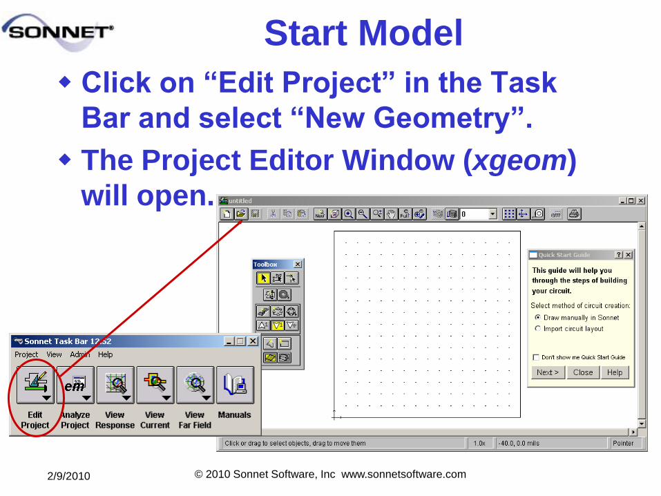
Start Model
Click on ―Edit Project‖ in the Task
Bar and select ―New Geometry‖.
The Project Editor Window (xgeom)
will open.
2/9/2010 © 2010 Sonnet Software, Inc www.sonnetsoftware.com
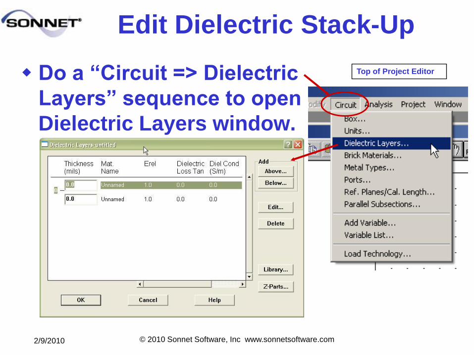
Edit Dielectric Stack-Up
Do a ―Circuit => Dielectric
Layers‖ sequence to open
Dielectric Layers window.
Top of Project Editor
2/9/2010 © 2010 Sonnet Software, Inc www.sonnetsoftware.com
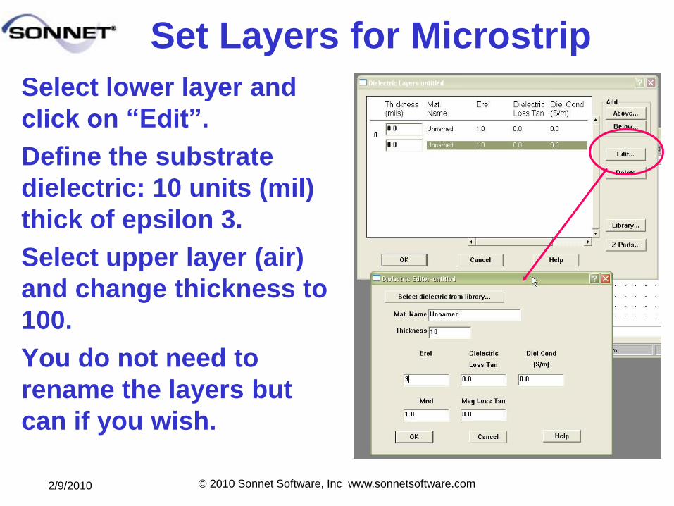
Set Layers for Microstrip
Select lower layer and
click on ―Edit‖.
Define the substrate
dielectric: 10 units (mil)
thick of epsilon 3.
Select upper layer (air)
and change thickness to
100.
You do not need to
rename the layers but
can if you wish.
2/9/2010 © 2010 Sonnet Software, Inc www.sonnetsoftware.com
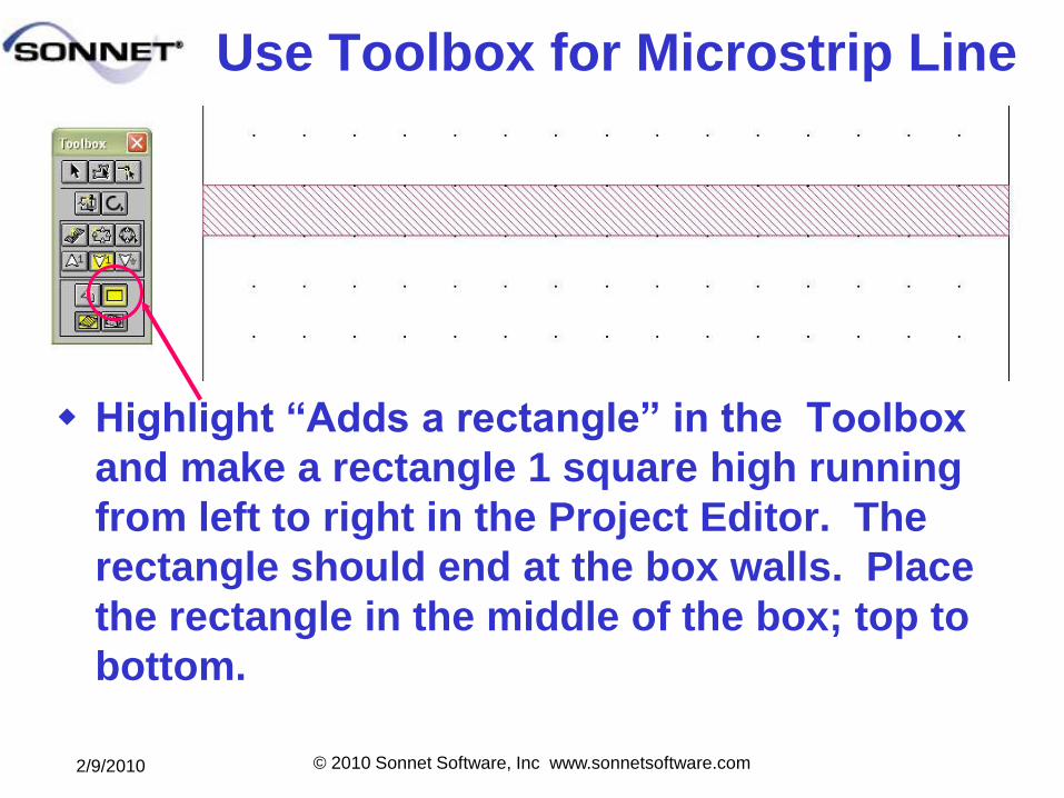
Use Toolbox for Microstrip Line
Highlight ―Adds a rectangle‖ in the Toolbox
and make a rectangle 1 square high running
from left to right in the Project Editor. The
rectangle should end at the box walls. Place
the rectangle in the middle of the box; top to
bottom.
2/9/2010 © 2010 Sonnet Software, Inc www.sonnetsoftware.com
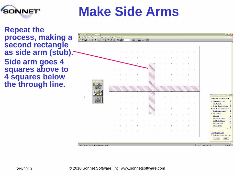
Make Side Arms
Repeat the process, making a second rectangle as side arm (stub).
Side arm goes 4 squares above to 4 squares below the through line.
2/9/2010 © 2010 Sonnet Software, Inc www.sonnetsoftware.com
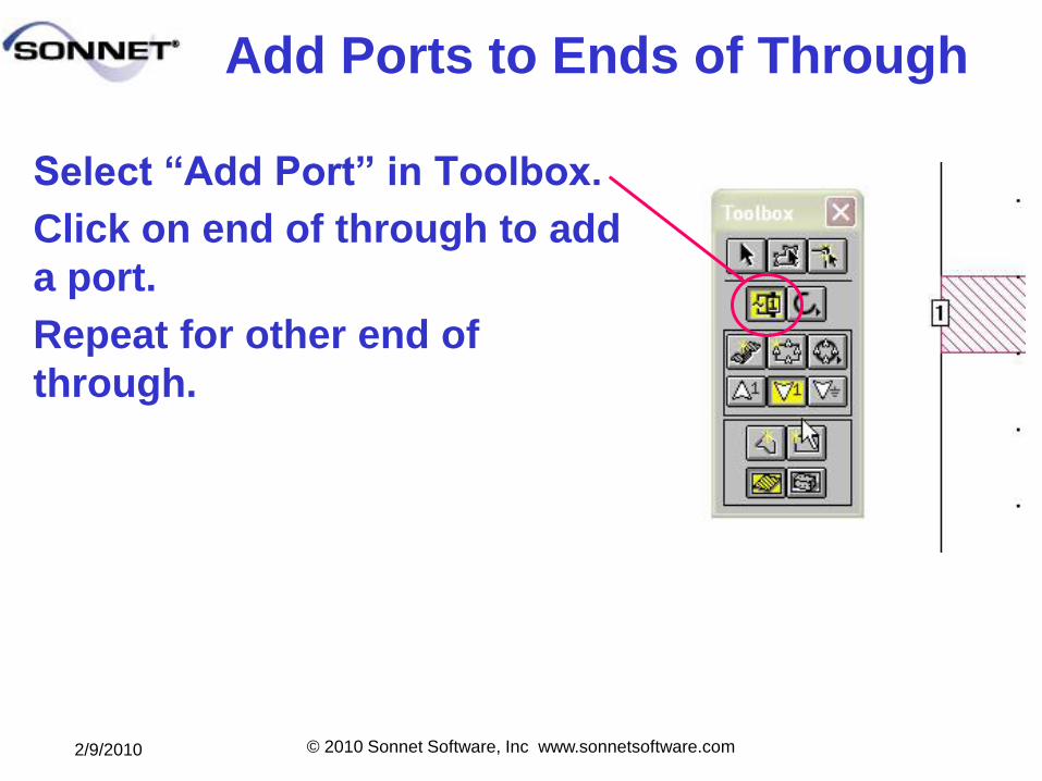
Add Ports to Ends of Through
Select ―Add Port‖ in Toolbox.
Click on end of through to add
a port.
Repeat for other end of
through.
2/9/2010 © 2010 Sonnet Software, Inc www.sonnetsoftware.com
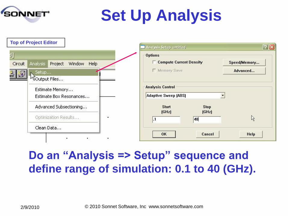
Set Up Analysis
Do an ―Analysis => Setup‖ sequence and
define range of simulation: 0.1 to 40 (GHz).
Top of Project Editor
2/9/2010 © 2010 Sonnet Software, Inc www.sonnetsoftware.com
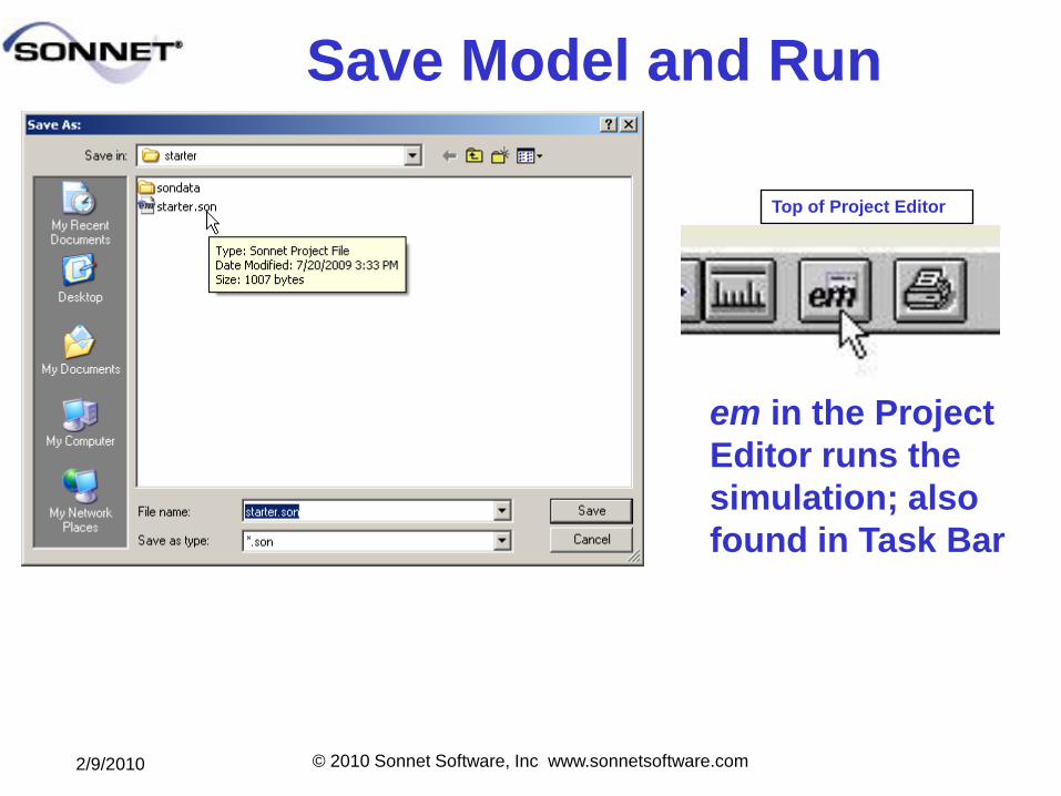
Save Model and Run
em in the Project
Editor runs the
simulation; also
found in Task Bar
Top of Project Editor
2/9/2010 © 2010 Sonnet Software, Inc www.sonnetsoftware.com
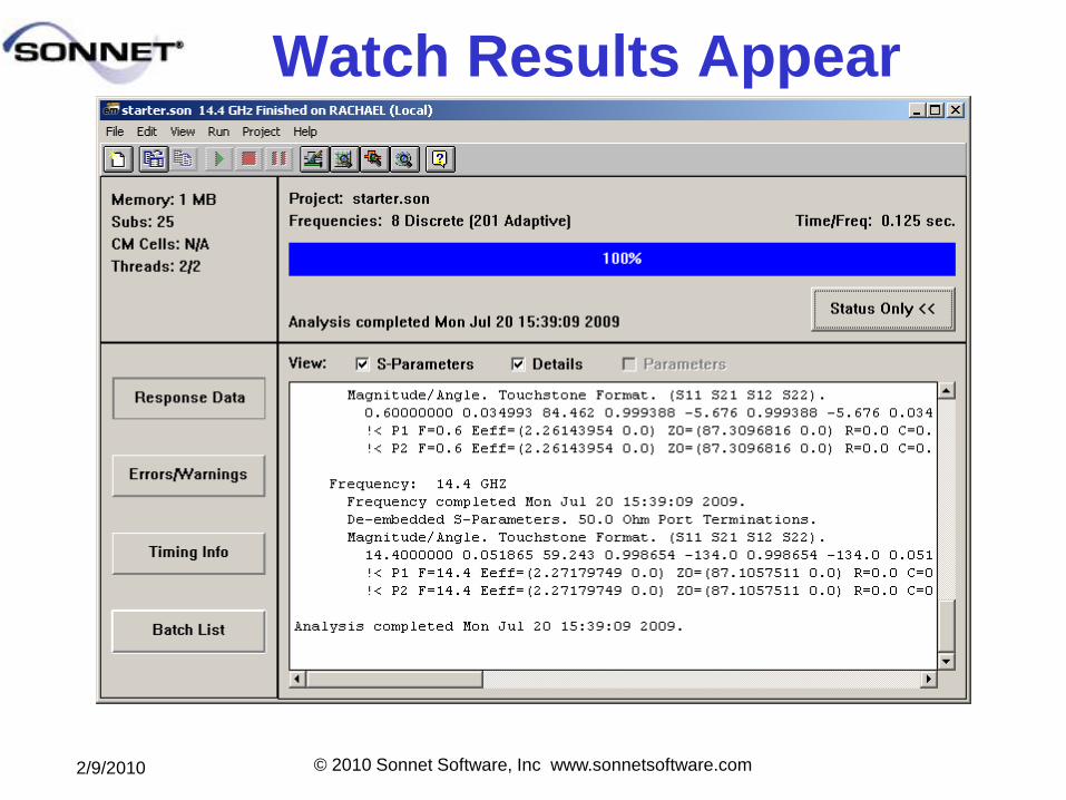
Watch Results Appear
2/9/2010 © 2010 Sonnet Software, Inc www.sonnetsoftware.com
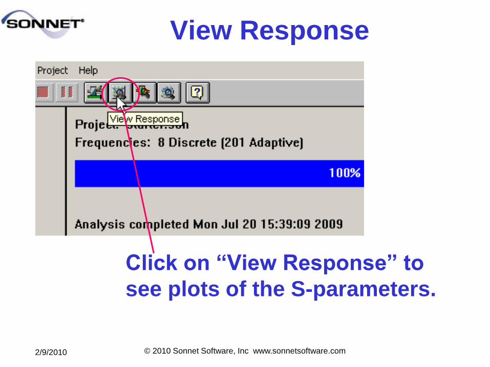
View Response
Click on ―View Response‖ to
see plots of the S-parameters.
2/9/2010 © 2010 Sonnet Software, Inc www.sonnetsoftware.com
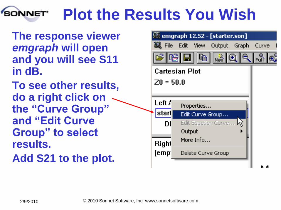
Plot the Results You Wish
The response viewer emgraph will open and you will see S11 in dB.
To see other results, do a right click on the ―Curve Group‖ and ―Edit Curve Group‖ to select results.
Add S21 to the plot.
2/9/2010 © 2010 Sonnet Software, Inc www.sonnetsoftware.com
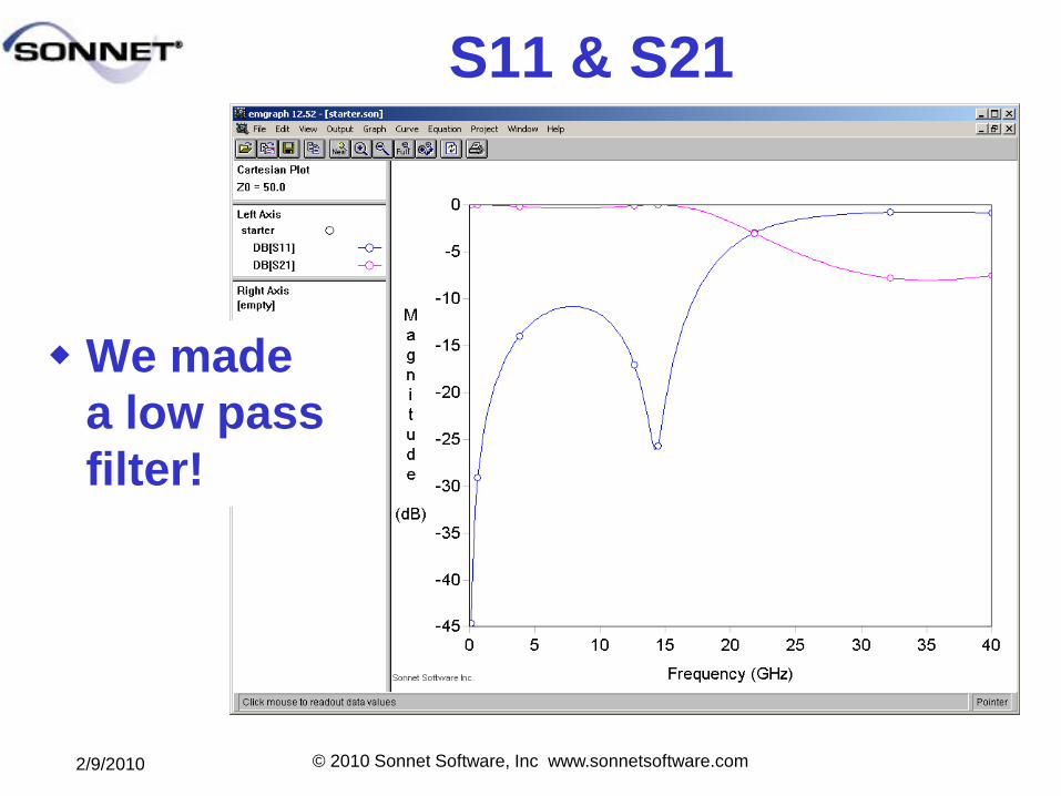
S11 & S21
We made
a low pass
filter!
2/9/2010 © 2010 Sonnet Software, Inc www.sonnetsoftware.com
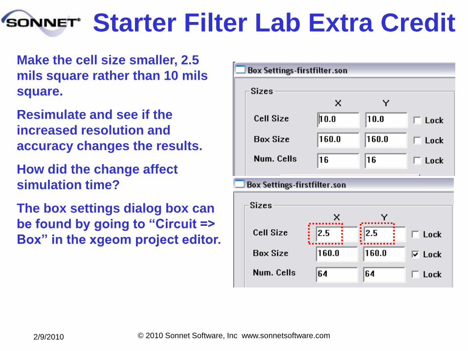
Starter Filter Lab Extra Credit
Make the cell size smaller, 2.5
mils square rather than 10 mils
square.
Resimulate and see if the
increased resolution and
accuracy changes the results.
How did the change affect
simulation time?
The box settings dialog box can
be found by going to ―Circuit =>
Box‖ in the xgeom project editor.
2/9/2010 © 2010 Sonnet Software, Inc www.sonnetsoftware.com
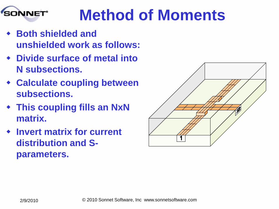
Method of Moments Both shielded and
unshielded work as follows:
Divide surface of metal into
N subsections.
Calculate coupling between
subsections.
This coupling fills an NxN
matrix.
Invert matrix for current
distribution and S-
parameters.
2/9/2010 © 2010 Sonnet Software, Inc www.sonnetsoftware.com
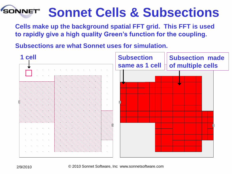
Sonnet Cells & SubsectionsCells make up the background spatial FFT grid. This FFT is used
to rapidly give a high quality Green’s function for the coupling.
Subsections are what Sonnet uses for simulation.
1 cell Subsection
same as 1 cellSubsection made
of multiple cells
2/9/2010 © 2010 Sonnet Software, Inc www.sonnetsoftware.com
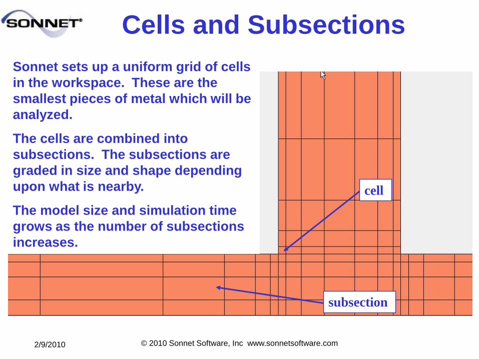
Cells and Subsections
Sonnet sets up a uniform grid of cells
in the workspace. These are the
smallest pieces of metal which will be
analyzed.
The cells are combined into
subsections. The subsections are
graded in size and shape depending
upon what is nearby.
The model size and simulation time
grows as the number of subsections
increases.
cell
subsection
2/9/2010 © 2010 Sonnet Software, Inc www.sonnetsoftware.com
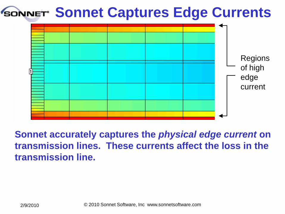
Sonnet Captures Edge Currents
Sonnet accurately captures the physical edge current on
transmission lines. These currents affect the loss in the
transmission line.
Regions
of high
edge
current
2/9/2010 © 2010 Sonnet Software, Inc www.sonnetsoftware.com
Other Features in Sonnet
• Conformal Mesh – for curved transmission lines
• Thick Metal Modeling – using multiple sheets
• Integration with AWR, ADS, and Cadence
Virtuoso
• Co-calibrated ports – calibrated internal ports
• SMD – circuit elements in Sonnet layout
• Remote EM Analysis Job Queuing
• Cluster Computing – with or without LSF
• Multithreading up to 8 cores with high
performance solver
2/9/2010 © 2010 Sonnet Software, Inc www.sonnetsoftware.com
De-embedding Find this entry on de-embedding in the Sonnet User’s Guide
Chapter 7
De-embedding
Each port in a circuit analyzed by em introduces a
discontinuity into the analysis results. In addition, any
transmission lines that might be present introduce phase
shift, and possibly, impedance mismatch and loss.
Depending upon the nature of your analysis, this may or
may not be desirable. De-embedding is the process by
which the port discontinuity and transmission line effects
are removed from the analysis results.
2/9/2010 © 2010 Sonnet Software, Inc www.sonnetsoftware.com
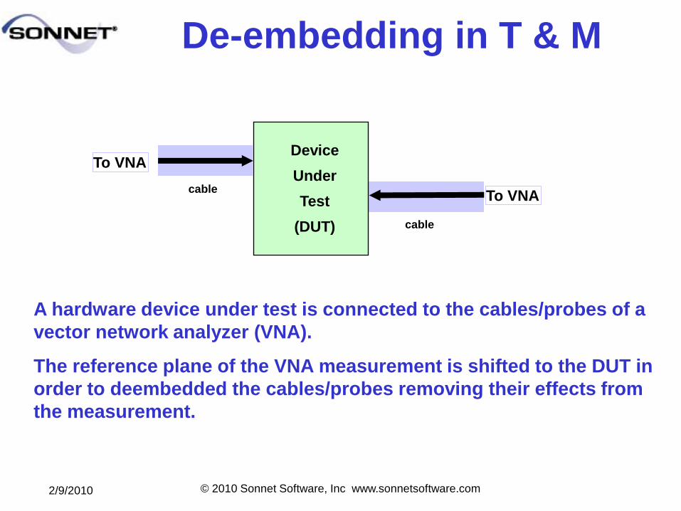
De-embedding in T & M
Device
Under
Test
(DUT) cable
A hardware device under test is connected to the cables/probes of a
vector network analyzer (VNA).
The reference plane of the VNA measurement is shifted to the DUT in
order to deembedded the cables/probes removing their effects from
the measurement.
To VNA
cableTo VNA
2/9/2010 © 2010 Sonnet Software, Inc www.sonnetsoftware.com
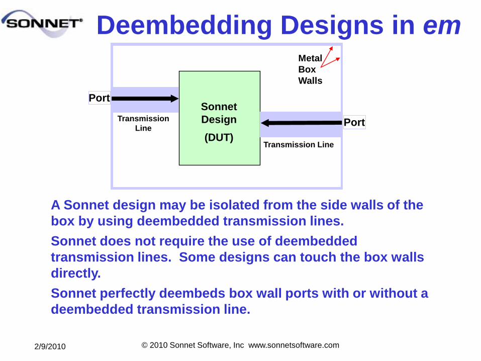
Deembedding Designs in em
Port
Metal
Box
Walls
Sonnet
Design
(DUT)Transmission Line
A Sonnet design may be isolated from the side walls of the
box by using deembedded transmission lines.
Sonnet does not require the use of deembedded
transmission lines. Some designs can touch the box walls
directly.
Sonnet perfectly deembeds box wall ports with or without a
deembedded transmission line.
Port
Transmission
Line
2/9/2010 © 2010 Sonnet Software, Inc www.sonnetsoftware.com
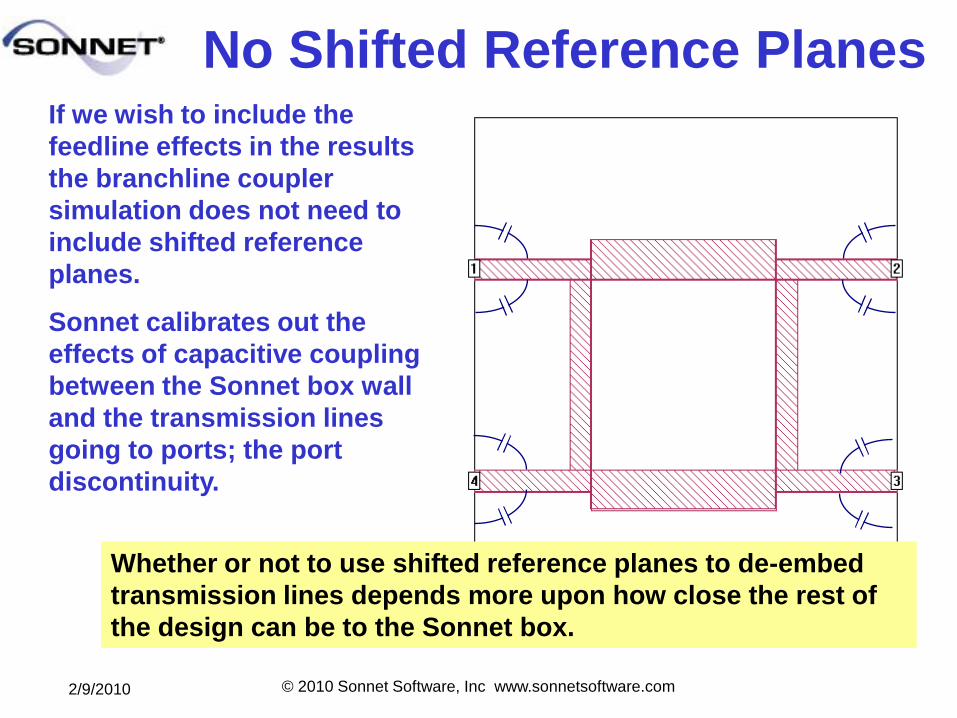
No Shifted Reference PlanesIf we wish to include the
feedline effects in the results
the branchline coupler
simulation does not need to
include shifted reference
planes.
Sonnet calibrates out the
effects of capacitive coupling
between the Sonnet box wall
and the transmission lines
going to ports; the port
discontinuity.
Whether or not to use shifted reference planes to de-embed
transmission lines depends more upon how close the rest of
the design can be to the Sonnet box.
2/9/2010 © 2010 Sonnet Software, Inc www.sonnetsoftware.com
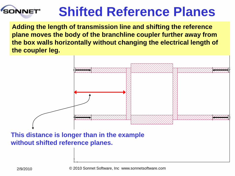
Shifted Reference PlanesAdding the length of transmission line and shifting the reference
plane moves the body of the branchline coupler further away from
the box walls horizontally without changing the electrical length of
the coupler leg.
This distance is longer than in the example
without shifted reference planes.
2/9/2010 © 2010 Sonnet Software, Inc www.sonnetsoftware.com
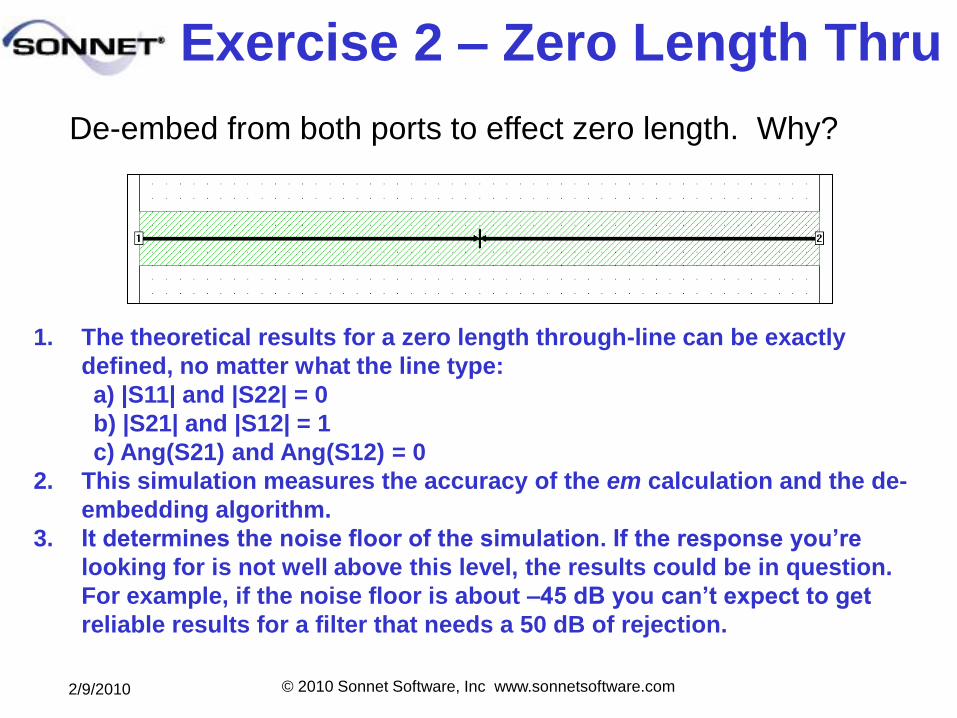
Exercise 2 – Zero Length Thru
1. The theoretical results for a zero length through-line can be exactly
defined, no matter what the line type:
a) |S11| and |S22| = 0
b) |S21| and |S12| = 1
c) Ang(S21) and Ang(S12) = 0
2. This simulation measures the accuracy of the em calculation and the de-
embedding algorithm.
3. It determines the noise floor of the simulation. If the response you’re
looking for is not well above this level, the results could be in question.
For example, if the noise floor is about –45 dB you can’t expect to get
reliable results for a filter that needs a 50 dB of rejection.
De-embed from both ports to effect zero length. Why?

2/9/2010 © 2010 Sonnet Software, Inc www.sonnetsoftware.com
ZLT Simulation Plan Define the working environment
– Box 500 x 160 mils with cells 10 x 5 mils
– Box lossless top and bottom metal
– Symmetry
– Default units of mils and GHz
Define the geometries
– Dielectric layer 50 mils of er = 10.2 loss tan 0.002
– Air dielectric layer of 500 mils above substrate
– Metal for polygons copper: conductivity 5.8 e7, thickness = 1.34, CR = 0
– Rectangle of width “w” (20w50) on layer 0 running from x = 0 to x= 500 centered on symmetry line.
– Ports at both ends with reference planes shifted into the middle so as to touch.
Define the type of analysis to be done
– Analyze from 1 to 10 GHz in one GHz steps
– Linear frequency sweep
Simulate and analyze
2/9/2010 © 2010 Sonnet Software, Inc www.sonnetsoftware.com
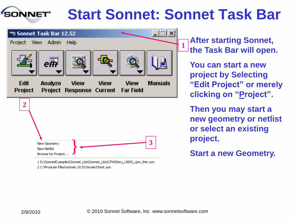
Start Sonnet: Sonnet Task Bar
After starting Sonnet,
the Task Bar will open.
You can start a new
project by Selecting
―Edit Project‖ or merely
clicking on ―Project‖.
Then you may start a
new geometry or netlist
or select an existing
project.
Start a new Geometry.
1
2
3}
2/9/2010 © 2010 Sonnet Software, Inc www.sonnetsoftware.com
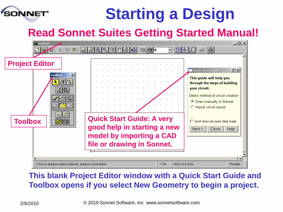
Starting a Design
This blank Project Editor window with a Quick Start Guide and
Toolbox opens if you select New Geometry to begin a project.
Quick Start Guide: A very
good help in starting a new
model by importing a CAD
file or drawing in Sonnet.
Project Editor
Toolbox
Read Sonnet Suites Getting Started Manual!
2/9/2010 © 2010 Sonnet Software, Inc www.sonnetsoftware.com
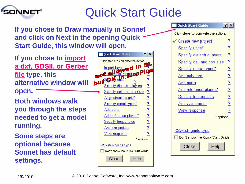
Quick Start Guide
If you chose to Draw manually in Sonnet
and click on Next in the opening Quick
Start Guide, this window will open.
If you chose to import
a dxf, GDSII, or Gerber
file type, this
alternative window will
open.
Both windows walk
you through the steps
needed to get a model
running.
Some steps are
optional because
Sonnet has default
settings.
2/9/2010 © 2010 Sonnet Software, Inc www.sonnetsoftware.com
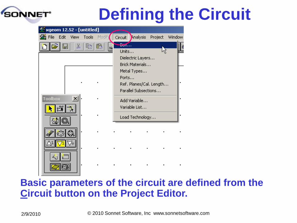
Defining the Circuit
Basic parameters of the circuit are defined from the Circuit button on the Project Editor.
2/9/2010 © 2010 Sonnet Software, Inc www.sonnetsoftware.com
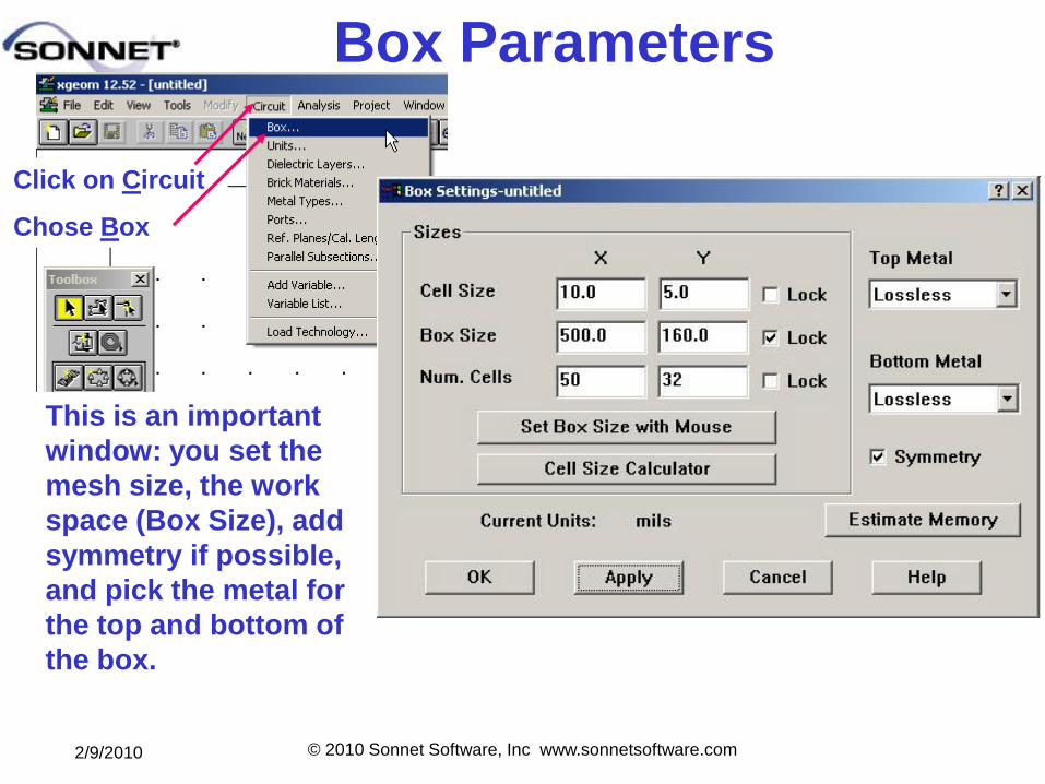
Box Parameters
Click on Circuit
Chose Box
This is an important
window: you set the
mesh size, the work
space (Box Size), add
symmetry if possible,
and pick the metal for
the top and bottom of
the box.
2/9/2010 © 2010 Sonnet Software, Inc www.sonnetsoftware.com
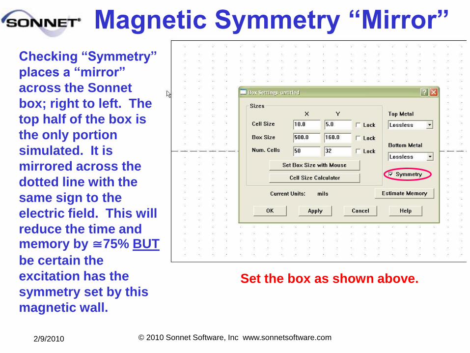
Magnetic Symmetry ―Mirror‖
Checking ―Symmetry‖
places a ―mirror‖
across the Sonnet
box; right to left. The
top half of the box is
the only portion
simulated. It is
mirrored across the
dotted line with the
same sign to the
electric field. This will
reduce the time and memory by 75% BUT
be certain the
excitation has the
symmetry set by this
magnetic wall.
Set the box as shown above.
2/9/2010 © 2010 Sonnet Software, Inc www.sonnetsoftware.com
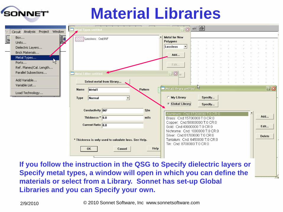
Material Libraries
If you follow the instruction in the QSG to Specify dielectric layers or
Specify metal types, a window will open in which you can define the
materials or select from a Library. Sonnet has set-up Global
Libraries and you can Specify your own.
2/9/2010 © 2010 Sonnet Software, Inc www.sonnetsoftware.com
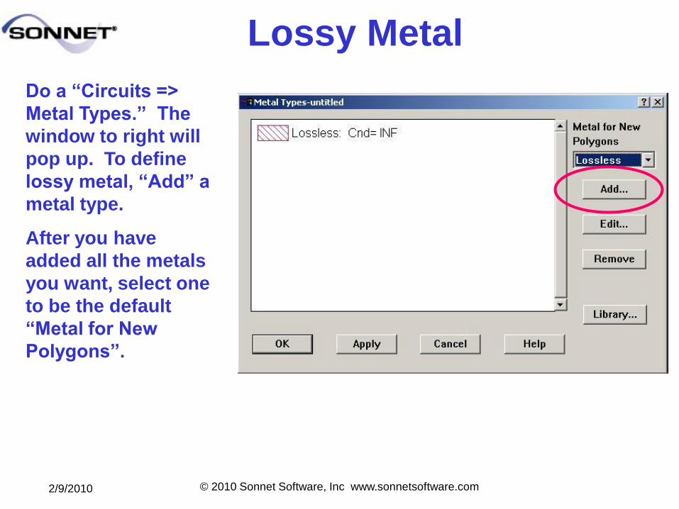
Lossy Metal
Do a ―Circuits =>
Metal Types.‖ The
window to right will
pop up. To define
lossy metal, ―Add‖ a
metal type.
After you have
added all the metals
you want, select one
to be the default
―Metal for New
Polygons‖.
2/9/2010 © 2010 Sonnet Software, Inc www.sonnetsoftware.com
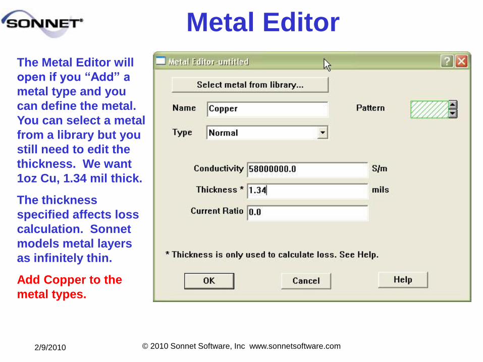
Metal Editor
The Metal Editor will
open if you ―Add‖ a
metal type and you
can define the metal.
You can select a metal
from a library but you
still need to edit the
thickness. We want
1oz Cu, 1.34 mil thick.
The thickness
specified affects loss
calculation. Sonnet
models metal layers
as infinitely thin.
Add Copper to the
metal types.
2/9/2010 © 2010 Sonnet Software, Inc www.sonnetsoftware.com
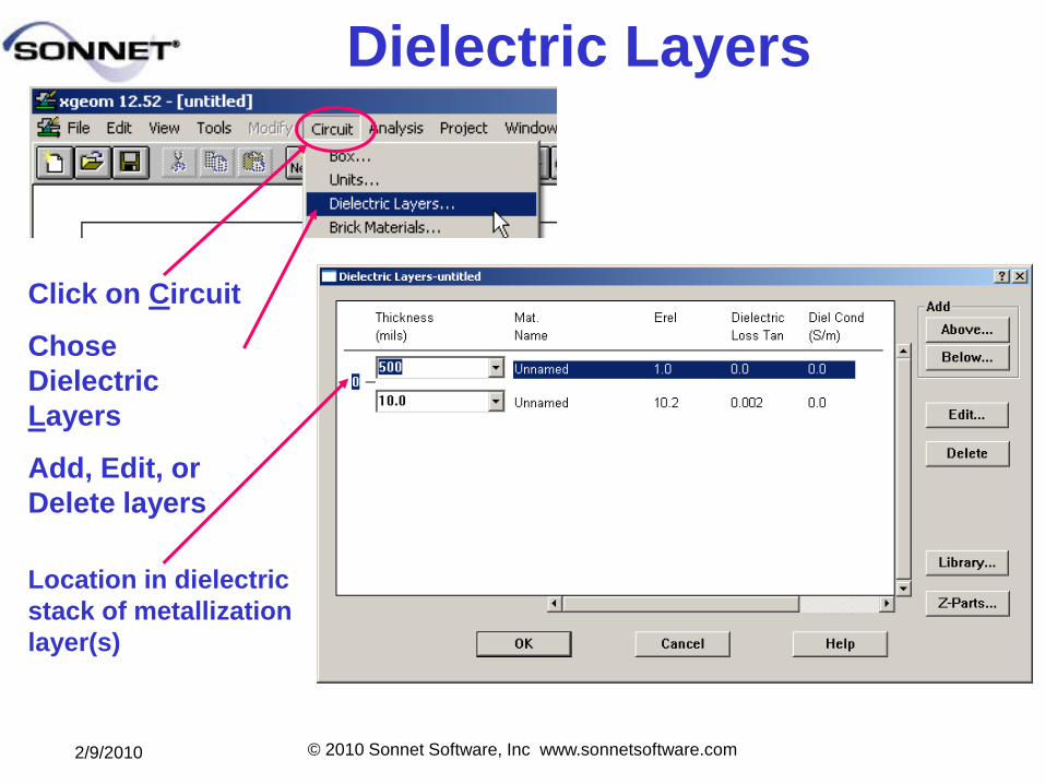
Dielectric Layers
Click on Circuit
Chose
Dielectric
Layers
Add, Edit, or
Delete layers
Location in dielectric
stack of metallization
layer(s)
2/9/2010 © 2010 Sonnet Software, Inc www.sonnetsoftware.com
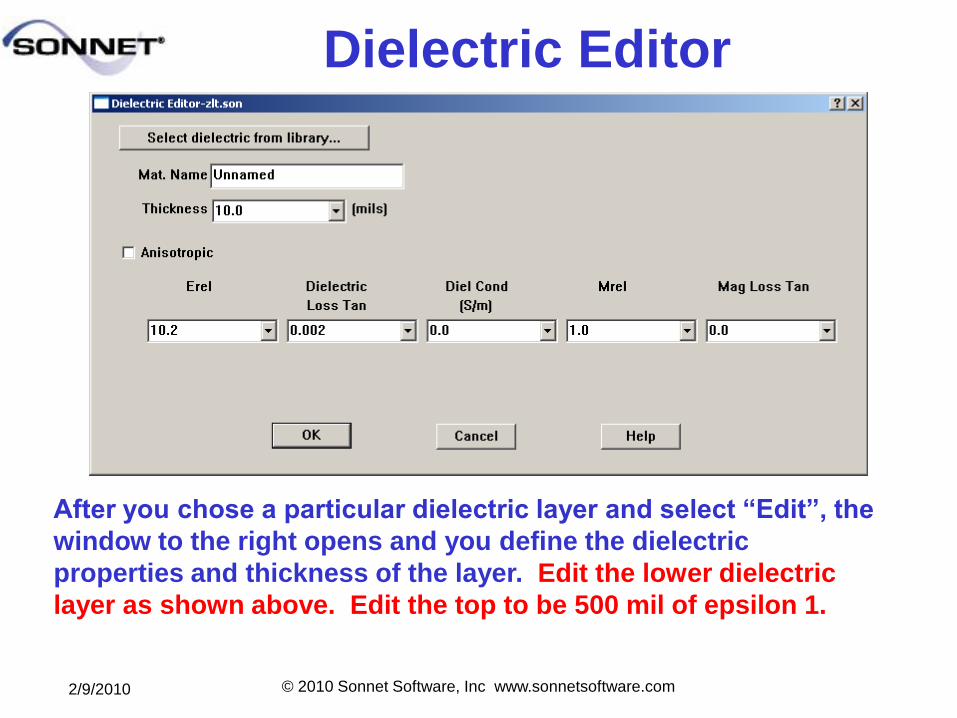
Dielectric Editor
After you chose a particular dielectric layer and select ―Edit‖, the
window to the right opens and you define the dielectric
properties and thickness of the layer. Edit the lower dielectric
layer as shown above. Edit the top to be 500 mil of epsilon 1.
2/9/2010 © 2010 Sonnet Software, Inc www.sonnetsoftware.com
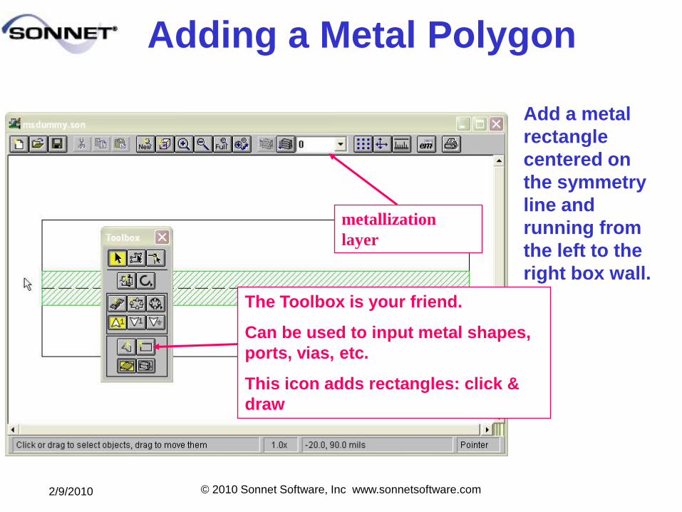
Adding a Metal Polygon
metallization
layer
The Toolbox is your friend.
Can be used to input metal shapes,
ports, vias, etc.
This icon adds rectangles: click &
draw
Add a metal
rectangle
centered on
the symmetry
line and
running from
the left to the
right box wall.
2/9/2010 © 2010 Sonnet Software, Inc www.sonnetsoftware.com
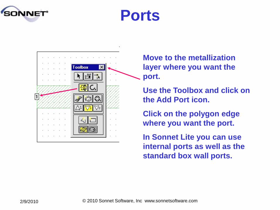
Ports
Move to the metallization
layer where you want the
port.
Use the Toolbox and click on
the Add Port icon.
Click on the polygon edge
where you want the port.
In Sonnet Lite you can use
internal ports as well as the
standard box wall ports.
2/9/2010 © 2010 Sonnet Software, Inc www.sonnetsoftware.com
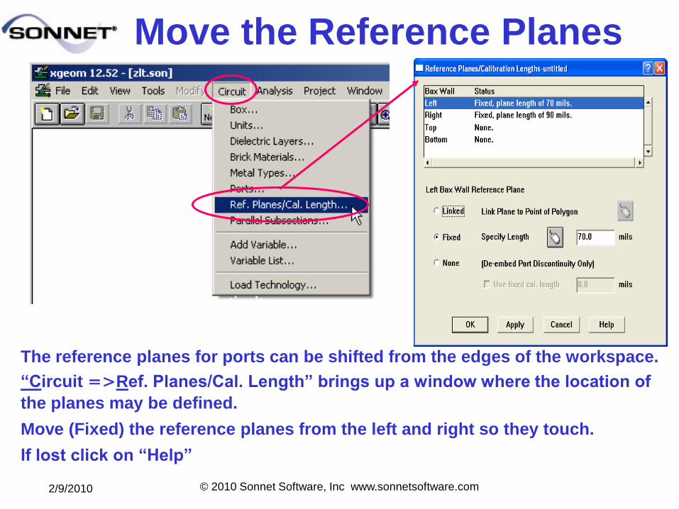
Move the Reference Planes
Modeling a Discontinuity Internal Port Placement
The reference planes for ports can be shifted from the edges of the workspace.
―Circuit Ref. Planes/Cal. Length‖ brings up a window where the location of
the planes may be defined.
Move (Fixed) the reference planes from the left and right so they touch.
If lost click on ―Help‖
2/9/2010 © 2010 Sonnet Software, Inc www.sonnetsoftware.com
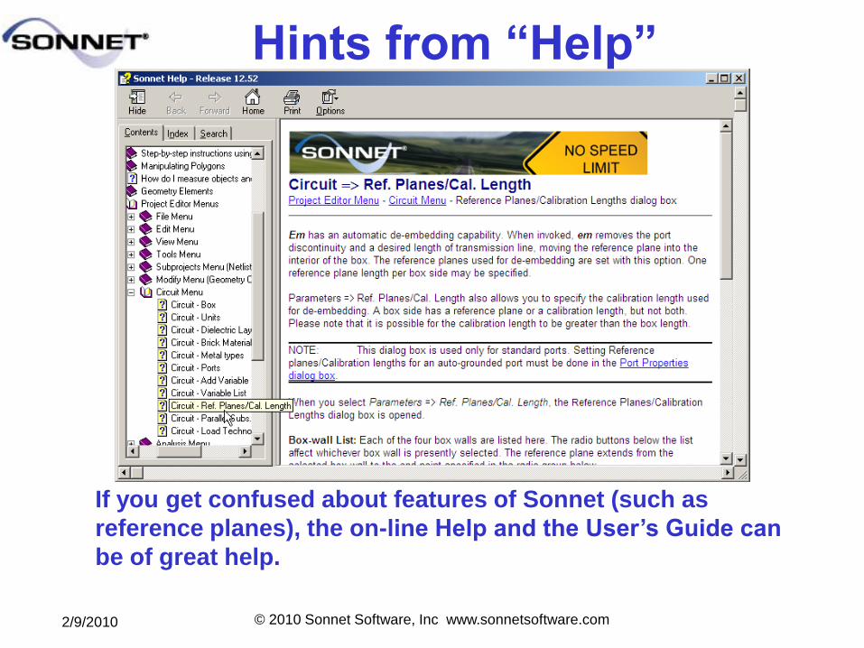
Hints from ―Help‖
If you get confused about features of Sonnet (such as
reference planes), the on-line Help and the User’s Guide can
be of great help.
2/9/2010 © 2010 Sonnet Software, Inc www.sonnetsoftware.com
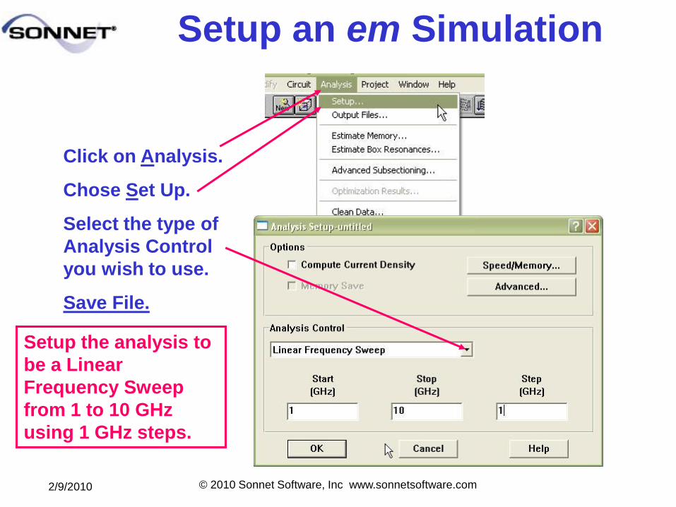
Setup an em Simulation
Click on Analysis.
Chose Set Up.
Select the type of
Analysis Control
you wish to use.
Save File.
Setup the analysis to
be a Linear
Frequency Sweep
from 1 to 10 GHz
using 1 GHz steps.
2/9/2010 © 2010 Sonnet Software, Inc www.sonnetsoftware.com
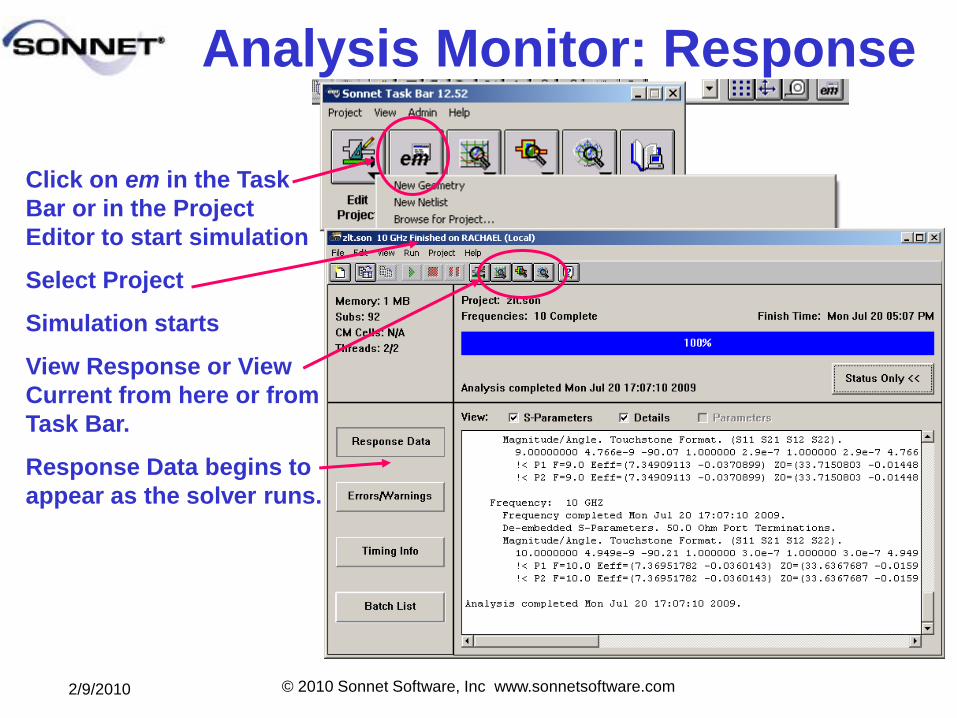
Analysis Monitor: Response
Click on em in the Task
Bar or in the Project
Editor to start simulation
Select Project
Simulation starts
View Response or View
Current from here or from
Task Bar.
Response Data begins to
appear as the solver runs.
2/9/2010 © 2010 Sonnet Software, Inc www.sonnetsoftware.com
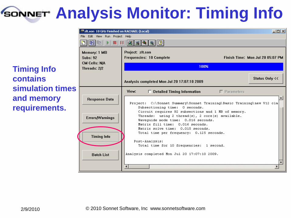
Analysis Monitor: Timing Info
Timing Info
contains
simulation times
and memory
requirements.
2/9/2010 © 2010 Sonnet Software, Inc www.sonnetsoftware.com
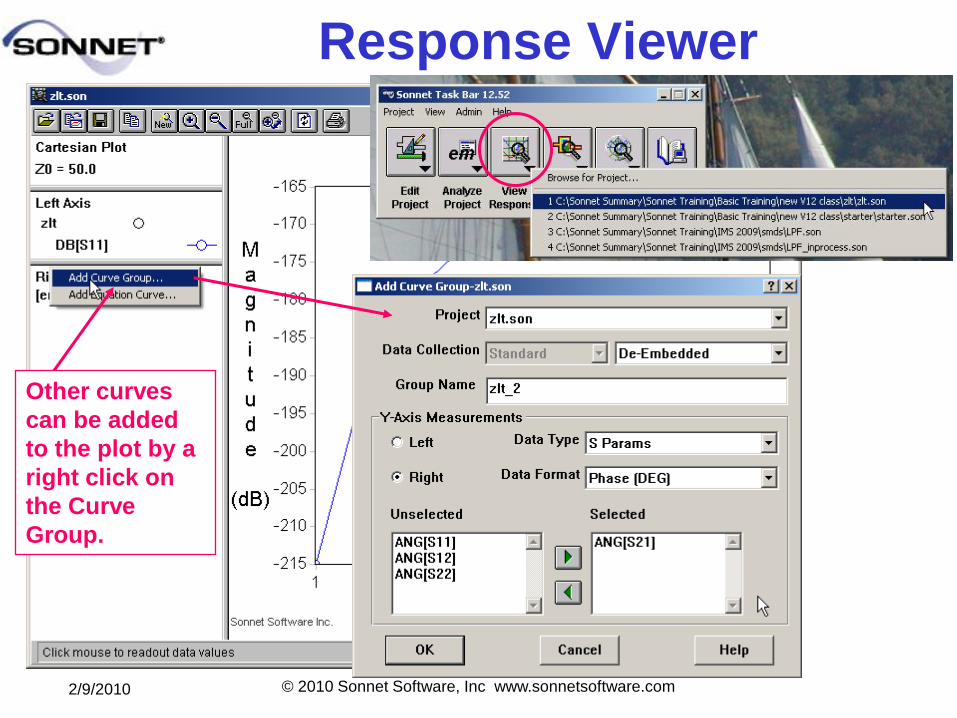
Response Viewer
Other curves
can be added
to the plot by a
right click on
the Curve
Group.
2/9/2010 © 2010 Sonnet Software, Inc www.sonnetsoftware.com
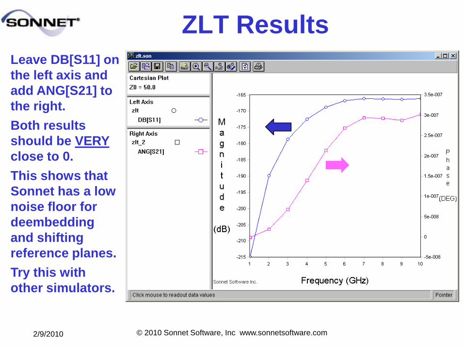
ZLT Results
Leave DB[S11] on
the left axis and
add ANG[S21] to
the right.
Both results
should be VERY
close to 0.
This shows that
Sonnet has a low
noise floor for
deembedding
and shifting
reference planes.
Try this with
other simulators.
2/9/2010 © 2010 Sonnet Software, Inc www.sonnetsoftware.com
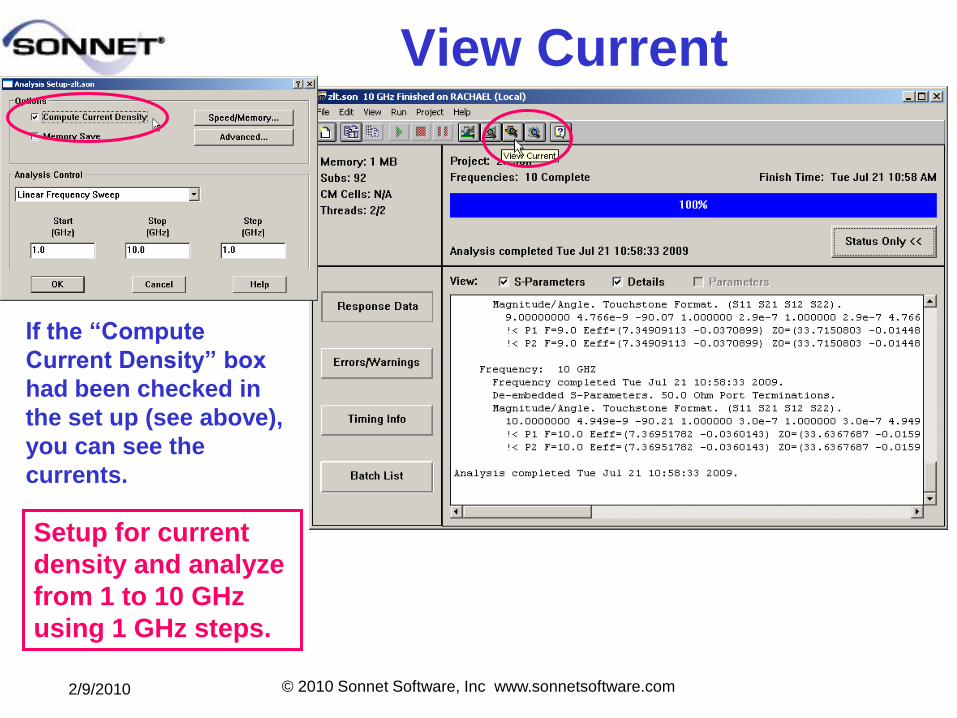
View Current
If the ―Compute
Current Density‖ box
had been checked in
the set up (see above),
you can see the
currents.
Setup for current
density and analyze
from 1 to 10 GHz
using 1 GHz steps.
2/9/2010 © 2010 Sonnet Software, Inc www.sonnetsoftware.com
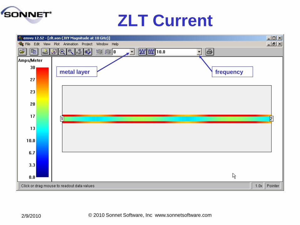
ZLT Current
metal layer frequency
2/9/2010 © 2010 Sonnet Software, Inc www.sonnetsoftware.com
What have we learned?
To build a model in Sonnet:
1. Define your working environment first. This
includes box size, metal types, and dielectric
layers.
2. Use the Toolbox to put metal shapes on the
proper layers and to add vias and ports.
3. Set up the analysis type proper for your
model: ABS, parameter sweep, etc.
4. Check yourself (and your software)
occasionally by doing a simple model for
which you know the results.
2/9/2010 © 2010 Sonnet Software, Inc www.sonnetsoftware.com
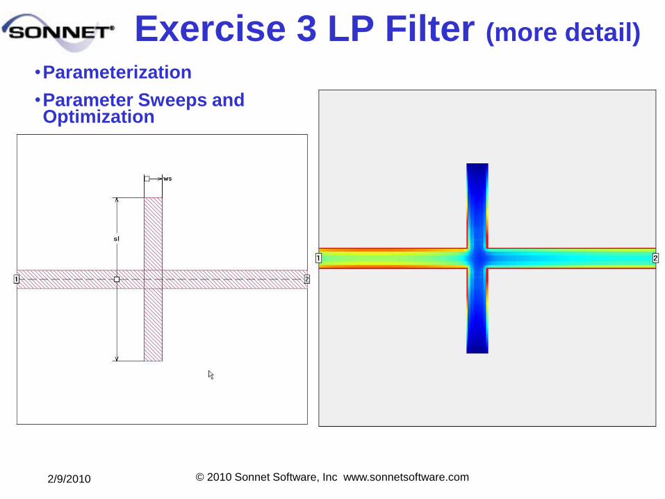
Exercise 3 LP Filter (more detail)
•Parameterization
•Parameter Sweeps and Optimization
2/9/2010 © 2010 Sonnet Software, Inc www.sonnetsoftware.com
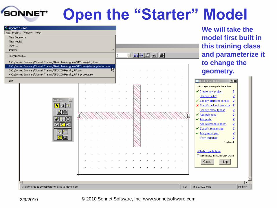
Open the ―Starter‖ ModelWe will take the
model first built in
this training class
and parameterize it
to change the
geometry.
2/9/2010 © 2010 Sonnet Software, Inc www.sonnetsoftware.com
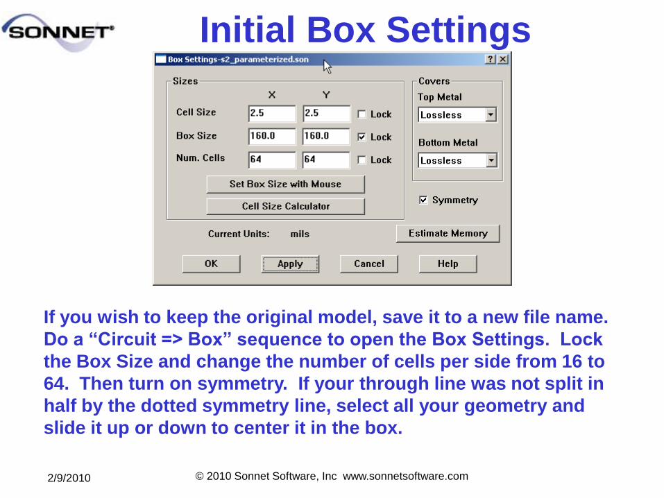
Initial Box Settings
If you wish to keep the original model, save it to a new file name.
Do a ―Circuit => Box‖ sequence to open the Box Settings. Lock
the Box Size and change the number of cells per side from 16 to
64. Then turn on symmetry. If your through line was not split in
half by the dotted symmetry line, select all your geometry and
slide it up or down to center it in the box.
2/9/2010 © 2010 Sonnet Software, Inc www.sonnetsoftware.com
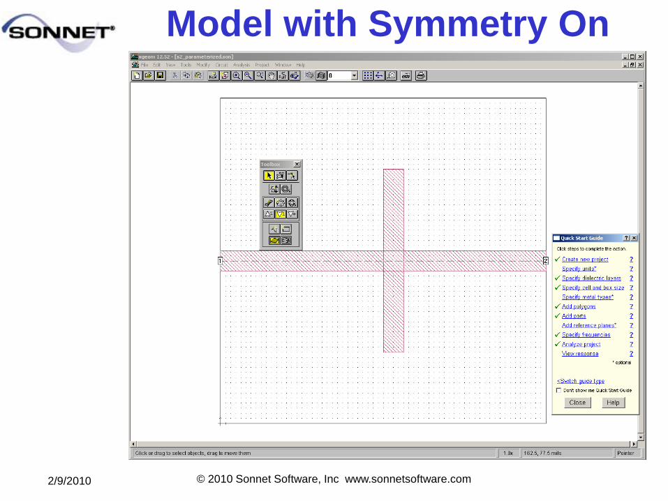
Model with Symmetry On
2/9/2010 © 2010 Sonnet Software, Inc www.sonnetsoftware.com
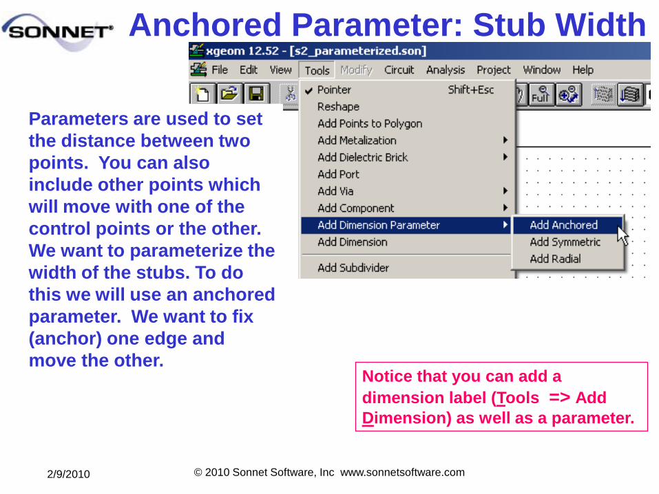
Anchored Parameter: Stub Width
Notice that you can add a
dimension label (Tools => Add
Dimension) as well as a parameter.
Parameters are used to set
the distance between two
points. You can also
include other points which
will move with one of the
control points or the other.
We want to parameterize the
width of the stubs. To do
this we will use an anchored
parameter. We want to fix
(anchor) one edge and
move the other.
2/9/2010 © 2010 Sonnet Software, Inc www.sonnetsoftware.com
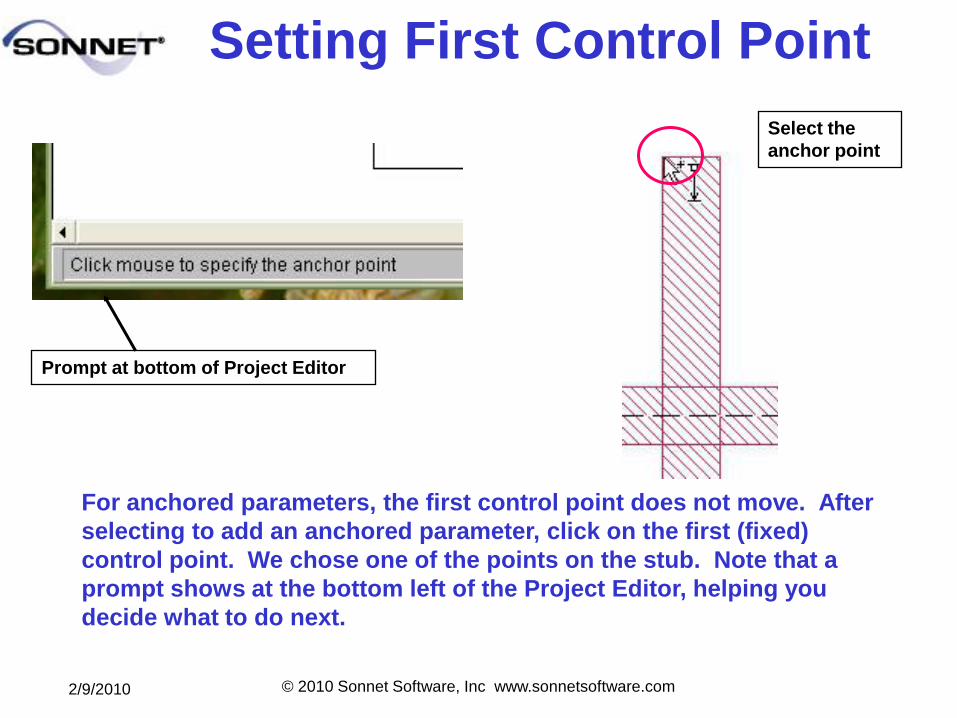
Setting First Control Point
For anchored parameters, the first control point does not move. After
selecting to add an anchored parameter, click on the first (fixed)
control point. We chose one of the points on the stub. Note that a
prompt shows at the bottom left of the Project Editor, helping you
decide what to do next.
Prompt at bottom of Project Editor
Select the
anchor point
2/9/2010 © 2010 Sonnet Software, Inc www.sonnetsoftware.com
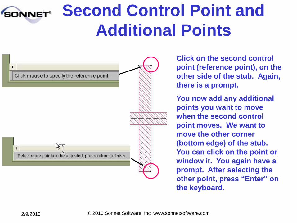
Second Control Point and
Additional Points
Click on the second control
point (reference point), on the
other side of the stub. Again,
there is a prompt.
You now add any additional
points you want to move
when the second control
point moves. We want to
move the other corner
(bottom edge) of the stub.
You can click on the point or
window it. You again have a
prompt. After selecting the
other point, press ―Enter‖ on
the keyboard.
2/9/2010 © 2010 Sonnet Software, Inc www.sonnetsoftware.com
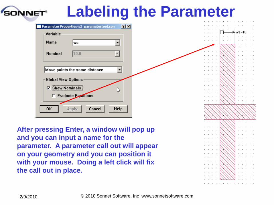
Labeling the Parameter
After pressing Enter, a window will pop up
and you can input a name for the
parameter. A parameter call out will appear
on your geometry and you can position it
with your mouse. Doing a left click will fix
the call out in place.
2/9/2010 © 2010 Sonnet Software, Inc www.sonnetsoftware.com
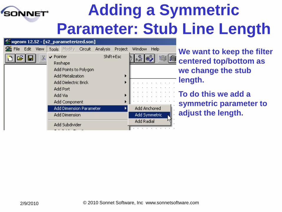
Adding a Symmetric
Parameter: Stub Line Length
We want to keep the filter
centered top/bottom as
we change the stub
length.
To do this we add a
symmetric parameter to
adjust the length.
2/9/2010 © 2010 Sonnet Software, Inc www.sonnetsoftware.com
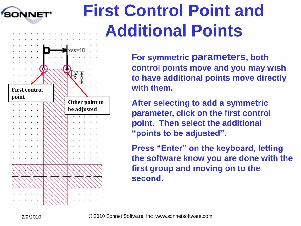
First Control Point and
Additional Points
For symmetric parameters, both
control points move and you may wish
to have additional points move directly
with them.
After selecting to add a symmetric
parameter, click on the first control
point. Then select the additional
―points to be adjusted‖.
Press ―Enter‖ on the keyboard, letting
the software know you are done with the
first group and moving on to the
second.
First control
pointOther point to
be adjusted
2/9/2010 © 2010 Sonnet Software, Inc www.sonnetsoftware.com
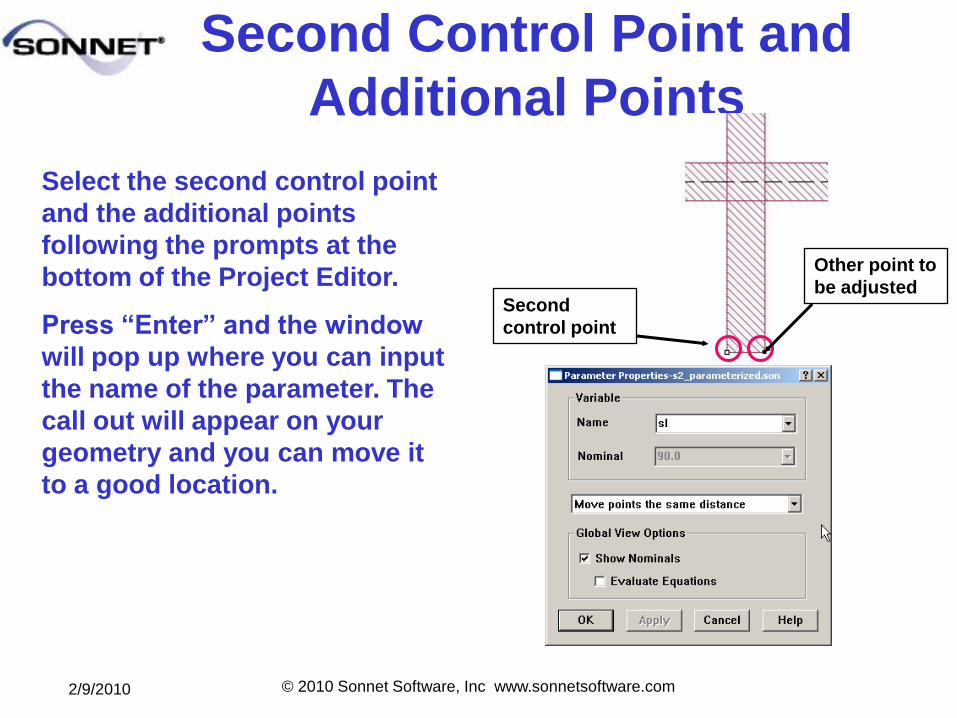
Second Control Point and
Additional Points
Select the second control point
and the additional points
following the prompts at the
bottom of the Project Editor.
Press ―Enter‖ and the window
will pop up where you can input
the name of the parameter. The
call out will appear on your
geometry and you can move it
to a good location.
Second
control point
Other point to
be adjusted
2/9/2010 © 2010 Sonnet Software, Inc www.sonnetsoftware.com
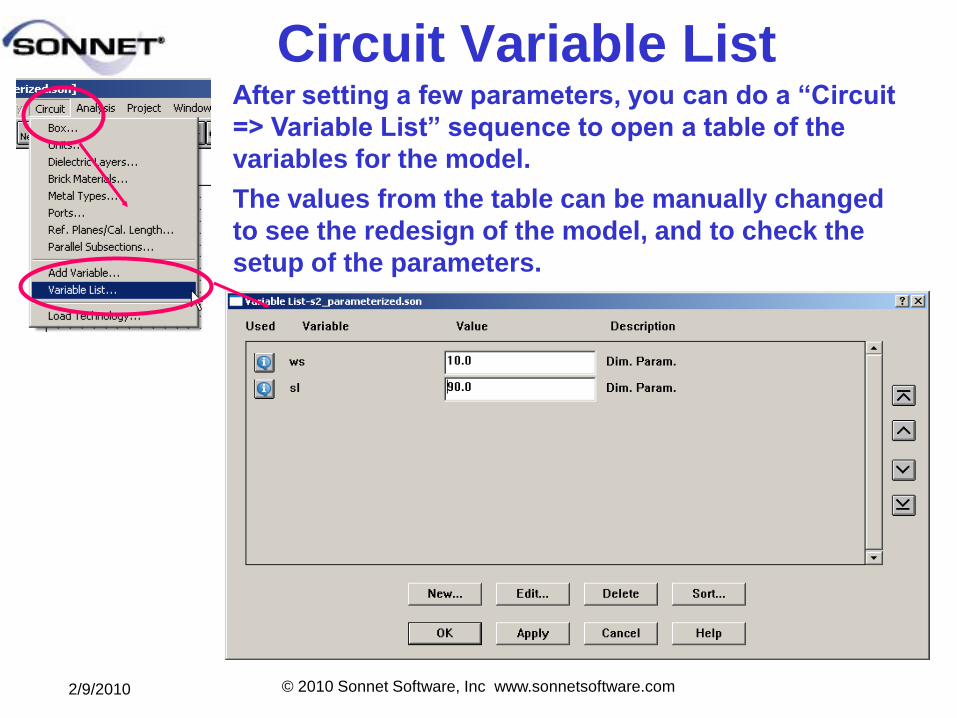
Circuit Variable ListAfter setting a few parameters, you can do a ―Circuit
=> Variable List‖ sequence to open a table of the
variables for the model.
The values from the table can be manually changed
to see the redesign of the model, and to check the
setup of the parameters.
2/9/2010 © 2010 Sonnet Software, Inc www.sonnetsoftware.com
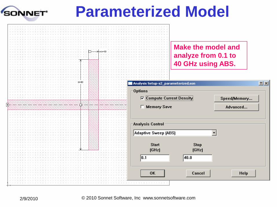
Parameterized Model
Make the model and
analyze from 0.1 to
40 GHz using ABS.
2/9/2010 © 2010 Sonnet Software, Inc www.sonnetsoftware.com
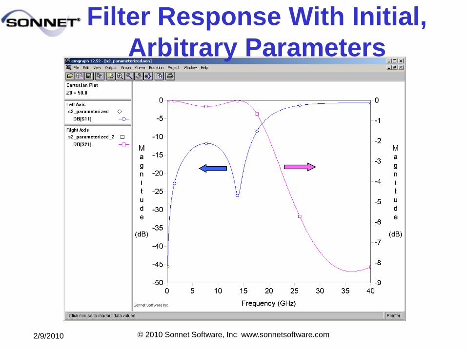
Filter Response With Initial,
Arbitrary Parameters
2/9/2010 © 2010 Sonnet Software, Inc www.sonnetsoftware.com
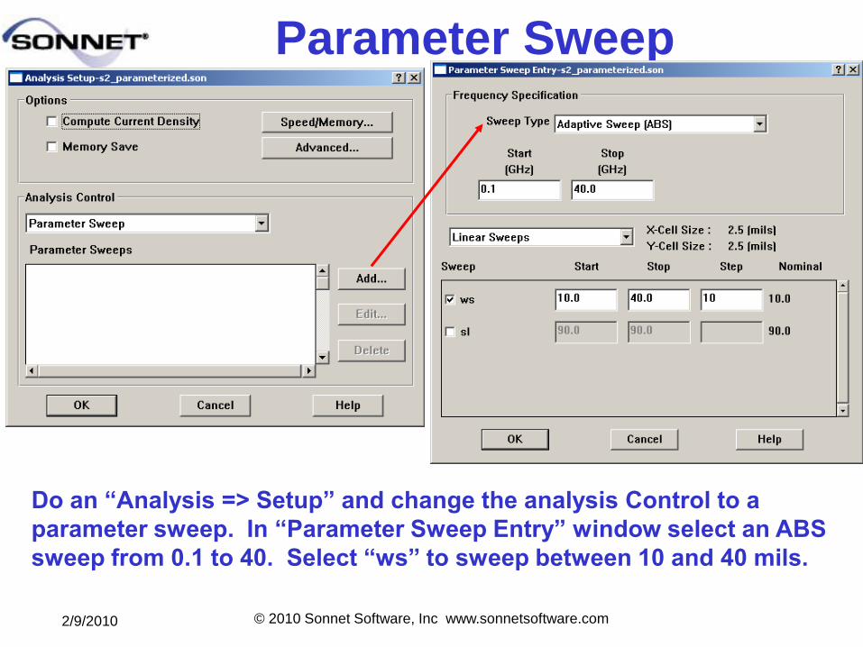
Parameter Sweep
Do an ―Analysis => Setup‖ and change the analysis Control to a
parameter sweep. In ―Parameter Sweep Entry‖ window select an ABS
sweep from 0.1 to 40. Select ―ws‖ to sweep between 10 and 40 mils.
2/9/2010 © 2010 Sonnet Software, Inc www.sonnetsoftware.com
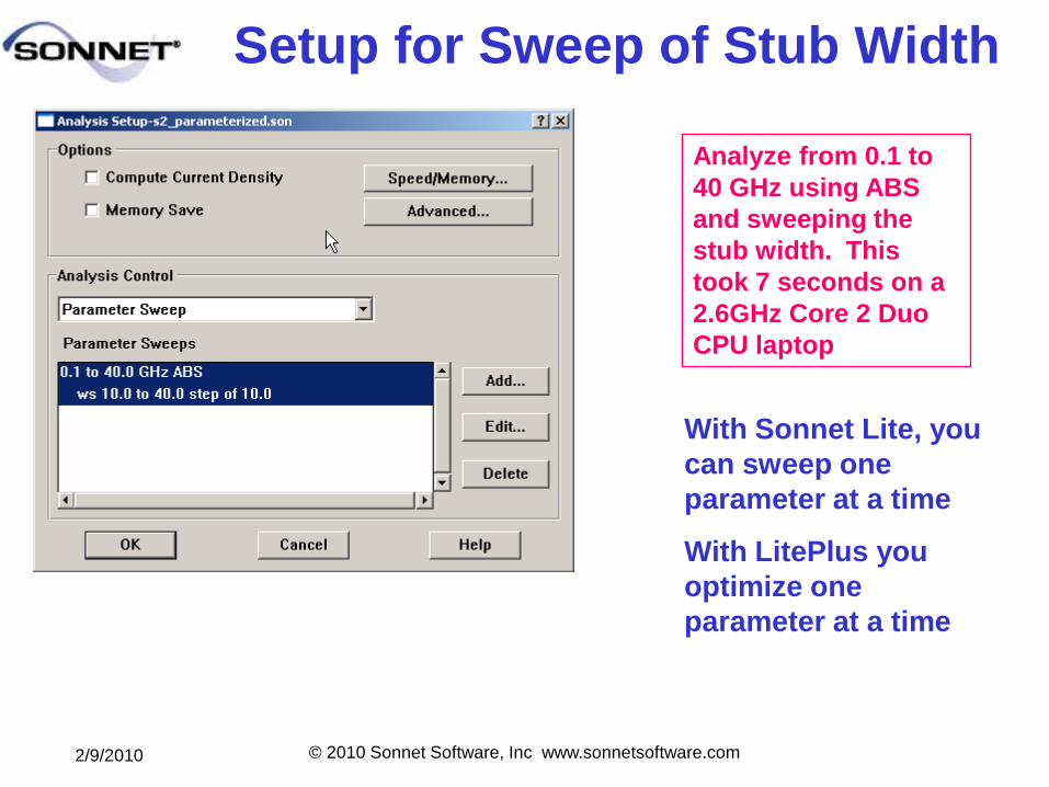
Setup for Sweep of Stub Width
Analyze from 0.1 to
40 GHz using ABS
and sweeping the
stub width. This
took 7 seconds on a
2.6GHz Core 2 Duo
CPU laptop
With Sonnet Lite, you
can sweep one
parameter at a time
With LitePlus you
optimize one
parameter at a time
2/9/2010 © 2010 Sonnet Software, Inc www.sonnetsoftware.com
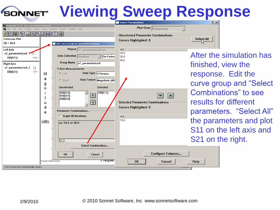
Viewing Sweep Response
After the simulation has
finished, view the
response. Edit the
curve group and “Select
Combinations” to see
results for different
parameters. “Select All”
the parameters and plot
S11 on the left axis and
S21 on the right.
2/9/2010 © 2010 Sonnet Software, Inc www.sonnetsoftware.com
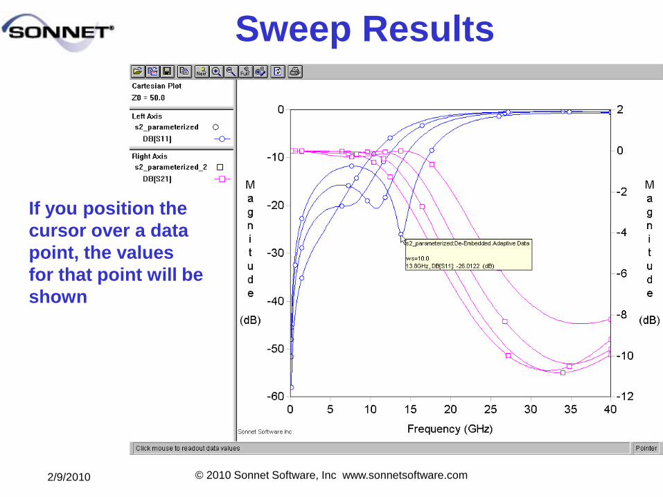
Sweep Results
If you position the
cursor over a data
point, the values
for that point will be
shown
2/9/2010 © 2010 Sonnet Software, Inc www.sonnetsoftware.com
What have we learned?
To help build geometries in Sonnet:
1. Build the correct topology in an “easy” form first.
Then parameterize the model and adjust the
parameters to give the correct geometry.
2. Parameterize your models out from one point to
avoid circular definitions.
3. Use both anchored and symmetry parameters to
get the correct “growth” of your models.
4. First adjust your parameters using engineering
knowledge then use parameter sweeps and
optimization to find the final design.
2/9/2010 © 2010 Sonnet Software, Inc www.sonnetsoftware.com
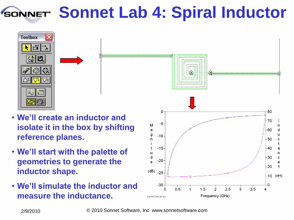
Sonnet Lab 4: Spiral Inductor
• We’ll create an inductor and
isolate it in the box by shifting
reference planes.
• We’ll start with the palette of
geometries to generate the
inductor shape.
• We’ll simulate the inductor and
measure the inductance.
2/9/2010 © 2010 Sonnet Software, Inc www.sonnetsoftware.com
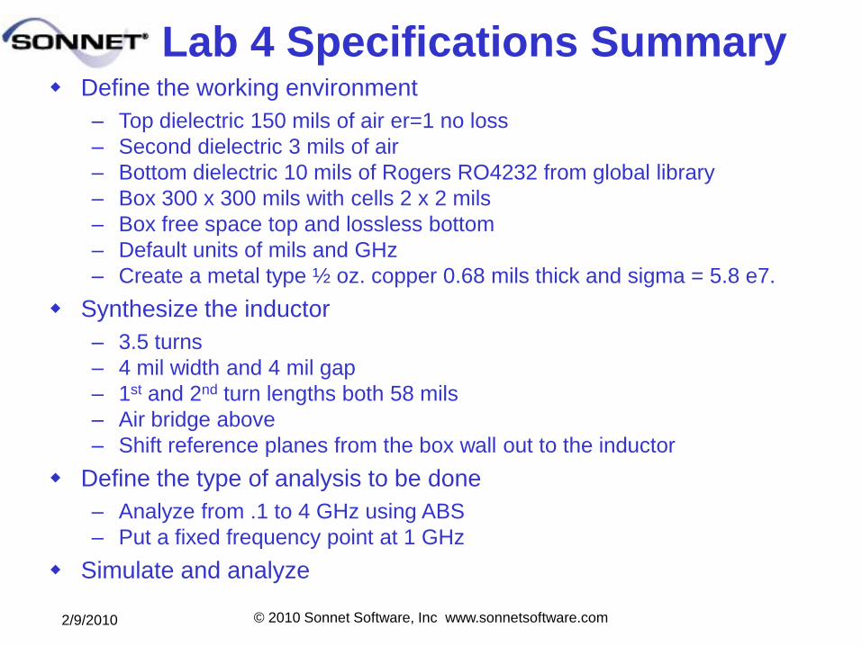
Lab 4 Specifications Summary Define the working environment
– Top dielectric 150 mils of air er=1 no loss
– Second dielectric 3 mils of air
– Bottom dielectric 10 mils of Rogers RO4232 from global library
– Box 300 x 300 mils with cells 2 x 2 mils
– Box free space top and lossless bottom
– Default units of mils and GHz
– Create a metal type ½ oz. copper 0.68 mils thick and sigma = 5.8 e7.
Synthesize the inductor
– 3.5 turns
– 4 mil width and 4 mil gap
– 1st and 2nd turn lengths both 58 mils
– Air bridge above
– Shift reference planes from the box wall out to the inductor
Define the type of analysis to be done
– Analyze from .1 to 4 GHz using ABS
– Put a fixed frequency point at 1 GHz
Simulate and analyze
2/9/2010 © 2010 Sonnet Software, Inc www.sonnetsoftware.com
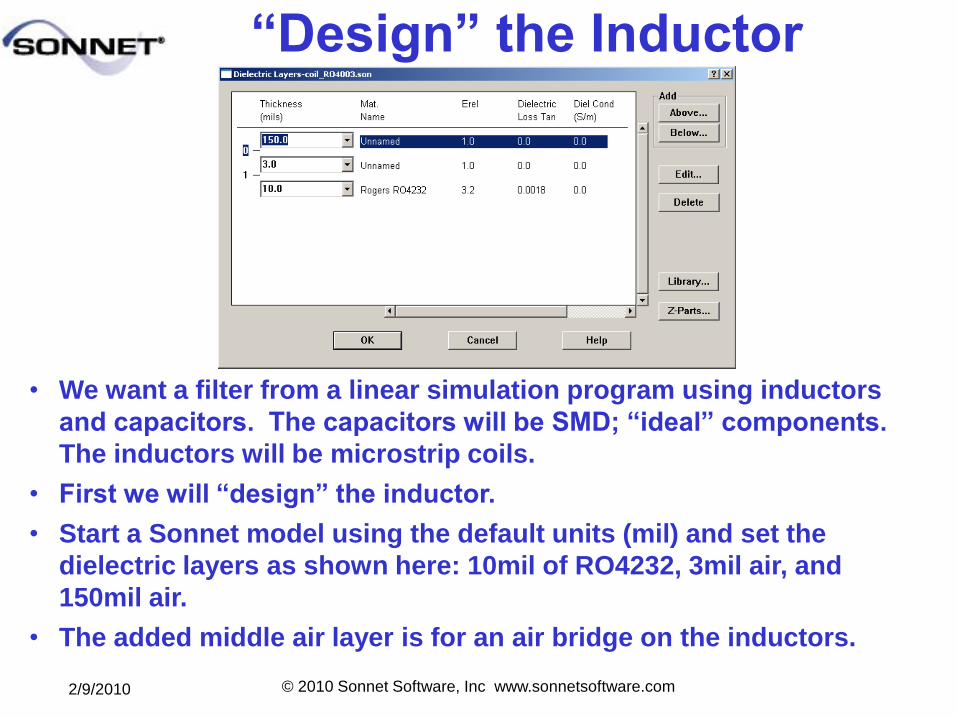
―Design‖ the Inductor
• We want a filter from a linear simulation program using inductors
and capacitors. The capacitors will be SMD; ―ideal‖ components.
The inductors will be microstrip coils.
• First we will ―design‖ the inductor.
• Start a Sonnet model using the default units (mil) and set the
dielectric layers as shown here: 10mil of RO4232, 3mil air, and
150mil air.
• The added middle air layer is for an air bridge on the inductors.
2/9/2010 © 2010 Sonnet Software, Inc www.sonnetsoftware.com
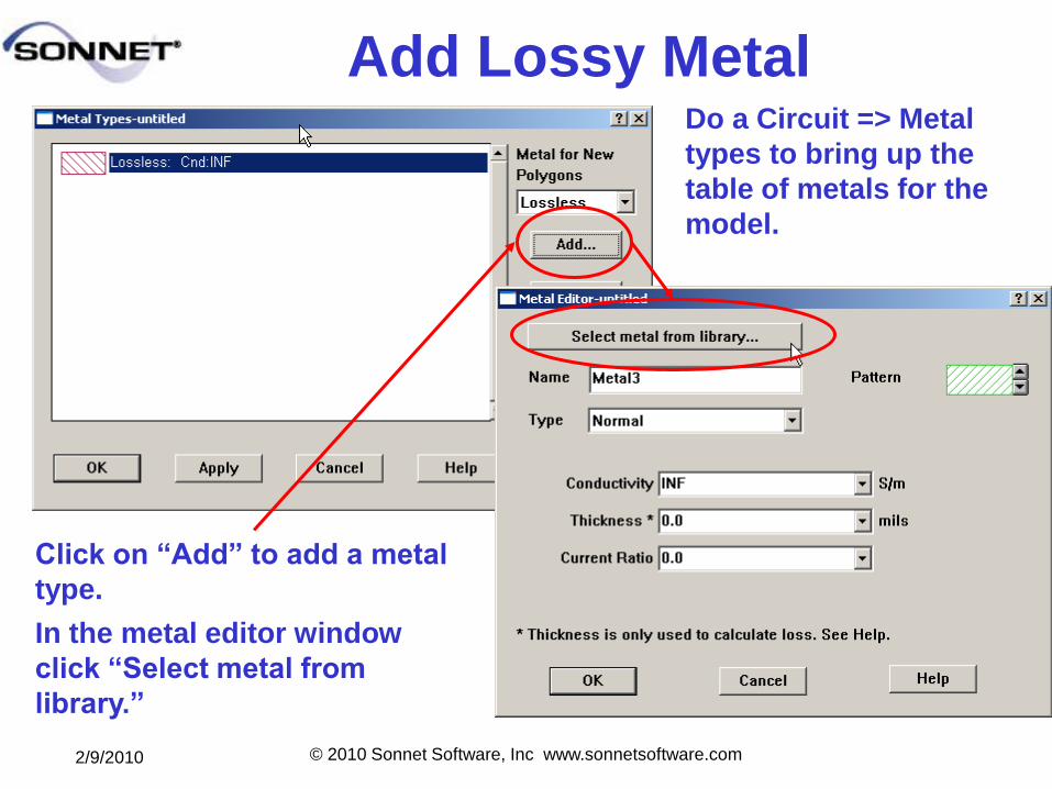
Add Lossy MetalDo a Circuit => Metal
types to bring up the
table of metals for the
model.
Click on ―Add‖ to add a metal
type.
In the metal editor window
click ―Select metal from
library.‖
2/9/2010 © 2010 Sonnet Software, Inc www.sonnetsoftware.com
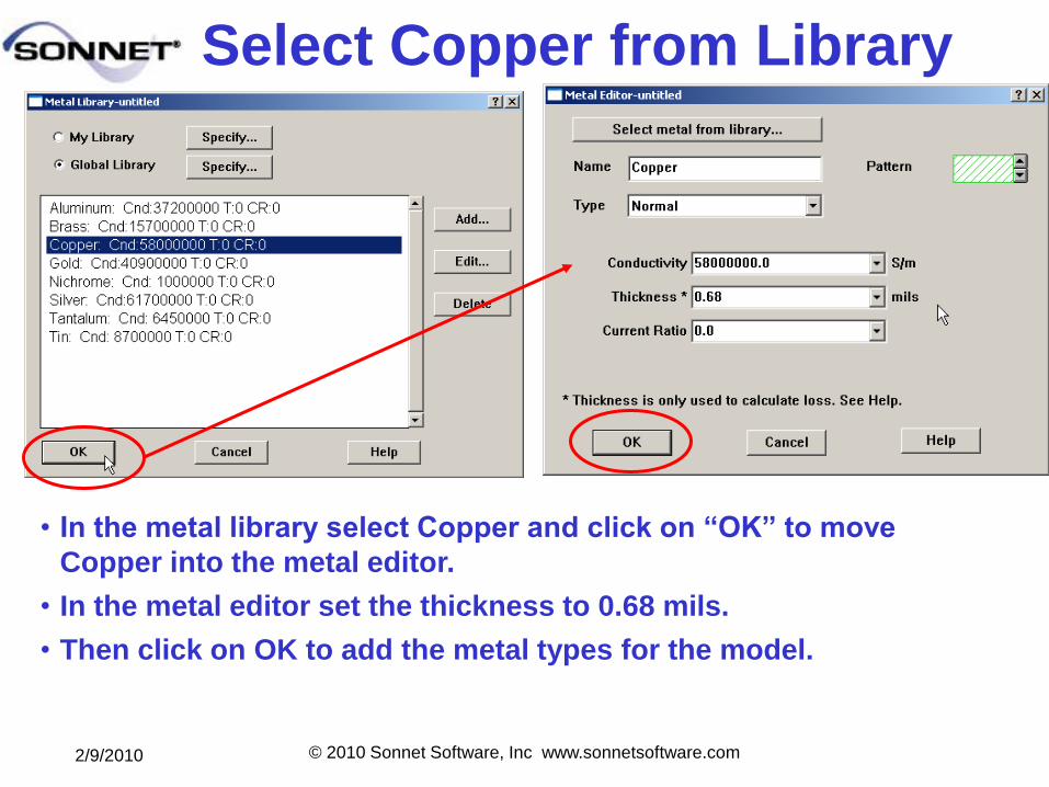
Select Copper from Library
• In the metal library select Copper and click on ―OK‖ to move
Copper into the metal editor.
• In the metal editor set the thickness to 0.68 mils.
• Then click on OK to add the metal types for the model.
2/9/2010 © 2010 Sonnet Software, Inc www.sonnetsoftware.com
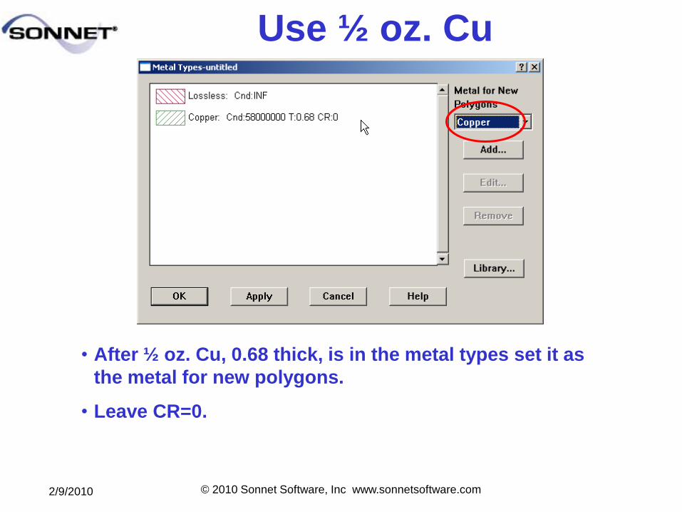
Use ½ oz. Cu
• After ½ oz. Cu, 0.68 thick, is in the metal types set it as
the metal for new polygons.
• Leave CR=0.
2/9/2010 © 2010 Sonnet Software, Inc www.sonnetsoftware.com
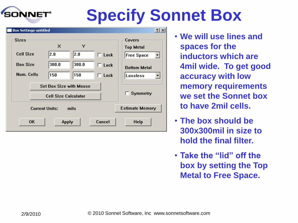
Specify Sonnet Box• We will use lines and
spaces for the
inductors which are
4mil wide. To get good
accuracy with low
memory requirements
we set the Sonnet box
to have 2mil cells.
• The box should be
300x300mil in size to
hold the final filter.
• Take the ―lid‖ off the
box by setting the Top
Metal to Free Space.
2/9/2010 © 2010 Sonnet Software, Inc www.sonnetsoftware.com
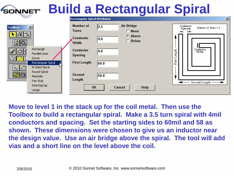
Build a Rectangular Spiral
Move to level 1 in the stack up for the coil metal. Then use the
Toolbox to build a rectangular spiral. Make a 3.5 turn spiral with 4mil
conductors and spacing. Set the starting sides to 60mil and 58 as
shown. These dimensions were chosen to give us an inductor near
the design value. Use an air bridge above the spiral. The tool will add
vias and a short line on the level above the coil.
2/9/2010 © 2010 Sonnet Software, Inc www.sonnetsoftware.com
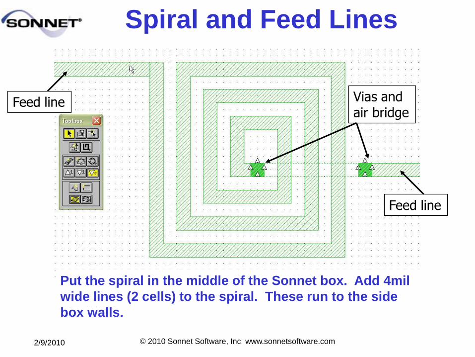
Spiral and Feed Lines
Put the spiral in the middle of the Sonnet box. Add 4mil
wide lines (2 cells) to the spiral. These run to the side
box walls.
Feed line Vias and air bridge
Feed line
2/9/2010 © 2010 Sonnet Software, Inc www.sonnetsoftware.com
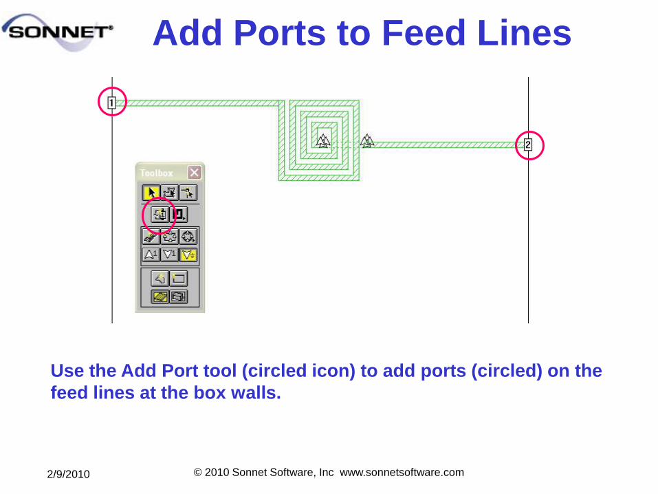
Add Ports to Feed Lines
Use the Add Port tool (circled icon) to add ports (circled) on the
feed lines at the box walls.
2/9/2010 © 2010 Sonnet Software, Inc www.sonnetsoftware.com
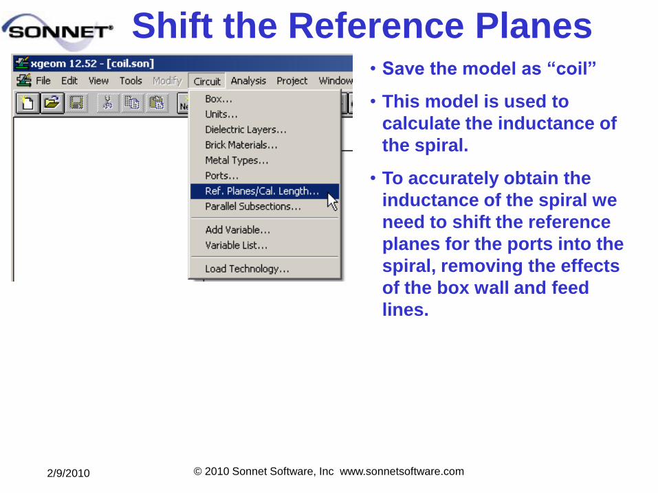
Shift the Reference Planes • Save the model as ―coil‖
• This model is used to
calculate the inductance of
the spiral.
• To accurately obtain the
inductance of the spiral we
need to shift the reference
planes for the ports into the
spiral, removing the effects
of the box wall and feed
lines.
2/9/2010 © 2010 Sonnet Software, Inc www.sonnetsoftware.com
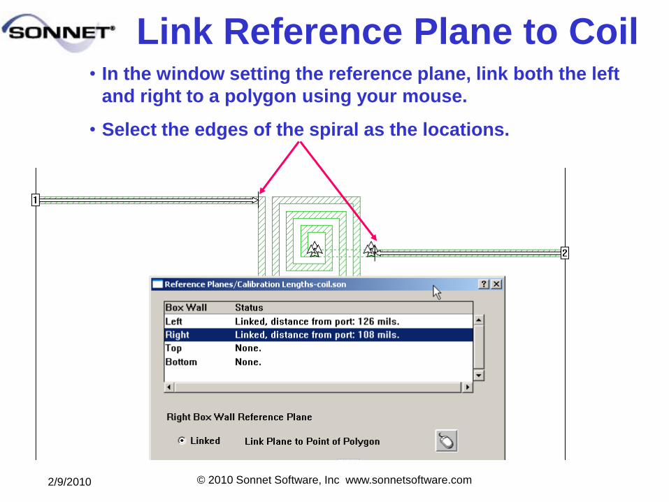
Link Reference Plane to Coil• In the window setting the reference plane, link both the left
and right to a polygon using your mouse.
• Select the edges of the spiral as the locations.
2/9/2010 © 2010 Sonnet Software, Inc www.sonnetsoftware.com
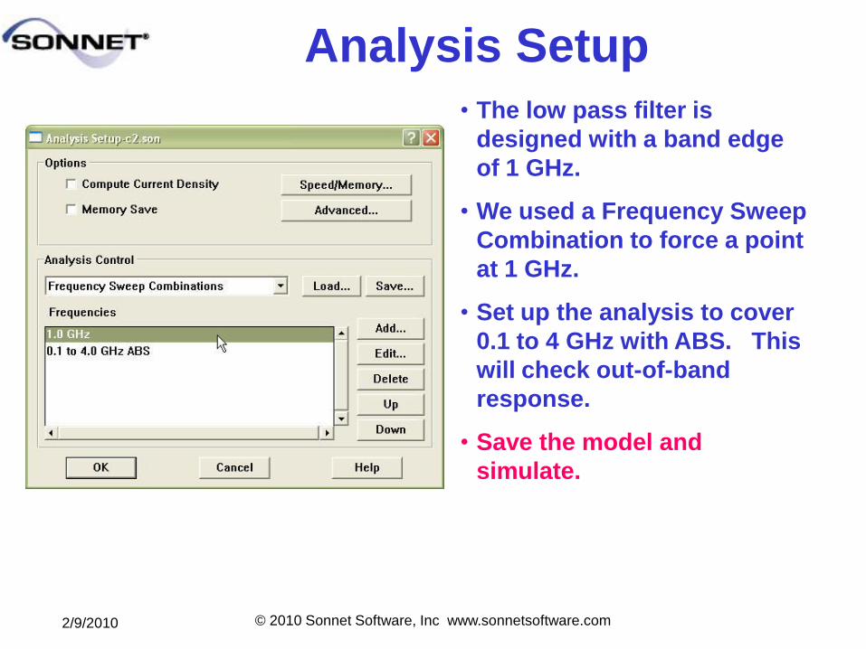
Analysis Setup
• The low pass filter is
designed with a band edge
of 1 GHz.
• We used a Frequency Sweep
Combination to force a point
at 1 GHz.
• Set up the analysis to cover
0.1 to 4 GHz with ABS. This
will check out-of-band
response.
• Save the model and
simulate.
2/9/2010 © 2010 Sonnet Software, Inc www.sonnetsoftware.com
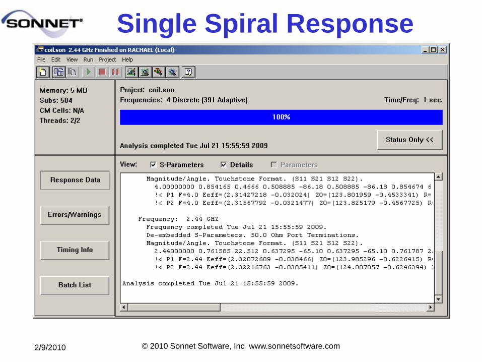
Single Spiral Response
2/9/2010 © 2010 Sonnet Software, Inc www.sonnetsoftware.com
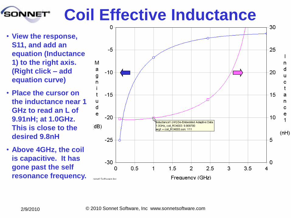
Coil Effective Inductance• View the response,
S11, and add an
equation (Inductance
1) to the right axis.
(Right click – add
equation curve)
• Place the cursor on
the inductance near 1
GHz to read an L of
9.91nH; at 1.0GHz.
This is close to the
desired 9.8nH
• Above 4GHz, the coil
is capacitive. It has
gone past the self
resonance frequency.
2/9/2010 © 2010 Sonnet Software, Inc www.sonnetsoftware.com
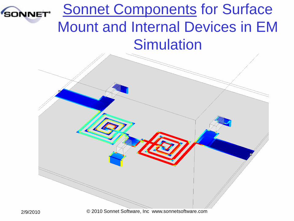
Sonnet Components for Surface
Mount and Internal Devices in EM
Simulation
2/9/2010 © 2010 Sonnet Software, Inc www.sonnetsoftware.com
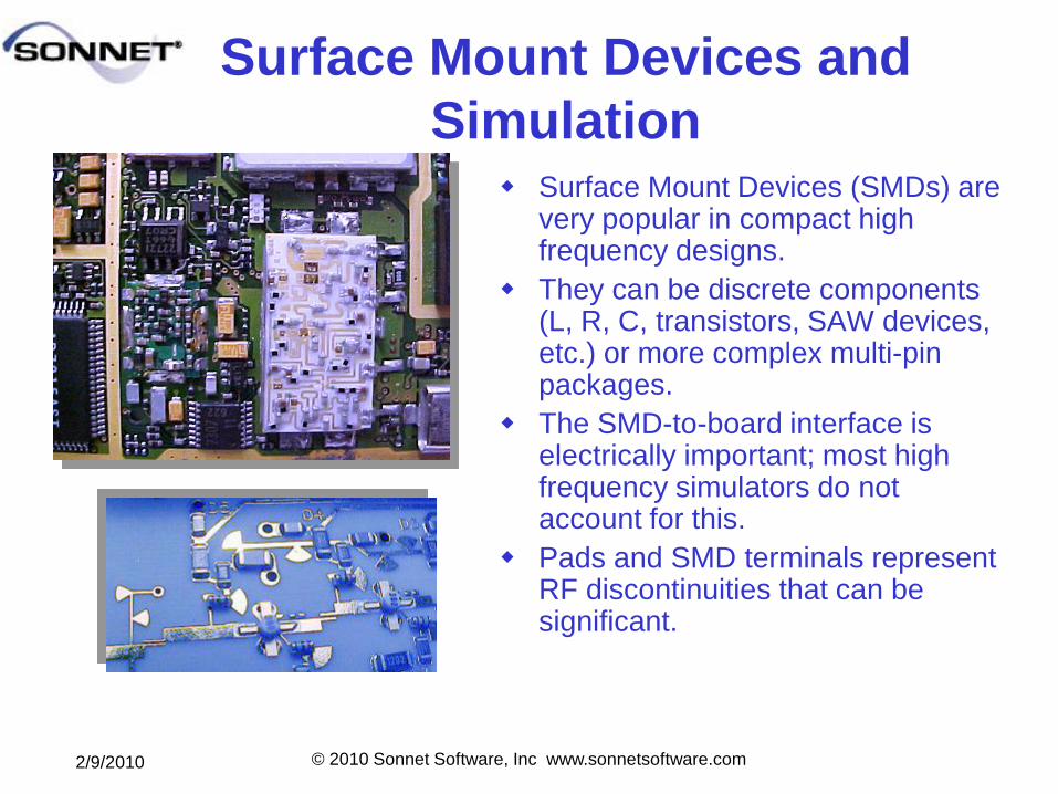
Surface Mount Devices and
Simulation Surface Mount Devices (SMDs) are
very popular in compact high frequency designs.
They can be discrete components (L, R, C, transistors, SAW devices, etc.) or more complex multi-pin packages.
The SMD-to-board interface is electrically important; most high frequency simulators do not account for this.
Pads and SMD terminals represent RF discontinuities that can be significant.
2/9/2010 © 2010 Sonnet Software, Inc www.sonnetsoftware.com
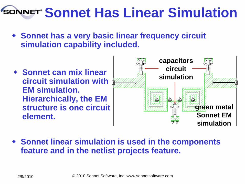
Sonnet has a very basic linear frequency circuit simulation capability included.
Sonnet linear simulation is used in the components feature and in the netlist projects feature.
Sonnet Has Linear Simulation
Sonnet can mix linear circuit simulation with EM simulation. Hierarchically, the EM structure is one circuit element.
green metal
Sonnet EM
simulation
capacitors
circuit
simulation
2/9/2010 © 2010 Sonnet Software, Inc www.sonnetsoftware.com
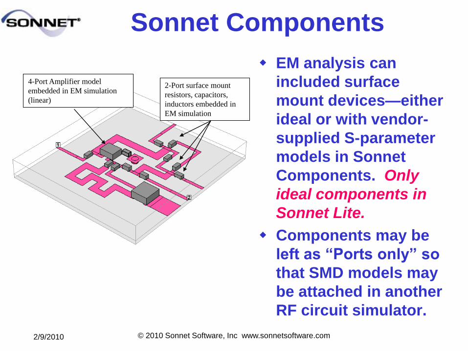
Sonnet Components
EM analysis can
included surface
mount devices—either
ideal or with vendor-
supplied S-parameter
models in Sonnet
Components. Only
ideal components in
Sonnet Lite.
Components may be
left as ―Ports only‖ so
that SMD models may
be attached in another
RF circuit simulator.
4-Port Amplifier model
embedded in EM simulation
(linear)
2-Port surface mount
resistors, capacitors,
inductors embedded in
EM simulation
2/9/2010 © 2010 Sonnet Software, Inc www.sonnetsoftware.com
Internal Components
Sonnet Components can represent Surface Mount Devices, elements buried in a dielectric stackup or ideal lumped elements
Combines both EM and netlist simulation
Component model automatically included by Sonnet netlist, or in your favorite framework (ADS, MWO, Cadence, etc.)
S-parameter SMD models (such as provided by SMD vendors) may be used
Provides an accurate way to account for parasitics associated with surface mount pads and device terminal discontinuities
Utilizes Sonnet’s General Local Ground (GLG) technology with automatic Co-Calibrated™ (CC) Ports – New in Sonnet Suites Release 11
2/9/2010 © 2010 Sonnet Software, Inc www.sonnetsoftware.com
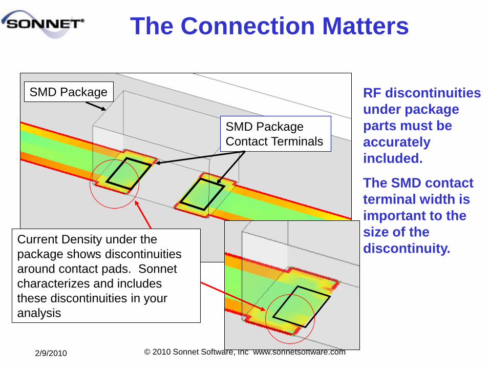
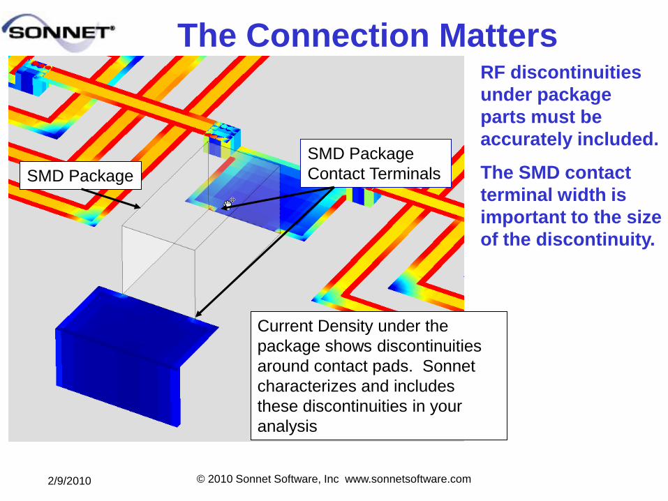
The Connection Matters
SMD Package
Contact Terminals
SMD Package
Current Density under the
package shows discontinuities
around contact pads. Sonnet
characterizes and includes
these discontinuities in your
analysis
RF discontinuities
under package
parts must be
accurately
included.
The SMD contact
terminal width is
important to the
size of the
discontinuity.
2/9/2010 © 2010 Sonnet Software, Inc www.sonnetsoftware.com
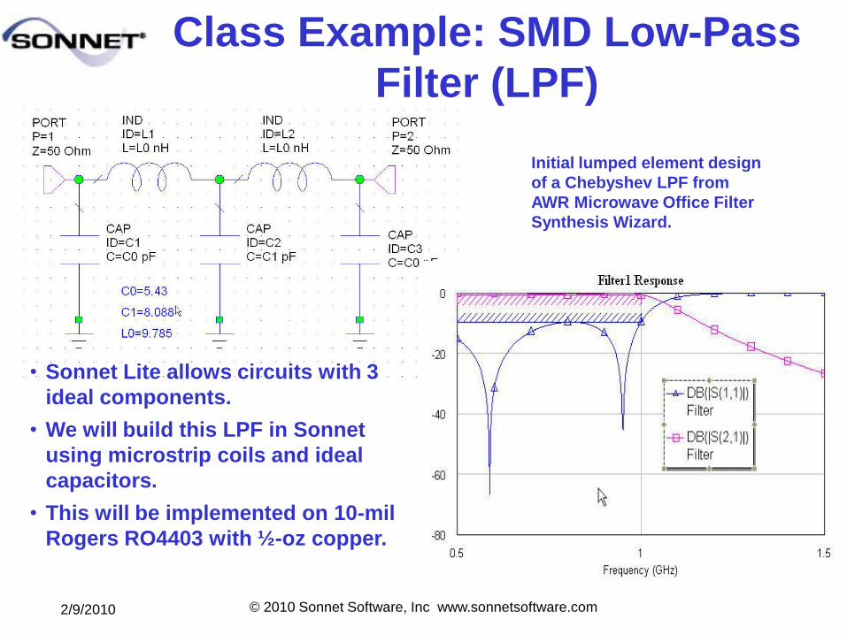
Class Example: SMD Low-Pass
Filter (LPF)
• Sonnet Lite allows circuits with 3
ideal components.
• We will build this LPF in Sonnet
using microstrip coils and ideal
capacitors.
• This will be implemented on 10-mil
Rogers RO4403 with ½-oz copper.
Initial lumped element design
of a Chebyshev LPF from
AWR Microwave Office Filter
Synthesis Wizard.
2/9/2010 © 2010 Sonnet Software, Inc www.sonnetsoftware.com
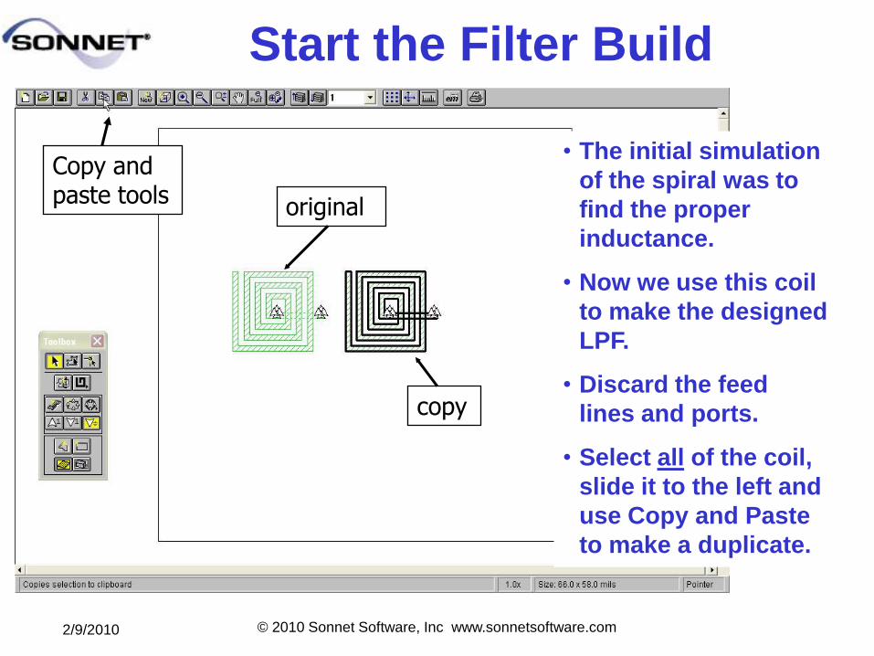
Start the Filter Build
• The initial simulation
of the spiral was to
find the proper
inductance.
• Now we use this coil
to make the designed
LPF.
• Discard the feed
lines and ports.
• Select all of the coil,
slide it to the left and
use Copy and Paste
to make a duplicate.
Copy and paste tools
original
copy
2/9/2010 © 2010 Sonnet Software, Inc www.sonnetsoftware.com
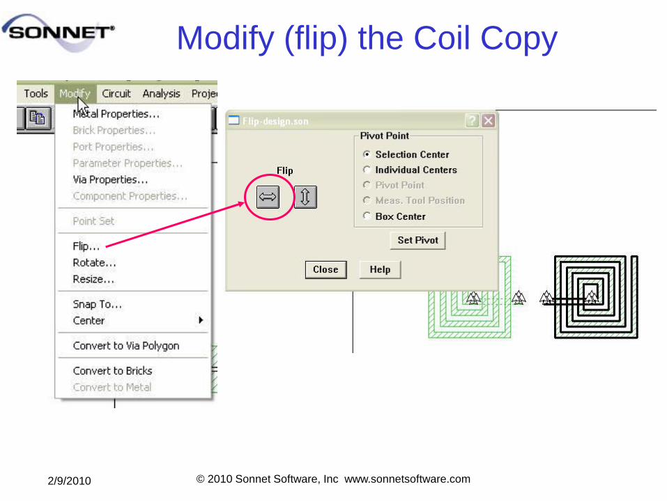
Modify (flip) the Coil Copy
2/9/2010 © 2010 Sonnet Software, Inc www.sonnetsoftware.com
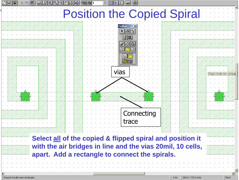
Position the Copied Spiral
Select all of the copied & flipped spiral and position it
with the air bridges in line and the vias 20mil, 10 cells,
apart. Add a rectangle to connect the spirals.
vias
Connecting trace
2/9/2010 © 2010 Sonnet Software, Inc www.sonnetsoftware.com
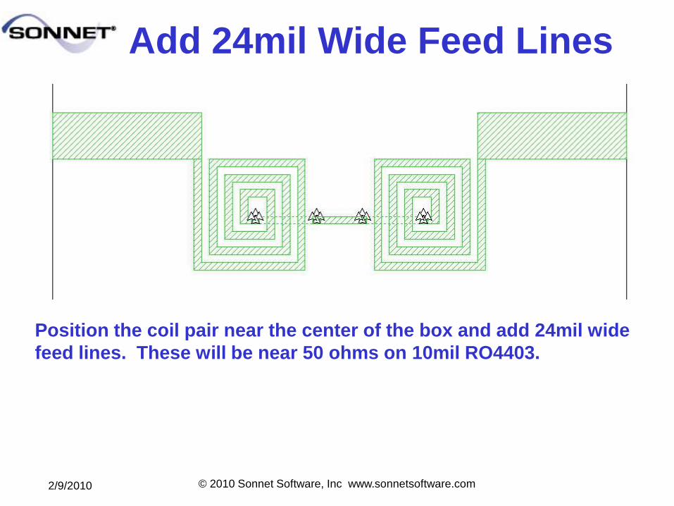
Add 24mil Wide Feed Lines
Position the coil pair near the center of the box and add 24mil wide
feed lines. These will be near 50 ohms on 10mil RO4403.
2/9/2010 © 2010 Sonnet Software, Inc www.sonnetsoftware.com
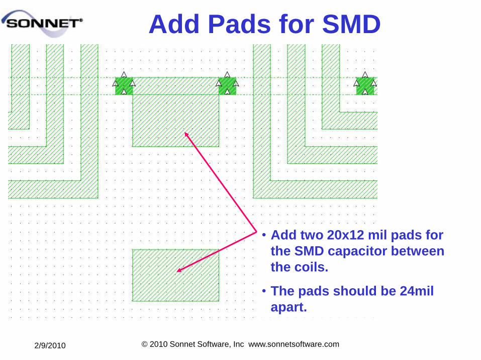
Add Pads for SMD
• Add two 20x12 mil pads for
the SMD capacitor between
the coils.
• The pads should be 24mil
apart.
2/9/2010 © 2010 Sonnet Software, Inc www.sonnetsoftware.com
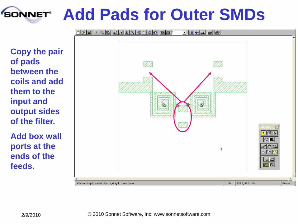
Add Pads for Outer SMDs
Copy the pair
of pads
between the
coils and add
them to the
input and
output sides
of the filter.
Add box wall
ports at the
ends of the
feeds.
2/9/2010 © 2010 Sonnet Software, Inc www.sonnetsoftware.com
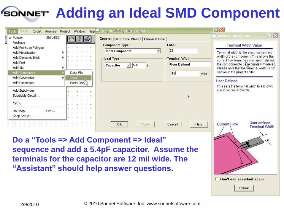
Adding an Ideal SMD Component
Do a ―Tools => Add Component => Ideal‖
sequence and add a 5.4pF capacitor. Assume the
terminals for the capacitor are 12 mil wide. The
―Assistant‖ should help answer questions.
2/9/2010 © 2010 Sonnet Software, Inc www.sonnetsoftware.com
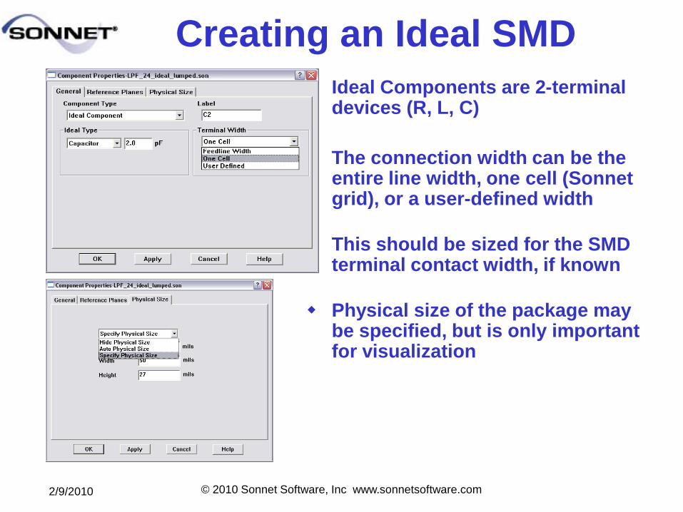
Creating an Ideal SMD
Ideal Components are 2-terminal devices (R, L, C)
The connection width can be the entire line width, one cell (Sonnet grid), or a user-defined width
This should be sized for the SMD terminal contact width, if known
Physical size of the package may be specified, but is only important for visualization
2/9/2010 © 2010 Sonnet Software, Inc www.sonnetsoftware.com
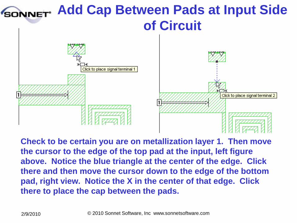
Add Cap Between Pads at Input Side
of Circuit
Check to be certain you are on metallization layer 1. Then move
the cursor to the edge of the top pad at the input, left figure
above. Notice the blue triangle at the center of the edge. Click
there and then move the cursor down to the edge of the bottom
pad, right view. Notice the X in the center of that edge. Click
there to place the cap between the pads.
2/9/2010 © 2010 Sonnet Software, Inc www.sonnetsoftware.com
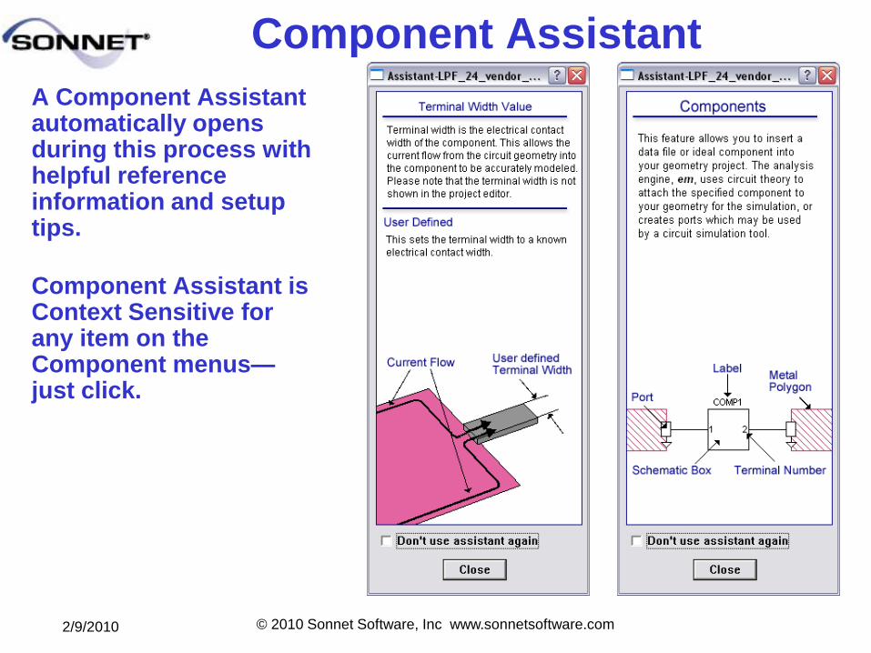
Component Assistant
A Component Assistant automatically opens during this process with helpful reference information and setup tips.
Component Assistant is Context Sensitive for any item on the Component menus—just click.
2/9/2010 © 2010 Sonnet Software, Inc www.sonnetsoftware.com
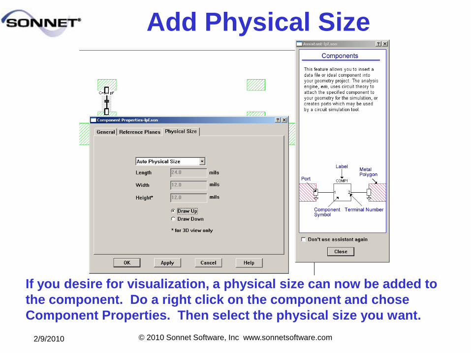
Add Physical Size
If you desire for visualization, a physical size can now be added to
the component. Do a right click on the component and chose
Component Properties. Then select the physical size you want.
2/9/2010 © 2010 Sonnet Software, Inc www.sonnetsoftware.com
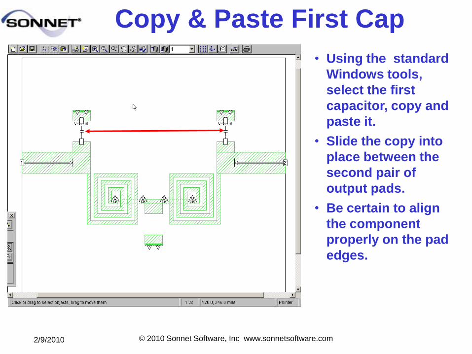
Copy & Paste First Cap
• Using the standard
Windows tools,
select the first
capacitor, copy and
paste it.
• Slide the copy into
place between the
second pair of
output pads.
• Be certain to align
the component
properly on the pad
edges.
2/9/2010 © 2010 Sonnet Software, Inc www.sonnetsoftware.com
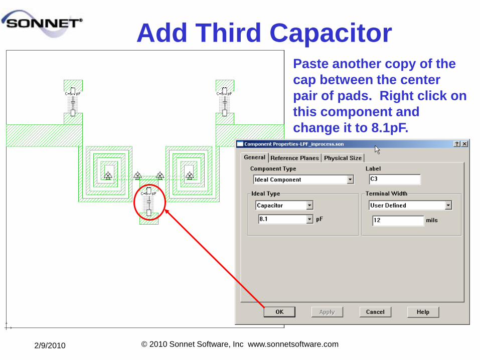
Add Third CapacitorPaste another copy of the
cap between the center
pair of pads. Right click on
this component and
change it to 8.1pF.
2/9/2010 © 2010 Sonnet Software, Inc www.sonnetsoftware.com
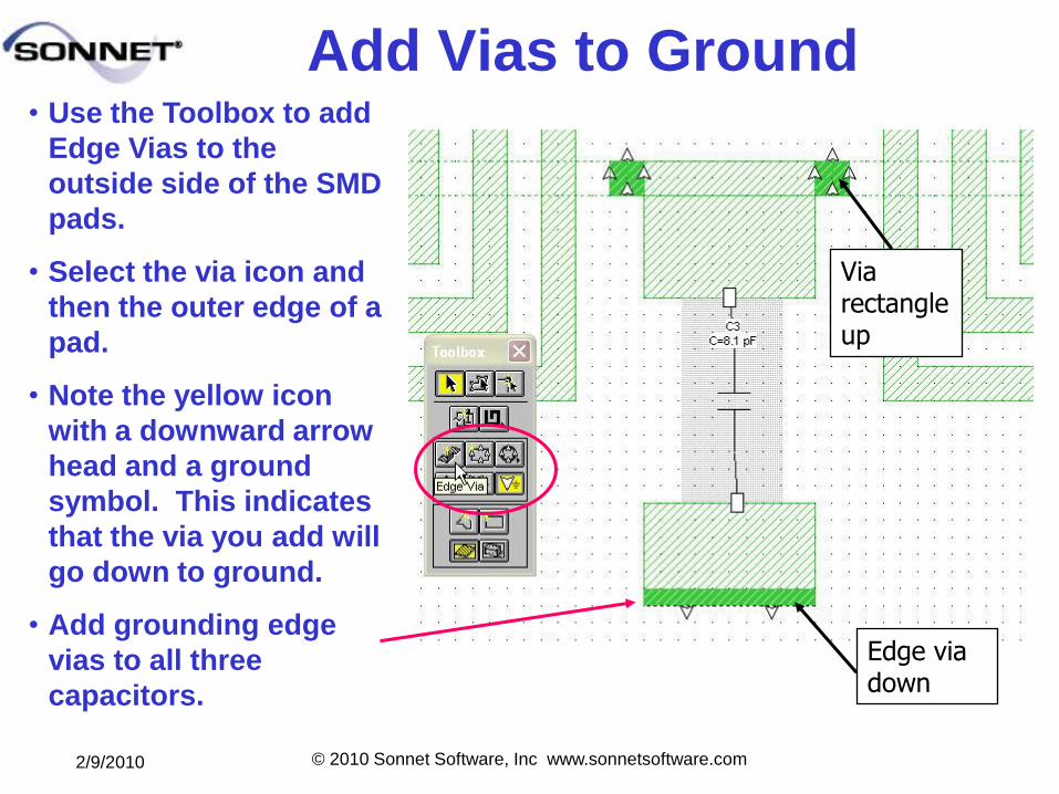
Add Vias to Ground• Use the Toolbox to add
Edge Vias to the
outside side of the SMD
pads.
• Select the via icon and
then the outer edge of a
pad.
• Note the yellow icon
with a downward arrow
head and a ground
symbol. This indicates
that the via you add will
go down to ground.
• Add grounding edge
vias to all three
capacitors.
Edge via down
Via rectangle up
2/9/2010 © 2010 Sonnet Software, Inc www.sonnetsoftware.com
The Connection Matters
SMD Package
Contact TerminalsSMD Package
Current Density under the
package shows discontinuities
around contact pads. Sonnet
characterizes and includes
these discontinuities in your
analysis
RF discontinuities
under package
parts must be
accurately included.
The SMD contact
terminal width is
important to the size
of the discontinuity.
2/9/2010 © 2010 Sonnet Software, Inc www.sonnetsoftware.com
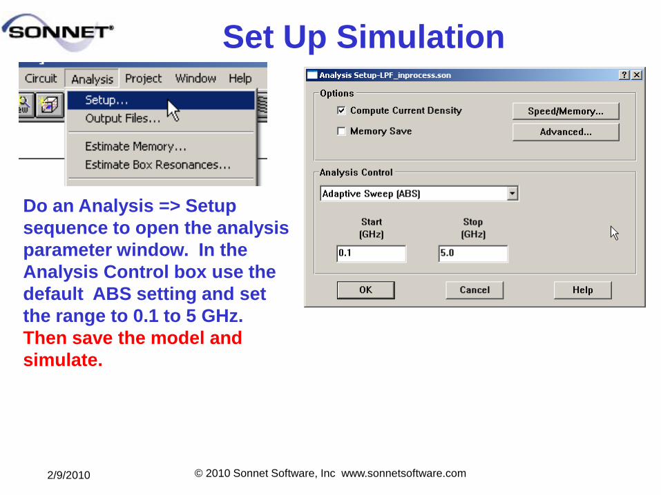
Set Up Simulation
Do an Analysis => Setup
sequence to open the analysis
parameter window. In the
Analysis Control box use the
default ABS setting and set
the range to 0.1 to 5 GHz.
Then save the model and
simulate.
2/9/2010 © 2010 Sonnet Software, Inc www.sonnetsoftware.com
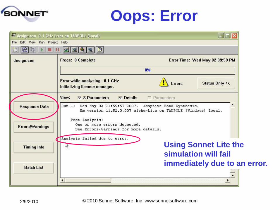
Oops: Error
Using Sonnet Lite the
simulation will fail
immediately due to an error.
2/9/2010 © 2010 Sonnet Software, Inc www.sonnetsoftware.com
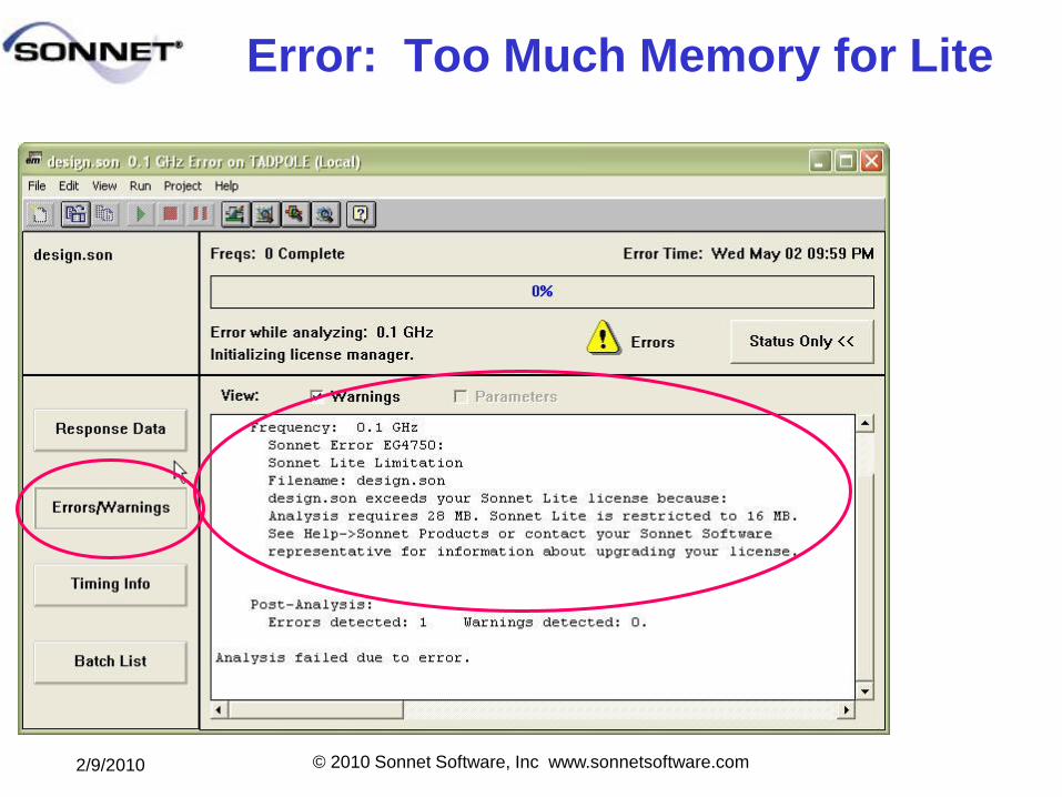
Error: Too Much Memory for Lite
2/9/2010 © 2010 Sonnet Software, Inc www.sonnetsoftware.com
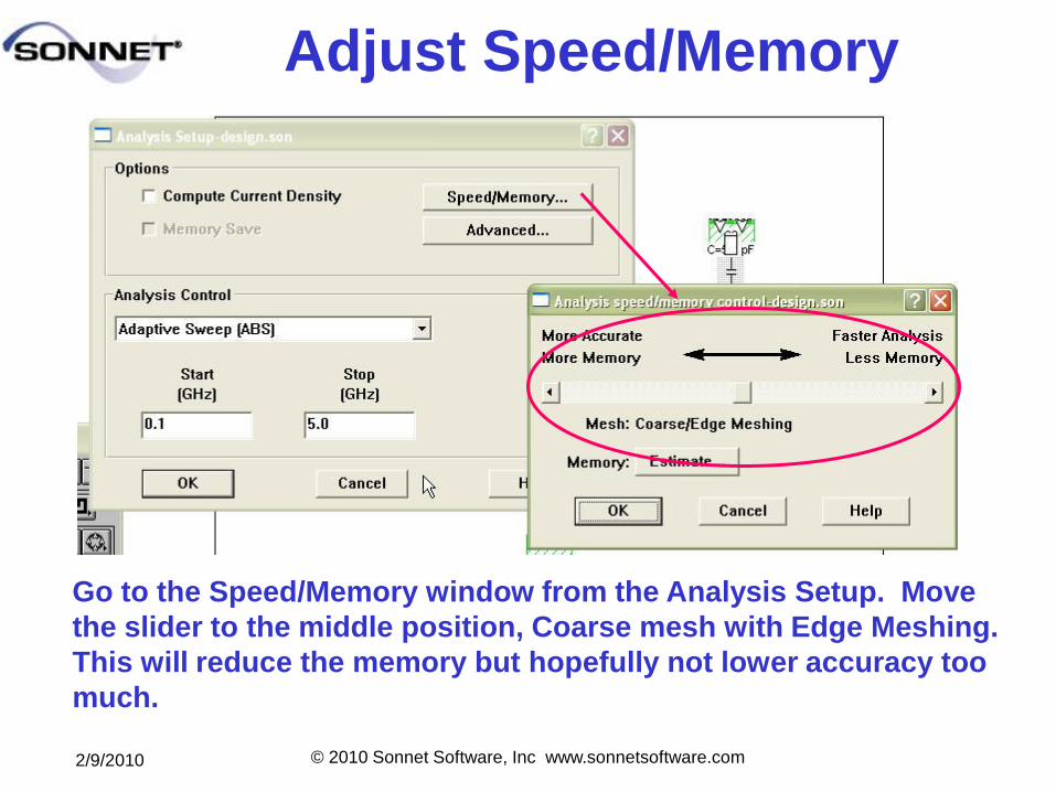
Adjust Speed/Memory
Go to the Speed/Memory window from the Analysis Setup. Move
the slider to the middle position, Coarse mesh with Edge Meshing.
This will reduce the memory but hopefully not lower accuracy too
much.
2/9/2010 © 2010 Sonnet Software, Inc www.sonnetsoftware.com
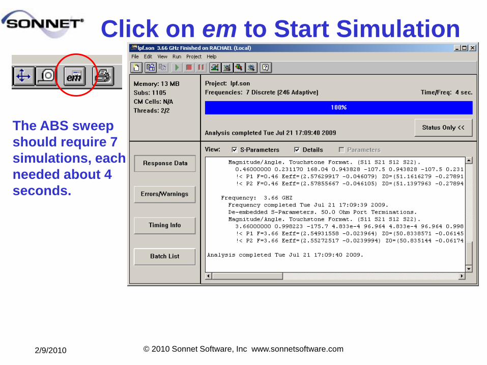
Click on em to Start Simulation
The ABS sweep
should require 7
simulations, each
needed about 4
seconds.
2/9/2010 © 2010 Sonnet Software, Inc www.sonnetsoftware.com
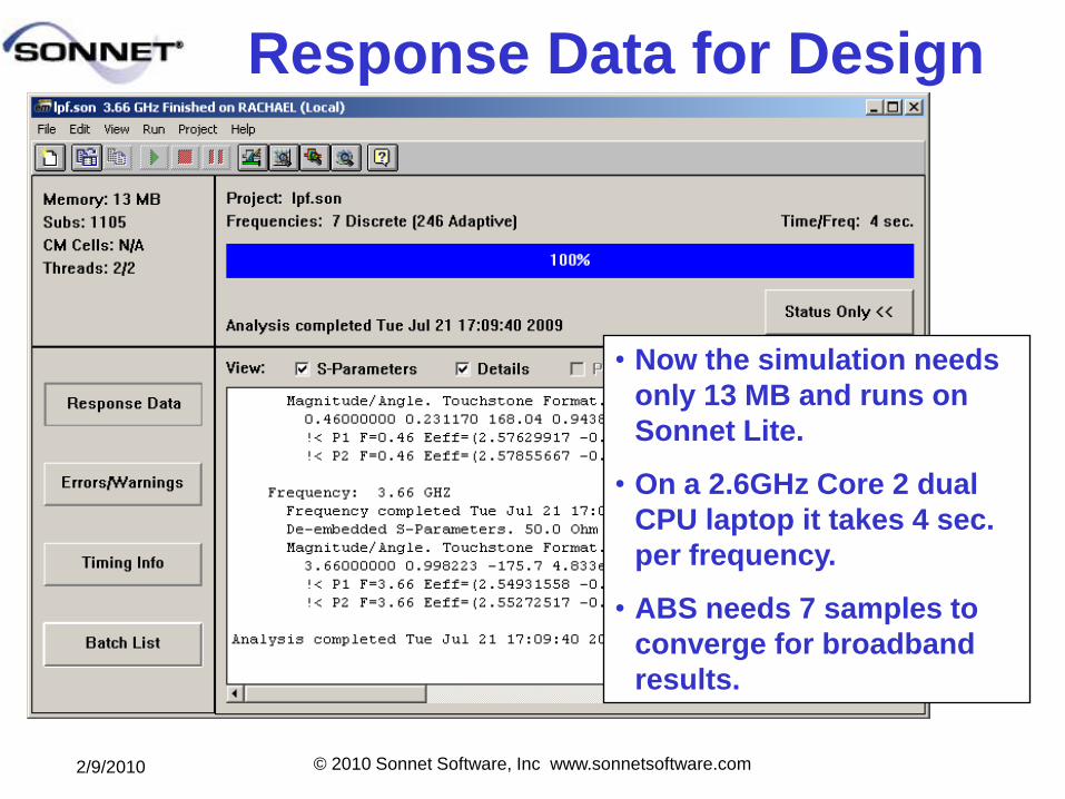
Response Data for Design
• Now the simulation needs
only 13 MB and runs on
Sonnet Lite.
• On a 2.6GHz Core 2 dual
CPU laptop it takes 4 sec.
per frequency.
• ABS needs 7 samples to
converge for broadband
results.
2/9/2010 © 2010 Sonnet Software, Inc www.sonnetsoftware.com
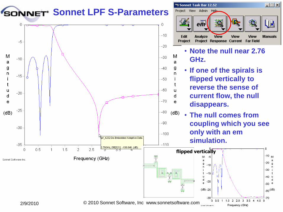
Sonnet LPF S-Parameters
• Note the null near 2.76
GHz.
• If one of the spirals is
flipped vertically to
reverse the sense of
current flow, the null
disappears.
• The null comes from
coupling which you see
only with an em
simulation.
flipped vertically
2/9/2010 © 2010 Sonnet Software, Inc www.sonnetsoftware.com
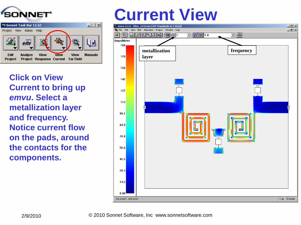
Current View
Click on View
Current to bring up
emvu. Select a
metallization layer
and frequency.
Notice current flow
on the pads, around
the contacts for the
components.
metallization
layer
frequency
2/9/2010 © 2010 Sonnet Software, Inc www.sonnetsoftware.com
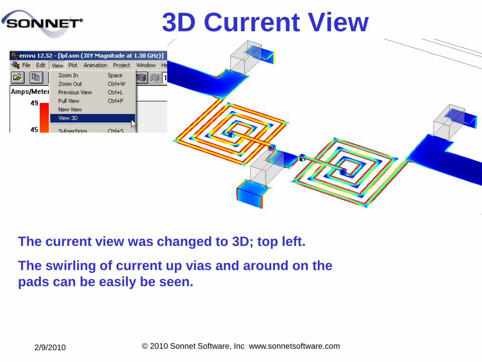
3D Current View
The current view was changed to 3D; top left.
The swirling of current up vias and around on the
pads can be easily be seen.
2/9/2010 © 2010 Sonnet Software, Inc www.sonnetsoftware.com
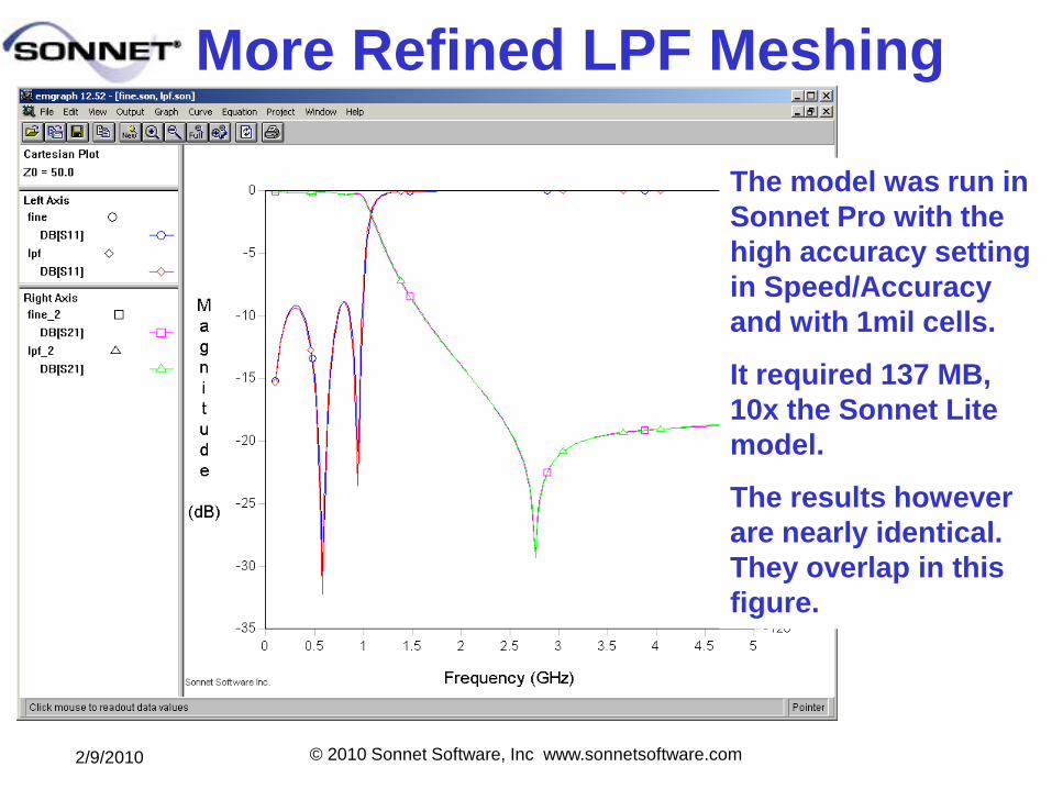
More Refined LPF Meshing
The model was run in
Sonnet Pro with the
high accuracy setting
in Speed/Accuracy
and with 1mil cells.
It required 137 MB,
10x the Sonnet Lite
model.
The results however
are nearly identical.
They overlap in this
figure.
2/9/2010 © 2010 Sonnet Software, Inc www.sonnetsoftware.com
What have we learned?
1. Ideal Components make it very easy to run initial prototype simulations that include all EM effects of the interconnects and vias.
2. Vendor models (Data File Components) can be added for realistic circuit modeling.
3. Ports-Only Components let you build EM models for full layout and leave connection ports where you can add your devices in a circuit simulation framework.
4. Current Density can show the effects of the Components.
5. Sonnet Components put EM simulation to the front-end of high frequency circuit design.