Embed Size (px)
Citation preview
© 2012 Armand J. Chaput
Some Thoughts on Closing the VSP Air Vehicle Performance Loop
Inaugural VSP Workshop, San Luis Obispo, CA
Armand J. Chaput
Department of Aerospace Engineering and Engineering Mechanics, University of Texas at Austin
24 August 2012
© 2012 Armand J. Chaput
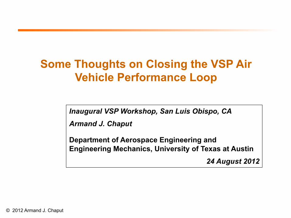
• Physics-based, conceptual level, multi-discipline air system design and analysis spreadsheet
• Developed as an educational tool to support student exploration of a wide range of unmanned air system (UAS) design and operational concepts
• No laborious input data preparation and/or hand calculations - Go from initial concept to complete vehicle sized to
standard mission rules in < 1 hour • Designed for concept exploration and trade studies
Where My Thoughts Started - Rapid Air System Concept Exploration (RASCE)
© 2012 Armand J. Chaput
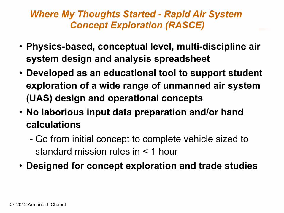
Methodology Overview
Overall problem definition - Concepts of operation - Mission requirements - Engine type - Initial estimates
Aerodynamics - Input
- CLmax (no flaps) - CLt/o - Trim drag factor - Laminar fractions
- Rn⇒Cfe⇒Drag Build-up - Parabolic polar⇒CDi - Parametric comparisons
Propulsion - Input
- Specific weight, density - Cycle parameters - Installation losses
- Speed and altitude effects - Parametric comparisons
Geometry - Parametric Inputs - Parametric Models
- Fuselage(s) - Nacelle(s) - Wings - Tails - Pods
- Wetted area and volume
Performance - Input
- Mission definition - Calculate
- Takeoff - Climb - Turn - Accelerate - Cruise - Loiter - Land - Fuel req’d or remaining
- Parametric comparisons
Mass Properties - Input
- Payload weight - Subsystem fractions - Airframe unit weights - Misc weights
- Weight convergence - Parametric comparisons
Integrated Performance - Mission convergence - Requirement convergence - Parametric comparisons - Parametric adjustments
Converged solution - System performance
- Trade Studies - System optimization
Geo
met
ry a
nd m
ass
mod
els
itera
te to
geth
er to
ach
ieve
con
verg
ence
Overall Parametrics - Wing loading - Fuel fraction - Power or thrust-to-weight - Weight, volume, speed margins
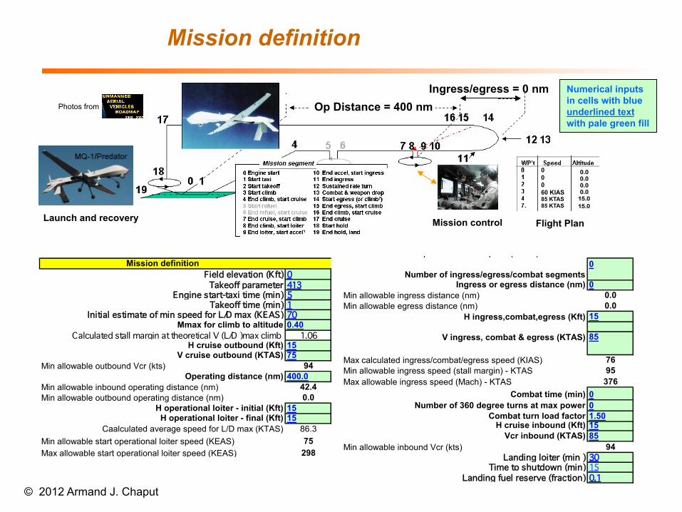
Mission definition
© 2012 Armand J. Chaput
Launch and recovery Mission control Flight Plan
60 KIAS60 KIAS60 KIAS60 KIAS
00060 KIAS60 KTAS60 KTAS
0.0 0.0 0.0 0.0
15.0 15.0
Numerical inputs in cells with blue underlined text with pale green fill
Op Distance = 400 nm Ingress/egress = 0 nm
Mission definitionField elevation (Kft) 0Takeoff parameter 320
Engine start-taxi time (min) 5Takeoff time (min) 1
Initial estimate of min speed for L/D max (KEAS) 70Mmax for climb to altitude 0.40
Calculated stall margin at theoretical V (L/D )max climb 1.10H cruise outbound (Kft) 15
V cruise outbound (KTAS) 85Min allowable outbound Vcr (kts) 107
Operating distance (nm) 400.0Min allowable inbound operating distance (nm) 76.1Min allowable outbound operating distance (nm) 0.0
H operational loiter - initial (Kft) 15H operational loiter - final (Kft) 15
Caalculated average speed for L/D max (KTAS) 88.9Min allowable start operational loiter speed (KEAS) 75Max allowable start operational loiter speed (KEAS) 298
0
Ingress or egress distance (nm) 0Min allowable ingress distance (nm) 0.0Min allowable egress distance (nm) 0.0
15
85
Max calculated ingress/combat/egress speed (KIAS) 76Min allowable ingress speed (stall margin) - KTAS 95Max allowable ingress speed (Mach) - KTAS 376
Combat time (min) 0Number of 360 degree turns at max power 0
Combat turn load factor 1.50H cruise inbound (Kft) 15
Vcr inbound (KTAS) 85Min allowable inbound Vcr (kts) 94
Landing loiter (min ) 30Time to shutdown (min) 15
Landing fuel reserve (fraction) 0.1
Number of ingress/egress/combat segments
H ingress,combat,egress (Kft)
V ingress, combat & egress (KTAS)
85 KTAS 85 KTAS
Photos from
Mission definitionField elevation (Kft) 0Takeoff parameter 413
Engine start-taxi time (min) 5Takeoff time (min) 1
Initial estimate of min speed for L/D max (KEAS) 70Mmax for climb to altitude 0.40
Calculated stall margin at theoretical V (L/D )max climb 1.06H cruise outbound (Kft) 15
V cruise outbound (KTAS) 75Min allowable outbound Vcr (kts) 94
Operating distance (nm) 400.0Min allowable inbound operating distance (nm) 42.4Min allowable outbound operating distance (nm) 0.0
H operational loiter - initial (Kft) 15H operational loiter - final (Kft) 15
Caalculated average speed for L/D max (KTAS) 86.3Min allowable start operational loiter speed (KEAS) 75Max allowable start operational loiter speed (KEAS) 298
0
Ingress or egress distance (nm) 0Min allowable ingress distance (nm) 0.0Min allowable egress distance (nm) 0.0
25
85
Max calculated ingress/combat/egress speed (KIAS) 67Min allowable ingress speed (stall margin) - KTAS 101Max allowable ingress speed (Mach) - KTAS 361
Combat time (min) 0Number of 360 degree turns at max power 0
Combat turn load factor 1.50H cruise inbound (Kft) 15
Vcr inbound (KTAS) 75Min allowable inbound Vcr (kts) 83
Landing loiter (min ) 30Time to shutdown (min) 15
Landing fuel reserve (fraction) 0.1
V ingress, combat & egress (KTAS)
Number of ingress/egress/combat segments
H ingress,combat,egress (Kft)
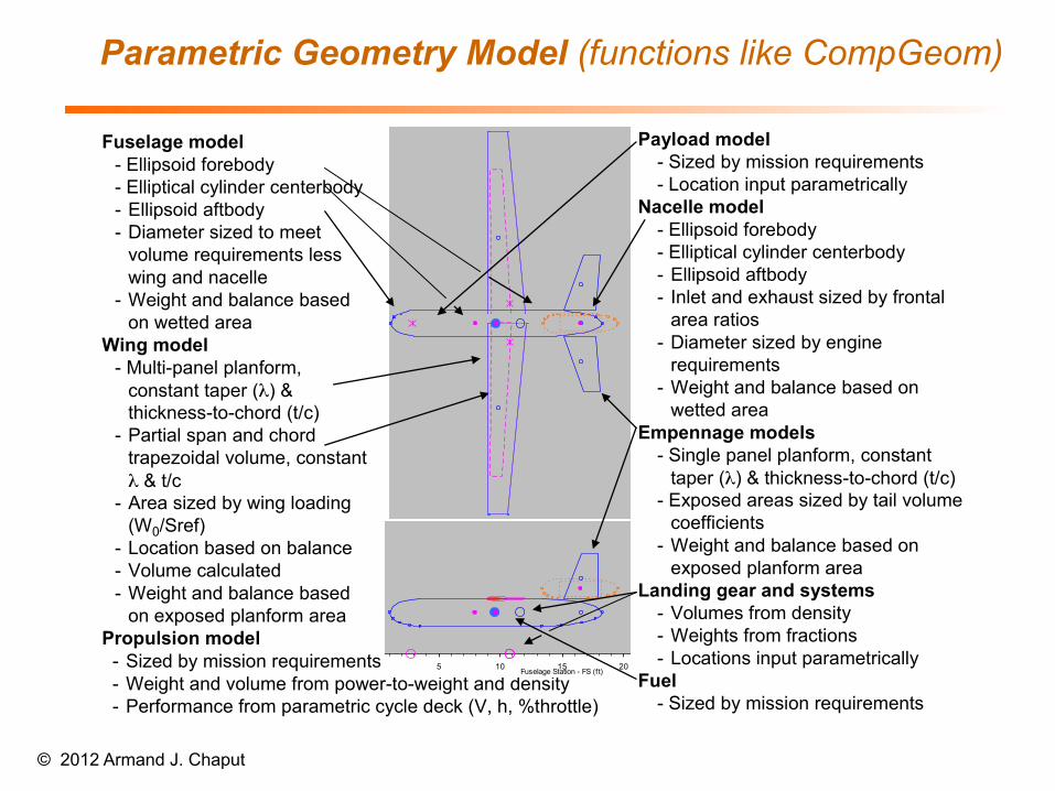
Parametric Geometry Model (functions like CompGeom)
© 2012 Armand J. Chaput
Top View
0
5
10
15
20
25
30
0 5 10 15 20 25 30Fuselage Station (ft)
Butt
line
(ft)
LF uselag eRWing (surrog ate)R F uselag eLNacelleR NacelleR PodLPodEng ineR HT (ea)Gear locationsa.c. locationsOverall c.g .-‐W0C omponent c.g 'sWing tankEquiv V -‐tail (ea)R et'd PayR ig ht wing (as input)Overall c.g . -‐ Wempty
Note - (1) Only 1 each of specified number of fuselage(s), nacelle(s), pod(s), tail(s), engines drawn(2) C.g and landing gear assumed to coincide w ith fuselage CL, multiple fuselage concepts should be adjusted accordingly
Top View
0
5
10
15
20
25
30
0 5 10 15 20 25 30Fuselage Station (ft)
Butt line (ft)
LF uselag eRWing (surrog ate)R F uselag eLNacelleR NacelleR PodLPodEng ineR HT (ea)Gear locationsa.c. locationsOverall c.g .-‐W0C omponent c.g 'sWing tankEquiv V -‐tail (ea)R et'd PayR ig ht wing (as input)Overall c.g . -‐ Wempty
Note - (1) Only 1 each of specified number of fuselage(s), nacelle(s), pod(s), tail(s), engines drawn(2) C.g and landing gear assumed to coincide w ith fuselage CL, multiple fuselage concepts should be adjusted accordingly
Top View
0
5
10
15
20
25
30
0 5 10 15 20 25 30Fuselage Station (ft)
Butt
line
(ft)
LF uselag eRWing (surrog ate)R F uselag eLNacelleR NacelleR PodLPodEng ineR HT (ea)Gear locationsa.c. locationsOverall c.g .-‐W0C omponent c.g 'sWing tankEquiv V -‐tail (ea)R et'd PayR ig ht wing (as input)Overall c.g . -‐ Wempty
Note - (1) Only 1 each of specified number of fuselage(s), nacelle(s), pod(s), tail(s), engines drawn(2) C.g and landing gear assumed to coincide w ith fuselage CL, multiple fuselage concepts should be adjusted accordingly
Top View
0
5
10
15
20
25
30
0 5 10 15 20 25 30Fuselage Station (ft)
Butt line (ft)
LF uselag eRWing (surrog ate)R F uselag eLNacelleR NacelleR PodLPodEng ineR HT (ea)Gear locationsa.c. locationsOverall c.g .-‐W0C omponent c.g 'sWing tankEquiv V -‐tail (ea)R et'd PayR ig ht wing (as input)Overall c.g . -‐ Wempty
Note - (1) Only 1 each of specified number of fuselage(s), nacelle(s), pod(s), tail(s), engines drawn(2) C.g and landing gear assumed to coincide w ith fuselage CL, multiple fuselage concepts should be adjusted accordingly
- Sized by mission requirements- Weight and volume from power-to-weight and density- Performance from parametric cycle deck (V, h, %throttle)
Fuselage model- Ellipsoid forebody- Elliptical cylinder centerbody- Ellipsoid aftbody- Diameter sized to meet
volume requirements less wing and nacelle
- Weight and balance based on wetted area
Wing model- Multi-panel planform,
constant taper (λ) & thickness-to-chord (t/c)
- Partial span and chord trapezoidal volume, constant λ & t/c
- Area sized by wing loading (W0/Sref)
- Location based on balance- Volume calculated- Weight and balance based
on exposed planform areaPropulsion model
Side View
0
5
10
15
20
25
30
0 5 10 15 20 25 30Fuselage Station - FS (ft)
Wat
erlin
e - W
L (ft
)
UF uselag eLF uselag eUNacelleLNacelleUPodLPodEng ineV TGear locationsa.c. locationsOverall c.g . -‐ W0C omponent c.g .'sEquiv V -‐tailWing letR oot chordT ip chordOverall c.g . -‐ We
Note - (1) Only 1 each of specified number of fuselage(s), nacelle(s), pod(s), tail(s), engines drawn(2) C.g and landing gear assumed to coincide w ith fuselage CL, multiple fuselage concepts should be adjusted accordingly
Payload model- Sized by mission requirements- Location input parametrically
Nacelle model- Ellipsoid forebody- Elliptical cylinder centerbody- Ellipsoid aftbody- Inlet and exhaust sized by frontal
area ratios- Diameter sized by engine
requirements- Weight and balance based on
wetted areaEmpennage models
- Single panel planform, constant taper (λ) & thickness-to-chord (t/c)
- Exposed areas sized by tail volume coefficients
- Weight and balance based on exposed planform area
Landing gear and systems- Volumes from density- Weights from fractions- Locations input parametrically
Fuel- Sized by mission requirements
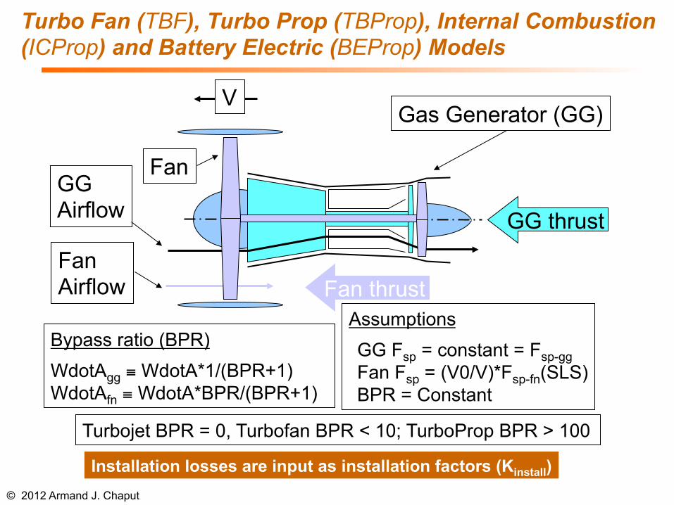
Turbo Fan (TBF), Turbo Prop (TBProp), Internal Combustion (ICProp) and Battery Electric (BEProp) Models
© 2012 Armand J. Chaput
Assumptions
GG Fsp = constant = Fsp-gg Fan Fsp = (V0/V)*Fsp-fn(SLS) BPR = Constant
Gas Generator (GG)
Fan
GG thrust
Fan thrust Fan Airflow
GG Airflow
V
Bypass ratio (BPR)
WdotAgg ≡ WdotA*1/(BPR+1) WdotAfn ≡ WdotA*BPR/(BPR+1)
Turbojet BPR = 0, Turbofan BPR < 10; TurboProp BPR > 100
Installation losses are input as installation factors (Kinstall)
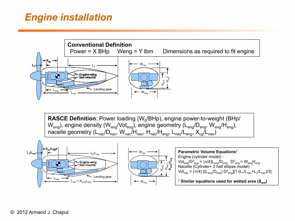
Engine installation
© 2012 Armand J. Chaput
Weng
Wnac
Leng Lnac
Engine-wing box mounts
L1 L2
Landing gear
Xcg
Hen
g Hna
c
Weng
Wnac
Leng Lnac
Engine-wing box mounts
L1 L2
Landing gear
Xcg
Hen
g Hna
c
Weng
Wnac
Leng Lnac
Engine-wing box mounts
L1 L2
Landing gear
Xcg
Hen
g Hna
c
Weng
Wnac
Leng Lnac
Engine-wing box mounts
L1 L2
Landing gear
Xcg
Hen
g Hna
c
Conventional Definition Power = X BHp Weng = Y lbm Dimensions as required to fit engine
Weng
Wnac
LengLnac = KinstxLeng
Engine-wing box mounts
Landing gear
L2/Lnac
Hen
g
L1/Lnac
Xcg/Lnac
Hna
c=
Kin
styH
eng
Weng
Wnac
LengLnac = KinstxLeng
Engine-wing box mounts
Landing gear
L2/Lnac
Hen
g
L1/Lnac
Xcg/Lnac
Hna
c=
Kin
styH
eng
RASCE Definition: Power loading (W0/BHp), engine power-to-weight (BHp/Weng), engine density (Weng/Voleng), engine geometry (Leng/Deng, Weng/Heng), nacelle geometry (Lnac/Dnac, Wnac/Hnac, Hnac/Heng, Lnac/Leng, Xcg/Lnac)
Parametric Volume Equations1 Engine (cylinder model) : Voleng/D3
eng = (π/4)Leng/Deng, D2eng = WengHeng
Nacelle (Cylinder+ 2 half ellipse model) : Volnac = (π/4) [(Leng/Deng) D3
eng][1-(L1/Lnac+L2/Lnac)/3] 1 Similar equations used for wetted area (Swet)
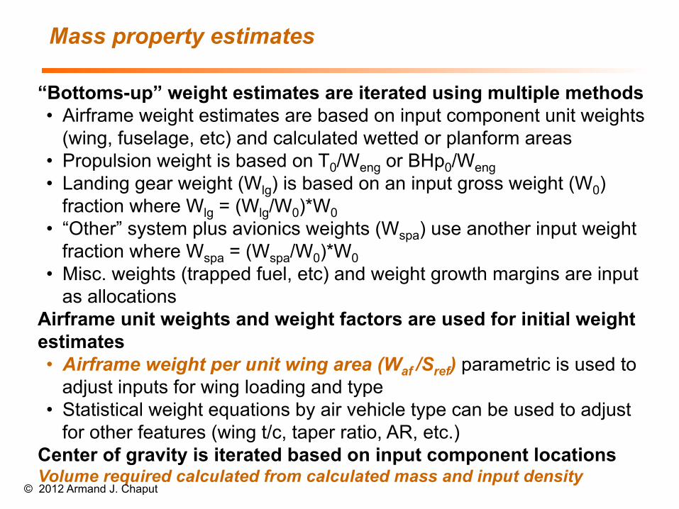
“Bottoms-up” weight estimates are iterated using multiple methods • Airframe weight estimates are based on input component unit weights
(wing, fuselage, etc) and calculated wetted or planform areas • Propulsion weight is based on T0/Weng or BHp0/Weng • Landing gear weight (Wlg) is based on an input gross weight (W0)
fraction where Wlg = (Wlg/W0)*W0 • “Other” system plus avionics weights (Wspa) use another input weight
fraction where Wspa = (Wspa/W0)*W0 • Misc. weights (trapped fuel, etc) and weight growth margins are input
as allocations Airframe unit weights and weight factors are used for initial weight estimates • Airframe weight per unit wing area (Waf /Sref) parametric is used to
adjust inputs for wing loading and type • Statistical weight equations by air vehicle type can be used to adjust
for other features (wing t/c, taper ratio, AR, etc.) Center of gravity is iterated based on input component locations Volume required calculated from calculated mass and input density
Mass property estimates
© 2012 Armand J. Chaput
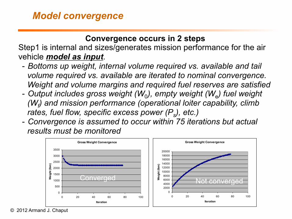
Convergence occurs in 2 steps Step1 is internal and sizes/generates mission performance for the air vehicle model as input. - Bottoms up weight, internal volume required vs. available and tail
volume required vs. available are iterated to nominal convergence. Weight and volume margins and required fuel reserves are satisfied
- Output includes gross weight (W0), empty weight (We) fuel weight (Wf) and mission performance (operational loiter capability, climb rates, fuel flow, specific excess power (Ps), etc.)
- Convergence is assumed to occur within 75 iterations but actual results must be monitored
Model convergence
© 2012 Armand J. Chaput
Gross Weight Convergence
0
500
1000
1500
2000
2500
3000
3500
0 20 40 60 80 100
Iteration
Wei
ght (
lbm
)
Gross Weight Convergence
02000400060008000100001200014000160001800020000
0 20 40 60 80 100
Iteration
Wei
ght (
lbm
)
Converged Not converged
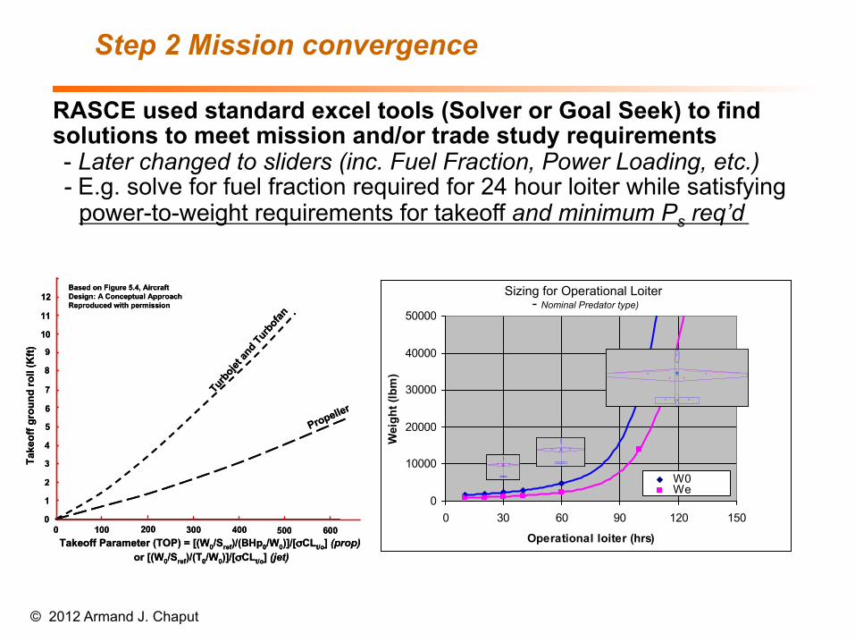
RASCE used standard excel tools (Solver or Goal Seek) to find solutions to meet mission and/or trade study requirements - Later changed to sliders (inc. Fuel Fraction, Power Loading, etc.) - E.g. solve for fuel fraction required for 24 hour loiter while satisfying
power-to-weight requirements for takeoff and minimum Ps req’d
Step 2 Mission convergence
© 2012 Armand J. Chaput
Operational Loiter Sensitivity
0
10000
20000
30000
40000
50000
0 30 60 90 120 150
Operational loiter (hrs)
Wei
ght (
lbm
)
W0WePoly. (We)Poly. (W0)
Top View
0 25 50 75
100
125
025
5075
100125
Fuselage Station (ft)
Butt line (ft)
LFuselageRWing (surrogate)
RFuselage
LNacelle
RNacelle
RPod
LPodEngineRHT (ea)
Gear locations
a.c. locationsOverall c.g.-‐W
0Com
ponent c.g'sWing tank
Equiv V-‐tail (ea)
Ret'd Pay
Right w
ing (as input)Overall c.g. -‐ W
empty
Note - (1) Only 1 each of specified number of fuselage(s), nacelle(s), pod(s), tail(s), engines draw
n(2) C.g and landing gear assumed to coincide w
ith fuselage CL, multiple fuselage concepts should be adjusted accordingly
Top View
0255075100
1250
25
50
75
100
125
Fuselage Station (ft)
Butt line (ft)
LFuselage
RWing (surrogate)
RFuselage
LNacelle
RNacelle
RPod
LPod
Engine
RHT (ea)
Gear locations
a.c. locations
Overall c.g.-‐W0
Component c.g's
Wing tank
Equiv V-‐tail (ea)
Ret'd Pay
Right wing (as input)
Overall c.g. -‐ Wempty
Note - (1) Only 1 each of specified number of fuselage(s), nacelle(s), pod(s), tail(s), engines
drawn
(2) C.g and landing gear assumed to coincide with fuselage CL, multiple fuselage concepts should
be adjusted accordingly
Top View
0 25 50 75
100
125
025
5075
100125
Fuselage Station (ft)
Butt line (ft)
LFuselageRWing (surrogate)
RFuselage
LNacelle
RNacelle
RPod
LPodEngineRHT (ea)
Gear locations
a.c. locationsOverall c.g.-‐W
0Com
ponent c.g'sWing tank
Equiv V-‐tail (ea)
Ret'd Pay
Right w
ing (as input)Overall c.g. -‐ W
empty
Note - (1) Only 1 each of specified number of fuselage(s), nacelle(s), pod(s), tail(s), engines draw
n(2) C.g and landing gear assumed to coincide w
ith fuselage CL, multiple fuselage concepts should be adjusted accordingly
Top View
0255075100
1250
25
50
75
100
125
Fuselage Station (ft)
Butt line (ft)
LFuselage
RWing (surrogate)
RFuselage
LNacelle
RNacelle
RPod
LPod
Engine
RHT (ea)
Gear locations
a.c. locations
Overall c.g.-‐W0
Component c.g's
Wing tank
Equiv V-‐tail (ea)
Ret'd Pay
Right wing (as input)
Overall c.g. -‐ Wempty
Note - (1) Only 1 each of specified number of fuselage(s), nacelle(s), pod(s), tail(s), engines
drawn
(2) C.g and landing gear assumed to coincide with fuselage CL, multiple fuselage concepts should
be adjusted accordingly
Sizing for Operational Loiter- Nominal Predator type)
Operational Loiter Sensitivity
0
10000
20000
30000
40000
50000
0 30 60 90 120 150
Operational loiter (hrs)
Wei
ght (
lbm
)
W0WePoly. (We)Poly. (W0)
Top View
0 25 50 75
100
125
025
5075
100125
Fuselage Station (ft)
Butt line (ft)
LFuselageRWing (surrogate)
RFuselage
LNacelle
RNacelle
RPod
LPodEngineRHT (ea)
Gear locations
a.c. locationsOverall c.g.-‐W
0Com
ponent c.g'sWing tank
Equiv V-‐tail (ea)
Ret'd Pay
Right w
ing (as input)Overall c.g. -‐ W
empty
Note - (1) Only 1 each of specified number of fuselage(s), nacelle(s), pod(s), tail(s), engines draw
n(2) C.g and landing gear assumed to coincide w
ith fuselage CL, multiple fuselage concepts should be adjusted accordingly
Top View
0255075100
1250
25
50
75
100
125
Fuselage Station (ft)
Butt line (ft)
LFuselage
RWing (surrogate)
RFuselage
LNacelle
RNacelle
RPod
LPod
Engine
RHT (ea)
Gear locations
a.c. locations
Overall c.g.-‐W0
Component c.g's
Wing tank
Equiv V-‐tail (ea)
Ret'd Pay
Right wing (as input)
Overall c.g. -‐ Wempty
Note - (1) Only 1 each of specified number of fuselage(s), nacelle(s), pod(s), tail(s), engines
drawn
(2) C.g and landing gear assumed to coincide with fuselage CL, multiple fuselage concepts should
be adjusted accordingly
Top View
0255075100
1250
25
50
75
100
125
Fuselage Station (ft)
Butt line (ft)
LFuselage
RWing (surrogate)
RFuselage
LNacelle
RNacelle
RPod
LPod
Engine
RHT (ea)
Gear locations
a.c. locations
Overall c.g.-‐W0
Component c.g's
Wing tank
Equiv V-‐tail (ea)
Ret'd Pay
Right wing (as input)
Overall c.g. -‐ Wempty
Note - (1) Only 1 each of specified number of fuselage(s), nacelle(s), pod(s), tail(s), engines
drawn
(2) C.g and landing gear assumed to coincide with fuselage CL, multiple fuselage concepts should
be adjusted accordingly
Top View
0 25 50 75
100
125
025
5075
100125
Fuselage Station (ft)
Butt line (ft)
LFuselageRWing (surrogate)
RFuselage
LNacelle
RNacelle
RPod
LPodEngineRHT (ea)
Gear locations
a.c. locationsOverall c.g.-‐W
0Com
ponent c.g'sWing tank
Equiv V-‐tail (ea)
Ret'd Pay
Right w
ing (as input)Overall c.g. -‐ W
empty
Note - (1) Only 1 each of specified number of fuselage(s), nacelle(s), pod(s), tail(s), engines draw
n(2) C.g and landing gear assumed to coincide w
ith fuselage CL, multiple fuselage concepts should be adjusted accordingly
Top View
0 25 50 75
100
125
025
5075
100125
Fuselage Station (ft)
Butt line (ft)
LFuselageRWing (surrogate)
RFuselage
LNacelle
RNacelle
RPod
LPodEngineRHT (ea)
Gear locations
a.c. locationsOverall c.g.-‐W
0Com
ponent c.g'sWing tank
Equiv V-‐tail (ea)
Ret'd Pay
Right w
ing (as input)Overall c.g. -‐ W
empty
Note - (1) Only 1 each of specified number of fuselage(s), nacelle(s), pod(s), tail(s), engines draw
n(2) C.g and landing gear assumed to coincide w
ith fuselage CL, multiple fuselage concepts should be adjusted accordingly
Top View
0255075100
1250
25
50
75
100
125
Fuselage Station (ft)
Butt line (ft)
LFuselage
RWing (surrogate)
RFuselage
LNacelle
RNacelle
RPod
LPod
Engine
RHT (ea)
Gear locations
a.c. locations
Overall c.g.-‐W0
Component c.g's
Wing tank
Equiv V-‐tail (ea)
Ret'd Pay
Right wing (as input)
Overall c.g. -‐ Wempty
Note - (1) Only 1 each of specified number of fuselage(s), nacelle(s), pod(s), tail(s), engines
drawn
(2) C.g and landing gear assumed to coincide with fuselage CL, multiple fuselage concepts should
be adjusted accordingly
Operational Loiter Sensitivity
0
10000
20000
30000
40000
50000
0 30 60 90 120 150
Operational loiter (hrs)
Wei
ght (
lbm
)
W0WePoly. (We)Poly. (W0)
Top View
0 25 50 75
100
125
025
5075
100125
Fuselage Station (ft)
Butt line (ft)
LFuselageRWing (surrogate)
RFuselage
LNacelle
RNacelle
RPod
LPodEngineRHT (ea)
Gear locations
a.c. locationsOverall c.g.-‐W
0Com
ponent c.g'sWing tank
Equiv V-‐tail (ea)
Ret'd Pay
Right w
ing (as input)Overall c.g. -‐ W
empty
Note - (1) Only 1 each of specified number of fuselage(s), nacelle(s), pod(s), tail(s), engines draw
n(2) C.g and landing gear assumed to coincide w
ith fuselage CL, multiple fuselage concepts should be adjusted accordingly
Top View
0255075100
1250
25
50
75
100
125
Fuselage Station (ft)
Butt line (ft)
LFuselage
RWing (surrogate)
RFuselage
LNacelle
RNacelle
RPod
LPod
Engine
RHT (ea)
Gear locations
a.c. locations
Overall c.g.-‐W0
Component c.g's
Wing tank
Equiv V-‐tail (ea)
Ret'd Pay
Right wing (as input)
Overall c.g. -‐ Wempty
Note - (1) Only 1 each of specified number of fuselage(s), nacelle(s), pod(s), tail(s), engines
drawn
(2) C.g and landing gear assumed to coincide with fuselage CL, multiple fuselage concepts should
be adjusted accordingly
Top View
0 25 50 75
100
125
025
5075
100125
Fuselage Station (ft)
Butt line (ft)
LFuselageRWing (surrogate)
RFuselage
LNacelle
RNacelle
RPod
LPodEngineRHT (ea)
Gear locations
a.c. locationsOverall c.g.-‐W
0Com
ponent c.g'sWing tank
Equiv V-‐tail (ea)
Ret'd Pay
Right w
ing (as input)Overall c.g. -‐ W
empty
Note - (1) Only 1 each of specified number of fuselage(s), nacelle(s), pod(s), tail(s), engines draw
n(2) C.g and landing gear assumed to coincide w
ith fuselage CL, multiple fuselage concepts should be adjusted accordingly
Top View
0255075100
1250
25
50
75
100
125
Fuselage Station (ft)
Butt line (ft)
LFuselage
RWing (surrogate)
RFuselage
LNacelle
RNacelle
RPod
LPod
Engine
RHT (ea)
Gear locations
a.c. locations
Overall c.g.-‐W0
Component c.g's
Wing tank
Equiv V-‐tail (ea)
Ret'd Pay
Right wing (as input)
Overall c.g. -‐ Wempty
Note - (1) Only 1 each of specified number of fuselage(s), nacelle(s), pod(s), tail(s), engines
drawn
(2) C.g and landing gear assumed to coincide with fuselage CL, multiple fuselage concepts should
be adjusted accordingly
Top View
0 25 50 75
100
125
025
5075
100125
Fuselage Station (ft)
Butt line (ft)
LFuselageRWing (surrogate)
RFuselage
LNacelle
RNacelle
RPod
LPodEngineRHT (ea)
Gear locations
a.c. locationsOverall c.g.-‐W
0Com
ponent c.g'sWing tank
Equiv V-‐tail (ea)
Ret'd Pay
Right w
ing (as input)Overall c.g. -‐ W
empty
Note - (1) Only 1 each of specified number of fuselage(s), nacelle(s), pod(s), tail(s), engines draw
n(2) C.g and landing gear assumed to coincide w
ith fuselage CL, multiple fuselage concepts should be adjusted accordingly
Top View
0255075100
1250
25
50
75
100
125
Fuselage Station (ft)
Butt line (ft)
LFuselage
RWing (surrogate)
RFuselage
LNacelle
RNacelle
RPod
LPod
Engine
RHT (ea)
Gear locations
a.c. locations
Overall c.g.-‐W0
Component c.g's
Wing tank
Equiv V-‐tail (ea)
Ret'd Pay
Right wing (as input)
Overall c.g. -‐ Wempty
Note - (1) Only 1 each of specified number of fuselage(s), nacelle(s), pod(s), tail(s), engines
drawn
(2) C.g and landing gear assumed to coincide with fuselage CL, multiple fuselage concepts should
be adjusted accordingly
Top View
0 25 50 75
100
125
025
5075
100125
Fuselage Station (ft)
Butt line (ft)
LFuselageRWing (surrogate)
RFuselage
LNacelle
RNacelle
RPod
LPodEngineRHT (ea)
Gear locations
a.c. locationsOverall c.g.-‐W
0Com
ponent c.g'sWing tank
Equiv V-‐tail (ea)
Ret'd Pay
Right w
ing (as input)Overall c.g. -‐ W
empty
Note - (1) Only 1 each of specified number of fuselage(s), nacelle(s), pod(s), tail(s), engines draw
n(2) C.g and landing gear assumed to coincide w
ith fuselage CL, multiple fuselage concepts should be adjusted accordingly
Top View
0255075100
1250
25
50
75
100
125
Fuselage Station (ft)
Butt line (ft)
LFuselage
RWing (surrogate)
RFuselage
LNacelle
RNacelle
RPod
LPod
Engine
RHT (ea)
Gear locations
a.c. locations
Overall c.g.-‐W0
Component c.g's
Wing tank
Equiv V-‐tail (ea)
Ret'd Pay
Right wing (as input)
Overall c.g. -‐ Wempty
Note - (1) Only 1 each of specified number of fuselage(s), nacelle(s), pod(s), tail(s), engines
drawn
(2) C.g and landing gear assumed to coincide with fuselage CL, multiple fuselage concepts should
be adjusted accordingly
Sizing for Operational Loiter- Nominal Predator type)
0 100 200 300 400 500 600
1
2
3
0
5
6
7
4
9
10
11
8
12
Take
off g
roun
d ro
ll (K
ft)
Takeoff Parameter (TOP) = [(W0/Sref)/(BHp0/W0)]/[σCLt/o] (prop)or [(W0/Sref)/(T0/W0)]/[σCLt/o] (jet)
Propeller
Turb
ojet a
nd Tu
rbofa
nBased on Figure 5.4, Aircraft Design: A Conceptual Approach Reproduced with permission
Post Solution Component locations vs. volume
© 2012 Armand J. Chaput
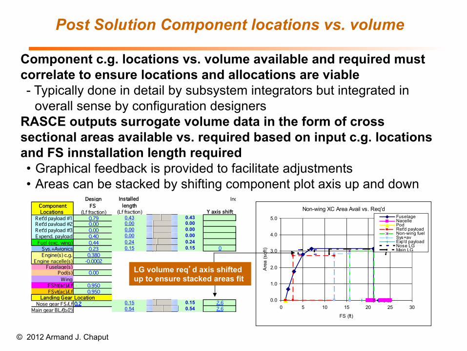
Component c.g. locations vs. volume available and required must correlate to ensure locations and allocations are viable - Typically done in detail by subsystem integrators but integrated in
overall sense by configuration designers RASCE outputs surrogate volume data in the form of cross sectional areas available vs. required based on input c.g. locations and FS innstallation length required • Graphical feedback is provided to facilitate adjustments • Areas can be stacked by shifting component plot axis up and down
Design Fallout Installed Include wing sweep in HT TVC? (Y = 1)Component FS FS BL WL lengthLocations (Lf fraction) (span fraction) (Hf/2 fraction) (Lf fraction) Y axis shift
Ret'd payload #1 0.79 0.79 0.43 0 100 43 0.43Ret'd payload #2 0.00 0.00 0.00 0 100 0 0.00 NengRet'd payload #3 0.00 0.00 0.00 0 100 0 0.00Expend. payload 0.40 0.40 0.00 0 100 0 0.00Fuel (exc. wing) 0.44 0.24 0 100 24 0.24
Sys.+Avionics 0.23 0.15 0.0 100.0 15 0.15 0Engine(s) c.g. 0.380 0 0.00
Engine nacelle(s) -0.0002Fuselage(s) 0
Pod(s) 0.00 0 -0.08Wing 0.00
FSht(ac)/Lf 0.950 0.04 0FSvt(ac)/Lf 0.950 0 0.60
Landing Gear LocationNose gear FS/Lf 0.2 0.15 0.0 100.0 15 0.15 2.6
Main gear BL/(b/2) 0.2 0.54 0.0 100.0 54 0.54 2.6
Installed Include wing sweep in HT TVC? (Y = 1)length
(Lf fraction) Y axis shift0.43 0.430.00 0.00 Neng0.00 0.000.00 0.000.24 0.240.15 0.15 0
0.15 0.15 2.60.54 0.54 2.6
Non-wing XC Area Avail vs. Req'd
0.0
1.0
2.0
3.0
4.0
5.0
0 5 10 15 20 25 30
FS (ft)
Are
a (s
qft)
FuselageNacellePodRet'd payloadNon-wing fuelSys+avExp'd payloadNose LGMain LG
LG volume req’d axis shifted up to ensure stacked areas fit
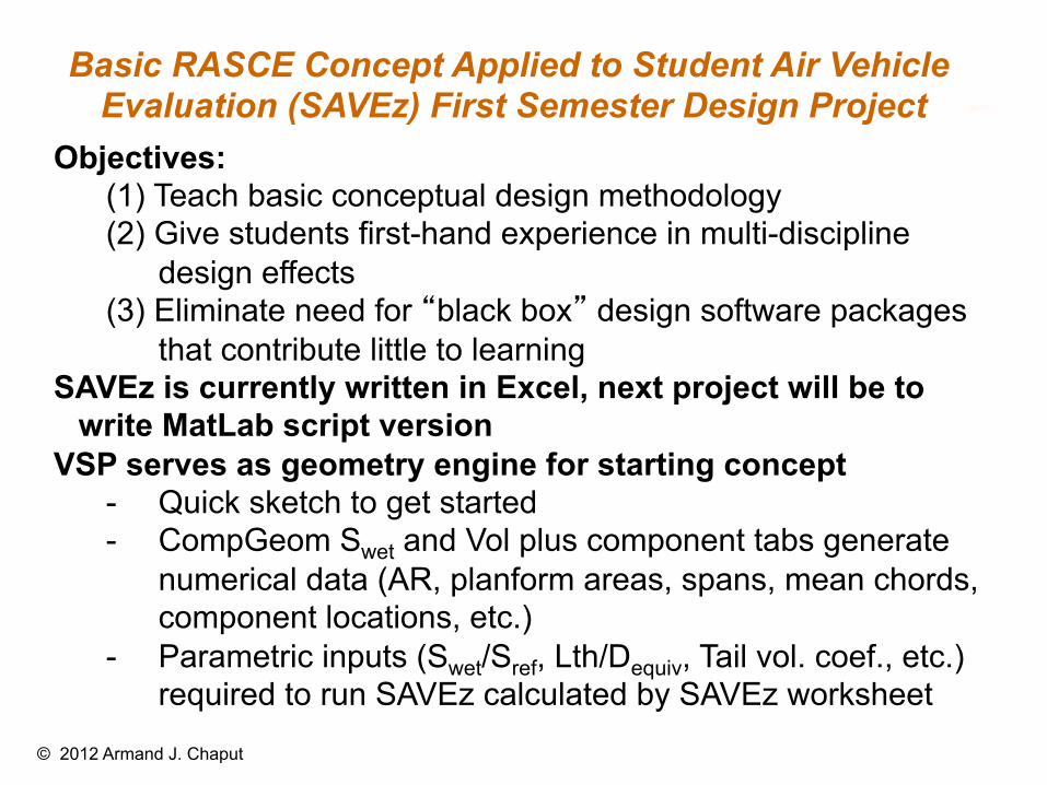
Basic RASCE Concept Applied to Student Air Vehicle Evaluation (SAVEz) First Semester Design Project
© 2012 Armand J. Chaput
Objectives: (1) Teach basic conceptual design methodology (2) Give students first-hand experience in multi-discipline
design effects (3) Eliminate need for “black box” design software packages
that contribute little to learning SAVEz is currently written in Excel, next project will be to
write MatLab script version VSP serves as geometry engine for starting concept
- Quick sketch to get started - CompGeom Swet and Vol plus component tabs generate
numerical data (AR, planform areas, spans, mean chords, component locations, etc.)
- Parametric inputs (Swet/Sref, Lth/Dequiv, Tail vol. coef., etc.) required to run SAVEz calculated by SAVEz worksheet
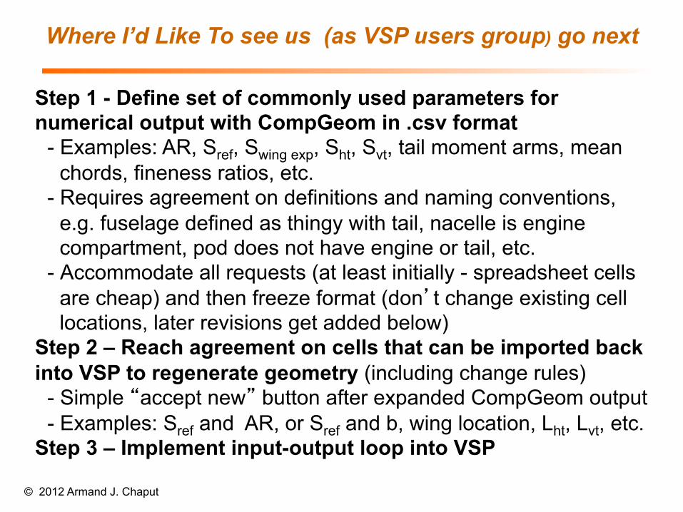
Where I’d Like To see us (as VSP users group) go next
© 2012 Armand J. Chaput
Step 1 - Define set of commonly used parameters for numerical output with CompGeom in .csv format
- Examples: AR, Sref, Swing exp, Sht, Svt, tail moment arms, mean chords, fineness ratios, etc.
- Requires agreement on definitions and naming conventions, e.g. fuselage defined as thingy with tail, nacelle is engine compartment, pod does not have engine or tail, etc.
- Accommodate all requests (at least initially - spreadsheet cells are cheap) and then freeze format (don’t change existing cell locations, later revisions get added below)
Step 2 – Reach agreement on cells that can be imported back into VSP to regenerate geometry (including change rules)
- Simple “accept new” button after expanded CompGeom output - Examples: Sref and AR, or Sref and b, wing location, Lht, Lvt, etc.
Step 3 – Implement input-output loop into VSP