Embed Size (px)
Citation preview
SOME PROBLEMS OF IMPROVEMENT OF FUEL EFFICIENCY AND EMISSIONS IN INTERNAL COMBUSTION ENGINES
Antoni Jankowski
Institute of Aeronautics, BK Al. Krakowska 110/114, 02-256 Warszawa, [email protected]
Alexander Sandel
The National Automotive Center, Warren, MI 48397-5000, USA, [email protected]
Janusz Sęczyk
Institute of Aeronautics, BK Al. Krakowska 110/114, 02-256 Warszawa, [email protected]
Barbara Siemińska-Jankowska
Institute of Aeronautics, BK Al. Krakowska 110/114, 02-256 Warszawa, [email protected]
Abstract
Analysis of some design for both compression ignition and spark ignition engines which give improvement from point of view fuel efficiency and pollutant emission including CO2 are presented in the paper. Actual and future standards requirement for pollutant emissions and CO2 as well test procedures, generally for light duty car for Californian standards and European standards are overviedwed. Especially common rail system for compression ignition and spark ignition engines were presented. Air assist system which can be applied for four stroke and two stroke engines was described too. Gasoline direct injection system which operate in 2 modes: lean burn mixture when engine run with a part load and homogeneous charge with stoichiometric mixture when engine run with high load is presented. Lean stratified mixture is realized as a late fuel injection during compression stroke but homogenous charge is realized as a early fuel injection during induction stroke. Lean mixtures require to apply special de - NOx catalytyst which joined with three way catalytyst (TWC) enable meet of standard requirements concerning exhaust emission.
Investigation concerning some solutions of mixture preparation process and combustion were conducted. Mixture preparation process investigations were conducted with laser Doppler equipment LDV (3D) and PDPA. Combustion processes ware conducted in constant volume chamber. During combustion process testing the flow field, fuel droplet dimension and structure of fuel spray profitable for ignition process close to spark plug was determined. If velocity of the droplet in spark plug was near zero and droplet dimension were small repeatable ignition for lean mixture was obtained.
1. INTRODUCTION
Global pollution caused by transport consists primarily of the emissions from transport systems during manufacture, operation and disposal of the greenhouse gases. These gases include the direct greenhouse gases such as carbon dioxide and methane, the ozone precursors such as hydrocarbons and the nitrogen oxides, and carbon monoxide which has an indirect effect on greenhouse gas production. The problem of global pollution from transport activities is centered on the use of fossil fuels for transport. These fuels are mainly in the form of gasoline
333
Journal of KONES Internal Combustion Engines 2002 No. 1‐2 ISSN 1231 ‐ 4005
and diesel oil for road transport, kerosene for air transport, and diesel oil for rail transport, industrial application, shipping etc. Greenhouse gases are defined as those gases which do not absorb solar radiation around its wavelength of peak intensity in the visible spectrum, but do absorb the infrared radiation scattered from the earth's surface. Thus they alter the radiation balance of the earth, and they contribute to an increase in global atmospheric temperatures due to enhanced absorption of infrared radiation. The consequences of this global warming are thought to include changes in climate patterns, a re-balancing of eco-systems, additional melting of the polar ice-caps and rising sea-levels due to thermal expansion of the oceans.
Impact of greenhouse gases from the transport is approximately 20%, of the total greenhouse, the use of gasoline fuels in road transport is the most important – 52%, diesel fuels contribute 26% and aircraft -19%.
In this way the emission of CO2 from transport has become an increasingly serious problem to the greenhouse effect. The reduction of fuel consumption is one of the most effective means for manufacturers to resolve this problem. Among the methods to reduce fuel consumption, lean burn is well known as an effective approach. However, operation of an engine with a lean mixture requires swirl or other means to improve and stabilize the combustion which consequently decreases the rated output power due to the low flow coefficient of the intake port . Furthermore, the exhaust gases from lean-burn engines produce an oxygenated condition in which a three-way catalyst does not work effectively, thereby making it difficult to reduce NOx emission to a satisfactory level.
With the adoption of the Low Emission Vehicles (LEV), Transitional Low Emission Vehicles (TLEV), Ultra Low Emission Vehicles (ULEV), Super Ultra Low Emission Vehicles (SULEV) regulations in California have the most stringent standards for passenger cars today followed by the remaining 49 states, Europe and other countries. Vehicle manufacturers, who want to serve these large markets, must concentrate their development efforts on such standards. For example the Californian Super Ultra Low Emission Vehicle (SULEV) standard is today one of the major boundary condition for the development of future passenger car engines. Probably the most controversial provision of the regulations was a mandate that manufacturers produce a small number of Zero Emission Vehicles (ZEV) beginning in the 1998 model year. In connection with more stringent emission regulations it is a requirement for reformulated clean fuels, e.g. light diesel oil. The two major factors that drive the fuel consumption discussion are increasing fuel prices and carbon dioxide emissions.
The goal of current research on direct injection gasoline engines is an engine that offers fuel economy comparable to a diesel at part-load and full load power superior to that of the conventional port injected gasoline engine. To achieve this goal, the engine must operate unthrottled, lean, and stratified at light loads, but stoichiometric and homogeneous at high loads. When operating stratified at light loads, the combustion system must reliably generate a near stoichiometric mixture at the spark gap for good combustion stability. At the same time, it must provide sufficient mixing to avoid soot producing rich zones without overmixing the lean zones to avoid high hydrocarbon emissions. And when operating at high loads, the combustion system must thoroughly mix the fuel and air to maximize power output while avoiding fuel impingement on the bore walls and piston scuffing. To meet these multifaceted goals, engine manufacturers are working to combine advanced control system technology with a new generation of electronic fuel injectors, sophisticated computational tools, and advanced diagnostic techniques. There is, however, no consensus on combustion system design. Indeed, each engine developer appears to be pursuing its own unique solution.
Diesel engines, which were significantly more efficient than gasoline ones, produce less of the gas per unit of useful energy. On the other hand even modern diesels (which are much
334
cleaner than those of a couple of decades ago) tend to churn out microscopic particles of soot that do nobody’s health any good.
In 2000, diesel engine represented 30% of the total car market in Europe and it is forecast that this figure will grow even further in years to come, particularly with the introduction of common rail technology which has helped contribute to the re-evaluation of diesel engines. The latest common rail diesel technology has resulted in a dramatic improvement in emission not only when compared with previous diesel technology, but compared to gasoline engines as well. Fuel is stored at high pressure, in a single reservoir – the common rail – before being fired into the cylinder. The high pressure injection creates better fuel atomization for more power, cleaner burning and better fuel economy. The precise timing and measurement of fuel promotes better ignition, cleaner burning, better fuel economy and less emissions. In addition, the computer control allows injection of a tiny amount of fuel into the combustion chamber a few microseconds before the main ignition so called pilot injection to provide a degree of pilot burn. This smoothes out the shock of the main combustion to create less noise and harshness and deliver smoother power. Combustion takes place directly on the piston head for maximum power and efficiency. Excellent fuel economy and power underlie the popularity of diesel engines in trucks and buses around the world. But stubborn issues in controlling emissions of nitrogen oxides and other pollutants allowed the use of diesel power in passenger cars. In Europe where public concern about fuel economy and global warming is especially strong are diesel powered passenger cars common. But even in Europe, increasingly stringent emissions regulations soon will be impossible to meet with conventional diesel systems. Common rail injection systems will be instrumental in engineering diesel engines that will comply with future European regulations. Those systems use multiple injections per combustion stroke to control emissions. And they allow the controlling of injection quantity, injection timing, and injection pressure independently.
The main method for reduction of emission was to accelerate the mixing of fuel with air. The cause of various emissions was that the mixing speed of fuel and air is slower than the required level for clean combustion. To increase the mixing speed, turbulence by airflow was enforced and fuel spray was improved. As the test result of high pressure injection, the combustion in the diesel engine showed a clean burning condition, but emission of NOx was on the same level as in low injection diesel. The way to improve of emission of NOx is the combustion of a premixed mixture. 2. EMISSION LIMITS
Comprehensive modifications of emission limits have been passed and planned by the
California Air Resources Board (CARB). These measures are designed to meet the demands for reduction of ozone-generating emissions as set forth in the Air Quality Management Plan (AQMP). The measures proposed by the CARB cover two phases, i.e. a long term and a short term program. The proposals described in the short term program were introduced by 1993 while the framework described in the long-term program was introduced over the 1994 to 1997 period. One important modification concerning definition of pollutants was the specification of non methane hydrocarbon limits referred to as Organic Material Hydrocarbon Equivalent for methanol operated vehicles and as NMOG (Non Methane Organic Gas) for clean-fuel vehicles.
The long term program of the Californian Air Resources Board also planed to introduce very low-emission vehicles that complied with correspondingly more stringent standards. This
335
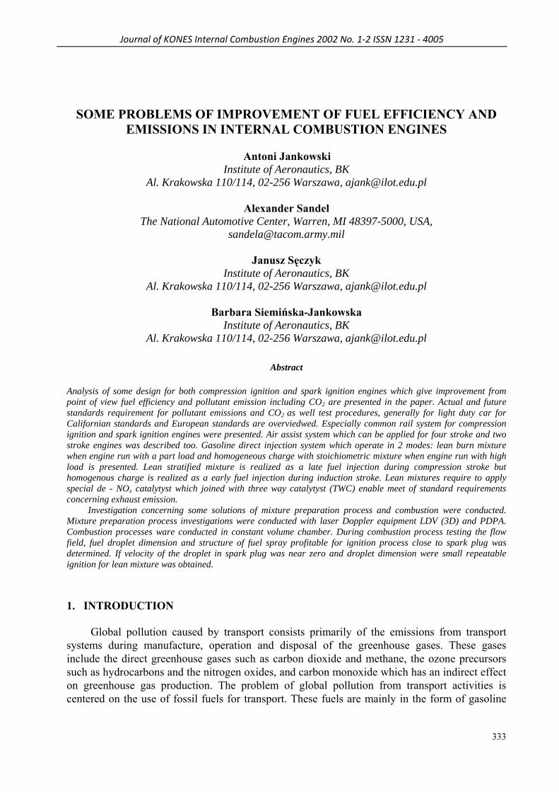
above-average emission control level was achieved primarily by using clean fuels, e.g. methanol and ethanol.
0.125
3.4
0.4
0.08 0.0150.075
3.4
0.20.08 0.0150.04
1.7
0.20.04 0.008
NMOG CO NOx PM ALD0
1
2
3
4 TLEV LEV ULEV
g/mile
0.25
3.4
0.4
0.08 0.0150.125
3.4
0.20.08 0.0150.075
1.7
0.20.04 0.008
NMOG CO NOx PM ALD0
1
2
3
4 TLEV LEV ULEV
g/mile
Fig. 1. USA California emissions limits for low emission vehicles categories (50 000 miles)
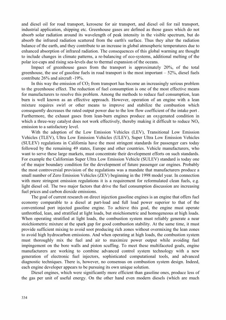
Fig. 2. USA California emissions limits for low
emission vehicles categories (50 000 miles) for flexible and dual fuelled
The use of energy sources that are no longer based on hydrocarbons, e.g. electrical energy,
hydrogen is also as these fuels will allow zero emissions of HC, CO, CO2, NOx. According to the pollutant quantities emitted and to the introduction time term, these vehicles are classified:
0.156
4.2
0.6
0.08 0.0180.09
4.2
0.3
0.08 0.0180.056
2.1
0.3
0.04 0.011
NMOG CO NOx PM ALD0
1
2
3
4
TLEV LEV ULEV
g/mile
0.31
4.2
0.6
0.08 0.0180.156
4.2
0.3
0.08 0.0180.09
2.1
0.3
0.04 0.011
NMOG CO NOx PM ALD0
1
2
3
4
TLEV LEV ULEV
g/mile
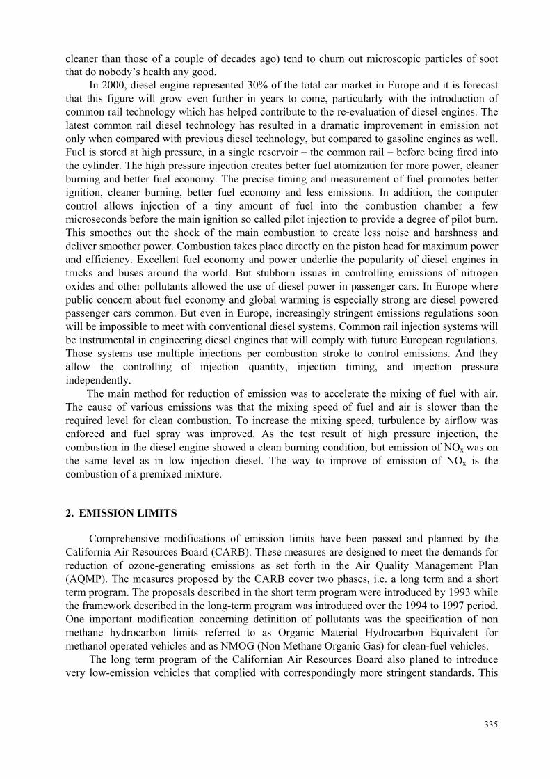
Fig. 3. USA California emissions limits for low emission vehicles categories (100 000 miles)
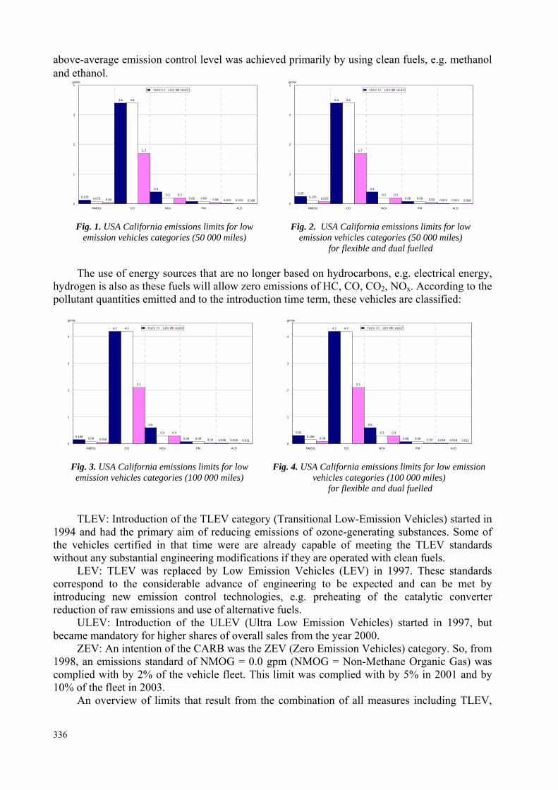
Fig. 4. USA California emissions limits for low emission
vehicles categories (100 000 miles) for flexible and dual fuelled
TLEV: Introduction of the TLEV category (Transitional Low-Emission Vehicles) started in 1994 and had the primary aim of reducing emissions of ozone-generating substances. Some of the vehicles certified in that time were are already capable of meeting the TLEV standards without any substantial engineering modifications if they are operated with clean fuels.
LEV: TLEV was replaced by Low Emission Vehicles (LEV) in 1997. These standards correspond to the considerable advance of engineering to be expected and can be met by introducing new emission control technologies, e.g. preheating of the catalytic converter reduction of raw emissions and use of alternative fuels.
ULEV: Introduction of the ULEV (Ultra Low Emission Vehicles) started in 1997, but became mandatory for higher shares of overall sales from the year 2000.
ZEV: An intention of the CARB was the ZEV (Zero Emission Vehicles) category. So, from 1998, an emissions standard of NMOG = 0.0 gpm (NMOG = Non-Methane Organic Gas) was complied with by 2% of the vehicle fleet. This limit was complied with by 5% in 2001 and by 10% of the fleet in 2003.
An overview of limits that result from the combination of all measures including TLEV,
336
LEV, ULEV and ZEV is shown in Fig. 1, 2, 3 and 4. 2.3
0.2 0.15
0.640.56 0.5
0.05
CO HC NOx CO HC NOx PM0
0.5
1
1.5
2
g/km
SPARK IGNITION COMPRESSION IGNITION
1
0.1 0.08
0.5
0.30.25
0.025
CO HC NOx CO HC NOx PM0
0.2
0.4
0.6
0.8
1g/km
SPARK IGNITION COMPRESSION IGNITION
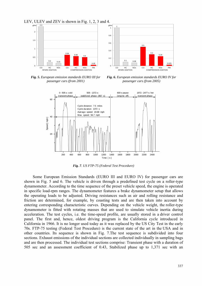
Fig. 5. European emission standards EURO III for passenger cars (from 2001)
Fig. 6. European emission standards EURO IV for
passenger cars (from 2005)
200 400 600 800 1000 1200 1400 1600 1800 2000 2200 2400
20
40
60
1972 - 2477 s: hottransient phase
600 s pause(engine off)
0 - 505 s: coldtransient phase
Cycle distance: 7.5 milesCycle duration: 1372 sAverage speed: 19.68 mphMax. speed: 56.7 mph
Time [ s ]
Spee
d [ m
ph ]
505 - 1372 s: stabilized phase (867 s)
Fig. 7. US FTP-75 (Federal Test Procedure)
Some European Emission Standards (EURO III and EURO IV) for passenger cars are
shown in Fig. 5 and 6. The vehicle is driven through a predefined test cycle on a roller-type dynamometer. According to the time sequence of the preset vehicle speed, the engine is operated in specific load-rpm ranges. The dynamometer features a brake dynamometer setup that allows the operating loads to be adjusted. Driving resistances such as air and rolling resistance and friction are determined, for example, by coasting tests and are then taken into account by entering corresponding characteristic curves. Depending on the vehicle weight, the roller-type dynamometer is fitted with rotating masses that are used to simulate vehicle inertia during acceleration. The test cycles, i.e. the time-speed profile, are usually stored in a driver control panel. The first and, hence, oldest driving program is the California cycle introduced in California in 1966. It is no longer used today as it was replaced by the US City Test in the early 70s. FTP-75 testing (Federal Test Procedure) is the current state of the art in the USA and in other countries. Its sequence is shown in Fig. 7.The test sequence is subdivided into four sections. Exhaust emissions of the individual sections are collected individually in sampling bags and are then processed. The individual test sections comprise: Transient phase with a duration of 505 sec and an assessment coefficient of 0.43, Stabilized phase up to 1,371 sec with an
337
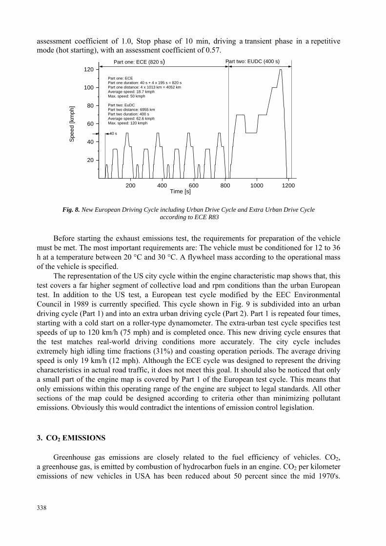
assessment coefficient of 1.0, Stop phase of 10 min, driving a transient phase in a repetitive mode (hot starting), with an assessment coefficient of 0.57.
200 400 600 800 1000 1200
20
40
60
80
100
120
Part one: ECE (820 s) Part two: EUDC (400 s)
Part one: ECE Part one duration: 40 s + 4 x 195 s = 820 s Part one distance: 4 x 10¹³ km = 4052 km Average speed: 18.7 kmph Max. speed: 50 kmph Part two: EuDC
Spe
ed [k
mph
]
Part two distance: 6955 km Part two duration: 400 s Average speed: 62.6 kmph Max. speed: 120 kmph
40 s
Time [s]
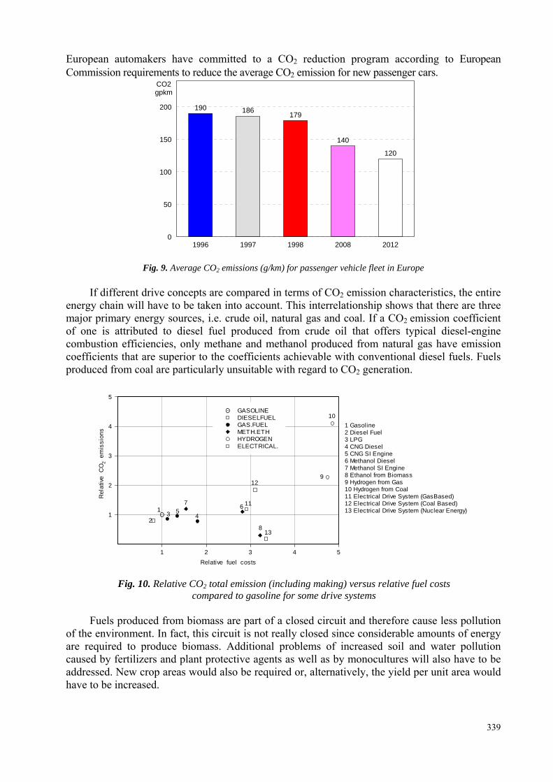
Fig. 8. New European Driving Cycle including Urban Drive Cycle and Extra Urban Drive Cycle according to ECE R83
Before starting the exhaust emissions test, the requirements for preparation of the vehicle must be met. The most important requirements are: The vehicle must be conditioned for 12 to 36 h at a temperature between 20 °C and 30 °C. A flywheel mass according to the operational mass of the vehicle is specified.
The representation of the US city cycle within the engine characteristic map shows that, this test covers a far higher segment of collective load and rpm conditions than the urban European test. In addition to the US test, a European test cycle modified by the EEC Environmental Council in 1989 is currently specified. This cycle shown in Fig. 9 is subdivided into an urban driving cycle (Part 1) and into an extra urban driving cycle (Part 2). Part 1 is repeated four times, starting with a cold start on a roller-type dynamometer. The extra-urban test cycle specifies test speeds of up to 120 km/h (75 mph) and is completed once. This new driving cycle ensures that the test matches real-world driving conditions more accurately. The city cycle includes extremely high idling time fractions (31%) and coasting operation periods. The average driving speed is only 19 km/h (12 mph). Although the ECE cycle was designed to represent the driving characteristics in actual road traffic, it does not meet this goal. It should also be noticed that only a small part of the engine map is covered by Part 1 of the European test cycle. This means that only emissions within this operating range of the engine are subject to legal standards. All other sections of the map could be designed according to criteria other than minimizing pollutant emissions. Obviously this would contradict the intentions of emission control legislation. 3. CO2 EMISSIONS
Greenhouse gas emissions are closely related to the fuel efficiency of vehicles. CO2,
a greenhouse gas, is emitted by combustion of hydrocarbon fuels in an engine. CO2 per kilometer emissions of new vehicles in USA has been reduced about 50 percent since the mid 1970's.
338
European automakers have committed to a CO2 reduction program according to European Commission requirements to reduce the average CO2 emission for new passenger cars.
190 186 179
140
120
1996 1997 1998 2008 20120
50
100
150
200
CO2gpkm
Fig. 9. Average CO2 emissions (g/km) for passenger vehicle fleet in Europe
If different drive concepts are compared in terms of CO2 emission characteristics, the entire energy chain will have to be taken into account. This interrelationship shows that there are three major primary energy sources, i.e. crude oil, natural gas and coal. If a CO2 emission coefficient of one is attributed to diesel fuel produced from crude oil that offers typical diesel-engine combustion efficiencies, only methane and methanol produced from natural gas have emission coefficients that are superior to the coefficients achievable with conventional diesel fuels. Fuels produced from coal are particularly unsuitable with regard to CO2 generation.
1 2 3 4 5
1
2
3
4
5
13
12
GASOLINE DIESELFUEL GAS.FUEL METH.ETH HYDROGEN ELECTRICAL.
1 Gasoline2 Diesel Fuel3 LPG4 CNG Diesel5 CNG SI Engine6 Methanol Diesel7 Methanol SI Engine8 Ethanol from Biomass9 Hydrogen from Gas10 Hydrogen from Coal11 Electrical Drive System (GasBased)12 Electrical Drive System (Coal Based)13 Electrical Drive System (Nuclear Energy)
11
8
64
10
9
753
1
2
Relative fuel costs
Rel
ativ
e C
O2
em
issi
ons
Fig. 10. Relative CO2 total emission (including making) versus relative fuel costs
compared to gasoline for some drive systems Fuels produced from biomass are part of a closed circuit and therefore cause less pollution
of the environment. In fact, this circuit is not really closed since considerable amounts of energy are required to produce biomass. Additional problems of increased soil and water pollution caused by fertilizers and plant protective agents as well as by monocultures will also have to be addressed. New crop areas would also be required or, alternatively, the yield per unit area would have to be increased.
339
If the emissions of conventional and alternative fuels are compared as an equivalent to CO2, in production, distribution and use we see that diesel oil from crude oil need the smallest emission CO2, emission of gasoline is 33 percent bigger, but methanol from crops is 120 percent bigger. If the problem of the greenhouse effect becomes more acute in the future - and there is nothing to indicate that this will not be the case - and if the problems that are invariably linked to more widespread use of nuclear energy are taken into account, only two alternatives remain in addition to cutting down energy use drastically. One alternative is to produce fuels from biomass, which means that the abovementioned problems will have to be overcome, and the other is to use solar energy for the production of hydrogen and of electrical energy.
Apart from technological and environmental requirements, the applicability of alternative fuel concepts is also subject to cost constraints. Figure 10 shows the relative CO2 emissions in terms of the relative fuel costs. Those alternatives that may contribute to reducing CO2 emissions significantly still entail costs today that amount to three to five times the price of gasoline. Alternative No. 13 shown in Fig. 10 should be considered as being fairly critical in terms of environmental compatibility. 4. SOME WAYS OF EMISSION IMPROVEMENT
The efficiency of an internal combustion engine and, hence, its specific fuel consumption
are largely dependent on the process characteristics of each cycle. Because of the internal combustion process in the engine cannot really be described accurately by computation, experimental comparison processes and descriptions of part systems are required. These comparison processes allow basic statements to be made, e.g. on the effect that the air fuel ratio or the compression ratio has influence on efficiency. Pollutant emissions and fuel consumption of both spark ignition and diesel engines may be reduced in a number of ways. But three basic approaches are commonly used.
Design parameters, e.g. cylinder head and combustion chamber design, including spark plug or glow plug position, design of injection system, injector position, number of valves, valve gear layout, variable valve timing, displacement (swept volume), bore-to-stroke ratio, compression ratio, inlet and exhaust port shape. Four or five-valve engines allow the spark plug to be positioned centrally. A compact combustion chamber with a central spark plug position that allows combustion time to be kept as short as possible thanks to short combustion paths and increased charge movement has a positive effect on HC emissions. Combustion noise constraints, however, tend to limit the speed of flame.
Operational parameters. They include e.g. engine management, mixture formation and mixture control, ignition timing, injection duration and injection timing, valve timing, internal exhaust recirculation based on modified engine timing, external exhaust recirculation, introduction of a latent heat accumulator to utilize engine, fuel supply cut-off in overrunning mode.
Exhaust gas aftertreatment using catalytic converter systems (including heated catalytic converters), secondary air injection, insulation of exhaust manifold and exhaust system, thermal reactors, filters (traps) or particulate retention systems.
Emission characteristics are influenced heavily by transient operating conditions and the operating period at which the engine has not yet reached its operating temperature. When running the stipulated test cycles, the initial 60 to 80 seconds have a decisive effect on whether the emission standards will be complied with. Cold intake pipes and combustion chamber walls, the higher frictional power to be overcome and a catalytic converter that has not yet reached its operating temperature are some of the factors that contribute to sharply increased emissions, particularly of HC and CO. This is where particular demands are placed on mixture formation and exhaust aftertreatment systems. At the same time, mixture formation under transient operating conditions is subject to additional requirements. Very rapidly changing operational
340
parameters action require an exactly timed correlation of parameters such as fuel quantity and ignition timing. External mixture preparation or mixture formation is the standard process used for spark ignition engines. Internal mixture preparation, however, is desirable with regard to fuel consumption as this represents a considerable fuel economy potential of approx. 20% at part throttle. The improved suitability for leaner engine settings that is a result of improved ignition and combustion conditions, however, prevents HC emissions from increasing. This is a vital feature of lean-burn engines. Extremely high combustion ratios cannot be achieved in the full-load range, however, since the knock limit prevents ignition timing from being matched to efficiency in an optimum manner.
In addition to extending the operating range with regard to the air/fuel ratio, lean-burn operation also provides considerable fuel savings, a fact that in turn reduces CO2 emissions. The exhaust temperature reduction achieved as the compression ratio is raised may, however, have a detrimental impact on the light-off performance of the catalytic converter in the warming-up phase. Retarded ignition timing may offset this drawback. The maximum NOx concentrations increase along with the compression ratio and are shifted towards higher excess air ratios at higher compression ratios. This is explained by the higher temperature level. 5. COMMON RAIL SYSTEMS
High speed DI diesel engine combines extremely high fuel economy (45 miles per gallon
highway and 37 miles per gallon city) and very good performance. The high speed DI diesel design contrasts with the widely used in direct injection diesel engine, which has a small secondary chamber in the cylinder head connected to the main combustion chamber via a throat. IDI diesels use these prechamber or swirl chambers to start off the combustion cycle and enhance fuel air mixing. As combustion proceeds from the swirl or prechamber, there are throttle and heat losses, which are the major reasons for the lower efficiency compared to DI. The throttle or flow losses are generated, because gases are forced from the swirl or prechamber through small bores, which are necessary to improve the fuel air mixture formation. An IDI unit provides a good precondition for high heat transfer to the surrounding walls, which results in heat losses. The breakthrough for engines was a fuel injection system that provides enough injection pressure to get the particulate emissions down as well, especially at a retarded injection timing, which is required to achieve low nitrous oxide emissions. A wide speed range, generally 1000 to 4000 rpm, is required for passenger car operation. It is very difficult, however, for a high speed DI diesel to have good fuel air mixture formation characteristics over a large speed range.
Increasingly stringent emissions regulations mean that high speed direct injection (HSDI) car engines will have to use new fuelling technologies in particular the use of far higher fuel injection pressures. Common Rail Direct Injection of diesel means direct injection of the fuel into the cylinders of a diesel engine via a single common line. Whereas ordinary diesel direct fuel-injection systems have to build up pressure a new for each and every injection cycle, the new common rail (line) engines maintain constant pressure regardless of the injection sequence. This pressure then remains permanently available throughout the fuel line. The engine's electronic timing regulates injection pressure according to engine speed and load. The electronic control unit modifies injection pressure precisely and as needed, based on data obtained from sensors on the cam- and crankshafts. In other words, compression and injection occur independently of each other. This technique allows fuel to be injected as needed, saving fuel and lowering emissions. Common rail injection systems is instrumental in engineering diesel engines that will comply with future European regulations. Those systems use multiple injections per combustion stroke to control emissions. The common rail technology is upgrading to comply with Europe’s upcoming EURO 4 emissions regulations. The efforts include increasing the number of injections per combustion stroke to five, from the present two, and raising the
341
maximum pressure to 180 MPa, from the present 135 MPa. It also is taking a close look at the possibility of adopting piezoelectric actuators for the injectors. Common rail systems permit higher specific output, better fuel consumption, much reduced noise, and generally improved characteristics. Specific power and torque are increased by approximately 40 percent compared with e.g. current IDI diesels, while specific fuel consumption and therefore carbon dioxide emissions is 30 percent better. The main advantage of a common rail system is that there is no relationship between engine speed and injector pressure. In addition, high speed engines offer reduced time for fuel air mixture formation.
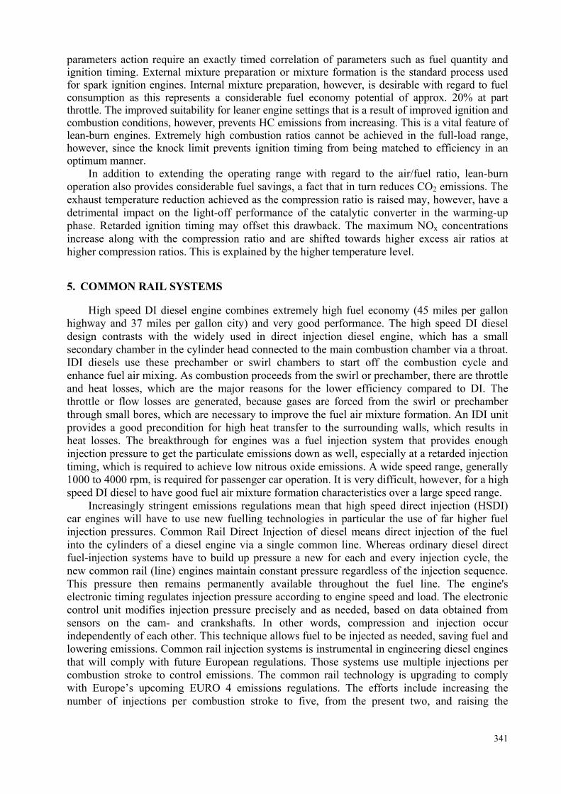
Fig. 11. Diagrammatic schema of common rail injection system for Diesel engines
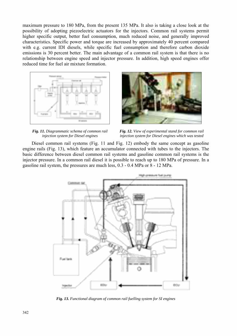
Fig. 12. View of experimental stand for common rail injection system for Diesel engines which was tested
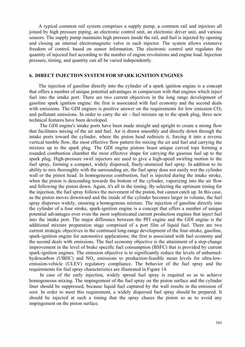
Diesel common rail systems (Fig. 11 and Fig. 12) embody the same concept as gasoline engine rails (Fig. 13), which feature an accumulator connected with tubes to the injectors. The basic difference between diesel common rail systems and gasoline common rail systems is the injector pressure. In a common rail diesel it is possible to reach up to 180 MPa of pressure. In a gasoline rail system, the pressures are much less, 0.3 - 0.4 MPa or 8 - 12 MPa.
Fig. 13. Functional diagram of common rail fuelling system for SI engines
342
A typical common rail system comprises a supply pump, a common rail and injectors all joined by high pressure piping, an electronic control unit, an electronic driver unit, and various sensors. The supply pump maintains high pressure inside the rail, and fuel is injected by opening and closing an internal electromagnetic valve in each injector. The system allows extensive freedom of control, based on sensor information. The electronic control unit regulates the quantity of injected fuel according to the number of engine revolutions and engine load. Injection pressure, timing, and quantity can all be varied independently.
6. DIRECT INJECTION SYSTEM FOR SPARK IGNITION ENGINES The injection of gasoline directly into the cylinder of a spark ignition engine is a concept
that offers a number of unique potential advantages in comparison with that engines which inject fuel into the intake port. There are two current objectives in the long range development of gasoline spark ignition engine: the first is associated with fuel economy and the second deals with emissions. The GDI engines is positive answer on the requirements for low emission CO2 and pollutant emissions. In order to carry the air - fuel mixture up to the spark plug, three new technical features have been developed.
The GDI engine's intake ports have been made straight and upright to create a strong flow that facilitates mixing of the air and fuel. Air is drawn smoothly and directly down through the intake ports toward the cylinder, where the piston head redirects it, forcing it into a reverse vertical tumble flow, the most effective flow pattern for mixing the air and fuel and carrying the mixture up to the spark plug. The GDI engine pistons boast unique curved tops forming a rounded combustion chamber the most effective shape for carrying the gaseous fuel up to the spark plug. High-pressure swirl injectors are used to give a high-speed swirling motion to the fuel spray, forming a compact, widely dispersed, finely-atomized fuel spray. In addition to its ability to mix thoroughly with the surrounding air, the fuel spray does not easily wet the cylinder wall or the piston head. In homogeneous combustion, fuel is injected during the intake stroke, when the piston is descending towards the bottom of the cylinder, vaporizing into the air flow and following the piston down. Again, it's all in the timing. By selecting the optimum timing for the injection, the fuel spray follows the movement of the piston, but cannot catch up. In this case, as the piston moves downward and the inside of the cylinder becomes larger in volume, the fuel spray disperses widely, ensuring a homogenous mixture. The injection of gasoline directly into the cylinder of a four stroke, spark-ignition engine is a concept that offers a number of unique potential advantages over even the most sophisticated current production engines that inject fuel into the intake port. The major difference between the PFI engine and the GDI engine is the additional mixture preparation stage comprised of a port film of liquid fuel. There are two current strategic objectives in the continued long-range development of the four-stroke, gasoline, spark-ignition engine for automotive applications; the first is associated with fuel economy and the second deals with emissions. The fuel economy objective is the attainment of a step-change improvement in the level of brake specific fuel consumption (BSFC) that is provided by current spark-ignition engines. The emission objective is to significantly reduce the levels of unburned-hydrocarbon (UBHC) and NOx emissions to production-feasible mean levels for ultra-low-emission-vehicle (ULEV) regulatory compliance. The behavior of the fuel spray and the requirements for fuel spray characteristics are illustrated in Figure 14.
In case of the early injection, widely spread fuel spray is required so as to achieve homogeneous mixing. The impingement of the fuel spray on the piston surface and the cylinder liner should be suppressed, because liquid fuel captured by the wall results in the emission of soot. In order to meet this requirement, a widely dispersed fuel spray should be prepared. It should be injected at such a timing that the spray chases the piston so as to avoid any impingement on the piston surface.
343
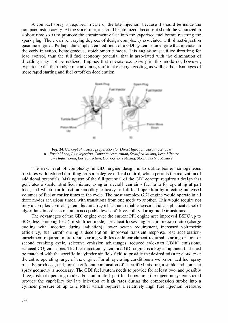
A compact spray is required in case of the late injection, because it should be inside the compact piston cavity. At the same time, it should be atomized, because it should be vaporized in a short time so as to promote the entrainment of air into the vaporized fuel before reaching the spark plug. There can be varying degrees of design complexity associated with direct-injection gasoline engines. Perhaps the simplest embodiment of a GDI system is an engine that operates in the early-injection, homogeneous, stoichiometric mode. This engine must utilize throttling for load control, thus the full fuel economy potential that is associated with the elimination of throttling may not be realized. Engines that operate exclusively in this mode do, however, experience the thermodynamic advantages of intake charge cooling, as well as the advantages of more rapid starting and fuel cutoff on deceleration.
Fig. 14. Concept of mixture preparation for Direct Injection Gasoline Engine a – Partial Load, Late Injection, Compact Atomization, Stratified Mixing, Lean Mixture
b – Higher Load, Early Injection, Homogenous Mixing, Stoichiometric Mixture The next level of complexity in GDI engine design is to utilize leaner homogeneous
mixtures with reduced throttling for some degree of load control, which permits the realization of additional potentials. Making use of the full potential of the GDI concept requires a design that generates a stable, stratified mixture using an overall lean air - fuel ratio for operating at part load, and which can transition smoothly to heavy or full load operation by injecting increased volumes of fuel at earlier times in the cycle. The most complex GDI engine would operate in all three modes at various times, with transitions from one mode to another. This would require not only a complex control system, but an array of fast and reliable sensors and a sophisticated set of algorithms in order to maintain acceptable levels of drive-ability during mode transitions.
The advantages of the GDI engine over the current PFI engine are: improved BSFC up to 30%, less pumping loss (for stratified mode), less heat losses, higher compression ratio (charge cooling with injection during induction), lower octane requirement, increased volumetric efficiency, fuel cutoff during a deceleration, improved transient response, less acceleration-enrichment required, more rapid starting with less cold enrichment required, starting on first or second cranking cycle, selective emission advantages, reduced cold-start UBHC emissions, reduced CO2 emissions. The fuel injection system in a GDI engine is a key component that must be matched with the specific in cylinder air flow field to provide the desired mixture cloud over the entire operating range of the engine. For all operating conditions a well-atomized fuel spray must be produced, and, for the efficient combustion of a stratified mixture, a stable and compact spray geometry is necessary. The GDI fuel system needs to provide for at least two, and possibly three, distinct operating modes. For unthrottled, part-load operation, the injection system should provide the capability for late injection at high rates during the compression stroke into a cylinder pressure of up to 2 MPa, which requires a relatively high fuel injection pressure.
344
The injection pressure is also very important for obtaining both effective spray atomization and the required level of spray penetration. A higher fuel injection pressure is effective in reducing the mean droplet diameter of the spray approximately as the inverse square root of the pressure differential, whereas the use of a lower pressure generally reduces the pump parasitic load and injector noise, and increases the reliability of the fuel pump system. The use of a very high fuel injection pressure, such as 20 MPa, will enhance the atomization but will most likely generate an over penetrating spray, resulting in fuel wall wetting. A constant fuel line pressure is utilized in a common-rail system for most of the current GDI applications; however, a strategy using a variable fuel injection pressure does offer an alternative method of obtaining the required flow range while reducing the dynamic-range requirements of the injector itself and for meeting differing fuel spray requirements corresponding to a range of engine loads.
The GDI engine can achieve important fuel economy benefits because of the possible operation with a higher knock-limited compression ratio, but this tends to elevate the NOx emission levels. As a result, the NOx level of the GDI engine without EGR is similar to that for the PFI engine, even though some GDI engines can operate at an air - fuel ratios leaner than 50 at low load. For an engine such as the GDI that operates with lean or even ultra-lean mixtures, a conventional three-way catalyst cannot be used to remove NOx, therefore other techniques for in-cylinder NOx reduction or exhaust aftertreatment are necessary. There is a consensus that NOx reduction aftertreatment for lean burn engines is a challenging task, especially in view of the lower exhaust gas temperature. Furthermore, part load, lean operation of the GDI engine is quite frequent, and contributes about half of the NOx emissions for the total test.
7. AIR ASSIST INJECTION SYSTEM Gasoline direct injection technology is rapidly evolving. At present, there does not exist
a dominant combustion system, however many believe that the ultimate system will be spray or jet guided. These combustion systems rely on an ignitable mixture being promoted directly from the injection source to the spark plug gap location. Small droplet sizes, coupled with low penetration rates and diffuse sprays, characteristic of air assisted direct injection systems, are ideally suited to these spray guided combustion systems. The air assist system may be applied both in two stroke and four stroke combustion engines. The ability of the air assisted system to function with the spark plug directly in the injected spray without plug fouling problems is testament to the quality of fuel preparation enabled by the dual fluid injection process.
Direct injection gasoline engine technology is becoming increasingly popular due to the potential to reduce fuel consumption with little compromise to what the automotive gasoline engine offers today in terms of power density and cost. The system of choice is still unclear, with investigations continuing on both wall or charge motion guided systems as well as jet or spray guided systems. The spray guided combustion system is the one with perhaps the most potential for a direct injected automotive gasoline engine. The spray guided combustion system directs the fuel spray directly to the spark plug gap location. For wall guided systems, there is transportation of the injected fuel to the plug gap by means of interaction with the piston bowl and/or the air motion within the cylinder. The result of this is longer preparation time of the fuel, which is currently required for single fluid injectors. The well prepared finely atomized fuel spray produced by the air assisted fuel system does not require the increased preparation time and so provides the necessary characteristics for the successful implementation of the spray guided combustion system. Indeed, the major problems associated with single fluid implementation of spray guided combustion systems, that is spark plug durability and steep air/fuel ratio gradients leading to poor robustness, are addressed due to the air assisted direct injection fuel spray qualities.
345
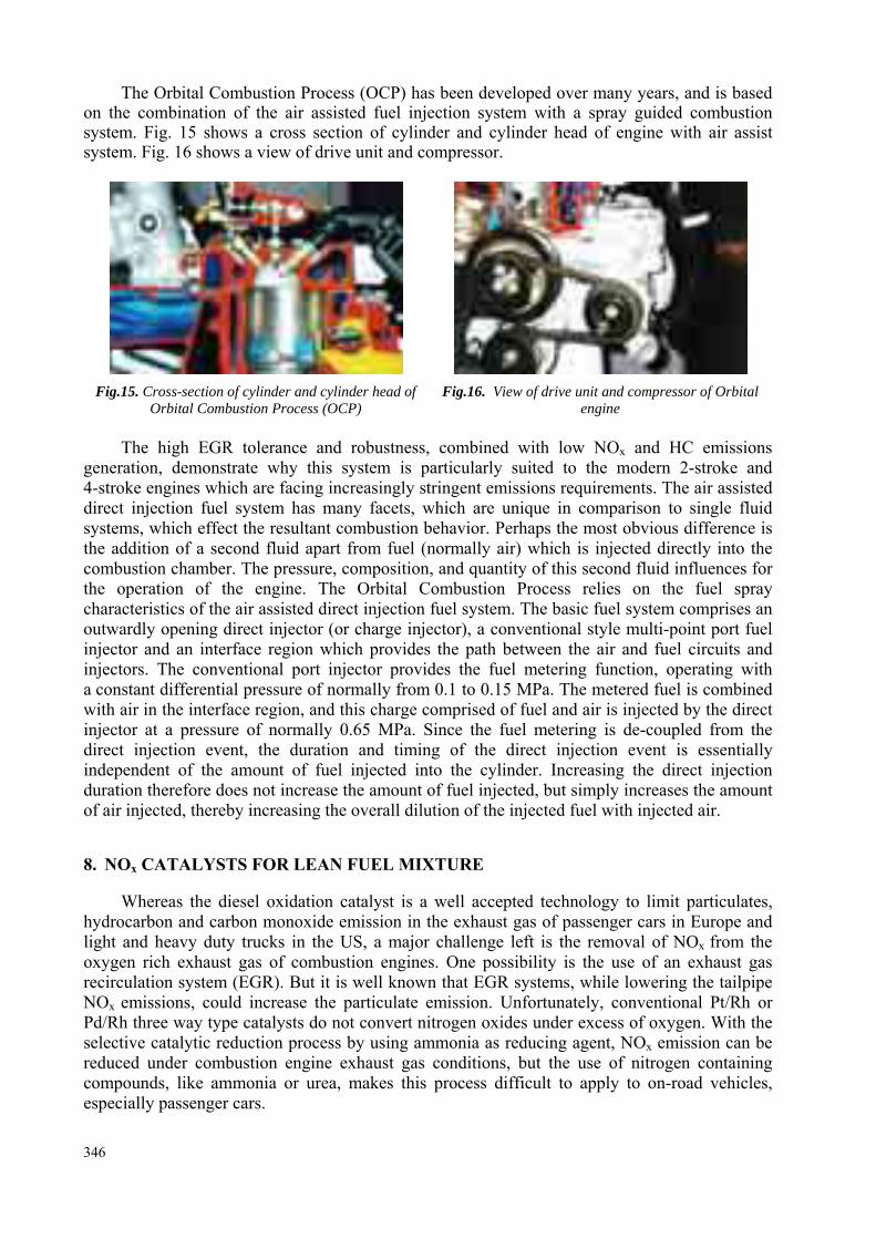
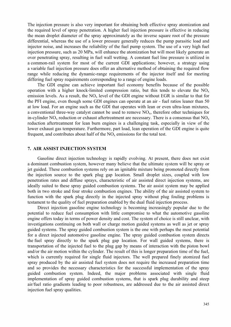
The Orbital Combustion Process (OCP) has been developed over many years, and is based on the combination of the air assisted fuel injection system with a spray guided combustion system. Fig. 15 shows a cross section of cylinder and cylinder head of engine with air assist system. Fig. 16 shows a view of drive unit and compressor.
Fig.15. Cross-section of cylinder and cylinder head of
Orbital Combustion Process (OCP) Fig.16. View of drive unit and compressor of Orbital
engine The high EGR tolerance and robustness, combined with low NOx and HC emissions
generation, demonstrate why this system is particularly suited to the modern 2-stroke and 4-stroke engines which are facing increasingly stringent emissions requirements. The air assisted direct injection fuel system has many facets, which are unique in comparison to single fluid systems, which effect the resultant combustion behavior. Perhaps the most obvious difference is the addition of a second fluid apart from fuel (normally air) which is injected directly into the combustion chamber. The pressure, composition, and quantity of this second fluid influences for the operation of the engine. The Orbital Combustion Process relies on the fuel spray characteristics of the air assisted direct injection fuel system. The basic fuel system comprises an outwardly opening direct injector (or charge injector), a conventional style multi-point port fuel injector and an interface region which provides the path between the air and fuel circuits and injectors. The conventional port injector provides the fuel metering function, operating with a constant differential pressure of normally from 0.1 to 0.15 MPa. The metered fuel is combined with air in the interface region, and this charge comprised of fuel and air is injected by the direct injector at a pressure of normally 0.65 MPa. Since the fuel metering is de-coupled from the direct injection event, the duration and timing of the direct injection event is essentially independent of the amount of fuel injected into the cylinder. Increasing the direct injection duration therefore does not increase the amount of fuel injected, but simply increases the amount of air injected, thereby increasing the overall dilution of the injected fuel with injected air. 8. NOx CATALYSTS FOR LEAN FUEL MIXTURE
Whereas the diesel oxidation catalyst is a well accepted technology to limit particulates,
hydrocarbon and carbon monoxide emission in the exhaust gas of passenger cars in Europe and light and heavy duty trucks in the US, a major challenge left is the removal of NOx from the oxygen rich exhaust gas of combustion engines. One possibility is the use of an exhaust gas recirculation system (EGR). But it is well known that EGR systems, while lowering the tailpipe NOx emissions, could increase the particulate emission. Unfortunately, conventional Pt/Rh or Pd/Rh three way type catalysts do not convert nitrogen oxides under excess of oxygen. With the selective catalytic reduction process by using ammonia as reducing agent, NOx emission can be reduced under combustion engine exhaust gas conditions, but the use of nitrogen containing compounds, like ammonia or urea, makes this process difficult to apply to on-road vehicles, especially passenger cars.
346
The parameters deal with the catalyst, the engine and the fuel characteristics influence on catalyst efficiency and durability. Some of the most important system parameters for this application are the effects of the catalytic ingredients, the exhaust gas NOx, HC, O2, CO, SO2 and H2O content, the exhaust gas temperature, the exhaust gas pressure and the space flow fields. Hydrocarbons are the most effective internal reducing agents to achieve NOx conversion. The NOx conversion behavior seems to be directly related to the conversion of hydrocarbons. The hydrocarbon component has a significant influence on the NOx conversion. The HC efficiency for NOx decreases in the order aromatics > olefins > paraffins.
Nitrogen monoxide is thermodynamically unstable relative to N2 and O2 at typical combustion exhaust gas temperatures.
The Table 1 shows the values of the equilibrium constant K calculated for various possible reactions of NO in the exhaust gas according to the equation:
Go(T) = -RT InK(T) where:
Go = Gibbs-Standard-Free-Energy at 700 [K] [J mol-1] R = Gas constant [JK-1 mol-1] T = Gas temperature [K]
Table 1. Equilibrium constant K calculated for different NO reactions
Equilibrium constant K 700 [K]
NO = 1/2 N2 + 1/2 O2 1.3 × 10⁶ NO + 1/2 O2 = NO2 2.11 CO + NO = CO2 + 1/2 N2 5.6 × 10²² CH4 + 4 NO = CO2 + 2 H2O + 2 N2 2.2 × 1084 2 NO + 2 H2 = 2 H2O + N2 6.0 × 10²¹ H2 + 2 NO = H2O + N2O 8.5 × 10⁸ 3/2 H2 + NO = H2O + NH3 5.5 × 10¹⁵ 2 NO = N2O + 1/2 O2 12.7 NO2 = 1/2 N2 + O2 5.9 × 10⁵
K value > 1 means the reactions are thermodynamically possible at the relevant
temperature. From the data it can be concluded that not only the direct decomposition, but various other reactions are possible to a high conversion degree under reaction conditions, typical for the exhaust gas stream of a combustion engine.
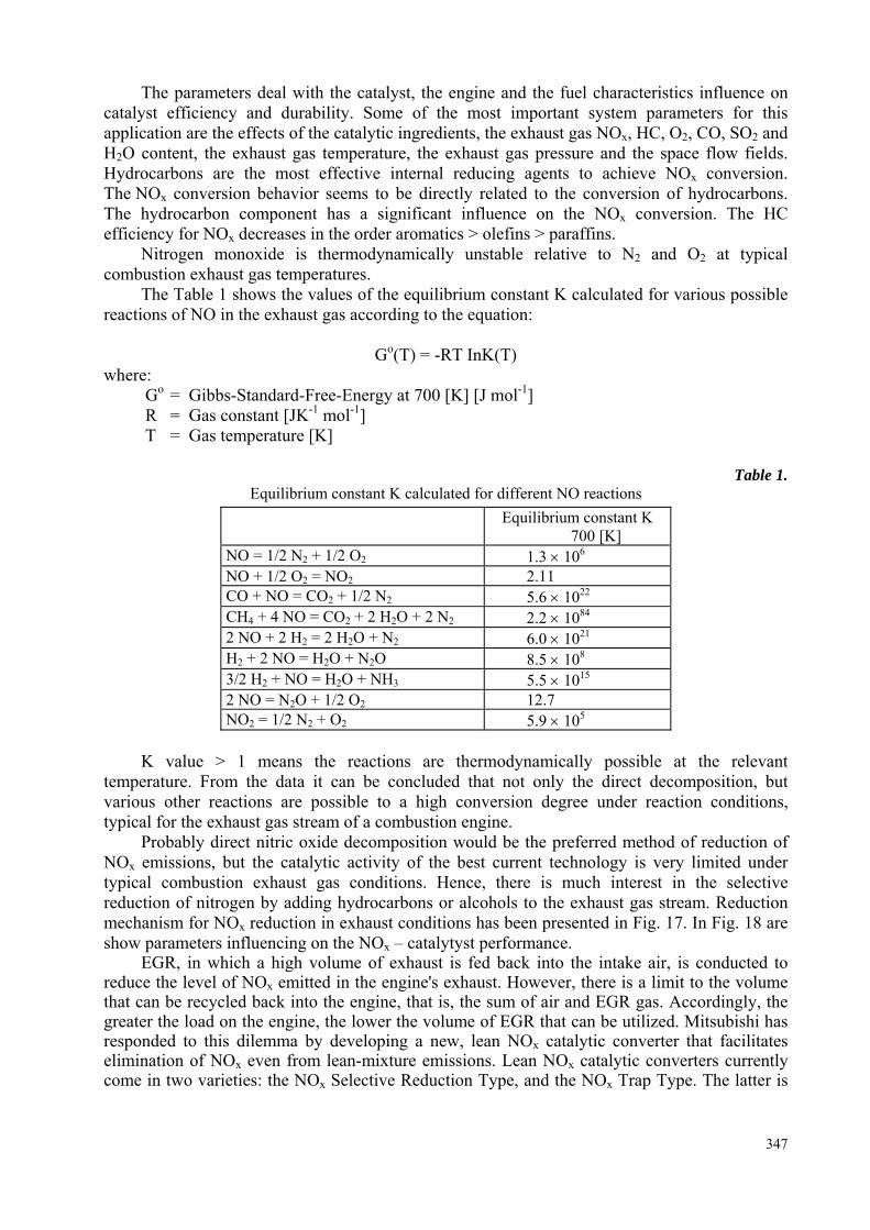
Probably direct nitric oxide decomposition would be the preferred method of reduction of NOx emissions, but the catalytic activity of the best current technology is very limited under typical combustion exhaust gas conditions. Hence, there is much interest in the selective reduction of nitrogen by adding hydrocarbons or alcohols to the exhaust gas stream. Reduction mechanism for NOx reduction in exhaust conditions has been presented in Fig. 17. In Fig. 18 are show parameters influencing on the NOx – catalytyst performance.
EGR, in which a high volume of exhaust is fed back into the intake air, is conducted to reduce the level of NOx emitted in the engine's exhaust. However, there is a limit to the volume that can be recycled back into the engine, that is, the sum of air and EGR gas. Accordingly, the greater the load on the engine, the lower the volume of EGR that can be utilized. Mitsubishi has responded to this dilemma by developing a new, lean NOx catalytic converter that facilitates elimination of NOx even from lean-mixture emissions. Lean NOx catalytic converters currently come in two varieties: the NOx Selective Reduction Type, and the NOx Trap Type. The latter is
347
highly effective when new, but their viability is considerably reduced when gasoline with a high sulphur content is used. Long term use of this type of NOx catalytic converter in Europe, where the sulphur content of gasoline is higher would result in almost total loss in effectiveness. In contrast, the NOx Selective Reduction Type catalysts, while less effective in the early stages, are hardly damaged by sulphur.
Test Cycle
NO Catalystx
Active Component
Space Velocity
Active Components
Substrate Characterestics
Ehaust Gas Pressure
Exhaust Gas Temeprature
Exhaust Gas Composition
Fig.17. Reaction mechanism for NOx reduction in lean mixture
Fig. 18. Parameters influencing on the NOx catalyst performance
Appropriate type of Lean NOx catalyst for the GDI engine depends on the sulphur content
and of the region in which the engine will be used. Type catalysts for using in areas where the sulphur content in gasoline is high NOx Trap Type catalysts for using in areas where the sulphur content is low. For example, to eliminate HC and NOx during stoichiometric operation, a three way catalyst is also added downstream from the NOx catalytic converter. 9. EXPERIMENTS
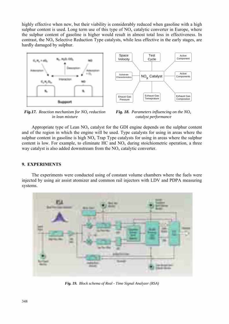
The experiments were conducted using of constant volume chambers where the fuels were
injected by using air assist atomizer and common rail injectors with LDV and PDPA measuring systems.
Fig. 19. Block schema of Real - Time Signal Analyzer (RSA)
348
The measurements of spray spectrum were performed in different cross section of fuel sprays. The injectors and atomizers were specially modified for that purpose, so that a single jet fuel entered into measuring chamber. In case of common rail injector the flow from only one hole was present but remaining orifices were joined to a separate collecting vessel.
The measurement of drop size and velocity is based on the observation of the light scattered by drops passing through the crossover region of two intersecting laser beams. In practice, a single laser beam is split into two coherent beams of equal intensity and parallel polarization, which are made to cross. Drops passing through the intersection of the two beams scatter light that produces information from which the drop velocity v is calculated as
v2sin( / 2)
Dfλ=
Θ
where λ is the wavelength of laser light, fD the Doppler frequency, and θ/2 the laser beam intersection half-angle.
Size information is contained in the relative modulation visibility (V) of the scattered signal. The term visibility was defined by Michelson as
max min
max min
V I II I
−=
+
where Imax and Imin are maximum and minimum values of fringe modulated signal
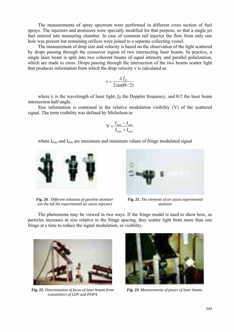
Fig. 20. Different solutions of gasoline atomizer (on the left the experimental air assist injector)
Fig. 21. The elements of air assist experimental atomizer
The phenomena may be viewed in two ways. If the fringe model is used to show how, as
particles increases in size relative to the fringe spacing, they scatter light from more than one fringe at a time to reduce the signal modulation, or visibility.
Fig. 22. Determination of focus of laser beams from
transmitters of LDV and PDPA Fig. 23. Measurements of power of laser beams
349
A more rigorous description considers the superposition of the light scattered from each beam separately which then interferes. In the near-forward direction, and for particles much larger than the light wavelength, this scattered light may be described by Fraunhofer diffraction theory or more accurately, for spherical particles of arbitrary size, by the Lorenz-Mie theory. The relative overlap of the forward-scattered light intensities then determines the relative visibility of the scattered interference fringe pattern. For example, larger particles scatter light that is more narrowly distributed in the forward direction, hence producing less intensity overlap for a given beam intersection angle. Based on the scalar diffraction theory and the derivation of Farmer, the relationship between drop size and visibility can be expressed.
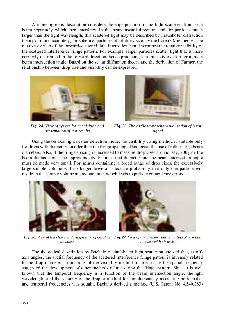
Fig. 24. View of system for acquisition and
presentation of test results Fig. 25. The osciloscope with visualization of burst
signal
Using the on-axis light scatter detection mode, the visibility sizing method is suitable only for drops with diameters smaller than the fringe spacing. This forces the use of rather large beam diameters. Also, if the fringe spacing is increased to measure drop sizes around, say, 200 μm, the beam diameter must be approximately 10 times that diameter and the beam intersection angle must be made very small. For sprays containing a broad range of drop sizes, the excessively large sample volume will no longer leave an adequate probability that only one particle will reside in the sample volume at any one time, which leads to particle coincidence errors.
Fig. 26. View of test chamber during testing of gasoline
atomizer Fig. 27. View of test chamber during testing of gasoline
atomizer with air assist
The theoretical description by Bachalo of dual-beam light scattering showed that, at off-axis angles, the spatial frequency of the scattered interference fringe pattern is inversely related to the drop diameter. Limitations of the visibility method for measuring the spatial frequency suggested the development of other methods of measuring the fringe pattern. Since it is well known that the temporal frequency is a function of the beam intersection angle, the light wavelength, and the velocity of the drop, a method for simultaneously measuring both spatial and temporal frequencies was sought. Bachalo derived a method (U.S. Patent No. 4,540,283)
350
using pairs of detectors at fixed spacing in the image of the interference or fringe pattern. The method has been developed into a Phase Doppler Particle Analyzer by Aerometric, Inc.
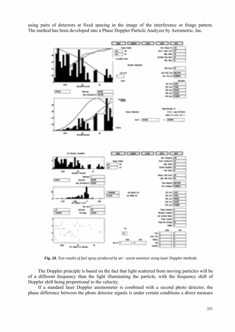
Fig. 28. Test results of fuel spray produced by air - assist atomizer using laser Doppler methods
The Doppler principle is based on the fact that light scattered from moving particles will be of a different frequency than the light illuminating the particle, with the frequency shift of Doppler shift being proportional to the velocity.
If a standard laser Doppler anemometer is combined with a second photo detector, the phase difference between the photo detector signals is under certain conditions a direct measure
351
of the particle size. A third photo detector is included to extend the dynamic range, and in two dimensional flows a color separator and fourth photo detector are added to allow two velocity directions to be measured. A fifth photo detector is needed for measurement of three dimensional flows.
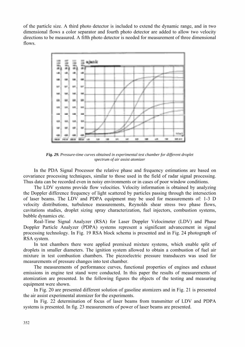
Fig. 29. Pressure-time curves obtained in experimental test chamber for different droplet spectrum of air assist atomizer
In the PDA Signal Processor the relative phase and frequency estimations are based on
covariance processing techniques, similar to those used in the field of radar signal processing. Thus data can be recorded even in noisy environments or in cases of poor window conditions.
The LDV systems provide flow velocities. Velocity information is obtained by analyzing the Doppler difference frequency of light scattered by particles passing through the intersection of laser beams. The LDV and PDPA equipment may be used for measurements of: 1-3 D velocity distributions, turbulence measurements, Reynolds shear stress two phase flows, cavitations studies, droplet sizing spray characterization, fuel injectors, combustion systems, bubble dynamics etc.
Real-Time Signal Analyzer (RSA) for Laser Doppler Velocimeter (LDV) and Phase Doppler Particle Analyzer (PDPA) systems represent a significant advancement in signal processing technology. In Fig. 19 RSA block schema is presented and in Fig. 24 photograph of RSA system.
In test chambers there were applied premixed mixture systems, which enable split of droplets in smaller diameters. The ignition system allowed to obtain a combustion of fuel air mixture in test combustion chambers. The piezoelectric pressure transducers was used for measurements of pressure changes into test chamber.
The measurements of performance curves, functional properties of engines and exhaust emissions in engine test stand were conducted. In this paper the results of measurements of atomization are presented. In the following figures the objects of the testing and measuring equipment were shown.
In Fig. 20 are presented different solution of gasoline atomizers and in Fig. 21 is presented the air assist experimental atomizer for the experiments.
In Fig. 22 determination of focus of laser beams from transmitter of LDV and PDPA systems is presented. In fig. 23 measurements of power of laser beams are presented.
352
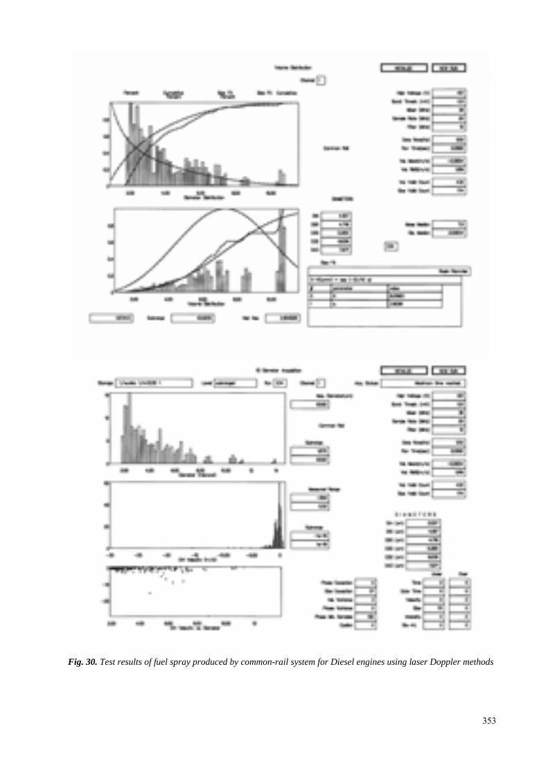
Fig. 30. Test results of fuel spray produced by common-rail system for Diesel engines using laser Doppler methods
353
In Fig. 24 are presented real time signal analyzer, block of detectors, computer with monitor and printer for acquisition and presentation test results. In the Fig. 25 the oscilloscope with visualization of burst signal are presented.
In Fig. 27 and in Fig. 28 view of test chamber during testing of conventional gasoline atomizer and air assist atomizer are presented respectively.
Results of measurements of fuel spray using laser Doppler methods are presented in Fig. 28. Measurement results concerning air assist atomizer are shown. There are mean diameters of spray, velocities spectrum and diameter versus velocity of droplets. The probability spectrum and diameter versus velocity of droplets. The probability distributions are presented too.
In Fig. 29 are presented time curves obtained in experimental test chamber for different droplet spectrum of air assist atomizer. These curves may be obtained if mixture ignition exists in combustion chamber. Mixture ignition appears when the Sauter Mean Diameter (SMD) of a droplets close the spark plug were smaller than 20 μm and velocity was close 0. In this experiment premixed mixture system and stratified lean burn system were applied. In Fig. 30 are presented results of measurements concerning one test of common rail system. There are diagram of mean diameters velocities of droplets. The probability disposition of droplet diameters are presented also. 10. CONCLUSIONS
Analysis conducted of different engines fueling system shows that common rail system is
the best solution for compression ignition engines as well for spark ignition engines. Common rail system applied in compression ignition engines gives high NOx emission and
therefore research and development works have the objective to low NOx emission. These works drive to apply premixed mixture systems for compression ignition engines.
Premixed mixture systems of mixture preparation are proper for compression ignition as well spark ignition engines.
Good results are obtained in experiment if applied of premixed mixture system in constant volume chamber.
To obtain repeatable ignition it need to seek the flow field in the field where droplet velocity is close to zero and the droplet have a small dimension.
The research conducted with air assist system in constant volume chamber proves that efficient ignition can be obtained if the Sauter Mean Diameter (SMD) of droplets was smaller than 20 μm.
Obtaining of a small SMD droplet diameters in electronically controlled injectors require elimination of big droplet in mixture causes the increase of SMD of droplets and increase of pollutant exhaust emission and even lack of ignition. REFERENCES [1] Arcoumanis, C., Gold, M. R., Whitelaw, J. H., and Xu, H. M., Local charge stratification in spark-
ignition engines, I.MechE. Seminar of Lean Bum Combustion Engines, S433, December 3-4,1996 [2] Bielaczyc, P., Merkisz J., Pielecha, J., Stan cieplny silnika spalinowego a emisja związków
toksycznych, Politechnika Poznańska, Poznań 2001 [3] Brogan M.S., Swallow D., Brisley R.J., Worth D., Yang K.C.: A New Approach to Meeting Future
European Emissions Standards with the Orbital Direct Injection Gasoline Engine. SAE 2000-01-2913
354
[4] Brzozowska, L., Brzozowski K., Wojciech, S., Computational Modelling of Car Pollutant Dispersion, Śląsk, Katowice 2001
[5] Cathcart, G. and Tubb, J., Application of Air Assisted Direct Fuel Injection to Pressure Charged Gasoline Engines, SAE Technical Paper, No. 2002-01-0705
[6] Cathcart, G. and Zavier, C., Fundamental Characteristics of an Air - Assisted Direct Injection Combustion System as Applied to 4 - Stroke Automotive Gasoline Engines, SAE Technical Paper, No. 2002-01-0256
[7] Hachisuka, I., Yoshida, T., Ueno H., Takahashi, N., Suda, A. and Sugiura, M., Improvement of NOx Storage - Reduction Catalyst, SAE Technical Paper, No. 2002-01-0732
[8] Harada, J., Tomita, T., Mizuno, H., Mashiki, Z., and Ito, Y., Development of a direct injection gasoline engine, SAE Technical Paper, No. 970540
[9] Herzog P.: The Ideal Rate of Injection for Swirl Supported Diesel Engines. IMechE Seminar on Diesel Fuel Injection Systems 10 - 11 October 1989
[10] Heywood J.B.: Internal Combustion Engine Fundamentals. McGraw-Hill, 1988 [11] Hoffman, J., Eberhardt, E., and Martin, J. K., Comparison between air-assisted and single-fluid
pressure atomizers for direct-injection Sl engines via spatial and temporal mass flux measurements, SAE Technical Paper, No. 970630
[12] Kari, G., Kemmler, R., and Bargende, M., Analysis of a direct injected gasoline engine, SAE Technical Paper, No. 970624
[13] Khan I.M., Greeves G., Wang C.H.T: Factors Affecting Smoke and Gaseous Emissions from Direct Injection Engines and a Method of Calculation. SAE 730169
[14] Kiyota, Y., Akishino, K. and Ando, H. : Combustion Control Technologies for Direct Injection SI Engines, FISITA96
[15] Kono, S., Study of the stratified charge and stable combustion in Dl gasoline engines, SAE Technical Paper, No. 950688
[16] Kruczyński, S. W., Właściwości katalizatora Ag/Al203-SiO2 do redukcji tlenków azotu weglowodorami w spalinach silnika o zapłonie samoczynnym. Zeszyty Naukowe Instytutu Pojazdów, Wydział Samochodów I Maszyn Roboczych, Politechnika Warszawska, 2(410/2001
[17] Lake, T. H., Sapsford, S. M., Stokes, J., and Jackson, N. S., Simulation and development experience of a stratified charge gasoline direct injection engine, SAE Technical Paper, No. 962014(1996)
[18] Nishizawa K., Momoshima S., Koga M., Tsuchida H., Yamamoto S.: Development of New Technologies Targeting Zero Emissions for Gasoline Engines. SAE Paper 2000-01-0551
[19] Parrish, S. and Farrel, P. V., Transient spray characteristics of a direct-injection spark-ignited fuel injector, SAE Technical Paper, N0.970629
[20] Pontoppidan, M., Gaviani, G., and Marelli, M., Direct fuel-injection - a study of injector requirements for different mixture preparation concepts, SAE Technical Paper, No. 970628
[21] Robart D., Breuer S., Reckers W., Kneer R.: Assessment of pulsed gasoline fuel sprays by means of qualitative laser based diagnostic methods. 10th International Symposium on Application of laser technique to Fluid Mechanics. Lisbon, 10 - 13 July 2001
[22] Seiffert, U., The automobile in the next century, FISITA Technical Paper. No. K0011 (1996) [23] Stone, R. C., Wyszynski, L. P. and Raine, R. R., Prediction of NO Emissions from Stratified
Charge Spark - Ignition Engines, SAE Technical Paper, No. 2002-01-1139 [24] Takagi, Y., The role of mixture formation in improving fuel economy and reducing emissions of
automotive S.I. engines, FISITA Technical Paper, No. P0109 1996 [25] Theis, J. I., Gobel, U., Kogel, M., Kreuzer, T. P., Lindner, D., Lox, E. and Ruwisch L.,
Phenomenological Studies on the Storage and Regeneration Process of NOx Storage Catalysts for Gasoline Lean Burn Applications, SAE Technical Paper, No. 2002-01-0757
[26] Theis, J. R., Li J. J., Ura, J. A. and Hurley, R. G., The Desulfation Characteristics of Lean NOx Traps, SAE Technical Paper, No. 2002-01-0733
355
[27] Tomoda, T., Sasaki, S., Sawada, D., Saito, A., and Sami, H., Development of direct injection gasoline engine - study of stratified mixture formation, SAE Technical Paper. No. 970539
[28] Tsujamura, K., Aoyagi, Y., Akagawa, H. and Takeda, Y., The Concept for Compression Ignition Engines Using Premixed Mixture, Proceedings of the Fifth International Symposium on Diagnostics and Modeling of Combustion in Internal Combustion Engine (COMODIA 2001), July 1-4, 2001, Nagoya
[29] Zhao F., Lai M.C., Harington D.L.: Automotive spark ignited direct - injection gasoline engines. Progress in Energy and Combustion Science, 25 437 - 562, 1999
356


![Fuel Consumption Improvement Study over combinations of ... · Fuel Consumption Improvement Study over combinations of technologies [Rev. 2] VOLPE vs. Autonomie (ANL) For DOT/VOLPE](https://img.pdfslide.us/doc/110x75/5e9295cf0ff4be1b8f586628/fuel-consumption-improvement-study-over-combinations-of-fuel-consumption-improvement.jpg)