Embed Size (px)
Citation preview
597
Some mass transfer effects on the wall jet
By HERBERT FOX AND MARTIN H. STEIGER Polytechnic Institute of Brooklyn
(Received 14 September 1962)
The wall jet with suction or injection is investigated; an analysis under conditions corresponding to similar flows is shown to reduce to an eigenvalue problem. Asymptotic solutions valid far from the surface are used to initiate the integra- tion and circumvent the usual iteration associated with the two-point boundary- value problem. Typical solutions for various rates of suction and injection are obtained. It is found that the skin friction decreases with increasing rate of suction. Representative thermal solutions are obtained for Prandtl and Lewis numbers equal to one, under the special condition that the surface temperature is equal to the ambient temperature or that the enthalpy varies monotonically from the surface value to the ambient value.
1. Introduction The term ‘wall jet’ has been introduced by Glauert (1956) to characterize
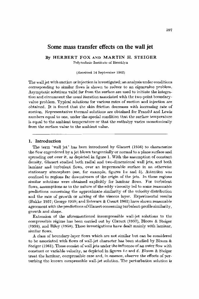
the flow engendered by a jet blown tangentially or normal to a plane surface and spreading out over it, as depicted in figure 1. With the assumption of constant density, Glauert studied both radial and two-dimensional wall jets, and both laminar and turbulent flows, over an impermeable surface in an otherwise stationary atmosphere (see, for example, figures l a and b). Attention was confined to regions far downstream of the origin of the jets. In these regions similar solutions were obtained explicitly for laminar flows. For turbulent flows, assumptions as to the nature of the eddy viscosity led to some reasonable predictions concerning the approximate similarity of the velocity distribution and the rate of growth or mixing of the viscous layer. Experimental results (Bakke 1957; George 1959; and Schwarz & Cosart 1961) have shown reasonable agreement with the predictions of Glauert concerning turbulent-profile similarity, growth and shape.
Extension of the aforementioned incompressible wall-jet solutions to the compressible regime has been carried out by Glauert (1957), Bloom & Steiger (1958), and Riley (1958). These investigations have dealt mainly with laminar, similar flows.
A class of boundary-layer flows which are not similar but can be considered to be associated with flows of wall-jet character has been studied by Bloom & Steiger (1961). These consist of wall jets under the influence of an outer flow with constant or variable velocity, ;ls depicted in figures 1 c and d. Bloom & Steiger treat the laminar, compressible case and, in essence, observe the effects of per- turbing the known compressible wall-jet solution. The perturbation solution is
598 Herbert Fox and Martin H , Xteiger
achieved by a series-expansion technique, and the region of validity is restricted to flows wherein the external velocity is reasonably small compared to the maximum velocity in the viscous layer.
y
kr r
FIGURE 1. Schematic diagrams: (a) two-dimensional wall jet in a motionless ambient, over an impermeable surface; (b ) axisymmetric wall jet in a motionless ambient over an impermeable surface; (c) wall jet flow in the same direction as outer velocity u, over an impermeable surface; (d ) wall jet flow in the opposite direction as outer velocity ue, and producing reverse flow, over an impermeable surface; ( e ) wall jet flow in motionless ambient over a permeable surface (injection); (f) wall jet flow in motionless ambient over a per- meable surface (suction).
It should be noted that the wall-jet solutions are valid for the jet flow over cones, cylinders and wedges. In the case of a cone the radial wall-jet solution
Some mass transfer effects on the wall je t 599
applies, provided that the jet thickness is small compared to the local transverse radii of curvature; the streamwise co-ordinate is simply interpreted as the dis- tance along the cone generator. Likewise, it is evident that the two-dimensional wall-jet solutions can be applied to the flow along a wedge and the flow along the generators of cylinders whose transverse radii of curvature are large com- pared to the jet thickness. The effects of transverse curvature are being investi- gated at the present time; the influence of streamwise surface curvature on wall jet flows has not yet been studied.
This paper studies, by means of 'similar' solutions, the fluid dynamics and heat-transfer characteristics of a wall jet spreading out over a permeable plane surface in otherwise stationary ambient surroundings, as shown schematically in figures 1 e and f . Particular attention is given to the solution of the velocity field, where an eigenvalue problem is posed. Although the eigenvalues are restricted on mathematical grounds, it is shown that there still exist an infinite number of similar solutions with each eigenfunction requiring a specified dis- tribution of normal velocity along the wall. The Crocco transformation (cf. Crocco 1946) and a new dependent variable proportional to the shear are employed, so that the equations are in a form convenient for numerical integra- tion. The mass density-viscosity ratio is assumed constant. A procedure for handling the resulting two-point boundary value problem suggested by Libby (1963) and Fox & Libby (1962) is applied to the wall jet in which use is made of the asymptotic solutions.
In order to present some representative thermal solutions, the mixture is assumed to be homogeneous and non-reacting, the Prandtl and Lewis numbers are taken to be unity, and the surface enthalpy is taken to be equal to the ambient enthalpy, or the enthalpy is assumed to vary monotonically from the surface value to the ambient value.
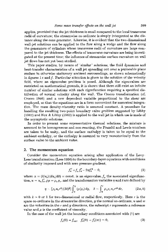
2. The momentum equation Consider the momentum equation arising after application of the Levy-
Lees transformation (Lees 1956) to the boundary-layer equations with conditions of similarity imposed and with zero pressure gradient,
where a = (s"/u,) (du,/ds") = const. is an eigenvalue, f a the associated eigenfunc- tion, u = u, f:, pp = prpr, and the transformation variables q and s" are defined by
with k = 0 or 1 for two-dimensional or radial flow, respectively. Here r is the space co-ordinate in the streamwise direction, y the normal co-ordinate, u and w are the velocities in the r and y directions, the subscript r represents a reference value and p is the coefficient of viscosity.
In the case of the wall jet the boundary conditions associated with (1) are
f a ( 0 ) =fa,, fL(0) =fL(a) = 0, (3)
600 Herbert Fox and Martin H . Steiger
where fa, 5 0 for suction or injection, and the subscript w refers to the condition at the wall.
In addition to the two-point boundary-value problem posed by (3), (1) also implies the existence of an eigenvalue problem. That is, for each value of a (which so far is unrestricted in the sense that it may take on any real value) only one solution fa with the correct asymptotic behaviour as 7 --f co can be found. Indeed, as 7 -+ co, (1) has a solution of the form fa = A In 7 + B + O( 1/11) + . . ., where A = A{ fa(O), a} and B are constants. It is desirable to require that f: decay exponentially as 11 + 00, then fa(co) must equal a constant which is possible only if A = 0. Two equations for the unique determination of fa(0) and a can be then obtained from (l), namely
(4 a)
and P m
J O
where f : ( c o ) = 0 has been assumed. (4a ) is obtained by integrating (1) from 7 = 0 to 7 = co, while ( 4 b ) is obtained by multiplying (1 by f a and then integrating.
There are several interesting features associated with (4). If i t is assumed that fl(0) 0, then (4a ) imposes the restriction a 6 - 8 since fL2, and hence
are always positive. Furthermore, (4a ) states that if fa(0) = 0 (blow-off), then a = -3; from ( 4 b ) it follows that
hence f-g must be an asymmetric function varying from f-4 = - f-$(co) at. the wall tof-g = f-a(co) as 11 + co. In addition, for fa(0) = 0 (impermeable surface), ( 4 b ) yields a = - 1 and (4a ) yields
f ” (0 ) = JomfI”ldri.
Clearly, a unique value of CI is attained for each value of fa(0) and therefore for each solution. For brevity, the subscript a will henceforth be omitted. It is interesting to note the following group property exhibited by (1) and (3), first pointed out by Glauert (1956). If fo(q) is a solution then f l = Afo(Aq) is also a solution for any value of the constant A .
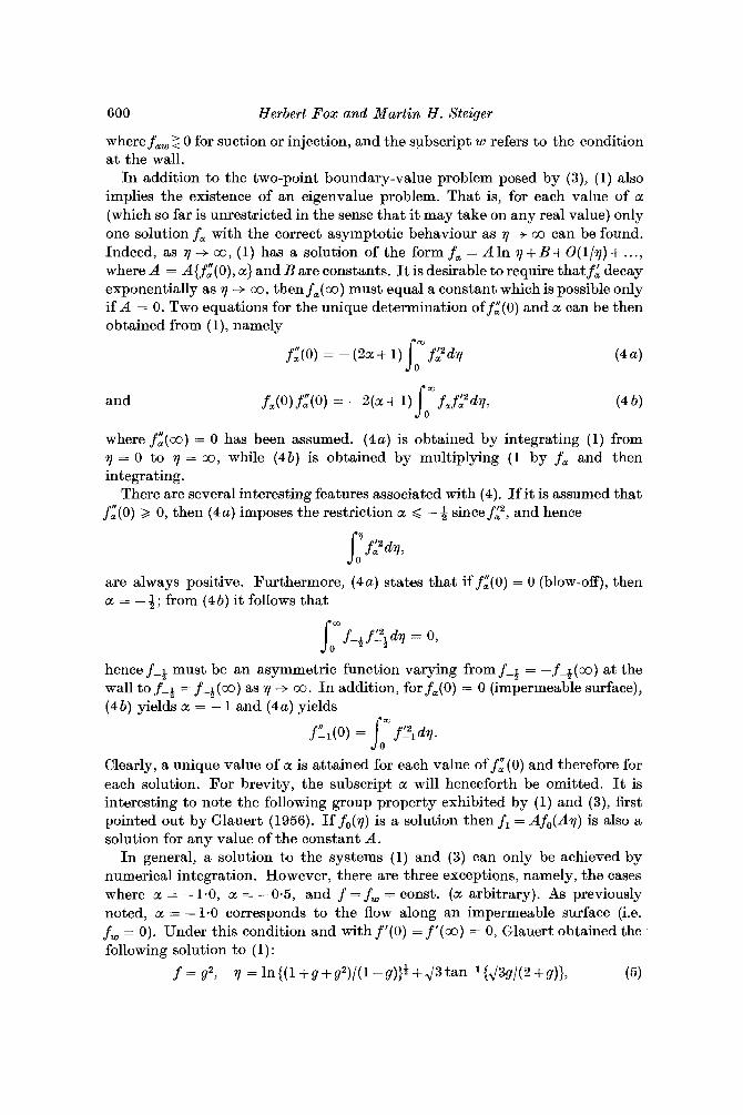
In general, a solution to the systems (1) and (3) can only be achieved by numerical integration. However, there are three exceptions, namely, the cases where a = - 1-0, a = -0.5, and f = f, = const. (a arbitrary). As previously noted, a = -1-0 corresponds to the flow along an impermeable surface (i.e. fw = 0). Under this condition and with f ’ ( 0 ) = f ’ ( m ) = 0, Glauert obtained the following solution to (1):
f = g2, 11 = ln{(l+g+g2)/(1-g))B+2/3tan-1{1/3g/(2+g)}, ( 5 )
Some mass transfer effects o n the wall je t 60 1
where, because of the group property, f (a) = 1 is assumed without loss in gener- ality. For a = - 0.5, (1) can be integrated to yield
f ” +flf = const. ( 6 a )
However, since f ” ( a ) = f ’ (co) = 0, the constant must also be zero. For ( 6 a ) to be valid at the wall, it follows that f i = 0; thus a = - + corresponds to blow-off. An additional integration of (6 a ) is possible and yields
f ’ + if2 = &f$, ( 6 b )
It should be noted that ( 6 ) is similar in form to those equations arising from R
study of the two-dimensional jet. However, for a complete matching it is neces- sary to change independent variables from 7 to, say, {) so that 7 = 0 corresponds to 6 = -a and 7 = 0 corresponds to { = +a. A transformation of this type, which must necessarily retain the form of ( 6 b ) , could not be found. In the third case, it is seen thatf = fw = const. is a solution to ( 1 ) and satisfies (3). However, f = const. requires that the streamwise velocity be identically zero everywhere, and therefore corresponds to a trivial solution.
Reduction to first-order equation and treatment of the two-point boundary-value problem
Following the method of Crocco (1946), the velocity ratio f ‘ = 6 is introduced as the independent variable and a shear function, f ” = G, is defined. Use of these variables in ( 1 ) results in
dG/dc = - f + ZCI(’/G, (7)
dfld6 = tP> (8)
at 6 = 0 (wall), f = f w ; (9)
as (+ 0 (outer edge), G + 0. (10)
subject to the boundary conditions
Note that ( = 0 a t both end-points; however, as will be seen, this introduces no difficulty in the integration scheme employed.
The transformation to ( as the independent variable and the introduction of G reduces ( 1 ) to a set of two non-linear, first-order differential equations which are amenable to standard techniques of numerical integration. However, an essential difficulty in numerical analysis is associated with the two-point nature of the boundary-value problem. The usual procedure for a given CI is to initiate the integration at the wall choosing a value off,. An arbitrary value of G , is chosen and the integration carried to the outer edge where in general the boun- dary condition is not satisfied. Guided iteration must then be performed on the value of G, such that (10 ) is indeed satisfied. However, there is no assurance that the particular value of a selected will admit a solution. Thus, even for these simple equations the solution becomes quite formidable.
Libby (1962), and more recently Fox & Libby (1962), employed a different technique in treating a two-point boundary-value problem; they used the
602 Herbert Fox and Martin H . Eteiger
asymptotic solution valid as 7 --f co. Consider then the solution of (1) for 4 large using the following appropriate approximations:
f - f m + f l , f ' - f 1 7 f " =!f:7 (11)
where f m = const., fl 4fm, and fi, f[ < 1. Insertion of (11) in (l), and neglecting products of fl and its derivatives results in
fY+ fm f;'= 0.
f -fm-k-lfm, G 2 . f m t .
Integration yields
The asymptotic solution given by (13) may be employed as follows. Choose va.lues of f m and < with [ 4 fm and compute values off and G . The integration of (7) and (8) is then carried out for increasing values of 5 until G -+ 0. At G = 0- a Taylor expansion is performed and new starting values are obtained for G = Of. It should be noted that this singularity at G = 0 is of the form G2 = a + bfl with f finite. The integration is then carried out for Ag < 0 to fl = 0. The only question that remains is whether, in fact, G -+ 0 as ,$ increases. Inspection of (7) for G < 0 reveals that for all cc < 0, G --f 0 as [ increases. Hence, use of this integration scheme allows the following limits on a to be inferred:
-co < a < - 1: f, > 0, suction; cc =-1: f w = 0;
a = -1. 2 . blow-off; - 1 < OL < -4: fw < 0, blowing;
- & < a < O : G w < O ;
a 3 0: solution does not exist,
Thus, by use of the asymptotic solution, iteration is eliminated and every com- puter run can be considered a valid solution. Note that for any cc within the described limits, once a solution is given, any f, may be obtained by use of the group property.
Once a solution is computed a final integration is necessary to obtain the profiles as functions of 7. In general, 7 may be written as
However, to integrate to the outer edge this must be altered as follows:
where & is the point where G = 0, fl, is the initial value of fl (at the outer edge), and sl/flc7 s2/flc < 1. The second integral in (15) may be evaluated about the singularity and yields
Some mass transfer effects on the wall jet 603
where Go denotes the value of G at 6 = <c-el. The numerical integration of (7) and (8) was performed using the Runge-Kutta integration scheme outlined by Gill (1951). In addition, a step-size criterion was programmed to allow the computer to choose its own step-size automatically. The solutions were carried out on a Bendix G-15 D computer where the running time per case was approxi- mately 35 minutes.
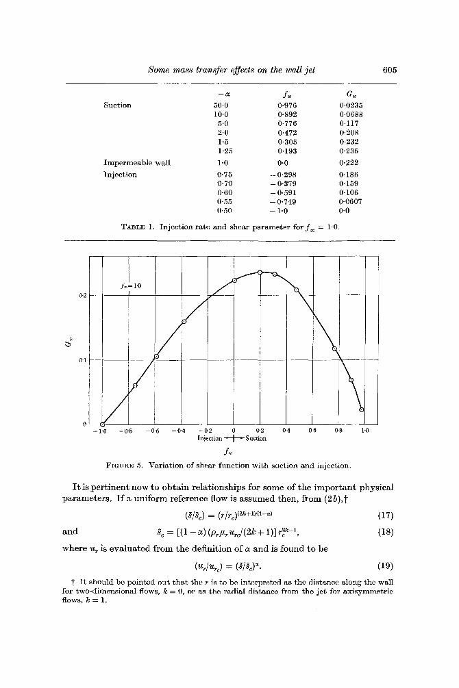
Presentation and discussion of results
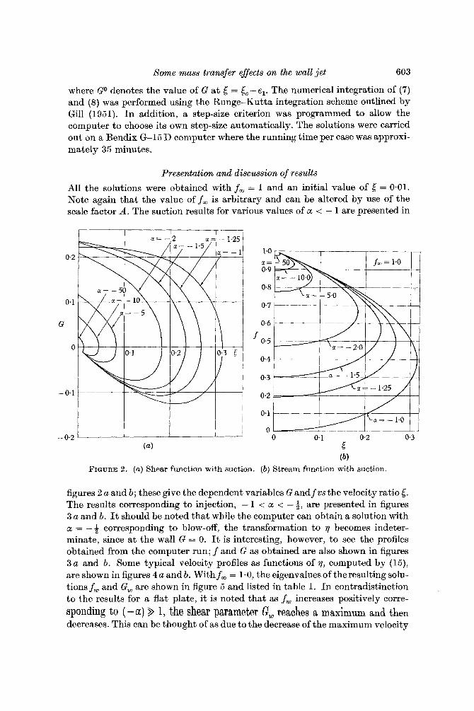
All the solutions were obtained with f m = 1 and an initial value of = 0.01. Note again that the value of f m is arbitrary and can be altered by use of the scale factor A . The suction results for various values of a < - 1 are presented in
-- 0.2 ' I I I (4 E
(b) FIGURE 2 . (a ) Shear function with suction. ( b ) Stream function with suction.
figures 2 a and b; these give the dependent variables G and f vs the velocity ratio 6. The results corresponding to injection, - 1 < a < - 9, are presented in figures 3 a and b. It should be noted that while the computer can obtain a solution with a = -+ corresponding to blow-off, the transformation to 7 becomes indeter- minate, since at the wall G = 0. It is interesting, however, to see the profiles obtained from the computer run; f and G as obtained are also shown in figures 3 a and b. Some typical velocity profiles as functions of 7, computed by (15), are shown in figures 4 a and b. With f m = 1.0, the eigenvalues of theresulting solu- tions f , and G, are shown in figure 5 and listed in table 1. In contradistinction to the results for a flat plate, it is noted that as f w increases positively corre- sponding to ( -a ) > 1, the shear parameter @, reaches a maximum and then decreases. This can be thought of as due to the decrease of the maximum velocity
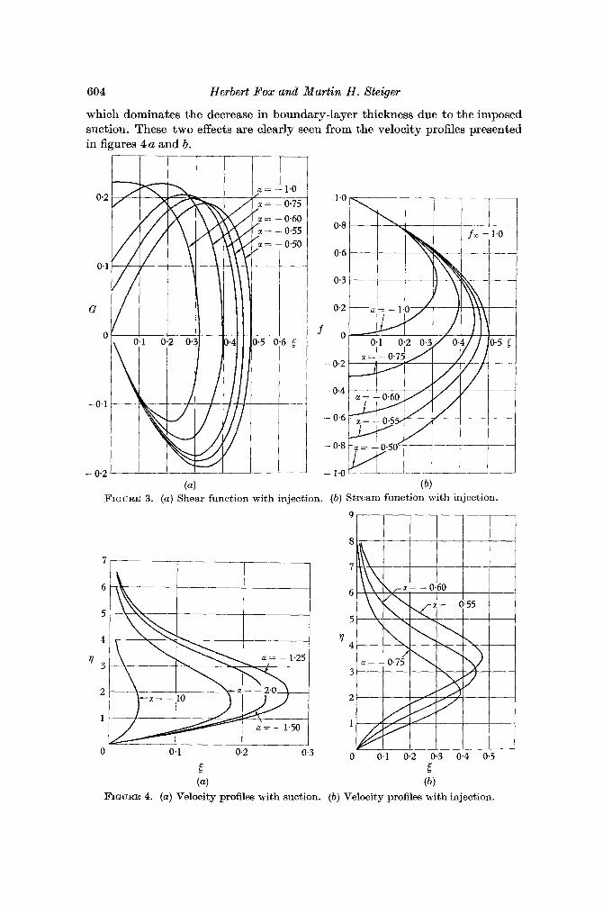
604 Herbert Pox and Martin H . Steiger
which dominates the decrease in boundary-layer thickness due to the imposed suction. These two effects are clearly seen from the velocity profiles presented in figures 4 a and b.
0.2
0.1
c
0
-0.1
- 0.2
FIGURE 3. (a) Shear function with injection. (b ) Stream function with injection.
9
8
7
6
5
% 3
2
1
0 0.1 0.2 0.3
5 E (4 ( b )
FIGURE 4. (a) Velocity profiles with suction. ( b ) Velocity profiles with injection.
Some mass transfer effects on the wall jet 605
-a f w G , Suction 50.0 0.976 0-0235
10.0 0-892 04688 5.0 0.776 0.117 2.0 0.472 0.208 1-5 0.305 0.232 1-25 0.193 0.235
Impermeable wall 1.0 0.0 0.222
Injection 0.75 - 0.298 0.186 0.70 - 0.379 0.159 0.60 - 0.591 0.106 0.55 - 0.749 0-0607 0.50 - 1.0 0.0
TABLE 1. Injection rate and shear parameter for f, = 1.0.
0.2
t;" 0 1
0 -1.0 - 0 8 -0.6 - 0 4 -02 0 0 2 0 4 06 0 8
Injection +Suction
fuJ FIGURE 5. Variation of shear function with suction and injection.
It is pertinent now to obtain relationships for some of the important physical parameters. If ;t uniform reference flow is assumed then, from ( 2 b ) , t
(g/gc) = (r/yc)(zk+1)/(1-4 (17)
and gc = [(I -a) (prprarc / (2k + 111 rc2k+1, (18)
( 4 a r J = (s"/gcP* (19)
where ur is evaluated from the definition of a and is found to be
t It should be pointed out that the r is to be interpreted as the distance along the wall for two-dimensional flows, k = 0, or as the radial distance from the jet for axisymmetric flows, x: = 1.
606 Herbert Fox and Martin H . Steiger
Here the subscript c refers to values at a reference station s,. By (17) , (19) can -
be rewritten in terms of r as (u,/u,.) = ( r/rc)a(2k+1)/(1-a)
and the velocity in jet can be shown to be
(u/urC) = f r ( r / , c )a (2k+ l ) ’ (1 -a ) . (21)
From the transformation given by ( 2 a, b ) it can be shown that the y-velocity component a t the wall, ww, is given by
w, = - p, u, r k ( 2d)-:f( 0).
1.5
1.4
1.2
1.0
0 0.8 5 2 .
0.6
0.4
0.2
9 0
1 2 3 4 5 6 7 8
Tire
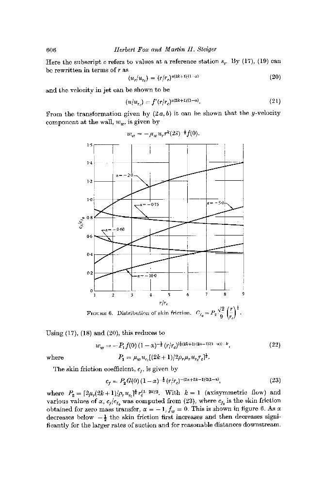
FIGURE 6. Distribution of skin friction. Cfo =
Using (17), (18) and (20), this reduces to
where Rt = ,uwu,[(2k + 1 ) / 2 P T P T ~ T C ~ C 1 * .
cf = p2 G ( 0 ) ( 1 - a)-& (r/rc)-(za+2k-l)i2(l-a),
The skin friction coefficient, cf, is given by
(23)
where P2 = [2,4(2k + 1)/pTurc]4 rLl--2k)/2. With k = 1 (axisymmetric flow) and various values of a, cf/cfo was computed from (23), where cfo is the skin friction obtained for zero mass transfer, a = - 1, fw = 0. This is shown in figure 6. As a decreases below -4 the skin friction first increases and then decreases signi- ficantly for the larger rates of suction and for reasonable distances downstream.
Xome mass transfer eflects on the waU jet 607
It is pointed out, however, that for suction cf /cfo increases monotonically with r/rc and that, as CL decreases, the exponent increases to a limit of + 1 for k = 1. Hence, at some large finite value of r/rc the skin friction is larger for the larger rates of suction.
If incompressible flow is assumed, the boundary-layer thickness 6 can be shown to be
6 = rle( 1 - , ) tP3(r / r , ) {~(2k+l ) ( l -2a)} -k , (24)
where P! = [2rcpu,/(21% + 1 ) prurc]&, and re is the value of 7 at the outer edge of the boundary layer and is chosen, say, when [ = 0.001 (at the outer edge).
3. The energy equation Some features of similar thermal solutions, for Prandtl and Lewis number
equal to unity, are now examined. The simplest solution is obtained for a very special case, namely, that in which H, = He = He,, where His the total enthalpy and the subscript e refers to conditions at the outer edge of the boundary layer. In this case the Crocco integral H = A + Bu (with A and B constants) can be used to satisfy the boundary conditions, yielding
where Hm, is the value of H evaluated at an initial station, re, and at the point where f' = f;,,. In this case the surface heat-transfer rate is given by
qwirw = - (Hmc-Hew)lurcf&ax (26)
and by (qW/qw,) = (r/rc)(-6ak-4a+1)/2(1-") (27 a )
where -
Here 7, represents wall shear stress and h is the thermal conductivity.
and ( 2 b ) to the usual boundary-layer energy equation and assuming that For cases in which He =t= H, similar solutions can be derived by applying (2a )
H-He = (H,-H,)g(n), H, = Hw(s"), He = const. (28)
Then it follows that S dH,
9'' + f g ' - 2Nf ' g = 0, where N ____ -- . H,-H, ds
Similar solutions are obtained from (29) only if
N = const. (30)
A different solution for g (denoted by g N ) is obtained from (29) for each pre- scribed value of N . It can be noted that (29) is linear a.nd any number of these solutions may be summed to form an additional solution. For each N , the follow- ing boundary conditions must be satisfied:
g ( 0 ) = 1.0, g(c0) = 0. (31)
608 Herbert Fox and Martin H . Xteiger
Combination of (28), (29) and (30) leads to the following permissible form of non-isothermal surface eiithalpy :
Hw = He + (H, - He), (a j~? , )~ . (32)
There is no restriction on the value of N ; it may be positive, negative, zero and not necessarily an integer.
The case of constant surfrce temperature is given by N = 0, for which (29) becomes
which has the solutioii g,”+fg; = 0,
where
(33)
It can be shown that go varies monotonically from 1 to zero. Therefore H varies monotonically from H, to He. This severely restricts the regime of usefulness of this solution; the enthalpy profile cannot be prescribed arbitrarily at an initial station, but must be accepted as it is obtained under the postulate of similarity. Thus, one must exclude those cases in which the initial stagnation enthalpy of the wall jet is less than He or greater than H,; at least up to the station where the enthalpy profile has deteriorated to an acceptable form. Furthermore, in this case heat must be passing from the surface into the stream when H > He. Note that these restrictions did not apply in the important special case (He = H,) given previously. The case of the non-similar thermal field downstream of an arbitrary enthalpy profile can be treated by approximate, iterative or numerical techniques. However, the present purpose is to explore only the properties of the similar solutions.
In the general non-isothermal case the heat flux may be expressed in terms of similar solutions as follows :
-4wx = (P,luwu,H,rk/(2s):)g:,(o), (35)
where (4zu/4WC)N = ( r c / V , 136)
where 2 k + 1 - 2 a k - 2 a + 1
2(1--a) 2(1--a) )
/j’= 2 N - - - -
The quantity qw, can be obtained by evaluating (35) at the station r = r,, q being the heat flux. For the non-isothermal case lengthy numerical procedures are required for the solution of the two-point boundary-value problem. How- ever, for one particular value of N , namely, N = - $, a closed form solution is possible. For this case (29) reduces to
(37) g” + fg’ + f ’g = 0,
which can be integrated to give 9‘ +fg = 0,
where g’(0) = - fw-
Xome mas8 transfer effects on the wall je t
Now (38) cam be integrated to yield
For N = - +, the distribution of enthalpy along the surface is given by
609
R E F E R E N C E S
BAKKE, P. 1957 An experimental investigation of a wall jet. J . Fluid Mech. 2, 467. BLOOM, M. H. & STEIGER, M. H. 1958 Some compressibility and heat transfer character-
istics of the wall jet. Proc. Third U S . Nat. Congr. Appl. Mech. p, 717. Brown Uni- versity.
BLOOM, M. H. & STEIGER, M. H. 1961 Perturbed boundary-layer solutions applied to the wall jet and Blasius profile. Dev. in Mech. 1, 588. Plenum Press: New York.
C R ~ C C O , L. 1946 The laminar boundary layer in gases. Momografie Scientifiche di Aero- nautica, no. 3, Minister0 della Defesa-Aeronautica, Rome ; also Rep. CF-1038, Aerophysics Laboratory, North American Aviation, Inc. 1948.
FOX, H. 6: LIBBY, P. A. 1962 Helium injection into the boundary layer at an axisym- metric stagnation point. J . Aero. Sci. 29, 921.
GEORGE, A. 1959 An investigation of a wall jet in a free stream. Princeton University Rep. no. 479.
GILL, S. 1951 A process for the step-by-step integration of differential equations in an automatic digital computing machine. Proc. Camb. Phil. Soc. 47, 96.
GLAUERT, M. B. 1956 The wall jet. J. Fluid Mech. 1, 625. GLAUERT, M. B. 1957 On laminar wall jets. Boundary Layer Research Symp. FreiburgIBr LEES, L. 1956 Laminar heat transfer over blunt-nosed bodies a t hypersonic flight speeds.
Jet Prop. 26, 259-69. LIBBY, P. A. 1962 The homogeneous boundary layer at an axisymmetric stagnation point
with large rates of injection. J . Aero. Sci. 29, 48. RILEY, N. 1958 Effects of compressibility on a laminar wall jet. J. Fluid Mech. 4, 615. SCHWARZ, W. H. & COSART, W. P. 1961 The two-dimensional turbulent wall jet. J . Fluid
Mech. 10, 481.
39 Fluid Mech. 16