Embed Size (px)
Citation preview
Some Factors to Consider in the Design of Bridge Foundations
Ralph E. Fadum
Assistant Professor of Soil Mechanics Purdue University
Engineers have learned from experience that a bridge failure is caused frequently either by an undermining of its foundations or by a movement of its abutments from the development of pressures from backfill material greatly in excess of the pressures for which the abutments were designed. The scope of this paper is restricted to the presentation of some data and theory pertaining to scour and earth pressure, and to a discussion of the importance of considering these factors carefully in the design of substructures supporting bridges over inland waterways.
Let us first consider the problem of scour. During flood flows, the shape and size of a channel change continuously in order to provide a minimum of resistance to the flow of water. These changes are effected by erosion at locations of high resistance to flow and a deposition of material at locations of comparatively low resistance. There is a continuous interchange of material along the entire stream bed. At sections where the change in velocity is great the quantity of material scoured out during flood stage will exceed that which is replaced simultaneously by sedimentation. The rise in the stage of the stream at such locations does not reflect the total increase in size of the stream channel.
The erosive power* of flowing water is discussed by Longwell, Knopf, and Flint.1 They state: “Experiments and calculations indicate that if the velocity of a stream be doubled, its abrasive power is increased about four times . . . its capacity to transport rock fragments of a given size is increased, under some conditions, as much as 32 times . . . The volume of the largest rock fragment . . . that it can move by pushing or rolling may be increased up to 64 times.” As an illustration they cite the following interesting examples:
When the St. Francis Dam near Los Angeles gave way in1928 and sent a flood down the valley below, blocks of concrete
1 Longwell, Knopf, and Flint—“Textbook of Geology, Part I, Physical Geology”, 2nd Ed., John Wiley and Sons, 1939, p. 61.
25
26 PURDUE ENGINEERING EXTENSION DEPARTMENT
weighing up to 10,000 tons each were moved by the escaping water. In India during the Gohna flood of 1895, which lasted just four hours, the water picked up and transported such quantities of gravel that, through the first thirteen miles of its course, the subsiding stream made a continuous gravel deposit 50 to 234 feet thick.
There are many factors which determine the probable depth to which a stream bed w ill be eroded at a proposed bridge site. The most important among these are the following:
1. The type of soil constituting the stream bed.2. The shape and alignment of the channel, both at and immedi
ately above and below the site of construction.3. The effect of restricting a channel by the construction of piers
and abutments.4. The hydrology of the drainage basin which feeds the stream,
particularly with respect to its effect on the intensity and duration of flood flows.
A careful analysis of the influence of these various factors will lead, at best, only to an approximate answer to the question : How deep must foundations extend to guarantee safety against underscour ?
An engineer can easily be tempted to construct a bridge foundation which extends to an insufficient depth below the elevation of a normal- stream bed. From the point of view of load-carrying capacity he can ask for nothing better than the good grade of gravel which he often finds. He knows that this type of material w ill support safely a high intensity of load, provided only that it is not underlain by an inferior material, and that the foundation structure which he designs is protected by an adequate cover of soil to eliminate frost action. He knows from experience that it is difficult to install deep foundations in such a material—nature discourages him from installing a deep foundation. Nature, up to her old tricks, is not satisfied merely to set this trap. She also knows wh e r e to place it. From the point of view of economy the engineer seeks a narrow crossing for a bridge location. It is just at such a location that velocities are changed most during high-water stages, and the degree of obstruction to flow caused by the construction of piers and abutments is the highest. It is not surprising, therefore, that even after the erosion problem is investigated and good engineering judgment is exercised, failures due to undermining of foundations are frequent. These failures, however, may he made to serve a useful purpose. They furnish full-scale-model test data. The writer wishes to present some of these data in the hope that some light w ill be shed
THIRTIETH ANNUAL ROAD SCHOOL 27
on the influence of the various factors which determine the depth to which a stream bed may be eroded.
The following records are cited in a paper presented by Dr. Karl Terzaghi2 at the first International Conference on Soil Mechanics and Foundation Engineering:
1. Systematic soundings made by engineers of the U. S. Bureau of Reclamation at a location on the Colorado River near Yuma showed that, while the water level rose 12 feet, the river bed, consisting of fine, clean, and silty sand, and river silt, was scoured to a depth of 40 feet.
2. In Colorado a bridge pier constructed in a torrential river, and founded at a depth of 10 feet below river bottom on a bed of boulders up to eight cubic feet in size, failed during the first high-water period following construction.
3. Soundings made by F. Schaffernak in the Drau River in Austria showed that as the water level rose three feet the river bed, consisting of cobbles several inches in diameter, was scoured to a depth of 13 feet.
4. A bridge pier in the eastern United States, founded on a stratum of gravel which was seven-feet thick and which was covered by an eight-foot blanket of mud, settled two feet during a flood. From records it appeared probable that the entire mud deposits were replaced during each flood.
5. One of the piers of the Jetzel Bridge near Hitzacker, Germany, founded at a depth of 14 feet below the surface of the flood plane on sand, was undermined during a period of exceptionally high water.
From a study of these records Terzaghi concludes:Reliable empirical rules for estimating the depth of scour can
only be obtained from numerous soundings performed during low- and high-water seasons under different hydrological and geologic conditions. The publication of pertinent data would be highly desirable. The records quoted lead to a tentative conclusion that the depth of scour in soils with little or no cohesion is likely to assume values of the order of three or four times the rise in the river stage.The following examples further illustrate what can happen if a
bridge foundation does not extend sufficiently below the stream bed to prevent the possibility of underscouring:
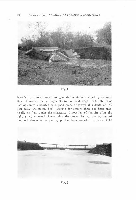
The wreckage of a small 20-foot slab bridge is shown in Fig. 1. This failure occurred approximately three years after the bridge had
2 Terzaghi, Karl—“Failure of Bridge Piers Due to Scour”, Proceedings of the International Conference on Soil Mechanics and Foundation Engineering, 1936, Vol. II, p. 264.
28 PURDUE ENGINEERING EXTENSION DEPARTMENT
Fig. 1
been built, from an undermining of its foundations caused by an overflow of water from a larger stream in flood stage. The abutment footings were supported on a good grade of gravel at a depth of 4^2 feet below the stream bed. During dry seasons there had been practically no flow under the structure. Inspection of the site after the failure had occurred showed that the stream bed at the location of the pool shown in the photograph had been eroded to a depth of 15
Fig. 2
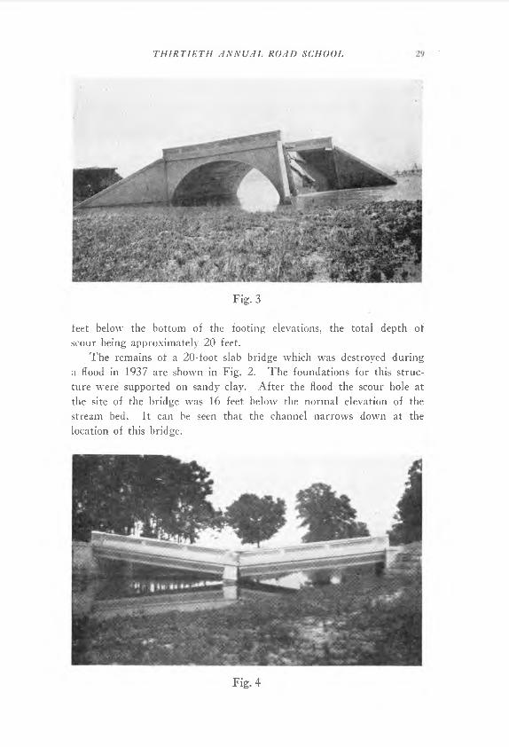
Fig. 3
THIRTIETH ANNUAL ROAD SCHOOL
feet below the bottom of the footing elevations, the total depth of scour being approximately 20 feet.
The remains of a 20-foot slab bridge which was destroyed during a flood in 1937 are shown in Fig. 2. The foundations for this structure were supported on sandy clay. After the flood the scour hole at the site of the bridge was 16 feet below the normal elevation of the stream bed. It can be seen that the channel narrows down at the location of this bridge.
Fig. 4
30 PURDUE ENGINEERING EXTENSION DEPARTMENT
Fig. 5
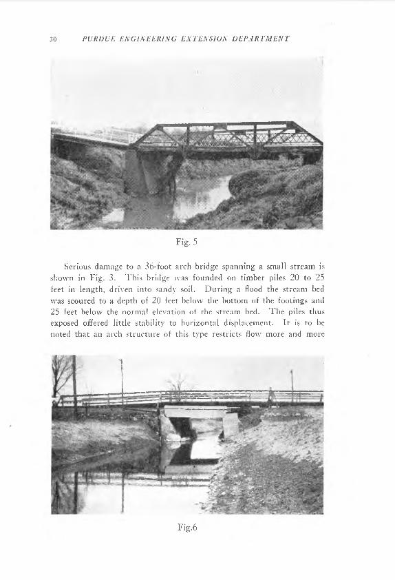
Serious damage to a 36-foot arch bridge spanning a small stream is shown in Fig. 3. This bridge was founded on timber piles 20 to 25 feet in length, driven into sandy soil. During a flood the stream bed was scoured to a depth of 20 feet below the bottom of the footings and 25 feet below the normal elevation of the stream bed. The piles thus exposed offered little stability to horizontal displacement. It is to be noted that an arch structure of this type restricts flow more and more
Fig.6
THIRTIETH ANNUAL ROAD SCHOOL 31
as the water level rises during a flood stage. The greater the restriction, the greater the increase in velocity of the water flowing under it; and, as a consequence, it might be anticipated in this case that the rate of scouring increased very considerably as the water level rose during the flood period.
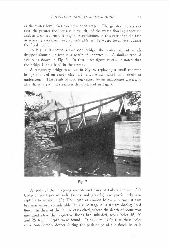
In Fig. 4 is shown a two-span bridge, the center pier of which dropped about four feet as a result of underscour. A similar type of failure is shown in Fig. 5. In this latter figure it can be noted that the bridge is at a bend in the stream.
A temporary bridge is shown in Fig. 6, replacing a small concrete bridge founded on sandy clay and sand, which failed as a result of underscour. The result of scouring caused by an inadequate waterway at a sharp angle in a stream is demonstrated in Fig. 7.
Fig. 7
A study of the foregoing records and cases of failure shows: (1)Cohesionless types of soils (sands and gravels) are particularly susceptible to erosion. (2) The depth of erosion below a normal stream bed may exceed considerably the rise in stage of a stream during flood flow. In three of the failure cases cited, where the depth of scour was measured af t er the respective floods had subsided, scour holes 16, 20 and 25 feet in depth were found. It is quite likely that these holes were considerably deeper during the peak stage of the floods in each
32 PURDUE ENGINEERING EXTENSION DEPARTMENT
case. (3) Scouring action is particularly acute at locations of changes in width and alignment of a channel, or at locations obstructed by piers and abutments.
The cases cited prove the necessity of installing deep foundations, particularly at locations where a channel is restricted. The depth to which a stream may scour during high-water periods depends upon many factors; but it appears, on the basis of the limited data available, that Terzaghi’s tentative conclusion that “the depth of scour in soils with little or no cohesion is likely to assume values of the order of three to four times the rise in river stage” might furnish a rough basis for design at such critical locations.
It was of interest to note the following statement pertaining to the design of foundations for bridges for the Alaskan military highway in a recent issue of The Highi vay Magaz in e 'A “Where deep scour was not anticipated the piers were placed on gravel at a minimum depth of 17 feet below stream bed.”
Another factor meriting special consideration, but often not given the attention it deserves in the design of bridge abutments, is that of earth pressure. An abutment must serve not only as a pier but also as a retaining wall, and its stability as judged by an application of the laws of statics is largely determined by the intensity and location of the point of application of the resultant pressure exerted by backfill material. As an approximation for determining the lateral pressure, the soil which is used as a backfill material is sometimes considered to act as a fluid having a weight equal to 3CH and 353 4 5 pounds per cubic foot. Such an assumption automatically fixes the distribution of the earth pressure and locates the position of the resultant pressure at a distance of one-third of the vertical height of the wall above its base. It inherently implies: (1 ) that the back of the wall offers no frictional resistance to the wedge of the soil which it retains; (2) that the internal resistance of the soil is fully mobilized along a potential sliding surface; and (3) that the backfill material is well drained, otherwise the fluid pressure of the water alone would be 62.4 pounds per cubic foot.
3 “Drainage Problems on the Alaska Highway’’, The Highivay Magazine, published by members of the Armco Drainage Products Association, December, 1943, Vol. 34, p. 136.
4 Jacoby and Davis—“Foundations of Bridges and Buildings”, 3rd Ed., McGraw-Hill Book Company, p. 487.
5 Hewes—“American Highway Practice”, John Wiley and Sons, Vol. II, p. 376.
THIRTIETH ANNUAL ROAD SCHOOL 33
The theories of Rankine and Coulomb have been used most extensively as a basis for earth-pressure computations. These theories in themselves are sound, but they are often applied to cases to which they are inapplicable. To appreciate the limitations of these theories it is necessary to examine the assumptions upon which each is based and then to determine whether or not these assumptions are approximately realized in a practical problem.
Terzaghi6 has made a critical review of these methods. He has pointed out that, according to Rankine’s theory, a negligible compression or expansion of a mass of soil should be sufficient to mobilize its internal resistance completely.
To obtain a mental picture of what is meant by internal resistance it might be helpful to consider a mass of cohesionless soil to act somewhat like a mass of small spheres, each one of which is loosely tied to its neighbor by a small rubber band. As long as such a mass is not compressed or expanded, the rubber bands do not in any way help to tie the mass together; however, if that mass is permitted to expand, or if it is compressed by the application of some external force, then the rubber bands come into play and help to resist movements of one sphere with respect to another—the mass develops internal resistance.
According to Rankin’s theory, it is tactly implied that a negligible movement should be sufficient to change the state of stress in a mass of soil from the active to the passive state. The ac t i ve state corresponds to the condition which is reached when the mass is permitted to expand until the internal resistance is fully mobilized. In the case of a large mass of cohesionless soil having a horizontal surface, the ratio between the horizontal and vertical pressures for this condition, as determined
from Rankine’s earth-pressure theory, is equal to tan2 (45° ± ) 2 ’wherein <f> = the angle of internal friction. Assuming a typical value of 34° for the angle of internal friction, the horizontal pressure at any depth for this condition would equal 0.28 the vertical pressure. This horizontal pressure, which is the minimum pressure required to maintain equilibrium, is often used as a basis for design. The passive state of stress is obtained when the mass is compr es s ed until the internal resistance is fully mobilized. The ratio between the horizontal and vertical pressures for a large mass of cohesionless material having a
horizontal surface is, in this case, equal to tan2 (45° ; for an
6 Terzaghi, Karl—“Fundamental Fallacy in Earth Pressure Computations”, Journal of The Boston Society of Civil Engineers, April, *1936.
3 4 PURDUE ENGINEERING EXTENSION DEPARTMENT
angle of internal friction equal to 34 the horizontal pressure would be equal to 3.54 times the vertical pressure. The range in intensity of horizontal pressure for these limiting conditions is seen to he very large, the actual value depending entirely on deformation conditions.
Experiments cited hv Terzaghi6 in which a sand was deposited in a box with perfectly frictionless rigid immovable sides indicated that the ratio of horizontal to vertical pressures is for a dense sand 0.40 to0.45 the vertical pressure, and for a loose sand 0.45 to 0.50 the vertical pressure. In order to change the intensity of lateral pressure corresponding to this so-called condition of earth pressure at rest to the limiting values as determined by Rankine’s earth-pressure theory, it is necessary that the mass of sand be either stretched or compressed quite noticeably. Furthermore, according to Rankine’s theory of earth pressure, it must be assumed that no frictional resistance is developed between the back of a wall and the soil adjacent to it. Terzaghi points out that the opportunity for obtaining the movements which are required to develop the state of stress in a backfill corresponding to that assumed in Rankine’s theory does not exist in nature. He concludes that “the fundamental assumptions of Rankine’s earth pressure theory are incompatible with the known relations between stress and strain in soils, including sand. Therefore, the use of this theory should he discontinued.”
The basic assumptions of Coulomb’s theory7 of earth pressure pertaining to cohesionless soils are as follows: (1) At the instant of failure of a lateral support, a wedge of soil descends along an inclined surface. Coulomb assumed this surface to be plane. (2) At the instant of failure the internal resistance of the soil along this plane surface of failure is completely mobilized.
On the basis of these two assumptions it is possible to determine the magnitude of the resultant pressure which a retaining wall must exert against the wedge to prevent it from slipping downward. However, the position of this resultant pressure is not fixed by these two assumptions alone. Coulomb simply assumed that the intensity of lateral pressure was proportional to depth.
Terzaghi points out that no serious objection can be raised to the first two of these assumptions. Under normal conditions a wall retaining a cohesionless material w ill yield a sufficient amount to reduce the intensity of the total lateral pressure to the minimum value as deter-
7 The same assumptions are implied in the convenient graphical solutions devised by Culmann and Engesser. See, for example, Theoretical Soil Mechanics by Karl Terzaghi, John Wiley and Sons, 1943, pp. 81-83.
THIRTIETH ANNUAL ROAD SCHOOL 35
mined by Coulomb’s solution. In order to satisfy, the third assumption —that the lateral pressure is proportional to depth—requires a much larger yield. If a well-compacted sand is filled in back of a wall, the top of the support must yield a distance equal to at least l/s~inch per 20-foot height of wall to satisfy the condition imposed by this latter assumption. If the sand is loosely compacted, a larger yield would be required. If the top of the wall is held fixed in position, as it might be in the case of a rigid-frame bridge, it is likely that the distribution of earth pressure would be such that the resultant pressure would act at a position considerably higher than one-third of the vertical height of the wall.
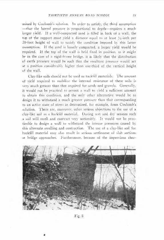
Clay-like soils should not be used as backfill materials. The amount of yield required to mobilize the internal resistance of these soils is very much greater than that required for sands and gravels. Generally, it would not be practical to permit a wall to yield a sufficient amount to obtain this condition, and the only other alternative would be to design it to withstand a much greater pressure than that corresponding to an active state of stress as determined, for example, from Coulomb’s solution. There are, moreover, other serious objections to the use of a clay-like soil as a backfill material. During wet and dry seasons such a soil will swell and contract very noticeably. It would not be practicable to design a wall to withstand the intense pressures caused by this alternate swelling and contraction. The use of a clay-like soil for backfill material may also result in serious settlement of slab sections at bridge approaches. Furthermore, because of the impervious char- *
Fig. 8
*
36 PURDUE ENGINEERING EXTENSION DEPARTMENT
acter of clays, weep-holes are comparatively ineffective in providing drainage of the backfill and, as a consequence, the wall may be subject to a full hydrostatic pressure during periods of heavy rains, or after flood waters have receded. If the wall is supported on a clay-like soil the condition becomes even more critical. As the soil soaks up water, its supporting capacity decreases.
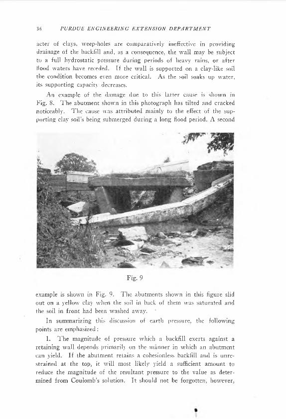
An example of the damage due to this latter cause is shown in Fig. 8. The abutment shown in this photograph has tilted and cracked noticeably. The cause was attributed mainly to the effect of the supporting clay soil’s being submerged during a long flood period. A second
Fig. 9
example is shown in Fig. 9. The abutments shown in this figure slid out on a yellow clay when the soil in back of them was saturated and the soil in front had been washed away.
In summarizing this discussion of earth pressure, the following points are emphasized:
1. The magnitude of pressure which a backfill exerts against a retaining wall depends primarily on the manner in which an abutment can yield. If the abutment retains a cohesionless backfill and is unrestrained at the top, it w ill most likely yield a sufficient amount to reduce the magnitude of the resultant pressure to the value as determined from Coulomb’s solution. It should not be forgotten, however,
THIRTIETH ANNUAL ROAD SCHOOL 37
that the resultant pressure determined from this solution, or from the various cqnvenient graphical solutions which are based on the same assumptions, is the minimum pressure that a wall can be designed to withstand safely.
2. The location of the point of application of the resultant earth pressure, which is determined by the distribution of the pressure against an abutment, is even more vitally dependent on the manner in which the abutment can yield. A greater movement is required to obtain an increase in pressure proportional to depth than is required to reduce the resultant pressure to the minimum value. If an abutment is so constructed that it cannot yield, the resultant pressure will act at a position higher than one-third the height of the wall. It can act at a position as high as the mid-point of the wall.
3. If adequate drainage is not provided by the installation and careful maintenance of weep-holes, the total pressure acting on a wall can be more than twice the magnitude of the pressure due to the earth alone. If a wall is designed to withstand only this pressure, particular care should be exercised to provide adequate drainage during backfill operations. A construction engineer is sometimes tempted to plug up weep-holes during this operation in order to compact the backfill material more conveniently. To discourage this practice, the Public Roads Administration stipulates the following specification pertaining to the backfill of structures: “Jetting of fills is prohibited, and approved mechanical ramming is required.”
4. The use of clay-like material for backfill purposes should be avoided. The pressure that such a material might exert against the wall is highly indeterminate, and it w ill in any case be considerably larger than that exerted by a cohesionless type of soil.