Embed Size (px)
Citation preview
Some Aspects of Electric Power Equipment Modelling
through Sustainability Key Concepts
CORNELIA A. BULUCEA1 DORU A. NICOLA1 MARC A. ROSEN2
NIKOS E. MASTORAKIS3 CARMEN A. BULUCEA4
1Faculty of Electrical Engineering, University of Craiova
ROMANIA 2Faculty of Engineering and Applied Science, University of Ontario Institute of Technology
CANADA 3Military Institutes of University Education, Hellenic Naval Academy
GREECE
4Faculty of Medicine, University of Medicine and Pharmacy of Craiova
ROMANIA
Emails: [email protected], [email protected], [email protected], [email protected],
Abstract: Enhancements are made to the concept that technical systems and processes involving energy
conversion, and particularly electric power equipment, need to be linked to environment engineering, since the
concept of sustainable development should emphasize two complementary aspects. The first is related to the
design of electrical equipment in order to achieve high energy efficiency during all life stages of a system, and
the second takes into consideration the environmental impact of technical systems operation, since biological
ecosystems generally are not free of anthropogenic influences. These are the reasons that, over the last few
decades, international legislation has required environmental impact assessment to be carried out for all phases
of the life electrical equipment, according to Life Cycle Assessment, which includes the production, use and
end-of-life phases. Following the notion that Nature demonstrates sustainable energy conversion, this work
focuses on highlighting that industrial ecology permits an alternate view of anthropogenic applications, related
both to technical and environmental reference systems. The study addresses some aspects, using energy
conversion processes during the operation of power transformers and induction motors as modeling examples
of sustainable electric equipment. Based on the model equations, this article presents the structural diagrams
method, as a modeling method for a three-phase electric transformer and induction motor in dynamic regimes,
according to an ecosystem pattern. The overall objective is to enhance understanding of how anthropogenic
activities can be viewed in concert with the entire system on Earth.
Key-Words: Electric power equipment, electromagnetic torque, exergy, induction motor, power transformer,
structural diagram, sustainability dynamics
1 Introduction Electrical power is used all over the world, and
standards of life and development of civilization are
often interpreted in correlation with the use of
electricity [1-6]. Nonetheless, concerns and questions
have been raised regarding, how to achieve a
sustainable industrial metabolism. Integrating
technical and ecological aspects represents a
significant challenge to humanity within the present
industrial world. In line with this idea, sustainability
concepts can help improve understanding of the
efficiencies of electric power equipment and
systems and guide improvement efforts [1-14].
Traditionally, the basic concepts of energy, exergy
and embodied energy are founded in the fields of
physics and engineering, although they have
environmental and economical significance as well.
These concepts can be explained, interpreted and
applied in a more universal manner, due to their
multidisciplinary traits [1-3,13-16].
Taking a holistic view, this study focuses on
highlighting that industrial ecology permits an
alternate view of anthropogenic applications, related
WSEAS TRANSACTIONS on POWER SYSTEMSCornelia A. Bulucea, Doru A. Nicola, Marc A. Rosen,
Nikos E. Mastorakis, Carmen A. Bulucea
E-ISSN: 2224-350X 268 Volume 10, 2015
both to technical and environmental reference
systems.
In line with this idea, in order to enhance thinking
that anthropogenic activities can and should be
viewed in concert with the entire system on Earth,
this study addresses some aspects, considering
energy conversion processes during the operation of
power transformers and induction motors, by
modelling an electric power transformer in the life
use phase, and an induction motor operating within
an electrically driven system according to an
industrial ecosystem pattern. Based on the model
equations, the article presents the structural diagram
method, as a modeling method for a three-phase
electric transformer and induction motor in dynamic
regimes, within the framework of industrial ecology.
2 Power Transformer Modelling
through Structural Diagram Method Three-phase transformers are widely used since
three phase power is the widespread way to
produce, transmit and use electrical energy [1-2,16-
20]. A three-phase transformer transfers electric
power from the three-phase primary winding
through an inductively coupled three-phase
secondary winding, changing values of three-phase
RMS voltage and current. Most commonly, the
transformers windings are wound around a
ferromagnetic core [1,20].
Over the last few decades, international legislation
have required environmental impact assessment be
carried out for all phases of transformer life [1,16-
20], according to Life Cycle Assessment tool, which
includes the production phase, use phase and end-
of-life phase. Modelling of all these transformer life
stages might offer solutions for further improvement
potential, focusing on technologies that reduce the
electricity losses during the use phase, and on
alternative materials for reducing human health and
environmental impacts [1, 16-20].
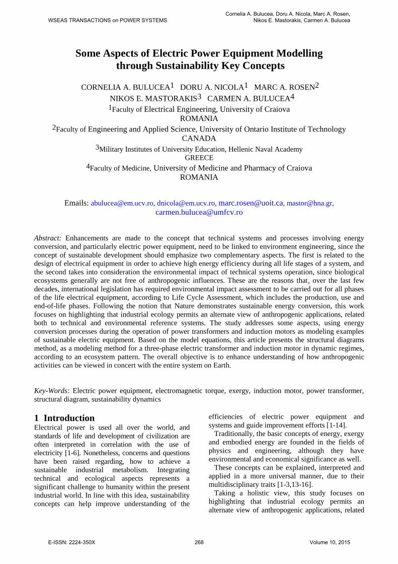
The operation principle of a three phase transformer
follows. Varying currents flowing in the primary
winding (due to the varying phase voltages uA, uB and
uC) create a varying magnetic flux in the transformer
core, and thus a varying magnetic field through the
secondary winding [1,18]. This varying magnetic field
induces a varying electromotive force in the
secondary winding. If a three-phase electric load is
connected to the secondary winding, electrical energy
is transferred from the primary circuit through the
transformer to the load. Since ua, ub and uc are the
secondary phase voltage, the load three-phase currents
system ia, ib and ic will be at the same time the
transformer secondary winding currents system. Note
that these currents represent the feedback (or inverse
reaction) between the electric load and the power
transformer. In line with this idea, the three-phase
transformer representation as an industrial ecosystem
is depicted in Fig. 1.
Fig. 1 Three-phase transformer representation
Since efficiency standards can be expressed in
terms of electrical efficiency depending on load
characteristics, in an attempt to improve the power
transformer efficiency, the structural diagram
method is presented below for analyzing the three-
phase transformer operation in the life use phase.
The classic models, meaning the equivalent
electric schemes and the phasor diagrams of power
transformer, could be considered only in a
permanent regime operation, when all the state
quantities have a sinusoidal variation in time. In
dynamic regimes, they lose their validity and other
models should be developed [1,18].
As a principle, with electrical transformer
modelling one can understand the use of
conventional representations (geometric
constructions, electrical circuits, structural diagrams
etc.) to describe the behavior (or for the simulation)
WSEAS TRANSACTIONS on POWER SYSTEMSCornelia A. Bulucea, Doru A. Nicola, Marc A. Rosen,
Nikos E. Mastorakis, Carmen A. Bulucea
E-ISSN: 2224-350X 269 Volume 10, 2015
of various operation states or regimes [2,14].
Physically, dynamic regimes of electric
transformers are characterized by the variation in
time of “electromagnetic status”, meaning the
currents and fluxes. Qualitatively, the dynamic
phenomena of an electromagnetic nature in the
electric transformers are fast are develop with small
time-constants (usually, between 1 and 100 ms).
In this study the three-phase electromagnetic
phenomena will be described into the space phasors
theory, taking into consideration the relations [18]:
)ia + ia + i(3
2 = i
)ua + ua + u(3
2 = u
)ia + ia + i(3
2 = i
)ua + ua + u(3
2 = u
c2
ba2
c2
ba2
C2
BA1
C2
BA1
(1)
With space phasors the modeling representation of
the three-phase transformer becomes identical with
that of the single phase transformer [18-19]. The
distinction between them is of pure mathematical
nature, emphasizing that in case of three-phase
transformer all variables, including the external ones
(u1 = primary voltage; i1 = primary current; u2 =
secondary voltage and i2 = secondary current), as well
as the internal ones are not real but complex
mathematical quantities. In this context, in the study
of the three-phase transformer one can use the space
phasors equations, and the structural diagrams will
encompass the complex quantities.
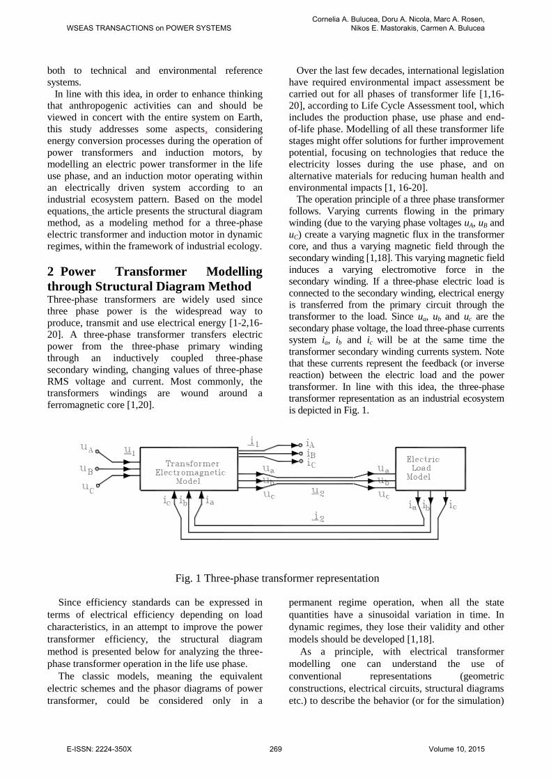
According to space phasors relations (1) and taking
into consideration the relations for three-phase system
reconstituting, in Fig.2 and Fig.3, respectively had
been represented two generic patterns (as a form of
structural diagram) of the variables transformation.
These models are corresponding, respectively, to the
phase quantities triplet vA, vB, vC which built the space
phasor v1 (direct transformation in fixed coordinates)
and to the rebuild of the phase variables vA, vB, vC
(reverse transformation in fixed coordinates),
according to the following relations:
v + }va{ Re = v
v + }va{ Re = v
v + }v{ Re = v
01
2-C
01
1-B
01A
(2)
where )v + v + v(3
1 = v CBA0 represents the zero
sequence component of the three-phase system, and
} { Re denotes the real part of the complex quantity
(between braces).
Mathematically, the processes dynamics of
electric transformers are described by differential
equations which, in most cases, are nonlinear. Based
on the mathematical model equations, we present
the structural diagrams method in this study, as a
modeling method of electric transformers for the life
use phase in dynamic regimes. One benefit of this
approach is derived from the easy conversion of
structural diagrams in Matlab-Simulink
implementations [1-2,18-19].
Basically, a structural diagram [1,18] represents
the graphical image of the differential equations
corresponding to the mathematical model of the
dynamic regime of the physical system taken into
account. Hence, real or complex variables are
represented by lines with arrows and graphical
symbols are associated with the mathematical
operations effected on the variables. In this context,
a number of “arrangements” are described in which
mathematical equations (equations of voltages and
fluxes) of the three-phase electric transformer can
be represented directly by structural diagrams. Since
in the structural diagrams, the variables are always
represented by lines with arrows, the load current i2
(which are flowing through the secondary winding)
represent the feedback reaction between the power
transformer and the electric load (connected at the
secondary winding terminals).
Fig.3 Pattern of phase quantities
vA, vB, vC rebuild from space phasor v1
Fig.2 Pattern of space phasor v1
built with phase quantities vA, vB, vC
WSEAS TRANSACTIONS on POWER SYSTEMSCornelia A. Bulucea, Doru A. Nicola, Marc A. Rosen,
Nikos E. Mastorakis, Carmen A. Bulucea
E-ISSN: 2224-350X 270 Volume 10, 2015
For a three-phase transformer, electrically and
magnetically symmetric, one could obtain the
equations corresponding to the mathematical
pattern, written with phase quantities space phasors
in fixed coordinates, according to the following
system:
)w
w(-)u(- = u
iw
w = i
i = i + i
+ iL =
+ iL =
dt
d + iR = u -
dt
d + iR = u
1
2
22
2
1
2
2
121
u1222
u1111
2
222
1
111
'
'
'
'''
'
'''
(3)
where u1 = primary voltage; i1 = primary current; u2 =
secondary voltage; i2 = secondary current; =
primary magnetic flux; = secondary magnetic flux;
= main (useful) magnetic flux; i = magnetizing
current; R1 = primary phase resistance; R2 =
secondary phase resistance; L1 = primary leakage
inductance; and L2 = secondary leakage inductance.
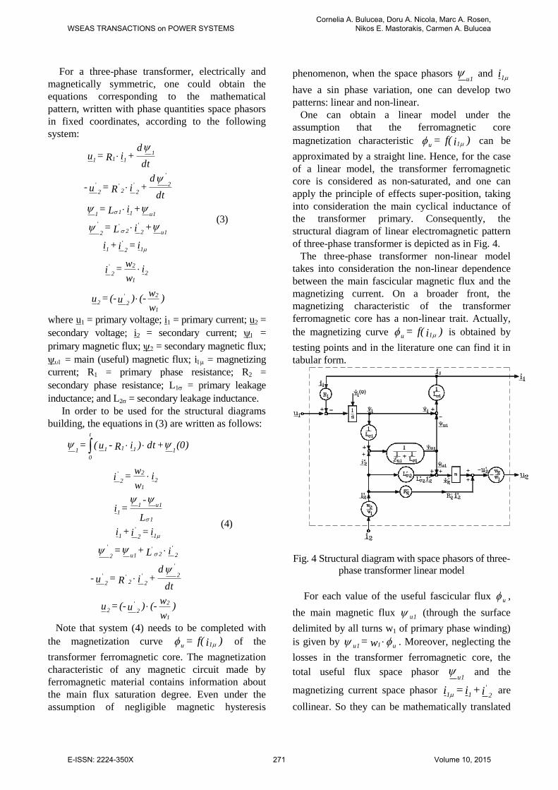
In order to be used for the structural diagrams
building, the equations in (3) are written as follows:
)w
w(-)u(- = u
dt
d + iR = u -
iL + =
i = i + i
L
- = i
iw
w = i
(0) + dt)iR - u( =
1
2
22
2
222
22u12
121
1
u11
1
2
1
2
2
1111
t
0
1
'
'
'''
'''
'
'
(4)
Note that system (4) needs to be completed with
the magnetization curve )if( = 1u of the
transformer ferromagnetic core. The magnetization
characteristic of any magnetic circuit made by
ferromagnetic material contains information about
the main flux saturation degree. Even under the
assumption of negligible magnetic hysteresis
phenomenon, when the space phasors u1
and i1
have a sin phase variation, one can develop two
patterns: linear and non-linear.
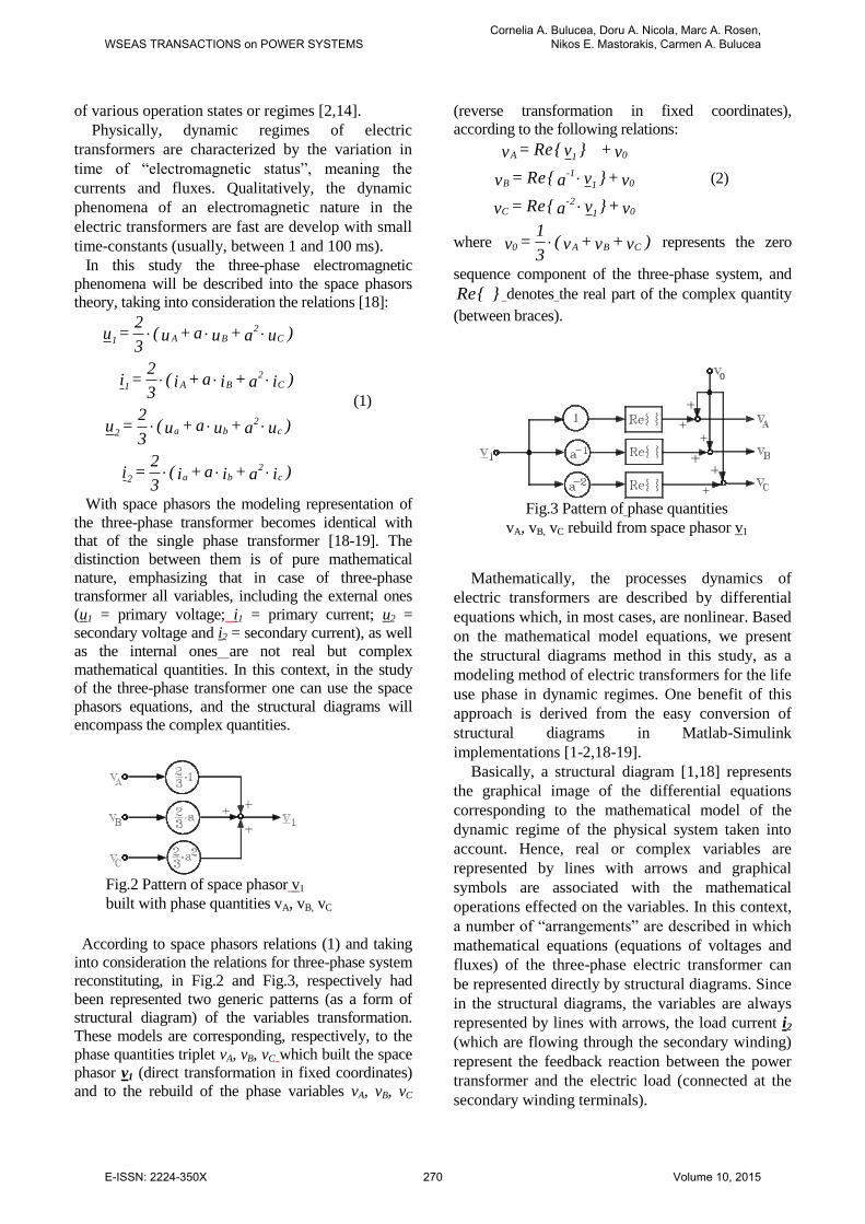
One can obtain a linear model under the
assumption that the ferromagnetic core
magnetization characteristic )if( = 1u can be
approximated by a straight line. Hence, for the case
of a linear model, the transformer ferromagnetic
core is considered as non-saturated, and one can
apply the principle of effects super-position, taking
into consideration the main cyclical inductance of
the transformer primary. Consequently, the
structural diagram of linear electromagnetic pattern
of three-phase transformer is depicted as in Fig. 4.
The three-phase transformer non-linear model
takes into consideration the non-linear dependence
between the main fascicular magnetic flux and the
magnetizing current. On a broader front, the
magnetizing characteristic of the transformer
ferromagnetic core has a non-linear trait. Actually,
the magnetizing curve )if( = 1u is obtained by
testing points and in the literature one can find it in
tabular form.
Fig. 4 Structural diagram with space phasors of three-
phase transformer linear model
For each value of the useful fascicular flux u,
the main magnetic flux u1 (through the surface
delimited by all turns w1 of primary phase winding)
is given by u1u1 w = . Moreover, neglecting the
losses in the transformer ferromagnetic core, the
total useful flux space phasor u1
and the
magnetizing current space phasor 'i + i = i211 are
collinear. So they can be mathematically translated
WSEAS TRANSACTIONS on POWER SYSTEMSCornelia A. Bulucea, Doru A. Nicola, Marc A. Rosen,
Nikos E. Mastorakis, Carmen A. Bulucea
E-ISSN: 2224-350X 271 Volume 10, 2015
by the following relation:
|i|
i|| =
|i|
i =
||1
1
u1u1
1
1
u1
u1
(5)
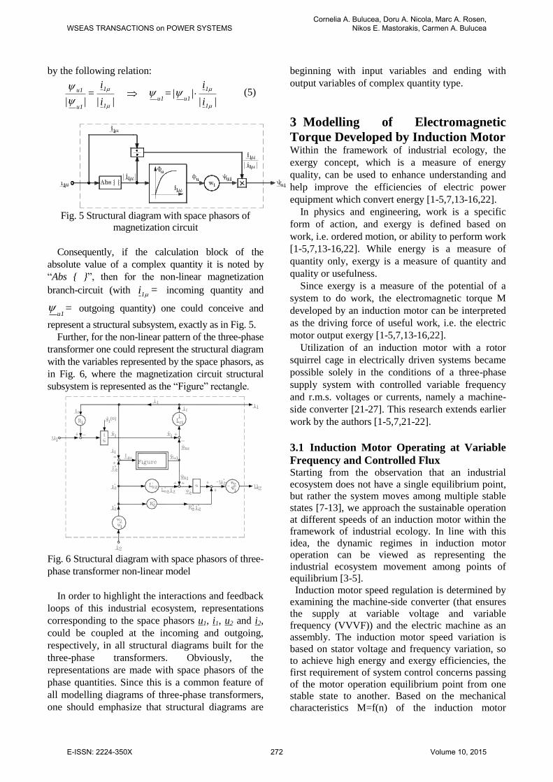
Fig. 5 Structural diagram with space phasors of
magnetization circuit
Consequently, if the calculation block of the
absolute value of a complex quantity it is noted by
“Abs { }”, then for the non-linear magnetization
branch-circuit (with = i1 incoming quantity and
= u1
outgoing quantity) one could conceive and
represent a structural subsystem, exactly as in Fig. 5.
Further, for the non-linear pattern of the three-phase
transformer one could represent the structural diagram
with the variables represented by the space phasors, as
in Fig. 6, where the magnetization circuit structural
subsystem is represented as the “Figure” rectangle.
Fig. 6 Structural diagram with space phasors of three-
phase transformer non-linear model
In order to highlight the interactions and feedback
loops of this industrial ecosystem, representations
corresponding to the space phasors u1, i1, u2 and i2,
could be coupled at the incoming and outgoing,
respectively, in all structural diagrams built for the
three-phase transformers. Obviously, the
representations are made with space phasors of the
phase quantities. Since this is a common feature of
all modelling diagrams of three-phase transformers,
one should emphasize that structural diagrams are
beginning with input variables and ending with
output variables of complex quantity type.
3 Modelling of Electromagnetic
Torque Developed by Induction Motor Within the framework of industrial ecology, the
exergy concept, which is a measure of energy
quality, can be used to enhance understanding and
help improve the efficiencies of electric power
equipment which convert energy [1-5,7,13-16,22].
In physics and engineering, work is a specific
form of action, and exergy is defined based on
work, i.e. ordered motion, or ability to perform work
[1-5,7,13-16,22]. While energy is a measure of
quantity only, exergy is a measure of quantity and
quality or usefulness.
Since exergy is a measure of the potential of a
system to do work, the electromagnetic torque M
developed by an induction motor can be interpreted
as the driving force of useful work, i.e. the electric
motor output exergy [1-5,7,13-16,22].
Utilization of an induction motor with a rotor
squirrel cage in electrically driven systems became
possible solely in the conditions of a three-phase
supply system with controlled variable frequency
and r.m.s. voltages or currents, namely a machine-
side converter [21-27]. This research extends earlier
work by the authors [1-5,7,21-22].
3.1 Induction Motor Operating at Variable
Frequency and Controlled Flux Starting from the observation that an industrial
ecosystem does not have a single equilibrium point,
but rather the system moves among multiple stable
states [7-13], we approach the sustainable operation
at different speeds of an induction motor within the
framework of industrial ecology. In line with this
idea, the dynamic regimes in induction motor
operation can be viewed as representing the
industrial ecosystem movement among points of
equilibrium [3-5].
Induction motor speed regulation is determined by
examining the machine-side converter (that ensures
the supply at variable voltage and variable
frequency (VVVF)) and the electric machine as an
assembly. The induction motor speed variation is
based on stator voltage and frequency variation, so
to achieve high energy and exergy efficiencies, the
first requirement of system control concerns passing
of the motor operation equilibrium point from one
stable state to another. Based on the mechanical
characteristics M=f(n) of the induction motor
WSEAS TRANSACTIONS on POWER SYSTEMSCornelia A. Bulucea, Doru A. Nicola, Marc A. Rosen,
Nikos E. Mastorakis, Carmen A. Bulucea
E-ISSN: 2224-350X 272 Volume 10, 2015
operation at variable speed [3-5] we highlight an
analogy between this electrical power system and an
ecosystem: appropriate technical system control
must be achieved for reducing exergy destruction
when the equilibrium point passes from one stable
state (represented by the operation point on a certain
mechanical characteristic) to another stable state
(with the operation point on another mechanical
characteristic). This observation implies the system
control needs to be assessed next, taking into
consideration the induction motor operating at
controlled flux and the machine-side converter (that
ensures the supply at variable voltage and variable
frequency) as a whole.
The operation at variable frequency with controlled
flux is preceded for induction motors in drive
systems with vectorial control [1,7,21-27]. The
vectorial regulation and control method is based on
space phasor theory, taking into consideration the
control of both the flux and the induction machine
electromagnetic torque M. In principle, the stator
current space phasor is decomposed into two
perpendicular components (a flux component and a
torque component) which are separately controlled.
One could analyze the permanent harmonics regime
of variable frequency operation with controlled
stator flux, controlled useful flux or controlled rotor
flux. As an example, we present the operation with
controlled stator flux [1,21].
The following relations can be derived for the
stator current components [21]:
R
L+
L
RL
-1=I
R
L
R
L+
L
RL
-1+
L=I
r
rr
rr
r
s
s
sy
r
rr
r
rr
rr
r
s
ss
ssx
(6)
The absolute value of the stator current can be
determined with the formula Is= (Isx2+Isy
2)
1/2.
Within an ecological framework, the
electromagnetic torque M is related to the system
output exergy. We can express M in complex
coordinates axes system (oriented on ψs) as
I3p =
=})jI+IIm{(3p=
=}IIm{3p = M
sys
ssysx
*
ss
(7)
Substituting Isy from (6), the torque relation
becomes
R
L+
L
RL
-13p=M
r
rr
rr
r
2
s
s
(8)
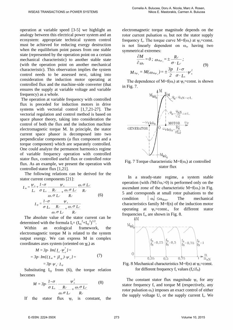
If the stator flux ψs is constant, the
electromagnetic torque magnitude depends on the
rotor current pulsation ωr but not the stator supply
frequency fs. The torque curve M=f(ωr) at ψs=const.
is not linearly dependent on ωr, having two
symmetrical extremes:
2
s
s
rkk
r
rrk
r
L
-1
2
3p=)M(=M
; L
R = ; 0 =
M
ss
s
(9)
The dependence of M=f(ωr) at ψs=const. is shown
in Fig. 7.
Fig. 7 Torque characteristic M=f(ωr) at controlled
stator flux
In a steady-state regime, a system stable
operation (with M/ωr>0) is performed only on the
ascendant zone of the characteristic M=f(ωr) in Fig.
5 and corresponds at small rotor pulsations to the
condition ωrωrkψs. The mechanical
characteristics family M=f(n) of the induction motor
operating at ψs=const., for different stator
frequencies fs, are shown in Fig. 8.
Fig. 8 Mechanical characteristics M=f(n) at ψs=const.
for different frequency fs values (fsfN)
The constant stator flux magnitude ψs for any
stator frequency fs and torque M (respectively, any
rotor pulsation ωr) imposes an exact control of either
the supply voltage Us or the supply current Is. We
WSEAS TRANSACTIONS on POWER SYSTEMSCornelia A. Bulucea, Doru A. Nicola, Marc A. Rosen,
Nikos E. Mastorakis, Carmen A. Bulucea
E-ISSN: 2224-350X 273 Volume 10, 2015
see again an analogy between this electrical system
and an ecosystem. An appropriate technical system
control must be achieved for reducing exergy
destruction when the equilibrium point passes from
one stable state (represented by the operation point
on a certain mechanical characteristic) to another
stable state (on another mechanical characteristic).
This observation implies the system control needs to
be assessed next.
One could notice in the permanent harmonic
regime among the fluxes Ψs , Ψu , Ψ'r and the
currents Is, I'r of any unsaturated induction machine,
electric and magnetic symmetry. Hence the
following operating relations apply:
j +I R = 0
IL + =
L
L + IL =
+ IL =
rrrr
rrur
rr
u
sss
usss
'''
'''
'
(10)
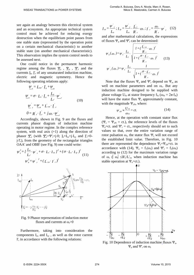
Accordingly, shown in Fig. 9 are the fluxes and
currents phasor diagram of induction machine
operating in motor regime. In the complex reference
system, with real axis (+1) along the direction of
phasor Ψ'r (with Ψ'r=Ψ'r+j0; Is=Isx+jIsy and I'r=0-
jI'r), from the geometry of the rectangular triangles
OAA' and OBB' (see Fig. 9) one could write:
)IL( + =
)IL( + ]IL + L
L[ =
rr
2
r
2 2
u
2
sys
2
sxsrr
u2
s
'''
'
(11)
Fig. 9 Phasor representation of induction motor
fluxes and currents at ωr>0
Furthermore, taking into consideration the
components Isx and Isy , as well as the rotor current
I'r in accordance with the following relations:
'
'
'
'
'''
r
r
r
rr
r
r
u
rsy
u
rsx
R = I ;
R
L
L = I ;
L = I (12)
and after mathematical calculations, the expressions
of fluxes Ψu and Ψ'r can be determined:
)R
L(+1
1
L
L = )(
)R
L(+1
)R
L(+1
L
L = )(
2
r
r
rs
u
srr
2
r
r
r
2
r
r
r
s
u
sru
'
'
'
'
'
'
'
(13)
Note that the fluxes Ψu and Ψ'r depend on Ψs, as
well on machine parameters and on ωr. But any
induction machine designed to be supplied with
phase voltage UN at stator frequency fN (ωN = 2πfN)
will have the stator flux Ψs approximately constant,
with the magnitude ΨsN, where:
ct. = U
N
N
sN
(14)
Hence, at the operation with constant stator flux
(Ψs = ΨsN = ct.), the reference levels of the fluxes
Ψu=ct. and Ψ'r = ct., respectively should set to such
values so that, over the entire variation range of
rotor pulsation ωr, the stator flux Ψs will not exceed
the established limit value. Therefore, in Fig. 10
there are represented the dependence Ψs=ΨsN=ct. in
accordance with (14), Ψu = f1(ωr) and Ψ'r = f2(ωr)
according to (12) for the maximum variation range
of ωr (ωrR'r/L'rσ when induction machine has
stable operation at Ψu=ct.).
Fig. 10 Dependence of induction machine fluxes Ψs,
Ψu and Ψ'r on ωr
WSEAS TRANSACTIONS on POWER SYSTEMSCornelia A. Bulucea, Doru A. Nicola, Marc A. Rosen,
Nikos E. Mastorakis, Carmen A. Bulucea
E-ISSN: 2224-350X 274 Volume 10, 2015
Based on the curves of Fig. 10 and the mentioned
relations the constant flux levels are determined:
)2
= ( ct. =
)L
L( + 1
1
L
L = )
L
R(f =
ct. =
)L
L( + 1
2
L
L = )
L
R(f =
ct. = =
u
r2
r
rs
u
s
r
r
2r
2
r
rs
u
s
r
r
1u
sNs
'
'
''
''
'
''
'
(15)
For these constant values of fluxes Ψs, Ψu and Ψ'r,
an exergetic analysis imposes the electromagnetic
torque characteristics M = f(ωr) and stator current
characteristics Is = f(ωr) are compared on the stable
operation intervals.
3.1.1 Electromagnetic Torques Comparison at
Ψs = ct., Ψu=ct. and Ψ'r = ct.
For the three subsequent cases, the electromagnetic
torque M has the following expressions:
a) When stator flux is constant Ψs = ct.:
2
s
s
k
rr
r
r
rr
k
L
-1
2
3p = M
L
R+
R
L
M2 = M
s
s
'
'
(16)
b) When useful flux is constant Ψu = ct.:
2
u
r
k
rr
r
r
rr
k
L
1
2
3p = M
L
R+
R
L
M2 = M
u
u
'
'
'
'
'
(17)
c) When rotor flux is constant Ψ'r = ct.:
'
'
r
2
r
r
R3p = M (18)
Moreover, according to the constant flux levels
(15), between the maximum torques MkΨs and MkΨu
the following recurrence relationship can be
demonstrated:
)L
L +
L
L(2
1 =
M
M
r
r
r
r
k
k
u
s
'
'
'
'
(19)
Also, since the electromagnetic torque is
interpreted as output exergy, based on the
observation Ψ'r = Ψu/2 = ct., at Ψ'r = ct. a
relationship for the electromagnetic torque M could
be useful within the exergetic analysis:
r
r
rk
R
LM = M
u
'
'
(20)
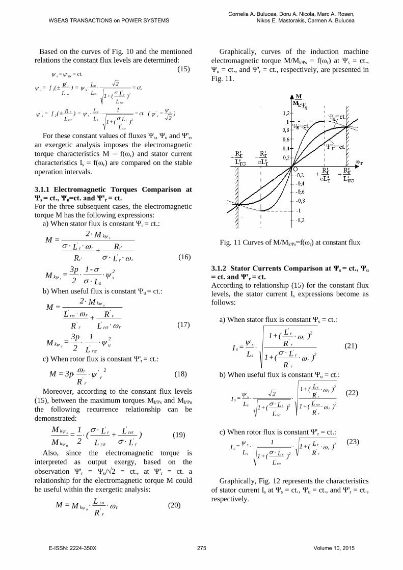
Graphically, curves of the induction machine
electromagnetic torque M/MkΨs = f(ωr) at Ψs = ct.,
Ψu = ct., and Ψ'r = ct., respectively, are presented in
Fig. 11.
Fig. 11 Curves of M/MkΨs=f(ωr) at constant flux
3.1.2 Stator Currents Comparison at Ψs = ct., Ψu
= ct. and Ψ'r = ct.
According to relationship (15) for the constant flux
levels, the stator current Is expressions become as
follows:
a) When stator flux is constant Ψs = ct.:
)R
L( + 1
)R
L( + 1
L = I
2
r
r
r
2
r
r
r
s
ss
'
'
'
'
(21)
b) When useful flux is constant Ψu = ct.:
)R
L( + 1
)R
L( + 1
)L
L( + 1
2
L = I
2
r
r
r
2
r
r
r
2
r
rs
ss
'
'
'
'
'
'
(22)
c) When rotor flux is constant Ψ'r = ct.:
)R
L( + 1
)L
L( + 1
1
L = I
2
r
r
r
2
r
rs
ss
'
'
'
'
(23)
Graphically, Fig. 12 represents the characteristics
of stator current Is at Ψs = ct., Ψu = ct., and Ψ'r = ct.,
respectively.
WSEAS TRANSACTIONS on POWER SYSTEMSCornelia A. Bulucea, Doru A. Nicola, Marc A. Rosen,
Nikos E. Mastorakis, Carmen A. Bulucea
E-ISSN: 2224-350X 275 Volume 10, 2015
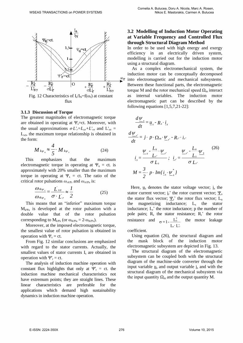
Fig. 12 Characteristics of Is/IN=f(ωr) at constant
flux
3.1.3 Discussion of Torque
The greatest magnitudes of electromagnetic torque
are obtained in operating at Ψs=ct. Moreover, with
the usual approximations σL'r=Lsσ+L'rσ and L'rσ =
Lsσ, the maximum torque relationship is obtained in
the form:
M5
4 M
su kk (24)
This emphasizes that the maximum
electromagnetic torque in operating at Ψu = ct. is
approximately with 20% smaller than the maximum
torque in operating at Ψs = ct. The ratio of the
critical rotor pulsations ωrkΨs and ωrkΨu is:
2
1
L
L =
r
r
rk
rk
u
s '
'
(25)
This means that an “inferior” maximum torque
MkΨu is developed at the rotor pulsation with a
double value that of the rotor pulsation
corresponding to MkΨs (or ωrkΨu = 2ωrkΨs).
Moreover, at the imposed electromagnetic torque,
the smallest value of rotor pulsation is obtained in
operation with Ψs = ct.
From Fig. 12 similar conclusions are emphasized
with regard to the stator currents. Actually, the
smallest values of stator currents Is are obtained in
operation with Ψ'r = ct.
The analysis of induction machine operation with
constant flux highlights that only at Ψ'r = ct. the
induction machine mechanical characteristics not
have extremum points; they are straight lines. These
linear characteristics are preferable for the
applications which demand high sustainability
dynamics in induction machine operation.
3.2 Modelling of Induction Motor Operating
at Variable Frequency and Controlled Flux
through Structural Diagram Method
In order to be used with high energy and exergy
efficiency in an electrically driven system,
modelling is carried out for the induction motor
using a structural diagram.
As a complex electromechanical system, the
induction motor can be conceptually decomposed
into electromagnetic and mechanical subsystems.
Between these functional parts, the electromagnetic
torque M and the rotor mechanical speed Ωm interact
as internal variables. The induction motor
electromagnetic part can be described by the
following equations [1,5,7,21-22]:
}iIm{p2
3 = M
L
L
L -
= i ; L
L
L -
= i
iR - pj = dt
d
iR - u = dt
d
*
ss
r
s
s
u
r
r
s
rr
u
s
s
rrrmr
sss
s
(26)
Here, us denotes the stator voltage vector; is the
stator current vector; ir’ the rotor current vector; s
the stator flux vector; r’ the rotor flux vector; Lu
the magnetizing inductance; Ls the stator
inductance; Lr’ the rotor inductance; p the number of
pole pairs; Rs the stator resistance; Rr’ the rotor
resistance and
'LL
L - 1 =
rs
2u
the motor leakage
coefficient.
Using equation (26), the structural diagram and
the mask block of the induction motor
electromagnetic subsystem are depicted in Fig. 13.
The structural diagram of the electromagnetic
subsystem can be coupled both with the structural
diagram of the machine-side converter through the
input variable us and output variable is and with the
structural diagram of the mechanical subsystem via
the input quantity Ωm and the output quantity M.
WSEAS TRANSACTIONS on POWER SYSTEMSCornelia A. Bulucea, Doru A. Nicola, Marc A. Rosen,
Nikos E. Mastorakis, Carmen A. Bulucea
E-ISSN: 2224-350X 276 Volume 10, 2015
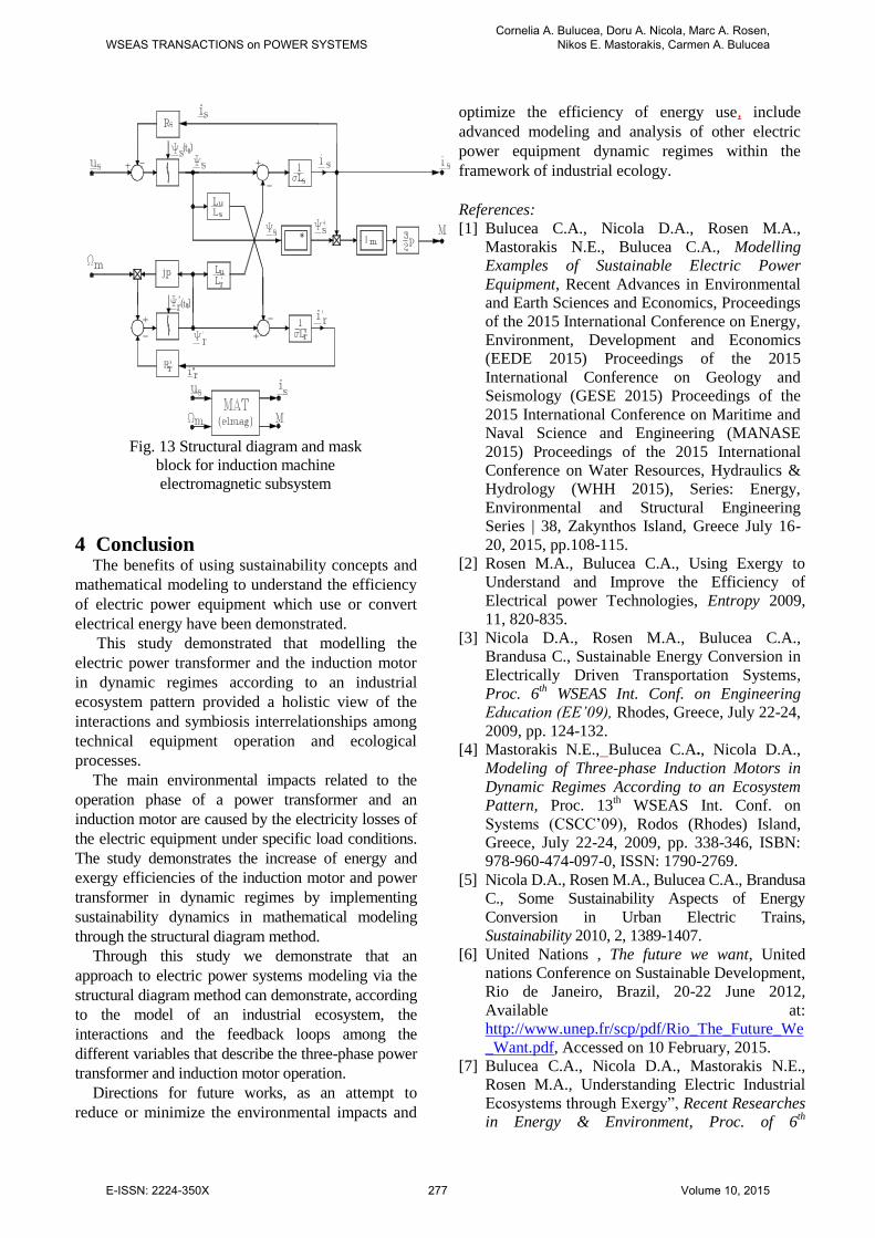
Fig. 13 Structural diagram and mask
block for induction machine
electromagnetic subsystem
4 Conclusion The benefits of using sustainability concepts and
mathematical modeling to understand the efficiency
of electric power equipment which use or convert
electrical energy have been demonstrated.
This study demonstrated that modelling the
electric power transformer and the induction motor
in dynamic regimes according to an industrial
ecosystem pattern provided a holistic view of the
interactions and symbiosis interrelationships among
technical equipment operation and ecological
processes.
The main environmental impacts related to the
operation phase of a power transformer and an
induction motor are caused by the electricity losses of
the electric equipment under specific load conditions.
The study demonstrates the increase of energy and
exergy efficiencies of the induction motor and power
transformer in dynamic regimes by implementing
sustainability dynamics in mathematical modeling
through the structural diagram method.
Through this study we demonstrate that an
approach to electric power systems modeling via the
structural diagram method can demonstrate, according
to the model of an industrial ecosystem, the
interactions and the feedback loops among the
different variables that describe the three-phase power
transformer and induction motor operation.
Directions for future works, as an attempt to
reduce or minimize the environmental impacts and
optimize the efficiency of energy use, include
advanced modeling and analysis of other electric
power equipment dynamic regimes within the
framework of industrial ecology.
References:
[1] Bulucea C.A., Nicola D.A., Rosen M.A.,
Mastorakis N.E., Bulucea C.A., Modelling
Examples of Sustainable Electric Power
Equipment, Recent Advances in Environmental
and Earth Sciences and Economics, Proceedings
of the 2015 International Conference on Energy,
Environment, Development and Economics
(EEDE 2015) Proceedings of the 2015
International Conference on Geology and
Seismology (GESE 2015) Proceedings of the
2015 International Conference on Maritime and
Naval Science and Engineering (MANASE
2015) Proceedings of the 2015 International
Conference on Water Resources, Hydraulics &
Hydrology (WHH 2015), Series: Energy,
Environmental and Structural Engineering
Series | 38, Zakynthos Island, Greece July 16-
20, 2015, pp.108-115.
[2] Rosen M.A., Bulucea C.A., Using Exergy to
Understand and Improve the Efficiency of
Electrical power Technologies, Entropy 2009,
11, 820-835.
[3] Nicola D.A., Rosen M.A., Bulucea C.A.,
Brandusa C., Sustainable Energy Conversion in
Electrically Driven Transportation Systems,
Proc. 6th WSEAS Int. Conf. on Engineering
Education (EE’09), Rhodes, Greece, July 22-24,
2009, pp. 124-132.
[4] Mastorakis N.E., Bulucea C.A., Nicola D.A.,
Modeling of Three-phase Induction Motors in
Dynamic Regimes According to an Ecosystem
Pattern, Proc. 13th WSEAS Int. Conf. on
Systems (CSCC’09), Rodos (Rhodes) Island,
Greece, July 22-24, 2009, pp. 338-346, ISBN:
978-960-474-097-0, ISSN: 1790-2769.
[5] Nicola D.A., Rosen M.A., Bulucea C.A., Brandusa
C., Some Sustainability Aspects of Energy
Conversion in Urban Electric Trains,
Sustainability 2010, 2, 1389-1407.
[6] United Nations , The future we want, United
nations Conference on Sustainable Development,
Rio de Janeiro, Brazil, 20-22 June 2012,
Available at:
http://www.unep.fr/scp/pdf/Rio_The_Future_We
_Want.pdf, Accessed on 10 February, 2015.
[7] Bulucea C.A., Nicola D.A., Mastorakis N.E.,
Rosen M.A., Understanding Electric Industrial
Ecosystems through Exergy”, Recent Researches
in Energy & Environment, Proc. of 6th
WSEAS TRANSACTIONS on POWER SYSTEMSCornelia A. Bulucea, Doru A. Nicola, Marc A. Rosen,
Nikos E. Mastorakis, Carmen A. Bulucea
E-ISSN: 2224-350X 277 Volume 10, 2015
IASME/WSEAS International Conference on
Energy & Environment, University of
Cambridge, Cambridge, UK, February 23-25,
2011, pp. 182-191.
[8] Graedel T.E.., On the Concept of Industrial
Ecology, Annual Review of Energy and the
Environment, Vol. 21, November 1996, 69-98.
[9] Ayres R.U., Industrial Metabolism, In Ausubel
J.H., and Sladovich H.E. (eds): Technology and
Environment, pp. 23-49, National Academy
Press, Washington, 1989.
[10] Graedel T.E., Allenby B.R., Industrial
Ecology, Prentice Hall, New Jersey, 1995.
[11] Allenby B.R., Industrial Ecology: Policy
Framework and Implementation. Prentice-Hall,
New Jersey, 1999.
[12] Allenby B.R., Industrial Ecology,
Information and Sustainability, Foresight:
Journal of Future Studies, Strategic Thinking
and Policy, Vol. 2, No. 2, 2000, 163-171.
[13] Dincer I., Rosen M.A., Exergy: Energy,
Environment and Sustainable Development, 2d
ed., Elsevier: Oxford, UK, 2013.
[14] Rosen M.A., A Concise Review of Energy-
Based Economic Methods, Proc. 3rd
IASME/WSEAS Int. Conf. on Energy &
Environment, Cambridge, UK, Feb. 23-25, 2008,
136-142.
[15] Wall G., Gong M., On Exergy and
Sustainable Development, Part I: Conditions and
Concepts, Exergy: An International Journal,
Vol. 1, No. 3, 2001, 128-145.
[16] Wall G., Exergy tools, Proc. Inst.
Mechanical Engineers, Part A: J. Power and
Energy, Vol. 217, 2003, 125-136.
[17] LCA study of current transformers,
DANTES project co-funded by the EU Life-
Environment Program, Available at: at:
http://www.dantes.info/Publications/Publication
-
doc/DANTES%20ABB%20LCA%20study%20
of%20instrument%20transformers.pdf,
Accessed on 14 March 2015.
[18] Nicola D.A., Bulucea C.A., Electrotechnics,
Electrical Equipment and Machines, Vol. II
“Electrical Equipment”, SITECH Publishing
House, Craiova, 2005.
[19] Bulucea C.A., Nicola D.A., Mastorakis
N.E., Cismaru D.C., Modelling of Electrical
Transformers in Dynamic Regimes, Recent
Advances in Electric Power Systems, High
Voltages, Electric Machines, Proc. 9th
WSEAS/IASME Int. Conf. on Electric Power
Systems, High Voltages, Electric Machines,
University of Genova, Genova, Italy, October
17-19, 2009, 188-195.
[20] Bulucea C.A., Nicola D.A., Mastorakis N.E.,
Dondon Ph.., Bulucea C.A., Cismaru D.C.,
Fostering the Sustainability of Power
Transformers, Recent Researches in
Environmental & Geological Sciences, Proc. of
7th WSEAS International Conference on Energy
and Environment (EE’12), Kos Island, Greece,
July 14-17, 2012, pp. 72-81.
[21] Nicola D.A., Electric Traction (Tractiune
electrica), Universitaria Publishing House,
Craiova, Romania, 2012.
[22] Nicola D.A., Rosen M.A., Bulucea C.A.,
Cismaru D.C., Some Aspects of Sustainable
Energy Conversion in Electric Railway Vehicles
with Traction Induction Motors, Recent
Advances in Systems Science: Proc. 17th Int.
Conf. on Systems, Rhodes Island, Greece, July
16-19, 2013, pp. 44-53.
[23] Chatelain, Machines électriques (Electrical
Machines), PPUR, Lausanne, 1989.
[24] Kaller R., Allenbach J.M., Traction
Electrique (Electrical Traction), Vol. 1-2,
PPUR, Lausanne, 1995.
[25] Buhler H., Reglage de Systemes
d’Electronique de Puissance, Vol. I, PPUR,
Lausanne, 1997.
[26] Potter S., Exploring Approaches Towards a
Sustainable Transport System, International
Journal of Sustainable Transportation, Vol. 1,
Issue. 2, 2007, 115-131.
[27] MacHaris C., Van Mierlo J., Van Den
Bossche P., Combining Intermodal Transport
with Electric Vehicles: Towards More
Sustainable Solutions, Transportation Planning
and Technology, Vol. 30, Issue 2-3, 2007, 311-
323.
WSEAS TRANSACTIONS on POWER SYSTEMSCornelia A. Bulucea, Doru A. Nicola, Marc A. Rosen,
Nikos E. Mastorakis, Carmen A. Bulucea
E-ISSN: 2224-350X 278 Volume 10, 2015