Embed Size (px)
Citation preview
Answers for life.
SOMATOM ScopePower configuration Datasheet for syngo CT VC28
www.siemens.com/somatom-scope
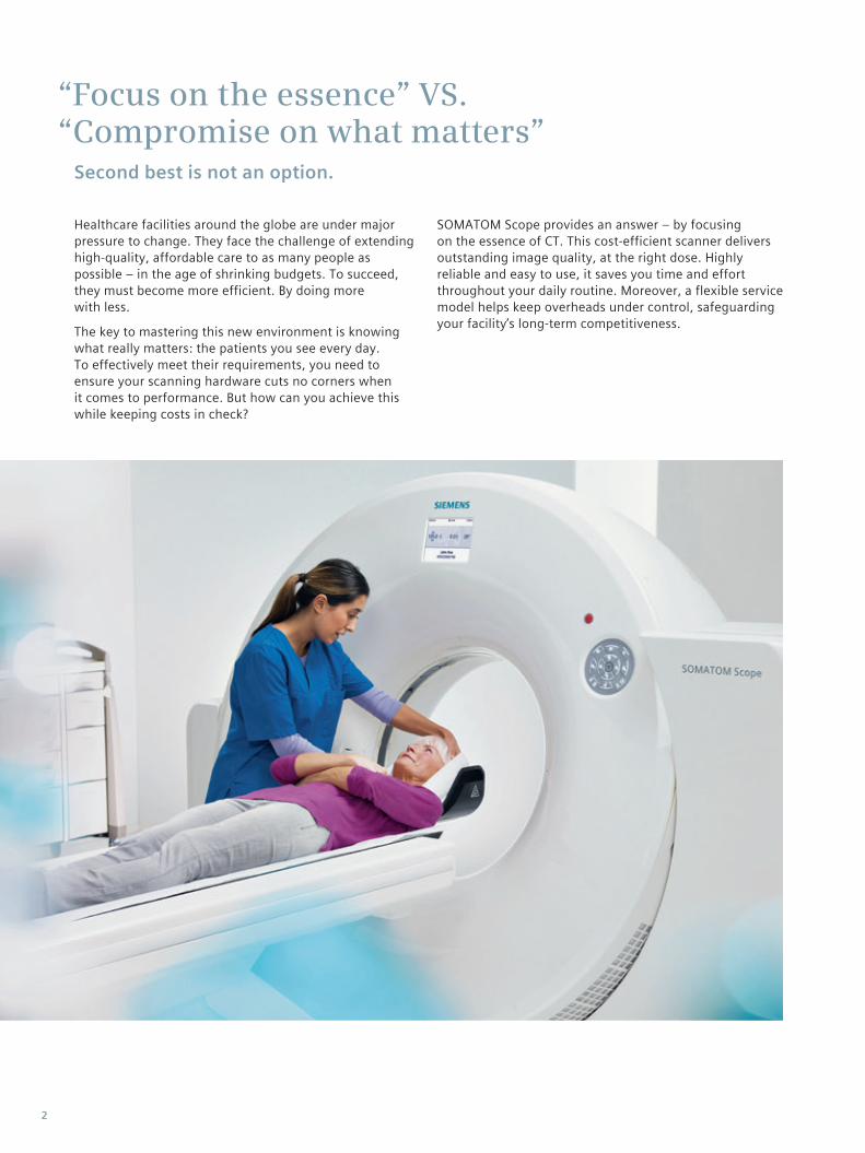
Healthcare facilities around the globe are under major pressure to change. They face the challenge of extending high-quality, affordable care to as many people as possible – in the age of shrinking budgets. To succeed, they must become more efficient. By doing more with less.
The key to mastering this new environment is knowing what really matters: the patients you see every day. To effectively meet their requirements, you need to ensure your scanning hardware cuts no corners when it comes to per formance. But how can you achieve this while keeping costs in check?
SOMATOM Scope provides an answer – by focusing on the essence of CT. This cost-efficient scanner delivers outstanding image quality, at the right dose. Highly reliable and easy to use, it saves you time and effort throughout your daily routine. Moreover, a flexible service model helps keep overheads under control, safeguarding your facility’s long-term competitiveness.
“Focus on the essence” VS. “Compromise on what matters” Second best is not an option.
2
Highlights
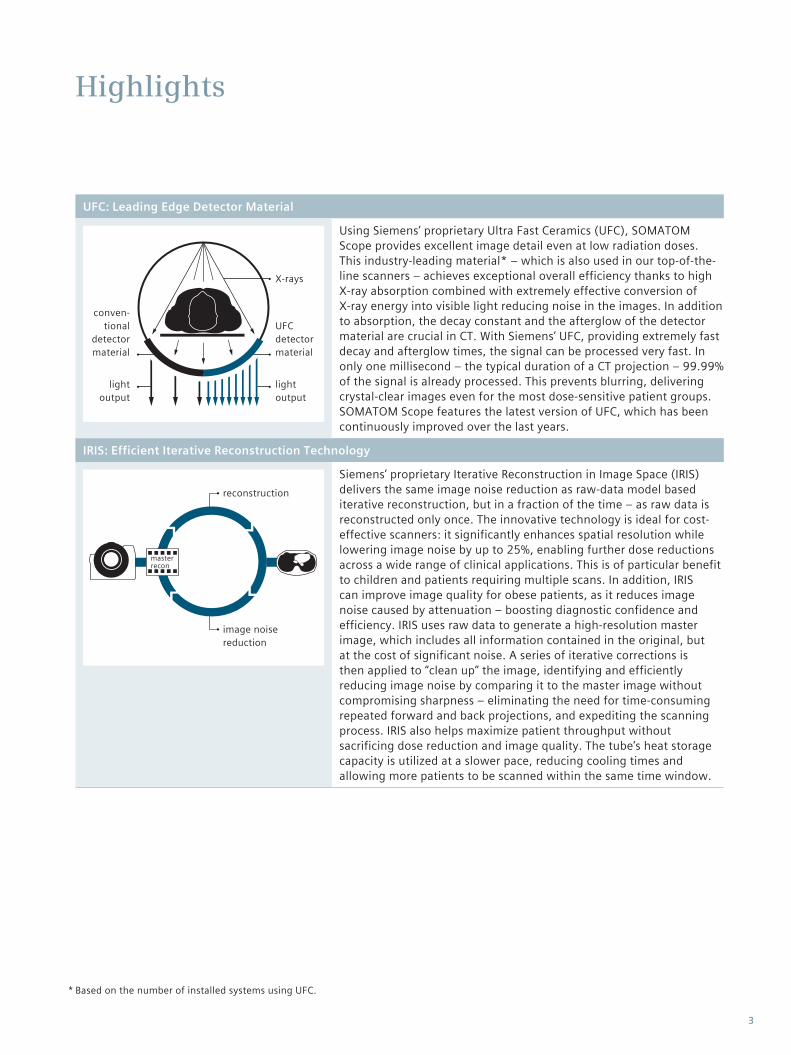
UFC: Leading Edge Detector Material
X-rays
lightoutput
lightoutput
UFC detector material
conven- tional
detectormaterial
Using Siemens’ proprietary Ultra Fast Ceramics (UFC), SOMATOM Scope provides excellent image detail even at low radiation doses. This industry-leading material* – which is also used in our top-of-the-line scanners – achieves exceptional overall efficiency thanks to high X-ray absorption combined with extremely effective conversion of X-ray energy into visible light reducing noise in the images. In addition to absorption, the decay constant and the afterglow of the detector material are crucial in CT. With Siemens’ UFC, providing extremely fast decay and afterglow times, the signal can be processed very fast. In only one millisecond – the typical duration of a CT projection – 99.99% of the signal is already processed. This prevents blurring, delivering crystal-clear images even for the most dose-sensitive patient groups. SOMATOM Scope features the latest version of UFC, which has been continuously improved over the last years.
IRIS: Efficient Iterative Reconstruction Technology
reconstruction
image noise reduction
master recon
Siemens’ proprietary Iterative Reconstruction in Image Space (IRIS) delivers the same image noise reduction as raw-data model based iterative reconstruction, but in a fraction of the time – as raw data is reconstructed only once. The innovative technology is ideal for cost-effective scanners: it significantly enhances spatial resolution while lowering image noise by up to 25%, enabling further dose reductions across a wide range of clinical applications. This is of particular benefit to children and patients requiring multiple scans. In addition, IRIS can improve image quality for obese patients, as it reduces image noise caused by attenuation – boosting diagnostic confidence and efficiency. IRIS uses raw data to generate a high-resolution master image, which includes all information contained in the original, but at the cost of significant noise. A series of iterative corrections is then applied to “clean up” the image, identifying and efficiently reducing image noise by comparing it to the master image without compromising sharpness – eliminating the need for time-consuming repeated forward and back projections, and expediting the scanning process. IRIS also helps maximize patient throughput without sacrificing dose reduction and image quality. The tube’s heat storage capacity is utilized at a slower pace, reducing cooling times and allowing more patients to be scanned within the same time window.
Based on the number of installed systems using UFC.*
3
Highlights
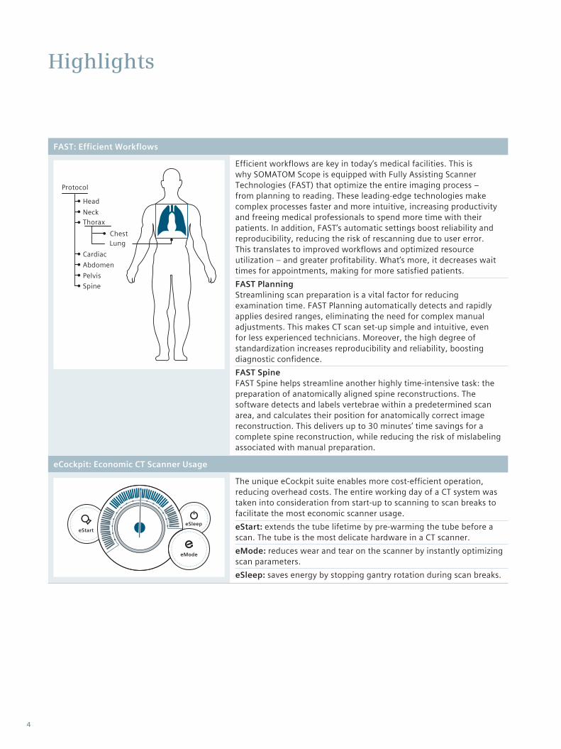
FAST: Efficient Workflows
Protocol
HeadNeckThorax
CardiacAbdomenPelvisSpine
ChestLung
Efficient workflows are key in today’s medical facilities. This is why SOMATOM Scope is equipped with Fully Assisting Scanner Technologies (FAST) that optimize the entire imaging process – from planning to reading. These leading-edge technologies make complex processes faster and more intuitive, increasing productivity and freeing medical professionals to spend more time with their patients. In addition, FAST’s automatic settings boost reliability and reproducibility, reducing the risk of rescanning due to user error. This translates to improved workflows and optimized resource utilization – and greater profitability. What’s more, it decreases wait times for appointments, making for more satisfied patients.FAST PlanningStreamlining scan preparation is a vital factor for reducing examination time. FAST Planning automatically detects and rapidly applies desired ranges, eliminating the need for complex manual adjustments. This makes CT scan set-up simple and intuitive, even for less experienced technicians. Moreover, the high degree of standardization increases reproducibility and reliability, boosting diagnostic confidence.FAST SpineFAST Spine helps streamline another highly time-intensive task: the preparation of anatomically aligned spine reconstructions. The software detects and labels vertebrae within a predetermined scan area, and calculates their position for anatomically correct image reconstruction. This delivers up to 30 minutes’ time savings for a complete spine reconstruction, while reducing the risk of mislabeling associated with manual preparation.
eCockpit: Economic CT Scanner Usage
eStarteSleep
eMode
The unique eCockpit suite enables more cost-efficient operation, reducing overhead costs. The entire working day of a CT system was taken into consideration from start-up to scanning to scan breaks to facilitate the most economic scanner usage.eStart: extends the tube lifetime by pre-warming the tube before a scan. The tube is the most delicate hardware in a CT scanner.eMode: reduces wear and tear on the scanner by instantly optimizing scan parameters.eSleep: saves energy by stopping gantry rotation during scan breaks.
4
System Configuration
Standard system hardware
0.6, 1.0, 1.5 s rotation timeMultislice UFC (Ultra Fast Ceramic) detector70 cm gantry with ±30° tilt82 KW max. equivalent generator power (with IRIS)DURA 422 MV High performance liquid bearing X-ray tubeCT patient table (200 kg / 440 lbs table load)
Optional system hardware
0.5 s rotation time*Recon PlusPatient table foot switchPatient table extensionAdditional 19” (48 cm) flat screen monitorDual 19” (48 cm) flat screen monitor with dual display functionalityTable cover paper dispenser
Standard workplace
syngo® Scope one console19” (48 cm) flat screen monitorCD/DVD storage
Standard system software
syngo Examinationsyngo Viewingsyngo Filmingsyngo Archiving & Networksyngo Service SolutionImage FilterSureView™Video Capture and Editing ToolScan Protocol Assistantsyngo 3D Real Time MPRsyngo 3D SSD (Surface Shaded Display)syngo Volume Calculationsyngo VRT (Volume Rendering Technique)CT-AngiographyVessel analysis with Automated Bone RemovalWorkStream4D™ (direct 3D-recon)syngo Dynamic EvaluationAdaptive Signal Boost
Standard FAST applications
FAST PlanningFAST Contact
Optional FAST applications
FAST Spine
Standard CARE applications
IRIS (Iterative Reconstruction in Image Space)CARE FilterCARE Bolus CTCARE TopoCARE Dose4DCARE Dose Configurator
Optional CARE applications
CARE Contrast CTECG-pulsing CARE Vision CT with HandCARE™
Included in syngo HeartView CT*
5
System Configuration
Optional systemapplications
Extended FoV (Field of View)syngo Expert-isyngo Dental CTsyngo Osteo CTsyngo Pulmo CTsyngo Fly Throughsyngo Body Perfusion CTsyngo Volume Perfusion Neuro CTsyngo Neuro DSA CT (Digital Subtraction Angiography)syngo CT Oncologysyngo Image Fusion CTsyngo CT Colonography CTsyngo CT Colonography CT PEVsyngo HeartView CT (including ECG-pulsing)syngo Calcium Scoring CT
Optionalapplications for CT-guided intervention
Advanced InterventionCARE Vision CT with HandCARE™
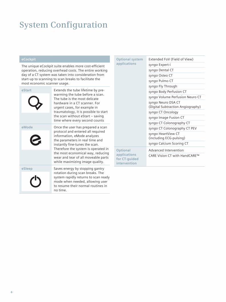
eCockpit
The unique eCockpit suite enables more cost-efficient operation, reducing overhead costs. The entire working day of a CT system was taken into consideration from start-up to scanning to scan breaks to facilitate the most economic scanner usage.
eStart Extends the tube lifetime by pre-warming the tube before a scan. The tube is the most delicate hardware in a CT scanner. For urgent cases, for example in traumatology, it is possible to start the scan without eStart – saving time where every second counts
eMode Once the user has prepared a scan protocol and entered all required information, eMode analyzes the parameters in real time and instantly fine-tunes the scan. Therefore the system is operated in the most economical way, reducing wear and tear of all moveable parts while maximizing image quality.
eSleep Saves energy by stopping gantry rotation during scan breaks. The system rapidly returns to scan ready mode when needed, allowing user to resume their normal routines in no time.
6
System Hardware
Optional*
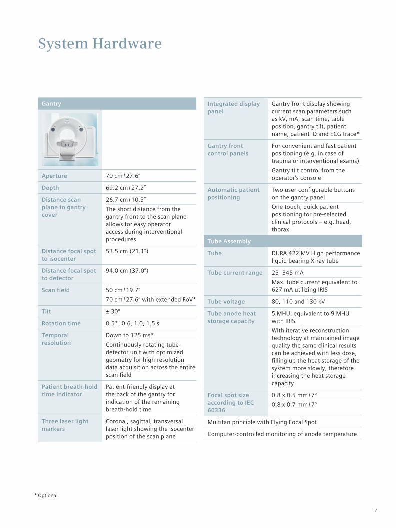
Gantry
Aperture 70 cm / 27.6”
Depth 69.2 cm / 27.2”
Distance scan plane to gantry cover
26.7 cm / 10.5”The short distance from the gantry front to the scan plane allows for easy operator access during interventional procedures
Distance focal spot to isocenter
53.5 cm (21.1”)
Distance focal spot to detector
94.0 cm (37.0”)
Scan field 50 cm / 19.7”70 cm / 27.6” with extended FoV*
Tilt ± 30°
Rotation time 0.5*, 0.6, 1.0, 1.5 s
Temporal resolution
Down to 125 ms*Continuously rotating tube-detector unit with optimized geometry for high-resolution data acquisition across the entire scan field
Patient breath-hold time indicator
Patient-friendly display at the back of the gantry for indication of the remaining breath-hold time
Three laser light markers
Coronal, sagittal, transversal laser light showing the isocenter position of the scan plane
Integrated display panel
Gantry front display showing current scan parameters such as kV, mA, scan time, table position, gantry tilt, patient name, patient ID and ECG trace*
Gantry front control panels
For convenient and fast patient positioning (e.g. in case of trauma or interventional exams)Gantry tilt control from the operator’s console
Automatic patient positioning
Two user-configurable buttons on the gantry panelOne touch, quick patient positioning for pre-selected clinical protocols – e.g. head, thorax
Tube Assembly
Tube DURA 422 MV High performance liquid bearing X-ray tube
Tube current range 25–345 mAMax. tube current equivalent to 627 mA utilizing IRIS
Tube voltage 80, 110 and 130 kV
Tube anode heat storage capacity
5 MHU; equivalent to 9 MHU with IRISWith iterative reconstruction technology at maintained image quality the same clinical results can be achieved with less dose, filling up the heat storage of the system more slowly, therefore increasing the heat storage capacity
Focal spot size according to IEC 60336
0.8 x 0.5 mm / 7°0.8 x 0.7 mm / 7°
Multifan principle with Flying Focal Spot
Computer-controlled monitoring of anode temperature
7
System Hardware
Generator
Max. power 50 kW; equivalent to 82 kW with IRIS
Data Acquisition System
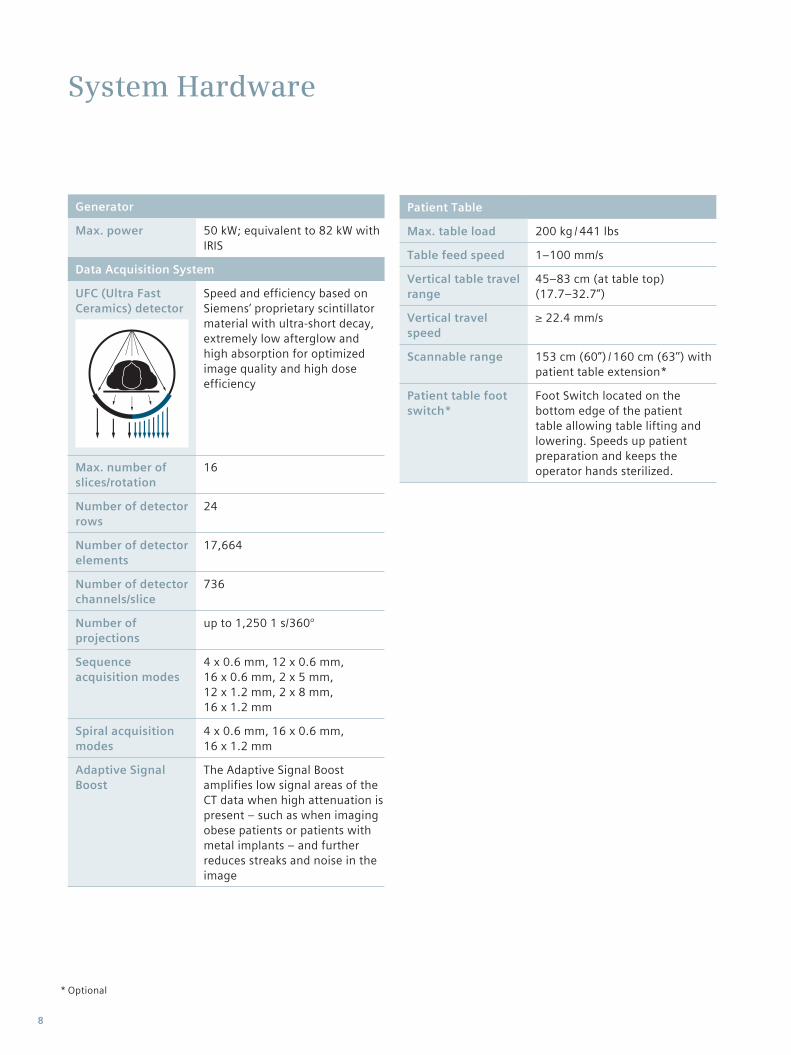
UFC (Ultra Fast Ceramics) detector
Speed and efficiency based on Siemens‘ proprietary scintillator material with ultra-short decay, extremely low afterglow and high absorption for optimized image quality and high dose efficiency
Max. number of slices/rotation
16
Number of detector rows
24
Number of detector elements
17,664
Number of detector channels/slice
736
Number of projections
up to 1,250 1 s/360°
Sequence acquisition modes
4 x 0.6 mm, 12 x 0.6 mm, 16 x 0.6 mm, 2 x 5 mm, 12 x 1.2 mm, 2 x 8 mm, 16 x 1.2 mm
Spiral acquisition modes
4 x 0.6 mm, 16 x 0.6 mm, 16 x 1.2 mm
Adaptive Signal Boost
The Adaptive Signal Boost amplifies low signal areas of the CT data when high attenuation is present – such as when imaging obese patients or patients with metal implants – and further reduces streaks and noise in the image
Patient Table
Max. table load 200 kg / 441 lbs
Table feed speed 1–100 mm/s
Vertical table travel range
45–83 cm (at table top) (17.7–32.7”)
Vertical travel speed
≥ 22.4 mm/s
Scannable range 153 cm (60”) / 160 cm (63’’) with patient table extension*
Patient table foot switch*
Foot Switch located on the bottom edge of the patient table allowing table lifting and lowering. Speeds up patient preparation and keeps the operator hands sterilized.
Optional*
8
OptionalOr equivalentOptional. Additional monitor for replication of primary monitor at remote location. Distance from host up to 30 m.Optional. Dual monitor enables the simultaneous display of two scans on two monitors within the 3D task card, ideally used for comparison of follow-up studies or native and contrast-enhanced scans.
* **
*******
Workplace Overview: syngo Scope one console
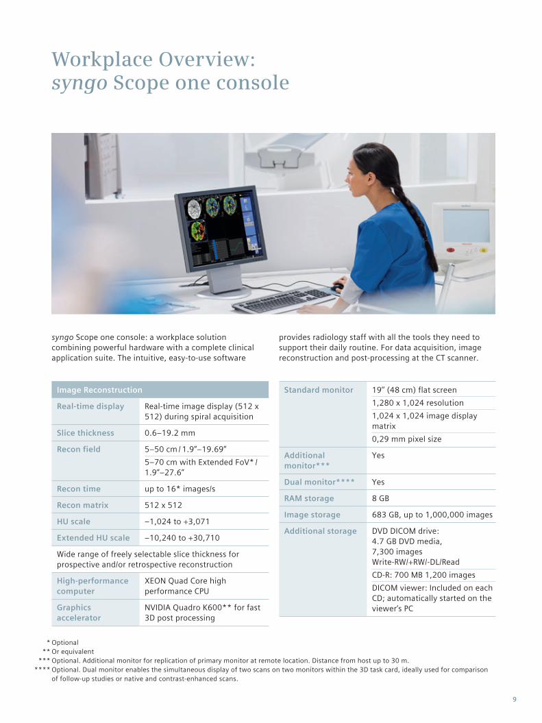
syngo Scope one console: a workplace solution combining powerful hardware with a complete clinical application suite. The intuitive, easy-to-use software
Image Reconstruction
Real-time display Real-time image display (512 x 512) during spiral acquisition
Slice thickness 0.6–19.2 mm
Recon field 5–50 cm / 1.9”–19.69” 5–70 cm with Extended FoV* / 1.9”–27.6”
Recon time up to 16* images/s
Recon matrix 512 x 512
HU scale –1,024 to +3,071
Extended HU scale –10,240 to +30,710
Wide range of freely selectable slice thickness for prospective and/or retrospective reconstruction
High-performance computer
XEON Quad Core high performance CPU
Graphics accelerator
NVIDIA Quadro K600** for fast 3D post processing
Standard monitor 19’’ (48 cm) flat screen1,280 x 1,024 resolution1,024 x 1,024 image display matrix0,29 mm pixel size
Additional monitor***
Yes
Dual monitor**** Yes
RAM storage 8 GB
Image storage 683 GB, up to 1,000,000 images
Additional storage DVD DICOM drive: 4.7 GB DVD media, 7,300 images Write-RW/+RW/-DL/ReadCD-R: 700 MB 1,200 imagesDICOM viewer: Included on each CD; automatically started on the viewer’s PC
provides radiology staff with all the tools they need to support their daily routine. For data acquisition, image reconstruction and post-processing at the CT scanner.
9
Standard System Software: syngo Examinations
Scan Protocol Assistant
Up to 10,000 protocols can be edited, modified, and storedEasy and intuitive way to change and manage scan protocols
Automatic Patient Positioning
Two user-configurable buttons on the gantry panelOne touch, quick patient positioning for preselected clinical protocols – e.g. head, thorax
Topogram
Length 128–1,500 mm (5–59”)
Scan times 2.08–15.8 s
Views a.p., p.a., lateral
Real-time topogram
Manual interruption possible once desired anatomy has been imaged
Patient Communication
Integrated patient intercom
Automatic Patient Instruction (API)
Freely recordable30 API text pairsPresets in nine languages available
Sequence Acquisition
Reconstructed slice widths
0.6, 1.2, 2.4, 3.6, 4.8, 5.0, 8.0,9.6, 10.0, 16.0, 19.2 mm
Partial scan times (240°)
0.33*, 0.4 s
No. of uninter-rupted scans per range
99
No. of ranges in autorange
8
Scan times (full scan)
0.5*, 0.6, 1.0, 1.5 s
Scan range max. 160 cm (63”)
Acquisition with or without table feed
Automatic clustering of scans
Dynamic Multiscan Multiple (continuous) sequence scanning without table move-ment for fast dynamic contrast studies with maximum slice thickness of 19.2 (16 x 1.2) mm
Multislice Spiral Acquisition
Reconstructed slice widths
0.6, 1.2, 2.4, 3.6, 4.8, 5.0, 8.0,9.6, 10.0, 16.0, 19.2 mm
Temporal resolution
down to 125 ms*
Scan times full scan (360°)
0.5*, 0.6, 1.0, 1.5 s
Slice increment 0.1–10 mm
Pitch factor 0.4–2.0
Spiral scan time max. 100 s
Scan length max. 160 cm (63”)
No. of ranges in autorange
8
Automatic clustering of scans
Optional*
10
Standard System Software: syngo Examinations
WorkStream4D
4D workflow with direct generation of axial, sagittal, coronal, or double-oblique images from standard scanning protocolsElimination of manual reconstruction stepsReduction of data volume, since virtually all diagnostic information is captured in 3D slices
Patient Registration
Direct input of patient information on the Acquisition Workplace immediately prior to scanPre-registration of patients at any time prior to scanSpecial emergency patient registration (allows examination without entering patient data before scanning)Transfer of patient information from HIS/RIS via DICOM Get WorklistTransfer of examination information from scanner into HIS/RIS via MPPS (Modality Performed Procedure Step)
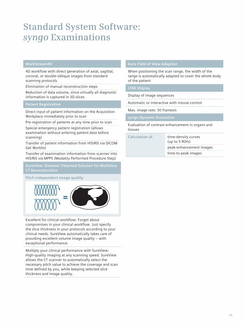
SureView: Siemens’ Patented Solution for Multislice CT Reconstruction
Pitch independent image quality
Excellent for clinical workflow: Forget about compromises in your clinical workflow. Just specify the slice thickness in your protocols according to your clinical needs. SureView automatically takes care of providing excellent volume image quality – with exceptional performance.
Multiply your clinical performance with SureView: High-quality imaging at any scanning speed. SureView allows the CT scanner to automatically select the necessary pitch value to achieve the coverage and scan time defined by you, while keeping selected slice thickness and image quality.
Auto Field of View Adaption
When positioning the scan range, the width of the range is automatically adapted to cover the whole body of the patient
CINE Display
Display of image sequences
Automatic or interactive with mouse control
Max. image rate: 30 frames/s
syngo Dynamic Evaluation
Evaluation of contrast enhancement in organs and tissues
Calculation of time-density curves (up to 5 ROIs)peak-enhancement images time-to-peak images
11
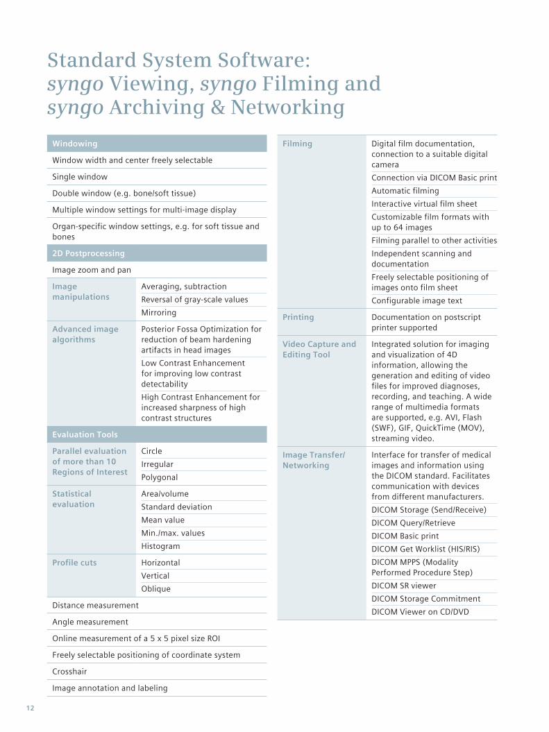
Standard System Software: syngo Viewing, syngo Filming and syngo Archiving & Networking
Windowing
Window width and center freely selectable
Single window
Double window (e.g. bone/soft tissue)
Multiple window settings for multi-image display
Organ-specific window settings, e.g. for soft tissue and bones
2D Postprocessing
Image zoom and pan
Image manipulations
Averaging, subtractionReversal of gray-scale valuesMirroring
Advanced image algorithms
Posterior Fossa Optimization for reduction of beam hardening artifacts in head imagesLow Contrast Enhancement for improving low contrast detectabilityHigh Contrast Enhancement for increased sharpness of high contrast structures
Evaluation Tools
Parallel evaluation of more than 10 Regions of Interest
CircleIrregularPolygonal
Statistical evaluation
Area/volumeStandard deviationMean valueMin./max. valuesHistogram
Profile cuts HorizontalVerticalOblique
Distance measurement
Angle measurement
Online measurement of a 5 x 5 pixel size ROI
Freely selectable positioning of coordinate system
Crosshair
Image annotation and labeling
Filming Digital film documentation, connection to a suitable digital cameraConnection via DICOM Basic printAutomatic filmingInteractive virtual film sheetCustomizable film formats with up to 64 imagesFilming parallel to other activitiesIndependent scanning and documentationFreely selectable positioning of images onto film sheetConfigurable image text
Printing Documentation on postscript printer supported
Video Capture and Editing Tool
Integrated solution for imaging and visualization of 4D information, allowing the generation and editing of video files for improved diagnoses, recording, and teaching. A wide range of multimedia formats are supported, e.g. AVI, Flash (SWF), GIF, QuickTime (MOV), streaming video.
Image Transfer/Networking
Interface for transfer of medical images and information using the DICOM standard. Facilitates communication with devices from different manufacturers.DICOM Storage (Send/Receive)DICOM Query/RetrieveDICOM Basic printDICOM Get Worklist (HIS/RIS)DICOM MPPS (Modality Performed Procedure Step)DICOM SR viewerDICOM Storage CommitmentDICOM Viewer on CD/DVD
12
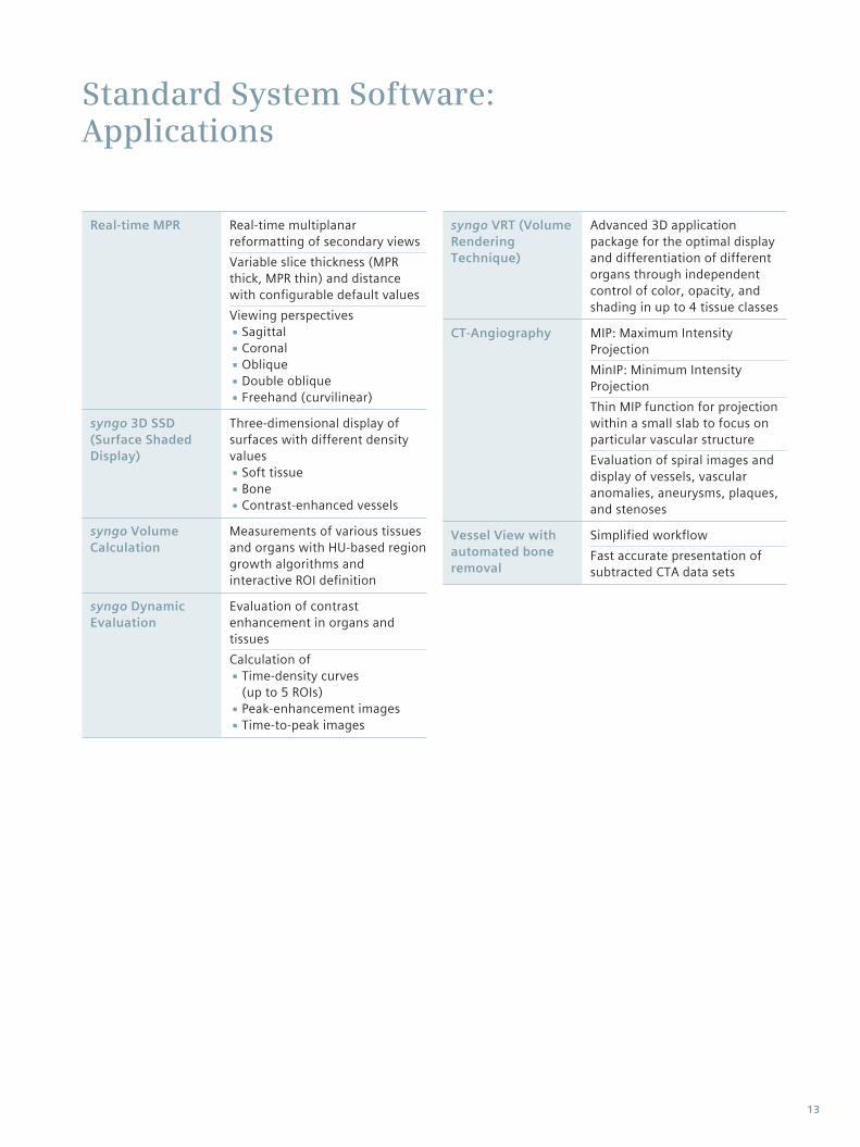
Standard System Software: Applications
Real-time MPR Real-time multiplanar reformatting of secondary viewsVariable slice thickness (MPR thick, MPR thin) and distance with configurable default valuesViewing perspectives
▪Sagittal ▪Coronal ▪Oblique ▪Double oblique ▪Freehand (curvilinear)
syngo 3D SSD (Surface Shaded Display)
Three-dimensional display of surfaces with different density values
▪Soft tissue ▪Bone ▪Contrast-enhanced vessels
syngo Volume Calculation
Measurements of various tissues and organs with HU-based region growth algorithms and interactive ROI definition
syngo Dynamic Evaluation
Evaluation of contrast enhancement in organs and tissuesCalculation of
▪Time-density curves (up to 5 ROIs) ▪Peak-enhancement images ▪Time-to-peak images
syngo VRT (Volume Rendering Technique)
Advanced 3D application package for the optimal display and differentiation of different organs through independent control of color, opacity, and shading in up to 4 tissue classes
CT-Angiography MIP: Maximum Intensity ProjectionMinIP: Minimum Intensity ProjectionThin MIP function for projection within a small slab to focus on particular vascular structureEvaluation of spiral images and display of vessels, vascular anomalies, aneurysms, plaques, and stenoses
Vessel View with automated bone removal
Simplified workflowFast accurate presentation of subtracted CTA data sets
13
FAST Applications
May not be available in all countries Optional
***
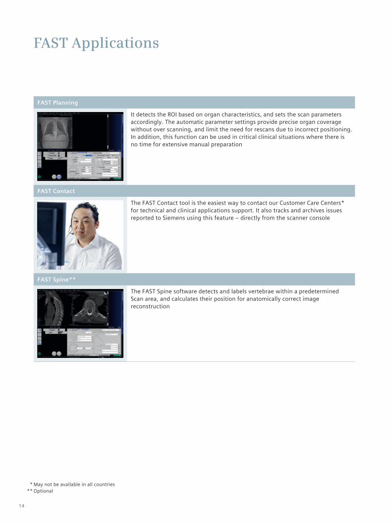
FAST Planning
It detects the ROI based on organ characteristics, and sets the scan parameters accordingly. The automatic parameter settings provide precise organ coverage without over scanning, and limit the need for rescans due to incorrect positioning. In addition, this function can be used in critical clinical situations where there is no time for extensive manual preparation
FAST Contact
The FAST Contact tool is the easiest way to contact our Customer Care Centers* for technical and clinical applications support. It also tracks and archives issues reported to Siemens using this feature – directly from the scanner console
FAST Spine**
The FAST Spine software detects and labels vertebrae within a predetermined Scan area, and calculates their position for anatomically correct imagereconstruction
14
CARE Applications
CARE Filter
Specially designed X-ray exposure filters installed at the tube and the collimator for protocol individual optimization of patient dose and image quality
CARE Bolus CT
Scan mode for contrast bolus triggered data acquisition
Significant improvement of the planning procedure by enabling an optimum spiral scan start after contrast injection
The procedure is based on repetitive low dosemonitoring scans at one slice level and analysis of the time density curve in an ROI (Region of Interest)
CARE Topo
Real-time topogram
Manual interruption possible once desired anatomy has been imaged
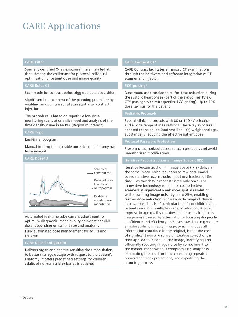
CARE Dose4D
Scan with constant mA
Real-time angular dose modulation
Reduced dose level based on topogram
Automated real-time tube current adjustment for optimum diagnostic image quality at lowest possible dose, depending on patient size and anatomyFully automated dose management for adults and children
CARE Dose Configurator
Delivers organ and habitus-sensitive dose modulation, to better manage dosage with respect to the patient’s anatomy. It offers predefined settings for children, adults of normal build or bariatric patients
CARE Contrast CT*
CARE Contrast facilitates enhanced CT examinations through the hardware and software integration of CT scanner and injector
ECG-pulsing*
Dose modulated cardiac spiral for dose reduction during the systolic heart phase (part of the syngo HeartView CT* package with retrospective ECG-gating). Up to 50% dose savings for the patient
Pediatric Protocols
Special clinical protocols with 80 or 110 kV selection and a wide range of mAs settings. The X-ray exposure is adapted to the child’s (and small adult’s) weight and age, substantially reducing the effective patient dose
Protocol Password Protection
Prevent unauthorized access to scan protocols and avoid unauthorized modifications
Iterative Reconstruction in Image Space (IRIS)
Iterative Reconstruction in Image Space (IRIS) delivers the same image noise reduction as raw-data model based iterative reconstruction, but in a fraction of the time – as raw data is reconstructed only once. The innovative technology is ideal for cost-effective scanners: it significantly enhances spatial resolution while lowering image noise by up to 25%, enabling further dose reductions across a wide range of clinical applications. This is of particular benefit to children and patients requiring multiple scans. In addition, IRIS can improve image quality for obese patients, as it reduces image noise caused by attenuation – boosting diagnostic confidence and efficiency. IRIS uses raw data to generate a high-resolution master image, which includes all information contained in the original, but at the cost of significant noise. A series of iterative corrections is then applied to “clean up” the image, identifying and efficiently reducing image noise by comparing it to the master image without compromising sharpness – eliminating the need for time-consuming repeated forward and back projections, and expediting the scanning process.
Optional*
15
Optional System Software
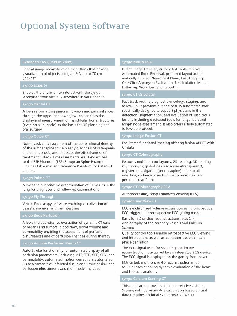
Extended FoV (Field of View)
Special image reconstruction algorithms that provide visualization of objects using an FoV up to 70 cm (27.6’’)*
syngo Expert-i
Enables the physician to interact with the syngo Workplace from virtually anywhere in your hospital
syngo Dental CT
Allows reformatting panoramic views and paraxial slices through the upper and lower jaw, and enables the display and measurement of mandibular bone structures (even on a 1:1 scale) as the basis for OR planning and oral surgery
syngo Osteo CT
Non-invasive measurement of the bone mineral density of the lumbar spine to help early diagnosis of osteopenia and osteoporosis, and to assess the effectiveness of treatment Osteo CT measurements are standardized to the ESP Phantom (ESP: European Spine Phantom. Includes table mat and reference Phantom for Osteo CT studies.
syngo Pulmo CT
Allows the quantitative determination of CT values in the lung for diagnoses and follow-up examinations
syngo Fly Through
Virtual Endoscopy software enabling visualization of vessels, airways, and the intestines
syngo Body Perfusion
Allows the quantitative evaluation of dynamic CT data of organs and tumors: blood flow, blood volume andpermeability enabling the assessment of perfusion disturbances and of perfusion changes during therapy
syngo Volume Perfusion Neuro CT
Auto-Stroke functionality for automated display of all perfusion parameters, including MTT, TTP, CBF, CBV, andpermeability, automated motion correction, automated 3D assessments of infarcted tissue and tissue at risk, andperfusion plus tumor evaluation model included
syngo Neuro DSA
Direct Image Transfer, Automated Table Removal, Automated Bone Removal, preferred layout auto-matically applied, Neuro Best Plane, Fast Toggling, One-Click Aneurysm Evaluation, Recalculation Mode, Follow-up Workflow, and Reporting
syngo CT Oncology
Fast-track routine diagnostic oncology, staging, and follow-up. It provides a range of fully automated tools specifically designed to support physicians in the detection, segmentation, and evaluation of suspicious lesions including dedicated tools for lung, liver, and lymph node assessment. It also offers a fully automated follow-up protocol.
syngo Image Fusion CT
Facilitates functional imaging offering fusion of PET with CT data
syngo CT Colonography
Features multimonitor layouts, 2D reading, 3D reading (fly through), global view (solid/semitransparent), registered navigation (prone/supine), hide small intestine, distance to rectum, panoramic view and perpendicular flight
syngo CT Colonography PEV
Autoprocessing, Polyp Enhanced Viewing (PEV)
syngo HeartView CT
ECG-synchronized volume acquisition using prospective ECG triggered or retrospective ECG-gating modeBasis for 3D cardiac reconstructions, e.g. CT-Angiography of the coronary vessels and Calcium ScoringQuality control tools enable retrospective ECG viewing and interactions as well as computer-assisted heart phase definitionThe ECG signal used for scanning and imagereconstruction is acquired by an integrated ECG device.The ECG signal is displayed on the gantry front coverECG-gated, multi-phase 4D reconstruction in upto 24 phases enabling dynamic evaluation of the heartand thoracic anatomy
syngo Calcium Scoring CT
This application provides total and relative Calcium Scoring with Coronary Age calculation based on trial data (requires optional syngo HeartView CT)
16
Optional Applications for CT Intervention
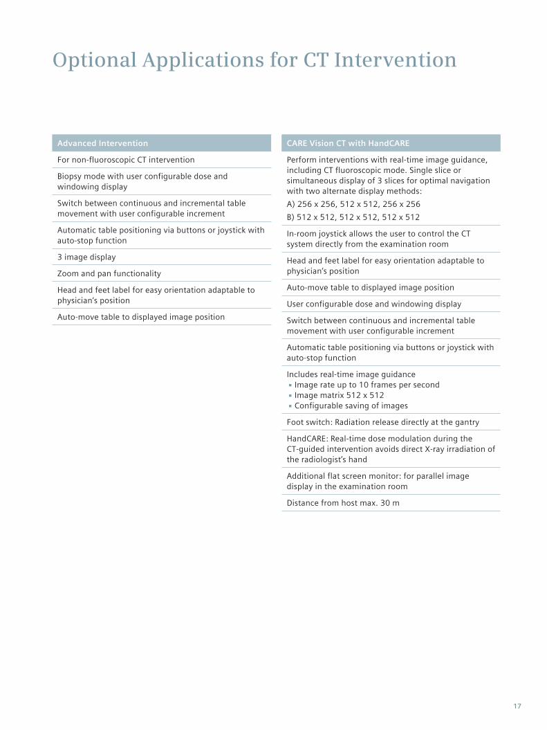
Advanced Intervention
For non-fluoroscopic CT intervention
Biopsy mode with user configurable dose and windowing display
Switch between continuous and incremental table movement with user configurable increment
Automatic table positioning via buttons or joystick with auto-stop function
3 image display
Zoom and pan functionality
Head and feet label for easy orientation adaptable to physician‘s position
Auto-move table to displayed image position
CARE Vision CT with HandCARE
Perform interventions with real-time image guidance, including CT fluoroscopic mode. Single slice or simultaneous display of 3 slices for optimal navigation with two alternate display methods: A) 256 x 256, 512 x 512, 256 x 256 B) 512 x 512, 512 x 512, 512 x 512
In-room joystick allows the user to control the CT system directly from the examination room
Head and feet label for easy orientation adaptable to physician‘s position
Auto-move table to displayed image position
User configurable dose and windowing display
Switch between continuous and incremental table movement with user configurable increment
Automatic table positioning via buttons or joystick with auto-stop function
Includes real-time image guidance ▪ Image rate up to 10 frames per second ▪ Image matrix 512 x 512 ▪Configurable saving of images
Foot switch: Radiation release directly at the gantry
HandCARE: Real-time dose modulation during the CT-guided intervention avoids direct X-ray irradiation of the radiologist’s hand
Additional flat screen monitor: for parallel image display in the examination room
Distance from host max. 30 m
17
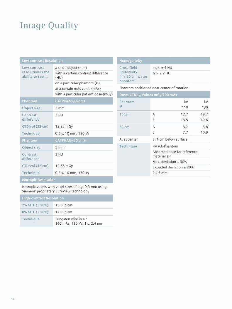
Image Quality
Low-contrast Resolution
Low-contrast resolution is the ability to see …
a small object (mm)with a certain contrast difference (HU)on a particular phantom (Ø)at a certain mAs value (mAs)with a particular patient dose (mGy)
Phantom CATPHAN (16 cm)
Object size 3 mm
Contrast difference
3 HU
CTDIvol (32 cm) 13.82 mGy
Technique 0.6 s, 10 mm, 130 kV
Phantom CATPHAN (20 cm)
Object size 5 mm
Contrast difference
3 HU
CTDIvol (32 cm) 12.88 mGy
Technique 0.6 s, 10 mm, 130 kV
Isotropic Resolution
Isotropic voxels with voxel sizes of e.g. 0.3 mm using Siemens’ proprietary SureView technology
High-contrast Resolution
2% MTF (± 10%) 15.6 lp/cm
0% MTF (± 10%) 17.5 lp/cm
Technique Tungsten wire in air 160 mAs, 130 kV, 1 s, 2.4 mm
Homogeneity
Cross-field uniformityin a 20 cm water phantom
max. ± 4 HUtyp. ± 2 HU
Phantom positioned near center of rotation
Dose, CTDI100 Values mGy/100 mAs
PhantomØ
kV110
kV130
16 cm AB
12.713.5
18.719.6
32 cm AB
3.77.7
5.810.9
A: at center B: 1 cm below surface
Technique PMMA-PhantomAbsorbed dose for reference material airMax. deviation ± 30%Expected deviation ± 20%2 x 5 mm
18
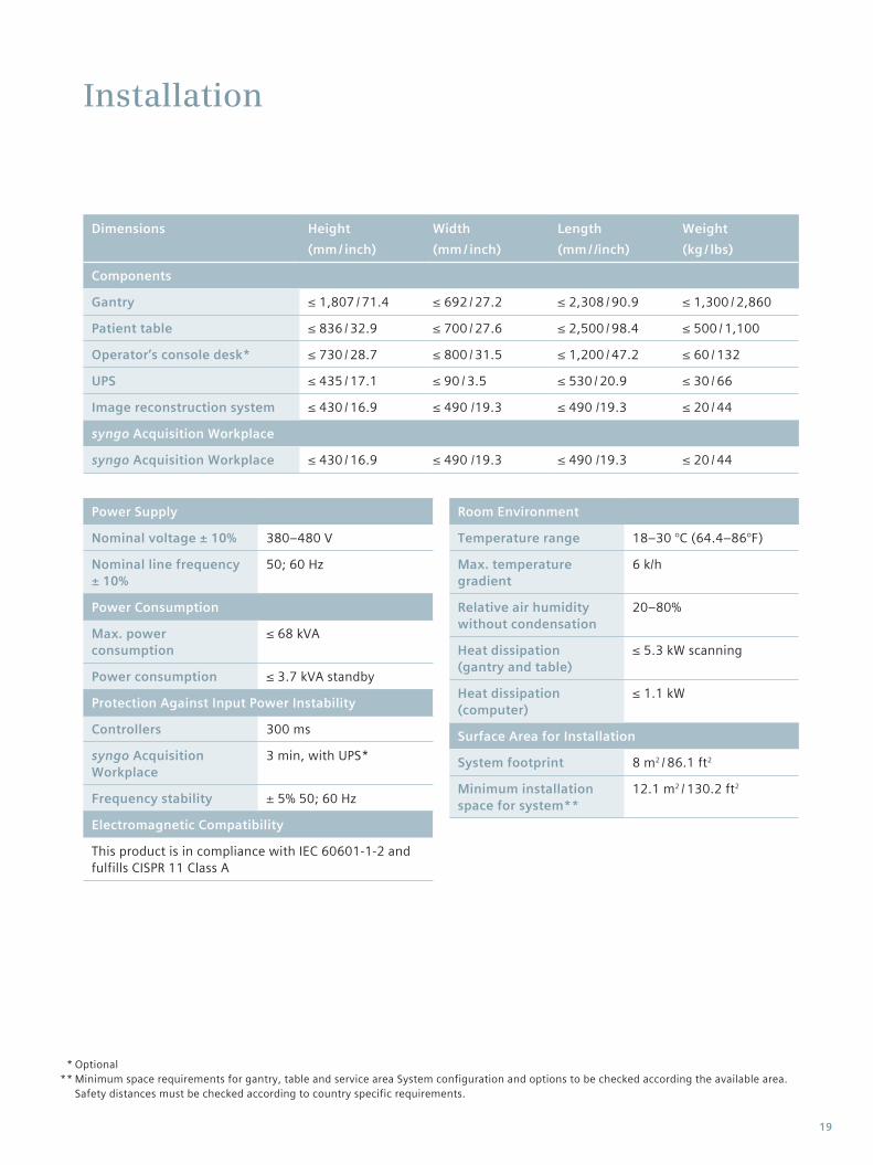
Installation
OptionalMinimum space requirements for gantry, table and service area System configuration and options to be checked according the available area. Safety distances must be checked according to country specific requirements.
* **
Power Supply
Nominal voltage ± 10% 380–480 V
Nominal line frequency ± 10%
50; 60 Hz
Power Consumption
Max. power consumption
≤ 68 kVA
Power consumption ≤ 3.7 kVA standby
Protection Against Input Power Instability
Controllers 300 ms
syngo Acquisition Workplace
3 min, with UPS*
Frequency stability ± 5% 50; 60 Hz
Electromagnetic Compatibility
This product is in compliance with IEC 60601-1-2 and fulfills CISPR 11 Class A
Room Environment
Temperature range 18–30 °C (64.4–86°F)
Max. temperature gradient
6 k/h
Relative air humidity without condensation
20–80%
Heat dissipation (gantry and table)
≤ 5.3 kW scanning
Heat dissipation (computer)
≤ 1.1 kW
Surface Area for Installation
System footprint 8 m2 / 86.1 ft2
Minimum installation space for system**
12.1 m2 / 130.2 ft2
Dimensions Height (mm / inch)
Width (mm / inch)
Length (mm / /inch)
Weight(kg / lbs)
Components
Gantry ≤ 1,807 / 71.4 ≤ 692 / 27.2 ≤ 2,308 / 90.9 ≤ 1,300 / 2,860
Patient table ≤ 836 / 32.9 ≤ 700 / 27.6 ≤ 2,500 / 98.4 ≤ 500 / 1,100
Operator’s console desk* ≤ 730 / 28.7 ≤ 800 / 31.5 ≤ 1,200 / 47.2 ≤ 60 / 132
UPS ≤ 435 / 17.1 ≤ 90 / 3.5 ≤ 530 / 20.9 ≤ 30 / 66
Image reconstruction system ≤ 430 / 16.9 ≤ 490 /19.3 ≤ 490 /19.3 ≤ 20 / 44
syngo Acquisition Workplace
syngo Acquisition Workplace ≤ 430 / 16.9 ≤ 490 /19.3 ≤ 490 /19.3 ≤ 20 / 44
19
www.siemens.com/healthcare
Global Siemens HeadquartersSiemens AG Wittelsbacherplatz 2 80333 Muenchen Germany
On account of certain regional limitations of sales rights and service availability, we cannot guarantee that all products included in this brochure are available through the Siemens sales organization worldwide. Availability and packaging may vary by country and is subject to change without prior notice. Some/All of the features and products described herein may not be available in the United States.
The information in this document contains general technical descriptions of specifications and options as well as standard and optional features which do not always have to be present in individual cases.
Siemens reserves the right to modify the design, packaging, specifications and options described herein without prior notice. Please contact your local Siemens sales representative for the most current information.
Global Business UnitSiemens AGMedical SolutionsComputed Tomography & Radiation OncologySiemensstr. 1DE-91301 ForchheimGermanyPhone: +49 9191 18-0 Fax: +49 9191 18 9998www.siemens.com/ct
International Version. Not for distribution in the U.S.
Global Siemens Healthcare HeadquartersSiemens AG Healthcare Sector Henkestraße 127 91052 Erlangen Germany Phone: +49 9131 84-0 www.siemens.com/healthcare
Note: Any technical data contained in this document may vary within defined tolerances. Original images always lose a certain amount of detail when reproduced.
The statements contained herein are based on the actual experience of Siemens customers. Siemens maintains data on file to support these claims. However, these statements do not suggest or constitute a warranty that all product experience will yield similar results. Results may vary, based on the particular circumstances of individual sites and users.
Please find fitting accessories: www.siemens.com/medical-accessories
Order No. A91CT-00240-05T1-7600 | Printed in Germany | CC CR 2106 04141. | © 04.2014, Siemens AG