Embed Size (px)
Citation preview
SOMA: A method fordeveloping service-orientedsolutions
&
A. Arsanjani
S. Ghosh
A. Allam
T. Abdollah
S. Ganapathy
K. Holley
Service-oriented modeling and architecture (SOMA) has been used to conduct
projects of varying scope in multiple industries worldwide for the past five years. We
report on the usage and structure of the method used to effectively analyze, design,
implement, and deploy service-oriented architecture (SOA) projects as part of a fractal
model of software development. We also assert that the construct of a service and
service modeling, although introduced by SOA, is a software engineering best practice
for which an SOA method aids both SOA usage and adoption. In this paper we present
the latest updates to this method and share some of the lessons learned. The SOMA
method incorporates the key aspects of overall SOA solution design and delivery and is
integrated with existing software development methods through a set of placeholders
for key activity areas, forming what we call solution templates. We also present a fractal
model of software development that can enable the SOMA method to evolve in an
approach that goes beyond the iterative and incremental and instead leverages
method components and patterns in a recursive, self-similar manner opportunistically
at points of variability in the life cycle.
INTRODUCTIONThe evolution of software engineering has passed
through various eras, including structured pro-
gramming, analysis, and design and undulated
between data orientation or process orientation until
it finally brought us to the notion of object
orientation,1,2
where data and process unite to form
the object (class). An object exposes a set of
methods that can be invoked to manipulate under-
lying data structures whose implementations are
hidden from the invoker. Object-oriented (OO)
analysis and design (OOAD) methods abounded2
in
the early 1990s. Component-based software engi-
neering then advanced the state of the art and built
on the foundation laid by object orientation. The
focus on the unit of deployment as the component
gradually gave way to a protocol of remote
invocation of those components over a distributed
network using hitherto unprecedented consensus
�Copyright 2008 by International Business Machines Corporation. Copying inprinted form for private use is permitted without payment of royalty providedthat (1) each reproduction is done without alteration and (2) the Journalreference and IBM copyright notice are included on the first page. The titleand abstract, but no other portions, of this paper may be copied or distributedroyalty free without further permission by computer-based and otherinformation-service systems. Permission to republish any other portion of thepaper must be obtained from the Editor. 0018-8670/08/$5.00 � 2008 IBM
IBM SYSTEMS JOURNAL, VOL 47, NO 3, 2008 ARSANJANI ET AL. 377
around standards in this arena. Distributed objects
and remote-object invocation using Object Manage-
ment Group CORBA**, Open Software Foundation
Distributed Computing Environment (DCE), Micro-
soft Component Object Model (COM), and Sun
Java** Remote Method Invocation (RMI) have
continued to mature.
Eventually, within client/server and network-centric
computing environments in which the client knows
about the identity of the server, a higher degree of
separation of concerns emerged in terms of n-tier
Web-based computing (i.e., e-business). This ad-
vanced with the emergence of standards within Web
services under which provider and consumer were
separated by a contract (the interface) and by the
choice of binding (a concrete protocol and data
format specification) that provided flexibility for the
underlying technology protocols to be used. Capa-
bilities that were significant to business and could
be invoked over a network using these standards
heralded the emergence of a service-oriented archi-
tecture (SOA).
Many definitions have been proposed for services.
We have found the ones below to be practical and
useful on actual projects.
From a business perspective, a service is a well-
defined, encapsulated, reusable, business-aligned
capability. A service operation is the elementary part
of a service and specifies the associated inputs,
purpose (function, duty or obligations), and outputs
(artifacts, products, outcomes, or deliverables). A
service is fully defined by a service description, a
published document or artifact that outlines the
overall objective of the service and its inputs,
purpose, outputs, scope, responsibility, governance,
sustainability (provision period, maintenance, and
repair), and qualities of service provisioning.
From an information technology (IT) perspective, a
service is a discoverable, invokable software re-
source that has a service description and interface
and is configurable using policies. The service
description is available for searching, binding, and
invocation by a service consumer. The service
description implementation is realized through a
service provider that delivers quality of service
(QoS) requirements for the service consumer.
With the advent of SOA, the programming principle
that was learned from OO—program to interfaces
rather than implementations3—was elevated to the
level of software architecture in which an actual
logical layer is used to describe services.4,5
It is often
the case that programming concepts evolve into
architectural constructs and then into methods.
Initial efforts to use traditional OOAD methods to
support Web services and SOA found those methods
insufficient to support the challenges and nuances
required by new first-class constructs of service
orientation, namely services, the components im-
plementing those services, the flows of business
processes choreographing those services,6
and the
information requirements and policies associated
with services. To elaborate, services would be
designated as the logical interface mechanism for
decoupling a service consumer from a service
provider through a standards-based protocol that
allows invocation of distributed software resources
on an as-needed basis. Further description of how
services interact with their underlying realizations
and implementations symbolized in the components
of the application architecture and how they would
be combined and composed in a new notion, termed
choreography or orchestration into business process
flows, required a new set of method constructs. This
does not imply that the only way to leverage
services is through composition and choreography.
Services can also be leveraged by using them at a
variety of levels: for example, services used to
expose legacy functionality, simple services to
provide new functionality, services used to increase
reuse and refactoring in order to reduce the cost of
system maintenance, services used to expose
business-significant capabilities, and composite ser-
vices.7
Paradigm shift from OO to SOA
The lure of reusability has enticed many companies
to evaluate and adopt SOA as an enabler for wider
transformation initiatives or as an enabler for a
development or systems-integration project. Our
experiences working with hundreds of projects and
executives (business and IT) surface a more refined
objective. In the case of business stakeholders, a
recurrent objective is to have greater flexibility in
response to changing market demands. They there-
fore advocate using SOA tenets to make it possible
to locate and assemble the component parts of new
products and applications rather than having to buy
new, hard-coded solutions or spend precious time
and money with integration.
ARSANJANI ET AL. IBM SYSTEMS JOURNAL, VOL 47, NO 3, 2008378
IT stakeholders, on the other hand, are being asked
by the business to do more for less. Their view is
that if SOA works, it can confer lower development
costs through the ability to reuse common bits of
functionality in multiple applications. This can
result in a greater ease of doing business, more
flexibility, and the enabling of more-direct and
more-customized interaction with partners, suppli-
ers, and consumers.
The change from OOAD to SOA can be seen on a
spectrum: from those who advocate that ‘‘only the
packaging is new’’ to those who believe there is a
significant paradigm shift. We will elaborate the
latter view.
Use-cases are often used to capture functional
requirements of OO systems. A use-case captures a
set of static object interactions that ultimately realize
the use-case. These flows are most often hard-
coded. This does not allow the easy recombination
of functionality. In contrast, a service-case will
identify the reconfigurable choreography of a set of
service operations, each a unit of functionality. This
flow is not hard-coded; instead of endeavoring to
initially identify the objects that will sequence the
interactions, the focus is on the set of business-
aligned IT services that collectively enable the
fulfillment of business goals, and the services can be
recombined in unanticipated service contexts.
Rather than being simply a user interacting with a
system, it can be seen as an ecosystem of providers
and consumers with often interchangeable roles that
leverage the services through policies and new
combinations in ever-changing service-cases.
The notion of a service as previously described
provides an opportunity to increase the flexibility
and reuse of business functionality within an
enterprise and with partners. Our project experi-
ences demonstrate that guidance is required for how
services, components, and flows are identified and
specified in much the same way as was done for
objects in object orientation. Hence, we developed a
service-oriented method in IBM called service-
oriented modeling and architecture (SOMA).8
SOMA is an end-to-end software development
method for building SOA-based solutions. This SOA
method was harvested from hundreds of successful
experiences and lessons learned from the difficulties
and challenges encountered in early SOA design and
implementation projects. The expanse of these
projects was wide and deep, ranging from diverse
fields such as health care, telecommunications, and
financial services to public-sector implementation
projects. The key objective of harvesting these
experiences was to arrive at a method that consisted
of a set of task-performance roles used to produce
deliverables (work products) using guidance and
best practices from the emerging field of service
orientation. IBM invested in this effort to develop
methods to support the latest software engineering
best practices associated with SOA. Over the past
five years, SOMA has inspired such SOA terminol-
ogy and concepts as service-oriented modeling,
service identification, multiple complementary ser-
vice identification techniques (including harvesting
services from business processes), business use
cases, usage of business-driven imperatives to
identify services, and separation of the identifica-
tion, specification, and design and realization of
services.
SOMA is a software development life-cycle method
invented and initially developed in IBM for design-
ing and building SOA-based solutions. This method
defines key techniques and provides prescriptive
tasks and detailed normative guidance for analysis,
design, implementation, testing, and deployment of
services, components, flows, information, and
policies needed to successfully design and build a
robust and reusable SOA solution in an enterprise.
The latest release of the method (v.3.1) has major
additions and enhancements from the previous
release8
(v.2.x), based on feedback from clients,
practitioners, and the industry at large.
In this paper, we provide a description of the
method illustrated by two case studies: one concise
and one more elaborate. We introduce the core
concepts and key activities of SOMA and use a case
study drawn from real-life client experiences to
illustrate its key activities. Subsequently, we explore
the latest enhancements and features that have been
inspired by real-world project experiences calling for
these features.
Our first case study is concise and demonstrates the
value derived from using the capabilities defined
within SOMA that focus on the solution of key
business problems. We use a pattern format to
convey this case study. The next case study is more
IBM SYSTEMS JOURNAL, VOL 47, NO 3, 2008 ARSANJANI ET AL. 379
elaborate and demonstrates the major phases,
activities, and sample outputs.
Telecommunications: A short case study
Context: The case study is based on a telecommu-
nications company that we will fictitiously name
Good Telecom. The company decided to focus on a
service-order creation process to create new services
for an SOA project. They wanted to ensure that the
service plans and service features would be offered
consistently across the various channels: point of
sale, Web, and customer service representatives.
The business logic and rules were maintained in
their mainframe computer. The channels were
allowed to override the price plans offered by the
back-end systems. This often led to a situation in
which a user could get certain features or price plans
at a better discount from one channel compared
with the other. The company quickly realized that
this is not a good business practice and made it
business goal to provide consistent services across
all channels.
Problem: To address the business goal of providing
consistent service across channels while creating
new service orders. Discussions with the client
subject-matter experts and detailed analysis of the
relevant systems and IT environment revealed the
following challenges and opportunities:
� Duplicate logic had a negative impact on mainte-
nance and support costs.� Multiple calls to back-end systems resulted in
expensive mainframe CPU-cycle consumption and
had a negative impact on network traffic.� An inflexible design and architecture could not
support variations—for example, varying features
by region.� Performance was degraded by unstructured code,
duplicate code, and code that was not required—
that is, it did not support any specific business
function.
Solution: To address these problems, the following
SOMA capability patterns, also known as techniques
(reusable parts of a larger method) were applied:
� Service identification: Decompose the service-
order creation process to identify services.� Service specification: Develop service-interface and
message specifications, service dependencies,
service interactions, the component model, and
identify reusable patterns.� Existing asset analysis: Conduct detailed analysis
of COBOL (Common Business Oriented Language)
modules and copybooks. This was needed to
develop an approach to either consolidate or
refactor the code.� Service refactoring and rationalization: Determine
service granularity and apply a defined set of
criteria called a service litmus test (SLT) to
determine which candidate services are appropri-
ate to expose—that is, to publish using Web
Services Description Language (WSDL).� Technical feasibility exploration: Identify potential
viable solutions to various problems, such as the
conversational nature of the service request when
the front-end systems have to interact with back-
end systems several times in order to service the
request. Multiple fine-grained transactions to
fulfill a service request have an impact on the
service performance and hence user experience.
Consequences: The application of the above capa-
bility patterns helped in developing a solution to
resolve the challenges:
� Duplicate logic was addressed by analyzing
existing assets to develop refactoring approaches
and by creating common reusable components.� The problem of multiple calls to back-end systems
was addressed by refactoring logic into appropri-
ate SOA layers, by adding mediation logic in the
integration layer and business logic in the service-
component layer, and by caching.� The inflexible design and architecture was recti-
fied by refactoring the code and by creating
common reusable components.� Performance was improved by all of the above.
Case study: XYZ Financial ServicesThe XYZ Financial Services case study is a com-
posite of real-world experiences with multiline
financial institutions. We use it to describe SOMA
concepts and the key activities of the method that
are recommended to identify, specify, realize,
implement, and deploy services as prescribed by the
SOMA method.
XYZ Financial Services, Inc., (XFS) has two major
lines of business: insurance and investment. Its
market analysis had revealed that the aging of baby
boomers and their changing needs in their retire-
ARSANJANI ET AL. IBM SYSTEMS JOURNAL, VOL 47, NO 3, 2008380

ment years presented unprecedented opportunities
and challenges for financial institutions such as
theirs.
The analysis by XFS had revealed that as the baby
boomers advanced toward retirement age, their
investment strategies were becoming more conser-
vative and risk-averse, such as shifting a portion of
their retirement savings from stocks and securities
to savings accounts and certificates of deposits
(CDs) in more-traditional, regulated markets that are
insured by the Federal Deposit Insurance Corpora-
tion in the United States. The demise of defined
pension plans and the trend toward defined contri-
bution plans by most employers in the U.S. were
further amplifying this trend. XFS also realized that
no-interest or low-interest-bearing checking and
saving accounts were increasingly becoming an
important source of revenue, and CDs were pro-
viding a long-term source of funds.
XFS wanted to capitalize on these trends by
designing market products and services that would
attract and retain these customers. Thus, XFS set a
goal of diversifying its business by providing
banking services and relatively low-risk products
such as saving accounts, CDs, money market
accounts, and value-added online banking services
(e.g., online bill payment, fund transfer, ability to
view detailed account transactions and activity, e-
statements, and check ordering). They selected the
SOMA method as the means to accomplish this goal.
OVERVIEW OF THE SOMA METHOD
As a software development life-cycle method for
developing SOA-based solutions, or any solution
using service-oriented principles, SOMA defines key
techniques and describes the roles on a SOA project
and a work breakdown structure (WBS). The WBS
includes tasks, the input and output work products
for tasks, and the prescriptive guidance needed for
detailed analysis, design, implementation, and
deployment of services, components, and flows
needed to build a robust and reusable SOA
environment. The SOMA method includes the seven
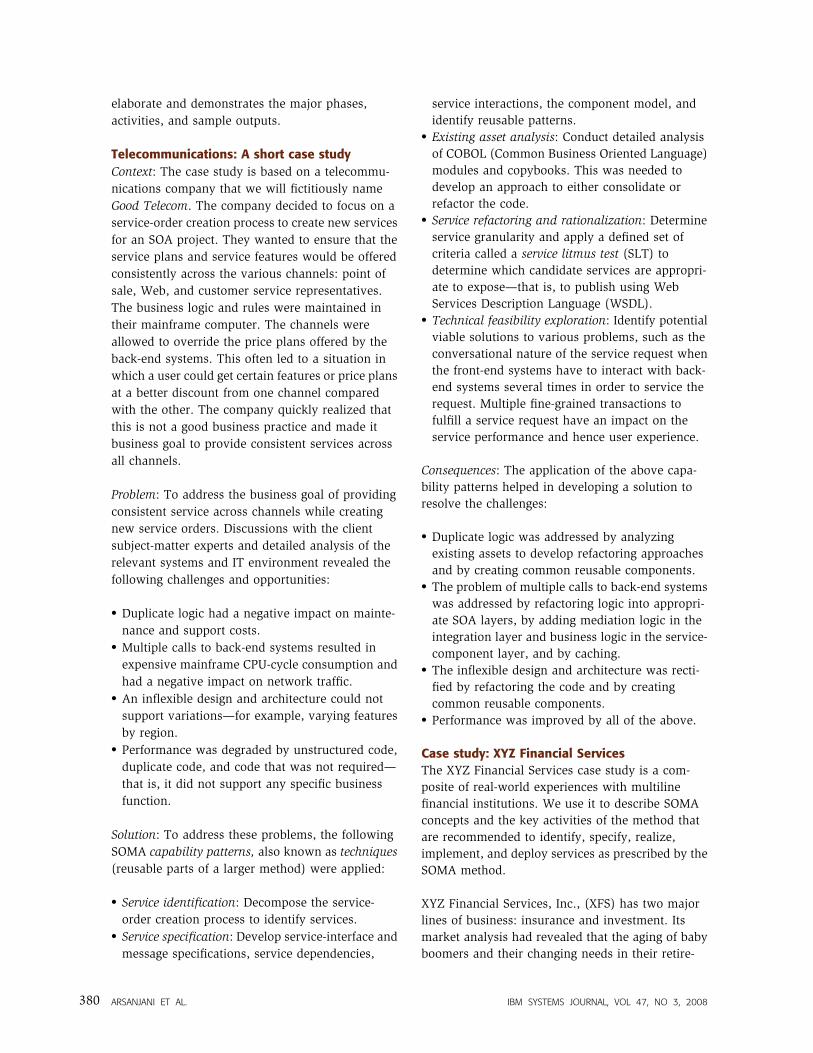
major phases shown in Figure 1. The fractal phases
contain capabilities that can be leveraged as needed
in different sequences. (Fractal is used semi-meta-
phorically: We apply method capabilities in a self-
similar manner within varying scopes. SOMA has a
fractal software development life cycle because
SOMA applies method components—capability pat-
terns—in a self-similar manner recursively in small
release or iteration cycles, focusing on addressing
technical risk and delivering software valued by the
business.) Realization, for example is leveraged in
all phases. No rigid sequencing is implied. In a
fractal model, phases will consist of capabilities that
may be used by other phases. Governance serves as
the context and background for the service-oriented
life cycle. SOMA provides support for and linkages
to the two main aspects of governance: design-time
and runtime governance.9
Fractal model for service-oriented software
development
It is important to note that SOMA phases are not
linear. They are applied in a risk-driven, iterative,
and incremental approach using a nuance peculiar
to the SOA life cycle. The life cycle of an SOA project
uses a fractal approach that is a combination of two
key principles. The first principle of fractal software
development is the application of method tasks to
self-similar scope: that is, tasks are done in a similar
way in larger or smaller boundary scopes (whether
enterprise-wide, line-of-business, or single project
initiatives). The notion of similarity indicates that
the application of principles is similar but not
identical, meaning that as we approach larger
scopes, even though the same tasks apply, the
additional work needed has to evolve in order to
take into account factors that arise from the larger
scope. Thus, the SOA method can be applied to SOA
solution development at the level of projects, lines
of business, between business lines, enterprise-
wide, and between business partners.
The SOMA method is also fractal in nature, even in a
given scope. SOMA is composed of capability
patterns representing techniques applied in the
method. Many of these capability patterns are
executed in all phases in SOMA with different
degrees of elaboration and precision. For one
example, we make exposure decisions based on the
information we know about the services during
identification and then we elaborate and refine the
exposure decisions in the specification phase when
we know more about the nonfunctional require-
ments of the services. A second example is that we
analyze the existing assets in the identification
phase to identify systems and system functions that
can be leveraged to realize the services, but we
expand further on that analysis in the specification
IBM SYSTEMS JOURNAL, VOL 47, NO 3, 2008 ARSANJANI ET AL. 381
phase to identify existing components and objects
and their operations that we can reuse to realize the
services. And as a third example, we initially model
dependencies among services when we define the
service portfolio but we further elaborate the
dependencies of services with components and
physical systems when we identify components and
make decisions to realize the services. In addition,
we apply similar principles in successive levels of
detail to elaborate the SOA reference architecture as
we progress in the SOMA life cycle.
The second principle of fractal software develop-
ment is successive iteration. The concepts of
iterative and incremental development life cycles
have existed for a long time. They focus on
prioritization and mitigation of risk factors in order
to ensure the product quality of the solution. This
has its roots in the spiral model of software
development by Boehm.10
Successive iteration is
connected with the notion of service evolution and
implies a focus on not only the risks associated with
the implementation, but also with the dependencies
associated with the service portfolio as services
evolve through the life cycle. The notion of service
dependencies on other services, and potentially
other dependencies on actual back-end systems,
databases, and components, must be called out.
Thus, in SOMA, a prioritization of the service model
is conducted and based on a service-dependency
diagram and takes into account the risk factors
involved in the IT aspects of the architecture. A
subset of services is prioritized for the next
implementation release in which technical feasibil-
ity is planned for, measured, and exercised within a
proof-of-concept prototype.
Over time, functionality or business capabilities that
were not selected for service exposure may get
Figure 1SOMA phases—a fractal model of software development
Deployment,monitoring, andmanagementPackaging and provisioning,process and performancemonitoring, andmanagement
Implementationbuild/assembly:Construction, generation, assembly, integration Testing: Unit, integration, UAT
Runtime governance,monitoring and management
Design-time governance
SolutionmanagementHybrid solution type selection, method adoption and integration, project management,enterprisearchitecture
RealizationDecisions,solution templates and patterns, detailed SOA referencearchitecture,technical feasibilityprototyping
Business modeling andtransformation Business architecture and models, SOA maturity, andtransformation roadmaps
Specificationof services,components, flows and information
IdentificationIdentifying services,components, flowsand information
ARSANJANI ET AL. IBM SYSTEMS JOURNAL, VOL 47, NO 3, 2008382
identified in a later iteration, when they are
reassessed using the SOMA SLTs, and a determina-
tion is made whether they should be exposed as
services in this release or implemented in a
traditional manner.
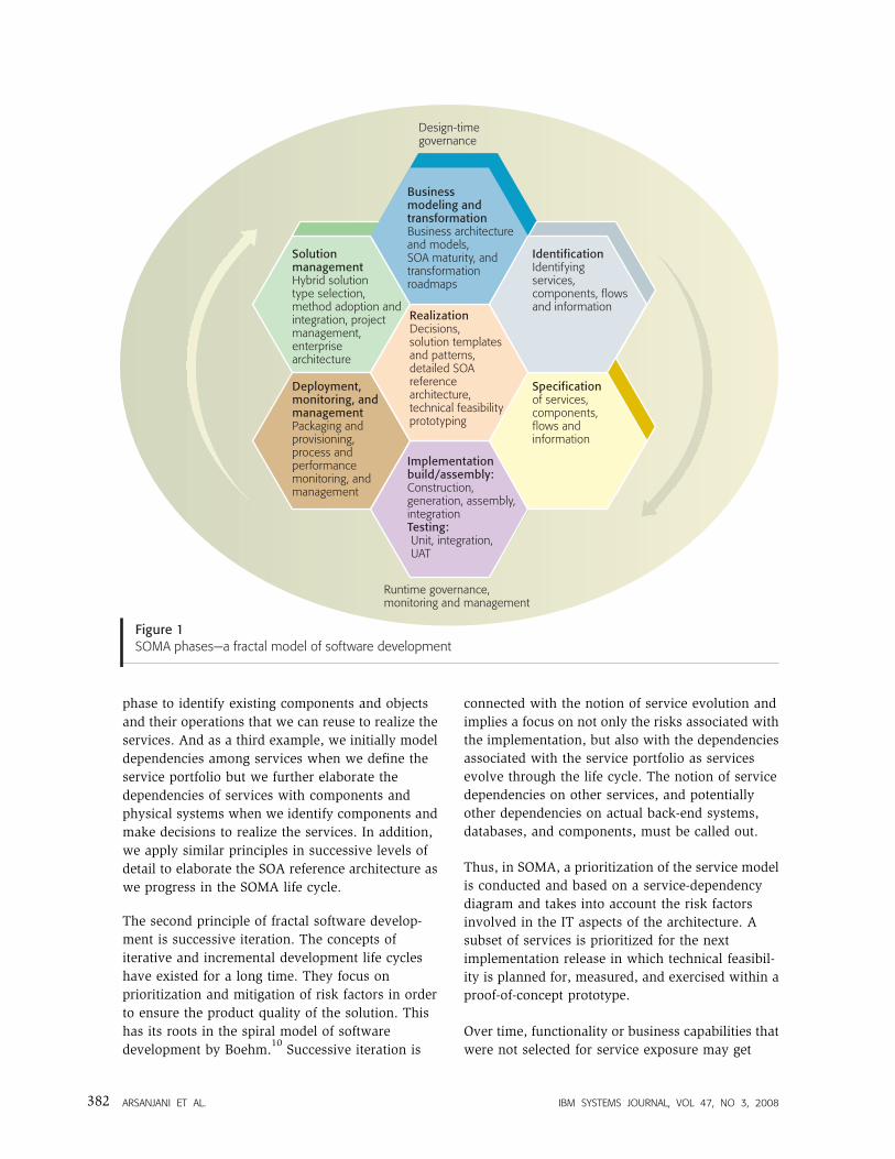
The flow shown in Figure 2 is a sequential depiction
of the overall fractal flow at a high level. Whereas
Figure 1 depicts the capability patterns and fractal
nature of the SOMA method, Figure 2 illustrates a
typical process flow of an engagement executing the
SOMA method. In this paper we focus primarily on
the identification, specification, and realization
phases. In the following sections, for lack of space,
we do not discuss the details of the roles; we do
discuss activities, tasks, some work products, and
some guidance concerning tasks. Collectively this
constitutes the method.
Business modeling and transformation
In this phase, the business is modeled, simulated,
and optimized, and a focal area for transformation is
identified that will drive a series of subsequent
projects using the set of phases shown in Figure 2
and discussed in the following sections. Note that
this phase is not strictly required but is highly
recommended.
Solution management
SOA solutions are hybrid in nature and typically
include multiple solution types. This is because
services identified and specified during the early
phases in SOMA can be realized in subsequent
phases of SOMA by different scenarios, such as
custom development, legacy integration and trans-
formation, and package application integration.
SOMA is designed to support the hybrid nature of
SOA solutions and it prescribes specific activities
and guidance to implement each of the above
solution types. In the SOMA method, the method
content common to all SOA solution types is
separated from the variable method content that is
dependent on specific solution types. The variable
method content—tasks, work products, roles, and
guidance—specific to each of the solution types is
defined and externalized as a method template
called a solution template. At the beginning of an
engagement and subsequently when realization
decisions for the services are made, we typically
discover and select the solution types needed to
Conduct goal-servicemodeling
Figure 2SOMA life-cycle high-level flow
Business modeling and transformation 0 Define
businessarchitecture and business models
Solutionmanagement
Initiate projectmanagement activities
Conduct methodadoption workshop
Select solutiontemplates and patterns
• Customize delivery method
Identification
4
Business domainsand processes in
scope
6
Service model
Service model
• Functional area• Process• Information• Rules• Variations
7
• SLT
5
Refactor and rationalize services
1
2
3
Deployment,Monitoring, andManagement19
20
21 Monitor and manageprocesses and performance
Deploy services
Execute user-acceptance test
Implementation
16
17
18
Construct, generate andassemble services
Execute unit test
Execute integrationand system test
Realization
12
13
14
15
Refine and detailcomponents
Establish realizationdecisions
Perform technicalfeasibility exploration
Detail SOA solutionstack layers
Specification
Specify services
Analyze subsystems
Specify components
Refactor and rationalize services
• Composition• Flows• Operations• Messages• NFRs
8
9
10
11
Decomposedomains
Analyze existingassets
IBM SYSTEMS JOURNAL, VOL 47, NO 3, 2008 ARSANJANI ET AL. 383
build an SOA solution for a client. The activities and
tasks from the selected solution templates are
inserted into predefined extension points in the
SOMA method to provide a comprehensive process
to execute for the engagement.
In the case of XFS, the existing customer relation-
ship management (CRM) system is used to access
customer information from the customer database.
Hence, the solution template for package application
integration was selected. This solution template
provides prescriptive tasks necessary to integrate
with packaged applications such as, in this case, a
CRM system from SAP AG.
Identification phase
The identification phase pertains to the identifica-
tion of the three fundamental constructs of SOA:
services, components, and flows. Our experience
indicates that it is a best practice to utilize a set of
complementary service identification techniques.
Relying on a single technique tends to create an
incomplete set of services. This introduces infor-
mation entropy early in the development life cycle,
often to be remedied at greater cost later in the
service life cycle as it entails greater efforts of
service refactoring. Additionally, this often leads to
the failure to identify service dependencies early on,
which impacts release planning and, ultimately,
project delivery.
We conduct an initial pass of service identification
techniques to identify the candidate services. Upon
further assessment, we perform service refactoring
and rationalization opportunistically, which in-
cludes the essential task of filtering out those
business capabilities that will be exposed as services
within the scope of the project. The latter assess-
ment includes the SLT technique.
The recommendation is to start by aligning services
with business goals, a step we call goal-service
modeling (GSM). This aligns IT execution with
business drivers, imperatives, and objectives as well
as monitoring and managing the scope of further
business-process modeling and existing asset anal-
ysis.
SOMA identification is a process of identifying
candidate services and creating a service portfolio of
business-aligned IT services that collectively support
the business processes and goals of the organiza-
tion. It is done through the process of assessing
existing functionality to see if it can be placed in the
service model, and by determining missing IT
capabilities that will be needed to support the
alignment of business strategy, goals, and processes.
Thus, multiple complimentary techniques are in-
troduced during SOMA identification to identify
candidate services as well as components and flows.
In this paper, we primarily focus on service
identification rather than component and business-
process flow identification, although the latter is
also mentioned.
Services are initially designated as candidate during
identification because all identified business capa-
bilities and functionalities will not have to be
exposed as services nor will funding be available to
cover them all. Furthermore, only the relevant
subset of candidate services will become exposed
services, and thus participate in a given release. The
entire service portfolio will often have to be
staggered over several releases. Thus, services
designated as exposed will still be implemented,
albeit not as Web services but as functionality
implemented in the ordinary course of software
development, such as methods on the component or
mapped to application program interfaces (APIs) or
transactions of the back-end legacy system. When
and if business prioritization of needs is able to
make a strong case, some of those unexposed
services will be reevaluated using the service
refactoring and rationalization activity and may
make their way back into the service portfolio over
the lifetime of another release.
Three main service identification techniques
Service identification follows three main comple-
mentary techniques: GSM, domain decomposition,
and existing asset analysis. GSM uses an approach
that is predicated on business challenges and
opportunities, corporate strategy, and business
goals. Domain decomposition—which comprises
multiple service identification techniques of its
own—uses a top-down analysis technique that is
focused on business process modeling, rules,
information, and variation-oriented analysis. Asset
analysis addresses the fact that an organization
typically will have acquired more than a quarter of a
century of legacy systems and applications that are
integrated and enhanced and whose ongoing sup-
port requires a significant amount of funding. One of
ARSANJANI ET AL. IBM SYSTEMS JOURNAL, VOL 47, NO 3, 2008384
the main value drivers of SOA is to leverage existing
resources and redirect them in new ways to support
business needs. This bottom-up approach takes a
look at the existing application portfolio and other
assets and standards that may be used in identifying
good candidates for service exposure.
GSM combines the top-down and bottom-up ap-
proaches and pulls them together into alignment.
Over the course of the project and over the course of
several projects, which may be guided by enterprise
architecture, all services should be traceable back to
a business goal that originates in the goal-service
model.
Component and service flow identification tech-
niques
Domain decomposition includes an activity called
functional area analysis that provides a structural
partitioning of the business domains into distinct
business functional areas. This provides a natural
means of identifying components later in the life
cycle. Process decomposition and process modeling,
also parts of domain decomposition, provide the
opportunity to not only identify services but the
service flows that will be used to orchestrate them.
Variation-oriented analysis and design (VOAD)
provides a means to capture variations in business
processes, both structural variations (such as
information and component variations) and varia-
tions in business rules and policies. Thus, VOAD
identifies commonality and externalizes variations11
that will play a significant role in reducing the
impact of potential future changes to service
portfolio components and processes.
Therefore, SOMA identification provides us with the
techniques (activities, roles, work products, and
guidance) to derive appropriate service abstractions
at the right level of granularity from business
requirements, business processes, existing systems
and applications, business goals, and anticipated
potential variation types. It accomplishes this by
making use of complementary identification tech-
niques in combination.
GSM maintains the alignment of services with
business goals and refines the subsequent scope of
business processes being evaluated as well as
existing systems and assets. It accomplishes this
alignment by ensuring that the scope of transfor-
mation is appropriately constrained to only those
processes and existing resources that are absolutely
essential to the solution of the problem, thus saving
time and energy within the overall life cycle.
Goal-service modeling
In GSM, a generalized statement of business goals
relevant to the scope of the project is decomposed
into subgoals that must be met in order for the
higher-level goals to be met. This hierarchical
decomposition then leads to a set of actionable goals
which lead to identifying the services that will help
in fulfilling the subgoals. It is also important to
identify key performance indicators (KPIs) to
provide an objective basis for evaluating the degree
to which the goal has been achieved. KPIs and
metrics identified during this process are used to
measure, monitor, and quantify the success of the
SOA solution in fulfilling business needs subsequent
to the building and deployment of services in the
service model.
In the XFS case study, the highest-level goal,
determined by the client, was to attract and retain
customers from the baby-boomer generation in the
investment and insurance lines of business by
offering them banking services that are enabled
through multiple channels such as online, self-
service portals, and interactive voice response
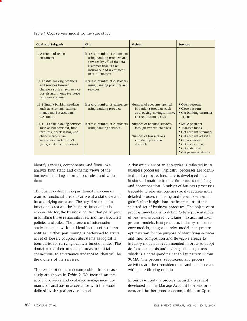
systems (see Table 1).
GSM helped define the scope of the client engage-
ment and to identify parts of the business that
needed transformation and change to achieve the
high-level goals. By using business goals, it played a
very important role in identifying which business
processes should be focused on, resulting in the
identification of those services that would have the
greatest business impact. This also provides trace-
ability between business goals and services. The
number of candidate services identified during
process decomposition can be quite high. However,
through GSM and business-process decomposition,
the set of candidate services that meets business
goals greatly refines the scope of the service
orientation. The service portfolio from GSM consists
of those listed in the Services column of Table 1.
Domain decomposition
This technique focuses on top-down analysis of
business domains and business process modeling to
IBM SYSTEMS JOURNAL, VOL 47, NO 3, 2008 ARSANJANI ET AL. 385
identify services, components, and flows. We
analyze both static and dynamic views of the
business including information, rules, and varia-
tions.
The business domain is partitioned into coarse-
grained functional areas to arrive at a static view of
its underlying structure. The key elements of a
functional area are the business functions it is
responsible for, the business entities that participate
in fulfilling those responsibilities, and the associated
policies and rules. The process of information
analysis begins with the identification of business
entities. Further partitioning is performed to arrive
at set of loosely coupled subsystems as logical IT
boundaries for carrying business functionalities. The
domains and their functional areas are initial
connections to governance under SOA; they will be
the owners of the services.
The results of domain decomposition in our case
study are shown in Table 2. We focused on the
account services and customer management do-
mains for analysis in accordance with the scope
defined by the goal-service model.
A dynamic view of an enterprise is reflected in its
business processes. Typically, processes are identi-
fied and a process hierarchy is developed for a
business domain to initiate the process modeling
and decomposition. A subset of business processes
traceable to relevant business goals requires more
detailed process modeling and decomposition to
gain further insight into the interactions of the
selected set of business processes. The objective of
process modeling is to define to-be representations
of business processes by taking into account as-is
process models, best practices, industry and refer-
ence models, the goal-service model, and process
optimization for the purpose of identifying services
and their composition and flows. Reference to
industry models is recommended in order to adopt
de facto standards and leverage existing assets—
which is a corresponding capability pattern within
SOMA. The process, subprocess, and process
activities are then considered as candidate services
with some filtering criteria.
In our case study, a process hierarchy was first
developed for the Manage Account business pro-
cess, and further process decomposition of Open
Table 1 Goal-service model for the case study
Goal and Subgoals KPIs Metrics Services
1. Attract and retaincustomers
Increase number of customersusing banking products andservices by 2% of the totalcustomer base in theinsurance and investmentlines of business
1.1 Enable banking productsand services throughchannels such as self-serviceportals and interactive voiceresponse systems
Increase number of customersusing banking products andservices
1.1.1 Enable banking productssuch as checking, savings,money market accounts,CDs online
Increase number of customersusing banking products
Number of accounts openedin banking products suchas checking, savings, moneymarket accounts, CDs
� Open account� Close account� Get banking customer
report
1.1.1.1 Enable banking servicessuch as bill payment, fundtransfers, check status, andcheck reorders viaself-service portal or IVR(integrated voice response)
Increase number of customersusing banking services
Number of banking servicesthrough various channels
Number of transactionsinitiated by variouschannels
� Make payment� Transfer funds� Get account summary� Get account activities� Order checks� Get check status� Get statement� Get payment history
ARSANJANI ET AL. IBM SYSTEMS JOURNAL, VOL 47, NO 3, 2008386
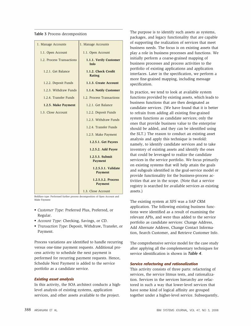
Account and Make Payment subprocesses was
performed to identify candidate services (see
Table 3). Processes and activities from process
decomposition are added to the service model. Some
of these services are also identified during GSM, and
hence can validate the service model.
Information flows through all three constructs of
SOA, namely, service, component, and flows. A
common business glossary is essential so that
everyone in the enterprise can learn to speak the
same terminology, to define a consistent way to
express the business in terms of information, and to
ensure that terms mean the same for all parties.
Business entities identified during functional area
analysis and data flow in the business processes (if
available) are the two key inputs to information
analysis. In addition, existing client information
models and industry models—such as IBM Infor-
mation Framework (IFW), IBM Insurance Applica-
tion Architecture (IAA), ACORD** (Association for
Cooperative Operations Research and Development)
standards for the insurance industry, and TF Forum
Enhanced Telecom Operations Map** (eTOM)—are
also potential inputs. Information life-cycle methods
(create, retrieve, update, and delete) for each of the
key entities might be considered as candidate
information services. In addition, we analyze the
existing information systems and data sources and,
depending on the disparity in the same kinds of
information from multiple data sources, we identify
additional services to provide a consistent view of
the data for the enterprise. The life cycles of
business entities are analyzed for further candidate
services. In the case study, the key business entities
that were identified are: customer, account, product,
transaction, and statement.
The life-cycle methods for these significant business
entities are added as candidate services to the
service portfolio. At XFS there was a need to support
marketing and outreach programs to educate their
existing customers from the insurance and invest-
ment lines of business about the new banking
products and services. A candidate information
service was identified that would make it possible to
search the customer base by factors such as location
and net assets. As result of information analysis, the
following services were added to the service
portfolio: Get Customer, Update Customer, Delete
Customer, Create Account, Get Account, Update
Account, Delete Account, Create Transaction, Get
Transaction, Update Transaction, Delete Transac-
tion, and Search Customer.
Rules and policies drive day-to-day business in the
financial services sector. Rule and policy analysis is
essential when a large number of rules are involved
within the scope. Rules are typically recorded during
process modeling. In rules and policy analysis, we
collect all instances of rules, categorize the rules into
rule types, and identify candidate rule services
based on rule types.
Variation-oriented analysis (VOA) identifies com-
monalities and variations in the process, structure,
data, and rules.12
VOA is a necessary part of service
modeling to ensure reusability and robustness of
service design. Structural variations for XFS were
the following:
Table 2 Functional areas and subsystems
Domains Functional Areas Subsystems
Account service Customer accounting Account management
Financial transaction processing
Billing and payment
Collection recovery
Customer management Customer profile Customer profile
Credit administration
Contact and event history
Boldface type: Domains and functional areas crucial to realize the business goal and corporate strategy
IBM SYSTEMS JOURNAL, VOL 47, NO 3, 2008 ARSANJANI ET AL. 387
� Customer Type: Preferred Plus, Preferred, or
Regular.� Account Type: Checking, Savings, or CD.� Transaction Type: Deposit, Withdraw, Transfer, or
Payment.
Process variations are identified to handle recurring
versus one-time payment requests. Additional pro-
cess activity to schedule the next payment is
performed for recurring payment requests. Hence,
Schedule Next Payment is added to the service
portfolio as a candidate service.
Existing asset analysis
In this activity, the SOA architect conducts a high-
level analysis of existing systems, application
services, and other assets available to the project.
The purpose is to identify such assets as systems,
packages, and legacy functionality that are capable
of supporting the realization of services that meet
business needs. The focus is on existing assets that
play a role in business processes and functions. We
initially perform a coarse-grained mapping of
business processes and process activities to the
portfolio of existing applications and application
interfaces. Later in the specification, we perform a
more fine-grained mapping, including message
specification.
In practice, we tend to look at available system
functions provided by existing assets, which leads to
business functions that are then designated as
candidate services. (We have found that it is better
to refrain from adding all existing fine-grained
system functions as candidate services; only the
ones that provide business value to the enterprise
should be added, and they can be identified using
the SLT.) The reason to conduct an existing asset
analysis and apply this technique is twofold:
namely, to identify candidate services and to take
inventory of existing assets and identify the ones
that could be leveraged to realize the candidate
services in the service portfolio. We focus primarily
on existing systems that will help attain the goals
and subgoals identified in the goal-service model or
provide functionality for the business-process ac-
tivities that are in the scope. (Note that a service
registry is searched for available services as existing
assets.)
The existing system at XFS was a SAP CRM
application. The following existing business func-
tions were identified as a result of examining the
relevant APIs, and were thus added to the service
portfolio as candidate services: Change Address,
Add Alternate Address, Change Contact Informa-
tion, Search Customer, and Retrieve Customer Info.
The comprehensive service model for the case study
after applying all the complementary techniques for
service identification is shown in Table 4.
Service refactoring and rationalization
This activity consists of three parts: refactoring of
services, the service litmus tests, and rationaliza-
tion. Services in the services hierarchy are refac-
tored in such a way that lower-level services that
have some kind of logical affinity are grouped
together under a higher-level service. Subsequently,
Table 3 Process decomposition
1. Manage Accounts 1. Manage Accounts
1.1. Open Account 1.1. Open Account
1.2. Process Transactions 1.1.1. Verify CustomerInfo
1.2.1. Get Balance 1.1.2. Check CreditRating
1.2.2. Deposit Funds 1.1.3. Create Account
1.2.3. Withdraw Funds 1.1.4. Notify Customer
1.2.4. Transfer Funds 1.2. Process Transactions
1.2.5. Make Payment 1.2.1. Get Balance
1.3. Close Account 1.2.2. Deposit Funds
1.2.3. Withdraw Funds
1.2.4. Transfer Funds
1.2.5. Make Payment
1.2.5.1. Get Payees
1.2.5.2. Add Payee
1.2.5.3. Submit
Payment
1.2.5.3.1. Validate
Payment
1.2.5.3.2. Process
Payment
1.3. Close Account
Boldface type: Performed further process decomposition of Open Account and
Make Payment
ARSANJANI ET AL. IBM SYSTEMS JOURNAL, VOL 47, NO 3, 2008388
the SLTs are applied to the set of candidate services
to yield a set of exposed services. The services that
have failed the SLTs will still be implemented as
ordinary functionality within, for example, Sun
Enterprise JavaBeans** or mapped to back-end
legacy systems, but will not be exposed as Web
services. Note that not all services will be imple-
mented in WSDL, but may be deferred to a later
release for this form of implementation. The
functionality will most likely still be required and
will continue to be implemented by traditional
means, but within the context and principles
outlined by SOA. A release plan will include
dependencies between services, components, flows,
information, and rules. Rationalization consists of a
review of the service model with the business
stakeholders to verify the continued relevance of the
services that have been selected for exposure and
subsequently planned for and funded to be built in
the next release.
We categorize or group services by functional areas
to define a service hierarchy and we maintain
parent-child relationships between services in the
hierarchy, later to be used in separating out services
and operations.
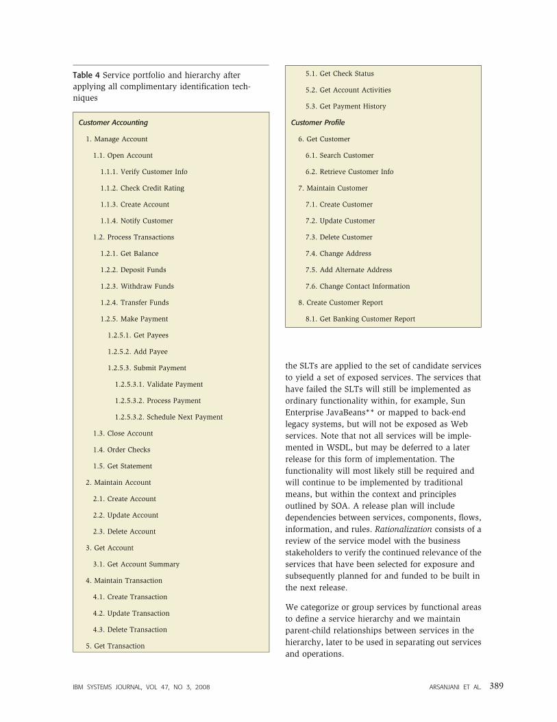
Table 4 Service portfolio and hierarchy after
applying all complimentary identification tech-
niques
Customer Accounting
1. Manage Account
1.1. Open Account
1.1.1. Verify Customer Info
1.1.2. Check Credit Rating
1.1.3. Create Account
1.1.4. Notify Customer
1.2. Process Transactions
1.2.1. Get Balance
1.2.2. Deposit Funds
1.2.3. Withdraw Funds
1.2.4. Transfer Funds
1.2.5. Make Payment
1.2.5.1. Get Payees
1.2.5.2. Add Payee
1.2.5.3. Submit Payment
1.2.5.3.1. Validate Payment
1.2.5.3.2. Process Payment
1.2.5.3.2. Schedule Next Payment
1.3. Close Account
1.4. Order Checks
1.5. Get Statement
2. Maintain Account
2.1. Create Account
2.2. Update Account
2.3. Delete Account
3. Get Account
3.1. Get Account Summary
4. Maintain Transaction
4.1. Create Transaction
4.2. Update Transaction
4.3. Delete Transaction
5. Get Transaction
5.1. Get Check Status
5.2. Get Account Activities
5.3. Get Payment History
Customer Profile
6. Get Customer
6.1. Search Customer
6.2. Retrieve Customer Info
7. Maintain Customer
7.1. Create Customer
7.2. Update Customer
7.3. Delete Customer
7.4. Change Address
7.5. Add Alternate Address
7.6. Change Contact Information
8. Create Customer Report
8.1. Get Banking Customer Report
IBM SYSTEMS JOURNAL, VOL 47, NO 3, 2008 ARSANJANI ET AL. 389
For XFS, we reviewed the service granularity based
on the functional affinity and cohesiveness of the
services. We then refactored, refined, and grouped
the service portfolio in a hierarchy using the two
functional areas, namely, customer accounting and
customer profile (Table 4).
The combined application of technical feasibility
exploration and service refactoring and rationaliza-
tion accelerates SOA projects and helps in focusing
development efforts and resources and in alleviating
risk.
Specification phase
In the SOMA specification phase, the SOA is
designed. High-level design as well as significant
parts of the detailed design of service components is
completed in this phase. During the specification
phase, we leverage the existing assets and further
elaborate the services, flows, and components from
the identification phase in an iterative and incre-
mental fashion to help reach the realization deci-
sion. The service model is further elaborated in
terms of service dependencies, flows and composi-
tion, events, rules and policies, operations, mes-
sages, nonfunctional requirements, and state
management decisions.
We perform two foundational and preparatory
activities before we elaborate and specify the
services, flows, and subsystems (component
boundaries): first, we elaborate and specify infor-
mation models, and second, perform further fine-
grained analysis and specification of existing assets.
Business entities and their high-level structure and
relationships (entity relationship diagrams are rele-
vant to the service scope) are identified during the
identification phase. We elaborate the conceptual
data model into a logical data model to populate the
attributes to be implemented, which must be
defined in terms of their domains or logical data
types (e.g., character, number, date, and picture).
In doing specification, we also focus on the design of
service messages which include input, output, and
error messages. In order to eliminate multiple data
transformations in the service layer, a best practice
is to use a common message model that is accepted
by the enterprise. The model defines the message
flow in the services layer. In the canonical message
model, we select the message format (e.g., Extensi-
ble Markup Language or fixed-length record) and we
define the set of types, elements, and attributes
representing the business entities and their business
attributes. The message types are used as building
blocks for input, output, and error messages for the
services.
Refactoring of existing assets and code in prepara-
tion for making decisions about how to realize a
given service (e.g., with the back-end legacy
application) must be given careful thought and
preparation. We analyze the system interfaces and
the input and output parameters of the existing
systems and perform a fine-grained mapping of the
service to a specific legacy application transaction or
batch process. The mapping provides a potential set
of realization decisions for the SOA. The leveraging
of existing assets through refactoring and mapping
to services is a key aspect of service orientation. For
example, we need to identify duplicate, unstruc-
tured, and unused code before we can rationalize
and encapsulate the functionality to be exposed as a
shared service across channels and consumers.
Service specification
Service specification is the core of the service
modeling activity and focuses on elaborating the
detailed design of the services. The dependencies of
services on other services, components, or applica-
tions, the composition of services, and the flow
among services together define the realization and
choreography of services to enable business func-
tions and processes. Service operations are invoked
to execute a business function in an IT implemen-
tation and hence are a key addition in the service
model. Service operations are designated based on
service granularity, functional affinity, and cohe-
siveness of services in the service hierarchy. When
identifying service operations, we look only for
services in the service hierarchy that are to be
exposed (i.e., those that passed the SLTs). After
service operations are identified, the service hierar-
chy will contain services that will not be exposed as
well as services and their operations that will be
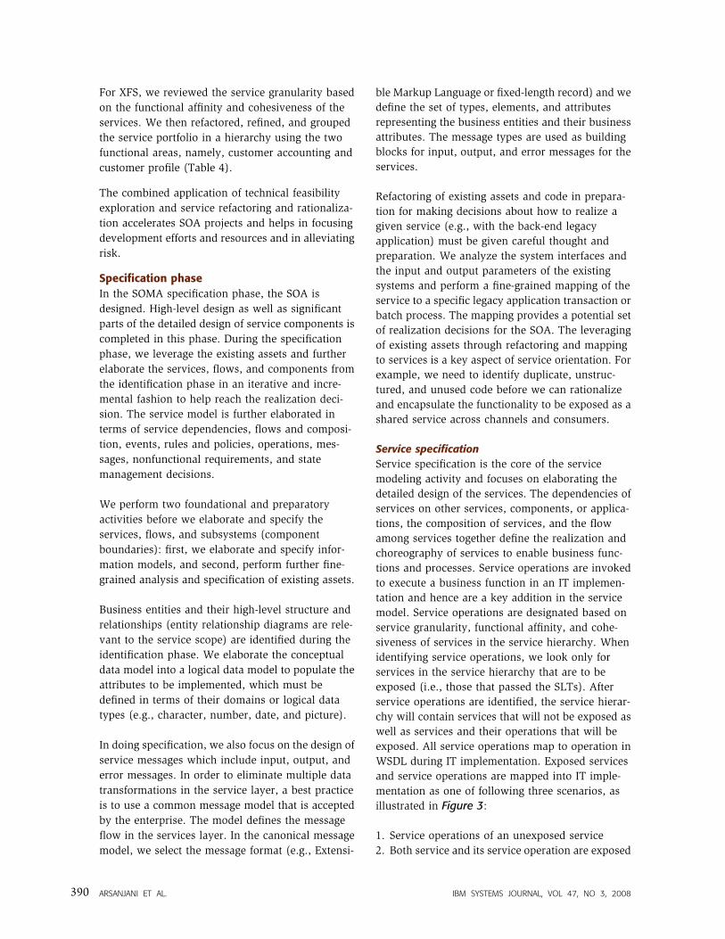
exposed. All service operations map to operation in
WSDL during IT implementation. Exposed services
and service operations are mapped into IT imple-
mentation as one of following three scenarios, as
illustrated in Figure 3:
1. Service operations of an unexposed service
2. Both service and its service operation are exposed
ARSANJANI ET AL. IBM SYSTEMS JOURNAL, VOL 47, NO 3, 2008390
3. Both service and it service operations are exposed
but the parent of the exposed service is a
functional area in the service hierarchy
Service operations are typically described in busi-
ness use cases where requirements are gathered. We
advocate the use of service-cases (see the section
‘‘Paradigm shift from OO to SOA’’ above for more
detail) as an alternative. We specify the nonfunc-
tional requirements affecting the quality of service
(QoS) (e.g., cost of transaction, performance,
availability, and security) for the service and its
operations. The nonfunctional requirements will be
used to commit resources for service components
that offer the services and to fund the realization
and maintenance of service components that will
ensure the delivery of the QoS over time.
We develop a service context diagram depicting the
service ecosystem for a group of related services
illustrating service consumers and service providers
and indicate the flow of messages between services
and the various underlying systems that implement
them. We describe the input, output, and error
messages for a service operation based on a
canonical message model defined earlier. We also
map parameters of service operations to the
parameters of existing asset interfaces so service
operations can be realized by leveraging those
interfaces. We identify the fit gap, specify how to
bridge the gap, and realize the gap using extension,
configuration, and customization in order to lever-
age existing assets.
Although services in SOA are stateless, state
management decisions ensure that the entities acted
upon during the service invocation are at the right
transactional state. We also document invocation
and messaging styles, such as one-way and request-
response, for the services. In a one-way message
exchange pattern, the sender gives a best effort to
WSDL
Service name
Port type name
Operation name
Figure 3Service model mapping into IT implementation as WSDL using three different scenarios, noted in thered numbered boxes
Scenario 2a
Scenario 1
Business/consulting
Scenario 3b
WSDL
Service name
Port type name
Operation name
WSDL
Service name
Port type name
Operation name
Scenario 2b
1
2
3
IT implementation IT implementation
WSDL
Service name
Port type name
Operation name
Operation name
Scenario 3a
WSDL
Service name
Port type name
Operation name
Functional area
Service
Service
Service operationexposed
Service operation
Service
Service operation
Service
Service operation
exposed
exposed
exposed
exposed
exposed
IBM SYSTEMS JOURNAL, VOL 47, NO 3, 2008 ARSANJANI ET AL. 391
move a message from a source location to the
destination. In a request-response message ex-
change pattern, a client asks a service provider a
question and then receives the answer to the
question, which may be a fault or exception.
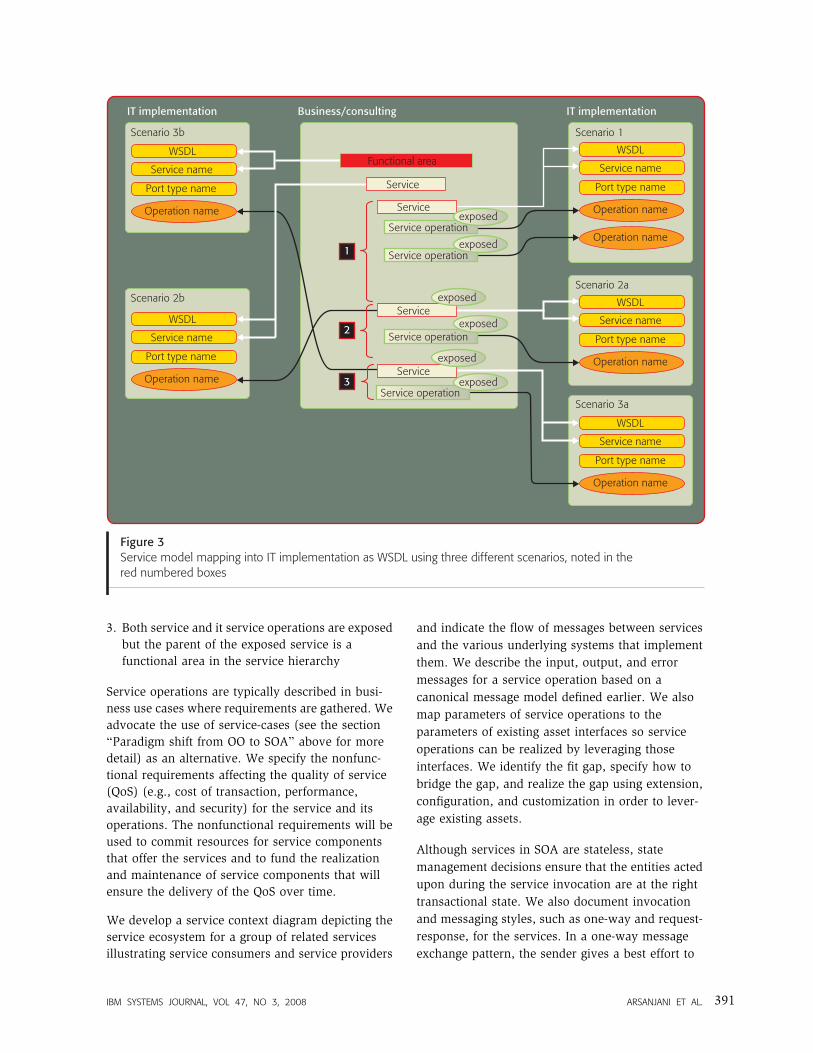
Subsystem analysis
Subsystems signify logical IT boundaries for busi-
ness functionality. Subsystems are identified by
functional decomposition of functional areas. Func-
tional areas and the subsystems that exist in those
functional areas are refined into coarse-grained
service components that are each responsible for a
functional aspect of the subsystem. A major output
of this task is a subsystem dependency diagram that
shows the dependencies of all subsystems and their
interfaces to one another and identifies underlying
existing assets. We typically apply OOAD within the
confine of subsystems to better partition object
graphs with fewer dependencies, as shown in
Figure 4 for XFS. This is in contrast to using OOAD
for the entire system and building traditionally
larger and more unwieldy object associations.
Component specification
During component specification we explore the use
of patterns that can help us to structure service
components into a set of functional components
(supporting business capabilities) and we look for
the technical components responsible for providing
auxiliary support from the perspective of technology
and infrastructure. As we perform OOAD within a
subsystem, we are able to specify the service
components that realize the subsystems. We model
the static and dynamic behavior of service compo-
nents by defining service component interfaces,
developing component diagrams, identifying de-
pendencies on functional and technical components,
and determining the internal flows of the compo-
nents. We select such patterns as the enterprise
component pattern13
to represent the inner structure
of components for each of the service components
and, depending on the complexity and function of
the service components, all or a subset of the
enterprise component pattern is used to generate the
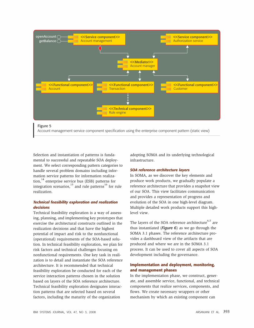
component specification, as shown in Figure 5 for
XFS.
Realization phase
We validate realization decisions by performing
technical feasibility exploration that seeks to exer-
cise the architectural decisions and highest project
risk factors through extensible prototypes designed
and developed early on.
Figure 4Composition of a financial transaction processing subsystem
<<Subsystem>>Financial transaction processing
<<Service component>>Financial transaction processing
<<Functional component>>Payment processing
<<Functional component>>Account
<<Technical component>>Rule engine
<<Functional component>>Customer
<<Technical component>>Reporting engine
<<Functional component>>Transaction
<<Service component>>Financial transaction reporting
ARSANJANI ET AL. IBM SYSTEMS JOURNAL, VOL 47, NO 3, 2008392
Selection and instantiation of patterns is funda-
mental to successful and repeatable SOA deploy-
ment. We select corresponding pattern categories to
handle several problem domains including infor-
mation service patterns for information realiza-
tion,14
enterprise service bus (ESB) patterns for
integration scenarios,15
and rule patterns16
for rule
realization.
Technical feasibility exploration and realization
decisions
Technical feasibility exploration is a way of assess-
ing, planning, and implementing key prototypes that
exercise the architectural constructs outlined in the
realization decisions and that have the highest
potential of impact and risk to the nonfunctional
(operational) requirements of the SOA-based solu-
tion. In technical feasibility exploration, we plan for
risk factors and technical challenges focusing on
nonfunctional requirements. One key task in reali-
zation is to detail and instantiate the SOA reference
architecture. It is recommended that technical
feasibility exploration be conducted for each of the
service interaction patterns chosen in the solution
based on layers of the SOA reference architecture.
Technical feasibility exploration designates interac-
tion patterns that are selected based on several
factors, including the maturity of the organization
adopting SOMA and its underlying technological
infrastructure.
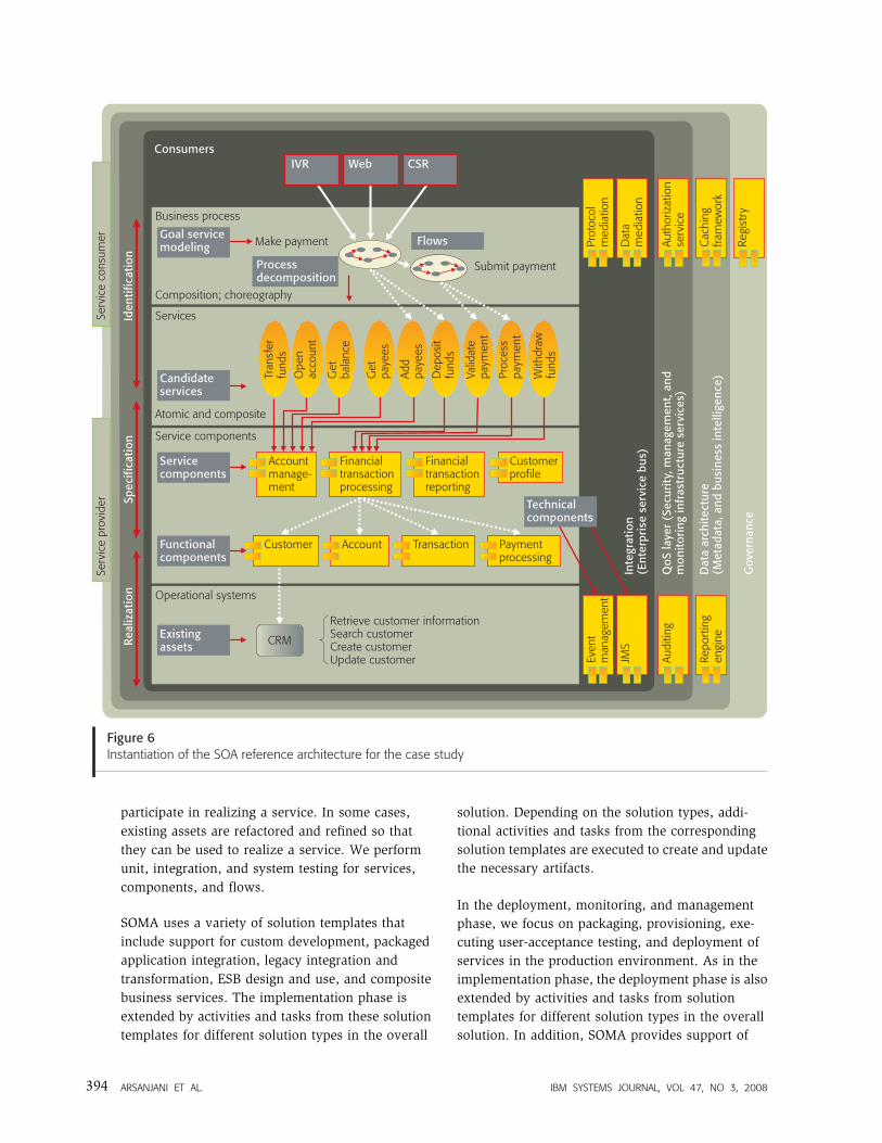
SOA reference architecture layers
In SOMA, as we discover the key elements and
produce work products, we gradually populate a
reference architecture that provides a snapshot view
of our SOA. This view facilitates communication
and provides a representation of progress and
evolution of the SOA in one high-level diagram.
Multiple detailed work products support this high-
level view.
The layers of the SOA reference architecture4,5
are
thus instantiated (Figure 6) as we go through the
SOMA 3.1 phases. The reference architecture pro-
vides a dashboard view of the artifacts that are
produced and where we are in the SOMA 3.1
process. It can be used to cover all aspects of SOA
development including the governance.
Implementation and deployment, monitoring,
and management phases
In the implementation phase, we construct, gener-
ate, and assemble service, functional, and technical
components that realize services, components, and
flows. We create necessary wrappers or other
mechanism by which an existing component can
Figure 5Account management service component specification using the enterprise component pattern (static view)
<<Service component>>Account management
<<Functional component>>Account
<<Technical component>>Rule engine
<<Functional component>>Customer
<<Mediator>>Account manager
<<Service component>>Authorization service
openAccountgetBalance
<<Functional component>>Transaction
IBM SYSTEMS JOURNAL, VOL 47, NO 3, 2008 ARSANJANI ET AL. 393
participate in realizing a service. In some cases,
existing assets are refactored and refined so that
they can be used to realize a service. We perform
unit, integration, and system testing for services,
components, and flows.
SOMA uses a variety of solution templates that
include support for custom development, packaged
application integration, legacy integration and
transformation, ESB design and use, and composite
business services. The implementation phase is
extended by activities and tasks from these solution
templates for different solution types in the overall
solution. Depending on the solution types, addi-
tional activities and tasks from the corresponding
solution templates are executed to create and update
the necessary artifacts.
In the deployment, monitoring, and management
phase, we focus on packaging, provisioning, exe-
cuting user-acceptance testing, and deployment of
services in the production environment. As in the
implementation phase, the deployment phase is also
extended by activities and tasks from solution
templates for different solution types in the overall
solution. In addition, SOMA provides support of
Gov
erna
nce
QoS
laye
r (S
ecur
ity,
man
agem
ent,
and
mon
itor
ing
infr
astr
uctu
re s
ervi
ces)
Inte
grat
ion
(En
terp
rise
ser
vice
bu
s)JM
S
Even
t m
anag
emen
t
Repo
rtin
gen
gine
Audi
ting
Auth
oriz
atio
nse
rvic
e
Dat
am
edia
tion
Regi
stry
Prot
ocol
med
iatio
n
Cac
hing
fram
ewor
kD
ata
arch
itec
ture
(Met
adat
a, a
nd b
usi
ness
inte
llige
nce)
Operational systems
Retrieve customer informationSearch customerCreate customerUpdate customer
Candidate services
Service components
Accountmanage-ment
Customerprofile
Account
Financialtransactionreporting
Transaction Paymentprocessing
Existing assets
Financialtransactionprocessing
CRM
Technical components
Services
Atomic and composite
Ope
n ac
coun
t
Get
bala
nce
Dep
osit
fund
s
Get
pa
yees
Valid
ate
paym
ent
Add
paye
es
Proc
ess
paym
ent
With
draw
fund
s
Tran
sfer
fund
s
Make payment
Business process
Consumers
Composition; choreography
Submit payment
Goal service modeling Flows
Process decomposition
IVR Web CSR
Figure 6Instantiation of the SOA reference architecture for the case study
Serv
ice
prov
ider
Serv
ice
cons
umer
Iden
tific
atio
nSp
ecifi
cati
onR
ealiz
atio
n
Service components
Functional components
Customer
ARSANJANI ET AL. IBM SYSTEMS JOURNAL, VOL 47, NO 3, 2008394
monitoring and management of business processes
and performance monitoring in the production
environment as part of this phase. SOMA also
provides linkages to runtime monitoring and man-
agement aspects, as in system, infrastructure, and
network management.
These later two phases of SOMA—implementation
and deployment, monitoring and management—are
outside the scope of this paper.
CONCLUSIONWe have provided a synopsis of the key concepts,
activities, and tasks pertaining to a service-oriented
software engineering life-cycle method. We have
shown how to conduct service-oriented modeling to
build an SOA by using the IBM SOMA method. This
method has been developed over hundreds of
projects around the world in multiple industries.
SOMA provides a software engineering method for
building end-to-end SOA solutions. We have out-
lined the salient activities and tasks of SOA and
service-oriented modeling based on five years of
multi-industry experience.
A motivation for SOMA, gleaned from hundreds of
architecture, design, and technical reviews of client
projects, suggests that application architectures tend
to be brittle and inflexible (for a variety of reasons
which are beyond the scope of this paper).
However, what we learned is that the construct of a
service can be used to further realize proper
separation of concerns, resulting in IT architectures
that are easier to maintain and costs that are lower.
We know there is no single easy solution,5
but at the
same time we have learned that IT organizations can
incrementally move IT architectures to reflect
increased loose coupling and to make technology
better represent how the business works and allow
the business to respond to change on its terms.
SOMA provides the detailed guidance for making
this goal achievable.
SOMA has a rich WBS that comprises activities,
tasks, and corresponding inputs and outputs. Scopes
for the enterprise can scale down to the simple
project testing of new Web services. It can be
configured to be leaner (SOMA Agile), to support
projects focused solely on integration or testing Web
services, or it can be configured to a more rigorous
method supporting business- or enterprise-wide
transformations (SOMA Complete). SOMA can be
used to support identification and prioritization of
high-priority services or it can be used to develop an
application or system adopting SOA.
Any project that adopts object orientation and
component-based development as part of its soft-
ware engineering practices should adopt the con-
struct of a service and its corresponding
identification, specification, and realization tech-
niques as a software engineering best practice.
Whether or not the service is exposed to external
partners is simply an architectural or business
decision; however, the service construct promotes
improved and recombinant separation of concerns
of components and objects in a manner that is not
presently done with other approaches.
SOA-based solutions will benefit from using the
prescriptive guidance provided as part of SOMA.
SOMA has a fractal life-cycle model that is used in
successive iterations of service releases, which
makes it possible for solutions to evolve beyond the
more traditional iterative and incremental changes.
ACKNOWLEDGMENTSMany people at IBM worldwide have contributed to
the ideas and concepts represented in SOMA, and
they are too numerous to identify individually, but
we are appreciative of all of them. SOMA would not
have been possible without the contributions of our
esteemed colleagues.
**Trademark, service mark, or registered trademark of ObjectManagement Group, Inc, Sun Microsystems, Inc., ACORDCorporation, or TeleManagement Forum Corporation in theUnited States, other countries, or both.
CITED REFERENCES1. D. L. Parnas, ‘‘On the Criteria to be Used in Decomposing
Systems into Modules,’’ Communications of the ACM 15,No. 12, 1053–1058 (1972).
2. G. Booch, J. Rumbaugh, and I. Jacobson, The UnifiedModeling Language User Guide, Addison-Wesley, Boston(1999).
3. E. Gamma, R. Helm, R. Johnson, and J. Vlissides, DesignPatterns: Elements of Reusable Object-Oriented SoftwareArchitecture, Addison-Wesley Professional, Boston(1995).
4. A. Arsanjani, L.-J. Zhang, M. Ellis, A. Allam, and K.Channabasavaiah, ‘‘S3: A Service-Oriented ReferenceArchitecture,’’ IEEE IT Professional 9, No. 3, 10–17(2007).
5. A. Arsanjani, L.-J. Zhang, M. Ellis, A. Allam, and K.Channabasavaiah, ‘‘Design an SOA Solution Using aReference Architecture,’’ IBM developerWorks, IBM
IBM SYSTEMS JOURNAL, VOL 47, NO 3, 2008 ARSANJANI ET AL. 395
Corporation (2007), http://www.ibm.com/developerworks/library/ar-archtemp/.
6. O. Zimmerman, P. Krogdahl, and C. Gee, ‘‘Elements ofService-Oriented Analysis and Design,’’ IBM developer-Works, IBM Corporation (2004), http://www.ibm.com/developerworks/library/ws-soad1/.
7. A. Arsanjani and K. Holley, ‘‘The Service IntegrationMaturity Model: Achieving Flexibility in the Transfor-mation to SOA,’’ Proceedings of the IEEE InternationalConference on Services Computing, Chicago (2006),pp. 515.
8. A. Arsanjani, ‘‘Service-oriented Modeling and Architec-ture: How to Identify, Specify and Realize Services forYour SOA,’’ IBM developerWorks, IBM Corporation(2004), http://www.ibm.com/developerworks/library/ws-soa-design1/.
9. R. Varadan, K. Channabasavaiah, S. Simpson, K. Holley,and A. Allam, ‘‘Increasing Business Flexibility and SOAAdoption Through Effective SOA Governance,’’ IBMSystems Journal 47, No. 3, 473–488 (2008, this issue).
10. B. W. Boehm, ‘‘A Spiral Model of Software Developmentand Enhancement,’’ IEEE Computer 21, No. 5, 61–72(1988).
11. L. Bass, P. Clements, and R. Kazman, Software Architec-ture in Practice, Addison-Wesley Professional, Boston(1998).
12. L.-J. Zhang, A. Arsanjani, A. Allam, D. Lu, and Y.-M.Chee, Proceedings of the IEEE International Conference onServices Computing,‘‘Variation-Oriented Analysis for SOASolution Design,’’ Salt Lake City, UT, (2007),pp. 560–568.
13. K. Levi and A. Arsanjani, ‘‘A Goal-driven Approach toEnterprise Component Identification and Specification,’’Communications of the ACM 45, No. 10, 45–52 (2002).
14. G. Sauter, B. Mathews, M. Selvage, and E. Lane,‘‘Information Service Patterns, Part 1: Data FederationPattern,’’ IBM developerWorks, IBM Corporation (2006),http://www-128.ibm.com/developerworks/webservices/library/ws-soa-infoserv1/.
15. M. Keen, O. Adinolfi, S. Hemmings, A. Humphreys, H.Kanthi, and A. Nottingham, ‘‘Patterns: SOA with anEnterprise Service Bus in WebSphere Application ServerV6,’’ IBM Redbooks (2005), http://www.redbooks.ibm.com/abstracts/sg246494.html.
16. A. Arsanjani, ‘‘Rule Object 2001: A Pattern Language forAdaptive and Scalable Business Rule Construction,’’Proceedings of the 8th Conference on Pattern Languages ofPrograms, Monticello, IL (2001), http://jerry.cs.uiuc.edu/;plop/plop2001/accepted_submissions/PLoP2001/AArsanjani1/PLoP2001_AArsanjani1_0.pdf.
Accepted for publication February 7, 2008.
Ali ArsanjaniIBM Global Business Services, 625 32nd Avenue SW, Suite 130,Cedar Rapids, IA 52404 ([email protected]). Dr. Arsanjaniis an IBM Distinguished Engineer and Chief TechnicalOfficer, Emerging SOA Technologies, supporting larger IBMclients in complex, distributed projects. He leads the 6000-member IBM SOA Community of Practice and is a member ofthe IEEE and the IBM Academy of Technology. He received aPh.D. degree in computer science and engineering fromDeMontfort University, U.K.
Shuvanker GhoshIBM Global Business Services, 3031 N. Rocky Point Drive West,Tampa, FL 33607 ([email protected]). Mr. Ghosh is amember of the SOA and Web Services Center of Excellence,supporting IBM clients in financial services and health care.He is a member of the IBM SOMA team. His interests includeSOA, industry models, assets and solution, component-baseddevelopment, and distributed computing. He received a B.S.degree in mechanical engineering from the Indian Institute ofTechnology (IIT), India, and an M.S. degree in mechanicalengineering from the University of Maryland at College Park.
Abdul AllamIBM Global Business Services, 3100 Smoketree Court, Raleigh,NC 27604 ([email protected]). Mr. Allam is a certifiedexecutive IT architect in application development practice. Hehas published several papers on SOA and SOA referencearchitecture for IBM developerWorks and IEEE publications.His current focus is developing SOA estimation models, SOAreference architecture, and context-aware services. He holdsan M.S. degree in systems science and an M.B.A. degree, bothfrom the University of Ottawa.
Tina AbdollahIBM Global Business Services, 100 N. Sepulveda Boulevard, ElSegundo, CA 90245 ([email protected]). Ms. Abdollah isa certified executive IT architect in the Enterprise andArchitecture Technology practice. She is a member of the SOAand Web Services Center of Excellence and SOMA and SOAacceleration teams. She was awarded the 2007 EA&T BestEfforts Award, the 2007 National Women of Color TechnologyAll-Stars Award, and an IBM developerWorks Author Award.She received a B.S. degree in economics from the NationalCheng-chi University of the Republic of China, a B.S. degree incomputer information science from Santa Monica College, andan M.S. degree in library and information science from theUniversity of California at Los Angeles.
Sella GanapathyIBM Global Business Services, 4400 N. 1st Street, Suite 100, SanJose, CA 95134 ([email protected]). Mr. Ganapathy is asenior IT architect and senior certified IT specialist and amember of the IBM SOMA team. His interest is in developingand deploying the SOMA method for implementing SOAs. Healso has expertise in enterprise application integration. Hereceived an M.S. degree in industrial engineering from the Dr.Ambedkar Institute of Productivity, India, and a B.S. degree inchemical engineering from Annamalai University, India.
Kerrie HolleyIBM Global Business Services, 425 Market Street, SanFrancisco, CA 94105 ([email protected]). Mr. Holley is anIBM Fellow. He is the chief technical officer (CTO) of the IBMSOA CoE and a member of the IBM Academy of Technology.His responsibilities include technical leadership for SOAprojects, architecture and design, technical oversight,enterprise architecture design, and IT strategy. As CTO, he isresponsible for IBM SOA delivery methods and related tools.His focus is on helping customers realize the sustainedbenefits of applying SOA. As an IBM Fellow, he helps defineIBM SOA strategy and direction. He has a B.A. degree inmathematics from DePaul University and a J.D. degree in lawfrom the DePaul School of Law. &
ARSANJANI ET AL. IBM SYSTEMS JOURNAL, VOL 47, NO 3, 2008396
Published online August 6, 2008.