Embed Size (px)
Citation preview
8/13/2019 Som Manuals 2005
http://slidepdf.com/reader/full/som-manuals-2005 1/22
INDEXSTRENGTH OF MATERIAL LAB (ME-215E)
8/13/2019 Som Manuals 2005
http://slidepdf.com/reader/full/som-manuals-2005 2/22
AIM: To find out Brinell Hardness Number of given test piece.
REQUIREMENTS:1. Brinell Hardness Tester
2. Test Piece3. Hardened steel ball 10mm diameter 4. icroscope
THEORY:Hardness represents t!e resistance of a material to indentation" and involves t!emeasurement of plastic deformation caused #!en a loaded ball or diamond is appliedto t!e surface of material.Brinell et!od: $n t!is a !ardened steel ball is pressed into t!e surface under aspecified load #!ic! is !eld on for a fi%ed period and t!en released.Brinell Hardness is defined as t!e &uotient of t!e applied force '" divided b( t!e
sp!erical area of impression.'rom fig......... #e find t!at:Brinell Hardness" HB ) Test load*+urface area of indentation
) 2'*,--/-/d N*mm
PROCEDURE:1. Place t!e test specimen and t!e test table of t!e testing mac!ine.2. ppl( load slo#l( and progressivel( to t!e specimen at rig!t angle to t!e surfaceand maintain full load for 1 seconds.3. 5elease t!e load and remove t!e specimen from t!e table.4. easure t!e diameter of impression on t!e test specimen b( microscope fitted #it!a scale.
6B+758T$6N+:aterial of test piece )-iameter of ball )9oad ' )9oad application time )-iameter of $mpression d )
;9;<9T$6N+:Brinell Hardness HB )Test load=+urface area of indentation
) 2'=,--/-/d N=mm
P57;<T$6N+:1. T!e surface of test piece s!ould be smoot! and test spot free of oil and dirt s!ould
be polis!ed to get a clear impression.2. T!e load value of indenter diameter s!ould be selected from table 1 depending

8/13/2019 Som Manuals 2005
http://slidepdf.com/reader/full/som-manuals-2005 3/22
upon material of test specimen of its t!ic>ness.
RESULT:Brinell Hardness )
8/13/2019 Som Manuals 2005
http://slidepdf.com/reader/full/som-manuals-2005 4/22
Haryana EngineeringCollege
-oc.: H7;*7;H*7/217*+/3*P/2
Exp!"#$% I$&%!'%"$& $ssue: 01
Page No.: 1 of 2
AIM:To stud( t!e $mpact Testing ac!ine ? perform t!e $mpact Test $@od ? ;!arp(.
REQUIREMENTS:1. $mpact Testing ac!ine2. +pecimen
THEORY:I#p*% T&%: T!e test is to determine t!e be!avior of materials #!en subAected tosudden loading.C+*!p, I#p*% T&%: $t is single blo# $mpact test" in #!ic! t!e notc!ed specimen issupported at bot! ends" as a simple beam ? bro>en b( a falling pendulum on faceopposite to and immediatel( be!ind t!e notc!.I. I#p*% T&%: $t is a single blo# $mpact test" in #!ic! t!e notc!ed specimen isfi%ed at one end and bro>en b( a falling pendulum.$mpact +trengt!: 7nerg( absorbed b( specimen during impact test is >no#n as impactstrengt!.
PROCEDURE:
1. +et t!e needle of scale at @ero position.2. 5aise t!e pendulum P >g to an appropriate !eig!t !1. !1 depends upon energ(stored 300 N/m.3. 9ocate t!e specimen on its proper place according to test.4. Pendulum is dropped freel( from !eig!t !1. T!e pendulum #ill brea> t!e testspecimen and s!oot up to t!e ot!er side of t!e mac!ine.. T!e pendulum is stopped #it! t!e !elp of bro>en operated b( a lever.. 5esidual energ( indicated on t!e scale b( t!e pendulum is noted.C. T!e impact strengt! of t!e test piece is t!e difference of t!e initial energ( stored int!e !ammer and t!e residual energ(.
;9;<9T$6N:$mpact +trengt! 7 ) 71/72 ) P!1/!2 >gmD!ere 71 ) 7nerg( stored before $mpact
72 ) 7nerg( stored after $mpact.
8/13/2019 Som Manuals 2005
http://slidepdf.com/reader/full/som-manuals-2005 5/22
6B+758T$6N:aterial of test piece:-imension of test piece:$nitial 7nerg( 71:5esidual 7nerg( 72:
P57;<T$6N+:1. 6ne s!ould not stand in t!e s#inging line of pendulum.2. Hammer s!ould be in loc>ing position #!en t!e specimen is being placed fortesting.3. Eeep t!e mac!ine in loc>ing position after t!e practical is over.
RESULT:$mpact +trengt! of specimen ) //////// >gm
8/13/2019 Som Manuals 2005
http://slidepdf.com/reader/full/som-manuals-2005 6/22
AIM:To stud( t!e <niversal Testing ac!ine ? perform t!e Tensile Test.
REQUIREMENTS:
1. <niversal Testing ac!ine2. Test specimen3. icrometer 4. +teel scale
THEORY:D!en a metal piece is loaded b( tensile force" metal piece get strained due to #!ic!tensile stress is induced in test specimen.Tensile test consists in straining a test piece
b( tensile stress" generall( to fracture" #it! a vie# of determining one or more of t!econtinusl( properties.T!is test is done on <T.
<T:T!is mac!ine is consists of t!ree cross !eads.<pper ? 9o#er cross !eads arerigidl( connected to columns. 9o#er cross !eads is connected to t!e #or>ing piston ?t!ird cross !ead can be moved up #it! t!e !elp of motor b( rotating t!e t!readedspindles. +pecimen is fi%ed bet#een t#o cross !eads according to tensile orcompression test.
PROCEDURE:1. T!e diameter of t!e test piece is measured b( means of a micrometer at least att!ree plane and determine t!e mean value. T!e gauge lengt! is mar>ed.2. +uitable scale is selected.3. T!e test specimen in t!e grips is inserted b( adAusting t!e cross/!eads of t!emac!ine.4. 'i% t!e e%tensometer on t!e test piece and set its scale dials to @ero position.. Frap! recording s(stem is activated.. ac!ine is started and readings of dials on t!e e%tensometer is ta>en for a
particular value of load.C. T!e rate of loading ma( be 10 mpc*sec initiall( and s!ould be reduced toC.mpc*sec. #!en t!e (ield point is reac!ed.G. 9oad is applied continuousl( till t!e specimen brea>s and t!en stop t!e mac!ine.. Plot load vs e%tension diagram.
6B+758T$6N:9.;. of micrometer )
6riginal dia. of specimen d )-ia after fracture du )Fauge lengt! 9o )Total lengt! after fracture 9u )9.;. of e%tensometer )
8/13/2019 Som Manuals 2005
http://slidepdf.com/reader/full/som-manuals-2005 7/22
;9;<9T$6N+:+tress +trengt! ) 9oad*reaPercentage elongation ) 1009u/9o*9oPercentage reduction in area ) 100+u/+o*+o
RESULTS:Proportional limit" Pa )Iield strengt!" pa )<ltimate +trengt!" Pa )Brea>ing strengt!" Pa )odulus of elasticit( )FPaPercentage elongation )Percentage reduction in area )
8/13/2019 Som Manuals 2005
http://slidepdf.com/reader/full/som-manuals-2005 8/22
AIM:To perform ;ompression test ? find out t!e compressive strengt! of test piece.
REQUIREMENTS:
1. <niversal Testing ac!ine2. Test piece
THEORY:;ompression Test consists in straining a test piece b( compression loading. +pecimenfor compression test on metal are usuall( circular" and for concrete s&uare" in/section.To prevent failure b( bul>ing" t!e lengt! s!ould be of about t!e same order as t!eminimum #idt!. $n t!e ductile material distortion ta>es place #!ile in case of brittlematerials" usuall( fail b( s!earing.
PROCEDURE:
1. easure t!e diameter of t!e test piece at t!ree different planes and ta>e t!eaverage value.2. Place t!e specimen bet#een middle and lo#er cross !eads and appl( t!ecompressive load.3. $ncrease t!e load graduall( until t!e specimen fails.
6B+758T$6N+:<ltimate load )verage diameter of test piece - );9;<9T$6N+:;ross/sectional area )<ltimate compressive strengt! )
P57;<T$6N+:1. T!e specimen s!ould be straig!t and ends of specimen must be at rig!t angle to t!ea%is of specimen.2. T!e lengt! of specimen !as to be >ept small to avoid t!e buc>ling of t!e specimen.
RESULT:<ltimate ;ompressive +trengt! )
8/13/2019 Som Manuals 2005
http://slidepdf.com/reader/full/som-manuals-2005 9/22
8/13/2019 Som Manuals 2005
http://slidepdf.com/reader/full/som-manuals-2005 10/22
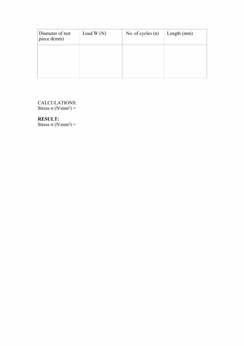
-iameter of test piece dmm
9oad D N No. of c(cles n 9engt! mm
;9;<9T$6N+:+tress J N=mm )
RESULT:+tress J N=mm )
8/13/2019 Som Manuals 2005
http://slidepdf.com/reader/full/som-manuals-2005 11/22
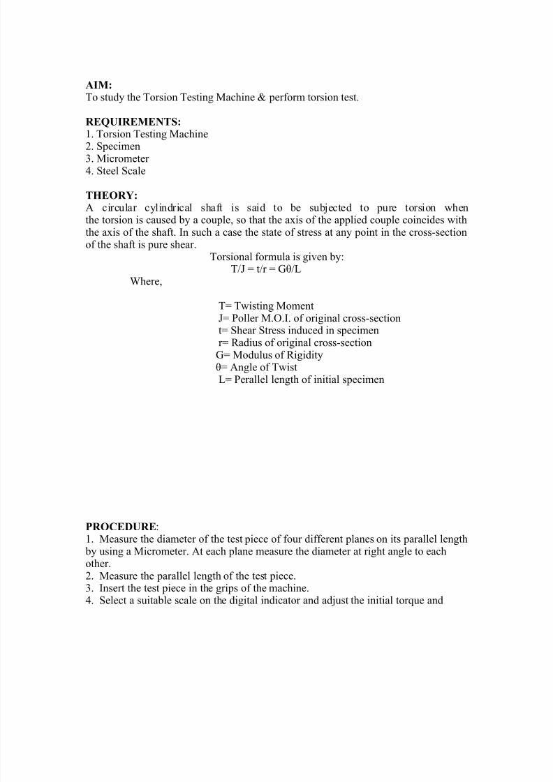
AIM:To stud( t!e Torsion Testing ac!ine ? perform torsion test.
REQUIREMENTS:
1. Torsion Testing ac!ine2. +pecimen3. icrometer 4. +teel +cale
THEORY: circular c(lindrical s!aft is said to be subAected to pure torsion #!ent!e torsion is caused b( a couple" so t!at t!e a%is of t!e applied couple coincides #it!t!e a%is of t!e s!aft. $n suc! a case t!e state of stress at an( point in t!e cross/sectionof t!e s!aft is pure s!ear.
Torsional formula is given b(:
T*K ) t*r ) FL*9D!ere"
T) T#isting oment K) Poller .6.$. of original cross/section t) +!ear +tress induced in specimen r) 5adius of original cross/section F) odulus of 5igidit( L) ngle of T#ist 9) Perallel lengt! of initial specimen
PROCEDURE:1. easure t!e diameter of t!e test piece of four different planes on its parallel lengt!
b( using a icrometer. t eac! plane measure t!e diameter at rig!t angle to eac!ot!er.2. easure t!e parallel lengt! of t!e test piece.3. $nsert t!e test piece in t!e grips of t!e mac!ine.4. +elect a suitable scale on t!e digital indicator and adAust t!e initial tor&ue and
8/13/2019 Som Manuals 2005
http://slidepdf.com/reader/full/som-manuals-2005 12/22
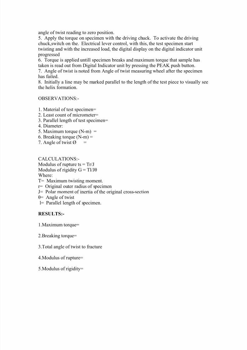
angle of t#ist reading to @ero position.. ppl( t!e tor&ue on specimen #it! t!e driving c!uc>. To activate t!e drivingc!uc>"s#itc! on t!e. 7lectrical lever control" #it! t!is" t!e test specimen startt#isting and #it! t!e increased load" t!e digital displa( on t!e digital indicator unit
progressed
. Tor&ue is applied untill specimen brea>s and ma%imum tor&ue t!at sample !asta>en is read out from -igital $ndicator unit b( pressing t!e P7E pus! button.C. ngle of t#ist is noted from ngle of t#ist measuring #!eel after t!e specimen!as failed.G. $nitiall( a line ma( be mar>ed parallel to t!e lengt! of t!e test piece to visuall( seet!e !eli% formation.
6B+758T$6N+:/
1. aterial of test specimen)2. 9east count of micrometer)
3. Parallel lengt! of test specimen)4. -iameter:. a%imum tor&ue N/m ). Brea>ing tor&ue N/m )C. ngle of t#ist M )
;9;<9T$6N+:/odulus of rupture ts ) Tr*Kodulus of rigidit( F ) Tl*KLD!ere:T) a%imum t#isting moment.r) 6riginal outer radius of specimenK) Polar moment of inertia of t!e original cross/sectionL) ngle of t#ist l) Parallel lengt! of specimen.
RESULTS:-
1.a%imum tor&ue)
2.Brea>ing tor&ue)
3.Total angle of t#ist to fracture
4.odulus of rupture)
.odulus of rigidit()
8/13/2019 Som Manuals 2005
http://slidepdf.com/reader/full/som-manuals-2005 13/22
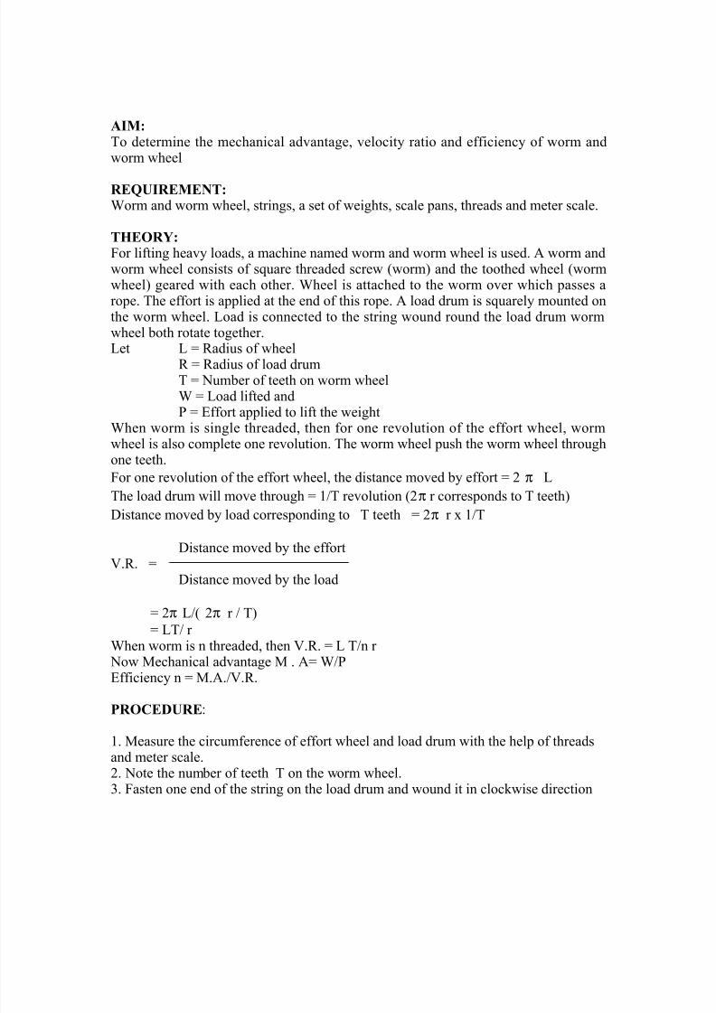
AIM:To determine t!e mec!anical advantage" velocit( ratio and efficienc( of #orm and#orm #!eel
REQUIREMENT:Dorm and #orm #!eel" strings" a set of #eig!ts" scale pans" t!reads and meter scale.
THEORY:'or lifting !eav( loads" a mac!ine named #orm and #orm #!eel is used. #orm and#orm #!eel consists of s&uare t!readed scre# #orm and t!e toot!ed #!eel #orm#!eel geared #it! eac! ot!er. D!eel is attac!ed to t!e #orm over #!ic! passes arope. T!e effort is applied at t!e end of t!is rope. load drum is s&uarel( mounted ont!e #orm #!eel. 9oad is connected to t!e string #ound round t!e load drum #orm#!eel bot! rotate toget!er.
9et 9 ) 5adius of #!eel5 ) 5adius of load drumT ) Number of teet! on #orm #!eelD ) 9oad lifted andP ) 7ffort applied to lift t!e #eig!t
D!en #orm is single t!readed" t!en for one revolution of t!e effort #!eel" #orm#!eel is also complete one revolution. T!e #orm #!eel pus! t!e #orm #!eel t!roug!one teet!.'or one revolution of t!e effort #!eel" t!e distance moved b( effort ) 2 π 9T!e load drum #ill move t!roug! ) 1*T revolution 2π r corresponds to T teet!-istance moved b( load corresponding to T teet! ) 2π r % 1*T
-istance moved b( t!e effort8.5. )
-istance moved b( t!e load
) 2π 9* 2π r * T ) 9T* r D!en #orm is n t!readed" t!en 8.5. ) 9 T*n r
No# ec!anical advantage . ) D*P7fficienc( n ) ..*8.5.
PROCEDURE:
1. easure t!e circumference of effort #!eel and load drum #it! t!e !elp of t!readsand meter scale.2. Note t!e number of teet! T on t!e #orm #!eel.3. 'asten one end of t!e string on t!e load drum and #ound it in cloc>#ise direction
8/13/2019 Som Manuals 2005
http://slidepdf.com/reader/full/som-manuals-2005 14/22
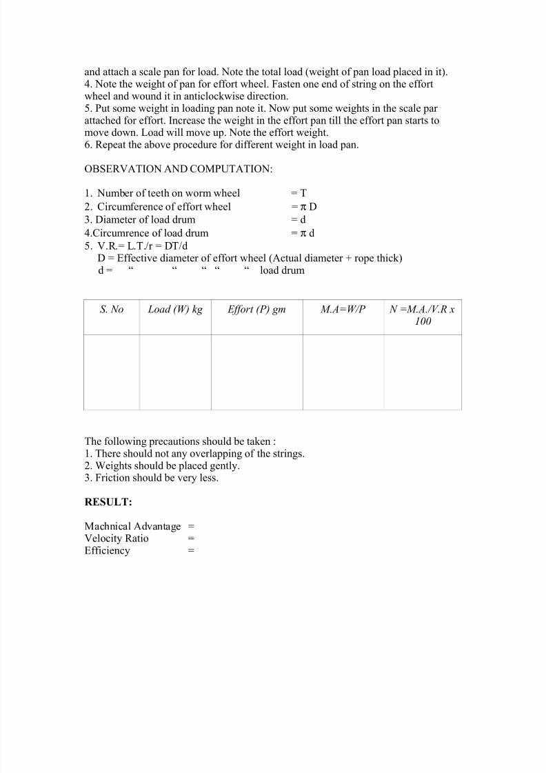
and attac! a scale pan for load. Note t!e total load #eig!t of pan load placed in it.4. Note t!e #eig!t of pan for effort #!eel. 'asten one end of string on t!e effort#!eel and #ound it in anticloc>#ise direction.. Put some #eig!t in loading pan note it. No# put some #eig!ts in t!e scale parattac!ed for effort. $ncrease t!e #eig!t in t!e effort pan till t!e effort pan starts to
move do#n. 9oad #ill move up. Note t!e effort #eig!t.. 5epeat t!e above procedure for different #eig!t in load pan.
6B+758T$6N N- ;6P<TT$6N:
1. Number of teet! on #orm #!eel ) T2. ;ircumference of effort #!eel ) π -3. -iameter of load drum ) d4.;ircumrence of load drum ) π d. 8.5.) 9.T.*r ) -T*d
- ) 7ffective diameter of effort #!eel ctual diameter rope t!ic>
d ) O O O O O load drum
S. No Load (W) kg Effort (P) gm M.A=W/P N =M.A./V.R x100
T!e follo#ing precautions s!ould be ta>en :1. T!ere s!ould not an( overlapping of t!e strings.2. Deig!ts s!ould be placed gentl(.3. 'riction s!ould be ver( less.
RESULT:
ac!nical dvantage )
8elocit( 5atio )7fficienc( )
8/13/2019 Som Manuals 2005
http://slidepdf.com/reader/full/som-manuals-2005 15/22
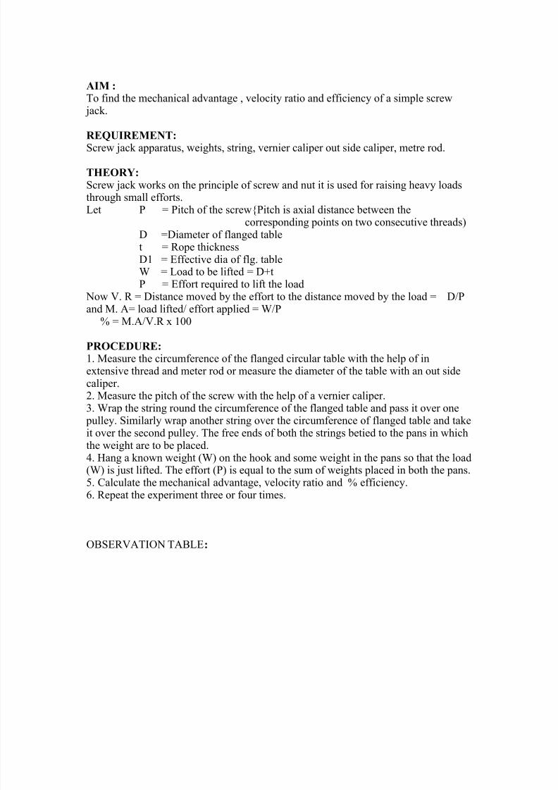
AIM :To find t!e mec!anical advantage " velocit( ratio and efficienc( of a simple scre#
Aac>.
REQUIREMENT:+cre# Aac> apparatus" #eig!ts" string" vernier caliper out side caliper" metre rod.
THEORY:+cre# Aac> #or>s on t!e principle of scre# and nut it is used for raising !eav( loadst!roug! small efforts.9et P ) Pitc! of t!e scre#Pitc! is a%ial distance bet#een t!e
corresponding points on t#o consecutive t!reads- )-iameter of flanged tablet ) 5ope t!ic>ness-1 ) 7ffective dia of flg. table
D ) 9oad to be lifted ) -tP ) 7ffort re&uired to lift t!e load No# 8. 5 ) -istance moved b( t!e effort to t!e distance moved b( t!e load ) -*Pand . ) load lifted* effort applied ) D*P Q ) .*8.5 % 100
PROCEDURE: 1. easure t!e circumference of t!e flanged circular table #it! t!e !elp of ine%tensive t!read and meter rod or measure t!e diameter of t!e table #it! an out sidecaliper.2. easure t!e pitc! of t!e scre# #it! t!e !elp of a vernier caliper.3. Drap t!e string round t!e circumference of t!e flanged table and pass it over one
pulle(. +imilarl( #rap anot!er string over t!e circumference of flanged table and ta>eit over t!e second pulle(. T!e free ends of bot! t!e strings betied to t!e pans in #!ic!t!e #eig!t are to be placed.4. Hang a >no#n #eig!t D on t!e !oo> and some #eig!t in t!e pans so t!at t!e loadD is Aust lifted. T!e effort P is e&ual to t!e sum of #eig!ts placed in bot! t!e pans.. ;alculate t!e mec!anical advantage" velocit( ratio and Q efficienc(.. 5epeat t!e e%periment t!ree or four times.
6B+758T$6N TB97:
8/13/2019 Som Manuals 2005
http://slidepdf.com/reader/full/som-manuals-2005 16/22
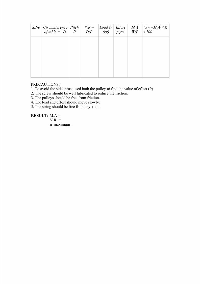
S.No Circmf!r!"c!of ta#$! = %
Pitc& P
V.R = %/P
Load W(kg)
Effort ' gm
M.AW/P
" =M.A/V.R x 100
P57;<T$6N+:1. To avoid t!e side t!rust used bot! t!e pulle( to find t!e value of effort.P2. T!e scre# s!ould be #ell lubricated to reduce t!e friction.
3. T!e pulle(s s!ould be free from friction.4. T!e load and effort s!ould move slo#l(.. T!e string s!ould be free from an( >not.
RESULT: . )8.5 )n ma%imum)
8/13/2019 Som Manuals 2005
http://slidepdf.com/reader/full/som-manuals-2005 17/22
Haryana EngineeringCollege
-oc.: H7;*7;H*7/217*+/3*P/
Exp!"#$% I$&%!'%"$& $ssue: 01
Page No.: 1 of 3
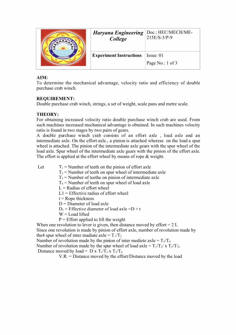
AIM: To determine t!e mec!anical advantage" velocit( ratio and efficienc( of double
purc!ase crab #inc!.
REQUIREMENT: -ouble purc!ase crab #inc!" strings" a set of #eig!t" scale pans and metre scale.
THEORY:
'or obtaining increased velocit( ratio double purc!ase #inc! crab are used. 'romsuc! mac!ines increased mec!anical advantage is obtained. $n suc! mac!ines velocit(ratio is found in t#o stages b( t#o pairs of gears. double purc!ase #inc! crab consists of an effort a%le " load a%le and anintermediate a%le. 6n t!e effort a%le." a pinion is attac!ed #!ereas on t!e load a spur#!eel is attac!ed. T!e pinion of t!e intermediate a%le gears #it! t!e spur #!eel of t!eload a%le. +pur #!eel of t!e intermediate a%le gears #it! t!e pinion of t!e effort a%le.T!e effort is applied at t!e effort #!eel b( means of rope ? #eig!t.
9et T1 ) Number of teet! on t!e pinion of effort a%le T2 ) Number of teet! on spur #!eel of intermediate a%le
T3 ) Number of teet!e on pinion of intermediate a%leT4 ) Number of teet! on spur #!eel of load a%le9 ) 5adius of effort #!eel91 ) 7ffective radius of effort #!eelt ) 5ope t!ic>ness- ) -iameter of load a%le-1 ) 7ffective diameter of load a%le )- tD ) 9oad liftedP ) 7ffort applied to lift t!e #eig!t
D!en one revolution to lever is given" t!en distance moved b( effort ) 2 9+ince one revolution is made b( pinion of effort a%le" number of revolution made b(
t!e4 spur #!eel of inter madiate a%le ) T1*T2
Number of revolution made b( t!e pinion of inter mediete a%le ) T3*T4
Number of revolution made b( t!e spur #!eel of load a%le ) T1*T2* % T3*T*4
-istance moved b( load ) - % T1*T2 % T3*T4
8.5. ) -istance moved b( t!e effort*-istance moved b( t!e load
8/13/2019 Som Manuals 2005
http://slidepdf.com/reader/full/som-manuals-2005 18/22
No# ec!anical advantage ..) D*P7fficfinc( n ) ..*8.5.
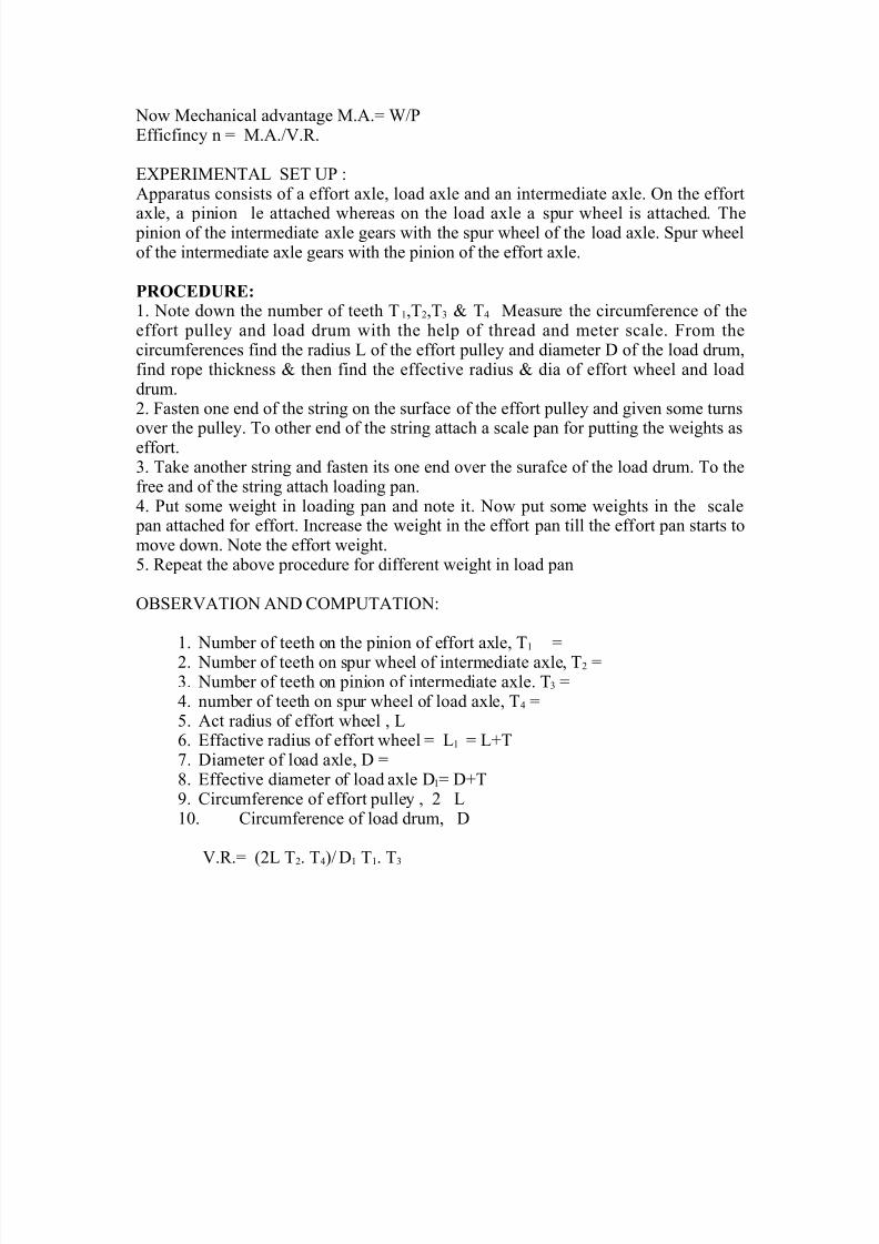
7RP75$7NT9 +7T <P :pparatus consists of a effort a%le" load a%le and an intermediate a%le. 6n t!e effort
a%le" a pinion le attac!ed #!ereas on t!e load a%le a spur #!eel is attac!ed. T!e pinion of t!e intermediate a%le gears #it! t!e spur #!eel of t!e load a%le. +pur #!eelof t!e intermediate a%le gears #it! t!e pinion of t!e effort a%le.
PROCEDURE:1. Note do#n t!e number of teet! T1"T2"T3 ? T4 easure t!e circumference of t!eeffort pulle( and load drum #it! t!e !elp of t!read and meter scale. 'rom t!ecircumferences find t!e radius 9 of t!e effort pulle( and diameter - of t!e load drum"find rope t!ic>ness ? t!en find t!e effective radius ? dia of effort #!eel and loaddrum.2. 'asten one end of t!e string on t!e surface of t!e effort pulle( and given some turns
over t!e pulle(. To ot!er end of t!e string attac! a scale pan for putting t!e #eig!ts aseffort.3. Ta>e anot!er string and fasten its one end over t!e surafce of t!e load drum. To t!efree and of t!e string attac! loading pan.4. Put some #eig!t in loading pan and note it. No# put some #eig!ts in t!e scale
pan attac!ed for effort. $ncrease t!e #eig!t in t!e effort pan till t!e effort pan starts tomove do#n. Note t!e effort #eig!t.. 5epeat t!e above procedure for different #eig!t in load pan
6B+758T$6N N- ;6P<TT$6N:
1. Number of teet! on t!e pinion of effort a%le" T1 )2. Number of teet! on spur #!eel of intermediate a%le" T2 )3. Number of teet! on pinion of intermediate a%le. T3 )4. number of teet! on spur #!eel of load a%le" T4 ). ct radius of effort #!eel " 9. 7ffactive radius of effort #!eel ) 91 ) 9TC. -iameter of load a%le" - )G. 7ffective diameter of load a%le -1) -T. ;ircumference of effort pulle( " 2 910. ;ircumference of load drum" -
8.5.) 29 T2. T4* -1 T1. T3
8/13/2019 Som Manuals 2005
http://slidepdf.com/reader/full/som-manuals-2005 19/22
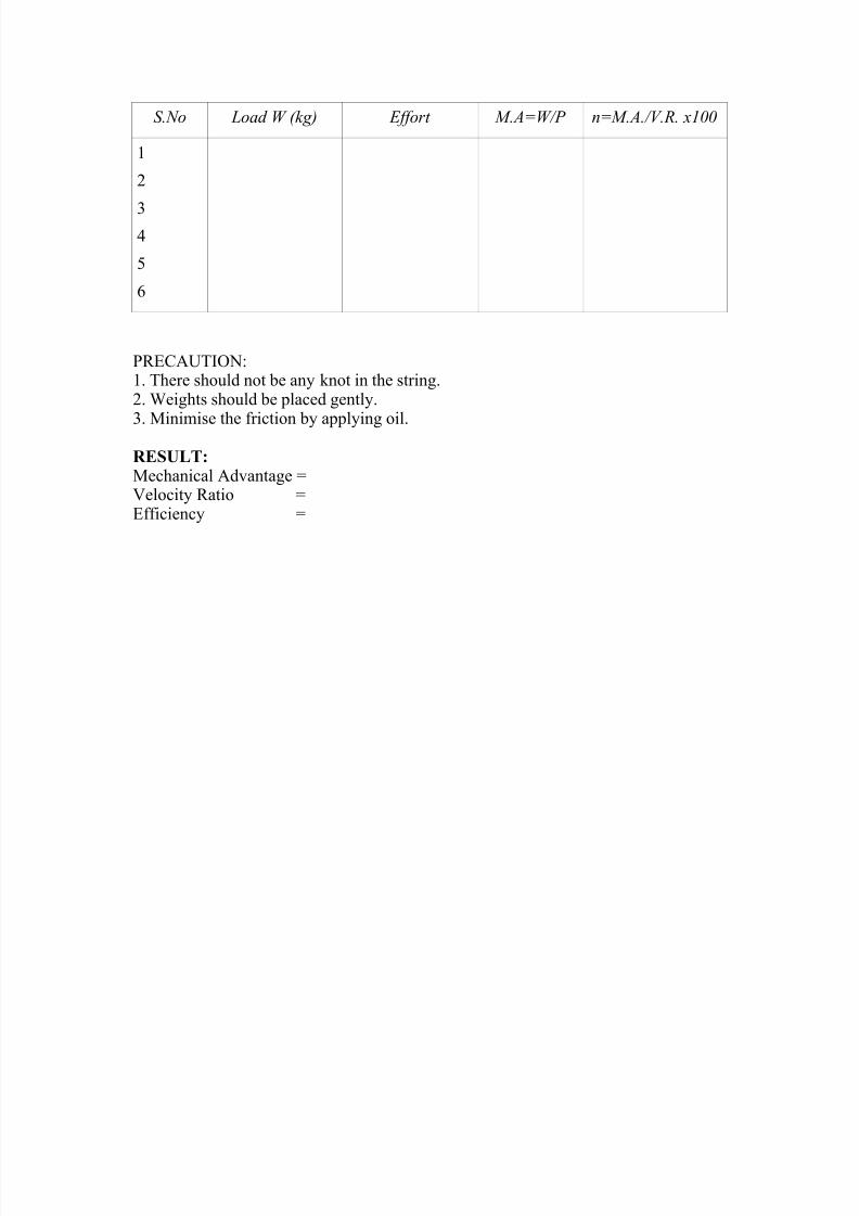
S.No Load W (kg) Effort M.A=W/P "=M.A./V.R. x100
1
2
34
P57;<T$6N:1. T!ere s!ould not be an( >not in t!e string.2. Deig!ts s!ould be placed gentl(.
3. inimise t!e friction b( appl(ing oil.RESULT:ec!anical dvantage )8elocit( 5atio )7fficienc( )
8/13/2019 Som Manuals 2005
http://slidepdf.com/reader/full/som-manuals-2005 20/22
Haryana EngineeringCollege
-oc.: H7;*7;H*7/217*+/3*P/10
Exp!"#$% I$&%!'%"$& $ssue: 01
Page No.: 1 of 2
AIM- To determine t!e modulus of rigidit( of t!e material of a close coiled !elical springand t!e stiffness of a spring.
REQUIREMENT:-;ombined compression and e%pansion of springs apparatus close coiled springs 3"steel rule" vernier clippers" load !anger and #eig!ts.
THEORY:-Kust li>e direct stress and strain" t!e s!ear strains are also proportional to s!ear stressup to a certain limiting value and is e%pressed b( t!e e&uation+!ear stress*s!ear strain ) constantT!is constant for a material is denoted b( F and is called t!e modulus of rigidit( of aclose coiled !elical springS t!e deflection is given b( δR δR ) GD-3n*Fd4
-0 ) 6uter diameter of spring- ) ean coil diameter d ) -iameter of #ire
n ) number of free coilsF ) GD-3n*d4δR
+lope of D 8s δR grap! can be calculated and dra#n.+tiffness of a spring or spring constant is t!e load per unit deflection ) D*δR for aspring +lope of D*δR grap! outer diameter of coil -o
PROCEDURE:1. T!e #ire diameter" mean coil diameter and no. of free coils are measured.2. +et up spring in t!e tension space of t!e apparatus and appl( a suitable initial load
to open t!e coil and @ero t!e vernier scale. ppl( increasing loads to t!e spring insuitable increments and in eac! case record t!e corresponding deflectionsindicated b( t!e vernier scale.
3. Plot a grap! of load P v*s deflection based on reading ta>en. <sing t!e slope oft!is grap! in conAunction #it! t!e particular spring dia. determine t!e modulus ofrigidit( of t!e material of t!e spring.
8/13/2019 Som Manuals 2005
http://slidepdf.com/reader/full/som-manuals-2005 21/22
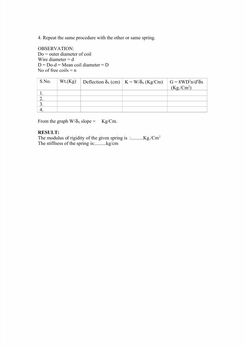
4. 5epeat t!e same procedure #it! t!e ot!er or same spring.
6B+758T$6N:-o ) outer diameter of coil
Dire diameter ) d- ) -o/d ) ean coil diameter ) - No of free coils ) n
+.No. Dt.Eg -eflection δR cm E ) D*δR Eg*;m F ) GD-3n*d4δ%Eg.*;m2
1.2.3.4.
'rom t!e grap! D*δR slope ) Eg*;m.
RESULT:T!e modulus of rigidit( of t!e given spring is :..........Eg.*;m2
T!e stiffness of t!e spring is:.........>g*cm

8/13/2019 Som Manuals 2005
http://slidepdf.com/reader/full/som-manuals-2005 22/22