Embed Size (px)
Citation preview
1
SOLVING THE CONFLICT BETWEEN BASEMENT
WATERPROOFING BEST PRACTICE AND RADON MANAGEMENT
IN THE UNITED KINGDOM
Martin Freeman (1)
Chair of UK Radon Association
[email protected] / [email protected]
Abstract
Cellar conversion and new basement creation is widespread in the UK where basement living
and working is frequent. All basements are at risk of elevated radon levels regardless of
geographic location. In 1999, a landmark court ruling altered the approach to waterproofing,
steering designers and contractors towards the use of internally fitted drained cavity drain
membrane systems. Based on air-gap technology, these membrane systems are not
appropriate for gas proofing; in part of continental Europe their use is specifically
discouraged for that purpose. The author set about resolving the conflict between good
waterproofing practice and radon gas management in basements, producing a successful
solution.
The paper explores the background of UK basement use, the key points of the landmark
judgment and subsequent code of practice for below ground waterproofing. This code of
practice now requires radon to be considered in waterproofing design and implementation,
but overlooks how this might be achieved. The paper describes the process that was
developed to solve the dilemma and illustrates with case studies.
Although construction practices and basement usage differ across the globe, the principles
involved may have relevant applications internationally.
Introduction
In this paper, a basement is defined as being “a usable part of a building that is situated partly
or entirely below ground level” and a cellar is defined as a “basement used for storage,
heating plant and for purposes other than habitation”.1
Where radon (radon-222) measurements are referred to, they are given in Becquerels per
cubic metre of air (Bq/m3) with approximate conversions into Picocuries per litre of air
(pCi/L) shown beside. Measurements referred to in this paper were obtained using passive
detectors and track etch technology. Passive detectors were supplied and analysis undertaken
by Track Analysis Systems Limited, a UK laboratory validated by Public Health England.
Basement living and working are frequent in the UK. Basement and ‘Garden’ flats are a
regular feature of most towns and cities; similarly basement offices are plentiful, office
(1)
The author is the inventor of the process described in this paper and is a director and shareholder of a
company that, among other things, installs this process
2
blocks usually have basements and a significant number of town centre stores and restaurants
utilise basements.
Property (and land) is expensive in the UK and particularly in cities basement creation or
cellar conversion is routinely undertaken to maximise accommodation. For similar reasons,
many new builds include basements to get the most out of site development.
Radon in Basements in the UK
Radon is responsible for some 2000 lung cancer deaths in the UK each year.2
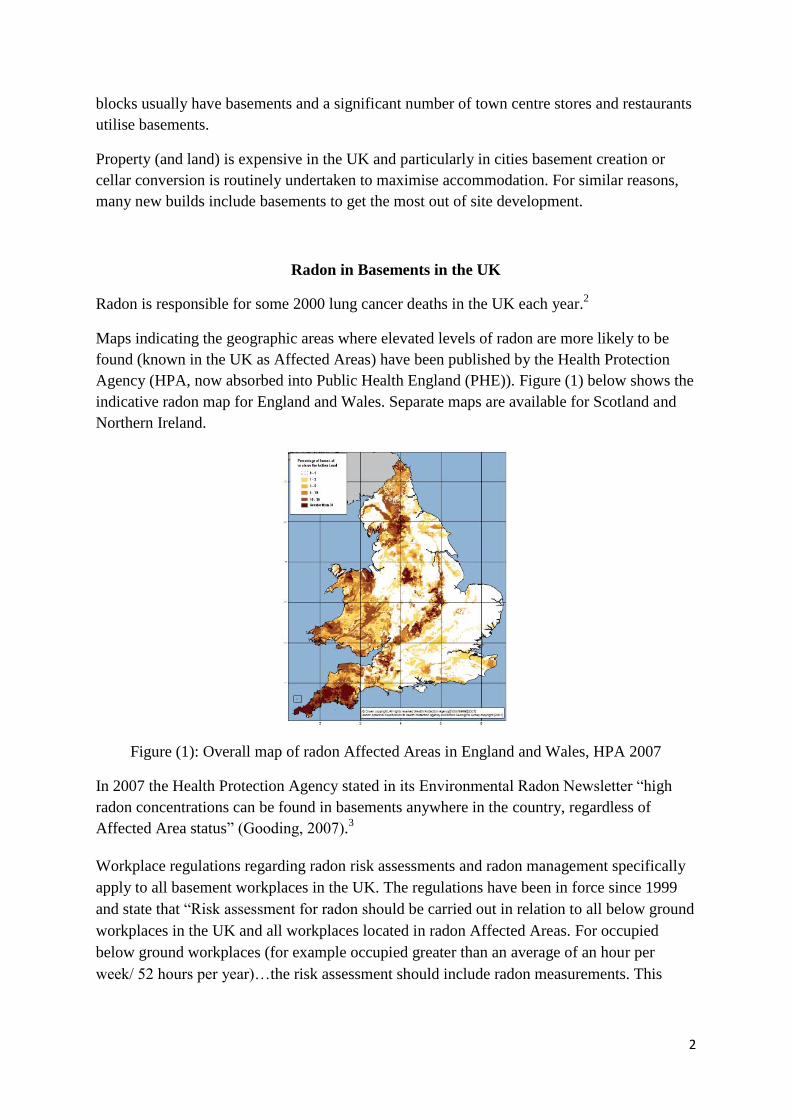
Maps indicating the geographic areas where elevated levels of radon are more likely to be
found (known in the UK as Affected Areas) have been published by the Health Protection
Agency (HPA, now absorbed into Public Health England (PHE)). Figure (1) below shows the
indicative radon map for England and Wales. Separate maps are available for Scotland and
Northern Ireland.
Figure (1): Overall map of radon Affected Areas in England and Wales, HPA 2007
In 2007 the Health Protection Agency stated in its Environmental Radon Newsletter “high
radon concentrations can be found in basements anywhere in the country, regardless of
Affected Area status” (Gooding, 2007).3
Workplace regulations regarding radon risk assessments and radon management specifically
apply to all basement workplaces in the UK. The regulations have been in force since 1999
and state that “Risk assessment for radon should be carried out in relation to all below ground
workplaces in the UK and all workplaces located in radon Affected Areas. For occupied
below ground workplaces (for example occupied greater than an average of an hour per
week/ 52 hours per year)…the risk assessment should include radon measurements. This
3
applies to all below ground workplaces in the UK, irrespective of the above ground Affected
Areas status.” 4
Thus it can be seen that basements have long been recognised as areas at risk of elevated
radon levels. This is hardly surprising since radon is a soil gas and a basement may have up
to five surfaces in communication with the soil, as opposed to a single surface for a building
constructed on the ground.
Radon sump systems (known as sub-slab depressurisation systems or SSDs in the USA) are
recognised as an effective method of radon management by providing a void with low
pressure under the building where radon can be collected and subsequently managed away
from the building.5
A basement is, in effect, a large sump (or SSD) that people live or work in.
History of UK Waterproofing.
Until the 1990s waterproofing was undertaken by the damp proofing industry, many of whom
did not understand the distinction between ‘damp proofing’ (action against capillary-held
moisture) and ‘waterproofing’ (action against intrusion of free water) or by general building
contractors. Techniques involved bitumen emulsions, mastic asphalt, or dense cement based
render systems. New build basements were increasingly provided with externally fixed self-
adhesive sheet membranes typically made from rubber/bitumen and polyethylene.
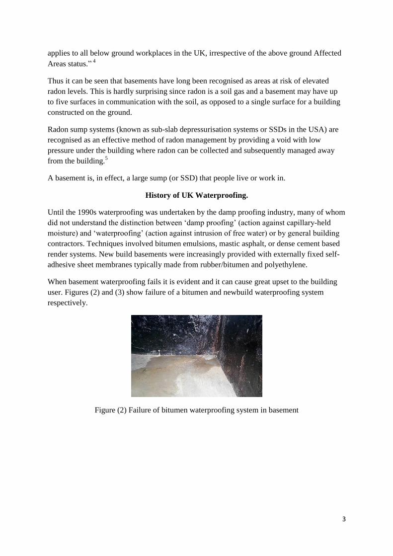
When basement waterproofing fails it is evident and it can cause great upset to the building
user. Figures (2) and (3) show failure of a bitumen and newbuild waterproofing system
respectively.
Figure (2) Failure of bitumen waterproofing system in basement
4
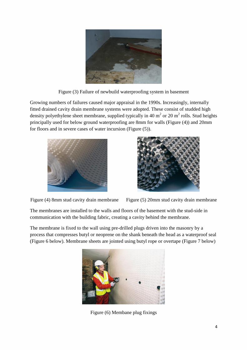
Figure (3) Failure of newbuild waterproofing system in basement
Growing numbers of failures caused major appraisal in the 1990s. Increasingly, internally
fitted drained cavity drain membrane systems were adopted. These consist of studded high
density polyethylene sheet membrane, supplied typically in 40 m2 or 20 m
2 rolls. Stud heights
principally used for below ground waterproofing are 8mm for walls (Figure (4)) and 20mm
for floors and in severe cases of water incursion (Figure (5)).
Figure (4) 8mm stud cavity drain membrane Figure (5) 20mm stud cavity drain membrane
The membranes are installed to the walls and floors of the basement with the stud-side in
communication with the building fabric, creating a cavity behind the membrane.
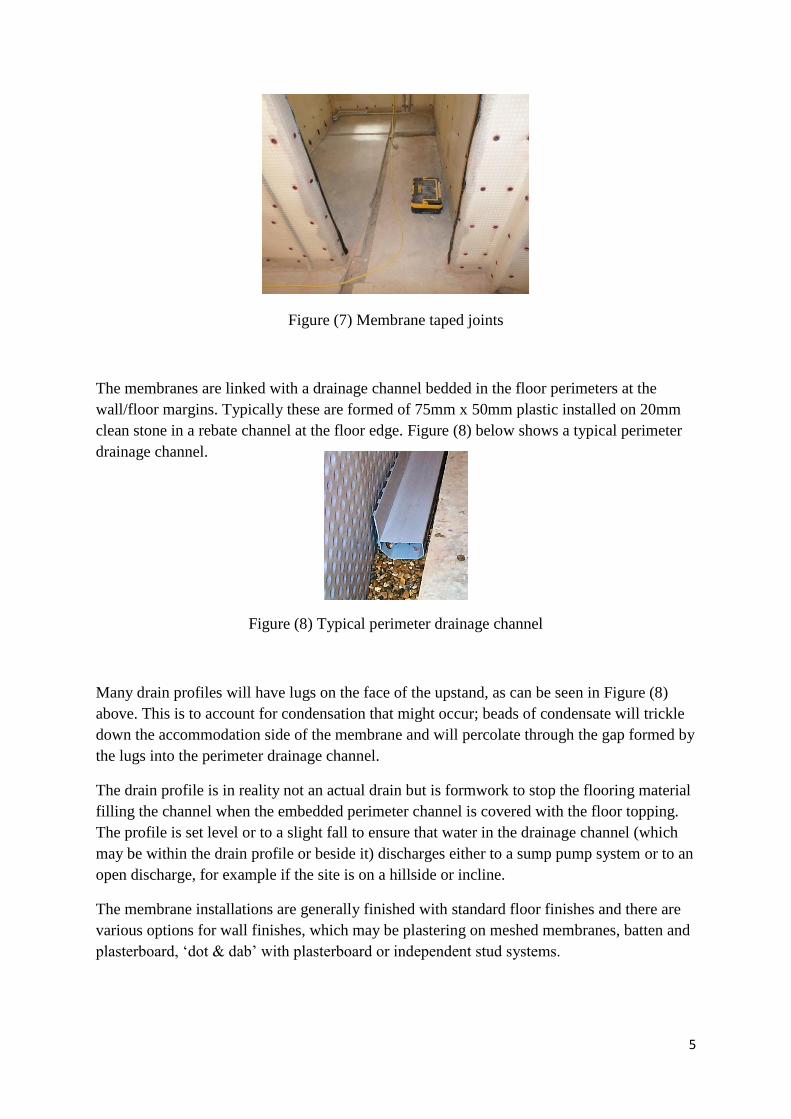
The membrane is fixed to the wall using pre-drilled plugs driven into the masonry by a
process that compresses butyl or neoprene on the shank beneath the head as a waterproof seal
(Figure 6 below). Membrane sheets are jointed using butyl rope or overtape (Figure 7 below)
Figure (6) Membane plug fixings
5
Figure (7) Membrane taped joints
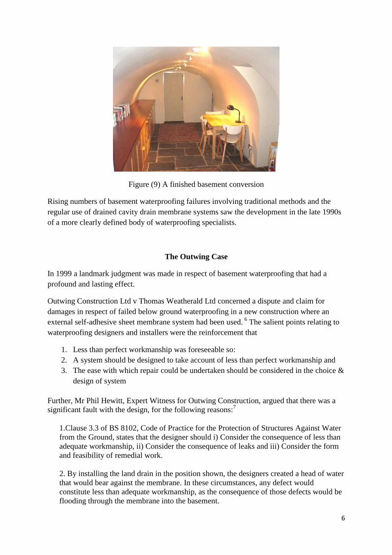
The membranes are linked with a drainage channel bedded in the floor perimeters at the
wall/floor margins. Typically these are formed of 75mm x 50mm plastic installed on 20mm
clean stone in a rebate channel at the floor edge. Figure (8) below shows a typical perimeter
drainage channel.
Figure (8) Typical perimeter drainage channel
Many drain profiles will have lugs on the face of the upstand, as can be seen in Figure (8)
above. This is to account for condensation that might occur; beads of condensate will trickle
down the accommodation side of the membrane and will percolate through the gap formed by
the lugs into the perimeter drainage channel.
The drain profile is in reality not an actual drain but is formwork to stop the flooring material
filling the channel when the embedded perimeter channel is covered with the floor topping.
The profile is set level or to a slight fall to ensure that water in the drainage channel (which
may be within the drain profile or beside it) discharges either to a sump pump system or to an
open discharge, for example if the site is on a hillside or incline.
The membrane installations are generally finished with standard floor finishes and there are
various options for wall finishes, which may be plastering on meshed membranes, batten and
plasterboard, ‘dot & dab’ with plasterboard or independent stud systems.
6
Figure (9) A finished basement conversion
Rising numbers of basement waterproofing failures involving traditional methods and the
regular use of drained cavity drain membrane systems saw the development in the late 1990s
of a more clearly defined body of waterproofing specialists.
The Outwing Case
In 1999 a landmark judgment was made in respect of basement waterproofing that had a
profound and lasting effect.
Outwing Construction Ltd v Thomas Weatherald Ltd concerned a dispute and claim for
damages in respect of failed below ground waterproofing in a new construction where an
external self-adhesive sheet membrane system had been used. 6
The salient points relating to
waterproofing designers and installers were the reinforcement that
1. Less than perfect workmanship was foreseeable so:
2. A system should be designed to take account of less than perfect workmanship and
3. The ease with which repair could be undertaken should be considered in the choice &
design of system
Further, Mr Phil Hewitt, Expert Witness for Outwing Construction, argued that there was a
significant fault with the design, for the following reasons:7
1.Clause 3.3 of BS 8102, Code of Practice for the Protection of Structures Against Water
from the Ground, states that the designer should i) Consider the consequence of less than
adequate workmanship, ii) Consider the consequence of leaks and iii) Consider the form
and feasibility of remedial work.
2. By installing the land drain in the position shown, the designers created a head of water
that would bear against the membrane. In these circumstances, any defect would
constitute less than adequate workmanship, as the consequence of those defects would be
flooding through the membrane into the basement.
7
3. It is not realistic or reasonable to expect a bonded sheet membrane to be applied
without any defects at all.
4. Clause 3.1.1 of BS 8102, Pre-Design Considerations, recommends that basements
should include provision for resisting a pressure equivalent of 1m head of water at least.
5. The interpretation of the above was that a design team must anticipate that defects will
occur in a membrane, and so must design a system in such a way that water pressure is
removed before it comes to bear against the membrane. If they are unable to achieve this,
it is implied that an alternative form of waterproofing must be used.
6. Furthermore, a bonded sheet membrane is only one element within an overall
waterproofing system. The membrane, together with the drainage and the structure, all
form part of the system and must be considered together. No one element should be
considered in isolation.
In his judgment, Recorder Colin Reese QC agreed with this evidence without reservation.
The rulings in this landmark case set legal precedents.
After the Outwing case, there was a major swing towards the use of drained cavity drain
membrane systems as primary waterproofing systems and as secondary systems to
integral waterproofing and sheet membrane installations.
This shift and the key points of the Outwing case Judgment were recognised and formally
embodied in a revision of the relevant Code of Practice, BS8102:2009 Code of practice
for protection of below ground structures from water from the ground.8
2009 Revision of BS8102 Code of Practice
The Code of Practice not only led waterproofers towards drained cavity drain membrane
systems (referred to in the Code as Type C systems) but – crucially – for the first time
recognised a duty by designers and installers to take account of radon
8
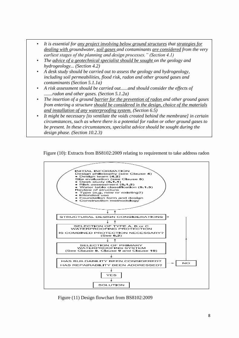
Figure (10): Extracts from BS8102:2009 relating to requirement to take address radon
Figure (11) Design flowchart from BS8102:2009
• It is essential for any project involving below ground structures that strategies for
dealing with groundwater, soil gases and contaminants are considered from the very
earliest stages of the planning and design processes.” (Section 4.1)
• The advice of a geotechnical specialist should be sought on the geology and
hydrogeology... (Section 4.2)
• A desk study should be carried out to assess the geology and hydrogeology,
including soil permeabilities, flood risk, radon and other ground gases and
contaminants (Section 5.1.1a)
• A risk assessment should be carried out......and should consider the effects of
.......radon and other gases. (Section 5.1.2a)
• The insertion of a ground barrier for the prevention of radon and other ground gases
from entering a structure should be considered in the design, choice of the materials
and installation of any waterproofing system. (Section 6.5)
• It might be necessary [to ventilate the voids created behind the membrane] in certain
circumstances, such as where there is a potential for radon or other ground gases to
be present. In these circumstances, specialist advice should be sought during the
design phase. (Section 10.2.3)
9
At this time, the waterproofing industry was made aware of an important published statement
from Professor William Angell, Chair of the World Health Organisation Radon Project
Prevention and Mitigation Group:
“WHO Radon Handbook emphasizes that indoors, radon is largely caused by the way
homes are designed and built, and clarifies the long-term misconception that indoor
radon is naturally occurring. Outdoor radon concentrations are naturally occurring but
indoors, radon concentrations are profoundly influenced by the way homes are
designed and built. The implications of this clarification are that it places clear
responsibility for radon control on:
• Architects and designers
• Builders
• Building Code Officials
• Real Estate Agents etc” (Angell, 2009)9
The Conflict Between Type C Waterproofing and Radon Management
By 2009, drained cavity drain membrane systems had become recognised as the ‘best
practice’ form of waterproofing and the first choice of designers and installers. For good
radon management this presented a problem. The very nature of the dimpled membranes
is based upon what manufacturers describe as ‘air gap technology’. An air gap is created
between the raised studs or dimples on the rear side of the membrane so that water can
depressurise after passage through the wall and is guided by the membrane to fall to the
drainage channel at the base. Typically an 8mm stud height membrane will have an air
space of 4 litres/m2 and a 20mm stud will have an air space of 14 litres/m
2.10 (Volumes
will vary slightly between manufacturers and membrane types according to stud diameter,
shape and density).
Type C waterproofing lines the walls, floors and, in vaulted situations ceilings, to form in
effect a ‘room within a room’ which has a cavity between the lining and the soil that
provides a pathway for radon. Within the basement, indoor pressure can be expected to be
lower than soil air pressure and outside air pressure (McHugh et al, 2006).11
Cavity drain
membrane systems are water management systems. They are not designed to behave as
perfect waterproof membrane/barriers. They are favoured positively because they do not
require perfection. The basement when put into use will generate a significant ‘stack
effect’ (Crump et al, 2005)12
.
In consequence, basements waterproofed with a drained cavity drain membrane system
are effectively large radon collection sumps which serve at worst as living or work
spaces, or at least as collection points from which radon can be despatched into
accommodation above the basement.
Cavity drain membranes are not intended to be airtight and it would be difficult to make
them so due to their weight relative to the size and population density of fixings, thermal
movement in the membrane sheets as well as movements in the various substrates. These
factors can cause installations to ‘relax’ over time. Such relaxation will not normally have
any adverse effect on the waterproofing performance but render it impractical to convert
these systems into gas barriers. In parts of Europe their use for this purpose is
10
discouraged. For example, “According to the Czech technical standard ČSN 73 0601 it is
not allowed to use plastic membranes with dimples for radon barriers, because it is nearly
impossible to provide airtight joints between membranes” (Jiranek, 2006).13
The Solution
The conflict between good waterproofing and poor radon management was resolved by
addressing and managing the pressure relationships.
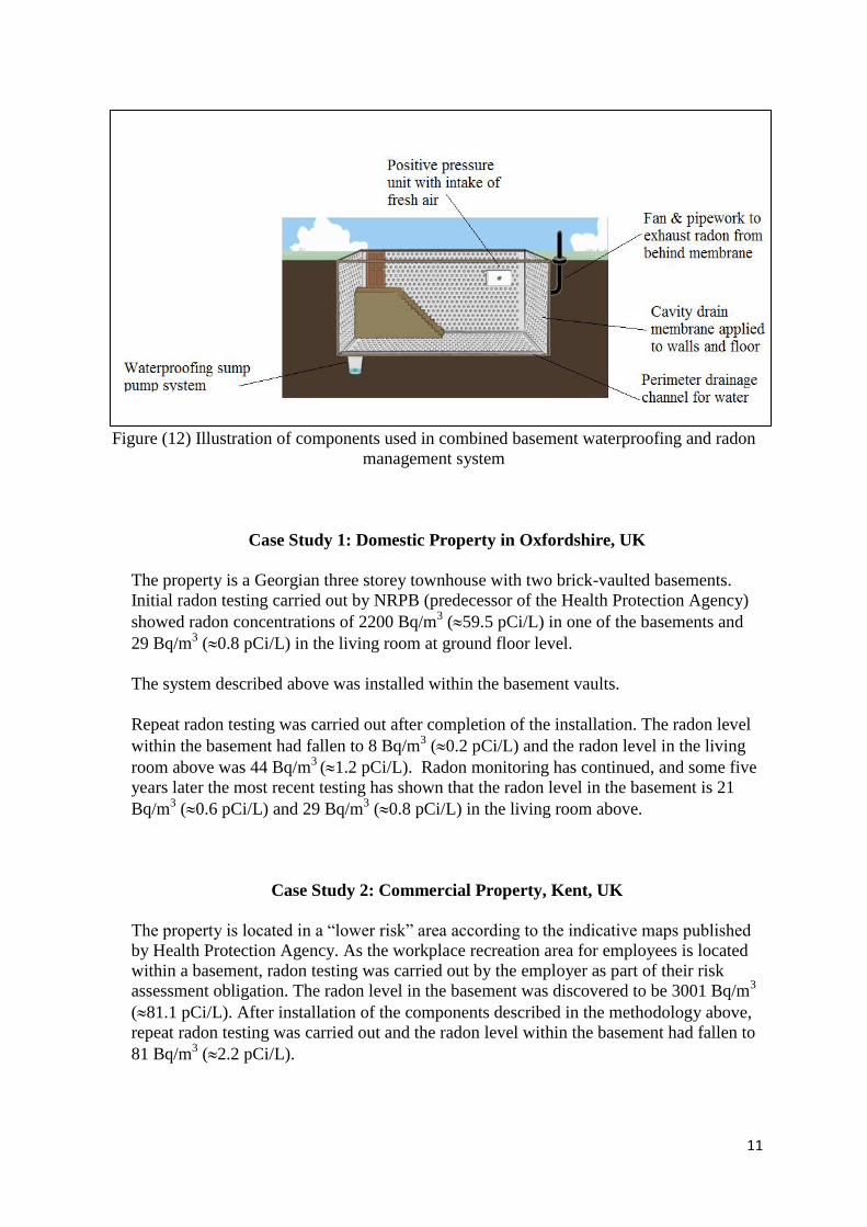
A standard Type C system is installed but with an attempt to seal joints as far as possible
including sealing the condensate trickle gap on the drain profile upstand. These actions
will reduce the demand on subsequent positive air pressure that is introduced and which
will also have the incidental benefit of mitigating condensation. Sealing the head of
membranes that are wall mounted with a flat soffit at the top will avoid radon from
behind the membrane being displaced to the accommodation above.
A positive pressure unit is installed within the accommodation with ducting drawing air
from outside the building. The positive pressure unit should incorporate a heater facility
to pre-warm the air to an ambient indoor level during the colder months. The purpose of
the positive pressure unit is to create a higher pressure within the accommodation relative
to the pressure behind the membrane and in the surrounding soil. This means that even if
there are imperfections in the membrane, advection of radon should not occur into the
habitable accommodation.
The area behind the membrane acts as a radon collection sump. At the time of installation
of the system, provision should be made for the installation of an inline exhaust fan to
draw radon from this area and evacuate it outside the building. Pipework leading from the
air gap behind the membrane should be taken to a convenient location outside the
building and capped off. Its purpose should be clearly labelled.
After the basement has been completed, radon testing should be carried out, both within
the basement and the ground floor accommodation to ascertain whether an inline fan
should be added to ‘activate’ the exhaust system. Where the air gap behind the membrane
is not continuous, additional exhaust points will be required.
11
Figure (12) Illustration of components used in combined basement waterproofing and radon
management system
Case Study 1: Domestic Property in Oxfordshire, UK
The property is a Georgian three storey townhouse with two brick-vaulted basements.
Initial radon testing carried out by NRPB (predecessor of the Health Protection Agency)
showed radon concentrations of 2200 Bq/m3 (59.5 pCi/L) in one of the basements and
29 Bq/m3 (0.8 pCi/L) in the living room at ground floor level.
The system described above was installed within the basement vaults.
Repeat radon testing was carried out after completion of the installation. The radon level
within the basement had fallen to 8 Bq/m3 (0.2 pCi/L) and the radon level in the living
room above was 44 Bq/m3
(1.2 pCi/L). Radon monitoring has continued, and some five
years later the most recent testing has shown that the radon level in the basement is 21
Bq/m3 (0.6 pCi/L) and 29 Bq/m
3 (0.8 pCi/L) in the living room above.
Case Study 2: Commercial Property, Kent, UK
The property is located in a “lower risk” area according to the indicative maps published
by Health Protection Agency. As the workplace recreation area for employees is located
within a basement, radon testing was carried out by the employer as part of their risk
assessment obligation. The radon level in the basement was discovered to be 3001 Bq/m3
(81.1 pCi/L). After installation of the components described in the methodology above,
repeat radon testing was carried out and the radon level within the basement had fallen to
81 Bq/m3 (2.2 pCi/L).
12
Case Study 3: Domestic Property, Somerset, UK
The property is a three storey Edwardian villa with a basement beneath part of the ground
floor footprint. Upon purchasing the property, the owners carried out a radon test which
revealed radon levels of 412 Bq/m3 (11.1 pCi/L) within the basement. After installation
of the components described in the methodology above, repeat radon testing was carried
out and the radon level within the basement had fallen to 104 Bq/m3
(2.8 pCi/L).
Conclusions
Basement usage in the UK is common as living and work space. Basements are
susceptible to the accumulation of elevated levels of radon which presents a serious
health risk. The Code of Practice for basement waterproofing requires designers and
installers to take account of radon. Those who fail to do so may find themselves adjudged
at fault and responsible for any consequences.
The process of combined waterproofing and radon gas management described in this
paper has been shown to be effective and takes account of the crucial principles in that
perfect workmanship in membrane installation is not essential and that all elements of the
process can be accessed for repair and maintenance.
Best practice waterproofing in the UK can be successfully combined with effective radon
management. There are more than 300 specialist waterproofing contractors in the UK,
few of whom have knowledge of or competence in radon management or who offer radon
management as part of their waterproofing. The recently formed UK Radon Association
has created a category of membership together with suitable training to overcome this
important gap in knowledge and skill.
13
References
1 BS 6100-0:2010 Building and civil engineering. Vocabulary, British Standards Institute
2 http://www.hse.gov.uk/radiation/ionising/radon.htm
3 Gooding, 2007, Issue 53 Environmental Radon Newsletter, Health Protection Agency
4 http://www.hse.gov.uk/radiation/ionising/radon.htm
5 Scivyer, 2013, Radon solutions in homes: Part 3 Radon sump systems, BRE
6 Outwing Construction Limited v Thomas Weatherald Limited. No 1998 0 011. High Court
of Justice Queen’s Bench Division Technology and Construction Court, 13 September 1999,
1999 WL 1048254
7 http://home.btconnect.com/philhewitt/Outwing.htm
8 BS8102:2009 Code of practice for protection of below ground structures from water from
the ground, 2009, BSI
9 Angell, 2009, Highlights of World Health Organization’s WHO Handbook in Indoor
Radon: A Public Health Perspective
10 www.wykamol.com
11 McHugh et al, 2006, Indoor Air as a Source of VOC Contamination in Shallow Soils
Below Buildings, Soil & Sediment Contamination, 15:103-122
12 Crump et al, 2005, Review of Building Parameters for Development of a Soil Vapour
Intrusion Model, Environment Agency
13 Jiranek, 2006, Consequences of Incorrect Design and Unqualified Realization on
Reliability and Effectiveness of Radon Reduction Measures, In: Radon investigations in the
Czech Republic and the 8th international workshop on the Geological Aspects of Radon Risk
Mapping. 2006 Sep 26–30; Praha, Czech Republic. p. 123–130