Embed Size (px)
Citation preview
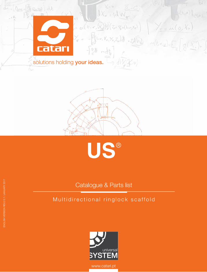
Catalogue & Parts list
solutions holding your ideas.
M u l t i d i r e c t i o n a l r i n g l o c k s c a f f o l d
ENG
LISH
VER
SIO
N RE
V.2
E.1
/ JAN
UARY
201
7
US®

solutions holding your ideas.

CONTENT
Catari Universal System® (US® ) is a modular system consisting, in terms of structure, of vertical and horizontal elements and diagonal braces, combined to form a tubular steel truss.

4
Catari US® is manufactured using high-strength steel, with an automated welding and coated with a hot dip galvanization, which offers to the user the highest product quality and durability with the least possible maintenance.
Its design is based on the ringlock fitting - rosette - and it is meant for the most complex and demanding scaffold constructions.
The rosette is an eight holes disk welded to the standards every fifty centimeters, that can accommodate up to eight connections of combined ledgers or diagonal braces through a wedge locking mechanism.
HIGH PERFORMANCE SCAFFOLD
SAFETY
With a simple hammer blow, unblocked connections are transformed into blocked ones (wedge locking mechanism).
Moreover, once the end of the wedge head matches the radius of the standard, forces are transmitted centrally onto the standard over a wide area, assuring solid and high load-bearing capacity joints.
VERSATILITY
The geometry of the rosette, with two sizes of holes, allows a wide-ranging combination of angles between ledgers.
This, along with the range of accessories available and the high load-bearing capacity of joints, grants a wide array of layouts and an unmatched range of uses: simple façades, complex industrial structures, sophisticated supporting structures, access or working towers.
Variable spacing for the standards and ledgers ensure that the design of the scaffold comply optimally with on-site conditions.
SPEED AND EASE OF ASSEMBLY
The rigid fitting and the wedge blocking mechanism, fast and non-bolted, ensure automatically right-angled connections, linear or angled, and waiver special assembly tools.
The assembly of the system is self-explanatory and can be complied in safety by regular scaffold crews.
COST-EFFECTIVENESS
Once the ringlock fitting uses a blocking wedge, in replace of the time consuming screwed connections of conventional scaffold, the assembly process is simple and reduces, thereby, the manpower needs.
In addition, as with the same components numerous applications are possible, on-site material requirements are automatically reduced and utilization rates are increased.

5
INDEX
04 SYSTEM OVERVIEW
Catari US® presentation, safety, versatility, speed and ease of assembly, cost-effectiveness.
06 HOW IT WORKS
Brief description of Catari US® assembly steps.
07 YOUR BENEFIT
Numbers and facts regarding Catari US®.
08 WHAT YOU CAN DO
Advantages and presentation of the most demanded range of uses.
15 CERTIFICATION
Catari and US® certification and quality control.
16 PARTS LIST
Base jacks, collars and castorsStandardsLedgersBridging ledgersDiagonal bracesSteel decks and access decksToe boardsStaircasesGuardrailsShoring headsCouplers and accessories

6
Catari US® is a modular system designed to be intuitive and fast to assemble.It consists of vertical, horizontal and diagonal steel parts, that when combined form a strong and robust scaffold.Its main feature is the ringlock fitting, that transforms its assembly into an easy and simple task.At this moment you are 8 steps away to discover how it can be simple:
HOW DOES IT WORK?
Project the structureYou can contact Catari to request a 3D project.
Choose the componentsOr ask for our opinion and guidance to obtain the best price and solution.
Place the bases & collars And connect them with ledgers using the ring- lock fitting. Level all the structure.
Place the standardsOnto the collars.
You have 8 connection possibilitiesWith the help of a regular hammer simply connect (longitudinally and horizontally) every standard to the other using ledgers and diagonals.
Place the platforms & stairsIf or when needed.
Anchor the structureAs stated in your project.
Simply repeat steps 4, 5, 6 & 7Until you finish the structure and don’t forget to usethe pigtails or screws to lock every level.

7
13+4035kN
50%PROFIT
Catari US® numbers and facts.
Types of assembly offered by one system.
Is the number of couplers spared with only one standard.
Working load per standard.
Guaranteed time saving.
24 to 48 months payback in rental business.Considerable years of lifetime durability.
WHAT IS YOUR BENEFIT?

8
WHAT CAN YOU DO?
Catari US® allows you to assemble different types of structures with the same basic components. The following are assembly examples for the most demanded range of uses.
FAÇADEBricklaying, plastering, coatingComprehensive range of assembly options is provided for optimum adaptation to irregular façades, such as cornices, cantilevers and niches.
Advantages:
0 nails required to assemble an entire façade.
2000 m2 of façade scaffold can be transported in one truck.
8h is the average time for 3 workers to assemble 300 m2.
INDUSTRIALComplex and demanding structures The range of accessories grant high levels of safety and flexibility which are mandatory for all kind of industries.
Advantages:
MULTIPLE ANGLES you can achieve, adapting to circular or irregular surfaces you will be working on.
3 types of access you can use: access decks, staircases or simple ladder.
7 horizontal standard sizes plus custom made parts to fit your every need.

9
SHORINGFalsework and proppingEnsure temporary support for spanning or arched structures in order to hold the components in place until they can support themselves.
Advantages:
35 kN working load per crosshead jack.
3000 m3 of shoring scaffold can be transported in one truck.
3000 kg you can achieve per m2.
SUSPENDED SCAFFOLDReach voids, hollows and wellsEnsure on-site safety within workplaces reachable only from overhead or lateral structures.
Advantages:
8 m of span you can go up to.
2,44 kN/m2 you can go up to.
10
REBARAnchorless access to wallsStability is achieved through simple support and, if required, by widening the base.
Advantages:
1 crane will enable fast displacement of the assembly.
12 m is the height you can achieve free-standing.
WORKING TOWERSFaçade or ceiling works, within tight contexts Lightweight aluminium decks, with trap mechanism and integrated ladders, grant quick assembling and ease of movement between levels.
Advantages:
ALL LEVELS can endure workers simultaneously.
2 workers can work per each m2.
750 kg per castor you can move on a mobile working tower.
11
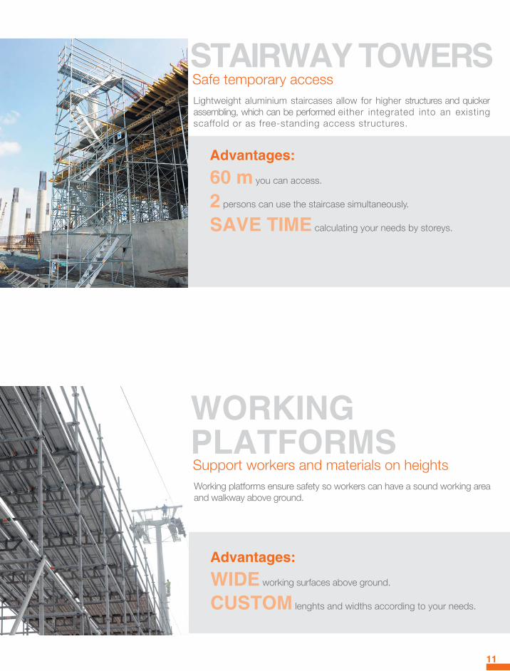
STAIRWAY TOWERSSafe temporary accessLightweight aluminium staircases allow for higher structures and quicker assembling, which can be performed either integrated into an existing scaffold or as free-standing access structures.
Advantages:
60 m you can access.
2 persons can use the staircase simultaneously.
SAVE TIME calculating your needs by storeys.
WORKING PLATFORMSSupport workers and materials on heightsWorking platforms ensure safety so workers can have a sound working area and walkway above ground.
Advantages:
WIDE working surfaces above ground.
CUSTOM lenghts and widths according to your needs.

12
ADVERTISEMENTSupporting structuresRe-create the classic outdoor through the US® versatility, allowing a multi-purpose ad solution and interaction with bystanders.
Advantages:
X*Y m don’t be limited by usual outdoor sizes.
€ increase your façade’s value.
EVENTSCultural, artistic, sportive and music festivalsWith the standard components it is possible to assemble structures or part of structures. Benches, stages or even screens are some of the most commonly assembled structures.
Advantages:
PLAN a whole event with only one system.
ORIGINAL stages adapted to demanding and complex contexts.
500.000 persons attended events in 2015 with US®.
13
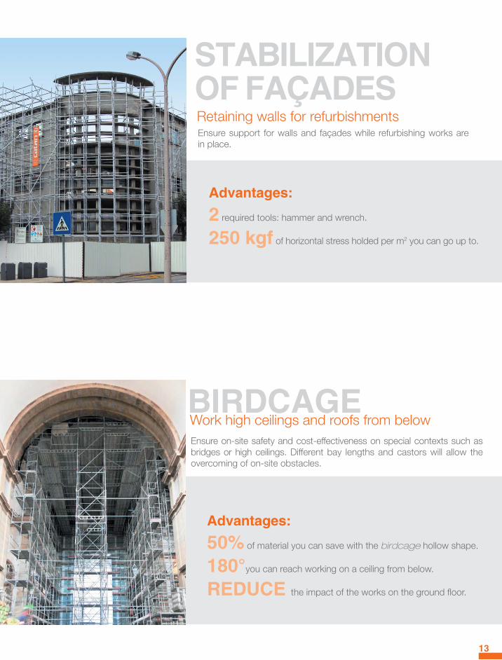
STABILIZATION OF FAÇADESRetaining walls for refurbishmentsEnsure support for walls and façades while refurbishing works are in place.
Advantages:
2 required tools: hammer and wrench.
250 kgf of horizontal stress holded per m2 you can go up to.
BIRDCAGEWork high ceilings and roofs from belowEnsure on-site safety and cost-effectiveness on special contexts such as bridges or high ceilings. Different bay lengths and castors will allow the overcoming of on-site obstacles.
Advantages:
50% of material you can save with the birdcage hollow shape.
180°you can reach working on a ceiling from below.
REDUCE the impact of the works on the ground floor.

14
FLYOVERSCrossing over gapsWith standard parts and steel decks it is possible to easily assemble connections over excavations or rivers.
Advantages:
12 m span you can reach.
CLASS 6 certified Steel Decks up to 207 cm long.
OVERCOME spans even on high slopes.
OTHER APPLICATIONSUnusual scaffold assembliesLess frequently seen assemblies of scaffold can also be projected on demand.
Examples:
Slung scaffold.Pipe rack.Mobile scaffold.Custom engineering projects.
The assembled structures graphics displayed are for information only and may show the situation during scaffold assembly, therefore not always are complete from the safety point of view. The graphics give general overview and cannot cover all the possible applications. All dimension and weight related data is only approximate and appropriate static calculations and structure’s project should be performed to prove the appropriate configuration of US® components for each assembly situation. When assembing and disassembling US® the contractor is entitled to decide in which way the safety and hazzard must be ensured in an adequate manner under the observance of the respective industrial safety regulations. Possible protective actions are technical measures, personal protective equipment (PPE), and special instructions. Please request Catari the specific instructions for assembly and use when ordering.

15
CATARI ISO 9001:2008 WITH QUALITY CONTROL PROCESSES OF HIGH TECHNICAL STANDARDS.
Besides the processes and product certification, carried out by internationally recognized and respected institutions, Catari has internal procedures that reinforce quality control and non conformity prevention.
Continuous efforts across departments to improve products, services and procedures are our daily commitment.
US® EN-12810MODULAR SCAFFOLD SYSTEM UNDER THE EUROPEAN STANDARDS.
The European Norm 12810-1 has been adopted by the European Committee for Normalization (CEN) on September 2003.
This document, which replaces the previous HD 1000 of 1998, in direct application to the signing states, specifies the performance and general requirements for structural design and evaluation of prefabricated scaffold systems.
CERTIFICATION

180°
16
BASE JACK
Ensures the correct transmission of loads to the ground. The spindle allows the correct height adjustment.
.Ref. .Spindle height (cm) .Weight (kg)
AA.BN.500 50 (Max. spindle: 30) 3,10AA.BN.700 70 (Max. spindle: 50) 3,70
SWIVEL BASE JACK
Ensures the correct transmission of loads to the ground on surfaces with slope.
.Ref. .Spindle height (cm) .Weight (kg)
AA.BNA.650 65 (Max. spindle: 45) 4,20
SCAFFOLD CASTOR
With twin break (simultaneous lock) and poly-amide wheel.Allows to displace the scaffold bidirectionally.
.Ref. .Load capacity (kg) .Weight (kg)
AA.RNT.750 Braked: 750 Unbraked: 400 5,80

ε
δ
γ
θ
α β
ζη
κ λ
μ
ν ξ
17
BASE COLLAR
Ensures a right-angled connection between Standards and Ledgers, and the correct alignment at the initial stage. Long collars grant superior rigidity.
.Ref. .Description .Weight (kg)
US.CL Regular collar 1,60US.CL.LO Long collar 2,20
STANDARD
Ensures the transmission of vertical loads. Standards have rosettes welded each 50 cm where Ledgers and Diagonal braces can be fastened.
.Ref. .Height (cm) .Weight (kg)
US.VT.500 50 3,40US.VT.1000 100 5,80US.VT.1500 150 8,10US.VT.2000 200 10,50US.VT.2500 250 12,80US.VT.3000 300 15,20

18
STANDARD WITHOUT SPIGOT
Mainly used in suspended structures, propping or situations where the spigot is an obstacle to the passage.
.Ref. .Height (cm) .Weight (kg)
US.VTS.500 50 2,20US.VTS.1000 100 4,70US.VTS.1500 150 7,00US.VTS.2000 200 9,40US.VTS.2500 250 11,70US.VTS.3000 300 14,00
* US.EC Spigot for jointing standardsPage 42
19
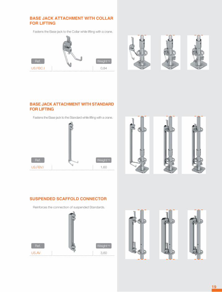
SUSPENDED SCAFFOLD CONNECTOR
Reinforces the connection of suspended Standards.
.Ref. .Weight (kg)
US.AV 3,60
BASE JACK ATTACHMENT WITH STANDARD FOR LIFTING
Fastens the Base jack to the Standard while lifting with a crane.
.Ref. .Weight (kg)
US.FBV.I 1,60
BASE JACK ATTACHMENT WITH COLLAR FOR LIFTING
Fastens the Base jack to the Collar while lifting with a crane.
.Ref. .Weight (kg)
US.FBC.I 0,84

20
INTERMEDIATE LEDGER DECK TO DECK
It is used as a deck’s bracket at the middle of a span.
.Ref. .Width (cm) .Weight (kg)
US.HZ.PP.0420 42 2,40US.HZ.PP.0730 73 3,50US.HZ.PP.1090 109 4,60
LEDGER
With two wedge heads to fit the rosettes, it is used as deck’s bracket and/or guard-rail. It always serves as a structural element.
.Ref. .Width (cm) .Weight (kg)
US.HZ.0420 42 1,80US.HZ.0730 73 2,90US.HZ.1090 109 4,10US.HZ.1400 140 5,20US.HZ.1570 157 5,70US.HZ.2070 207 7,40US.HZ.2570 257 9,10US.HZ.3070 307 10,90
INTERMEDIATE LEDGER TUBE TO TUBE
It is used as a deck’s bracket at the middle of a span.
.Ref. .Width (cm) .Weight (kg)
US.HZ.TT.0730 73 3,40US.HZ.TT.1090 109 4,60
LEDGER
U-type are used to assemble U-decks. The use of U-ledger and U-decks requires using US.FS.XXXX Deck Retainer on Page 29.
.Ref. .Width (cm) .Weight (kg)
US.HZ.U.0420 42 2,00US.HZ.U.0730 73 3,00
US.HZ.U.1090 109 5,10US.HZ.U.1400 140 6,20
US.HZ.U.1570 157 7,90US.HZ.U.2070 207 11,00US.HZ.U.2570 257 14,20

21
LEDGER 35º
Overcomes the non-covered angle of Ledgers in circular scaffolds (0º-35º).
.Ref. .Width (cm) & Direction .Weight (kg)
US.HZ.730.35.E 73 - Left 3,00US.HZ.730.35.D 73 - Right 3,00US.HZ.U.730.35.E 73 - Left 3,10US.HZ.U.730.35.D 73 - Right 3,10
BRIDGING LEDGER
For spans larger than 1,57 m, Ledgers are replaced by Bridging ledgers to bear higher loads. The use of U-bridging ledger and U-decks requiresusing US.FS.XXXX Deck Retainer on Page 29.
.Ref. .Width (cm) .Weight (kg)
US.VP.1570 157 10,20US.VP.2070 207 13,90US.VP.2570 257 17,50US.VP.3070 307 21,10US.VP.U.1570 157 10,10US.VP.U.2070 207 13,60US.VP.U.2570 257 17,10US.VP.U.3070 307 20,60

22
WALKWAY BEAM
Delimits 157 cm walkways and allows the upper assembly of a façade scaffold with 73 ou 109 cm width.
.Ref. .Width (cm) .Height (cm) .Weight (kg)
US.VP 157 50 20,80US.VP.U 157 50 20,70
LATTICE BEAM WITH 4 WEDGE HEADS
Used for increasing the load bearing capacity or to double the standard spans.
.Ref. .Width (cm) .Height (cm) .Weight (kg)
US.VS.1090 109 50 13,50
US.VS.3070 370 50 29,90
US.VS.4140 414 50 45,30
US.VS.5140 514 50 55,20
US.VS.6140 614 50 65,00
US.VS.U.4140 414 50 43,00
US.VS.U.5140 514 50 52,30
US.VS.U.6140 614 50 61,50
STEEL LATTICE BEAM
Used as bracket for decks on further scaffold assemblies such as suspended scaffolds, or as a reinforcement to bear heavy loads when the assembly is above ground.
.Ref. .Width (cm) .Height (cm) .Weight (kg)
AA.VP.2000 200 40 20,60AA.VP.3000 300 40 28,20AA.VP.4000 400 40 39,90AA.VP.5000 500 40 48,90AA.VP.6000 600 40 59,20AA.VP.5000.75 500 75 57,30AA.VP.6000.75 600 75 69,80
* AA.VP.EC Spigot for jointing lattice beam Page 42
23
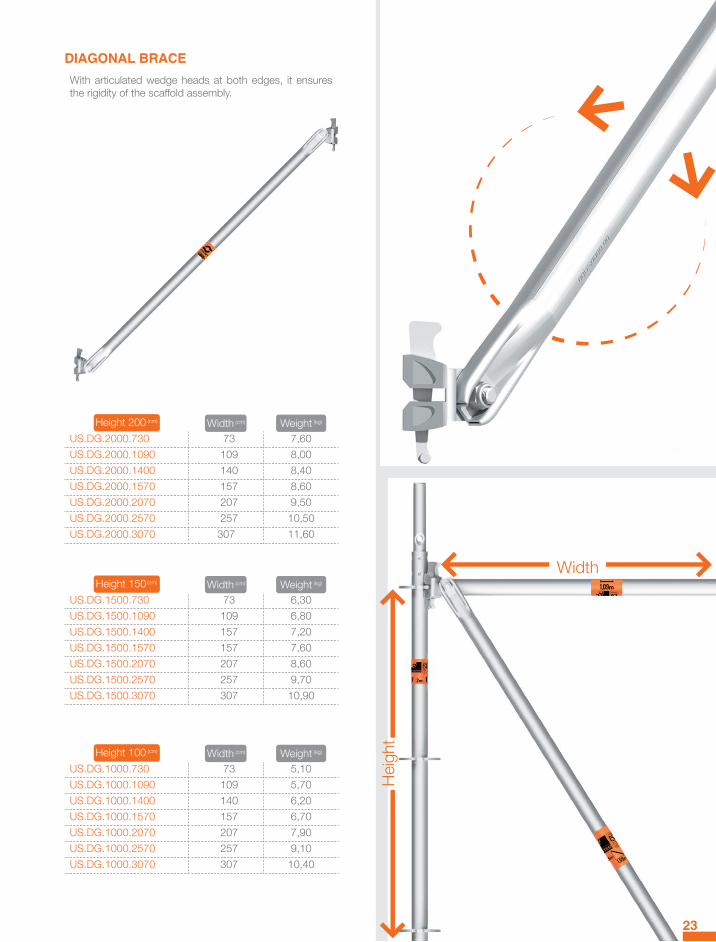
DIAGONAL BRACE
With articulated wedge heads at both edges, it ensures the rigidity of the scaffold assembly.
.Height 200 (cm) .Width (cm) .Weight (kg)
US.DG.2000.730 73 7,60US.DG.2000.1090 109 8,00US.DG.2000.1400 140 8,40US.DG.2000.1570 157 8,60US.DG.2000.2070 207 9,50US.DG.2000.2570 257 10,50US.DG.2000.3070 307 11,60
.Height 150 (cm) .Width (cm) .Weight (kg)
US.DG.1500.730 73 6,30US.DG.1500.1090 109 6,80US.DG.1500.1400 157 7,20US.DG.1500.1570 157 7,60US.DG.1500.2070 207 8,60US.DG.1500.2570 257 9,70US.DG.1500.3070 307 10,90
.Height 100 (cm) .Width (cm) .Weight (kg)
US.DG.1000.730 73 5,10US.DG.1000.1090 109 5,70US.DG.1000.1400 140 6,20US.DG.1000.1570 157 6,70US.DG.1000.2070 207 7,90US.DG.1000.2570 257 9,10US.DG.1000.3070 307 10,40
Heig
ht
Width

24
STEEL DECK
The most resistant and engineered steel deck by Catari. Designed for an intuitive and safe assembly, with anti-slip surface and lifting blocker. Sturdy and light.
.Ref. .Width (cm) .Standard Length (cm) .Class .Weight (kg)
US.PL.0730
32
73 6 6,20US.PL.1090 109 6 8,50US.PL.1400 140 6 10,60US.PL.1570 157 6 11,70US.PL.2070 207 6 15,00US.PL.2570 257 5 18,80US.PL.3070 307 5 22,00FA.PL.0730 73 6 5,80FA.PL.1090 109 6 8,20FA.PL.1400 140 6 10,30FA.PL.1570 157 6 11,40FA.PL..2070 207 6 14,60FA.PL.2570 257 5 18,40FA.PL.3070 307 5 21,70
CLASS & LOADS
.Class .Distributed load (kN/m2)
6 6,05 4,54 3,03 2,0

32 cm
19 cm
25
NON PERFORATED STEEL DECK
Used in assemblies where a completely closed floor is required.
.Ref. .Width (cm) .Length (cm) .Class .Weight (kg)
US.PL.320.0730
32
73 6 5,90US.PL.320.1090 109 6 7,90US.PL.320.1570 157 6 10,70US.PL.320.2070 207 6 13,50US.PL.320.2570 257 4 16,60US.PL.320.3070 307 3 19,50FA.PL.320.0730 73 6 5,60FA.PL.320.1570 157 6 10,30FA.PL.320.2070 207 6 13,20FA.PL.320.2570 257 4 16,30FA.PL.320.3070 307 3 19,20
SLIM STEEL DECK
Closes remnant gaps on spans.
.Ref. .Width (cm) .Length (cm) .Weight (kg)
US.PL.190.1090
19
109 6,90US.PL.190.1570 157 9,60US.PL.190.2070 207 12,40US.PL.190.2570 257 15,30US.PL.190.3070 307 18,10FA.PL.190.1570 157 9,40FA.PL.190.2070 207 12,20FA.PL.190.2570 257 15,10FA.PL.190.3070 307 17,90
73 c
m to
307
cm

61 cm
26
DOUBLE DECKS
Replaces two conventional Steel decks, having the advantage of reducing the weight and making the assemblage and dis-assemblage faster. The frame is made of aluminium and the floor can be plywood antislip or aluminium.
PLYWOOD
.Ref. .Width (cm) .Length (cm) .Class .Weight (kg)
US.PAM.1570
61
157 3 13,10US.PAM.2070 207 3 16,80US.PAM.2570 257 3 20,50US.PAM.3070 307 3 25,70FA.PAM.1570 157 3 12,70FA.PAM.2070 207 3 16,40FA.PAM.2570 257 3 20,10FA.PAM.3070 307 3 25,30
ALUMINIUM
.Ref. .Width (cm) .Length (cm) .Class .Weight (kg)
US.PAA.1570
61
157 3 11,40US.PAA.2070 207 3 14,70US.PAA.2570 257 3 17,80US.PAA.3070 307 3 22,40FA.PAA.1570 157 3 11,00FA.PAA.2070 207 3 14,30FA.PAA.2570 257 3 17,40FA.PAA.3070 307 3 22,00
ACCESS DECK 1,09 M
Used for spans of 109 cm.
.Ref. .Width (cm) .Length (cm) .Class .Weight (kg)
US.PA.1090 61 109 3 10,20US.PA.AL.1090 61 109 3 10,80AA.EA Aluminium ladder 3,20

27
ACCESS DECKS
With an aluminium ladder that allows a safe passage from one level to another. The aluminium frame with plywood antis-lip or aluminium floor, reduces the weight making it easier to assemble and disassemble. The access decks 2570 and 3070 have an integrated ladder.
PLYWOOD
.Ref. .Width (cm) .Length (cm) .Class .Weight (kg)
US.PA.2070
61
207 3 17,40US.PA.2570 257 3 24,10US.PA.3070 307 3 29,30FA.PA.2070 207 3 17,00FA.PA.2570 257 3 23,70FA.PA.3070 307 3 28,90AA.EA Aluminium ladder for US.PA.2070 and FA.PA.2070 3,20
ALUMINIUM
.Ref. .Width (cm) .Length (cm) .Class .Weight (kg)
US.PA.AL.2070
61
207 3 16,10US.PA.AL.2570 257 3 22,30US.PA.AL.3070 307 3 26,90FA.PA.AL.2070 207 3 15,80FA.PA.AL.2570 257 3 21,90FA.PA.AL.3070 307 3 26,50AA.EA Aluminium ladder for US.PA.AL.2070 and FA.PA.AL.2070 3,20
LATERAL ACCESS DECK
Access deck with lateral opening trap.
ALUMINIUM.Ref. .Width (cm) .Length (cm) .Class .Weight (kg)
US.PA.AL.LA.2070
61
207 3 14,80US.PA.AL.LA.2570 257 3 23,00US.PA.AL.LA.3070 307 3 27,50FA.PA.AL.LA.2070 207 3 14,40FA.PA.AL.LA.2570 257 3 22,60FA.PA.AL.LA.3070 307 3 27,10AA.EA Aluminium ladder for US.PA.AL.LA.2070 and FA.PA.AL.LA.2070 3,20

28
ANGULAR DECK 0/45º
Covers gaps between decks placed with angles up to 45º.
.Ref. .Width (cm) .Weight (kg)
US.PL.CA.0/45 61
6,10FA.PL.CA.0/45 6,40
CORNER DECK 90º
Covers interior corners of 90º.
.Ref. .Width (cm) .Weight (kg)
US.PL.CA.90 61 9,00
CONNECTION PLATFORM
Covers gaps between scaffolds.
.Ref. .Width (cm) .Weight (kg)
US.PL.LC 61
9,60FA.PL.LC 9,70

29
METALLIC TOE BOARD
Prevents objects from falling. Made of steel with special edge head for a perfect fitting.
.Ref. .Length (cm) .Weight (kg)
US.RPM.0420 42 1,30US.RPM.0730 73 2,10US.RPM.1090 109 3,00US.RPM.1400 140 3,70US.RPM.1570 157 4,20US.RPM.2070 207 5,40US.RPM.2570 257 8,20US.RPM.3070 307 9,80
WOOD TOE BOARD
Prevents objects from falling. Made of wood with special edge head for a perfect fitting.
.Ref. .Length (cm) .Weight (kg)
US.RP.0420 42 1,50US.RP.0730 73 2,50US.RP.1090 109 3,60US.RP.1400 140 4,60US.RP.1570 157 5,10US.RP.2070 207 6,60US.RP.2570 257 8,20US.RP.3070 307 9,70
DECK RETAINER
Prevents decks of being lifted involuntarily and prevents the accumulation of dirt in U-type.
.Ref. .Width (cm) .Weight (kg)
US.FS.0420 42 0,66US.FS.0730 73 1,30US.FS.1090 109 1,90US.FS.1400 140 2,50US.FS.1570 157 2,80US.FS.2070 207 4,50US.FS.2570 257 5,80US.FS.3070 307 7,10
3,07 m
1 m
62 cm
30
STAIRCASES
Lightweight aluminium staircase with an anti-slip surface, mainly used for assembling stair towers.
.Ref. .Width (cm) .Length (cm) .Weight (kg)
US.EP.2570 257 62 26,00US.EP.3070 307 62 30,80
US.EP.1000.620 When the flight is smaller than 200 cm (height), place it over two steel decks. 14,60
US.EP.2000.960.2570 257 96 40,50US.EP.2000.960.3070 307 96 48,20
US.EP.1000.960 When the flight is smaller than 200 cm (height), place it over two steel decks. 23,20
FA.EP.2570 257 62 25,70FA.EP.3070 307 62 30,50
FA.EP.1000.620 When the flight is smaller than 200 cm (height), place it over two steel decks. 14,50

257 cm
307 cm
31
HANDRAIL FOR STAIRCASE
Used as side protection on staircases.
.Ref. .Description .Weight (kg)
AA.CE.1000 100 cm (use with US.EP.1000.620) 5,70
AA.CE.2000200 cm (use with the others US.EP.
XXXX Staircases on Page 30 and/or FA.EP.XXXX)
8,40
UPSTAIRS GUARDRAIL
Used as side protection on the top landing of stair-towers.
.Ref. .Extension(cm) .Weight (kg)
US.CP Telescopic from 257 up to 307 cm 10,50

32
DEFINITIVE ADVANCE GUARDRAIL
Used as advanced side protection against falls during the assembly of the upcoming scaffold level. It remains in place after the assembly is finished.
.Ref. .Length (cm) .Weight (kg)
US.GCMD.730 73 5,90US.GCMD.1090 109 6,70US.GCMD.1570 157 9,10US.GCMD.2070 207 11,20US.GCMD.2570 257 12,90US.GCMD.3070 307 14,00

33
ADVANCE GUARDRAIL POST (ALUMINIUM)
Used as temporary advanced side protection against falls during the assembly of the upcoming scaffold level. It is dismantled after the assembly is finished.
.Ref. .Weight (kg)
AA.GCMP 4,90
ADVANCE GUARDRAIL (ALUMINIUM)
Used as temporary advanced side protection against falls during the assembly of the upcoming scaffold level. It is dismantled after the assembly is finished.
.Ref. .Extension(cm) .Weight (kg)
AA.TEGM.1570.2070 157 up to 207 (AL) 2,00AA.TEGM.2570.3070 257 up to 307 (AL) 2,60
34
CONSOLE BRACKETS
Expands the working surface by one, two or three supplementary Steel decks US.PL.XXXX. The use of U-console and U-decks requires using US.FS.XXXX Deck Retainer on Page 29.
.Ref. .Length (cm) .Weight (kg)
US.CL.320 32 4,60US.CL.730 73 6,20US.CL.1090 109 11,20US.CL.U.320 32 4,60US.CL.U.730 73 6,20US.CL.U.1090 109 11,20
BRACKET BRACE
Reinforces the Console bracket 730 when two or more levels are assembled above.
.Ref. .Length (cm) .Weight (kg)
AA.TC 73 7,20

35
CROSS HEAD JACK FOR H20 BEAM
Supports the H20 beams in false-work, transferring the load to the Standards without spigot.
.Ref. .Spindle height (cm) .Weight (kg)
US.CR Spindle 70 cm (Max. spindle: 47,5 cm) 6,20
HEAD JACK
Supports steel beams, transferring the load to the Standards without spigot.
.Ref. .Spindle height (cm) .Weight (kg)
US.CR.U Spindle 70 cm (Max. spindle: 47,5 cm) 6,90
ADJUSTABLE SPINDLE & U HEAD
Used with US.CU U head as support to steel beams, transferring the load to the Standards without spigot.
.Ref. .Description .Weight (kg)
US.FR.850 Spindle 85 cm (Max. spindle: 60 cm) 3,40US.CU U head 4,10
360 º
36
DOUBLE COUPLER
Connects two perpendicular tubes with 48,3 mm diameter each.
.Ref. .Weight (kg)
AA.OT.48 1,30
SWIVEL COUPLER
Connects two tubes with 48,3 mm diameter each. Allows 360º rotation positions.
.Ref. .Weight (kg)
AA.OG.48 1,30
ROSETTE COUPLER
Connects Ledgers or Diagonal braces between the rosettes of a Standard, increasing the range of US® possibilities.
.Ref. .Weight (kg)
AA.AROSE 1,20

37
LOCKING PIN (PIG TAIL)
Fastens two Standards.
.Ref. .Weight (kg)
AA.PS 0,08
HINGED PIN
Spring locking pin to fasten two Standards.
.Ref. .Weight (kg)
AA.PS.ML 0,05
TWIN WEDGE COUPLER
Connects two Standards increasing the load bearing capacity.
.Ref. .Weight (kg)
US.TD 0,90
360 º 360 º
38
CLAW COUPLER
Suspends scaffold tubes of diameter 48,3 mm on steel profiles. Used in pairs.
.Ref. .Weight (kg)
AA.AP.GA 1,10
SWIVEL COUPLER FOR PROFILE WITH BOLT
Suspends scaffold tubes of diameter 48,3 mm on steel profiles. Allows rotating positions and screwing. Used in pairs.
.Ref. .Weight (kg)
AA.APG 2,10
PROFILE COUPLER WITH BOLT
Suspends scaffold tubes of diameter 48,3 mm on steel profiles. Allows screwing. Used in pairs.
.Ref. .Weight (kg)
AA.AP 1,90

39
WALL TIE
Transmits the lateral loads of the scaffold to an anchor ground.
.Ref. .Length (cm) .Weight (kg)
AA.GA.250 25 1,10AA.GA.300 30 1,30AA.GA.500 50 2,10AA.GA.1000 100 3,90AA.GA.1500 150 5,80AA.GA.2000 200 7,60
SLEEVE COUPLER
Connects two tubes with diameter 48,3 mm in one axis. It must be used along with AA.EE Spigot for jointing .
.Ref. .Weight (kg)
AA.AD.48 1,40
RING SCREW
Attaches wall ties to an anchor ground.
.Ref. .Length (cm) .Weight (kg)
AA.OL.120 12 0,18AA.OL.190 19 0,24AA.OL.280 28 0,31AA.OL.350 35 0,37AA.OL.400 40 0,42
STOPPER
Works together with the AA.OL.XXX Ring Screw. It is indicated to fasten in solid elements, such as cement, concrete, ceramic tiles, etc.
.Ref. .Length (cm) .Weight (kg)
AA.BC.80 8 0,01AA.BC.100 10 0,01
SPIGOT FOR JOINTING
Connects two tubes with diameter 48,3 mm in one axis. It must be used along with AA.AD.48 Sleeve coupler.
.Ref. .Weight (kg)
AA.EE 0,85
* AA.EE Spigot for jointing

40
COUPLER WITH SPIGOT
Used when an additional Standard is needed at the middle of a span, increasing the number of US® possibilities.
.Ref. .Weight (kg)
US.AE.RP 1,80US.AE.RP.AS 1,80US.AE.U 1,70
U-LEDGER WITH COUPLERS
Assembled on Standard creating different levels of platforms.
.Ref. .Length (cm) .Weight (kg)
AA.CA.730 73 (non reinforced) 3.40AA.CA.1090 109 (reinforced) 5,50
JACK WITH COUPLER
Used when an additional Standard is needed at the middle of a span, allowing a correct height adjustment.
.Ref. .Height (cm) .Weight (kg)
AA.NA 70 3,50

41
CLAMP FOR RUBBISH RETAINING
Prevents rubbish from falling on the ground.
.Ref. .Tube Ø .Weight (kg)
AA.GRE Ø48 mm 12,30
CLIP FOR METAL SHEET FIXING
Fixes the metal sheet on the Clamp for rubbish retainer.
.Ref. .Tube Ø .Weight (kg)
AA.GFC.48 Ø48 mm 0,21
42
SPIGOT FOR JOINTING LATTICE BEAM
Connects AA.VP.XXXX Steel lattice beam on Page 22. It has four holes for fastening four AA.PP.12.65 Screw with nut.
.Ref. .Weight (kg)
AA.VP.EC 2,20
SCREW WITH NUT
M12*65.
.Ref. .Weight (kg)
AA.PP.12.65 0,09
SPIGOT FOR JOINTING STANDARDS
Connects US.VTS.XXXX Standard without spigot on Page 18. It has four holes for fastening four AA.PP.12.65 Screw with nut.
.Ref. .Weight (kg)
US.EC 2,40
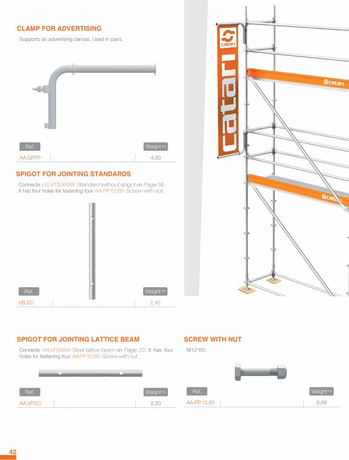
CLAMP FOR ADVERTISING
Supports an advertising canvas. Used in pairs.
.Ref. .Weight (kg)
AA.GFPP 4,30
43
COUPLER FOR STEPS
Creates the bracket for a supplementary step in staircases.
.Ref. .Weight (kg)
AA.AG 1,90
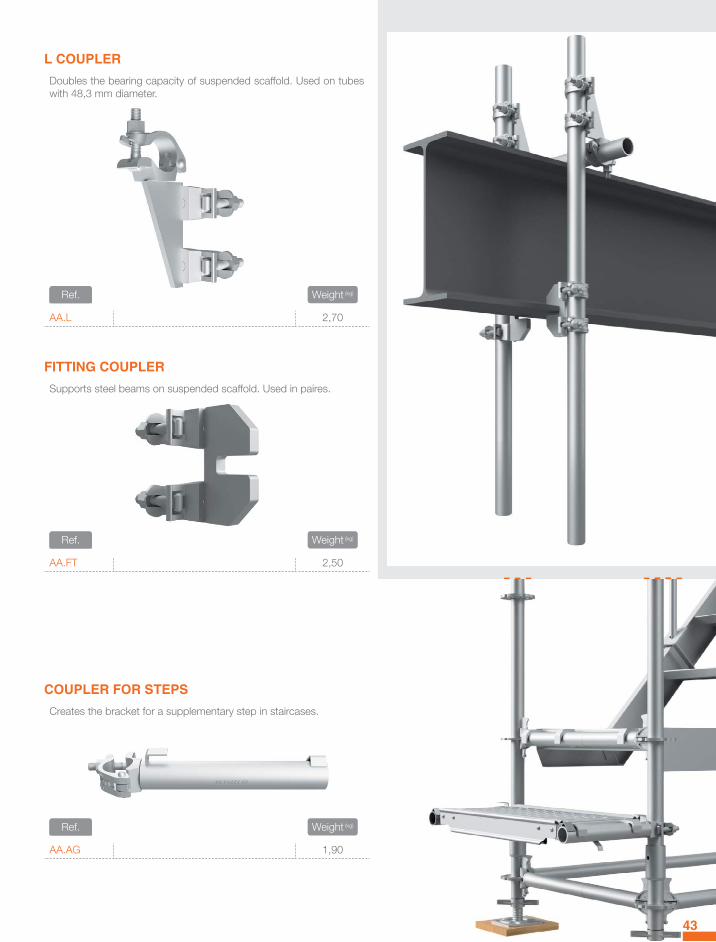
L COUPLER
Doubles the bearing capacity of suspended scaffold. Used on tubes with 48,3 mm diameter.
.Ref. .Weight (kg)
AA.L 2,70
FITTING COUPLER
Supports steel beams on suspended scaffold. Used in paires.
.Ref. .Weight (kg)
AA.FT 2,50

92 c
m
120 cm 85 cm
77 c
m
44
UNIVERSAL PALLET WITH MESH CRATE
To pack or transport Standards, Ledgers or Toe boards with a maximum of 150 cm and all sort of small or unbundled items such as couplers and spigots.They can be stacked and transported with crane or lift-truck; in the end they can be disassembled to save space.
.Ref. .Width (cm) .Length (cm) .Height (cm) .Weight (kg)
PU.RD 85 120 92 100,10
UNIVERSAL PALLET BASIC TYPE
To pack or transport Standards, Ledgers, Diagonal braces, Toe boards, etc.
.Ref. .Width (cm) .Length (cm) .Height (cm) .Weight (kg)
PU.B 85 120 92 44,70

45
CENTRAL SUPPORT FOR UNIVERSAL PALLET
To pack or transport Ledgers or Toe boards with 73 cm or 109 cm. The folded organisation assures an optimised space consumption and the maximum safety when 73 cm Ledgers or Toe board have to be displaced.
.Ref. .Width (cm) .Height (cm) .Weight (kg)
PU.SC 85 82 9,20
LATERAL MESH CRATE PANEL
.Ref. .Width (cm) .Height (cm) .Weight (kg)
PU.RL 85 71 7,70
FRONT MESH CRATE PANEL
.Ref. .Length (cm) .Height (cm) .Weight (kg)
PU.RF 120 77 10,90
BOTTOM FOR UNIVERSAL PALLET
.Ref. .Length (cm) .Width (cm) .Weight (kg)
PU.CF 120 85 18,20

46
WEDGES
Spare wedges for replacement.
.Ref. .Weight (kg)
US.TE.CU 25 units 3,25
RIVET FOR WEDGE
Spare wedges’ rivets for replacement.
.Ref. .Weight (kg)
US.TE.CR 100 units 0,30
T-BOLT FOR COUPLER
Spare T-Bolts for replacement.
.Ref. .Weight (kg)
AA.AB.PA 50 units 4,90
NUT FOR T-BOLT
Spare nuts of T-Bolts for replacement.
.Ref. .Weight (kg)
AA.AB.PO 100 units 4,40
SCAFFOLDING NET
For derbis netting, to protect passers-by and traffic of dirt caused by works on the scaffold.
.Ref. .Height (cm) .Length (cm)
AA.RM.4000 400 10.000
GALVANIZED TUBE
Diameter 48,3 mm and 3,2 mm thickness.
.Ref. .Length (cm) .Weight (kg)
AA.TU.0500.G 50 1,90AA.TU.1000.G 100 3,70AA.TU.1500.G 150 5,60AA.TU.2000.G 200 7,40AA.TU.2500.G 250 9,40AA.TU.3000.G 300 11,20AA.TU.4000.G 400 15,00AA.TU.5000.G 500 18,70AA.TU.6000.G 600 22,30
solutions holding your ideas.

www.catari.pt
MADE IN EUROPEAN UNION
PORTUGALZona industrial do Rossio - Av. da Industria3730-600 Vale de Cambra
solutions holding your ideas.
The
imag
es a
re fo
r illu
stra
tion
purp
oses
onl
y an
d m
ay n
ot p
erfe
ctly
or a
ccur
ately
de
pict
a re
alist
ic ob
ject o
r pro
cess
. The
illus
tratio
ns a
re p
urpo
sely
desig
ned
to
dem
onst
rate
a p
rincip
le or
seq
uenc
e of
ste
ps s
o th
at th
e vie
wer
has
a b
ette
r un
ders
tand
ing.
De
tails
may
be
simpl
ified
or o
mitt
ed, s
cale
may
be
resiz
ed.
© C
atar
i 201
7Ar
t dire
ctor
: Sté
phan
e Le
iteAl
l con
tent
on
this
cata
logu
e, s
uch
as te
xt, g
raph
ics, l
ogos
, and
imag
es
is th
e pr
oper
ty o
f Cat
ari In
dust
ria, S
.A. o
r its
con
tent
sup
plier
s an
d pr
otec
ted
by c
opyr
ight
law
of t
he E
urop
ean
Unio
n.
phone: (+351) 256 420 890e-mail: [email protected]