Embed Size (px)
Citation preview
2-17
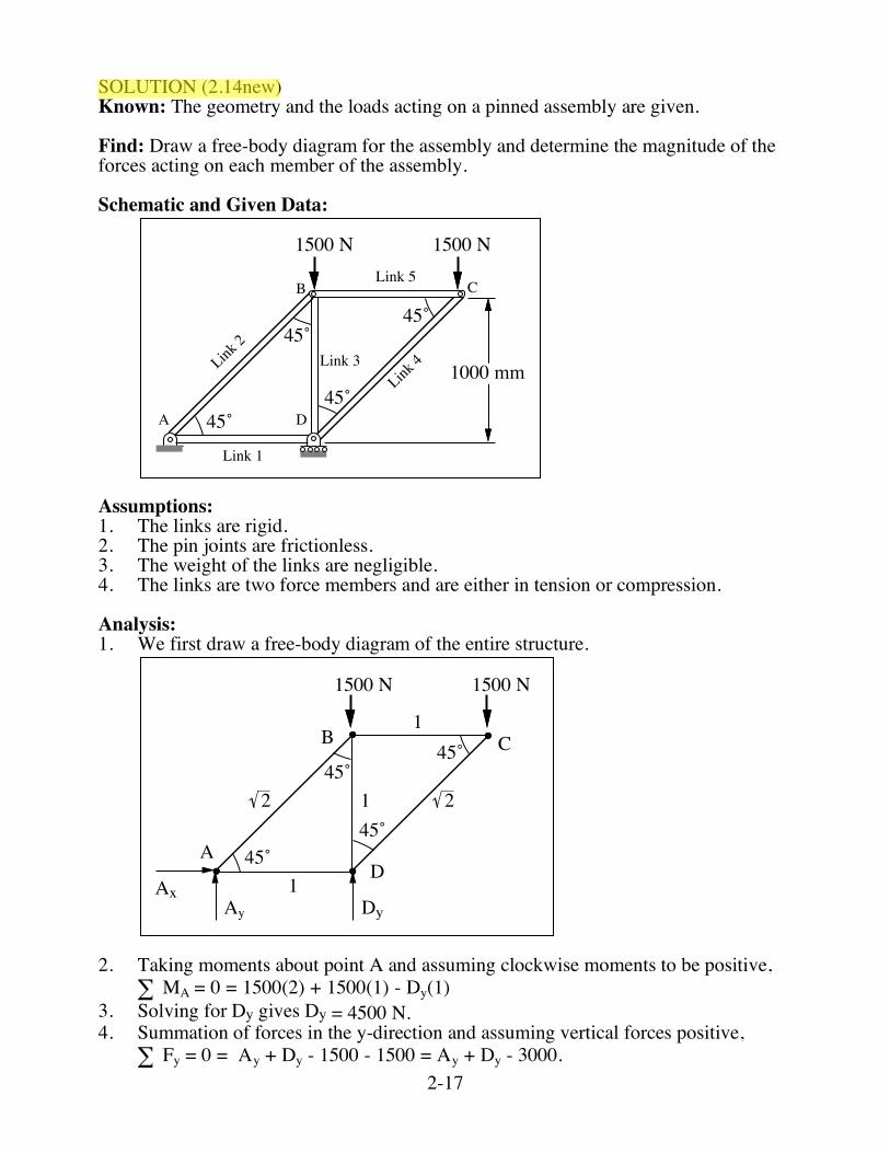
SOLUTION (2.14new) Known: The geometry and the loads acting on a pinned assembly are given. Find: Draw a free-body diagram for the assembly and determine the magnitude of the forces acting on each member of the assembly. Schematic and Given Data:
45˚
45˚
1000 mm
1500 N 1500 N
45˚
45˚A D
B CLink 5
Link 3
Link 1
Link 2
Link 4
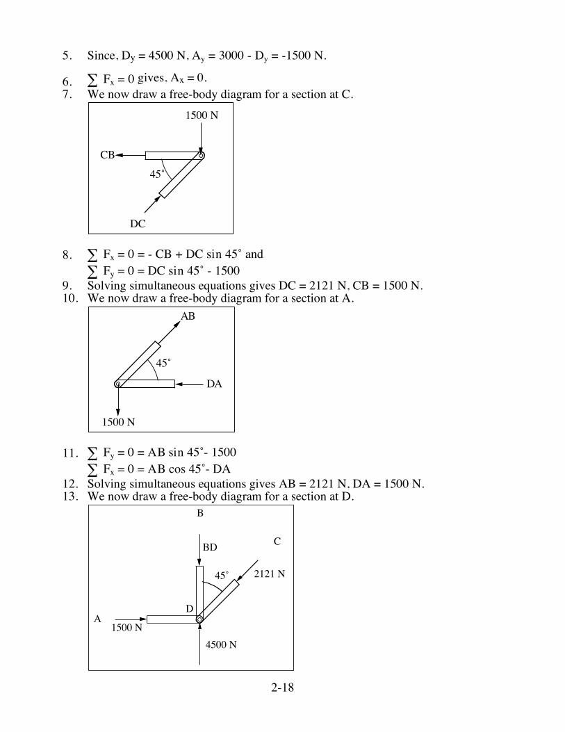
Assumptions: 1. The links are rigid. 2. The pin joints are frictionless. 3. The weight of the links are negligible. 4. The links are two force members and are either in tension or compression. Analysis: 1. We first draw a free-body diagram of the entire structure.
45˚
45˚
1500 N 1500 N
45˚
45˚A
D
B C1
1
1
2 2
Ay
AxDy
2. Taking moments about point A and assuming clockwise moments to be positive, MA = 0 = 1500(2) + 1500(1) - Dy(1)! 3. Solving for Dy gives Dy = 4500 N. 4. Summation of forces in the y-direction and assuming vertical forces positive,
Fy = 0 = Ay + Dy - 1500 - 1500 = Ay + Dy - 3000.!
2-18
5. Since, Dy = 4500 N, Ay = 3000 - Dy = -1500 N.
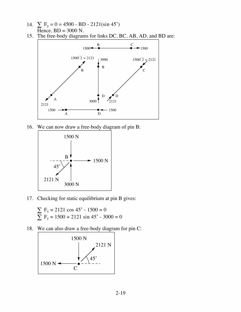
6. Fx = 0! gives, Ax = 0. 7. We now draw a free-body diagram for a section at C.
45˚
1500 N
DC
CB
8. Fx = 0 = - CB + DC sin 45˚ and!
Fy = 0 = DC sin 45˚ - 1500!
9. Solving simultaneous equations gives DC = 2121 N, CB = 1500 N. 10. We now draw a free-body diagram for a section at A.
45˚
1500 N
AB
DA
11. Fy = 0 = AB sin 45˚- 1500!
Fx = 0 = AB cos 45˚- DA!
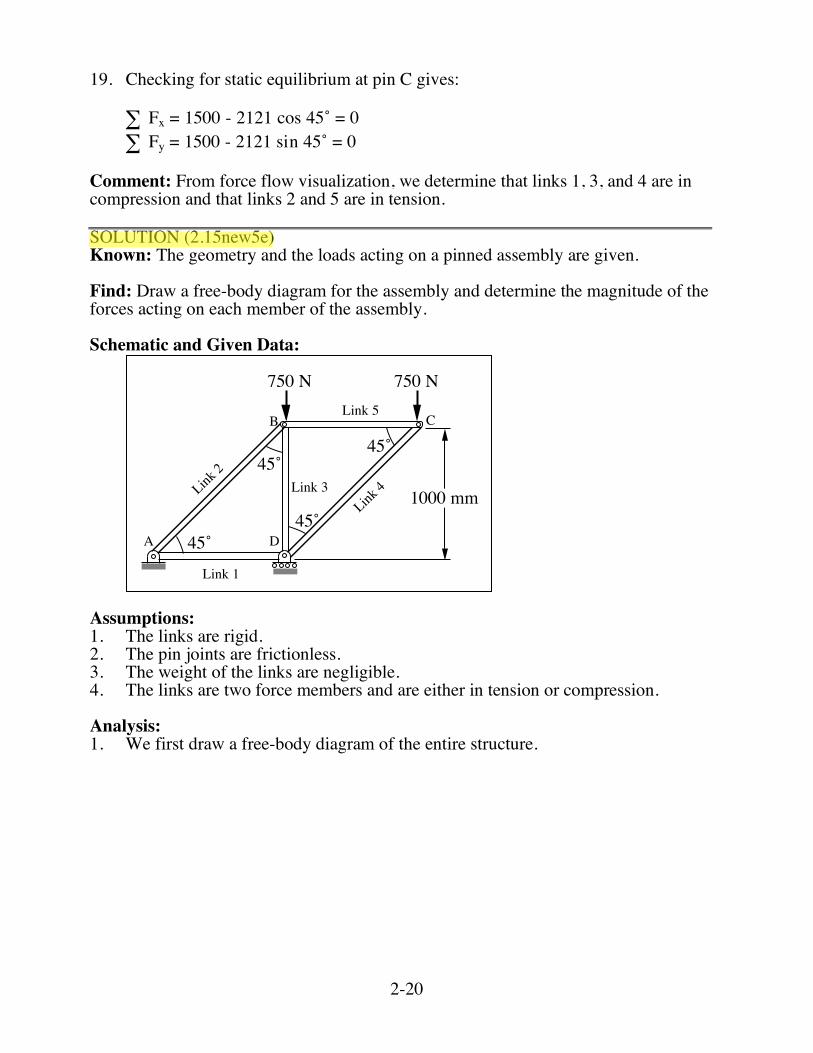
12. Solving simultaneous equations gives AB = 2121 N, DA = 1500 N. 13. We now draw a free-body diagram for a section at D.
45˚
1500 N
2121 N
BD
D
B
C
A
4500 N
2-19
14. Fy = 0 = 4500 - BD - 2121(sin 45˚)! Hence, BD = 3000 N. 15. The free-body diagrams for links DC, BC, AB, AD, and BD are:
B
A
1500 2 = 2121
2121
B C1500 1500
D
B
3000
3000
DA15001500
C
D
1500 2 = 2121
2121
16. We can now draw a free-body diagram of pin B:
B
2121 N3000 N
1500 N
1500 N
45˚
17. Checking for static equilibrium at pin B gives: Fx = 2121 cos 45˚ - 1500 = 0! Fy = 1500 + 2121 sin 45˚ - 3000 = 0! 18. We can also draw a free-body diagram for pin C:
C
2121 N
1500 N
1500 N
45˚
2-20
19. Checking for static equilibrium at pin C gives: Fx = 1500 - 2121 cos 45˚ = 0! Fy = 1500 - 2121 sin 45˚ = 0! Comment: From force flow visualization, we determine that links 1, 3, and 4 are in compression and that links 2 and 5 are in tension. SOLUTION (2.15new5e) Known: The geometry and the loads acting on a pinned assembly are given. Find: Draw a free-body diagram for the assembly and determine the magnitude of the forces acting on each member of the assembly. Schematic and Given Data:
45˚
45˚
1000 mm
750 N 750 N
45˚
45˚A D
B CLink 5
Link 3
Link 1
Link 2
Link 4
Assumptions: 1. The links are rigid. 2. The pin joints are frictionless. 3. The weight of the links are negligible. 4. The links are two force members and are either in tension or compression. Analysis: 1. We first draw a free-body diagram of the entire structure.
2-21
45˚
45˚
750 N 750 N
45˚
45˚A
D
B C1
1
1
2 2
Ay
AxDy
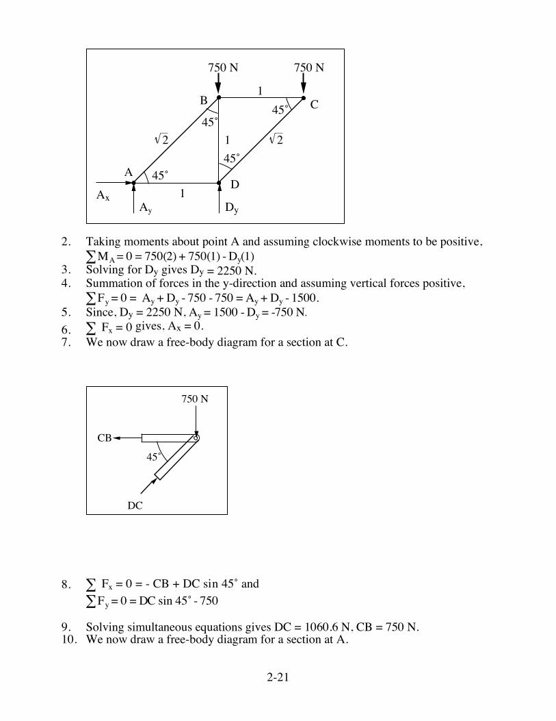
2. Taking moments about point A and assuming clockwise moments to be positive, !MA= 0 = 750(2) + 750(1) - Dy(1) 3. Solving for Dy gives Dy = 2250 N. 4. Summation of forces in the y-direction and assuming vertical forces positive,
!Fy = 0 = Ay + Dy - 750 - 750 = Ay + Dy - 1500. 5. Since, Dy = 2250 N, Ay = 1500 -Dy = -750 N. 6. Fx = 0! gives, Ax = 0. 7. We now draw a free-body diagram for a section at C.
45˚
750 N
DC
CB
8. Fx = 0 = - CB + DC sin 45˚ and!
!Fy = 0 = DC sin 45˚ - 750 9. Solving simultaneous equations gives DC = 1060.6 N, CB = 750 N. 10. We now draw a free-body diagram for a section at A.
2-22
45˚
750 N
AB
DA
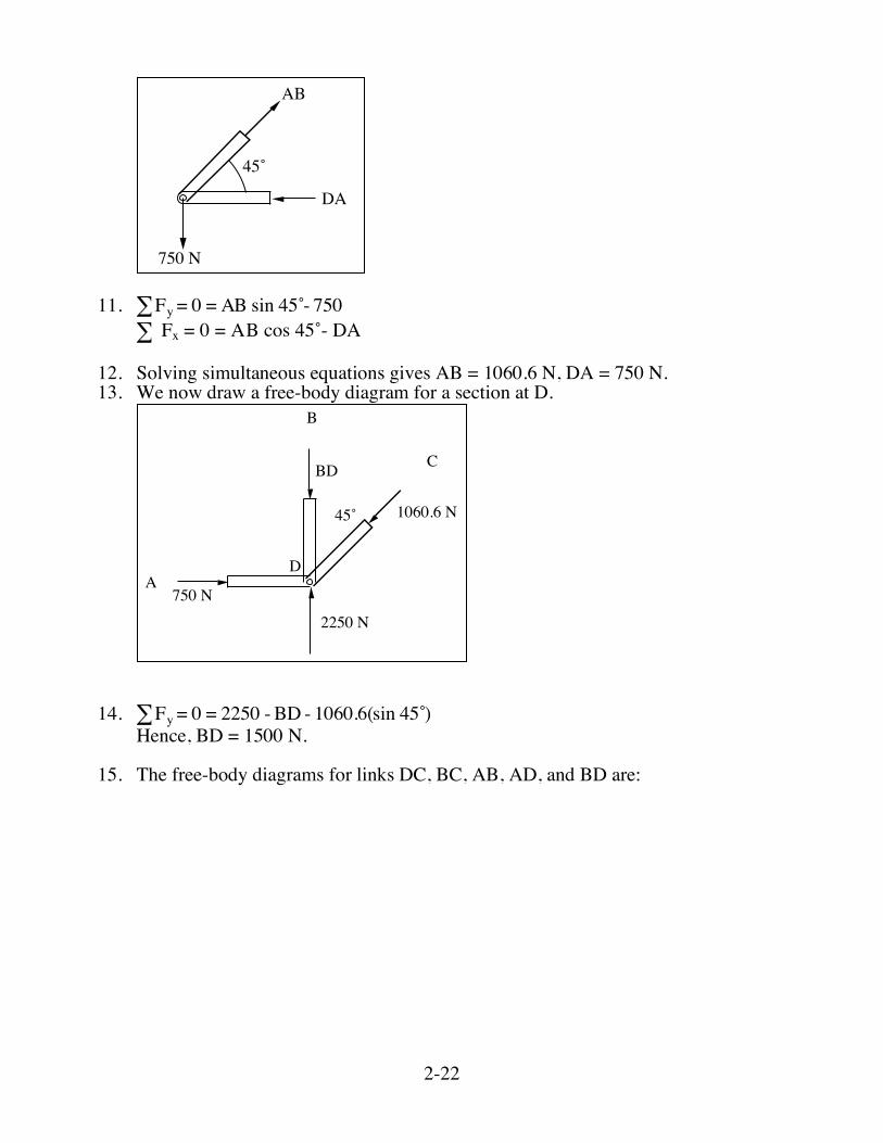
11. !Fy = 0 = AB sin 45 -̊ 750
Fx = 0 = AB cos 45˚- DA!
12. Solving simultaneous equations gives AB = 1060.6 N, DA = 750 N. 13. We now draw a free-body diagram for a section at D.
45˚
750 N
1060.6 N
BD
D
B
C
A
2250 N
14. !Fy = 0 = 2250 - BD - 1060.6(sin 45 )̊ Hence, BD = 1500 N. 15. The free-body diagrams for links DC, BC, AB, AD, and BD are:
2-23
B
A
B C750 750
D
B
1500
DA
C
D
1060.6
1060.6
1060.6
1060.6
750 750
1500
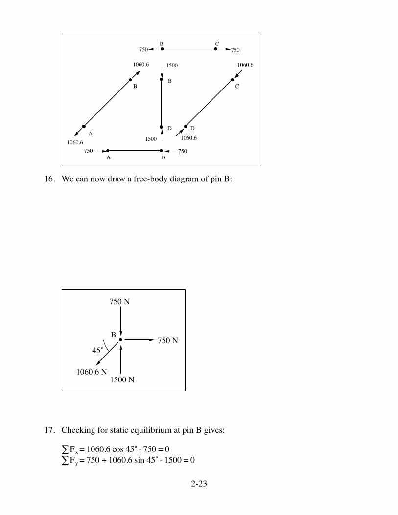
16. We can now draw a free-body diagram of pin B:
B
1060.6 N1500 N
750 N
750 N
45˚
17. Checking for static equilibrium at pin B gives: !Fx = 1060.6 cos 45˚ - 750 = 0 !Fy = 750 + 1060.6 sin 45˚ - 1500 = 0
2-24
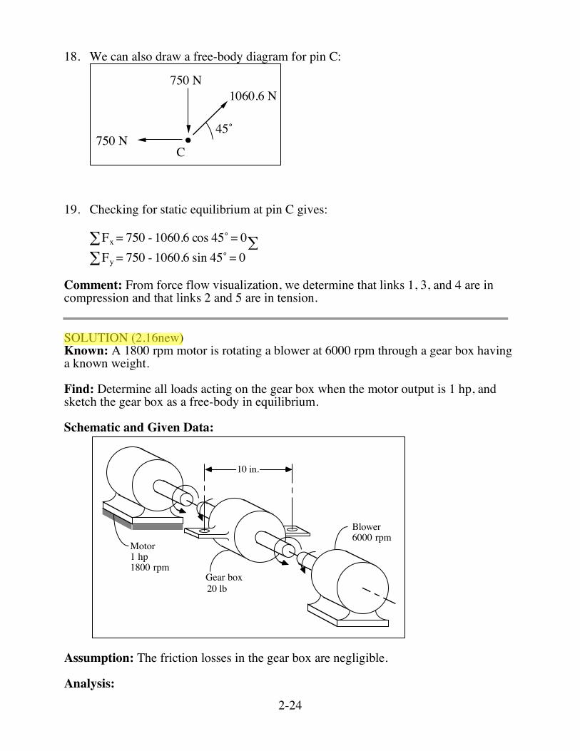
18. We can also draw a free-body diagram for pin C:
C
1060.6 N
750 N
750 N
45˚
19. Checking for static equilibrium at pin C gives:
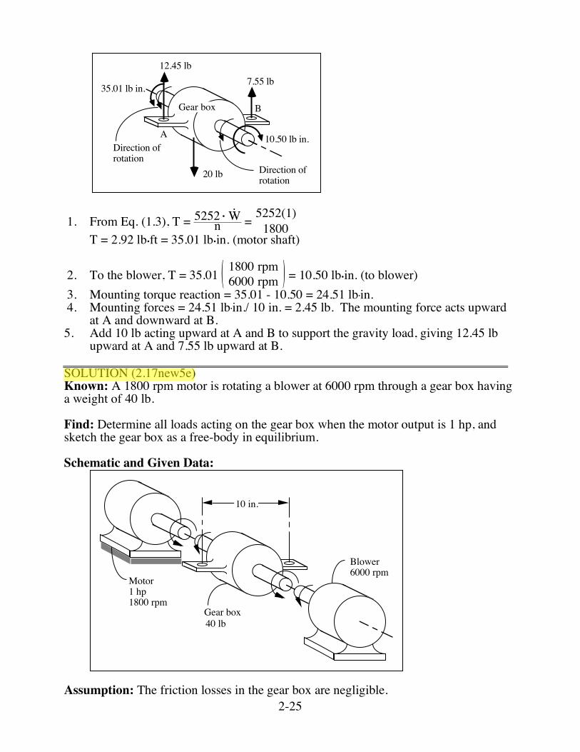
!Fx = 750 - 1060.6 cos 45˚ = 0! !Fy = 750 - 1060.6 sin 45˚ = 0 Comment: From force flow visualization, we determine that links 1, 3, and 4 are in compression and that links 2 and 5 are in tension. SOLUTION (2.16new) Known: A 1800 rpm motor is rotating a blower at 6000 rpm through a gear box having a known weight. Find: Determine all loads acting on the gear box when the motor output is 1 hp, and sketch the gear box as a free-body in equilibrium. Schematic and Given Data:
10 in.
Gear box
Blower6000 rpm
Motor1 hp1800 rpm
20 lb
Assumption: The friction losses in the gear box are negligible. Analysis:
2-25
Gear box
20 lb
10.50 lb in.
7.55 lb12.45 lb
35.01 lb in.
A
B
Direction of rotation
Direction of rotation
1. From Eq. (1.3), T = 5252 • Wn = 5252(1)1800
T = 2.92 lb•ft = 35.01 lb•in. (motor shaft)
2. To the blower, T = 35.01 ( )1800 rpm6000 rpm = 10.50 lb•in. (to blower)
3. Mounting torque reaction = 35.01 - 10.50 = 24.51 lb•in. 4. Mounting forces = 24.51 lb•in./ 10 in. = 2.45 lb. The mounting force acts upward
at A and downward at B. 5. Add 10 lb acting upward at A and B to support the gravity load, giving 12.45 lb
upward at A and 7.55 lb upward at B. SOLUTION (2.17new5e) Known: A 1800 rpm motor is rotating a blower at 6000 rpm through a gear box having a weight of 40 lb. Find: Determine all loads acting on the gear box when the motor output is 1 hp, and sketch the gear box as a free-body in equilibrium. Schematic and Given Data:
10 in.
Gear box
Blower6000 rpm
Motor1 hp1800 rpm
40 lb
Assumption: The friction losses in the gear box are negligible.
2-26
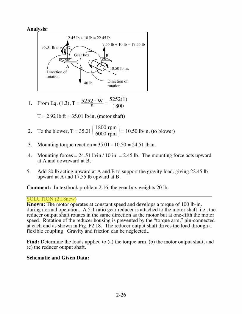
Analysis:
Gear box
40 lb
10.50 lb in.
7.55 lb + 10 lb = 17.55 lb12.45 lb + 10 lb = 22.45 lb
35.01 lb in.
A
B
Direction of rotation
Direction of rotation
1. From Eq. (1.3), T = 5252 • Wn =
5252(1)1800
T = 2.92 lb•ft = 35.01 lb•in. (motor shaft)
2. To the blower, T = 35.01 ( )1800 rpm6000 rpm = 10.50 lb•in. (to blower)
3. Mounting torque reaction = 35.01 - 10.50 = 24.51 lb•in. 4. Mounting forces = 24.51 lb•in./ 10 in. = 2.45 lb. The mounting force acts upward
at A and downward at B. 5. Add 20 lb acting upward at A and B to support the gravity load, giving 22.45 lb
upward at A and 17.55 lb upward at B. Comment: In textbook problem 2.16, the gear box weights 20 lb. SOLUTION (2.18new) Known: The motor operates at constant speed and develops a torque of 100 lb-in. during normal operation. A 5:1 ratio gear reducer is attached to the motor shaft; i.e., the reducer output shaft rotates in the same direction as the motor but at one-fifth the motor speed. Rotation of the reducer housing is prevented by the “torque arm,” pin-connected at each end as shown in Fig. P2.18. The reducer output shaft drives the load through a flexible coupling. Gravity and friction can be neglected.. Find: Determine the loads applied to (a) the torque arm, (b) the motor output shaft, and (c) the reducer output shaft. Schematic and Given Data:
2-27
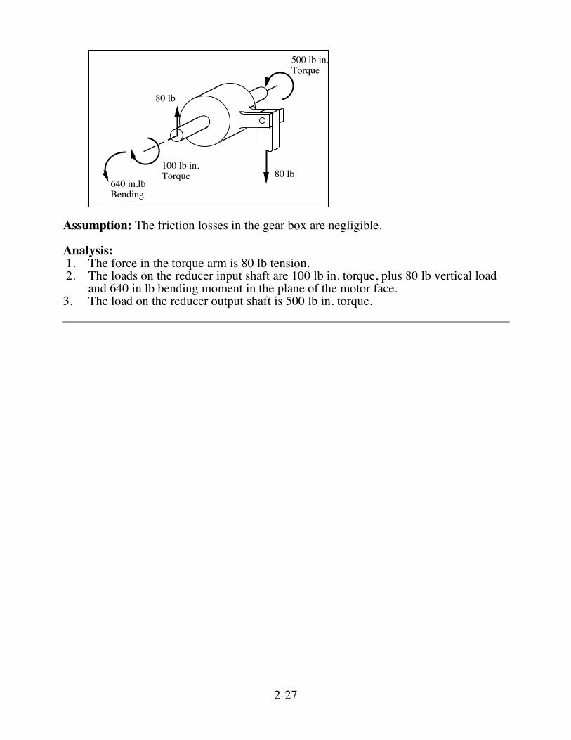
500 lb in.Torque
80 lb
80 lb
100 lb in.Torque
640 in.lb Bending
Assumption: The friction losses in the gear box are negligible. Analysis: 1. The force in the torque arm is 80 lb tension. 2. The loads on the reducer input shaft are 100 lb in. torque, plus 80 lb vertical load
and 640 in lb bending moment in the plane of the motor face. 3. The load on the reducer output shaft is 500 lb in. torque.
2-35
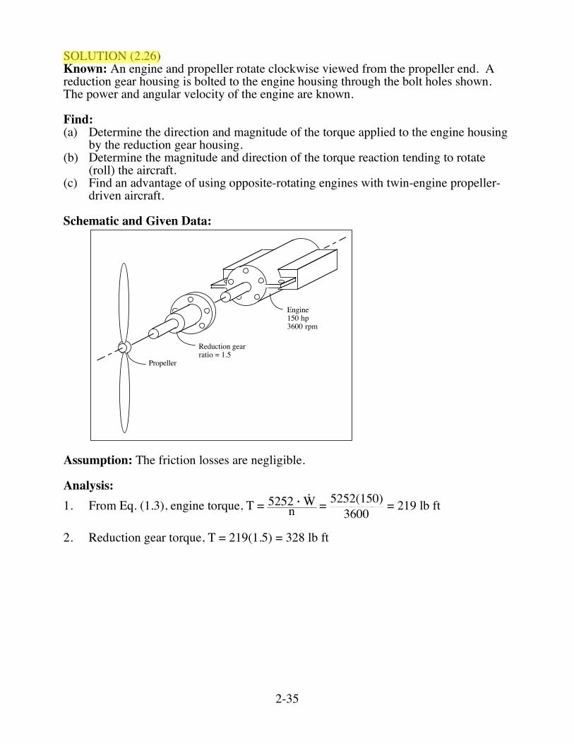
SOLUTION (2.26) Known: An engine and propeller rotate clockwise viewed from the propeller end. A reduction gear housing is bolted to the engine housing through the bolt holes shown. The power and angular velocity of the engine are known. Find: (a) Determine the direction and magnitude of the torque applied to the engine housing
by the reduction gear housing. (b) Determine the magnitude and direction of the torque reaction tending to rotate
(roll) the aircraft. (c) Find an advantage of using opposite-rotating engines with twin-engine propeller-
driven aircraft. Schematic and Given Data:
Engine150 hp3600 rpm
Reduction gearratio = 1.5
Propeller
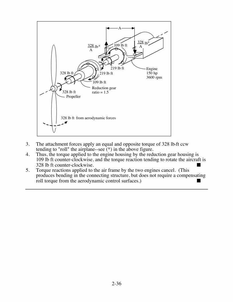
Assumption: The friction losses are negligible. Analysis: 1. From Eq. (1.3), engine torque, T = 5252 • W
n = 5252(150)3600 = 219 lb ft 2. Reduction gear torque, T = 219(1.5) = 328 lb ft
2-36
Engine150 hp3600 rpm
Reduction gearratio = 1.5
Propeller
A
328 lb ft
328 lb ft from aerodynamic forces
328 lb ft
109 lb ft
109 lb ft
219 lb ft219 lb ft
328A
lb328A
lb**
3. The attachment forces apply an equal and opposite torque of 328 lb•ft ccw
tending to "roll" the airplane--see (*) in the above figure. 4. Thus, the torque applied to the engine housing by the reduction gear housing is
109 lb ft counter-clockwise, and the torque reaction tending to rotate the aircraft is 328 lb ft counter-clockwise. ■
5. Torque reactions applied to the air frame by the two engines cancel. (This produces bending in the connecting structure, but does not require a compensating roll torque from the aerodynamic control surfaces.) ■
2-42
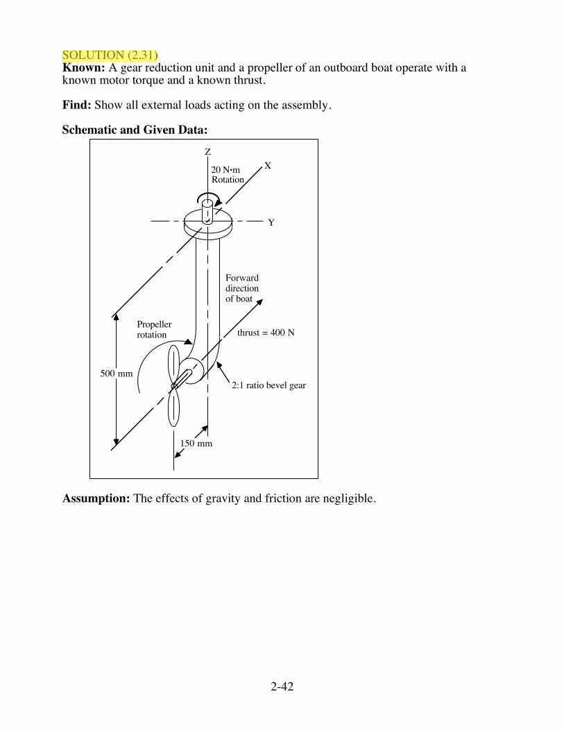
SOLUTION (2.31) Known: A gear reduction unit and a propeller of an outboard boat operate with a known motor torque and a known thrust. Find: Show all external loads acting on the assembly. Schematic and Given Data:
500 mm
Forwarddirectionof boat
thrust = 400 N
2:1 ratio bevel gear
150 mm
Y
XZ
20 N•mRotation
Propellerrotation
Assumption: The effects of gravity and friction are negligible.
2-43
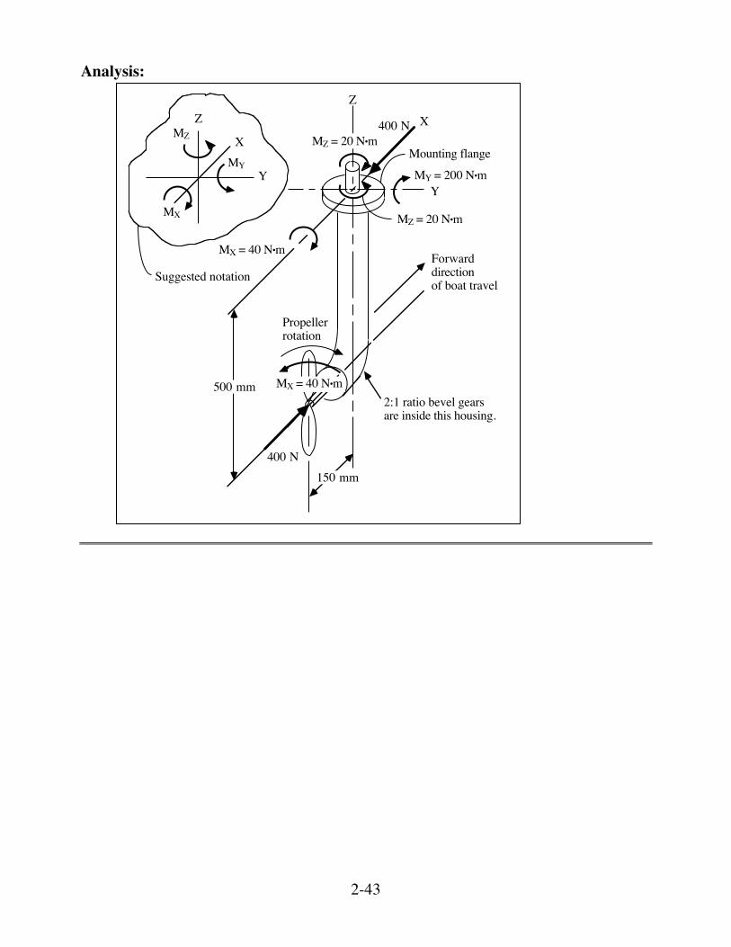
Analysis:
500 mm
Forwarddirectionof boat travel
2:1 ratio bevel gearsare inside this housing.
150 mm
Y
X
Z
MZ = 20 N•m
MZ = 20 N•m
MY = 200 N•m
MX = 40 N•m
MX = 40 N•m
400 N
Propeller rotation
Mounting flange
400 N
Suggested notation
Y
Z
X
MX
MZ
MY
2-44
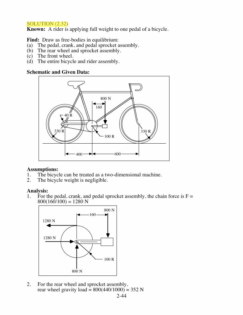
SOLUTION (2.32) Known: A rider is applying full weight to one pedal of a bicycle. Find: Draw as free-bodies in equilibrium: (a) The pedal, crank, and pedal sprocket assembly. (b) The rear wheel and sprocket assembly. (c) The front wheel. (d) The entire bicycle and rider assembly. Schematic and Given Data:
400 600
160
800 N
330 R100 R
40 R
330 R
Assumptions: 1. The bicycle can be treated as a two-dimensional machine. 2. The bicycle weight is negligible. Analysis: 1. For the pedal, crank, and pedal sprocket assembly, the chain force is F =
800(160/100) = 1280 N
100 R
1601280 N
1280 N
800 N
800 N
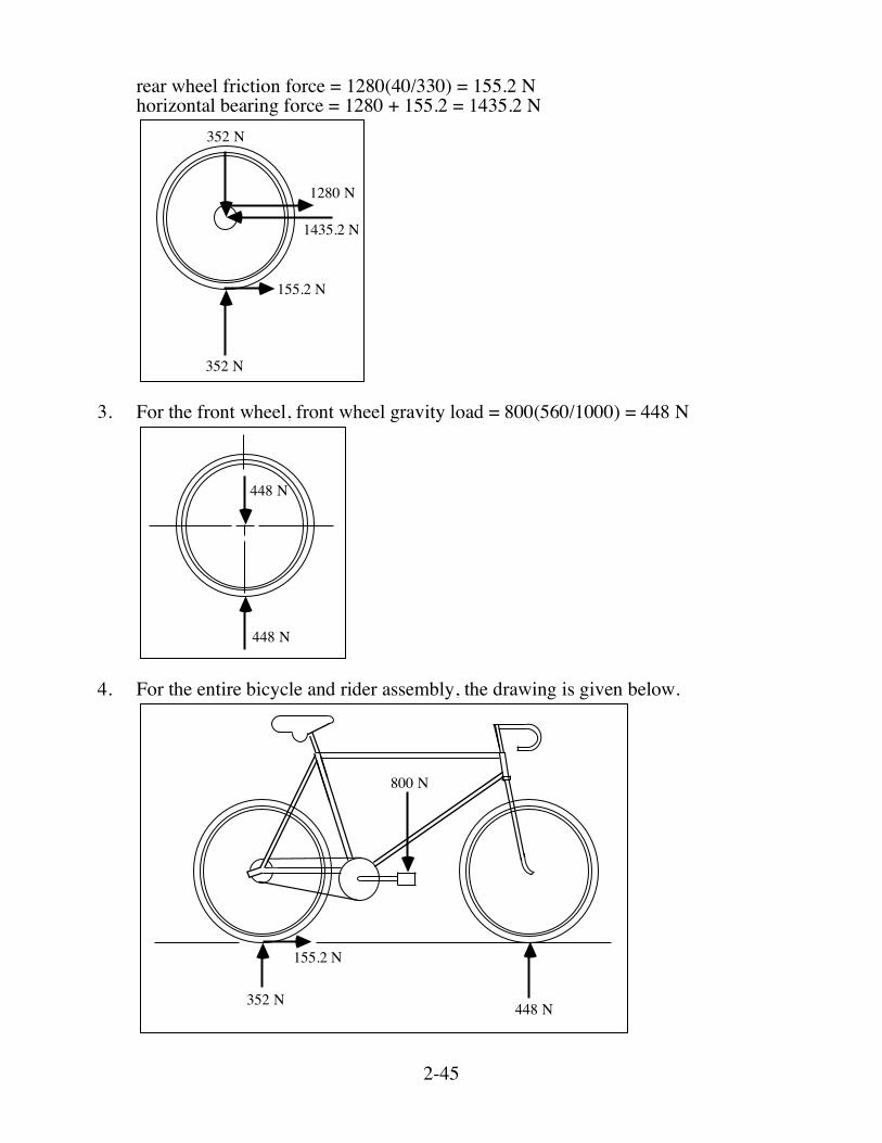
2. For the rear wheel and sprocket assembly, rear wheel gravity load = 800(440/1000) = 352 N
2-45
rear wheel friction force = 1280(40/330) = 155.2 N horizontal bearing force = 1280 + 155.2 = 1435.2 N
352 N
352 N
155.2 N
1435.2 N
1280 N
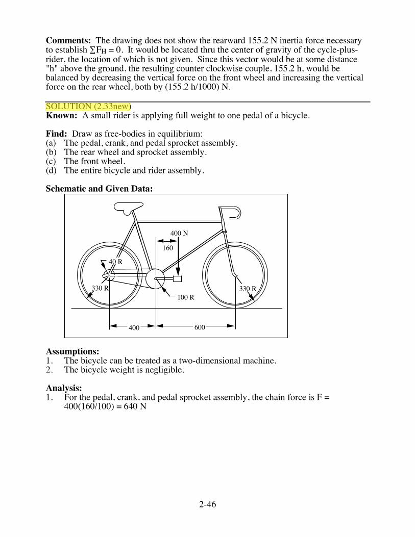
3. For the front wheel, front wheel gravity load = 800(560/1000) = 448 N
448 N
448 N
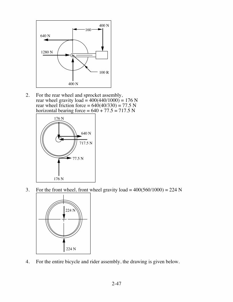
4. For the entire bicycle and rider assembly, the drawing is given below.
800 N
352 N
155.2 N
448 N
2-46
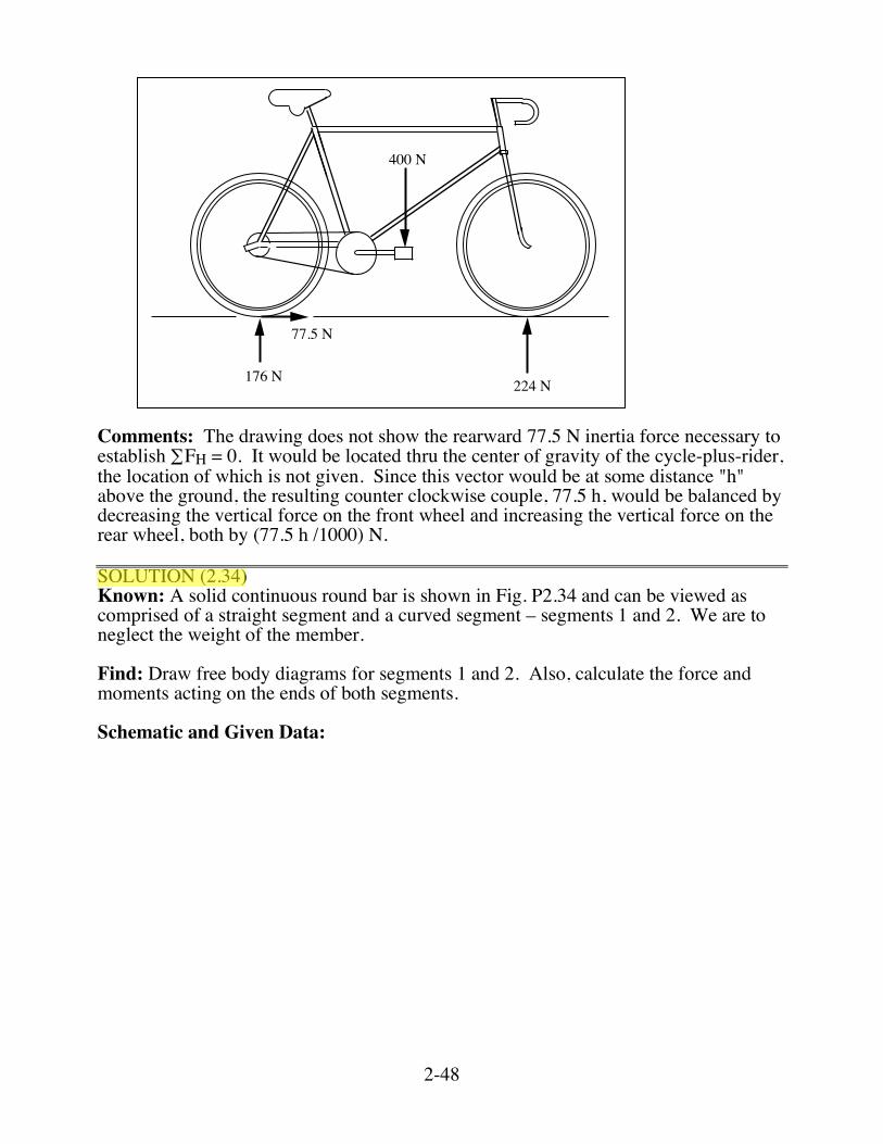
Comments: The drawing does not show the rearward 155.2 N inertia force necessary to establish ∑FH = 0. It would be located thru the center of gravity of the cycle-plus-rider, the location of which is not given. Since this vector would be at some distance "h" above the ground, the resulting counter clockwise couple, 155.2 h, would be balanced by decreasing the vertical force on the front wheel and increasing the vertical force on the rear wheel, both by (155.2 h/1000) N. SOLUTION (2.33new) Known: A small rider is applying full weight to one pedal of a bicycle. Find: Draw as free-bodies in equilibrium: (a) The pedal, crank, and pedal sprocket assembly. (b) The rear wheel and sprocket assembly. (c) The front wheel. (d) The entire bicycle and rider assembly. Schematic and Given Data:
400 600
160
400 N
330 R100 R
40 R
330 R
Assumptions: 1. The bicycle can be treated as a two-dimensional machine. 2. The bicycle weight is negligible. Analysis: 1. For the pedal, crank, and pedal sprocket assembly, the chain force is F =
400(160/100) = 640 N
2-47
100 R
160640 N
1280 N
400 N
400 N
2. For the rear wheel and sprocket assembly, rear wheel gravity load = 400(440/1000) = 176 N rear wheel friction force = 640(40/330) = 77.5 N horizontal bearing force = 640 + 77.5 = 717.5 N
176 N
176 N
77.5 N
717.5 N
640 N
3. For the front wheel, front wheel gravity load = 400(560/1000) = 224 N
224 N
224 N
4. For the entire bicycle and rider assembly, the drawing is given below.
2-48
400 N
176 N
77.5 N
224 N
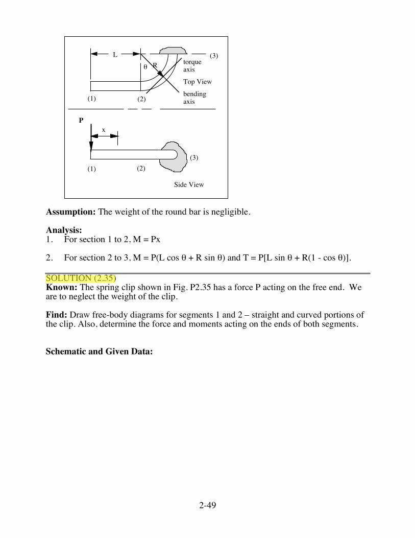
Comments: The drawing does not show the rearward 77.5 N inertia force necessary to establish ∑FH = 0. It would be located thru the center of gravity of the cycle-plus-rider, the location of which is not given. Since this vector would be at some distance "h" above the ground, the resulting counter clockwise couple, 77.5 h, would be balanced by decreasing the vertical force on the front wheel and increasing the vertical force on the rear wheel, both by (77.5 h /1000) N. SOLUTION (2.34) Known: A solid continuous round bar is shown in Fig. P2.34 and can be viewed as comprised of a straight segment and a curved segment – segments 1 and 2. We are to neglect the weight of the member. Find: Draw free body diagrams for segments 1 and 2. Also, calculate the force and moments acting on the ends of both segments. Schematic and Given Data:
2-49
(1)
Top View
x
R!
P
Side View
(2)
(3)
(1) (2)(3)
bendingaxis
torqueaxis
L
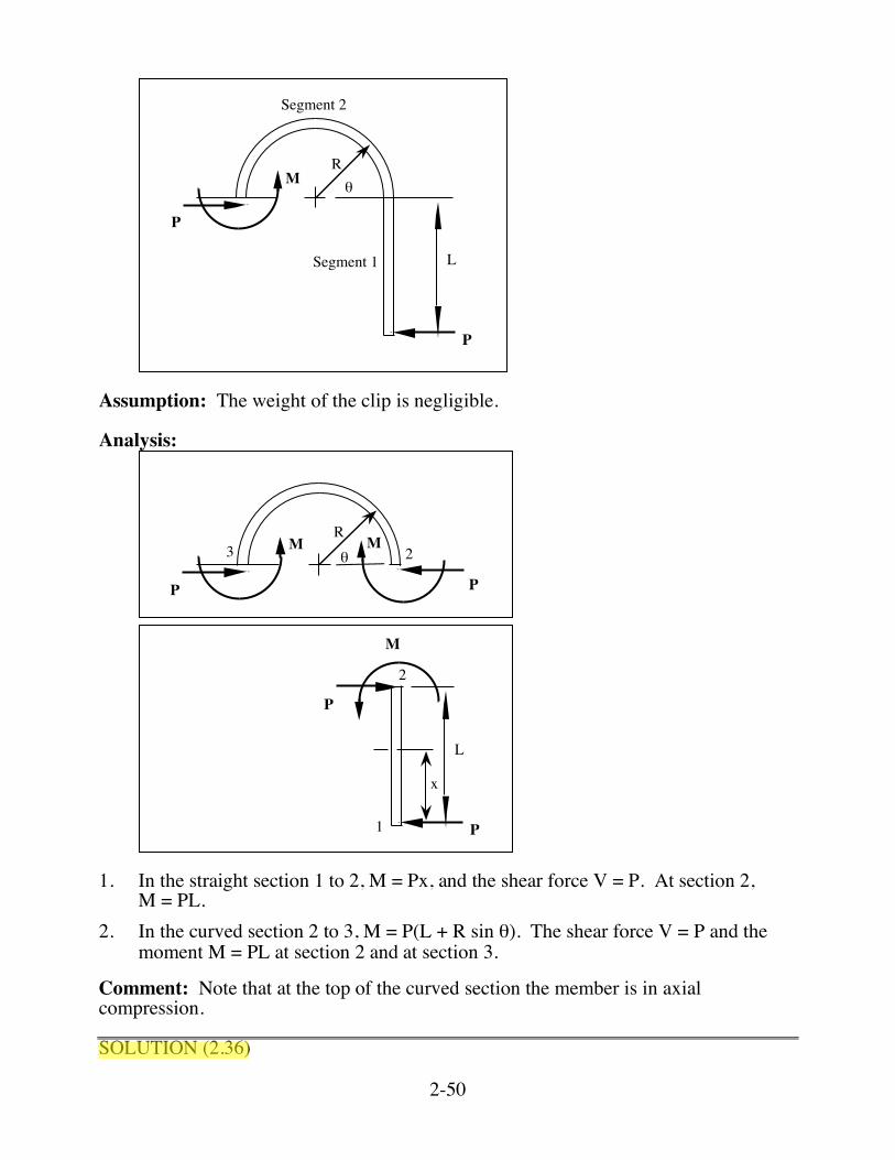
Assumption: The weight of the round bar is negligible. Analysis: 1. For section 1 to 2, M = Px 2. For section 2 to 3, M = P(L cos θ + R sin θ) and T = P[L sin θ + R(1 - cos θ)]. SOLUTION (2.35) Known: The spring clip shown in Fig. P2.35 has a force P acting on the free end. We are to neglect the weight of the clip. Find: Draw free-body diagrams for segments 1 and 2 – straight and curved portions of the clip. Also, determine the force and moments acting on the ends of both segments. Schematic and Given Data:
2-50
!M
P
R
L
P
Segment 1
Segment 2
Assumption: The weight of the clip is negligible. Analysis:
!M
R
P P
M
P
L
P
M
x
3
2
2
1
1. In the straight section 1 to 2, M = Px, and the shear force V = P. At section 2,
M = PL. 2. In the curved section 2 to 3, M = P(L + R sin θ). The shear force V = P and the
moment M = PL at section 2 and at section 3. Comment: Note that at the top of the curved section the member is in axial compression. SOLUTION (2.36)
2-51
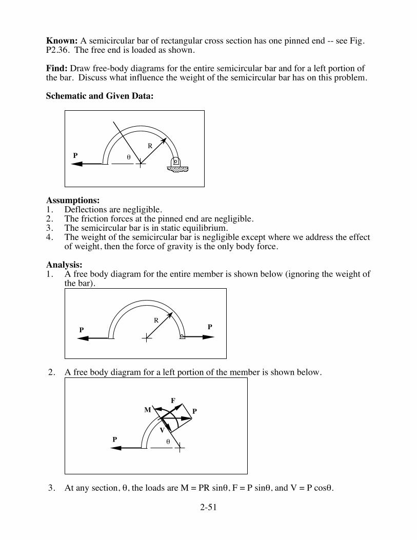
Known: A semicircular bar of rectangular cross section has one pinned end -- see Fig. P2.36. The free end is loaded as shown. Find: Draw free-body diagrams for the entire semicircular bar and for a left portion of the bar. Discuss what influence the weight of the semicircular bar has on this problem. Schematic and Given Data:
P !
R
Assumptions: 1. Deflections are negligible. 2. The friction forces at the pinned end are negligible. 3. The semicircular bar is in static equilibrium. 4. The weight of the semicircular bar is negligible except where we address the effect
of weight, then the force of gravity is the only body force. Analysis: 1. A free body diagram for the entire member is shown below (ignoring the weight of
the bar).
PPR
2. A free body diagram for a left portion of the member is shown below.
M
P !
F
V
P
3. At any section, θ, the loads are M = PR sinθ, F = P sinθ, and V = P cosθ.
2-52
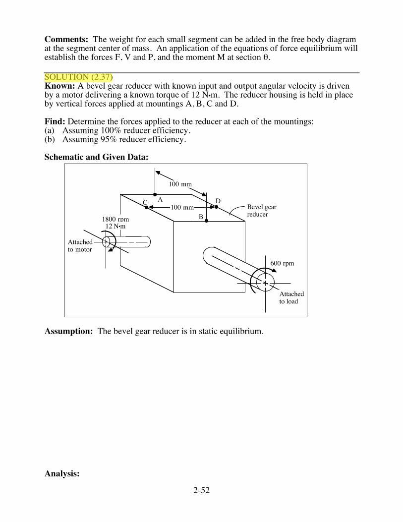
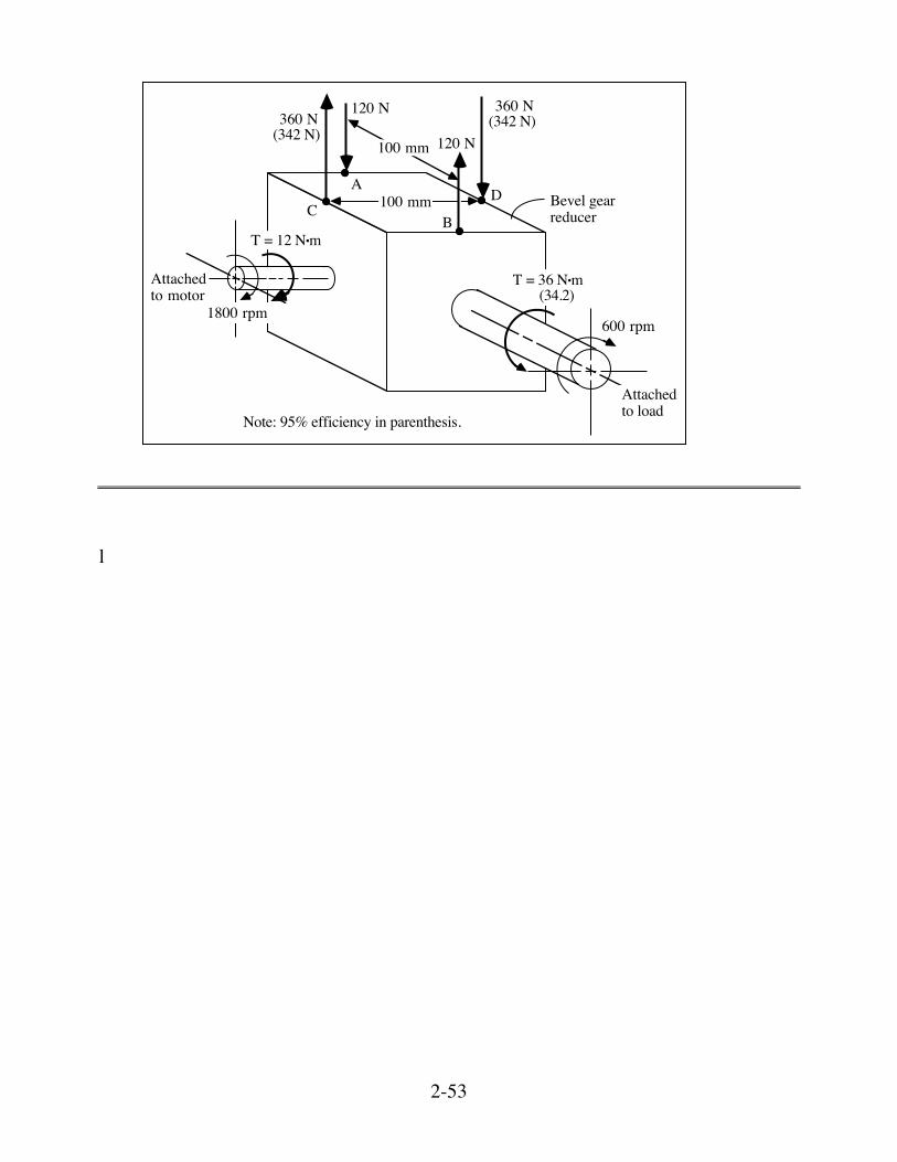
Comments: The weight for each small segment can be added in the free body diagram at the segment center of mass. An application of the equations of force equilibrium will establish the forces F, V and P, and the moment M at section θ. SOLUTION (2.37) Known: A bevel gear reducer with known input and output angular velocity is driven by a motor delivering a known torque of 12 N•m. The reducer housing is held in place by vertical forces applied at mountings A, B, C and D. Find: Determine the forces applied to the reducer at each of the mountings: (a) Assuming 100% reducer efficiency. (b) Assuming 95% reducer efficiency. Schematic and Given Data:
100 mm
100 mm
A
B
C DBevel gearreducer
Attachedto load
600 rpm
1800 rpm
Attached to motor
12 N•m
Assumption: The bevel gear reducer is in static equilibrium. Analysis:
2-53
100 mm
100 mm
A
BC
D Bevel gearreducer
Attachedto load
600 rpm1800 rpm
Attached to motor
T = 36 N•m(34.2)
T = 12 N•m
120 N
120 N
360 N(342 N)360 N
(342 N)
Note: 95% efficiency in parenthesis.
l
2-58
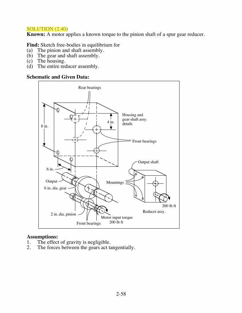
SOLUTION (2.40) Known: A motor applies a known torque to the pinion shaft of a spur gear reducer. Find: Sketch free-bodies in equilibrium for (a) The pinion and shaft assembly. (b) The gear and shaft assembly. (c) The housing. (d) The entire reducer assembly. Schematic and Given Data:
8 in.
Rear bearings
4 in.
Front bearings
6 in.
Output shaft
Mountings
200 lb ftReducer assy.
Motor input torque200 lb ftFront bearings
2 in. dia. pinion
6 in. dia. gearOutput
Housing andgear-shaft assy.details
Assumptions: 1. The effect of gravity is negligible. 2. The forces between the gears act tangentially.
2-59
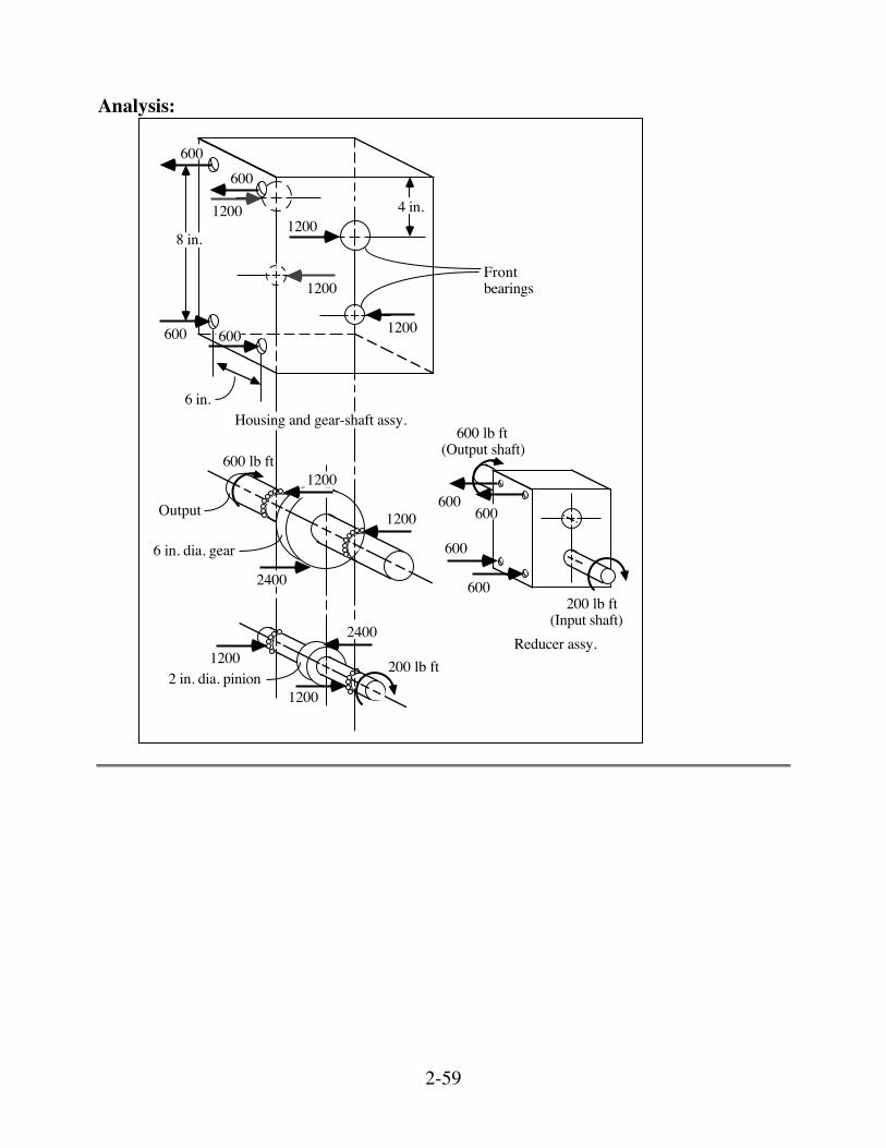
Analysis:
8 in.
4 in.
6 in.
1200
1200
1200
1200
1200
1200
1200
1200
600
600
600
600
600600
600600
2400
2400
600 lb ft
200 lb ft
Output
(Output shaft)600 lb ft
200 lb ft(Input shaft)
6 in. dia. gear
2 in. dia. pinion
Reducer assy.
Housing and gear-shaft assy.
Frontbearings
2-60
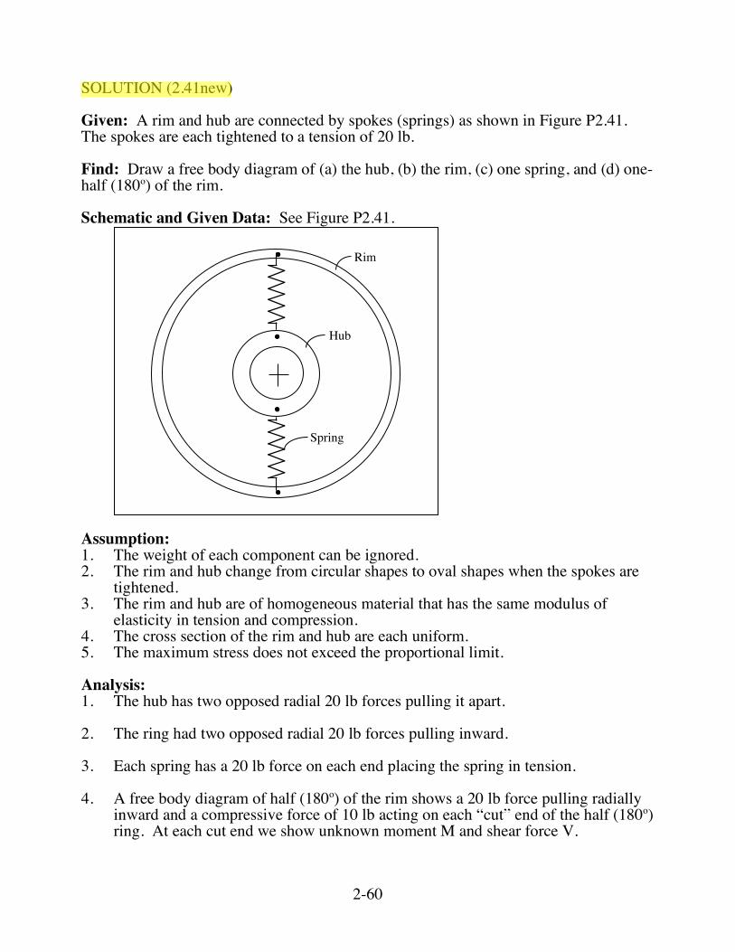
SOLUTION (2.41new) Given: A rim and hub are connected by spokes (springs) as shown in Figure P2.41. The spokes are each tightened to a tension of 20 lb. Find: Draw a free body diagram of (a) the hub, (b) the rim, (c) one spring, and (d) one-half (180o) of the rim. Schematic and Given Data: See Figure P2.41.
F
Hub
Rim
Spring
Assumption: 1. The weight of each component can be ignored. 2. The rim and hub change from circular shapes to oval shapes when the spokes are
tightened. 3. The rim and hub are of homogeneous material that has the same modulus of
elasticity in tension and compression. 4. The cross section of the rim and hub are each uniform. 5. The maximum stress does not exceed the proportional limit. Analysis: 1. The hub has two opposed radial 20 lb forces pulling it apart. 2. The ring had two opposed radial 20 lb forces pulling inward. 3. Each spring has a 20 lb force on each end placing the spring in tension. 4. A free body diagram of half (180o) of the rim shows a 20 lb force pulling radially
inward and a compressive force of 10 lb acting on each “cut” end of the half (180o) ring. At each cut end we show unknown moment M and shear force V.
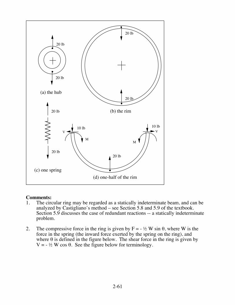
2-61
(a) the hub
20 lb
20 lb
(b) the rim
20 lb
20 lb
(c) one spring(d) one-half of the rim
20 lb
20 lb20 lb
10 lb 10 lb
MM
V V
Comments: 1. The circular ring may be regarded as a statically indeterminate beam, and can be
analyzed by Castigliano’s method – see Section 5.8 and 5.9 of the textbook. Section 5.9 discusses the case of redundant reactions -- a statically indeterminate problem.
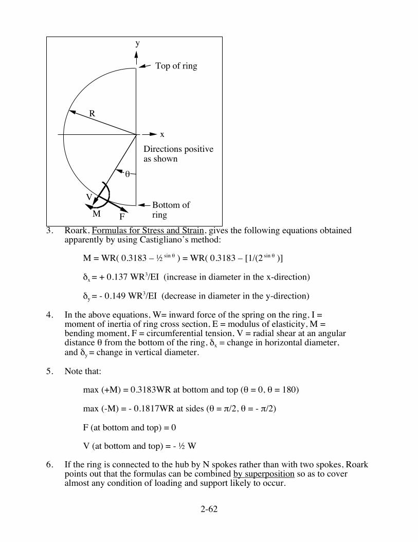
2. The compressive force in the ring is given by F = - ½ W sin θ, where W is the
force in the spring (the inward force exerted by the spring on the ring), and where θ is defined in the figure below. The shear force in the ring is given by V = - ½ W cos θ. See the figure below for terminology.
2-62
!
V
M
Top of ring
F
R
x
y
Directions positive as shown
Bottom of ring
3. Roark, Formulas for Stress and Strain, gives the following equations obtained
apparently by using Castigliano’s method:
M = WR( 0.3183 – ½ sin θ ) = WR( 0.3183 – [1/(2 sin θ )]
δx = + 0.137 WR3/EI (increase in diameter in the x-direction)
δy = - 0.149 WR3/EI (decrease in diameter in the y-direction) 4. In the above equations, W= inward force of the spring on the ring, I =
moment of inertia of ring cross section, E = modulus of elasticity, M = bending moment, F = circumferential tension, V = radial shear at an angular distance θ from the bottom of the ring, δx = change in horizontal diameter, and δy = change in vertical diameter.
5. Note that:
max (+M) = 0.3183WR at bottom and top (θ = 0, θ = 180)
max (-M) = - 0.1817WR at sides (θ = π/2, θ = - π/2)
F (at bottom and top) = 0
V (at bottom and top) = - ½ W 6. If the ring is connected to the hub by N spokes rather than with two spokes, Roark
points out that the formulas can be combined by superposition so as to cover almost any condition of loading and support likely to occur.

2-63
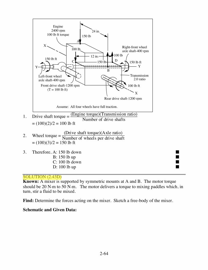
SOLUTION SOLUTION (2.42) Known: An engine rotates with a known angular velocity and delivers a known torque to a transmission which drives a front and rear axle. Find: Determine the forces applied to the free-body at A, B, C, and D. Schematic and Given Data:
X
Y Y
12 in.
24 in.
Engine2400 rpm
100 lb ft torque
A
B
C D
Rear drive shaft-1200 rpm
Front drive shaft-1200 rpm
Rear axle(not part offree-body)
X
Transmission2.0 ratio
Left-front wheel axle shaft-400 rpm
Right-front wheelaxle shaft-400 rpm
Assumptions: 1. The friction and gravity forces are negligible. 2. The mountings exert only vertical forces. 3. All four wheels have full traction. Analysis:
2-64
X
Y Y
12 in.
24 in.Engine
2400 rpm100 lb ft torque
A
B
C D
Rear drive shaft-1200 rpm
Front drive shaft-1200 rpm
Transmission2.0 ratio
Left-front wheel axle shaft-400 rpm
Right-front wheelaxle shaft-400 rpm
X(T = 100 lb ft)
100 lb ft
150 lb ft
100 lb
100 lb
150 lb
150 lb150 lb ft
Assume: All four wheels have full traction.
1. Drive shaft torque = (Engine torque)(Transmission ratio)Number of drive shafts
= (100)(2)/2 = 100 lb ft 2. Wheel torque = (Drive shaft torque)(Axle ratio)Number of wheels per drive shaft = (100)(3)/2 = 150 lb ft 3. Therefore, A: 150 lb down ■ B: 150 lb up ■ C: 100 lb down ■ D: 100 lb up ■ SOLUTION (2.43D) Known: A mixer is supported by symmetric mounts at A and B. The motor torque should be 20 N.m to 50 N.m. The motor delivers a torque to mixing paddles which, in turn, stir a fluid to be mixed. Find: Determine the forces acting on the mixer. Sketch a free-body of the mixer. Schematic and Given Data:

2-65
A BMotor
Directionof rotation
200 mm
g
Mass of mixersystem = 50 kg
The motor delivers a torque of20 Nm to 50 Nm to the mixerblades.
x
yz
Decision: A motor with a maximum torque output of 50 N•m is selected for analysis. Assumption: The fluid forces on the paddles create a torque to oppose the rotation of the paddles. Other fluid forces can be neglected (e.g. the paddles are buoyed up by the weight of the displaced fluid). Analysis: 1. The torque exerted on the paddles by the fluid is 50 N•m maximum. 2. Mounting forces to resist torque = (50 N•m)/(0.2 m) = 250 N. Thus, a force of 250
N is exerted at A and at B. 3. Gravitational forces apply F = ma = (50 kg)(9.8 m/s2) = 490 N. Thus, there is a
245 N force upward at A and at B. 4. The forces are shown on the free body diagram for the maximum motor torque of
50 N•m.
A B
Directionof rotation
200 mm
g
Mass of mixersystem = 50 kg
245 N 245 N
250 N
250 N
490 N
2-66
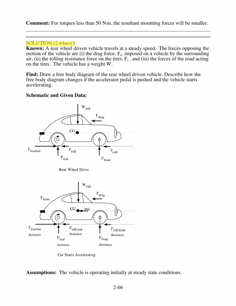
Comment: For torques less than 50 N•m, the resultant mounting forces will be smaller. SOLUTION (2.44new) Known: A rear wheel driven vehicle travels at a steady speed. The forces opposing the motion of the vehicle are (i) the drag force, Fd, imposed on a vehicle by the surrounding air, (ii) the rolling resistance force on the tires, Fr , and (iii) the forces of the road acting on the tires. The vehicle has a weight W. Find: Draw a free body diagram of the rear wheel driven vehicle. Describe how the free body diagram changes if the accelerator pedal is pushed and the vehicle starts accelerating. Schematic and Given Data:
Assumptions: The vehicle is operating initially at steady state conditions.
2-67
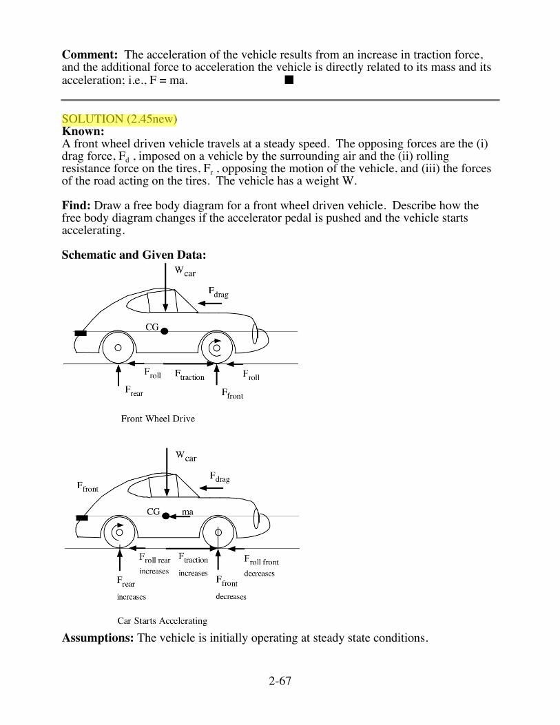
Comment: The acceleration of the vehicle results from an increase in traction force, and the additional force to acceleration the vehicle is directly related to its mass and its acceleration; i.e., F = ma. ■ SOLUTION (2.45new) Known: A front wheel driven vehicle travels at a steady speed. The opposing forces are the (i) drag force, Fd , imposed on a vehicle by the surrounding air and the (ii) rolling resistance force on the tires, Fr , opposing the motion of the vehicle, and (iii) the forces of the road acting on the tires. The vehicle has a weight W. Find: Draw a free body diagram for a front wheel driven vehicle. Describe how the free body diagram changes if the accelerator pedal is pushed and the vehicle starts accelerating. Schematic and Given Data:
Assumptions: The vehicle is initially operating at steady state conditions.
2-68
Comment: Free body diagrams are shown above. Although the front tire force(s) decreases with acceleration, this is only a traction problem if the front wheel(s) loses a grip on the road. ■
2-73
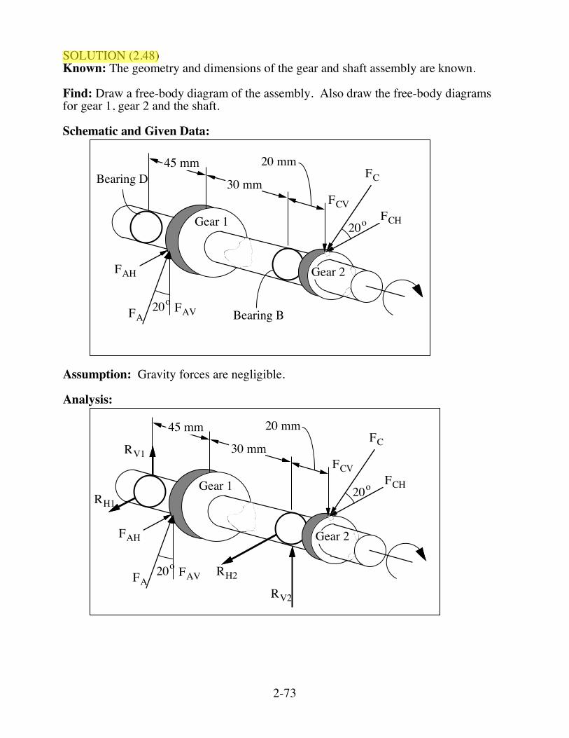
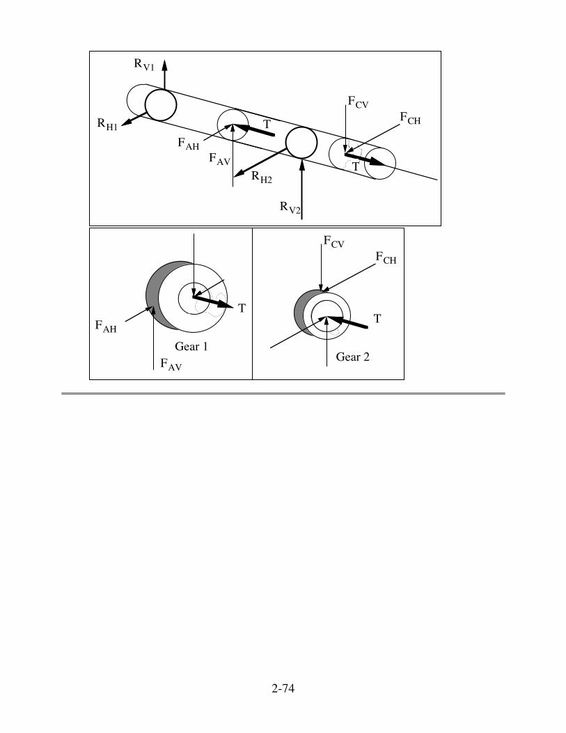
SOLUTION (2.48) Known: The geometry and dimensions of the gear and shaft assembly are known. Find: Draw a free-body diagram of the assembly. Also draw the free-body diagrams for gear 1, gear 2 and the shaft. Schematic and Given Data:
FAV
FAH
FA
FCVFCH
FC45 mm
30 mm
20 mm
Gear 1
Gear 2
20o
20oBearing B
Bearing D
Assumption: Gravity forces are negligible. Analysis:
FAV
FAH
FA
FCVFCH
FCRV1
RV2
RH2
RH1
45 mm
30 mm
20 mm
Gear 1
Gear 2
20o
20o
2-74
FAVFAH
FCVFCH
RV1
RV2
RH2
RH1 T
T
Gear 1FAV
FAH
T
Gear 2
FCVFCH
T
2-75
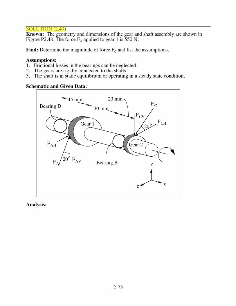
SOLUTION (2.49) Known: The geometry and dimensions of the gear and shaft assembly are shown in Figure P2.48. The force FA applied to gear 1 is 550 N. Find: Determine the magnitude of force FC and list the assumptions. Assumptions: 1. Frictional losses in the bearings can be neglected. 2. The gears are rigidly connected to the shafts. 3. The shaft is in static equilibrium or operating in a steady state condition. Schematic and Given Data:
X
Y
Z
FAV
FAH
FA
FCVFCH
FC45 mm
30 mm
20 mm
Gear 1
Gear 2
20o
20oBearing B
Bearing D
Analysis:
2-76
X
Y
Z
FAV
FAH
FA
FCVFCH
FC45 mm
30 mm
20 mm
Gear 1
Gear 2
20o
20oBearing B
Bearing D
, dia = 24 mm
= 550 N
, dia = 50 mm
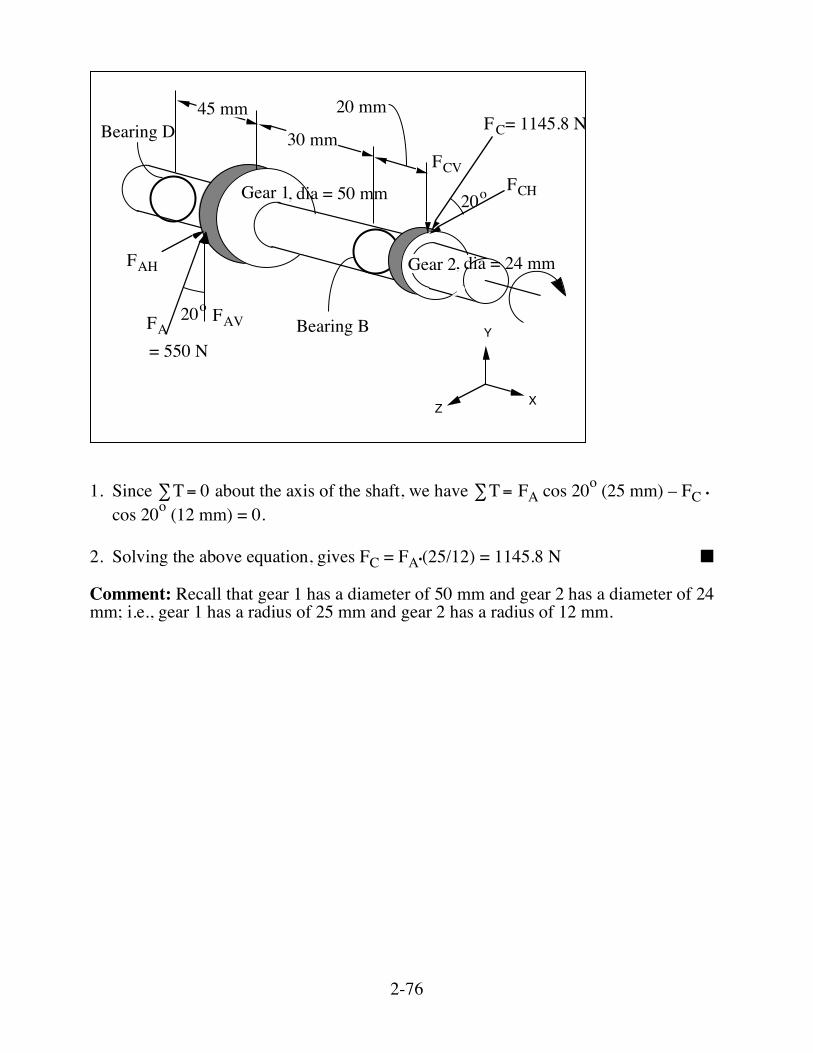
= 1145.8 N
1. Since
!
T= 0" about the axis of the shaft, we have
!
T=" FA cos 20o (25 mm) – FC •
cos 20o (12 mm) = 0. 2. Solving the above equation, gives FC = FA•(25/12) = 1145.8 N ■ Comment: Recall that gear 1 has a diameter of 50 mm and gear 2 has a diameter of 24 mm; i.e., gear 1 has a radius of 25 mm and gear 2 has a radius of 12 mm.
2-77
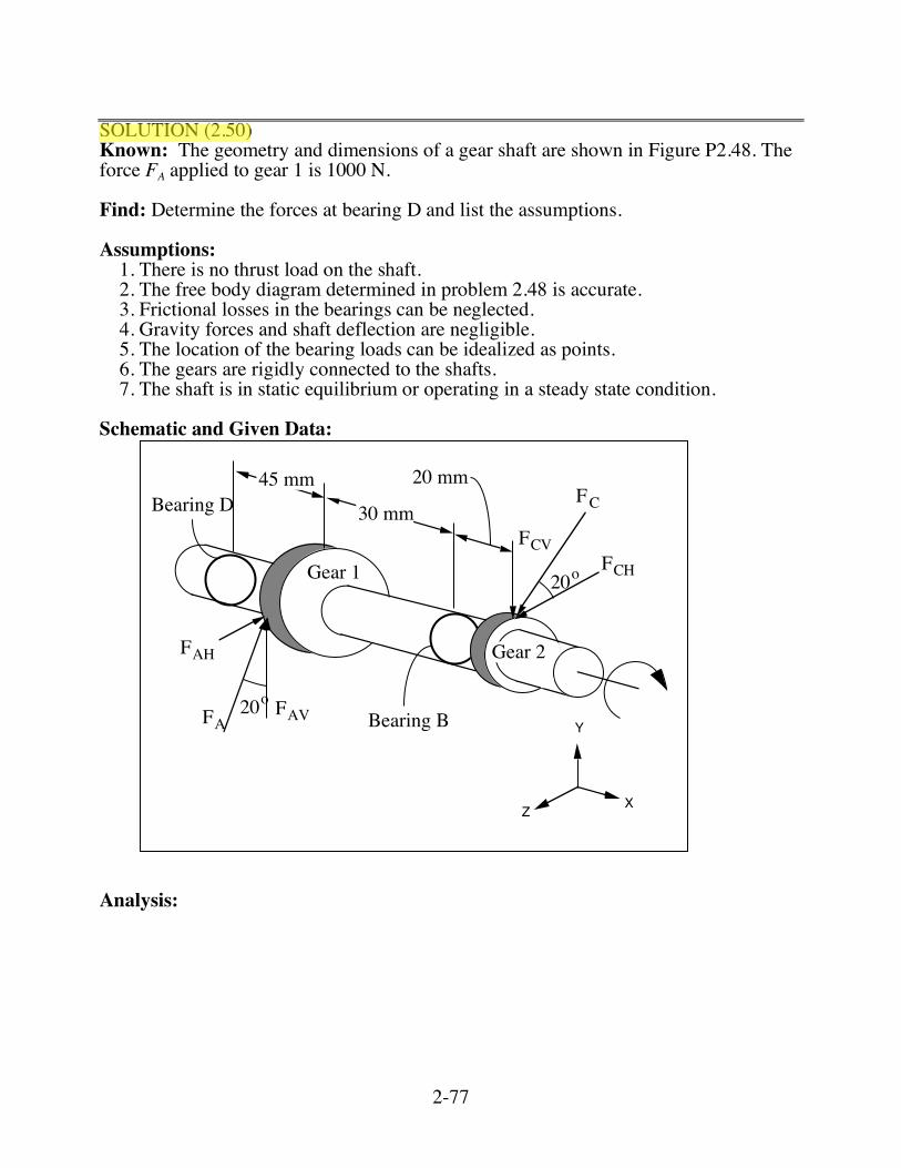
SOLUTION (2.50) Known: The geometry and dimensions of a gear shaft are shown in Figure P2.48. The force FA applied to gear 1 is 1000 N. Find: Determine the forces at bearing D and list the assumptions. Assumptions:
1. There is no thrust load on the shaft. 2. The free body diagram determined in problem 2.48 is accurate. 3. Frictional losses in the bearings can be neglected. 4. Gravity forces and shaft deflection are negligible. 5. The location of the bearing loads can be idealized as points. 6. The gears are rigidly connected to the shafts. 7. The shaft is in static equilibrium or operating in a steady state condition.
Schematic and Given Data:
X
Y
Z
FAV
FAH
FA
FCVFCH
FC45 mm
30 mm
20 mm
Gear 1
Gear 2
20o
20oBearing B
Bearing D
Analysis:
2-78
X
Y
Z
FAV
FAH
FA
FCVFCH
FC45 mm
30 mm
20 mm
Gear 1
Gear 2
20o
20oBearing B
Bearing D
, dia = 24 mm
= 1000 N
, dia = 50 mm
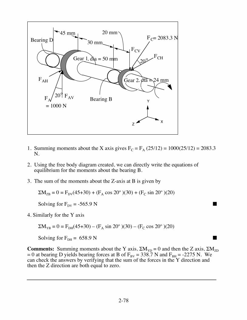
= 2083.3 N
1. Summing moments about the X axis gives FC = FA (25/12) = 1000(25/12) = 2083.3
N. 2. Using the free body diagram created, we can directly write the equations of
equilibrium for the moments about the bearing B. 3. The sum of the moments about the Z-axis at B is given by
ΣMZB = 0 = FDV(45+30) + (FA cos 20o )(30) + (FC sin 20o )(20)
Solving for FDV = -565.9 N ■ 4. Similarly for the Y axis
ΣMYB = 0 = FDH(45+30) – (FA sin 20o )(30) – (FC cos 20o )(20)
Solving for FDH = 658.9 N ■ Comments: Summing moments about the Y axis, ΣMYD = 0 and then the Z axis, ΣMZD = 0 at bearing D yields bearing forces at B of FBV = 338.7 N and FBH = -2275 N. We can check the answers by verifying that the sum of the forces in the Y direction and then the Z direction are both equal to zero.
2-79
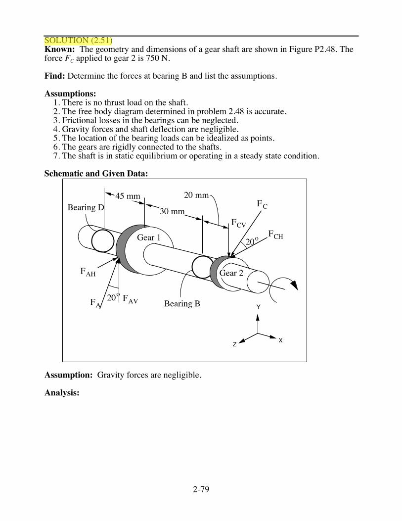
SOLUTION (2.51) Known: The geometry and dimensions of a gear shaft are shown in Figure P2.48. The force FC applied to gear 2 is 750 N. Find: Determine the forces at bearing B and list the assumptions. Assumptions:
1. There is no thrust load on the shaft. 2. The free body diagram determined in problem 2.48 is accurate. 3. Frictional losses in the bearings can be neglected. 4. Gravity forces and shaft deflection are negligible. 5. The location of the bearing loads can be idealized as points. 6. The gears are rigidly connected to the shafts. 7. The shaft is in static equilibrium or operating in a steady state condition.
Schematic and Given Data:
X
Y
Z
FAV
FAH
FA
FCVFCH
FC45 mm
30 mm
20 mm
Gear 1
Gear 2
20o
20oBearing B
Bearing D
Assumption: Gravity forces are negligible. Analysis:
2-80
X
Y
Z
FAV
FAH
FA
FCVFCH
FC45 mm
30 mm
20 mm
Gear 1
Gear 2
20o
20oBearing B
Bearing D
, dia = 24 mm
= 360 N
, dia = 50 mm
= 750 N
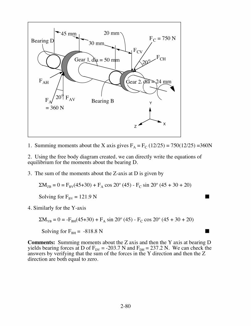
1. Summing moments about the X axis gives FA = FC (12/25) = 750(12/25) =360N 2. Using the free body diagram created, we can directly write the equations of equilibrium for the moments about the bearing D. 3. The sum of the moments about the Z-axis at D is given by
ΣMZB = 0 = FBV(45+30) + FA cos 20o (45) - FC sin 20o (45 + 30 + 20)
Solving for FBV = 121.9 N ■
4. Similarly for the Y-axis
ΣMYB = 0 = -FBH(45+30) + FA sin 20o (45) - FC cos 20o (45 + 30 + 20)
Solving for FBH = -818.8 N ■
Comments: Summing moments about the Z axis and then the Y axis at bearing D yields bearing forces at D of FDV = -203.7 N and FDH = 237.2 N. We can check the answers by verifying that the sum of the forces in the Y direction and then the Z direction are both equal to zero.
2-81
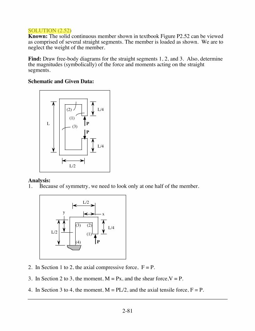
SOLUTION (2.52) Known: The solid continuous member shown in textbook Figure P2.52 can be viewed as comprised of several straight segments. The member is loaded as shown. We are to neglect the weight of the member. Find: Draw free-body diagrams for the straight segments 1, 2, and 3. Also, determine the magnitudes (symbolically) of the force and moments acting on the straight segments. Schematic and Given Data:
(1)
L/4
L/2
L
(2)
(3)P
L/4
P
Analysis: 1. Because of symmetry, we need to look only at one half of the member.
(1)
x
(2)(3) L/4
P
L/2
y
L/2
(4)
2. In Section 1 to 2, the axial compressive force, F = P. 3. In Section 2 to 3, the moment, M = Px, and the shear force,V = P. 4. In Section 3 to 4, the moment, M = PL/2, and the axial tensile force, F = P.
2-82
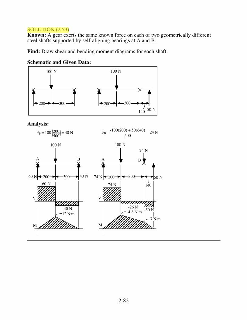
SOLUTION (2.53) Known: A gear exerts the same known force on each of two geometrically different steel shafts supported by self-aligning bearings at A and B. Find: Draw shear and bending moment diagrams for each shaft. Schematic and Given Data:
200 300
140
300200
100 N 100 N
50 N
Analysis:
200 300
140
300200
100 N 100 N
50 N
V
M
V
M
24 N
74 N40 N60 N
60 N
-40 N
74 N
-26 N -50 N12 N•m 14.8 N•m
7 N•m
FB = 100 200500
= 40 N FB = -100(200) + 50(640)500
= 24 N
A BAB
2-83
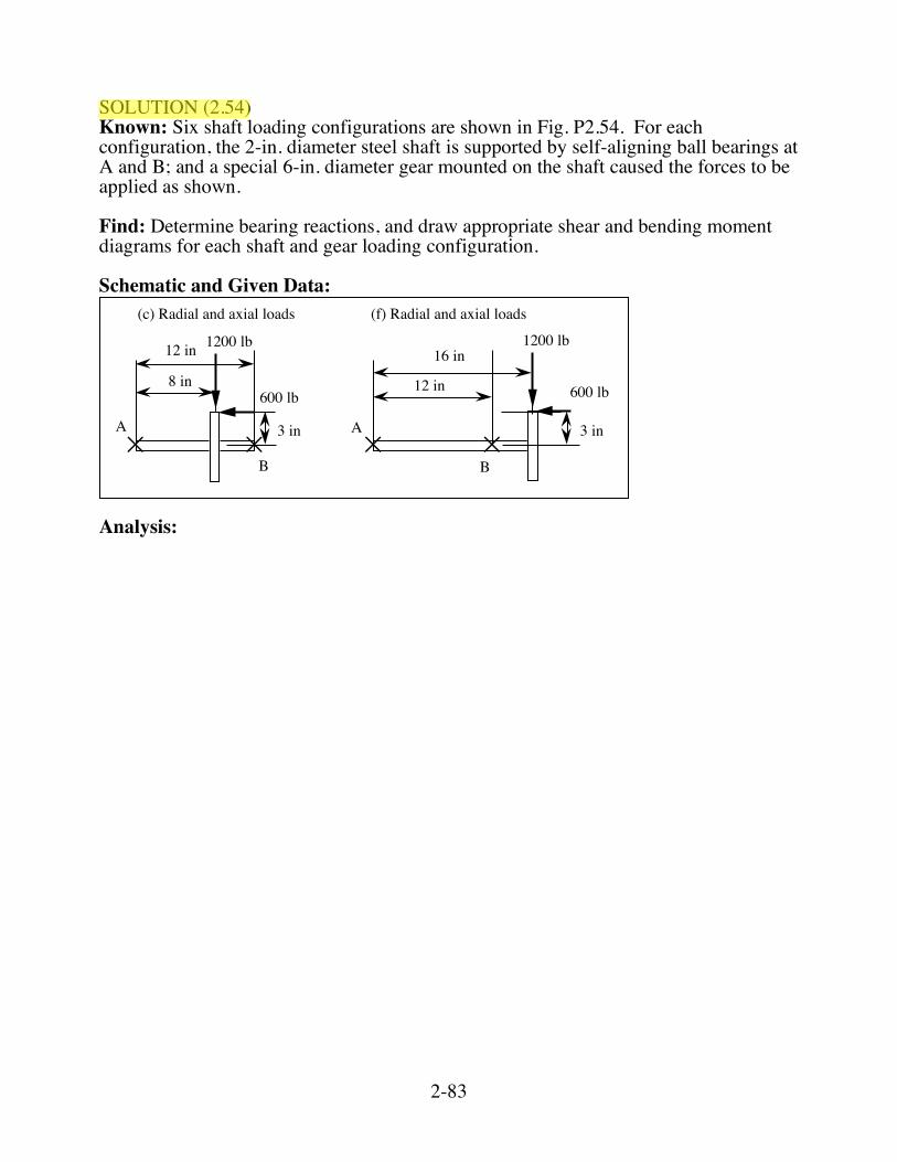
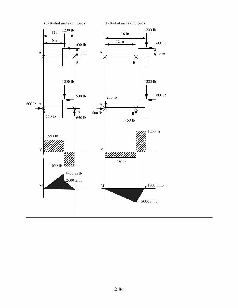
SOLUTION (2.54) Known: Six shaft loading configurations are shown in Fig. P2.54. For each configuration, the 2-in. diameter steel shaft is supported by self-aligning ball bearings at A and B; and a special 6-in. diameter gear mounted on the shaft caused the forces to be applied as shown. Find: Determine bearing reactions, and draw appropriate shear and bending moment diagrams for each shaft and gear loading configuration. Schematic and Given Data:
8 in
A
B
A
B
12 in
12 in
16 in
3 in 3 in
(c) Radial and axial loads (f) Radial and axial loads
600 lb
1200 lb
600 lb
1200 lb
Analysis:
2-84
(c) Radial and axial loads (f) Radial and axial loads
8 in
A
B
12 in
3 in
600 lb
1200 lb
A
B
12 in
16 in
3 in
600 lb
1200 lb
250 lbA
B
600 lb
1200 lb
600 lb
550 lb 650 lb
A
B
600 lb
1200 lb
600 lb
550 lb1200 lb
V V
- 250 lb-650 lb
1450 lb
M M
4400 in lb
2600 in lb1800 in lb
-3000 in lb
2-85
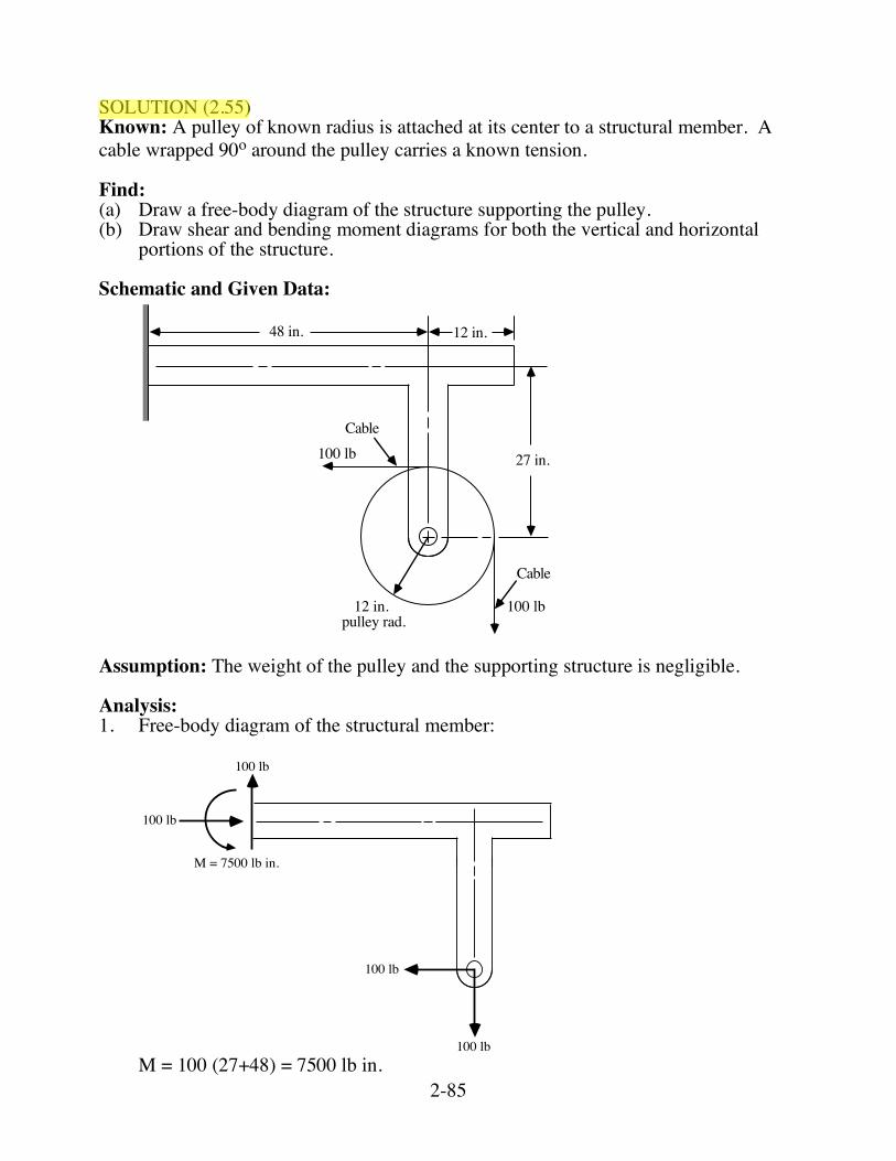
SOLUTION (2.55) Known: A pulley of known radius is attached at its center to a structural member. A cable wrapped 90o around the pulley carries a known tension. Find: (a) Draw a free-body diagram of the structure supporting the pulley. (b) Draw shear and bending moment diagrams for both the vertical and horizontal
portions of the structure. Schematic and Given Data:
12 in.48 in.
27 in.100 lb
100 lb12 in.
Cable
Cable
pulley rad. Assumption: The weight of the pulley and the supporting structure is negligible. Analysis: 1. Free-body diagram of the structural member:
M = 7500 lb in.
100 lb
100 lb
100 lb
100 lb
M = 100 (27+48) = 7500 lb in.
2-86
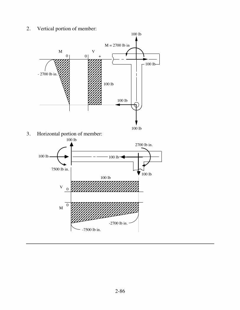
2. Vertical portion of member:
100 lb
100 lb
100 lb
100 lb
100 lb
- 2700 lb in.
00M V
+
M = 2700 lb in
3. Horizontal portion of member:
7500 lb in.100 lb
100 lb
100 lb
100 lb
2700 lb in.
100 lb
-7500 lb in.-2700 lb in.
0
0
V
M
2-87
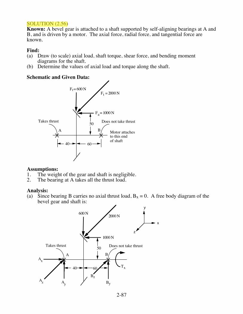
SOLUTION (2.56) Known: A bevel gear is attached to a shaft supported by self-aligning bearings at A and B, and is driven by a motor. The axial force, radial force, and tangential force are known. Find: (a) Draw (to scale) axial load, shaft torque, shear force, and bending moment
diagrams for the shaft. (b) Determine the values of axial load and torque along the shaft. Schematic and Given Data:
40 60
A B
Takes thrust Does not take thrust
Motor attaches to this end of shaft
50
Fa = 1000 N
Fr= 600 NFt = 2000 N
Assumptions: 1. The weight of the gear and shaft is negligible. 2. The bearing at A takes all the thrust load. Analysis: (a) Since bearing B carries no axial thrust load, Bx = 0. A free body diagram of the
bevel gear and shaft is:
40 60
A B
Takes thrust Does not take thrust50
1000 N
600 N 2000 N
y
x
z
Tx
BzBy
xA
zAyA
2-88
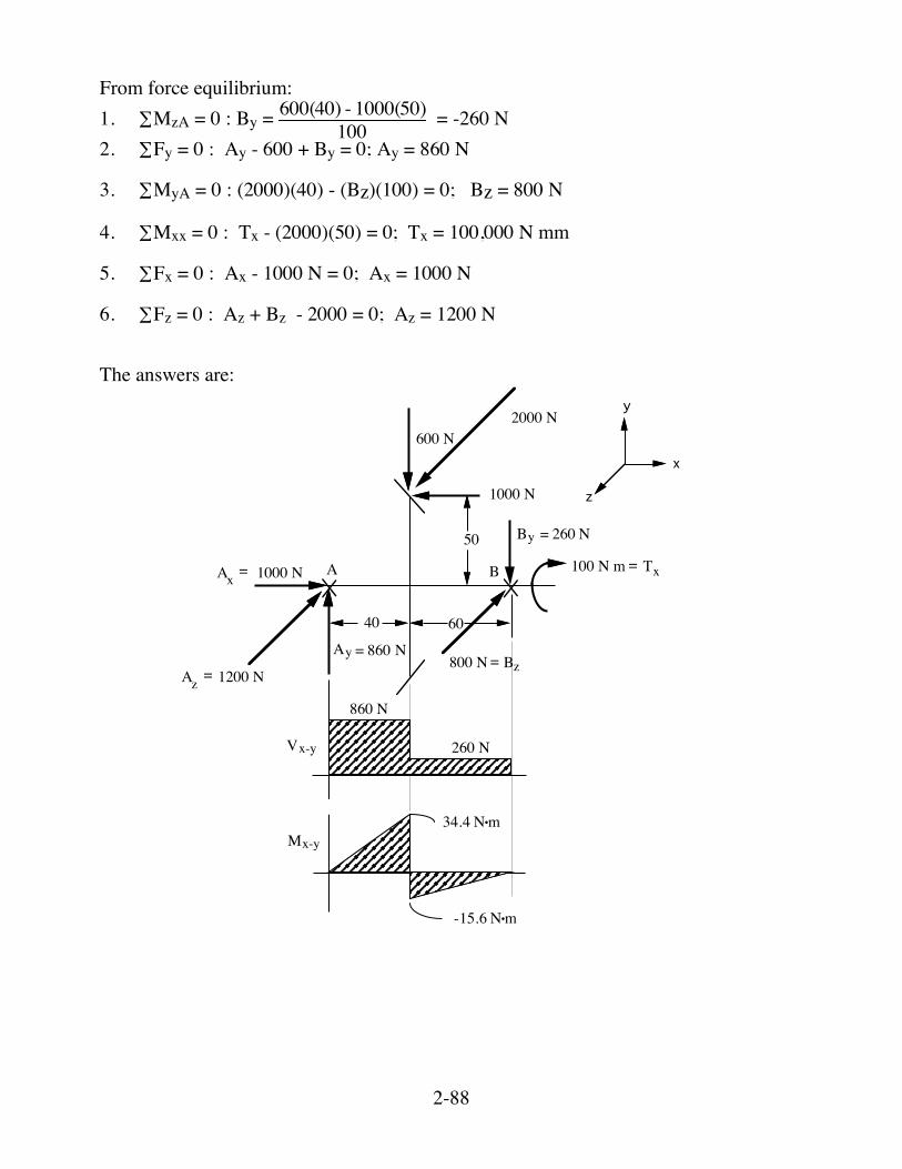
From force equilibrium: 1. ∑MzA = 0 : By = 600(40) - 1000(50)100 = -260 N 2. ∑Fy = 0 : Ay - 600 + By = 0; Ay = 860 N 3. ∑MyA = 0 : (2000)(40) - (Bz)(100) = 0; Bz = 800 N 4. ∑Mxx = 0 : Tx - (2000)(50) = 0; Tx = 100,000 N mm 5. ∑Fx = 0 : Ax - 1000 N = 0; Ax = 1000 N 6. ∑Fz = 0 : Az + Bz - 2000 = 0; Az = 1200 N The answers are:
40 60
A B
50
600 N
1000 N
1000 N
860 N
260 N
34.4 N•m
-15.6 N•m
2000 N
N = 860 Ay
= 260 NBy
1200 N800 N
100 N m
Vx-y
Mx-y
y
x
z
Tx
Bz
xA
zA=
=
= =
2-89
48.0 N•m
1200 N
800 N
Vx-z
Mx-z
1000 N
100 N mTxx
Fx
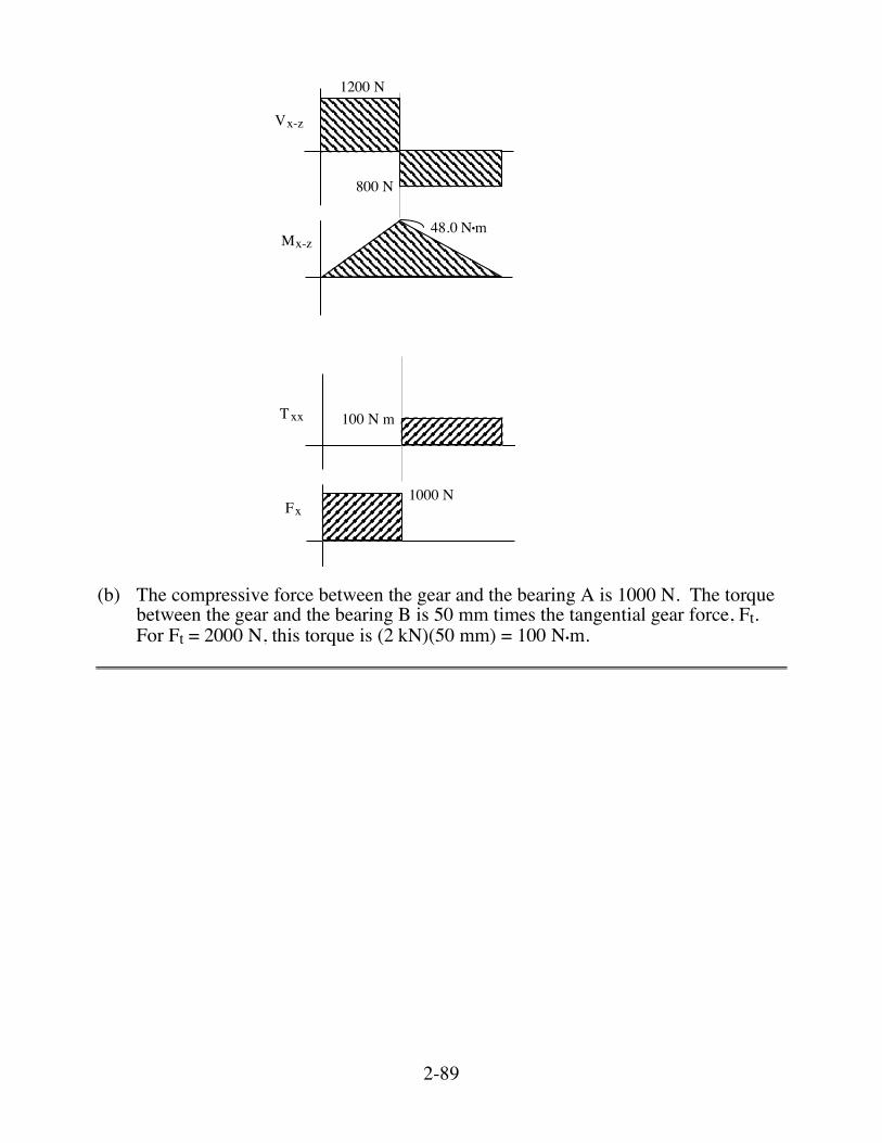
(b) The compressive force between the gear and the bearing A is 1000 N. The torque
between the gear and the bearing B is 50 mm times the tangential gear force, Ft. For Ft = 2000 N, this torque is (2 kN)(50 mm) = 100 N•m.
2-90
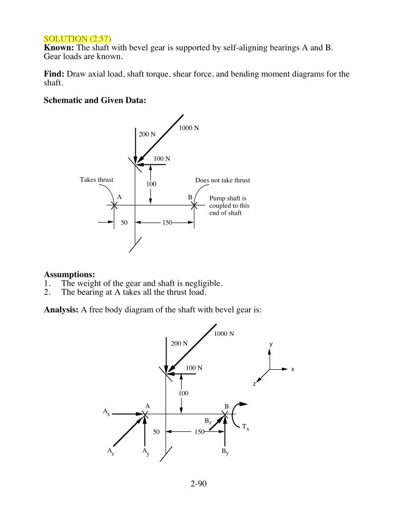
SOLUTION (2.57) Known: The shaft with bevel gear is supported by self-aligning bearings A and B. Gear loads are known. Find: Draw axial load, shaft torque, shear force, and bending moment diagrams for the shaft. Schematic and Given Data:
A B
Takes thrust Does not take thrust
Pump shaft iscoupled to thisend of shaft
200 N
100 N
50 150
100
1000 N
Assumptions: 1. The weight of the gear and shaft is negligible. 2. The bearing at A takes all the thrust load. Analysis: A free body diagram of the shaft with bevel gear is:
A B
200 N
100 N
50 150
100
1000 N
Bz
By
xA
zA yA
Tx
y
x
z
2-91
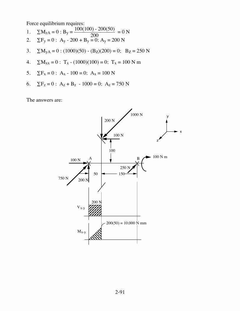
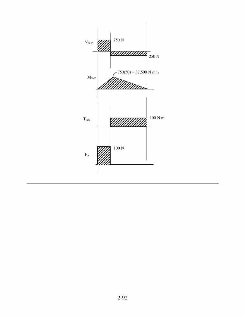
Force equilibrium requires: 1. ∑MzA = 0 : By = 100(100) - 200(50)200 = 0 N 2. ∑Fy = 0 : Ay - 200 + By = 0; Ay = 200 N 3. ∑MyA = 0 : (1000)(50) - (Bz)(200) = 0; Bz = 250 N 4. ∑Mxx = 0 : Tx - (1000)(100) = 0; Tx = 100 N m 5. ∑Fx = 0 : Ax - 100 = 0; Ax = 100 N 6. ∑Fz = 0 : Az + Bz - 1000 = 0; Az = 750 N The answers are:
A B
200 N
100 N
50 150
100
100 N
200 N
1000 N
750 N
250 N
100 N m
200 N
200(50) = 10,000 N mm
Vx-y
Mx-y
y
x
z
2-92
750 N
750(50) = 37,500 N mmMx-z
Vx-z
250 N
100 N m
100 N
Txx
Fx
2-93
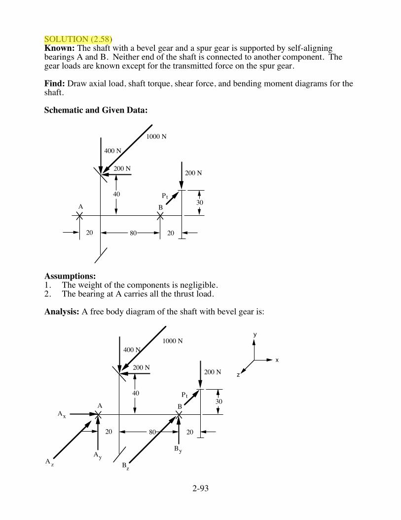
SOLUTION (2.58) Known: The shaft with a bevel gear and a spur gear is supported by self-aligning bearings A and B. Neither end of the shaft is connected to another component. The gear loads are known except for the transmitted force on the spur gear. Find: Draw axial load, shaft torque, shear force, and bending moment diagrams for the shaft. Schematic and Given Data:
A B30
40
8020 20
200 N
400 N
200 N
1000 N
Pt
Assumptions: 1. The weight of the components is negligible. 2. The bearing at A carries all the thrust load. Analysis: A free body diagram of the shaft with bevel gear is:
A B30
40
8020 20
200 N
400 N
200 N
1000 N
Pt
y
x
z
xA
yByA
zA Bz
2-94
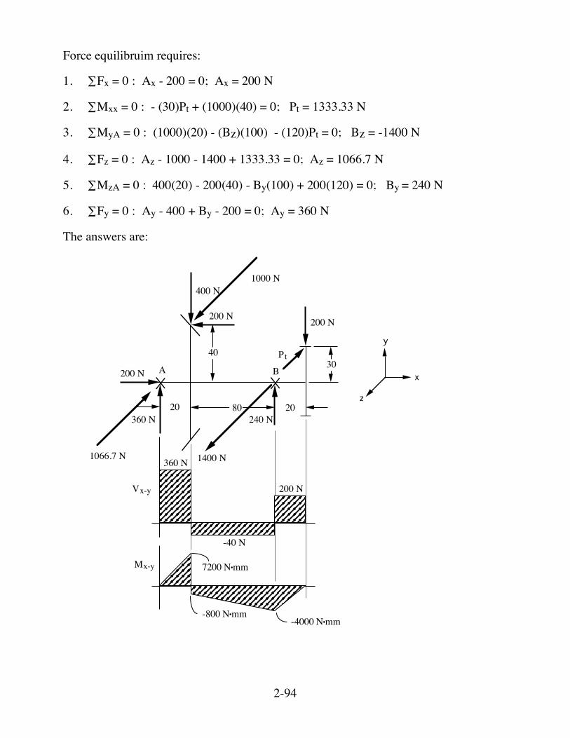
Force equilibruim requires: 1. ∑Fx = 0 : Ax - 200 = 0; Ax = 200 N 2. ∑Mxx = 0 : - (30)Pt + (1000)(40) = 0; Pt = 1333.33 N 3. ∑MyA = 0 : (1000)(20) - (Bz)(100) - (120)Pt = 0; Bz = -1400 N 4. ∑Fz = 0 : Az - 1000 - 1400 + 1333.33 = 0; Az = 1066.7 N 5. ∑MzA = 0 : 400(20) - 200(40) - By(100) + 200(120) = 0; By = 240 N 6. ∑Fy = 0 : Ay - 400 + By - 200 = 0; Ay = 360 N The answers are:
A B30
40
8020 20
200 N
400 N
200 N
200 N
360 N 240 N
360 N
-40 N
200 N
7200 N•mm
-4000 N•mm-800 N•mm
1000 N
Pt
1066.7 N 1400 N
y
x
z
Vx-y
Mx-y
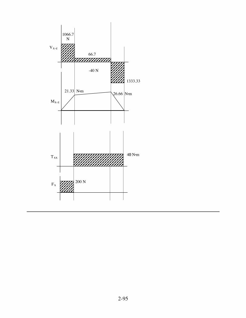
2-95
-40 N
1066.7 ! N
Vx-z
Mx-z
66.7
1333.33
N•m21.33 26.66 N•m
66.7 N400 N•mTxx
200 NFx
2-96
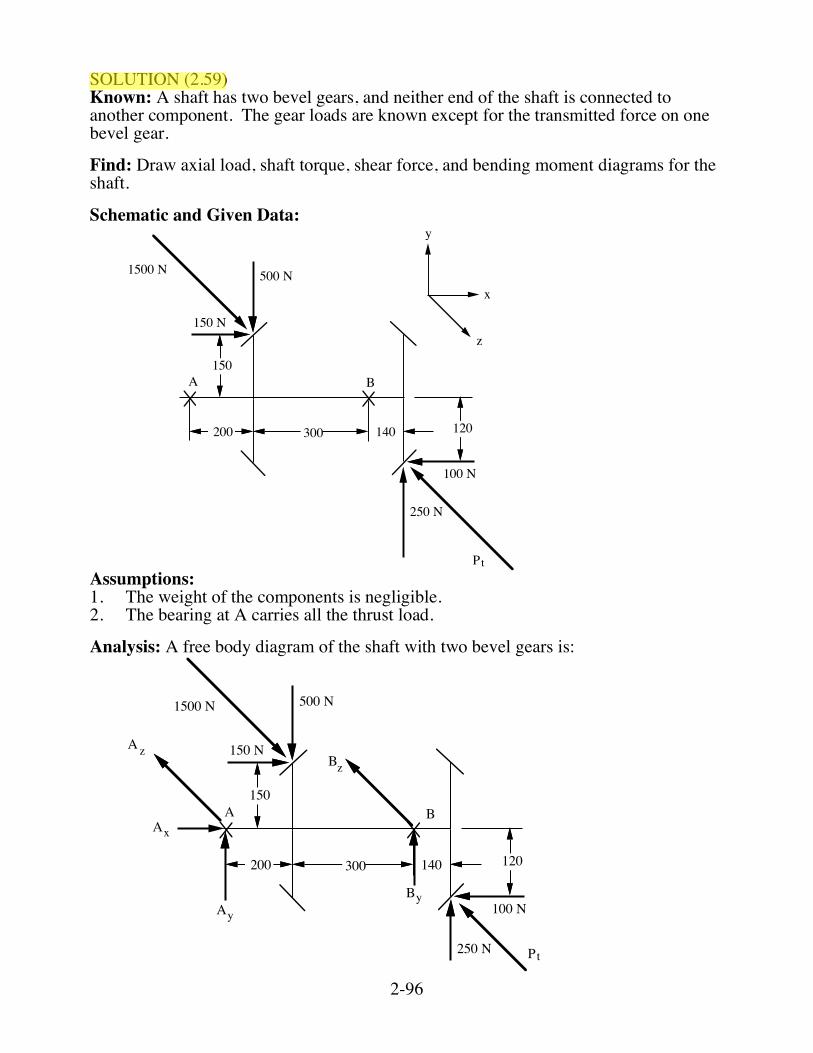
SOLUTION (2.59) Known: A shaft has two bevel gears, and neither end of the shaft is connected to another component. The gear loads are known except for the transmitted force on one bevel gear. Find: Draw axial load, shaft torque, shear force, and bending moment diagrams for the shaft. Schematic and Given Data:
A B
250 N
100 N
120140300200
150
500 N
150 N
1500 N
Pt
y
x
z
Assumptions: 1. The weight of the components is negligible. 2. The bearing at A carries all the thrust load. Analysis: A free body diagram of the shaft with two bevel gears is:
A B
250 N
100 N
120140300200
150
500 N
150 N
1500 N
xA
yByA
zABz
Pt
2-97
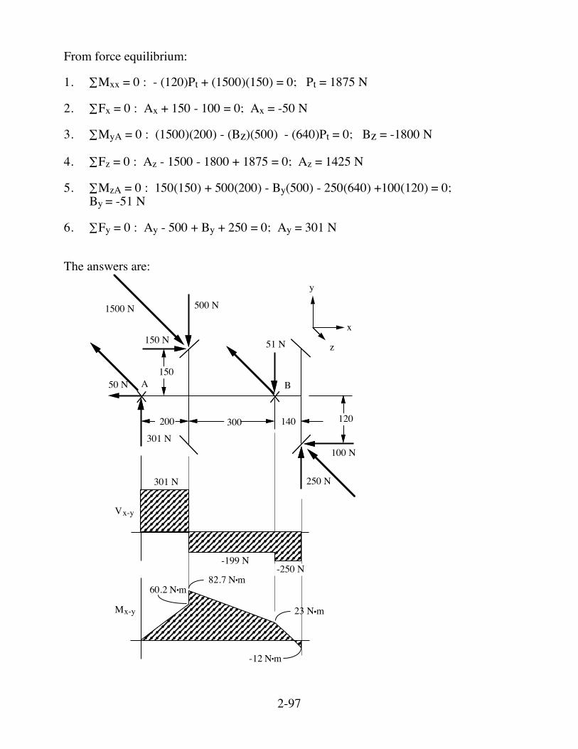
From force equilibrium: 1. ∑Mxx = 0 : - (120)Pt + (1500)(150) = 0; Pt = 1875 N 2. ∑Fx = 0 : Ax + 150 - 100 = 0; Ax = -50 N 3. ∑MyA = 0 : (1500)(200) - (Bz)(500) - (640)Pt = 0; Bz = -1800 N 4. ∑Fz = 0 : Az - 1500 - 1800 + 1875 = 0; Az = 1425 N 5. ∑MzA = 0 : 150(150) + 500(200) - By(500) - 250(640) +100(120) = 0; By = -51 N 6. ∑Fy = 0 : Ay - 500 + By + 250 = 0; Ay = 301 N The answers are:
A B
250 N
100 N
120140300200
150
500 N
150 N
50 N
301 N
51 N
1500 N
301 N
-199 N-250 N
60.2 N•m82.7 N•m
-12 N•m
Vx-y
Mx-y 23 N•m
y
x
z
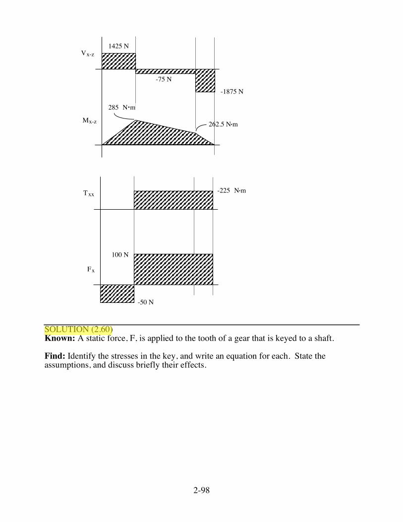
2-98
1425 N
-75 N
-1875 N
Mx-z
Vx-z
N•m285
N•m262.5
100 N
N•m-225
Fx
Txx
-50 N SOLUTION (2.60) Known: A static force, F, is applied to the tooth of a gear that is keyed to a shaft. Find: Identify the stresses in the key, and write an equation for each. State the assumptions, and discuss briefly their effects.

2-99
Schematic and Given Data:
r
t
bR
t/2
A
A
F
L
Key
Section on A-A
Assumption: The compressive forces on each side of the key are uniform. Analysis: 1. Compression on key sides
b
t
(σc • L • t2)r ≈ FR ; Hence, σc ≈ 2FR
(L) (t) (r) or more precisely,
σcL • t2 (r - t4) = FR so, σc = 2FR
Lt (r - t/4) 2. Key shear
τ (bL)r = FR ; hence, τ = FRbLr
2-100
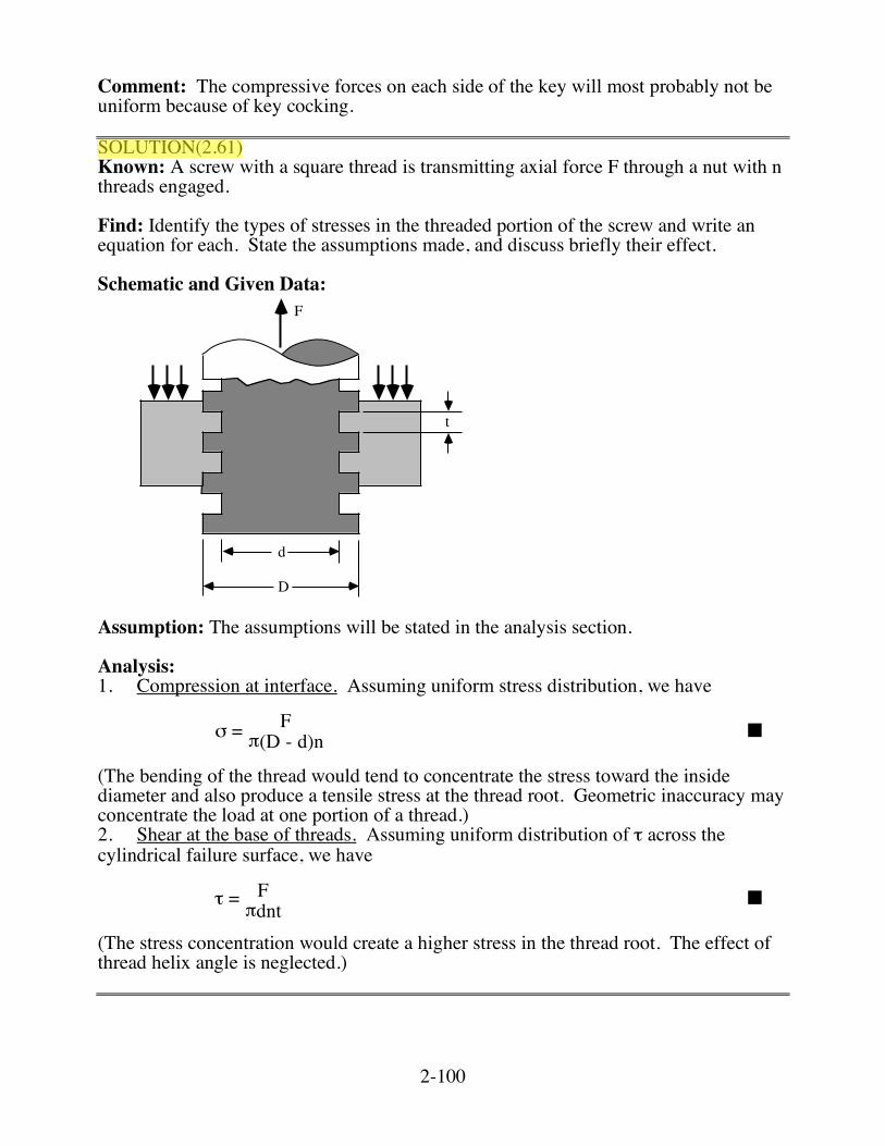
Comment: The compressive forces on each side of the key will most probably not be uniform because of key cocking. SOLUTION(2.61) Known: A screw with a square thread is transmitting axial force F through a nut with n threads engaged. Find: Identify the types of stresses in the threaded portion of the screw and write an equation for each. State the assumptions made, and discuss briefly their effect. Schematic and Given Data:
F
t
D
d
Assumption: The assumptions will be stated in the analysis section. Analysis: 1. Compression at interface. Assuming uniform stress distribution, we have
σ = Fπ(D - d)n ■
(The bending of the thread would tend to concentrate the stress toward the inside diameter and also produce a tensile stress at the thread root. Geometric inaccuracy may concentrate the load at one portion of a thread.) 2. Shear at the base of threads. Assuming uniform distribution of τ across the cylindrical failure surface, we have
τ = Fπdnt ■
(The stress concentration would create a higher stress in the thread root. The effect of thread helix angle is neglected.)