Embed Size (px)
Citation preview
12-25
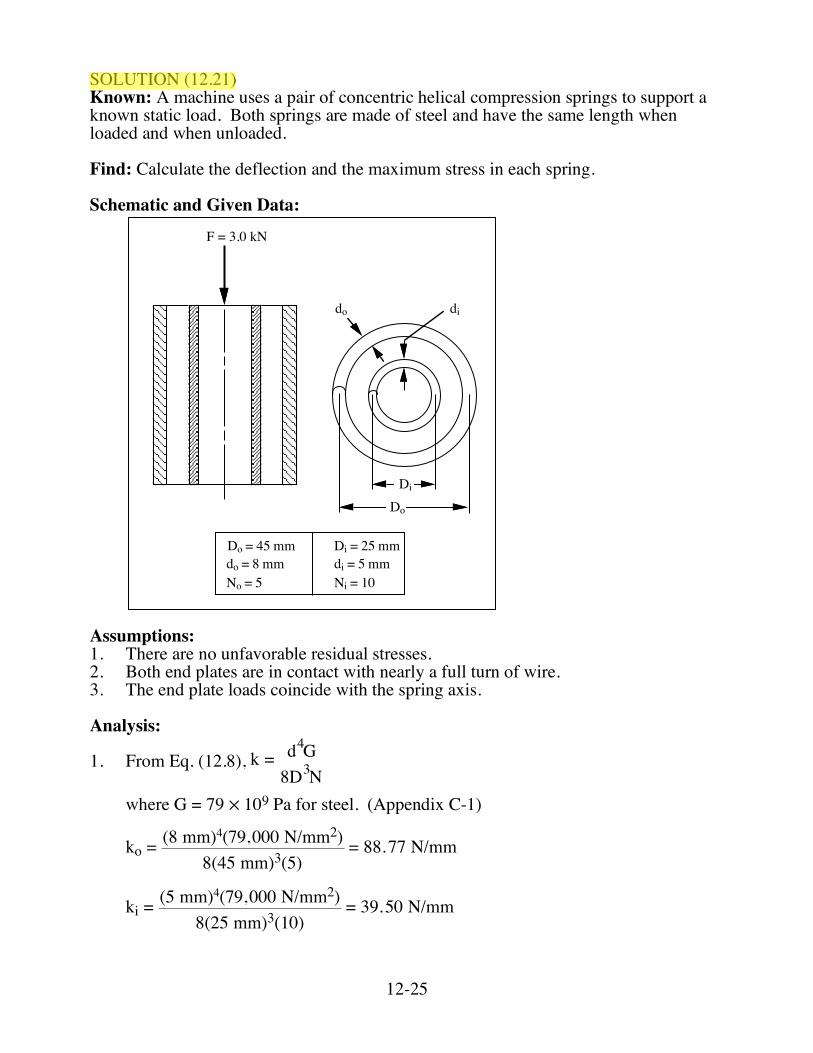
SOLUTION (12.21) Known: A machine uses a pair of concentric helical compression springs to support a known static load. Both springs are made of steel and have the same length when loaded and when unloaded. Find: Calculate the deflection and the maximum stress in each spring. Schematic and Given Data:
F = 3.0 kN
do di
Di
Do
Do = 45 mmdo = 8 mmNo = 5 Ni = 10
di = 5 mmDi = 25 mm
Assumptions: 1. There are no unfavorable residual stresses. 2. Both end plates are in contact with nearly a full turn of wire. 3. The end plate loads coincide with the spring axis. Analysis:
1. From Eq. (12.8), k = d4G8D3N
where G = 79 ✕ 109 Pa for steel. (Appendix C-1)
ko = (8 mm)4(79,000 N/mm2)
8(45 mm)3(5) = 88.77 N/mm
ki = (5 mm)4(79,000 N/mm2)
8(25 mm)3(10) = 39.50 N/mm
12-26
2. From Eq. (12.8), k = Fδor δ = Fk
δ = 3,000(39.5 + 88.77) = 23.39 mm ■
3. Using F = kδ, we can calculate the force on each spring. Fo = koδ = (88.77 N/mm)(23.39 mm) = 2076 N Fi = kiδ = (39.50 N/mm)(23.39 mm) = 924 N 4. Using Fig. 12.4, we can find Ks values for each spring. For outer spring, C = 45/8 = 5.63, Ks = 1.09 For inner spring, C = 25/5 = 5.00, Ks = 1.10
5. From Eq. (12.6), ! = 8FD"d3
Ks
τo =8(2076)(45)
π(8)3(1.09) = 506 MPa ■
τi =8(924)(25)π(5)3
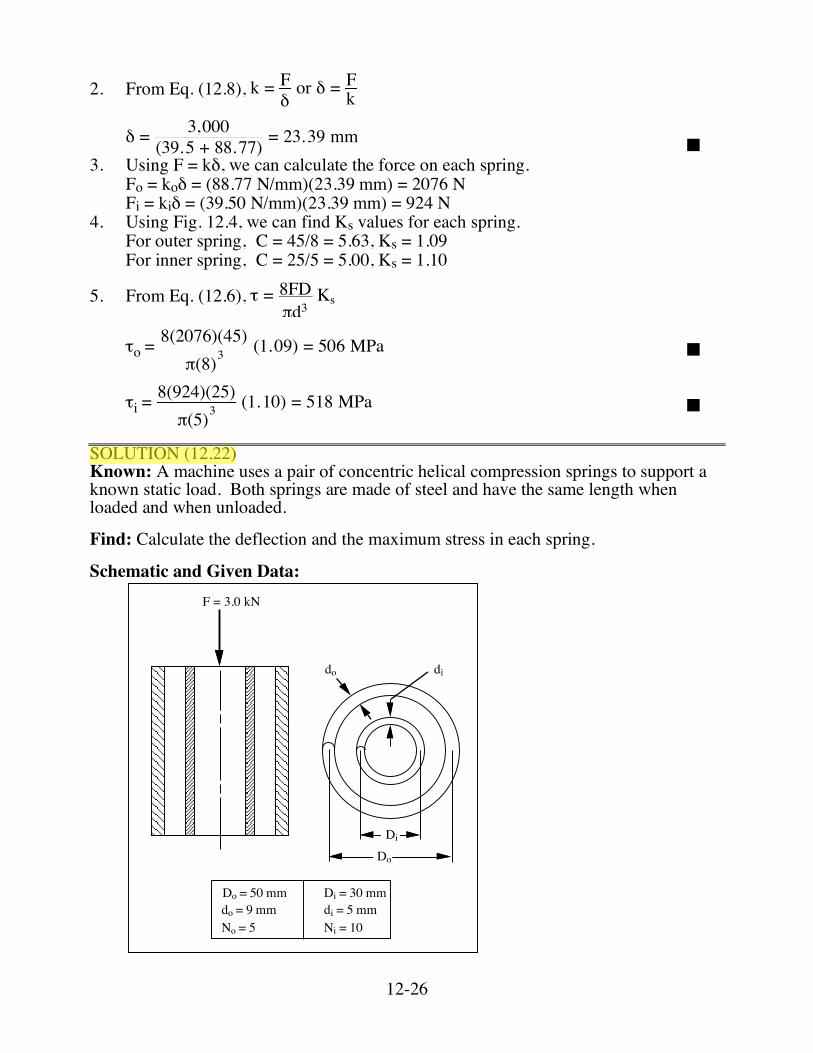
(1.10) = 518 MPa ■ SOLUTION (12.22) Known: A machine uses a pair of concentric helical compression springs to support a known static load. Both springs are made of steel and have the same length when loaded and when unloaded. Find: Calculate the deflection and the maximum stress in each spring. Schematic and Given Data:
F = 3.0 kN
do di
Di
Do
Do = 50 mmdo = 9 mmNo = 5 Ni = 10
di = 5 mmDi = 30 mm
12-27
Assumptions: 1. There are no unfavorable residual stresses. 2. Both end plates are in contact with nearly a full turn of wire. 3. The end plate loads coincide with the spring axis. Analysis:
1. From Eq. (12.8), k = d4G8D3N
where G = 79 ✕ 109 Pa for steel. (Appendix C-1)
ko = (9 mm)4(79,000 N/mm2)
8(50 mm)3(5) = 103.66 N/mm
ki = (5 mm)4(79,000 N/mm2)
8(30 mm)3(10) = 22.86 N/mm
2. From Eq. (12.8), k = Fδor δ = Fk
! = 3,000
(22.86 + 103.66) = 23.71 mm ■
3. Using F = kδ, we can calculate the force on each spring. Fo = koδ = (103.66 N/mm)(23.71 mm) = 2458.0 N Fi = kiδ = (22.86 N/mm)(23.71 mm) = 542 N 4. Using Fig. 12.4, we can find Ks values for each spring. For outer spring, C = 50/9 = 5.56 Ks = 1.09 For inner spring, C = 30/5 = 6 Ks = 1.08
5. From Eq. (12.6), ! = 8FD"d3
Ks
!o = 8(2458)(50)"(9)3
(1.09) = 467.94 MPa ■
!i = 8(542)(30)"(5)3
(1.08) = 357.75 MPa ■
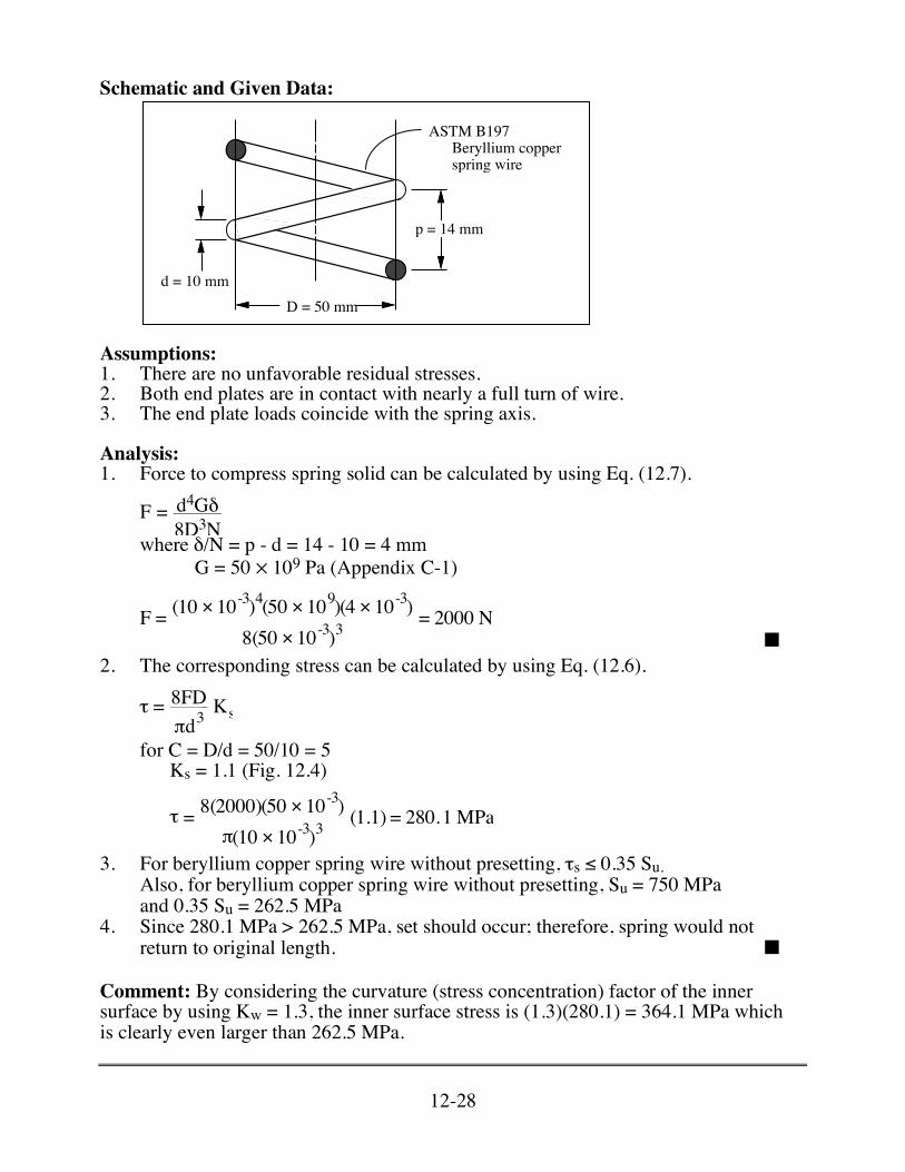
SOLUTION (12.23) Known: A helical coil spring with given D and d is wound with a known pitch value. The material is ASTM B197 beryllium copper spring wire. Find: If the spring is compressed solid, would you expect it to return to its original free-length when the force is removed?
12-28
Schematic and Given Data:
ASTM B197!!!!!!Beryllium copper !!!!!!spring wire!!
p = 14 mm
d = 10 mmD = 50 mm
Assumptions: 1. There are no unfavorable residual stresses. 2. Both end plates are in contact with nearly a full turn of wire. 3. The end plate loads coincide with the spring axis. Analysis: 1. Force to compress spring solid can be calculated by using Eq. (12.7).
F = d4G!
8D3N where δ/N = p - d = 14 - 10 = 4 mm G = 50 ✕ 109 Pa (Appendix C-1)
F = (10 × 10
-3)4(50 × 109)(4 × 10⁻³)8(50 × 10-3)3
= 2000 N ■
2. The corresponding stress can be calculated by using Eq. (12.6).
τ = 8FDπd3
Ks
for C = D/d = 50/10 = 5 Ks = 1.1 (Fig. 12.4)
τ = 8(2000)(50 × 10
-3)π(10 × 10-3)3
(1.1) = 280.1 MPa
3. For beryllium copper spring wire without presetting, τs ≤ 0.35 Su. Also, for beryllium copper spring wire without presetting, Su = 750 MPa
and 0.35 Su = 262.5 MPa 4. Since 280.1 MPa > 262.5 MPa, set should occur; therefore, spring would not
return to original length. ■ Comment: By considering the curvature (stress concentration) factor of the inner surface by using Kw = 1.3, the inner surface stress is (1.3)(280.1) = 364.1 MPa which is clearly even larger than 262.5 MPa.
12-31
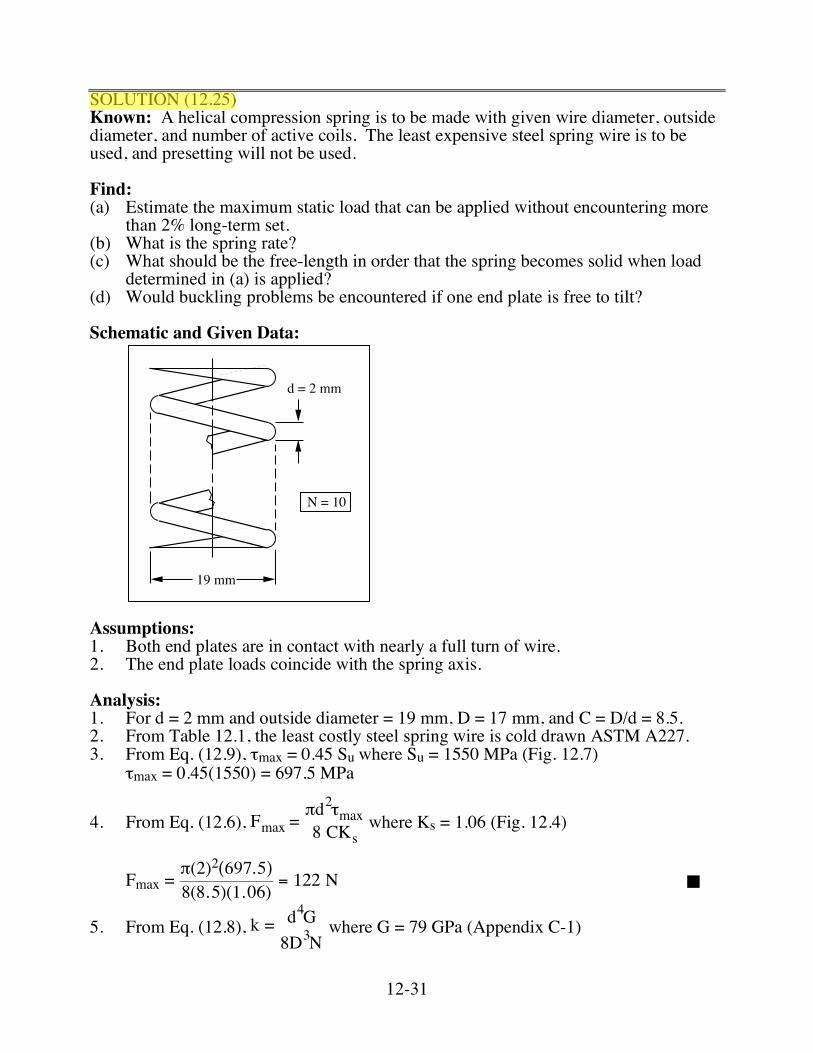
SOLUTION (12.25) Known: A helical compression spring is to be made with given wire diameter, outside diameter, and number of active coils. The least expensive steel spring wire is to be used, and presetting will not be used. Find: (a) Estimate the maximum static load that can be applied without encountering more
than 2% long-term set. (b) What is the spring rate? (c) What should be the free-length in order that the spring becomes solid when load
determined in (a) is applied? (d) Would buckling problems be encountered if one end plate is free to tilt? Schematic and Given Data:
19 mm
d = 2 mm
N = 10
Assumptions: 1. Both end plates are in contact with nearly a full turn of wire. 2. The end plate loads coincide with the spring axis. Analysis: 1. For d = 2 mm and outside diameter = 19 mm, D = 17 mm, and C = D/d = 8.5. 2. From Table 12.1, the least costly steel spring wire is cold drawn ASTM A227. 3. From Eq. (12.9), τmax = 0.45 Su where Su = 1550 MPa (Fig. 12.7) τmax = 0.45(1550) = 697.5 MPa
4. From Eq. (12.6), Fmax =πd2τmax8 CKs
where Ks = 1.06 (Fig. 12.4)
Fmax = !(2)2(697.5)8(8.5)(1.06)
= 122 " ■
5. From Eq. (12.8), k = d4G8D3N
where G = 79 GPa (Appendix C-1)
12-32
k = 24(79,000)
8(17)3(10) = 3.22 N/mm ■
6. The amount of deflection when Fmax = 122 N is applied to the spring is
!s = Fmax/k = 1223.22
= 37.89 mm
From Fig. 12.8(d), Ls = Ntd Ls = (N + 2)d = (10 + 2)2 = 24 mm Therefore, Lf = Ls + δs Lf = 24 + 37.89 = 61.89 mm ■ 7. Lf/D = 61.89/17 = 3.64 δs/Lf = 37.89/61.89 = 0.612 From Fig. 12.10, for the case B, no buckling should occur. ■
12-35
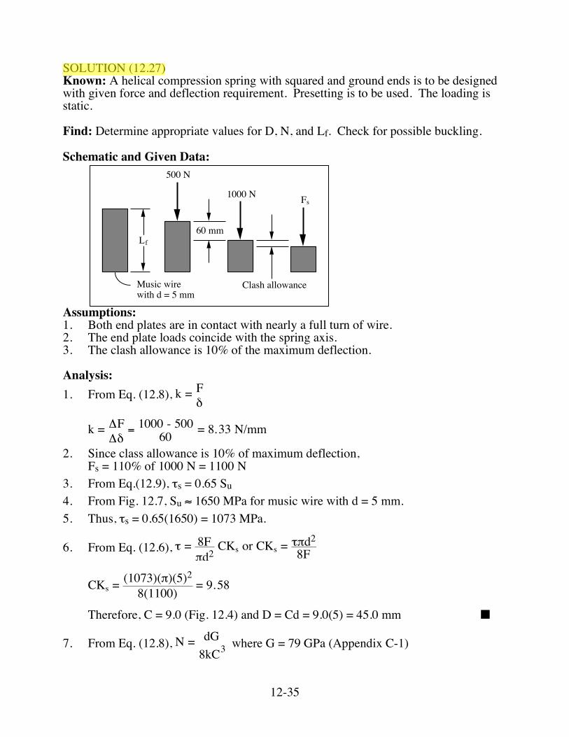
SOLUTION (12.27) Known: A helical compression spring with squared and ground ends is to be designed with given force and deflection requirement. Presetting is to be used. The loading is static. Find: Determine appropriate values for D, N, and Lf. Check for possible buckling. Schematic and Given Data:
Clash allowanceMusic wire
with d = 5 mm
60 mm
1000 N
500 N
Fs
Lf
Assumptions: 1. Both end plates are in contact with nearly a full turn of wire. 2. The end plate loads coincide with the spring axis. 3. The clash allowance is 10% of the maximum deflection. Analysis: 1. From Eq. (12.8), k = F
!
k = ΔFΔδ
= 1000 - 50060 = 8.33 N/mm
2. Since class allowance is 10% of maximum deflection, Fs = 110% of 1000 N = 1100 N
3. From Eq.(12.9), τs = 0.65 Su
4. From Fig. 12.7, Su ≈ 1650 MPa for music wire with d = 5 mm.
5. Thus, τs = 0.65(1650) = 1073 MPa.
6. From Eq. (12.6), ! = 8F"d2
CKs or CKs = !"d2
8F
CKs = (1073)(!)(5)2
8(1100) = 9.58
Therefore, C = 9.0 (Fig. 12.4) and D = Cd = 9.0(5) = 45.0 mm ■
7. From Eq. (12.8), N = dG8kC3
where G = 79 GPa (Appendix C-1)
12-36
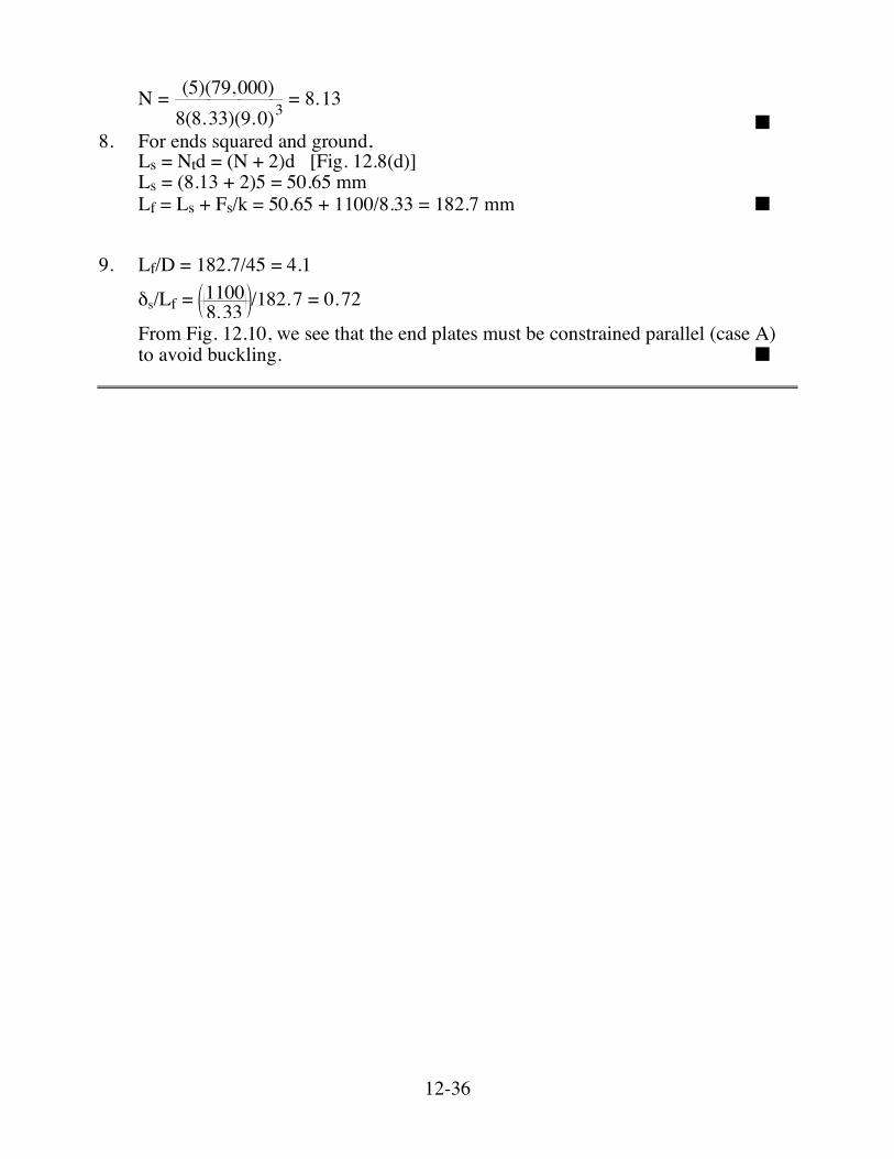
N = (5)(79,000)
8(8.33)(9.0)3= 8.13
■ 8. For ends squared and ground, Ls = Ntd = (N + 2)d [Fig. 12.8(d)] Ls = (8.13 + 2)5 = 50.65 mm Lf = Ls + Fs/k = 50.65 + 1100/8.33 = 182.7 mm ■ 9. Lf/D = 182.7/45 = 4.1
!s/Lf = 11008.33 /182.7 = 0.72
From Fig. 12.10, we see that the end plates must be constrained parallel (case A) to avoid buckling. ■
12-37
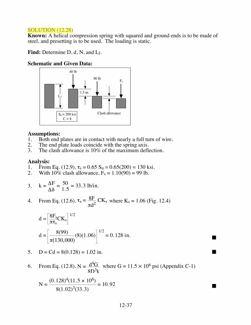
SOLUTION (12.28) Known: A helical compression spring with squared and ground ends is to be made of steel, and presetting is to be used. The loading is static. Find: Determine D, d, N, and Lf. Schematic and Given Data:
Clash allowance
1.5 in.
40 lb
90 lb Fs
Lf
Su = 200 ksiC = 8
Assumptions: 1. Both end plates are in contact with nearly a full turn of wire. 2. The end plate loads coincide with the spring axis. 3. The clash allowance is 10% of the maximum deflection. Analysis: 1. From Eq. (12.9), τs = 0.65 Su = 0.65(200) = 130 ksi. 2. With 10% clash allowance, Fs = 1.10(90) = 99 lb.
3. k = ΔFΔδ
= 501.5 = 33.3 lb/in.
4. From Eq. (12.6), !s = 8F"d2
CKs where Ks = 1.06 (Fig. 12.4)
d = 8Fs
!"sCKs
1/2
d = 8(99)!(130,000)
(8)(1.06) 1/2
= 0.128 in. ■
5. D = Cd = 8(0.128) = 1.02 in. ■ 6. From Eq. (12.8), N = d4G
8D3k where G = 11.5 ✕ 106 psi (Appendix C-1)
N = (0.128)4(11.5 ! 106)8(1.02)3(33.3)
= 10.92 ■
12-38
7. From Fig. 12.8, for squared and ground ends, Ls = Ntd or Ls = (N + 2)d Ls = (10.92 + 2)(0.128) = 1.65 in. Lf = Ls + !s = Ls + Fsk Lf = 1.65 + 9933.3 = 4.62 in. ■ Comment: Lf/D = 4.621.02 = 4.53 δs/Lf = ( )99
33.3 /4.62 = 0.644 From Fig. 12.10, we can see that the end plates should be constrained parallel to avoid buckling.
12-39
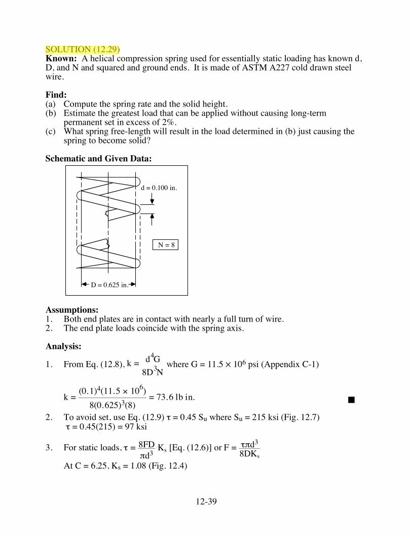
SOLUTION (12.29) Known: A helical compression spring used for essentially static loading has known d, D, and N and squared and ground ends. It is made of ASTM A227 cold drawn steel wire. Find: (a) Compute the spring rate and the solid height. (b) Estimate the greatest load that can be applied without causing long-term
permanent set in excess of 2%. (c) What spring free-length will result in the load determined in (b) just causing the
spring to become solid? Schematic and Given Data:
d = 0.100 in.
N = 8
D = 0.625 in.
Assumptions: 1. Both end plates are in contact with nearly a full turn of wire. 2. The end plate loads coincide with the spring axis. Analysis:
1. From Eq. (12.8), k = d4G8D3N
where G = 11.5 ✕ 106 psi (Appendix C-1)
k = (0.1)4(11.5 ! 106)8(0.625)3(8)
= 73.6 lb in. ■
2. To avoid set, use Eq. (12.9) τ = 0.45 Su where Su = 215 ksi (Fig. 12.7) τ = 0.45(215) = 97 ksi
3. For static loads, ! = 8FD"d3
Ks [Eq. (12.6)] or F = !"d3
8DKs
At C = 6.25, Ks = 1.08 (Fig. 12.4)
12-40
Thus, F = (97,000)!(0.1)3
8(0.625)(1.08) = 56.4 lb ■
4. Ls = (N + 2)d = (10)(0.1) = 1.0 in. ■ Lf = Ls + Fs/k = 1.0 + 56.4/73.6 = 1.77 in. ■
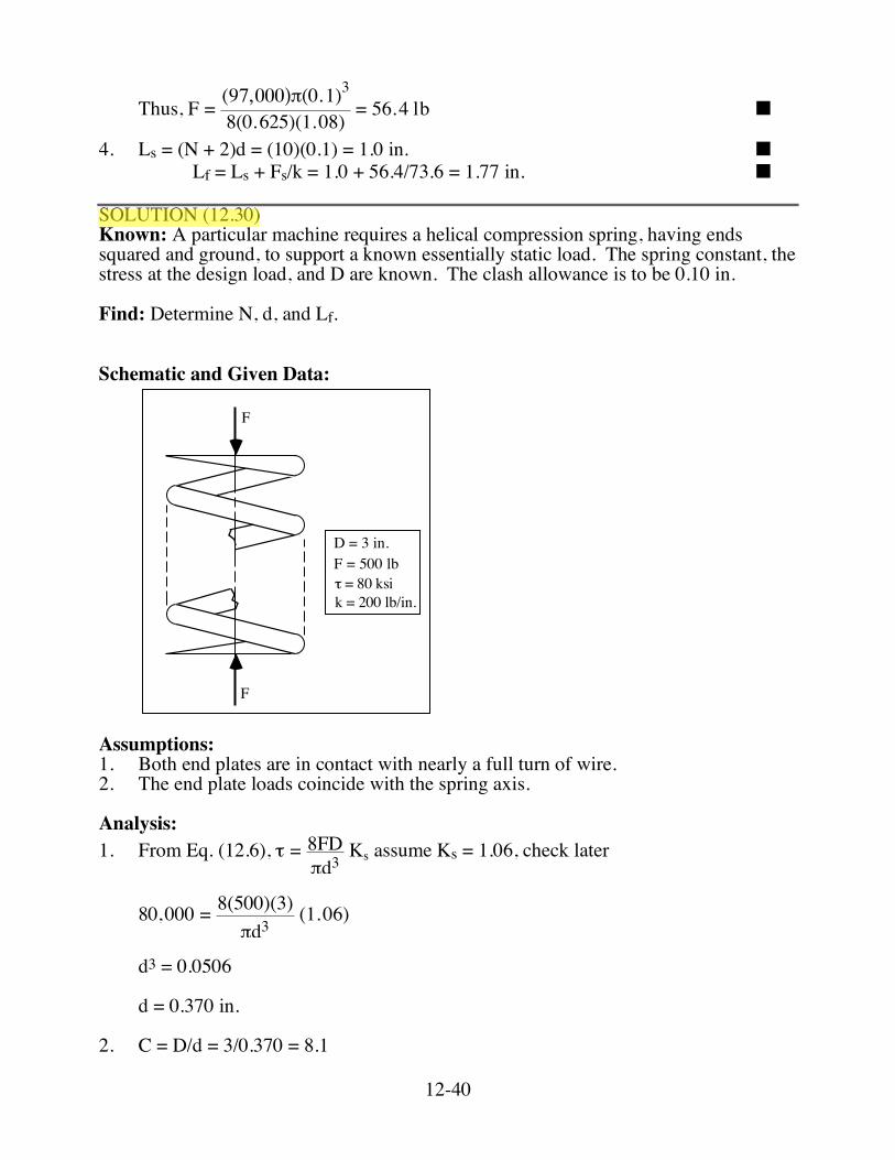
SOLUTION (12.30) Known: A particular machine requires a helical compression spring, having ends squared and ground, to support a known essentially static load. The spring constant, the stress at the design load, and D are known. The clash allowance is to be 0.10 in. Find: Determine N, d, and Lf. Schematic and Given Data:
F
F
D = 3 in.F = 500 lb
k = 200 lb/in.! = 80 ksi
Assumptions: 1. Both end plates are in contact with nearly a full turn of wire. 2. The end plate loads coincide with the spring axis. Analysis: 1. From Eq. (12.6), ! = 8FD
"d3 Ks assume Ks = 1.06, check later
80,000 = 8(500)(3)
!d3 (1.06)
d3 = 0.0506 d = 0.370 in. 2. C = D/d = 3/0.370 = 8.1
12-41
From Fig. 12.4, Ks = 1.06 Therefore, d = 0.370 in. ■
3. From Eq. (12.8), k = d4G8D3N
or N = d4G8kD3
where G = 11.5 ✕ 106 psi (Appendix C-1)
N = (0.370)4(11.5 ! 106)8(200)(3)3
= 5.0 ■ 4. Ls = (N + 2)d = (5.0 + 2)(0.370) = 2.59 in. Expansion from solid = 0.1 + 500/200 = 2.6 in. Lf = 2.59 + 2.6 = 5.19 in. ■
12-53
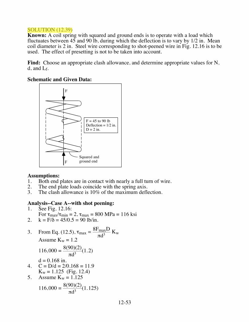
SOLUTION (12.39) Known: A coil spring with squared and ground ends is to operate with a load which fluctuates between 45 and 90 lb, during which the deflection is to vary by 1/2 in. Mean coil diameter is 2 in. Steel wire corresponding to shot-peened wire in Fig. 12.16 is to be used. The effect of presetting is not to be taken into account. Find: Choose an appropriate clash allowance, and determine appropriate values for N, d, and Lf. Schematic and Given Data:
F
FSquared and ground end
F = 45 to 90 lbDeflection = 1/2 in.D = 2 in.
Assumptions: 1. Both end plates are in contact with nearly a full turn of wire. 2. The end plate loads coincide with the spring axis. 3. The clash allowance is 10% of the maximum deflection. Analysis--Case A--with shot peening: 1. See Fig. 12.16: For τmax/τmin = 2, τmax = 800 MPa = 116 ksi 2. k = F/δ = 45/0.5 = 90 lb/in.
3. From Eq. (12.5), !max = 8FmaxD"d3 Kw
Assume Kw = 1.2
116,000 = 8(90)(2)
!d3 (1.2)
d = 0.168 in. 4. C = D/d = 2/0.168 = 11.9 Kw = 1.125 (Fig. 12.4) 5. Assume Kw = 1.125
116,000 = 8(90)(2)
!d3 (1.125)
12-54
d = 0.164 in. 6. C = D/d = 12.19, Kw ≈ 1.12 From Eq. (12.5), d = 0.164 in. ■
7. From Eq. (12.8), k = d4G8D3N
or N = d4G
8D3k
where G = 11.5 ✕ 106 psi (Appendix C-1)
N = (0.164)4(11.5 ! 106)
8(2)3(90) = 1.44
■
8. Clash allowance = 10%
δsolid = (1.1)90 lb90 lb/in. = 1.1 in.
Solid height = (N + 2)d = (1.44 + 2)(0.164) = 0.565 in. Lf = 0.565+ 1.1 = 1.665 in. ■ Analysis--Case B--without shot peening: 1. See Fig. 12.16: For τmax/τmin = 2, τmax = 640 MPa = 93 ksi 2. k = F/δ = 45/0.5 = 90 lb/in.
3. From Eq. (12.5), !max = 8FmaxD"d3 Kw
Assume Kw = 1.2
93,000 = 8(90)(2)
!d3 (1.2)
d = 0.181 in. 4. D/d = 2/0.181 = 11.1 Kw = 1.13 (Fig. 12.4) 5. Assume Kw = 1.13
93,000 = 8(90)(2)
!d3 (1.13)
d = 0.177 in. 6. D/d = 11.3, Kw ≈ 1.13 Thus, d = 0.177 in. ■
7. From Eq. (12.8), k = d4G8D3N
or N = d4G
8D3k
where G = 11.5 ✕ 106 psi (Appendix C-1)
N = (0.177)4(11.5 ! 106)
8(2)3(90) = 1.96
■
8. Clash allowance = 10 %
12-55
δsolid = (1.1)90 lb90 lb/in. = 1.1 in.
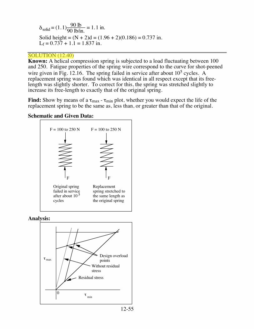
Solid height = (N + 2)d = (1.96 + 2)(0.186) = 0.737 in. Lf = 0.737 + 1.1 = 1.837 in. SOLUTION (12.40) Known: A helical compression spring is subjected to a load fluctuating between 100 and 250. Fatigue properties of the spring wire correspond to the curve for shot-peened wire given in Fig. 12.16. The spring failed in service after about 105 cycles. A replacement spring was found which was identical in all respect except that its free-length was slightly shorter. To correct for this, the spring was stretched slightly to increase its free-length to exactly that of the original spring. Find: Show by means of a τmax - τmin plot, whether you would expect the life of the replacement spring to be the same as, less than, or greater than that of the original. Schematic and Given Data:
F = 100 to 250 N F = 100 to 250 N
Original spring failed in service after about 10 cycles
5
Replacement spring stretched to the same length as the original spring
F F
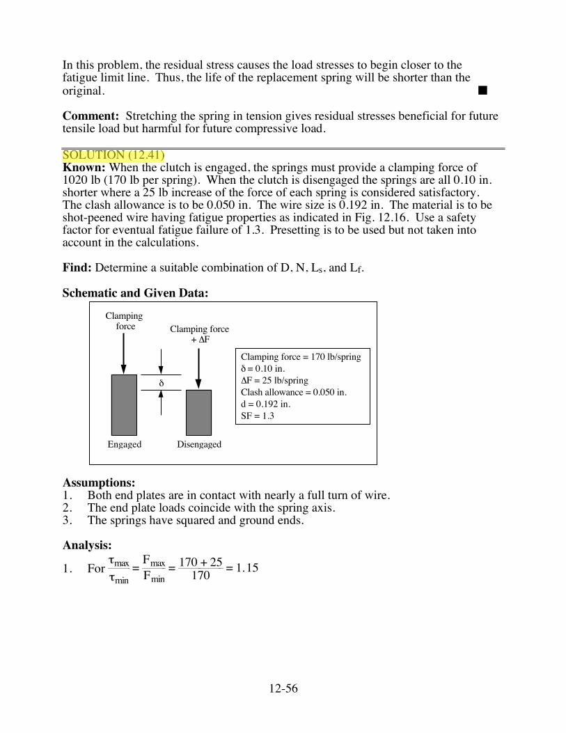
Analysis:
0
Design overloadpoints!max
Residual stress
Without residualstress
min!
12-56
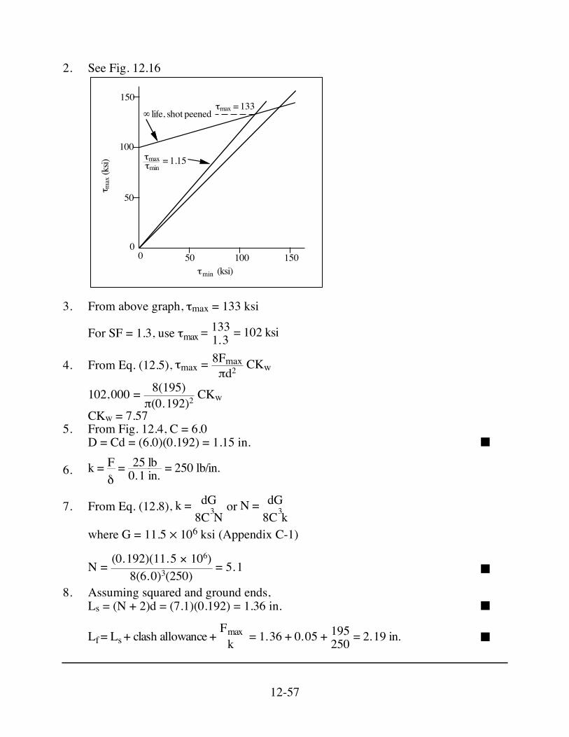
In this problem, the residual stress causes the load stresses to begin closer to the fatigue limit line. Thus, the life of the replacement spring will be shorter than the original. ■ Comment: Stretching the spring in tension gives residual stresses beneficial for future tensile load but harmful for future compressive load. SOLUTION (12.41) Known: When the clutch is engaged, the springs must provide a clamping force of 1020 lb (170 lb per spring). When the clutch is disengaged the springs are all 0.10 in. shorter where a 25 lb increase of the force of each spring is considered satisfactory. The clash allowance is to be 0.050 in. The wire size is 0.192 in. The material is to be shot-peened wire having fatigue properties as indicated in Fig. 12.16. Use a safety factor for eventual fatigue failure of 1.3. Presetting is to be used but not taken into account in the calculations. Find: Determine a suitable combination of D, N, Ls, and Lf. Schematic and Given Data:
Engaged Disengaged
Clamping force
!
Clamping force+ "F
Clamping force = 170 lb/spring! = 0.10 in."F = 25 lb/springClash allowance = 0.050 in.d = 0.192 in.SF = 1.3
Assumptions: 1. Both end plates are in contact with nearly a full turn of wire. 2. The end plate loads coincide with the spring axis. 3. The springs have squared and ground ends. Analysis:
1. For τmaxτmin
= FmaxFmin= 170 + 25170 = 1.15
12-57
2. See Fig. 12.16
50 100 15000
50
100
150! m
ax(k
si)
(ksi)min!
!max!min
= 1.15
!max = 133" life, shot peened
3. From above graph, τmax = 133 ksi
For SF = 1.3, use !max =1331.3 = 102 ksi
4. From Eq. (12.5), !max = 8Fmax"d2 CKw
102,000 = 8(195)
!(0.192)2 CKw
CKw = 7.57 5. From Fig. 12.4, C = 6.0 D = Cd = (6.0)(0.192) = 1.15 in. ■
6. k = Fδ= 25 lb0.1 in. = 250 lb/in.
7. From Eq. (12.8), k = dG8C3N
or N = dG8C3k
where G = 11.5 ✕ 106 ksi (Appendix C-1)
N = (0.192)(11.5 ! 106)8(6.0)3(250)
= 5.1 ■
8. Assuming squared and ground ends, Ls = (N + 2)d = (7.1)(0.192) = 1.36 in. ■
Lf= Ls+ clash allowance +Fmaxk = 1.36 + 0.05 + 195250 = 2.19 in. ■
12-58
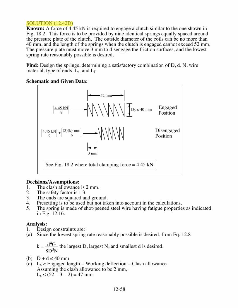
SOLUTION (12.42D) Known: A force of 4.45 kN is required to engage a clutch similar to the one shown in Fig. 18.2. This force is to be provided by nine identical springs equally spaced around the pressure plate of the clutch. The outside diameter of the coils can be no more than 40 mm, and the length of the springs when the clutch is engaged cannot exceed 52 mm. The pressure plate must move 3 mm to disengage the friction surfaces, and the lowest spring rate reasonably possible is desired. Find: Design the springs, determining a satisfactory combination of D, d, N, wire material, type of ends, Ls, and Lf. Schematic and Given Data:
52 mm
3 mm
4.45 kN9
4.45 kN9
+ (3)(k) mm9
Engaged Position
DisengagedPosition
D0 ! 40 mm
See Fig. 18.2 where total clamping force = 4.45 kN
Decisions/Assumptions: 1. The clash allowance is 2 mm. 2. The safety factor is 1.3. 3. The ends are squared and ground. 4. Presetting is to be used but not taken into account in the calculations. 5. The spring is made of shot-peened steel wire having fatigue properties as indicated
in Fig. 12.16. Analysis: 1. Design constraints are: (a) Since the lowest spring rate reasonably possible is desired, from Eq. 12.8
k = d4G8D3N
the largest D, largest N, and smallest d is desired. (b) D + d ≤ 40 mm (c) Ls ≥ Engaged length − Working deflection − Clash allowance Assuming the clash allowance to be 2 mm, Ls ≤ (52 − 3 − 2) = 47 mm
12-59
2. First, choose C = 8.0, N = 9, and D = 35 mm. Then, d = 4.375 mm and D + d < 40 mm.
Ls = (N + 2)d = 48.1 mm which is too long. Thus, choose a smaller N. 3. Choose N = 7.5. Then, Ls = (7.5 + 2)4.375 = 41.6 mm which is satisfactory. 4. From Eq. 12.8, where G = 79 MPa for a steel wire.
k = (4.375)4(79,000)8(35)3(7.5)
= 11.25 N/mm
5. Lf = Fengagedk + Lengaged = (4450/9)
11.25 + 52 = 95.95 mm 6. Fengaged = 4450/9 = 494 N, Fdisengaged = (95.95 − 49)11.25 = 528 N
Thus, Fmax
Fmin = !max
!min = 528
494 = 1.07 " 1
7. From Fig. 12.16, for infinite-life with shot-peening, τmax = 965 MPa. With a safety factor of 1.3, τmax = 965/1.3 = 742 MPa. 8. Using Eq. 12.5,
!disengaged = 8Fdisengaged
"d2 CKw where Kw = 1.18 (Fig. 12.4)
!diseng. = 8(528)" 4.375 # 10-3 2
(8)(1.18) = 663 MPa
Therefore, τdiseng. < τmax 9. Checking for buckling using Fig. 12.10, Lf/D = 95.95/35 = 2.74. Thus, the spring
will not buckle. 10. In summarizing the answers, the spring is made of shot-peened steel wire having
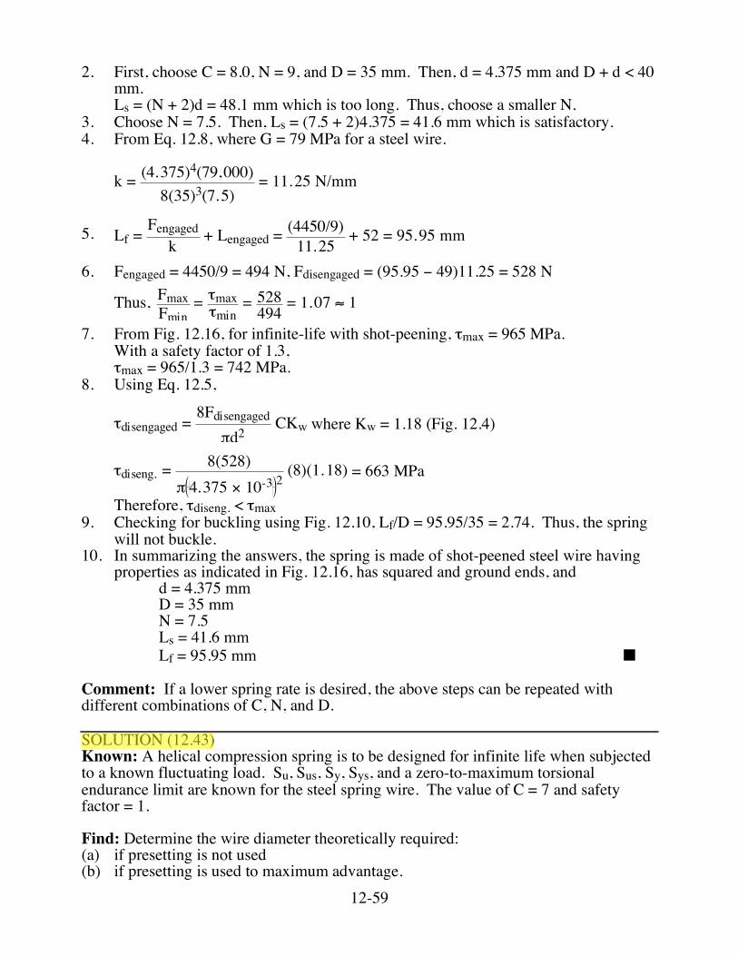
properties as indicated in Fig. 12.16, has squared and ground ends, and d = 4.375 mm D = 35 mm N = 7.5 Ls = 41.6 mm Lf = 95.95 mm ■ Comment: If a lower spring rate is desired, the above steps can be repeated with different combinations of C, N, and D. SOLUTION (12.43) Known: A helical compression spring is to be designed for infinite life when subjected to a known fluctuating load. Su, Sus, Sy, Sys, and a zero-to-maximum torsional endurance limit are known for the steel spring wire. The value of C = 7 and safety factor = 1. Find: Determine the wire diameter theoretically required: (a) if presetting is not used (b) if presetting is used to maximum advantage.
12-60
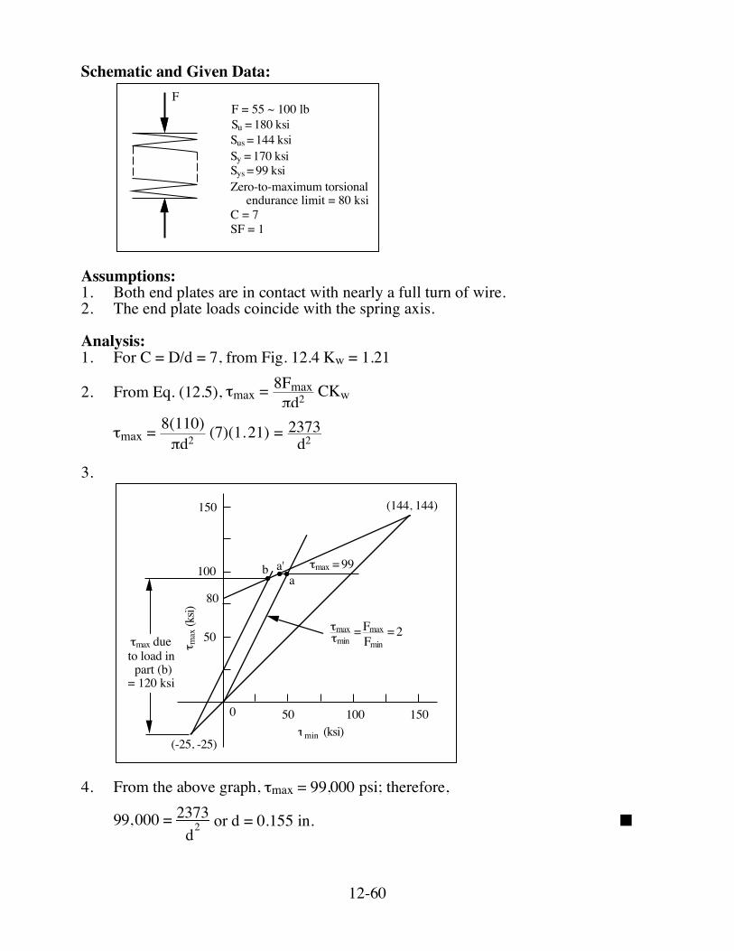
Schematic and Given Data:
FF = 55 ~ 100 lb
Zero-to-maximum torsional endurance limit = 80 ksiC = 7SF = 1
Su = 180 ksiSus = 144 ksiSy = 170 ksiSys = 99 ksi
Assumptions: 1. Both end plates are in contact with nearly a full turn of wire. 2. The end plate loads coincide with the spring axis. Analysis: 1. For C = D/d = 7, from Fig. 12.4 Kw = 1.21
2. From Eq. (12.5), !max = 8Fmax"d2 CKw
!max = 8(110)
"d2 (7)(1.21) = 2373d2
3.
50 100 1500
50
100
150
! max
(ksi)
min (ksi)!(-25, -25)
(144, 144)
b a'a
!max = 99
!max!min
= FmaxFmin
= 2
80
!max dueto load in!part (b)
= 120 ksi
4. From the above graph, τmax = 99,000 psi; therefore,
99,000 = 2373d2
or d = 0.155 in. ■
12-61
(Note: This assumes no yielding is permitted. If slight yielding is okay, the operating point moves from a to aʹ′ on the graph, giving slightly higher τa, which is permitted; therefore, slightly smaller d.)
5. The theoretical maximum τresidual = Sys/3. Assume practical limit is about Sys/4 ≈ 25 ksi. Then from graph, τmax due to load = 120 ksi.
Therefore, 120,000 = 2373d2
or d = 0.141 in. ■
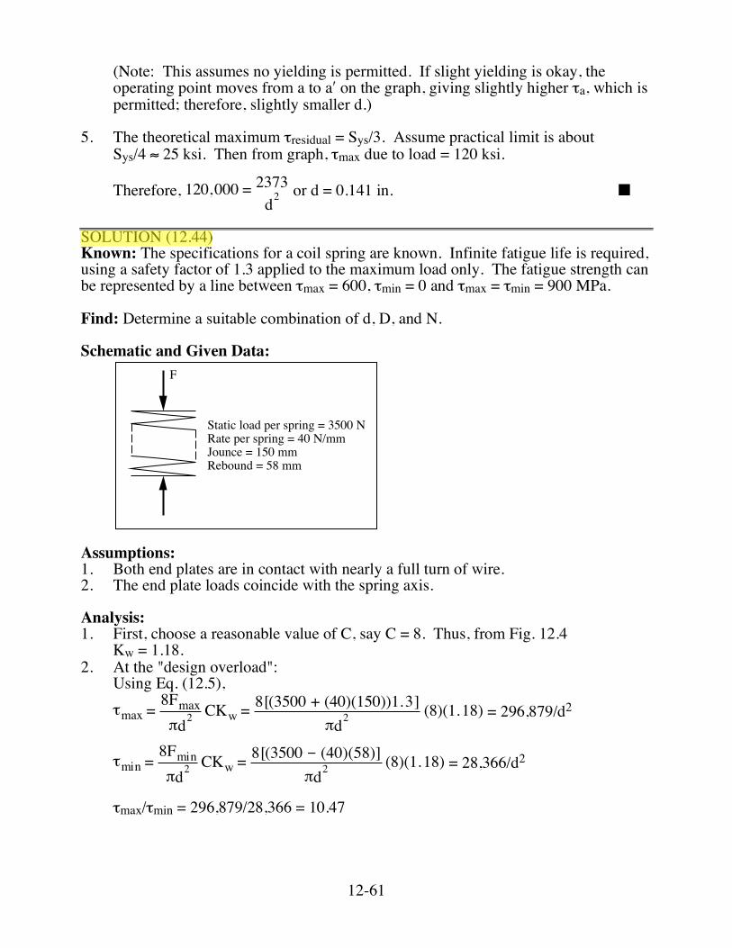
SOLUTION (12.44) Known: The specifications for a coil spring are known. Infinite fatigue life is required, using a safety factor of 1.3 applied to the maximum load only. The fatigue strength can be represented by a line between τmax = 600, τmin = 0 and τmax = τmin = 900 MPa. Find: Determine a suitable combination of d, D, and N. Schematic and Given Data:
F
Static load per spring = 3500 NRate per spring = 40 N/mmJounce = 150 mmRebound = 58 mm
Assumptions: 1. Both end plates are in contact with nearly a full turn of wire. 2. The end plate loads coincide with the spring axis. Analysis: 1. First, choose a reasonable value of C, say C = 8. Thus, from Fig. 12.4 Kw = 1.18. 2. At the "design overload": Using Eq. (12.5),
!max =8Fmax"d2
CKw =8[(3500 + (40)(150))1.3]
"d2(8)(1.18) = 296,879/d2
!min =8Fmin"d2
CKw =8[(3500 # (40)(58)]
"d2(8)(1.18) = 28,366/d2
τmax/τmin = 296,879/28,366 = 10.47
12-62
3.
200 400 600 800 1000
200
400
600
800
1000
0
(900, 900)
!max = 620
!max!min
= 10.47
!min (MPa)
! max
(MPa
)
4. From graph, τmax = 620 MPa.
620 = 296,879d2
or d = 21.88 mm* ■
5. D = Cd = 8(21.88) = 175.0 mm ■
6. From Eq. (12.8), k = dG8NC3
where G = 79 GPa (Appendix C-1)
N = (21.88)(79,000)8(8)3(40)
= 10.55 ■
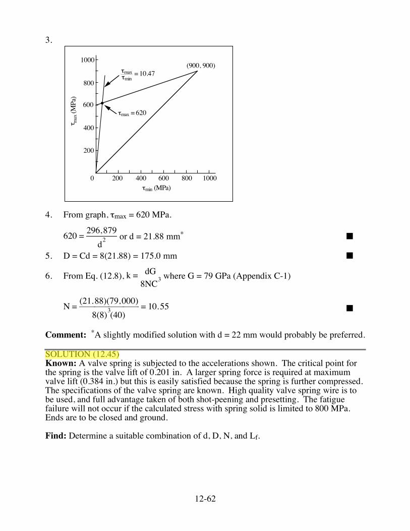
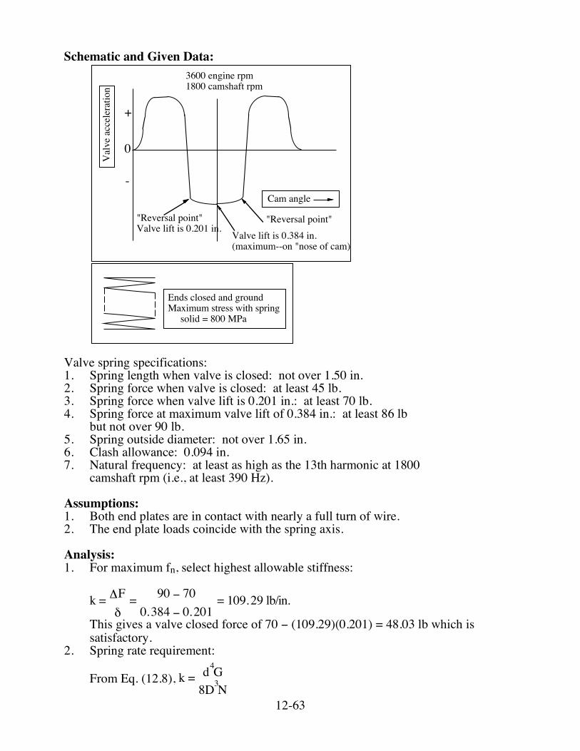
Comment: *A slightly modified solution with d = 22 mm would probably be preferred. SOLUTION (12.45) Known: A valve spring is subjected to the accelerations shown. The critical point for the spring is the valve lift of 0.201 in. A larger spring force is required at maximum valve lift (0.384 in.) but this is easily satisfied because the spring is further compressed. The specifications of the valve spring are known. High quality valve spring wire is to be used, and full advantage taken of both shot-peening and presetting. The fatigue failure will not occur if the calculated stress with spring solid is limited to 800 MPa. Ends are to be closed and ground. Find: Determine a suitable combination of d, D, N, and Lf.
12-63
Schematic and Given Data:
Cam angle
Valve lift is 0.384 in.(maximum--on "nose of cam)
"Reversal point"Valve lift is 0.201 in.
Val
ve a
ccel
erat
ion
3600 engine rpm1800 camshaft rpm
0
+
-
"Reversal point"
Ends closed and groundMaximum stress with spring solid = 800 MPa
Valve spring specifications: 1. Spring length when valve is closed: not over 1.50 in. 2. Spring force when valve is closed: at least 45 lb. 3. Spring force when valve lift is 0.201 in.: at least 70 lb. 4. Spring force at maximum valve lift of 0.384 in.: at least 86 lb but not over 90 lb. 5. Spring outside diameter: not over 1.65 in. 6. Clash allowance: 0.094 in. 7. Natural frequency: at least as high as the 13th harmonic at 1800 camshaft rpm (i.e., at least 390 Hz). Assumptions: 1. Both end plates are in contact with nearly a full turn of wire. 2. The end plate loads coincide with the spring axis. Analysis: 1. For maximum fn, select highest allowable stiffness:
k = ΔFδ= 90 − 700.384 − 0.201
= 109.29 lb/in.
This gives a valve closed force of 70 − (109.29)(0.201) = 48.03 lb which is satisfactory.
2. Spring rate requirement:
From Eq. (12.8), k = d4G8D3N
12-64
where G = 11.5 ✕ 106 psi (Appendix C-1)
Thus, N = d4G8D3k
= d4(11.5 ! 106)8(109.29)D3
Since C = D/d, N = 13,153dC3
(1)
3. Spring length requirement: Valve open length = Ls + 0.384 + clash allowance < 1.50 (N + 2)d + 0.384 + 0.094 < 1.50 (N + 2)d < 1.022 (2) 4. Spring diameter requirement: D + d ≤ 1.65 (3) 5. Spring stress requirement: Fs = 90 + (0.094)(109.29) = 100.27 lb
From Eq. (12.5), !s = 8Fs"d2 CKw
800 MPa = 800(0.145) = 116 ksi
116,000 = 8(100.27)
!d2 CKw
d = CKw454.74 (4)
6. Spring natural frequency requirement:
From Eq. (12.11), fn =13,900dND2
Hz where d and D are in inches.
fn =13,900dND2
= 13,900NDC ≥ 390 Hz (5)
7. For maximum nominal wire stress (for minimum wire mass and high fn), try to satisfy Eq. (4) with smallest Kw.
8. From Fig. 12.4, choose C = 9 for first trial.
From (4), d = 10.46454.74 = 0.152 in. ■
D = Cd = (9)(0.152) = 1.365 in. ■ From (3), D + d = 1.52 in. < 1.65 in.; therefore, OK.
From (1), N = 13,153(0.152)93 = 2.74 ■
From (2), (2.74 + 2)(0.152) = 0.72 in. < 1.022 in.; therefore OK.
From (5), fn =13,900(0.152)(2.74)(1.365)2
= 414 > 390 Hz; therefore OK.
12-65
Lf = Ls + clash allowance + 90 lb/k = (N + 2)d + 0.094 + 90/109.23 = (4.74)(0.152) + 0.094 + 0.824 = 1.638 in. ■ Lf/D = 1.20, Fig. 12.10 shows no buckling concern. 9. For comparison, try solution with C = 7.
From (4), d = 8.49454.74 = 0.137 in. ■
D = Cd = (7)(0.137) = 0.956 in. ■ From (3), D + d = 1.093 in. < 1.65 in.; therefore, OK.
From (1), N = 13,153(0.137)73
= 5.25 ■
From (2), (5.25 + 2)(0.137) = 0.993 in. < 1.022 in.; therefore OK.
From (5), fn =13,900
(5.25)(0.956)(7) = 396 > 380 Hz; therefore OK. (But not as good as C = 9)
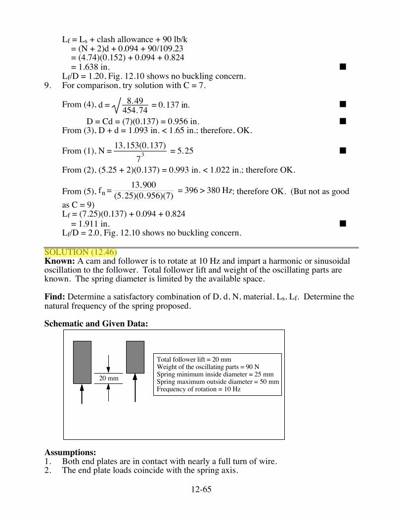
Lf = (7.25)(0.137) + 0.094 + 0.824 = 1.911 in. ■ Lf/D = 2.0, Fig. 12.10 shows no buckling concern. SOLUTION (12.46) Known: A cam and follower is to rotate at 10 Hz and impart a harmonic or sinusoidal oscillation to the follower. Total follower lift and weight of the oscillating parts are known. The spring diameter is limited by the available space. Find: Determine a satisfactory combination of D, d, N, material, Ls, Lf. Determine the natural frequency of the spring proposed. Schematic and Given Data:
20 mm
Total follower lift = 20 mmWeight of the oscillating parts = 90 NSpring minimum inside diameter = 25 mmSpring maximum outside diameter = 50 mmFrequency of rotation = 10 Hz
Assumptions: 1. Both end plates are in contact with nearly a full turn of wire. 2. The end plate loads coincide with the spring axis.
12-66
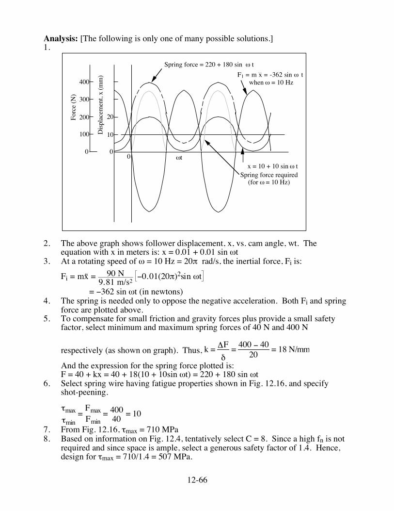
Analysis: [The following is only one of many possible solutions.] 1.
0
10
20
0
100
200
300
400
Disp
lace
men
t, x
(mm
)
Forc
e (N
)
0 !t "
Spring force = 220 + 180 sin ! t
Spring force required(for ! = 10 Hz)
x = 10 + 10 sin ! t
when ! = 10 HzF1 = m x = -362 sin ! t
2. The above graph shows follower displacement, x, vs. cam angle, wt. The
equation with x in meters is: x = 0.01 + 0.01 sin ωt 3. At a rotating speed of ω = 10 Hz = 20π rad/s, the inertial force, Fi is:
Fi = mx = 90 N9.81 m/s2
!0.01(20")2sin #t
= −362 sin ωt (in newtons) 4. The spring is needed only to oppose the negative acceleration. Both Fi and spring
force are plotted above. 5. To compensate for small friction and gravity forces plus provide a small safety
factor, select minimum and maximum spring forces of 40 N and 400 N
respectively (as shown on graph). Thus, k = ΔFδ= 400 − 4020 = 18 N/mm
And the expression for the spring force plotted is: F = 40 + kx = 40 + 18(10 + 10sin ωt) = 220 + 180 sin ωt 6. Select spring wire having fatigue properties shown in Fig. 12.16, and specify
shot-peening.
τmaxτmin
= FmaxFmin= 40040 = 10
7. From Fig. 12.16, τmax = 710 MPa 8. Based on information on Fig. 12.4, tentatively select C = 8. Since a high fn is not
required and since space is ample, select a generous safety factor of 1.4. Hence, design for τmax = 710/1.4 = 507 MPa.
12-67
9. From Eq. (12.5), !max = 8Fmax"d2 CKw
507 = 8(400)
!d2 (9.47)
Therefore, d = 4.36 mm ■ D = Cd = 8(4.36) = 34.9 mm ■
10. From Eq. (12.8), k = dG8NC3
where G = 79 GPa (Appendix C-1)
N = (4.36)(79,000)8(18)(8)3
= 4.67 ■
11. Choose a dash allowance of 10 % of deflection at 400 N load; therefore, Fs = 400(1.1) = 440 N.
12. Ls = (N + 2)d = 6.67(4.36) = 29.08 mm ■ Lf = Ls + Fs/k = 29.08 + 440/18 = 53.52 mm ■
13. From Eq. (12.11a), fn = 353,000dND2 Hz where d and D are in mm
fn =353,000d4.67(34.9)2
= 271 Hz
Lf/D = 53.52/34.9 = 1.53; therefore, no buckling problem. 14. For rotation at 10 Hz, only harmonics would be in resonance during starting and
stopping. Since this cam should give no harmonics, dynamics should be of no concern.
Comment: Since fn and size limitations were easily met, one should consult the spring supplier in search of a lowest cost solution, retaining high reliability. SOLUTION (12.47D) Known: The internet has various sites that contain calculators useful for designing compression springs. Find: Select a calculator that is (a) potentially useful, (b) easy to use, and (c) accurate. Write a short description of the spring calculator. Analysis: This exercise is left for the student.