Embed Size (px)
Citation preview

SOLON Top Class Stand alone sinewave inverter
SOLON Top Class 13/12 SOLON Top Class 20/12 SOLON Top Class 15/24 SOLON Top Class 22/24 SOLON Top Class 30/24 SOLON Top Class 22/48 SOLON Top Class 35/48 SOLON Top Class 25/110 SOLON Top Class 20/36
Instructions for installation
and operation
SOLON Inverters AG CH-8730 Uznach/SG Switzerland www.solon.com

Edition 10/2008 Page 2 / 19
About this Manual
Congratulations on your purchase of a SOLON sinewave inverter. You are the owner of the finest engineered and highest quality sinewave inverter. We have dedicated our products, our services and ourselves to the satisfaction of every customer.
This manual for installation and operation contains important information about this unit. Please familiarise yourself with all the information contained in these instructions before installing and operating this unit. This will help you to get acquainted properly with this unit and make full use of its advanced technical features under all operating conditions. Should you encounter problems while installing or running this unit, please
contact the dealer you purchased the unit from or a dealer authorised by SOLON INVERTERS. Improper assembly, installation and maintenance may impair the safety and function of this unit. For this reason make sure that you understand all the information in this manual before beginning the assembly and installation procedure. SOLON Inverters AG, CH-8730 Uznach/SG
Safety symbols
The following safety symbols have been placed through-out this technical description to indicate dangerous conditions and important safety instructions.
Warning of dangerous electrical tension
Disregarding of warnings may cause heavy bodily injury or death.
Warning / Danger
This indicates a fact or feature very important for the safety of the user and / or which can cause a serious hardware defect if not applied appropriately. Hot Surface
To reduce the risk of burns do not touch surface.
Safety Instructions
In principle the general regulations for security and personal safety are valid for all operation on the sine wave inverter unit.
The inverter was built and examined in accordance with the actual safety regulations for electrical devices. In order to guarantee a safe handling of the equipment, the safety instructions in this manual must be carefully followed.
For any works on the inverter and electrical connections inclusive grounding, protective ground and lightning protection, the national and regional regulations are valid and must be carefully followed.
Any works on the inverter and electrical connections may be implemented only by electrical specialists. An electrical specialist has the suitable technical training, knowledge and experience to recognize and avoid dangers by electricity.
Edition 10/2008 Page 3 / 19
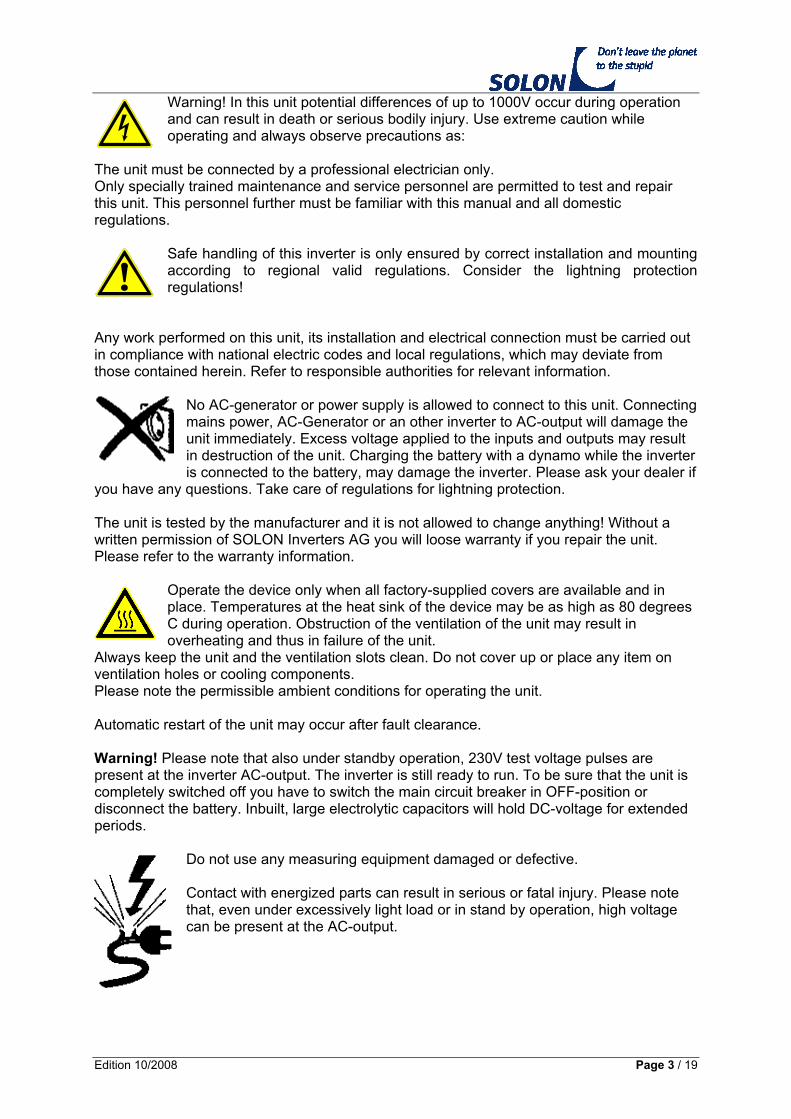
Warning! In this unit potential differences of up to 1000V occur during operation and can result in death or serious bodily injury. Use extreme caution while operating and always observe precautions as:
The unit must be connected by a professional electrician only. Only specially trained maintenance and service personnel are permitted to test and repair this unit. This personnel further must be familiar with this manual and all domestic regulations.
Safe handling of this inverter is only ensured by correct installation and mounting according to regional valid regulations. Consider the lightning protection regulations!
Any work performed on this unit, its installation and electrical connection must be carried out in compliance with national electric codes and local regulations, which may deviate from those contained herein. Refer to responsible authorities for relevant information.
No AC-generator or power supply is allowed to connect to this unit. Connecting mains power, AC-Generator or an other inverter to AC-output will damage the unit immediately. Excess voltage applied to the inputs and outputs may result in destruction of the unit. Charging the battery with a dynamo while the inverter is connected to the battery, may damage the inverter. Please ask your dealer if
you have any questions. Take care of regulations for lightning protection. The unit is tested by the manufacturer and it is not allowed to change anything! Without a written permission of SOLON Inverters AG you will loose warranty if you repair the unit. Please refer to the warranty information.
Operate the device only when all factory-supplied covers are available and in place. Temperatures at the heat sink of the device may be as high as 80 degrees C during operation. Obstruction of the ventilation of the unit may result in overheating and thus in failure of the unit.
Always keep the unit and the ventilation slots clean. Do not cover up or place any item on ventilation holes or cooling components. Please note the permissible ambient conditions for operating the unit. Automatic restart of the unit may occur after fault clearance. Warning! Please note that also under standby operation, 230V test voltage pulses are present at the inverter AC-output. The inverter is still ready to run. To be sure that the unit is completely switched off you have to switch the main circuit breaker in OFF-position or disconnect the battery. Inbuilt, large electrolytic capacitors will hold DC-voltage for extended periods.
Do not use any measuring equipment damaged or defective. Contact with energized parts can result in serious or fatal injury. Please note that, even under excessively light load or in stand by operation, high voltage can be present at the AC-output.

Edition 10/2008 Page 4 / 19
Limitation of liability Since neither the observance of these instructions for installation and operation, nor the conditions and methods of installation, operation, utilisation and maintenance of the unit can be supervised by SOLON Inverters AG, we don't assume any responsibility or liability for loss, damage or costs arising from using this unit or in any way connected with faulty installation, improper operation or incorrect utilisation and maintenance. Furthermore we don't assume any responsibility for infringement of patent rights or violations of the rights of third parties arising from the utilisation of this unit. We reserve the right to make product changes, change technical specifications or these instructions without prior notice. Important! Please be informed that units without CE-declaration can only be used on your own liability in European countries. If you have an unit without CE please contact your local dealer. WARNING! Unauthorised repairs and operation of this device for any use other than that for which it was intended will result in loss of warranty. If you have problems with the unit SOLON INVERTERS will provide you with the authorization necessary to return or repair a unit. SOLON Inverters AG Burgerfeldstrasse 19 CH-8730 Uznach/SG Switzerland Phone: +41 55 246 41 14 Fax: +41 55 246 41 16 Internet: www.solon.com Email: [email protected]

Edition 10/2008 Page 5 / 19
Environmental protection
Recycling raw materials instead of waste disposal. This unit is built of valuable materials and is easy to recycle. The unit, accessories and packaging should be sorted for environment-friendly recycling. Please keep packaging for retransport the inverter later. To prevent damage during transport we have to use and bill you a new packaging if we receive the unit not with original packaging. Thank you.
Maintenance and Spare parts This unit is maintenance-free. Proper functioning of the unit and electrical connections must be inspected at regular intervals – we recommend once a year – by trained electrical specialists. The routine inspection should include the entire electrical system. Should malfunctions of the unit occur despite these inspections, the unit must be returned to the manufacturer for repair. Original spare parts are only available from SOLON Inverters. SOLON Inverters AG will provide you with the authorization necessary to return a unit for repair. Before you call please prepare you for the following questions: Type of unit, DC-voltage, manufacturing date, date of purchase, kind of fault, connected loads. 1. Unpacking the unit Please check if the unit has no visible damage. If the unit is damaged you must inform your dealer within 3 days after receiving the unit. 2. Function, technology This inverter is designed to convert DC-battery voltage (direct voltage) to 230V AC (sinusoidal alternating voltage). Voltage controlled, the inverter provides a stabilised, crystal-accurate alternating voltage (different voltages and frequencies refer to the indication label). With a sinewave inverter almost any type of electric consumer may be connected as for example energy saving lights, fluorescent tubes, computers, Radio and HlFI-equipement and other household appliances, freezers, pumps, motors etc. Due to a high degree built-in safety, excellent dynamic response, a surge-proof and overload-proof output, it is very simple to operate a broad range of applications. The "heart" of the inverter is a very powerful RlSC-microprocessor of the latest generation. This microprocessor is responsible for the real time computing of the output sinewave shape, for the process control of the output voltage, for the supervision of the battery (dynamic) and the inverter temperature. The power stage features modern Power Mosfet transistors. These transistors are the key to the high partial-load efficiency and superb overload capability. The power transistors are protected by independent intelligent protection circuits. The inverter is further more protected against DC-overvoltage (static) and short circuit on AC-output. The battery input side is equipped with a thermal/magnetic circuit breaker for extreme overload protection of your system (SOLON Top Class 13/12, SOLON Top Class 20/12, SOLON Top Class 30/24 has no circuit breaker at the input). The superb toroidal transformer has very low magnetic losses, high efficiency and a very low RFI-radiation level. The transformer design provides a high efficiency over a wide operating range. No electrical connection between DC-input and AC-output due to the transformer. It complies with the following guidelines EN61558 (IEC61558). The whole control electronics are manufactured in SMD technology to ensure a high standard of quality and reliability.

Edition 10/2008 Page 6 / 19
Schematic
3. General information Always check the power draw of your appliances. Electrical equipment as motors, pumps, compressors etc. need more power while starting up. Start up power draw can be much higher than Pnom. For this applications the inverter is able to supply up to 300% surge power for a short time. Be careful if you use pumps. Power declaration on pumps is normally not the electrical input power of the pump! The inverter switches off automatically if surge power is too high. If ambient temperature is higher than 20 degrees C, Pnom and overload capability of the inverter will be reduced. Due to reduced cooling capacity’ Pnom of the inverter is reduced if operation altitude is above 900 m ASL. Reduction of Pnom is approx. 1,5% per every additional 100 m more altitude. Example: If a 1000 VA inverter is installed as high as 2500 m ASL maximal Pnom will be at 780VA only! If you use more power, overheating and associated premature disconnection of the inverter must be anticipated. If you use the inverter under above conditions we recommend to use a bigger inverter. 4. Installation Safety advices
Be sure that all demands written in the topic "safety regulations" are kept.
Do not install inverter outdoor. Install unit only in room and protect the inverter from rain and moisture.
Adequate ventilation. Keep min.10 cm distance to other objects (except mounting side. Do not block ventilation openings at mounting side. Do not put any items on heat sink.
The selection of a safe location for installing the inverter depends on the following criteria: Check indication label for correct DC-Voltage and AC-Voltage. The inverter can be used in any position. Protection from unauthorized access in particular of children's.
FE
T C
on
tro
l
FET - bridgePWM Filter
Transformer
AC-low AC-high
AC Line
Uac, Fac
Udc, Idc, Pdc
MicroprocessorsMPPTFET drivesStartup logicTemp. supervision
Data output
Batterie
+
FailureRelais
LED-Display
10M
10M
Inputcapacitorsand DC-Filter
+
Remote12V DC+
-
ExternalON/OFF
=
_
Thermisch/MagnetischerSchutzschalter
AC-Filter

Edition 10/2008 Page 7 / 19
Dry, dust free surroundings (max. 95% humidity, not condensing). Short distance between battery and inverter. Use a grounded metal pipe to reduce RFI
emission and to prevent surroundings of fire. The inverter should not be mounted in the same room as the batteries are (gas of the batteries during charging).
Adequate ventilation. Keep min.10 cm distance to other objects (except mounting side) Battery capacity must be at least 400Ah – 1000Ah. Using a smaller battery may damage
the unit. If other DC-units are installed at the same battery, contact your dealer for more
information. Protection of inverter and battery from the effects of water. Temperature range 0–50 degrees C. Only specially trained maintenance and service personnel are permitted to test this unit.
This personnel further must be familiar with this manual and all domestic regulations before installing this unit.
5. Connecting the inverter
Security advices
Be sure that all demands written in the topic "safety regulations" are kept.
Check if battery voltage and operating voltage correspond with values written on the label of the inverter unit itself.
Any electrical connections must be carried out by a professional electrician.
To be sure that the unit is completely switched off you have to switch the main circuit breaker in OFF-position or disconnect the battery. Inbuilt, large electrolytic capacitors will hold DC-voltage for extended periods.
1. Switch off thermal magnetic DC-Breaker (OFF).
2. Install AC-output and AC-protective switch (circuit breaker) between output and load (max. current for protective switch according type label on inverter unit). We highly recommend installing additionally an earth leaking circuit breaker for personal safety. Consider the regulations very carefully!
3. Install DC-Input, cable min. 50 mm2. On cable cross section bigger than 35 mm2 add pin cable shoe on clamp side. Check polarity carefully, wrong polarity may damage inverter unit. Recommendation: To disconnect the unit from the power source just install a DC-switch (min. 130A switching current) into DC-line direct to the battery.
4. Secure all connection cables with strain relief.
NOTE: Please exercise extreme care when connecting the unit to a battery. Otherwise the inverter or the battery could be damaged! Take care of correct grounding of the inverter and your equipment which is connected to the inverter. We recommend to use an earth cable with minimum cross section of 25mm2 to ground the inverter.

Edition 10/2008 Page 8 / 19
6. Information for operation
Security advices
Be sure that all demands written in the topic "safety regulations" are kept.
If DC voltage is out of range longer then 5 sec., the inverter switches off automatically, LED indication “LOW BATERY” flashes red. Caution: As soon as DC voltage is back in tolerance the inverter switches automatically on again.
If AC voltage is out of range, LED indication “AC-OUTPUT” turns to red. The inverter switches off automatically and indication “AC-OUTPUT”
flashes red. Caution: After approx. 20 sec. the inverter tries to switch on automatically again.
Each time a fault occurs, the inverter restarts automatically after 20 seconds or if the parameters (for example temperature) are back in normal conditions after a fault. Time before the unit starts again can be from a few seconds to a few hours! Always switch off the unit if you work at your system or electric consumer.
For any manipulations and works on the electrical facility or AC-load, always cut off the inverter from the battery (turn DC-switch rsp. circuit breaker to OFF position).
Inverter heat sink may be very hot, do not touch surface to reduce the risk of burns.
Protect your inverter from rain. The unit is not designed to be used outdoor. The DC-input breaker should be in "ON"-position all the time. In case of an error it will switch of automatically. If the inverter is switched off by the small switch at the
display unit, the inverter needs no power from the battery. The inverter is short circuit protected at the AC-Output. DC input of the inverter is monitored for overvoltage and undervoltage. The upper limit is static. If DC-Voltage is too high the inverter will switch off. Automatic restart follows after DC-Voltage is in the normal range. The lower limit is dynamic (cut off voltage is lower if a big load is in use). This allows an optimal use of the battery capacity and protects your battery during small load operation. Important: If the inverter has switched off automatically it still needs very little power from the battery! Important: Always before you switch on the circuit breaker you must switch off the load. SOLON Top Class, 35/48 and 25/110 only: Both of this inverters are equipped with an alarm relays. This relays is switching before the inverter cuts off due to battery low voltage. With the potentiometer located at the main board you are able to adjust the level for battery low voltage switch off.

Edition 10/2008 Page 9 / 19
7. Status LED-display LED LOBAT: Battery voltage low. The inverter switches off automatically if
DC-Voltage is out of range for more than 5 seconds (LED is blinking). Warning! The inverter restarts automatically if DC-Voltage is in permitted range.
LED OVERTEMP: Overtemperature. Overheating as a result of insufficient cooling
or extended overload. The inverter switches off automatically after 5 seconds. Warning! The inverter restarts automatically if temperature is in permitted range.
LED AC-OUTPUT: During normal operation this LED emits a green light. Inverter
ON-Output = 230V AC/50Hz. During standby this LED blinks green. Hint: This LED blinks orange before the inverter switches to standby if the load is to small. Use this information to adjust the standby level to your load. If AC-Output transcends tolerance (for ex. because of short circuit at the AC-Output) this LED emits a red light. Warning! The inverter restarts automatically after 20 seconds.
STDBY-ADJUST: With this potentiometer placed next to the LED's you can adjust standby level in a range from app. 4 – 40 W or you can switch the inverter to continual operation. Turn the potentiometer completely counter clockwise: The inverter is always ON – no sleep mode. Turning the potentiometer clockwise: The standby level (for sleep mode) will increase from app. 4 W to 40 W (see hint).
Important: Each time a fault occurs, the inverter restarts automatically after 20 seconds or if the parameters (for example temperature) are back in normal conditions after a fault. Time before the unit starts again can be from a few seconds to a few hours! Always switch off the unit if you work at your system or electric consumer. Additional information about standby/sleep mode This specially designed standby circuit (energy saving circuit) recognizes automatically if power is needed at the AC-Output. If no power is needed and after a delay of 10 seconds the unit switches into standby/sleep mode. In this operation mode power draw of the unit is less than 2W. Every 800ms the inverter checks the AC-Output by emulating a true sinewave voltage. If power draw exceeds the adjusted sensitivity level the inverter switches on immediately. If no more power is needed the inverter switches back to standby mode after a delay of 10 seconds. If you use a small not compensated load it may occur that the inverter is switching on and off all the time. If this occurs you should compensate the load or switch an additional load to the AC-output. Note: A lot of electrical equipment needs power even if they are switched off. Especially units as portable radios TV- and video equipment, plug in power supplies etc. may have still such a high power draw that the inverter recognizes a load and is not able to switch into standby/sleep mode. The sense level is adjustable on the potentiometer next to the LED’s. You can adjust sensitivity level from app. 4W to 40 W. Sensitivity level may slightly change depending on DC-Voltage of the battery and temperature of the inverter (app. ± 2W). Units with remote input If your inverter is equipped with remote ON/OFF control use the clamps 1 and 2 to
connect an external switch to the unit. This ports are electrically separated from the unit.

Edition 10/2008 Page 10 / 19
The max. Iength of the wire should not exceed 20 m. The minimum size of the wire is 0.25 mm 2 . Do not connect to power supply!
-
BATTERY + BATTERY -
AC-OUTPUTP=phaseN=neutralE=earth
E
Erdklemme
Earth clamp
P N
Nicht entfernen!Do not remove!
21
REMOTE
+
8. Fault clearance
Security advices
Be sure that all demands written in the topic "safety regulations" are kept
Before any manipulations and works on the electrical facility or load, always cut off the inverter from the battery (turn DC-switch rsp. circuit
breaker to OFF position)
Please note when opening inverter housing:
- Inside the inverter dangerous electrical tensions are accessible.
- Do not disconnect ground wire connection to the housing cover.
Repair works and service on the inverter unit may be only carried out by the manufacturer or an official SOLON Inverters service partner.
AC-Output LED is flashing red an green refer to point 7. LED-Display The unit is noisy and switches off The load is to big, battery is to small It is not possible to set DC-Circuit breaker ON wrong polarity at DC-input, wrong installation DC-Circuit breaker switches to Off-Position Overload operation for long time, reduce
load No function Check wiring, check DC-Voltage

Edition 10/2008 Page 11 / 19
9. Technical data
SOLON Top Class 13/12 20/12
Inverter Rated Voltage UDCIN 12V 12V Input Voltage Range 10.5 ... 16.0V DC 10.5 ... 16.0V DC Dynamic Low Voltage Cut Off (depending on load)
10.5 ... 9.0V DC 10.5 ... 9.0V DC
Rated current IDCIN 125A 195A Current IDCIN max. 340A 520A Rated Power P10 (10 min at TA=20ºC) 1) 1400VA 2300VA Rated Power P30 (30 min at TA=20ºC) 1) 1300VA 2000VA Continuous Power PD 1000VA 1800VA Rated Output Voltage UACOUT 230V AC, ± 2% (short circuit proof) Output Frequency 50Hz, ± 0.5% (true sinewave) Rated Output Current IACOUT 5.7A 8.7A Short Circuit Current IACK (max. 0.5s) 16A 24A Allowable CosPhi 0.3 ... 1 Efficiency Factor max. 92% 93% Adjustable Standby Level (logarithmic) 5 ... 60W Consumption Standby/OFF ca. 0.5W (Test impulse every 800ms) / 0W Consumption 230V AC OK 10W 16W Reset after Short Circuit every 60s Reset after Overload every 60s Reset after Overtemperature automatically after reaching semiconductor temp.
+45ºC Reset after Battery failure automatically after reaching UDCIN
General data Ambient Temperature range -25ºC ... +50ºC (max. 95% rH, not condensing) DC- Breaker / fuse no no Remote control ON / OFF yes, with external switch Status indication LED LED Alarm contact (insulated Relay contact) no yes Toroidal Transformer (galvanically isolated) EN61558 (IEC61558) Temperature and Load controlled fan ON 55ºC / OFF 45ºC, PD >80% RS-232 Interface no no Dimensions (L x W x H) 375 x 260 x 181 mm 456 x 320 x 211 mm IP Protection IP20 Standards CE Weight 15.5 kg 20 kg Warranty 2 years 1) This values correspond to rated voltage 12V DC

Edition 10/2008 Page 12 / 19
SOLON Top Class 15/24 22/24
Inverter Rated Voltage UDCIN 24V 24V Input Voltage Range 21.0 ... 32.0V DC 21.0 ... 32.0V DC Dynamic Low Voltage Cut Off (depending on load)
21.0 ... 18.0V DC 21.0 ... 18.0V DC
Rated current IDCIN 72A 110A Current IDCIN max. 140A 205A Rated Power P10 (10 min at TA=20ºC) 1700VA 2900VA Rated Power P30 (30 min at TA=20ºC) 1500VA 2200VA Continuous Power PD 1200VA 2000VA Rated Output Voltage UACOUT 230V AC, ± 2% (short circuit proof) Output Frequency 50Hz, ± 0.5% (true sinewave) Rated Output Current IACOUT 6.7A 9.6A Short Circuit Current IACK (max. 0.5s) 16A 24A Allowable CosPhi 0.3 ... 1 Efficiency Factor max. 93% 93% Adjustable Standby Level (logarithmic) 5 ... 60W Consumption Standby/OFF ca. 0.5W (Test impulse every 800ms) / 0W Consumption 230V AC OK 12W 12W Reset after Short Circuit every 60s Reset after Overload every 60s Reset after Overtemperature automatically after reaching semiconductor temp.
+45ºC Reset after Battery failure automatically after reaching UDCIN
General data Ambient Temperature range -25ºC ... +50ºC (max. 95% rH, not condensing) DC- Breaker / fuse 100A 125A Remote control ON / OFF yes, with external switch Status indication LED LED Alarm contact (insulated Relay contact) no no Toroidal Transformer (galvanically isolated) EN61558 (IEC61558) Temperature and Load controlled fan ON 55ºC / OFF 45ºC, PD >80% RS-232 Interface no no Dimensions (L x W x H) 385 x 260 x 182 mm 456 x 320 x 211 mm IP Protection IP20 Standards CE Weight 16 kg 20 kg Warranty 2 years 1) This values correspond to rated voltage 24V DC

Edition 10/2008 Page 13 / 19
SOLON Top Class 30/24
Inverter Rated Voltage UDCIN 24V Input Voltage Range 21.0 ... 32.0V DC Dynamic Low Voltage Cut Off (depending on load)
21.0 ... 18.0V DC
Rated current IDCIN 150A Current IDCIN max. 340A Rated Power P10 (10 min at TA=20ºC) 3200VA Rated Power P30 (30 min at TA=20ºC) 3000VA Continuous Power PD 2700VA Rated Output Voltage UACOUT 230V AC, ± 2% (short circuit proof) Output Frequency 50Hz, ± 0.5% (true sinewave) Rated Output Current IACOUT 13A Short Circuit Current IACK (max. 0.5s) 35A Allowable CosPhi 0.3 ... 1 Efficiency Factor max. 94% Adjustable Standby Level (logarithmic) 5 ... 60W Consumption Standby/OFF ca. 0.5W (Test impulse every 800ms) / 0W Consumption 230V AC OK 22W Reset after Short Circuit every 60s Reset after Overload every 60s Reset after Overtemperature automatically after reaching semiconductor temp.
+45ºC Reset after Battery failure automatically after reaching UDCIN
General data Ambient Temperature range -25ºC ... +50ºC (max. 95% rH, not condensing) DC- Breaker / fuse no Remote control ON / OFF yes, with external switch Status indication LED Alarm contact (insulated Relay contact) yes Toroidal Transformer (galvanically isolated) EN61558 (IEC61558) Temperature and Load controlled fan ON 55ºC / OFF 45ºC, PD >80% RS-232 Interface no Dimensions (L x W x H) 456 x 320 x 211 mm IP Protection IP20 Standards CE Weight 31 kg Warranty 2 years 1) This values correspond to rated voltage 24V DC

Edition 10/2008 Page 14 / 19
SOLON Top Class 22/48 35/48
Inverter Rated Voltage UDCIN 48V 48V Input Voltage Range 42.0 ... 64.0V DC 42.0 ... 64.0V DC Dynamic Low Voltage Cut Off (depending on load)
42.0 ... 36.0V DC 42.0 ... 36.0V DC
Rated current IDCIN 54A 80A Current IDCIN max. 96A 210A Rated Power P10 (10 min at TA=20ºC) 2700VA 3900VA Rated Power P30 (30 min at TA=20ºC) 2200VA 3500VA Continuous Power PD 2000VA 3200VA Rated Output Voltage UACOUT 230V AC, ± 2% (short circuit proof) Output Frequency 50Hz, ± 0.5% (true sinewave) Rated Output Current IACOUT 9.6A 15.6A Short Circuit Current IACK (max. 0.5s) 16A 24A Allowable CosPhi 0.3 ... 1 Efficiency Factor max. 93% 93% Adjustable Standby Level (logarithmic) 5 ... 60W 4 ... 40W Consumption Standby/OFF ca. 0.5W (Test impulse every 800ms) / 0W Consumption 230V AC OK 12W 12W Reset after Short Circuit every 60s Reset after Overload every 60s Reset after Overtemperature automatically after reaching semiconductor temp.
+45ºC Reset after Battery failure automatically after reaching UDCIN
General data Ambient Temperature range -25ºC ... +50ºC (max. 95% rH, not condensing) DC- Breaker / fuse 80A 100A Remote control ON / OFF yes, with external switch Status indication LED LED Alarm contact (insulated Relay contact) no yes Toroidal Transformer (galvanically isolated) EN61558 (IEC61558) Temperature and Load controlled fan ON 55ºC / OFF 45ºC, PD >80% RS-232 Interface no no Dimensions (L x W x H) 456 x 320 x 211 mm IP Protection IP20 Standards CE Weight 20 kg 30 kg Warranty 2 years 1) This values correspond to rated voltage 48V DC

Edition 10/2008 Page 15 / 19
SOLON Top Class 25/110 20/36
Inverter Rated Voltage UDCIN 110V 36V Input Voltage Range 96.0 ... 148.0V DC 31.0 ... 47.0V DC Dynamic Low Voltage Cut Off (depending on load)
96.0 ... 84.0V DC 31.0 ... 27.0V DC
Rated current IDCIN 27A 61A Current IDCIN max. 74A 180A Rated Power P10 (10 min at TA=20ºC) 2900VA 2500VA Rated Power P30 (30 min at TA=20ºC) 2500VA 2200VA Continuous Power PD 2200VA 1800VA Rated Output Voltage UACOUT 230V AC, ± 2% (short circuit proof) Output Frequency 50Hz, ± 0.5% (true sinewave) Rated Output Current IACOUT 12A 9A Short Circuit Current IACK (max. 0.5s) 16A 24A Allowable CosPhi 0.3 ... 1 Efficiency Factor max. 93% 93% Adjustable Standby Level (logarithmic) 4 ... 40W Consumption Standby/OFF ca. 0.5W (Test impulse every 800ms) / 0W Consumption 230V AC OK 13W 12W Reset after Short Circuit every 60s Reset after Overload every 60s Reset after Overtemperature automatically after reaching semiconductor temp.
+45ºC Reset after Battery failure automatically after reaching UDCIN
General data Ambient Temperature range -25ºC ... +50ºC (max. 95% rH, not condensing) DC- Breaker / fuse 80A 63A Remote control ON / OFF yes, with external switch Status indication LED LED Alarm contact (insulated Relay contact) yes no Toroidal Transformer (galvanically isolated) EN61558 (IEC61558) Temperature and Load controlled fan ON 55ºC / OFF 45ºC, PD >80% RS-232 Interface no no Dimensions (L x W x H) 456 x 320 x 211 mm 456 x 320 x 211 mm IP Protection IP20 Standards CE Weight 25 kg 19.5 kg Warranty 2 years 1) This values correspond to rated voltage 36V DC rsp. 110V DC

Edition 10/2008 Page 16 / 19
11. Additional sheet for cable connections View of clamp on C-rail Direct voltage (DC) Remote Alternating voltage (AC)
+ = battery plus (+) 1 = remote off-control P = phase
- = battery minus (-) 2 = remote off-control N = neutral
E = earth
SOLON Top Class 20/12
-ENP21
UK
H5
0
bras
s /
eart
h
grey
blue
yello
w /
gre
en
grey
grey
blue
grey
+
UK
H5
0
SOLON Top Class 13/12
-
ENP21
8W
A1
20
5
bras
s /
eart
h
grey
blue
yello
w /
gre
en
grey
grey
blue
grey
+
8W
A1
20
5
SOLON Top Class 15/24
-
ENP21
8W
A1
20
5
bras
s /
eart
h
grey
blue
yello
w /
gre
en
grey
grey
blue
grey
+
LS
10
0A

Edition 10/2008 Page 17 / 19
SOLON Top Class 22/24
-ENP21
bras
s /
eart
h
grey
blue
yello
w /
gre
en
grey
grey
blue
grey
+
LS
12
5
8W
A1
20
5
SOLON Top Class 30/24
-ENP21
8W
A1
20
5
bras
s /
eart
h
grey
yello
w /
gre
en
grey
blu
e
grey
+
8W
A1
20
5
SOLON Top Class 22/48
-ENP21
bras
s /
eart
h
grey
blue
yello
w /
gre
en
grey
grey
blue
grey
+
LS
80
8W
A1
20
5
SOLON Top Class 35/48
-ENP21
8W
A1
20
5
bras
s /
eart
h
grey
yello
w /
gre
en
grey
blue
grey
+
LS
10
0A

Edition 10/2008 Page 18 / 19
SOLON Top Class 25/110
+
LS
80
A
-ENP21
bras
s /
eart
h
grey
blue
yello
w /
gre
en
grey
grey
blue
grey
8W
A1
20
5
SOLON Top Class 20/36
grey
blue
+
LS
80
A
-ENP21
bras
s /
eart
h
grey
blue
yello
w /
gre
en
grey
grey
blue
grey
8W
A1
20
5

Edition 10/2008 Page 19 / 19
9. Warranty (short form) Dear Customer, Thank you for buying this SOLON Inverters AG product. In the event that your SOLON Inverters AG product needs guarantee service you should return it to the retailer from whom it was purchased. We guarantee SOLON Top Class appliances in accordance with statutory/country-specific regulations (proof of purchase by invoice or delivery note). Damage attributable to normal wear and tear, overload or improper handling will be excluded from the guarantee. In case of complaint please send the unit with the original packaging, undismantled to your dealer or an SOLON Inverters AG service centre for inverters. Please be aware of the information we need to repair the unit as soon as possible (page 4, Maintenance and Spare parts). SOLON Inverters AG is not responsible for costs arising for transport of the unit or damage that occur if the unit is out of service. If you wish we will send you our complete documentation about our guarantee terms.