Embed Size (px)
Citation preview
SolidWorks Teacher Guide Lesson2School’s NameTeacher’s NameDate
What is SolidWorks?
• SolidWorks is design automation software.
• In SolidWorks, you sketch ideas and experiment with different designs to create 3D models.
• SolidWorks is used by students, designers, engineers, and other professionals to produce simple and complex parts, assemblies, and drawings.
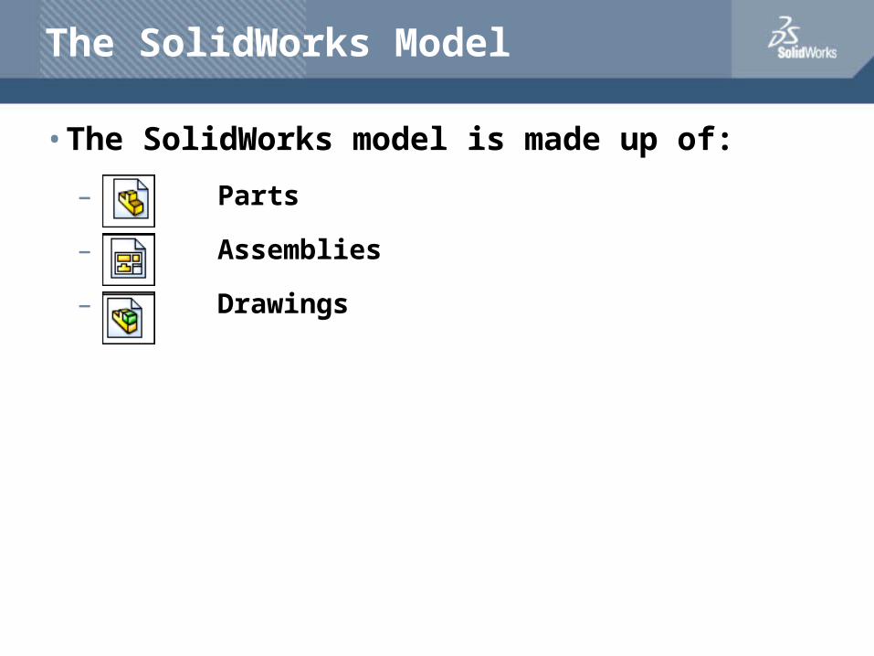
The SolidWorks Model
• The SolidWorks model is made up of:
– Parts
– Assemblies
– Drawings
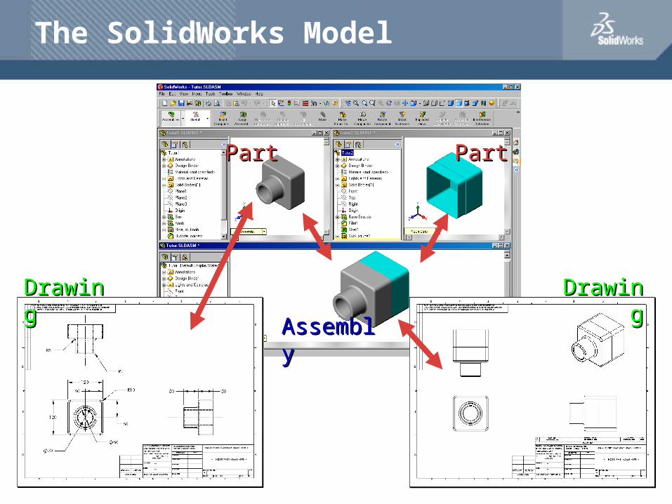
PartPart PartPart
AssemblyAssembly
DrawingDrawing DrawingDrawing
The SolidWorks Model
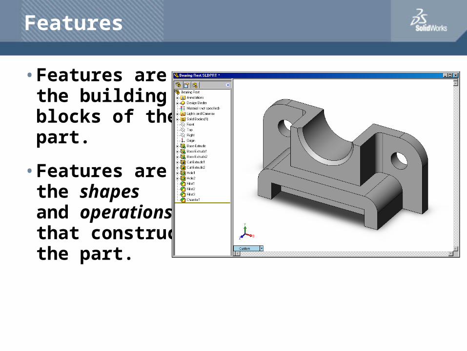
Features
• Features are the building blocks of the part.
• Features are the shapes and operations that construct the part.
Examples of Shape Features
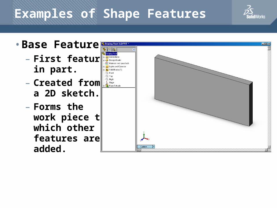
• Base Feature– First feature
in part.
– Created from a 2D sketch.
– Forms the work piece to which other features are added.
Examples of Shape Features
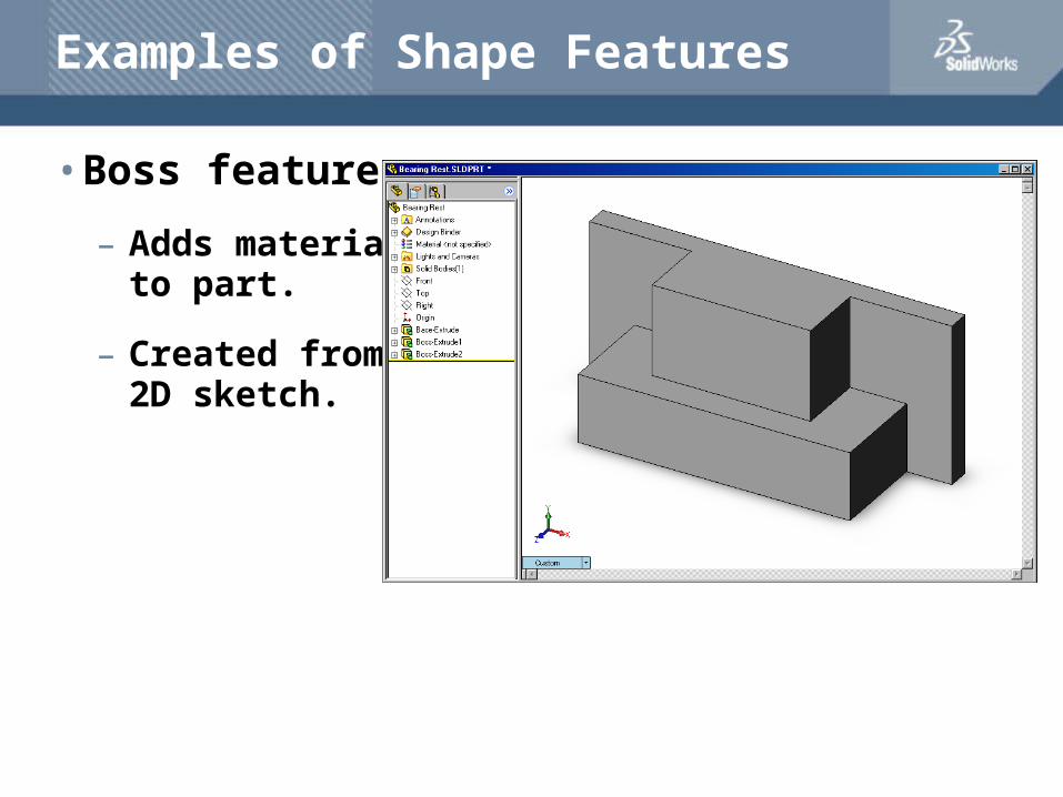
• Boss feature
– Adds material to part.
– Created from 2D sketch.
Examples of Shape Features
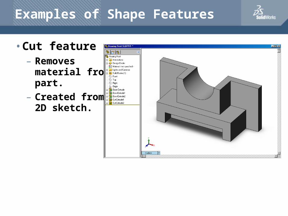
• Cut feature– Removes
material from part.
– Created from 2D sketch.
Examples of Shape Features
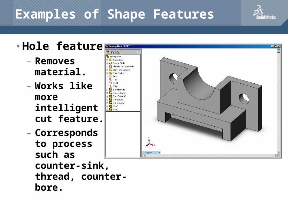
• Hole feature– Removes
material.
– Works like more intelligent cut feature.
– Corresponds to process such as counter-sink, thread, counter-bore.
Examples of Shape Features
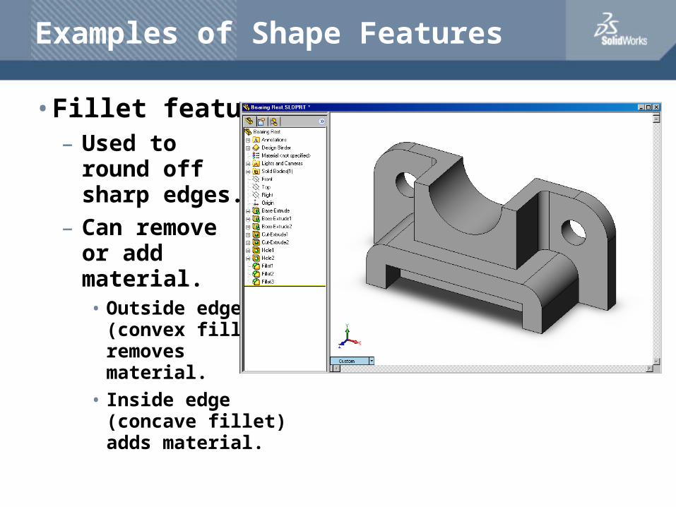
• Fillet feature– Used to
round off sharp edges.
– Can remove or add material.• Outside edge
(convex fillet) removes material.
• Inside edge (concave fillet) adds material.
Examples of Shape Features
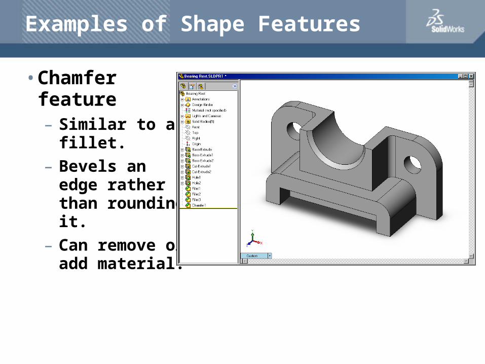
• Chamfer feature– Similar to a
fillet.
– Bevels an edge rather than rounding it.
– Can remove or add material.
Sketched Features & Operation Features
• Sketched Features– Shape features have sketches.
– Sketched features are built from 2D profiles.
• Operation Features
– Operation features do not have sketches.
– Applied directly to the work piece by selecting edges or faces.
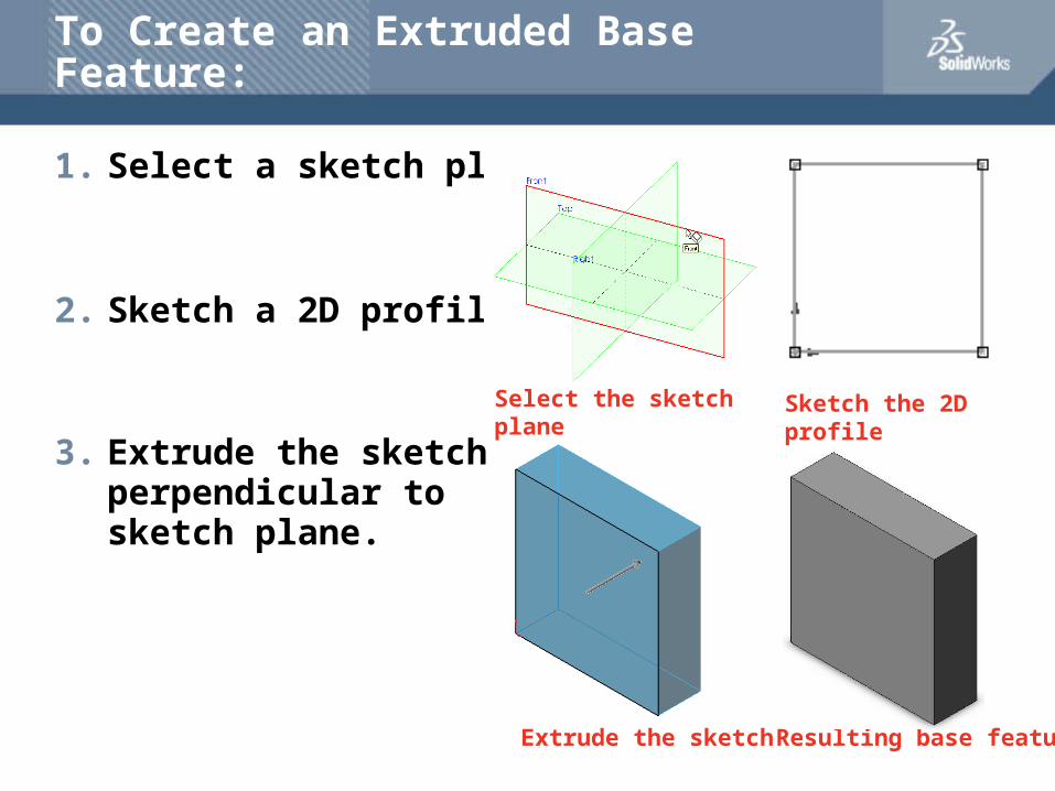
Sketch the 2D profile
Extrude the sketch Resulting base feature
To Create an Extruded Base Feature:
1. Select a sketch plane.
2. Sketch a 2D profile.
3. Extrude the sketch perpendicular to sketch plane.
Select the sketch plane
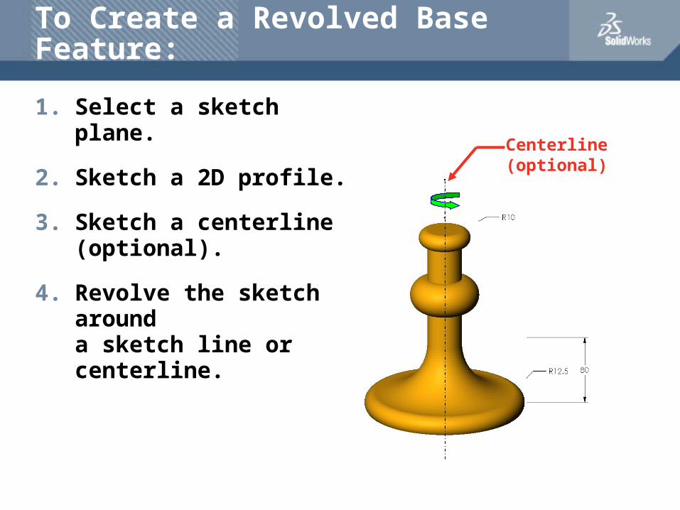
To Create a Revolved Base Feature:
1. Select a sketch plane.
2. Sketch a 2D profile.
3. Sketch a centerline (optional).
4. Revolve the sketch arounda sketch line or centerline.
Centerline (optional)
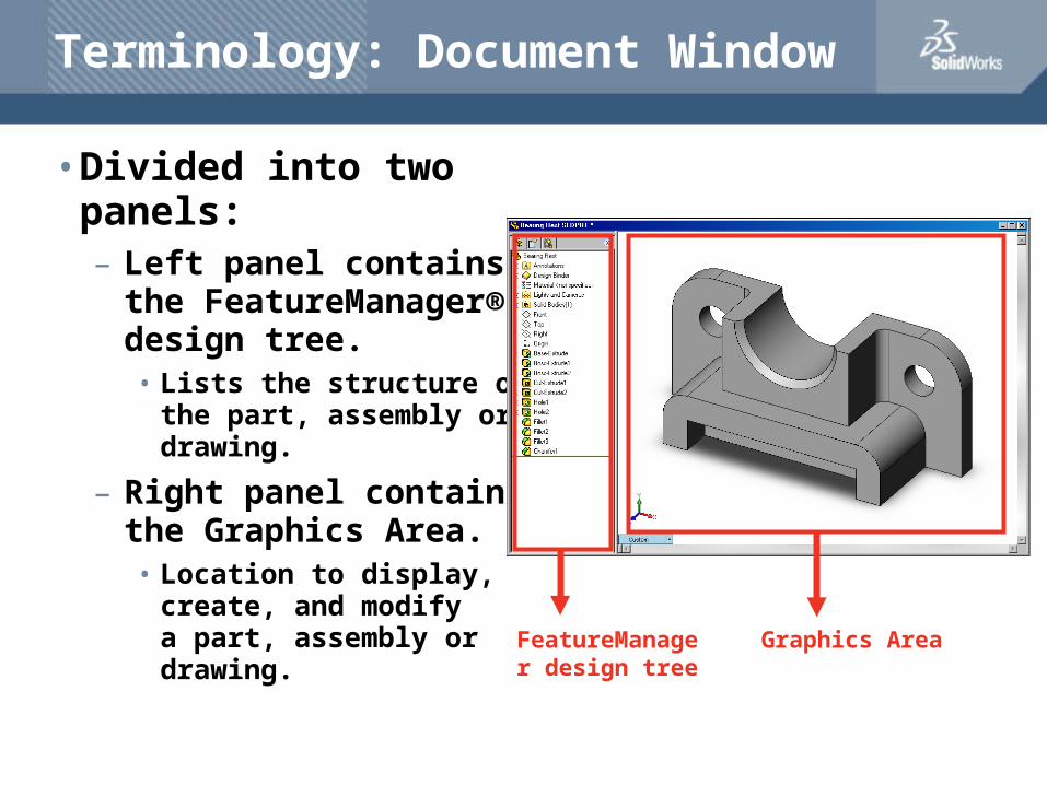
Terminology: Document Window
• Divided into two panels:– Left panel contains
the FeatureManager® design tree.• Lists the structure of
the part, assembly or drawing.
– Right panel contains the Graphics Area.• Location to display,
create, and modify a part, assembly or drawing. FeatureManager
design treeGraphics Area
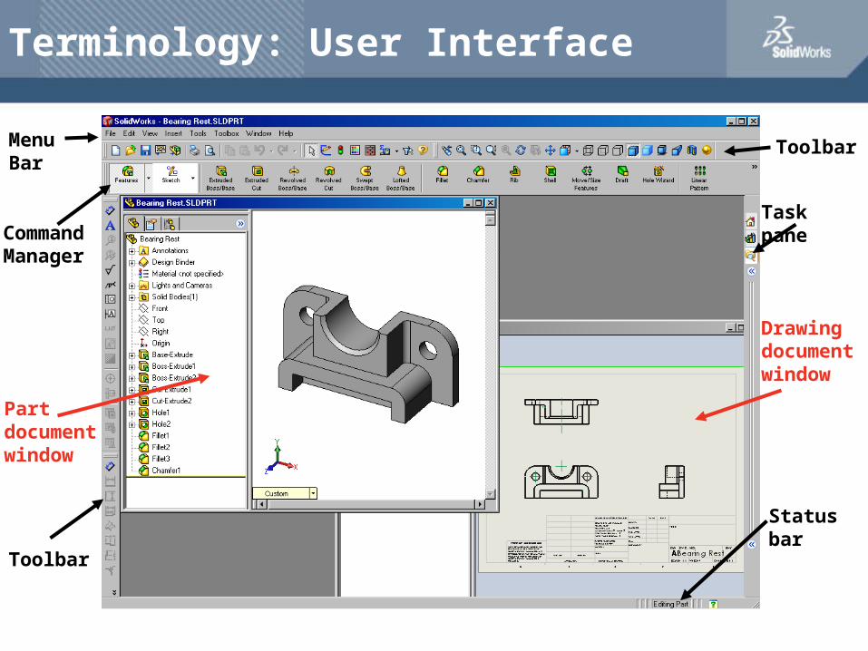
Terminology: User Interface
Toolbar
Toolbar
MenuBar
Task pane
Status bar
CommandManager
Drawingdocumentwindow
Partdocumentwindow
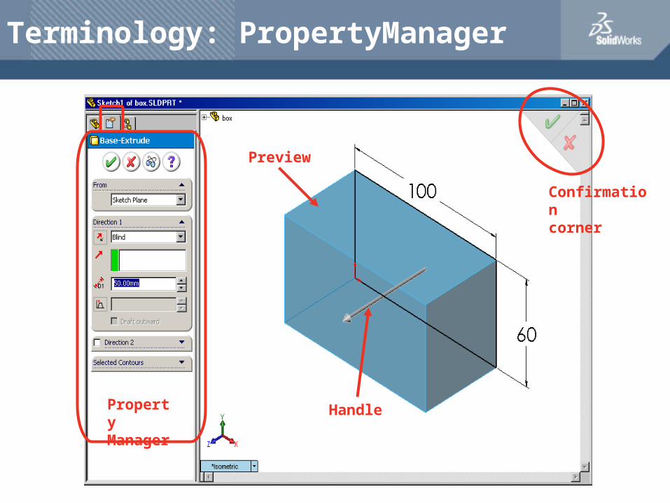
Terminology: PropertyManager
PropertyManager
Confirmationcorner
Preview
Handle
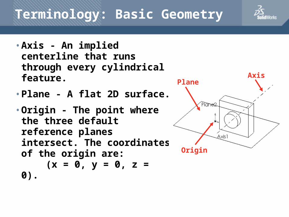
Terminology: Basic Geometry
• Axis - An implied centerline that runs through every cylindrical feature.
• Plane - A flat 2D surface.
• Origin - The point where the three default reference planes intersect. The coordinates of the origin are:
(x = 0, y = 0, z = 0).
AxisPlane
Origin
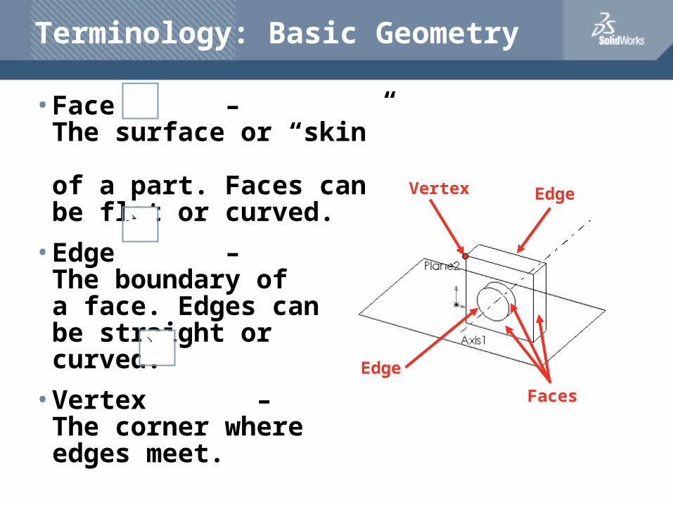
Terminology: Basic Geometry
• Face – The surface or “skin” of a part. Faces can be flat or curved.
• Edge – The boundary of a face. Edges can be straight or curved.
• Vertex – The corner where edges meet.
Vertex
Edge
Edge
Faces

Features and Commands
Base feature
• The Base feature is the first feature that is created.
• The Base feature is the foundation of the part.
• The Base feature geometry for the box is an extrusion.
• The extrusion is named Extrude1.
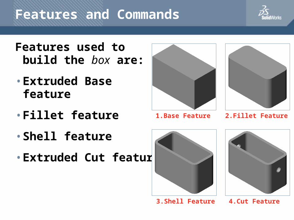
Features and Commands
Features used to build the box are:
• Extruded Base feature
• Fillet feature
• Shell feature
• Extruded Cut feature
1.Base Feature 2.Fillet Feature
3.Shell Feature 4.Cut Feature
Features and Commands
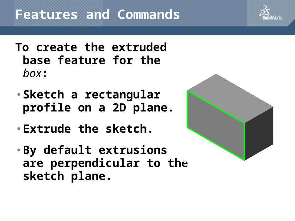
To create the extruded base feature for the box:
• Sketch a rectangular profile on a 2D plane.
• Extrude the sketch.
• By default extrusions are perpendicular to the sketch plane.
Features and Commands
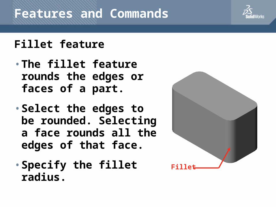
Fillet feature
• The fillet feature rounds the edges or faces of a part.
• Select the edges to be rounded. Selecting a face rounds all the edges of that face.
• Specify the fillet radius. Fillet
Wall Thickness
Features and Commands
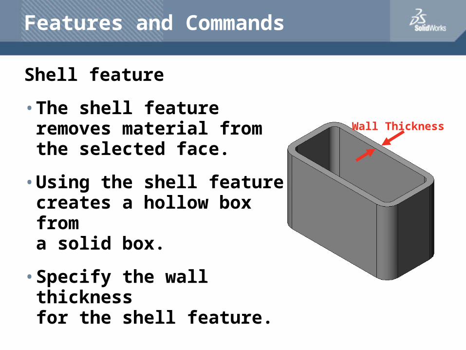
Shell feature
• The shell feature removes material from the selected face.
• Using the shell feature creates a hollow box froma solid box.
• Specify the wall thicknessfor the shell feature.
Features and Commands
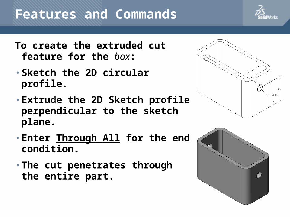
To create the extruded cut feature for the box:
• Sketch the 2D circular profile.
• Extrude the 2D Sketch profile perpendicular to the sketch plane.
• Enter Through All for the end condition.
• The cut penetrates through the entire part.
Dimensions and Geometric Relationships
• Specify dimensions and geometric relationships between features and sketches.
• Dimensions change the size and shape of the part.
• Mathematical relationships between dimensions can be controlled by equations.
• Geometric relationships are the rules that control the behavior of sketch geometry.
• Geometric relationships help capture design intent.
Dimensions
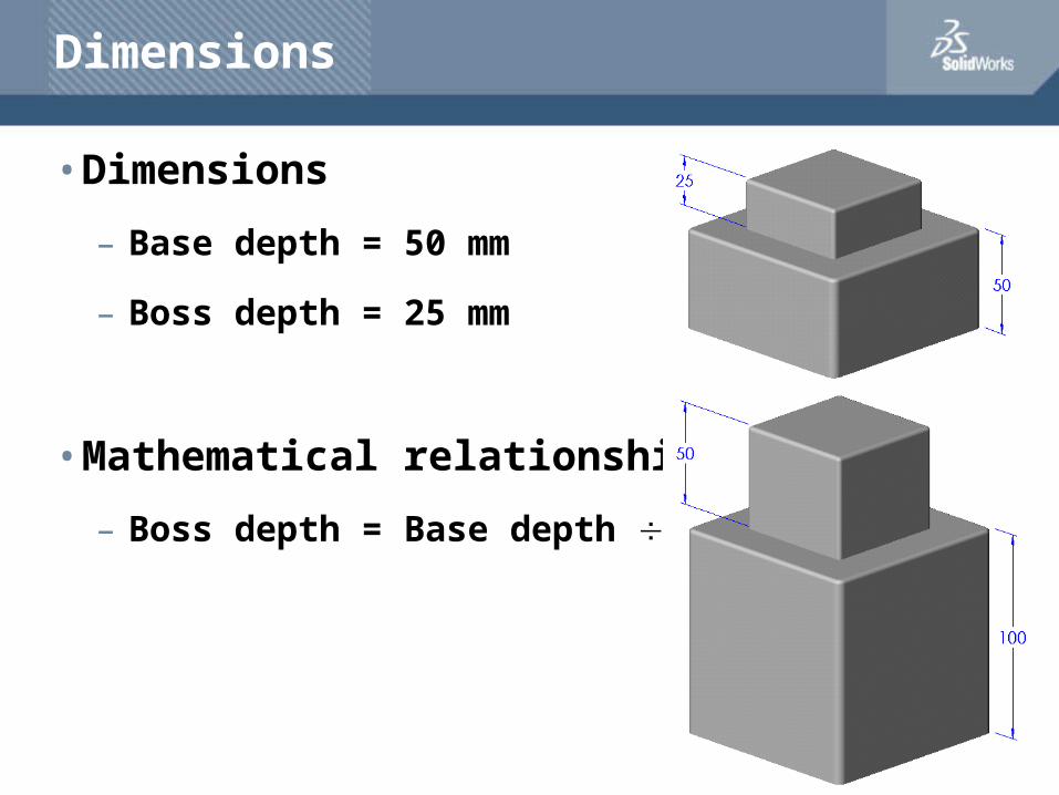
• Dimensions
– Base depth = 50 mm
– Boss depth = 25 mm
• Mathematical relationship
– Boss depth = Base depth 2
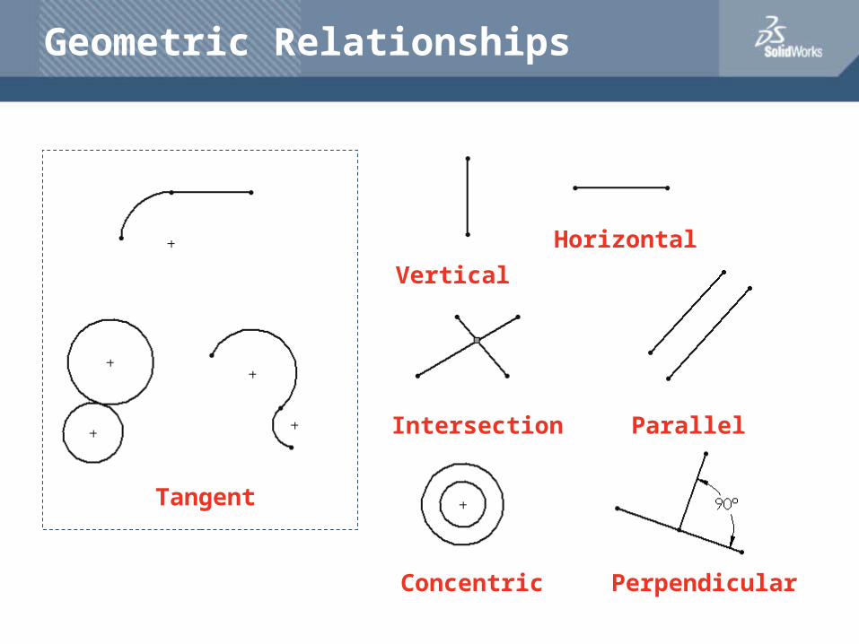
Geometric Relationships
Tangent
Parallel
Horizontal
Vertical
Intersection
Concentric Perpendicular
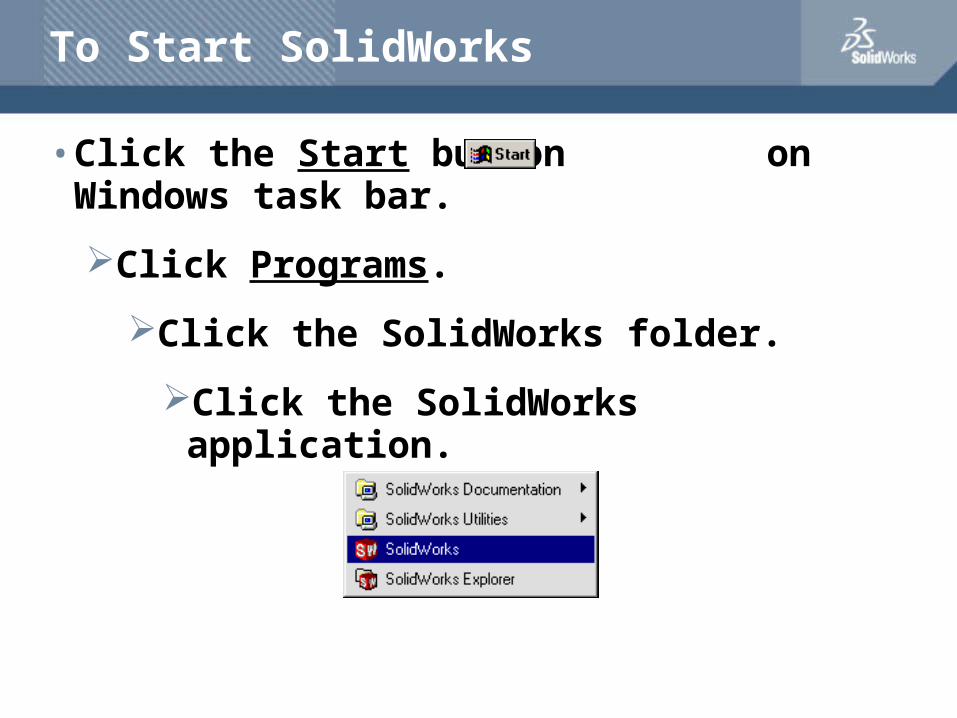
To Start SolidWorks
• Click the Start button on Windows task bar.
Click Programs.
Click the SolidWorks folder.
Click the SolidWorks application.
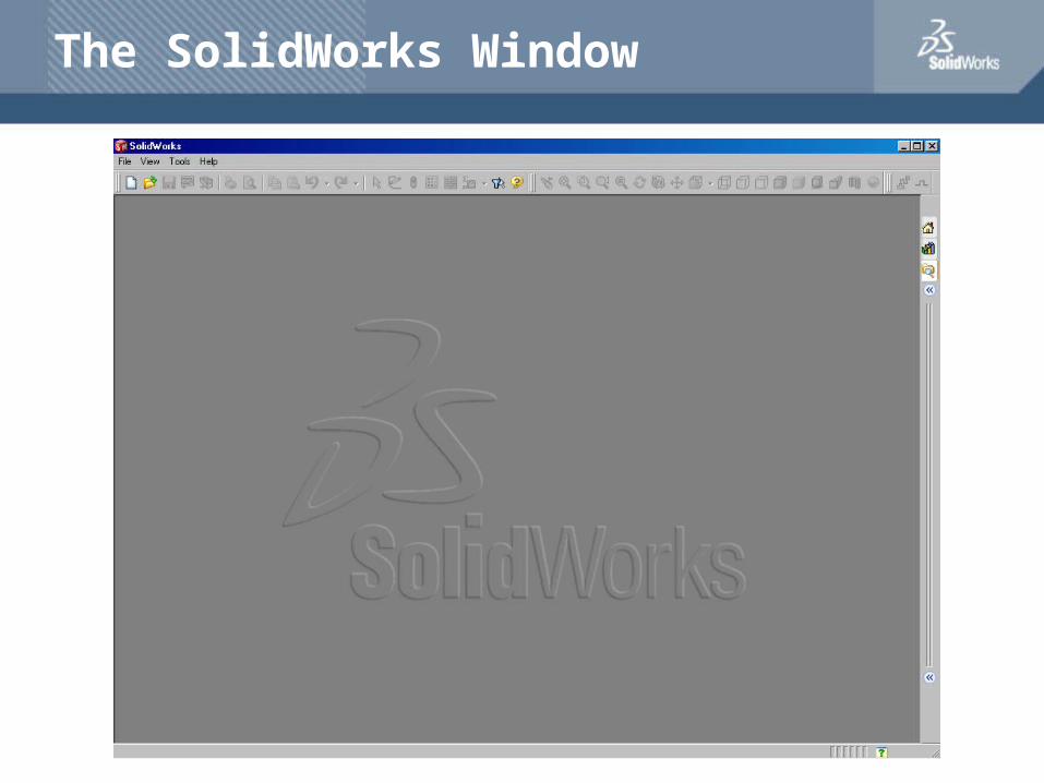
The SolidWorks Window
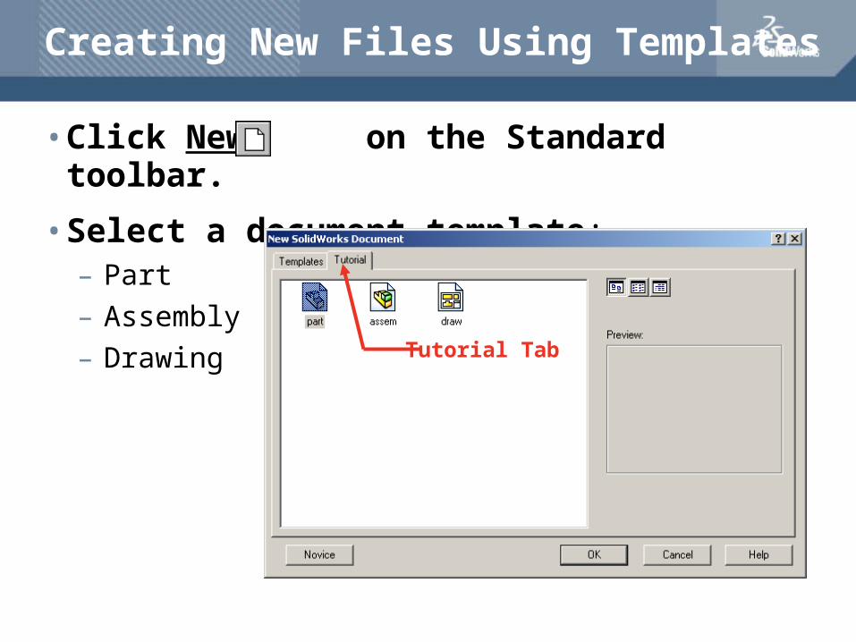
Creating New Files Using Templates
• Click New on the Standard toolbar.
• Select a document template:– Part
– Assembly
– DrawingTutorial Tab
Document Templates
• Document Templates control the units, grid, text, and other settings for the model.
• The Tutorial document templates are required to complete the exercises in the Online Tutorials.
• The templates are located in the Tutorial tab on the New SolidWorks Document dialog box.
• Document properties are saved in templates.
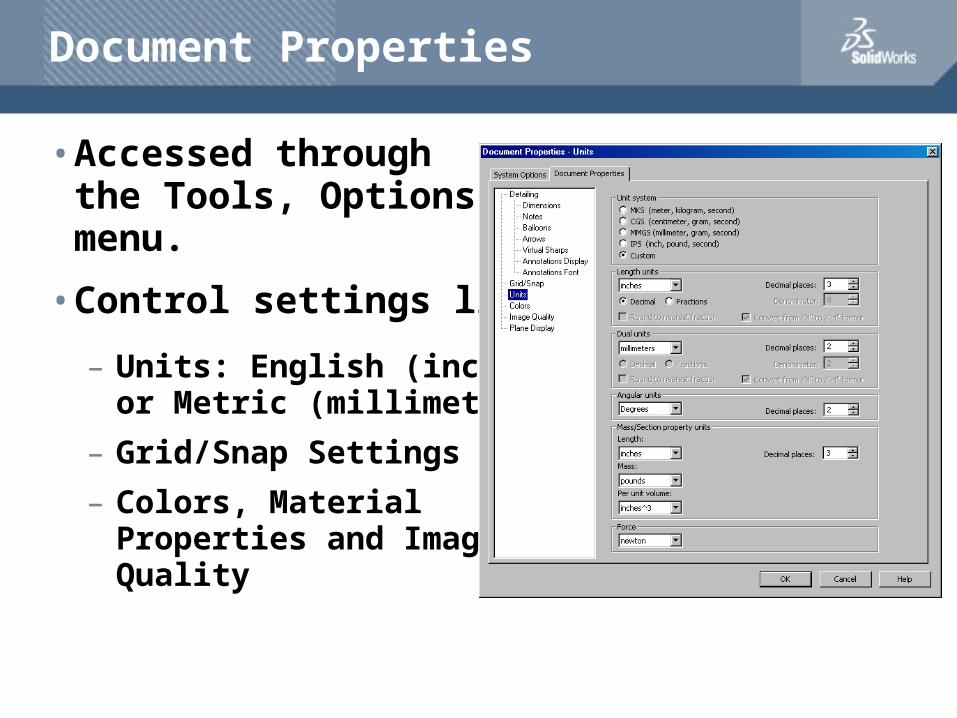
Document Properties
• Accessed through the Tools, Options menu.
• Control settings like:
– Units: English (inches) or Metric (millimeters)
– Grid/Snap Settings
– Colors, Material Properties and Image Quality
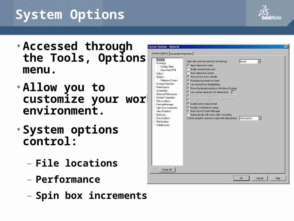
System Options
• Accessed through the Tools, Options menu.
• Allow you to customize your work environment.
• System options control:
– File locations
– Performance
– Spin box increments
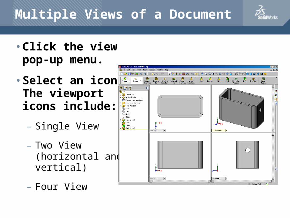
Multiple Views of a Document
• Click the view pop-up menu.
• Select an icon.The viewport icons include:
– Single View
– Two View (horizontal and vertical)
– Four View
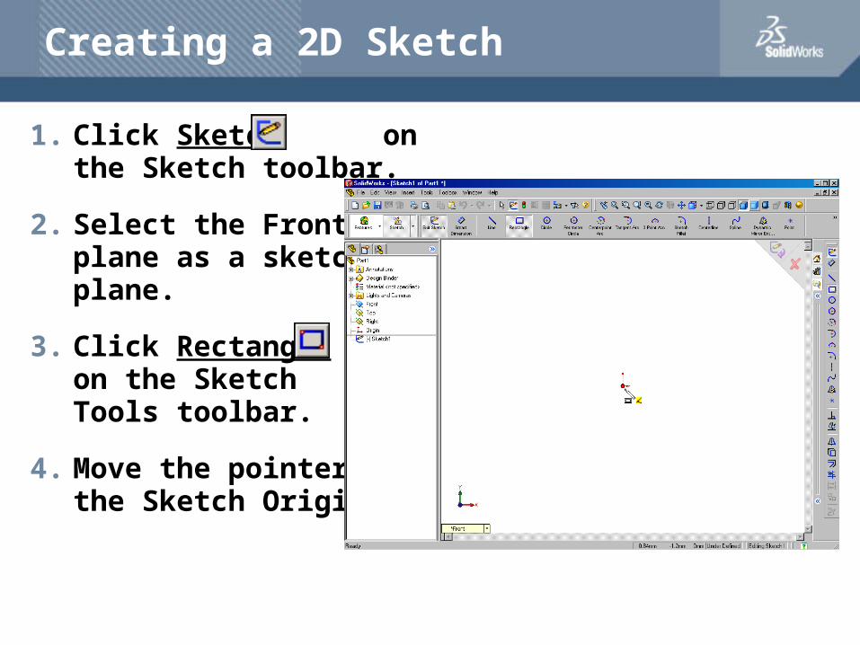
Creating a 2D Sketch
1. Click Sketch on the Sketch toolbar.
2. Select the Front plane as a sketch plane.
3. Click Rectangle on the Sketch Tools toolbar.
4. Move the pointer to the Sketch Origin.
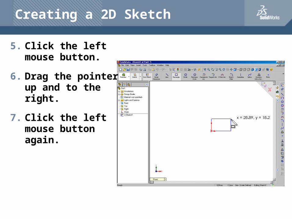
Creating a 2D Sketch
5. Click the left mouse button.
6. Drag the pointer up and to the right.
7. Click the left mouse button again.
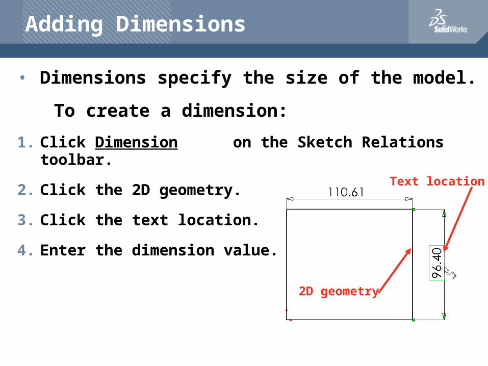
Adding Dimensions
• Dimensions specify the size of the model.
To create a dimension:
1. Click Dimension on the Sketch Relations toolbar.
2. Click the 2D geometry.
3. Click the text location.
4. Enter the dimension value.
2D geometry
Text location