Embed Size (px)
Citation preview
1
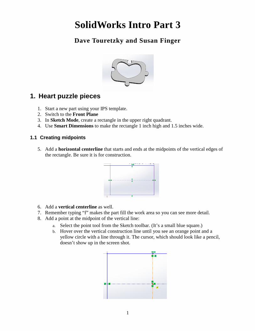
SolidWorks Intro Part 3 Dave Touretzky and Susan Finger
1. Heart puzzle pieces
1. Start a new part using your IPS template. 2. Switch to the Front Plane 3. In Sketch Mode, create a rectangle in the upper right quadrant. 4. Use Smart Dimensions to make the rectangle 1 inch high and 1.5 inches wide.
1.1 Creating midpoints
5. Add a horizontal centerline that starts and ends at the midpoints of the vertical edges of the rectangle. Be sure it is for construction.
6. Add a vertical centerline as well. 7. Remember typing “f” makes the part fill the work area so you can see more detail. 8. Add a point at the midpoint of the vertical line:
a. Select the point tool from the Sketch toolbar. (It’s a small blue square.) b. Hover over the vertical construction line until you see an orange point and a
yellow circle with a line through it. The cursor, which should look like a pencil, doesn’t show up in the screen shot.
2
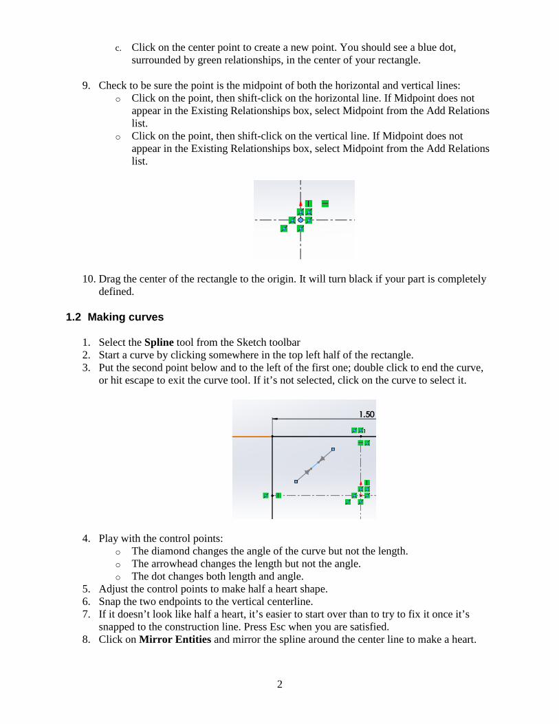
c. Click on the center point to create a new point. You should see a blue dot, surrounded by green relationships, in the center of your rectangle.
9. Check to be sure the point is the midpoint of both the horizontal and vertical lines: o Click on the point, then shift-click on the horizontal line. If Midpoint does not
appear in the Existing Relationships box, select Midpoint from the Add Relations list.
o Click on the point, then shift-click on the vertical line. If Midpoint does not appear in the Existing Relationships box, select Midpoint from the Add Relations list.
10. Drag the center of the rectangle to the origin. It will turn black if your part is completely defined.
1.2 Making curves
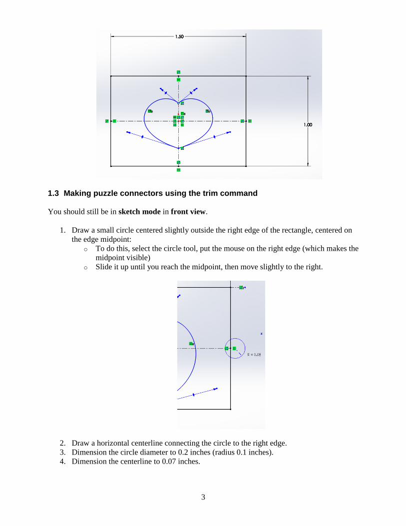
1. Select the Spline tool from the Sketch toolbar 2. Start a curve by clicking somewhere in the top left half of the rectangle. 3. Put the second point below and to the left of the first one; double click to end the curve,
or hit escape to exit the curve tool. If it’s not selected, click on the curve to select it.
4. Play with the control points: o The diamond changes the angle of the curve but not the length. o The arrowhead changes the length but not the angle. o The dot changes both length and angle.
5. Adjust the control points to make half a heart shape. 6. Snap the two endpoints to the vertical centerline. 7. If it doesn’t look like half a heart, it’s easier to start over than to try to fix it once it’s
snapped to the construction line. Press Esc when you are satisfied. 8. Click on Mirror Entities and mirror the spline around the center line to make a heart.
3
1.3 Making puzzle connectors using the trim command
You should still be in sketch mode in front view.
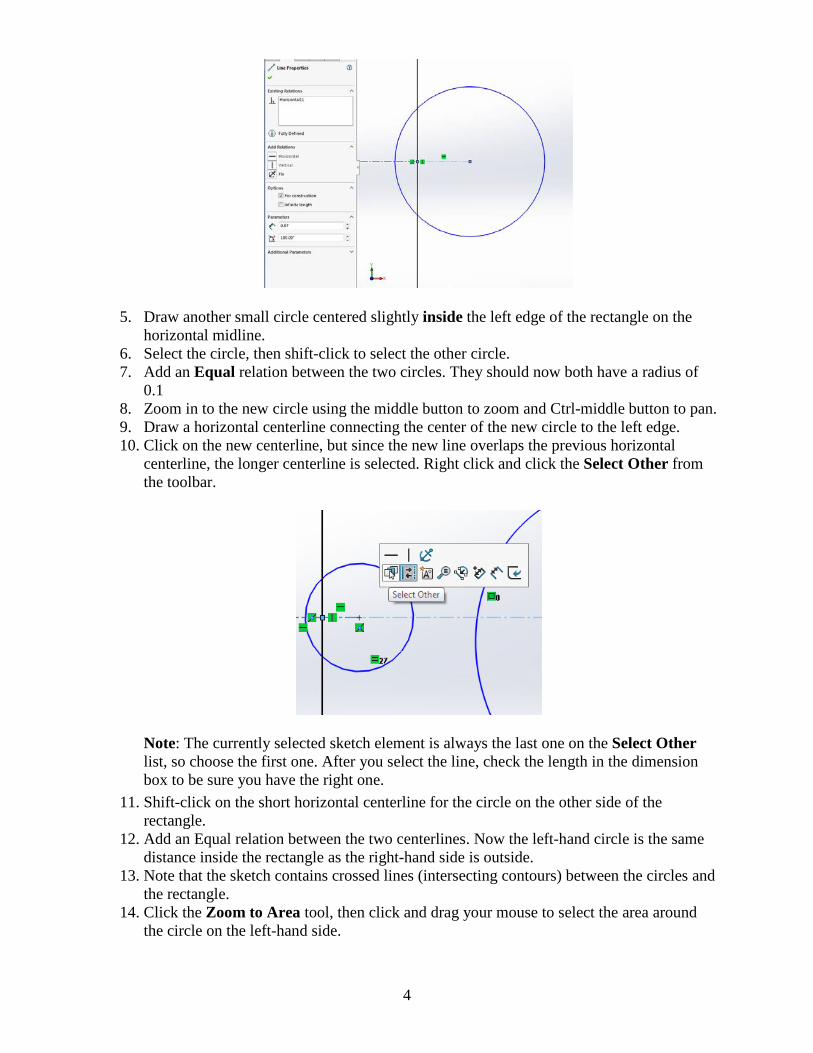
1. Draw a small circle centered slightly outside the right edge of the rectangle, centered on the edge midpoint:
o To do this, select the circle tool, put the mouse on the right edge (which makes the midpoint visible)
o Slide it up until you reach the midpoint, then move slightly to the right.
2. Draw a horizontal centerline connecting the circle to the right edge. 3. Dimension the circle diameter to 0.2 inches (radius 0.1 inches). 4. Dimension the centerline to 0.07 inches.
4
5. Draw another small circle centered slightly inside the left edge of the rectangle on the horizontal midline.
6. Select the circle, then shift-click to select the other circle. 7. Add an Equal relation between the two circles. They should now both have a radius of
0.1 8. Zoom in to the new circle using the middle button to zoom and Ctrl-middle button to pan. 9. Draw a horizontal centerline connecting the center of the new circle to the left edge. 10. Click on the new centerline, but since the new line overlaps the previous horizontal
centerline, the longer centerline is selected. Right click and click the Select Other from the toolbar.
Note: The currently selected sketch element is always the last one on the Select Other list, so choose the first one. After you select the line, check the length in the dimension box to be sure you have the right one.
11. Shift-click on the short horizontal centerline for the circle on the other side of the rectangle.
12. Add an Equal relation between the two centerlines. Now the left-hand circle is the same distance inside the rectangle as the right-hand side is outside.
13. Note that the sketch contains crossed lines (intersecting contours) between the circles and the rectangle.
14. Click the Zoom to Area tool, then click and drag your mouse to select the area around the circle on the left-hand side.
5
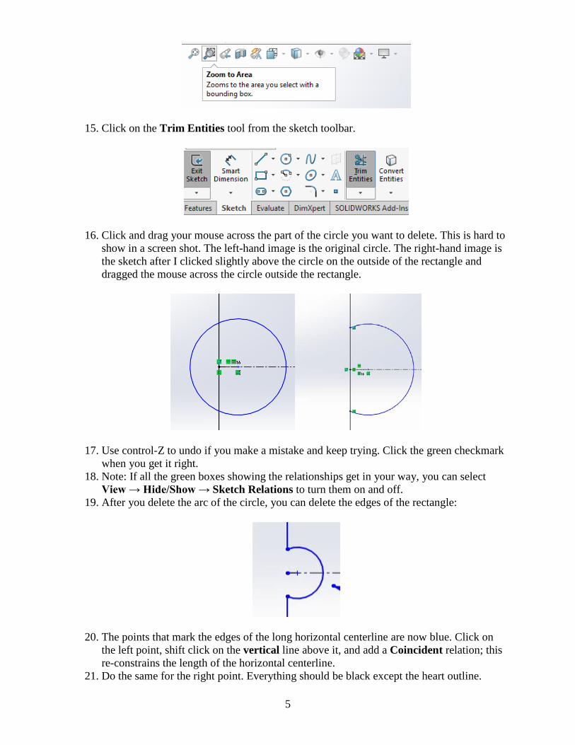
15. Click on the Trim Entities tool from the sketch toolbar.
16. Click and drag your mouse across the part of the circle you want to delete. This is hard to show in a screen shot. The left-hand image is the original circle. The right-hand image is the sketch after I clicked slightly above the circle on the outside of the rectangle and dragged the mouse across the circle outside the rectangle.
17. Use control-Z to undo if you make a mistake and keep trying. Click the green checkmark when you get it right.
18. Note: If all the green boxes showing the relationships get in your way, you can select View → Hide/Show → Sketch Relations to turn them on and off.
19. After you delete the arc of the circle, you can delete the edges of the rectangle:
20. The points that mark the edges of the long horizontal centerline are now blue. Click on the left point, shift click on the vertical line above it, and add a Coincident relation; this re-constrains the length of the horizontal centerline.
21. Do the same for the right point. Everything should be black except the heart outline.
6
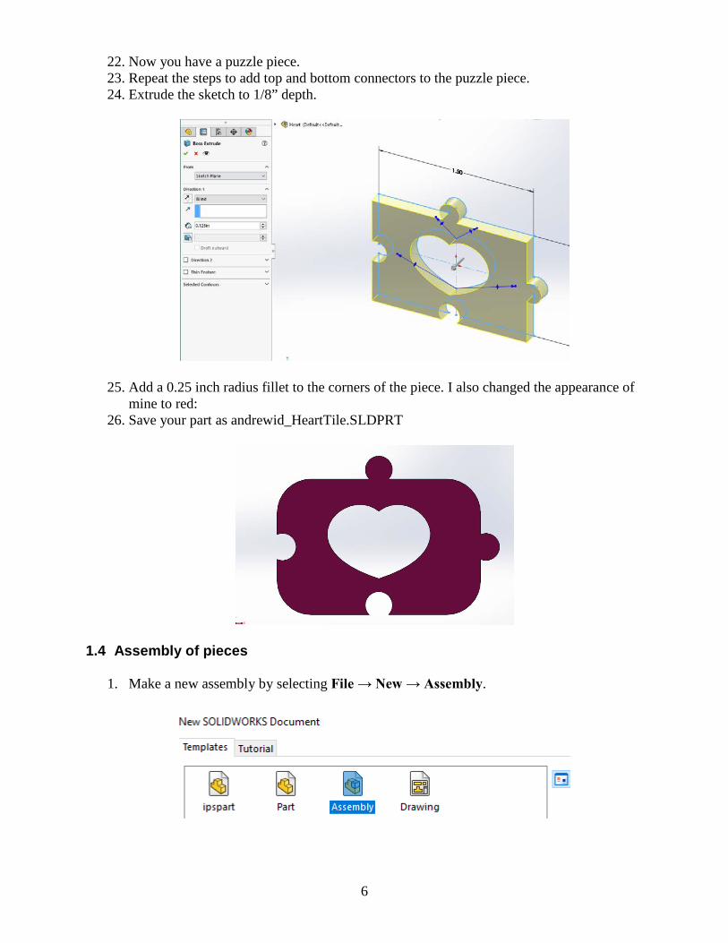
22. Now you have a puzzle piece. 23. Repeat the steps to add top and bottom connectors to the puzzle piece. 24. Extrude the sketch to 1/8” depth.
25. Add a 0.25 inch radius fillet to the corners of the piece. I also changed the appearance of mine to red:
26. Save your part as andrewid_HeartTile.SLDPRT
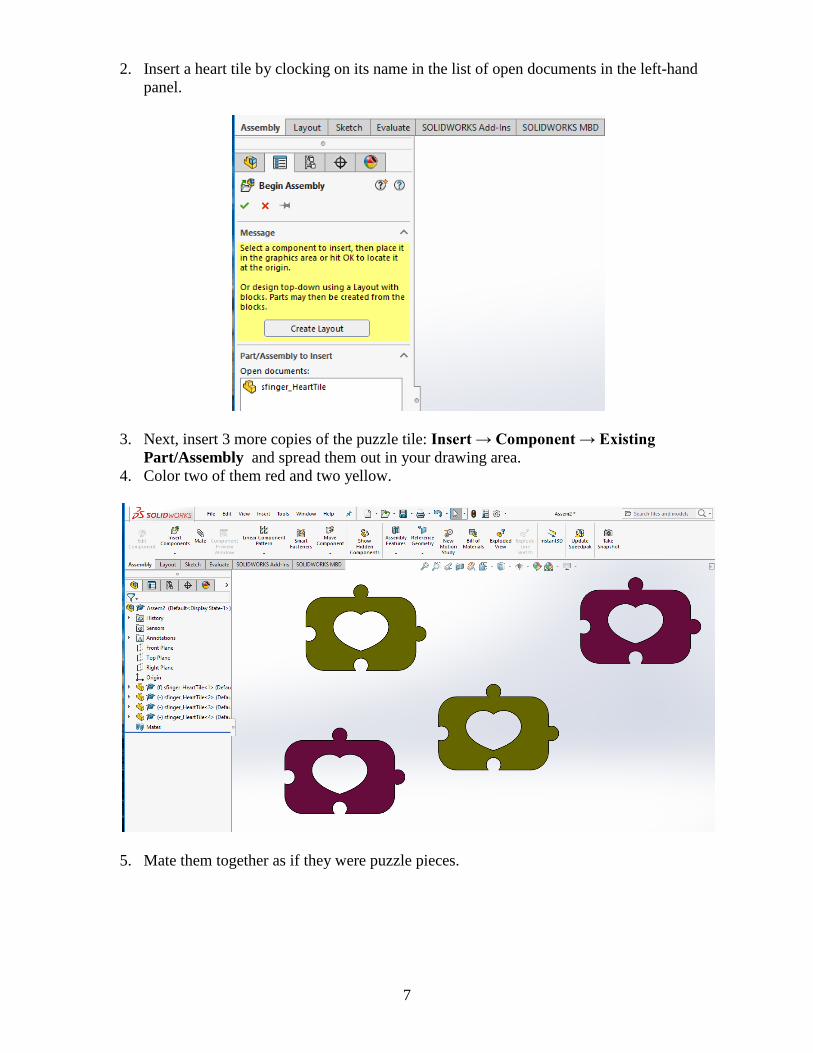
1.4 Assembly of pieces
1. Make a new assembly by selecting File → New → Assembly.
7
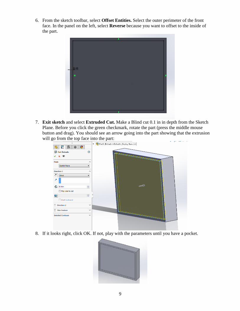
2. Insert a heart tile by clocking on its name in the list of open documents in the left-hand panel.
3. Next, insert 3 more copies of the puzzle tile: Insert → Component → Existing Part/Assembly and spread them out in your drawing area.
4. Color two of them red and two yellow.
5. Mate them together as if they were puzzle pieces.

8
6. Save your assembly as andrewid_HeartMosaic.SLDASM
1.5 Offsetting curves In the next section, you will offset the puzzle pieces to account for the width of the laser beam, but the offsets are so small (the laser beam is so small) that it is difficult to see what is going on. This section uses the offset command to create a pocket and a slot.
1. Start a new part: File → New → Templates → IPSpart. 2. Start a sketch and create a rectangle in front view. The dimensions don’t matter.
3. Exit the sketch and extrude the rectangle to a depth of 0.6 inches. 4. Go back to the front view and right click on the face that is closest to you. Next, we will
make a pocket on the top face. (If you don’t know what a machined pocket looks like, look at the screen shot on the next page.
5. Select Sketch from the popup toolbar. Note: You are not editing the existing sketch. You are starting a new sketch on the top face of the part.
9
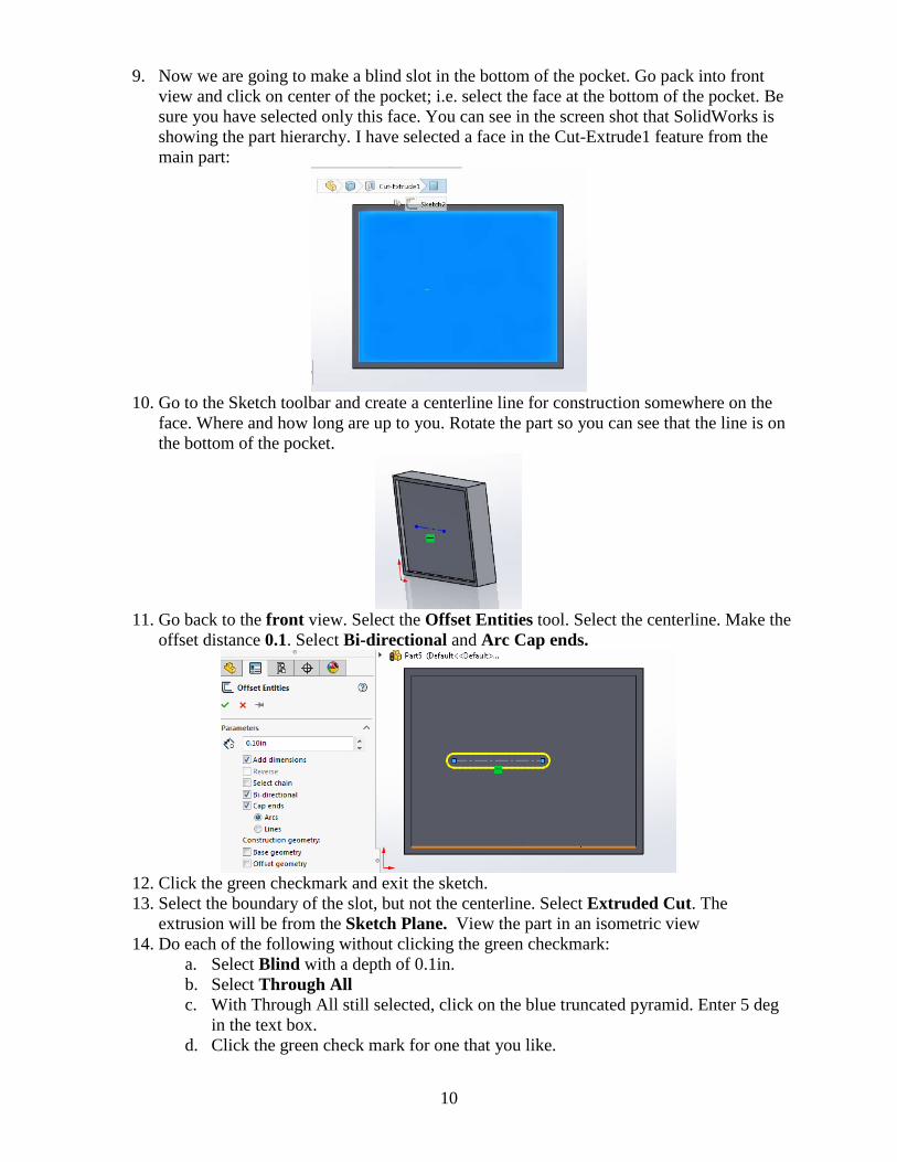
6. From the sketch toolbar, select Offset Entities. Select the outer perimeter of the front face. In the panel on the left, select Reverse because you want to offset to the inside of the part.
7. Exit sketch and select Extruded Cut. Make a Blind cut 0.1 in in depth from the Sketch
Plane. Before you click the green checkmark, rotate the part (press the middle mouse button and drag). You should see an arrow going into the part showing that the extrusion will go from the top face into the part:
8. If it looks right, click OK. If not, play with the parameters until you have a pocket.
10
9. Now we are going to make a blind slot in the bottom of the pocket. Go pack into front view and click on center of the pocket; i.e. select the face at the bottom of the pocket. Be sure you have selected only this face. You can see in the screen shot that SolidWorks is showing the part hierarchy. I have selected a face in the Cut-Extrude1 feature from the main part:
10. Go to the Sketch toolbar and create a centerline line for construction somewhere on the
face. Where and how long are up to you. Rotate the part so you can see that the line is on the bottom of the pocket.
11. Go back to the front view. Select the Offset Entities tool. Select the centerline. Make the
offset distance 0.1. Select Bi-directional and Arc Cap ends.
12. Click the green checkmark and exit the sketch. 13. Select the boundary of the slot, but not the centerline. Select Extruded Cut. The
extrusion will be from the Sketch Plane. View the part in an isometric view 14. Do each of the following without clicking the green checkmark:
a. Select Blind with a depth of 0.1in. b. Select Through All c. With Through All still selected, click on the blue truncated pyramid. Enter 5 deg
in the text box. d. Click the green check mark for one that you like.
11
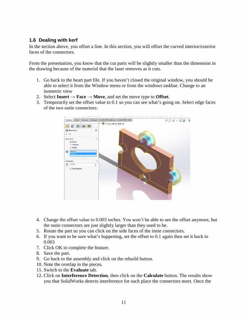
1.6 Dealing with kerf In the section above, you offset a line. In this section, you will offset the curved interior/exterior faces of the connectors. From the presentation, you know that the cut parts will be slightly smaller than the dimension in the drawing because of the material that the laser removes as it cuts.
1. Go back to the heart part file. If you haven’t closed the original window, you should be able to select it from the Window menu or from the windows taskbar. Change to an isometric view
2. Select Insert → Face → Move, and set the move type to Offset. 3. Temporarily set the offset value to 0.1 so you can see what’s going on. Select edge faces
of the two outie connectors:
4. Change the offset value to 0.003 inches. You won’t be able to see the offset anymore, but the outie connectors are just slightly larger than they used to be.
5. Rotate the part so you can click on the side faces of the innie connectors. 6. If you want to be sure what’s happening, set the offset to 0.1 again then set it back to
0.003 7. Click OK to complete the feature. 8. Save the part. 9. Go back to the assembly and click on the rebuild button. 10. Note the overlap in the pieces. 11. Switch to the Evaluate tab. 12. Click on Interference Detection, then click on the Calculate button. The results show
you that SolidWorks detects interference for each place the connectors meet. Once the

12
parts are laser cut, the interference will go away because this overlap is the width of the laser beam.
13. Save your files.
1.7 Create a DXF file to send to the laser cutter
Finally, create a SolidWorks drawing so that you can create a single DXF file that cuts all four of your tiles (but not in the mated configuration.). Email the dxf file [email protected] and post a picture of your assembled puzzle on piazza.