Embed Size (px)
Citation preview

SolidWorks 2001PlusWhat’s New
© 1995-2001, SolidWorks Corporation 300 Baker AvenueConcord, Massachusetts 01742 USAAll Rights Reserved.
SolidWorks Corporation is a Dassault Systemes S.A. (Nasdaq:DASTY) company.The information and the software discussed in this document are subject to change without notice and should not be considered commitments by SolidWorks Corporation. No material may be reproduced or transmitted in any form or by any means, electronic or mechanical, for any purpose without the express written permission of SolidWorks Corporation.As a condition to your use of this software product, you agree to accept the limited warranty, disclaimer and other terms and conditions set forth in the SolidWorks Corporation License and Subscription Service Agreement, which accompanies this software. If, after reading the License Agreement, you do not agree with the limited warranty, the disclaimer or any of the other terms and conditions, promptly return the unused software and all accompanying documentation to SolidWorks Corporation and your money will be refunded.The software discussed in this document is furnished under a license and may be used or copied only in accordance with the terms of this license. All warranties given by SolidWorks Corporation as to the software and documentation are set forth in the SolidWorks Corporation License and Subscription Service Agreement, and nothing stated in, or implied by, this document or its contents shall be considered or deemed a modification or amendment of such warranties. SolidWorks® is a registered trademark of SolidWorks Corporation.SolidWorks 2001Plus is a product name of SolidWorks Corporation.FeatureManager® is a jointly owned registered trademark of SolidWorks Corporation.Feature Palette™ and PhotoWorks™ are trademarks of SolidWorks Corporation.
ACIS® is a registered trademark of Spatial Technology Inc.IGES Access Library is a trademark of IGES Data Analysis, Inc. FeatureWorks® is a registered trademark of Geometric Software Solutions Co. Limited.GLOBEtrotter® and FLEXlm® are registered trademarks of Globetrotter Software, Inc.Other brand or product names are trademarks or registered trademarks of their respective holders.
COMMERCIAL COMPUTER SOFTWARE - PROPRIETARYU.S. Government Restricted Rights. Use, duplication or disclosure by the Government is subject to restrictions as set forth in FAR 52.227-19 (Commercial Computer Software - Restricted Rights), DFARS 252.227-7202(Commercial Computer Software and Commercial Computer Software Documentation) and in the license agreement, as applicable. Contractor/Manufacturer: SolidWorks Corporation, 300 Baker Avenue, Concord, Massachusetts 01742 USAPortions of this software are copyrighted by and are the property of Unigraphics Solutions Inc.Portions of this software © 1990-2001 D-Cubed Limited.Portions of this software © 1998-2001 Geometric Software Solutions Co. Limited.Portions of this software © 1999-2001 Immersive Design, Inc.Portions of this software © 1990-2001 LightWork Design Limited.Portions of this software © 1996 Microsoft Corporation. All Rights Reserved.Portions of this software © 1995-2001 Spatial CorporationPortions of this software © 1999-2001 Viewpoint CorporationPortions of this software © 1997-2001 Virtue 3D, Inc.All Rights Reserved.
U.S. Patents 5,815,154, 6,219,049, 6,219,055
Document Number: SWXWNENG091501
Contents
IntroductionAbout This Book. . . . . . . . . . . . . . . . . . . . . . . . . . . . . . . . . . . . . . . . . . . . . . . . . . . . . ixMoving to SolidWorks 2001Plus . . . . . . . . . . . . . . . . . . . . . . . . . . . . . . . . . . . . . . . . . x
Chapter 1 SolidWorks FundamentalsUnits of Measure. . . . . . . . . . . . . . . . . . . . . . . . . . . . . . . . . . . . . . . . . . . . . . . . . . . . 1-2Planes and Axes . . . . . . . . . . . . . . . . . . . . . . . . . . . . . . . . . . . . . . . . . . . . . . . . . . . . 1-2
Shaded Planes . . . . . . . . . . . . . . . . . . . . . . . . . . . . . . . . . . . . . . . . . . . . . . . . . . . 1-2Autosize. . . . . . . . . . . . . . . . . . . . . . . . . . . . . . . . . . . . . . . . . . . . . . . . . . . . . . . . 1-3
Shortcut Menus . . . . . . . . . . . . . . . . . . . . . . . . . . . . . . . . . . . . . . . . . . . . . . . . . . . . . 1-3Open Drawing . . . . . . . . . . . . . . . . . . . . . . . . . . . . . . . . . . . . . . . . . . . . . . . . . . . 1-3Rollback. . . . . . . . . . . . . . . . . . . . . . . . . . . . . . . . . . . . . . . . . . . . . . . . . . . . . . . . 1-3Select Chain. . . . . . . . . . . . . . . . . . . . . . . . . . . . . . . . . . . . . . . . . . . . . . . . . . . . . 1-4Delete Face . . . . . . . . . . . . . . . . . . . . . . . . . . . . . . . . . . . . . . . . . . . . . . . . . . . . . 1-4Delete. . . . . . . . . . . . . . . . . . . . . . . . . . . . . . . . . . . . . . . . . . . . . . . . . . . . . . . . . . 1-4
Printing . . . . . . . . . . . . . . . . . . . . . . . . . . . . . . . . . . . . . . . . . . . . . . . . . . . . . . . . . . . 1-4Document Options. . . . . . . . . . . . . . . . . . . . . . . . . . . . . . . . . . . . . . . . . . . . . . . . 1-4System Options . . . . . . . . . . . . . . . . . . . . . . . . . . . . . . . . . . . . . . . . . . . . . . . . . . 1-5Drawings . . . . . . . . . . . . . . . . . . . . . . . . . . . . . . . . . . . . . . . . . . . . . . . . . . . . . . . 1-6
Macros . . . . . . . . . . . . . . . . . . . . . . . . . . . . . . . . . . . . . . . . . . . . . . . . . . . . . . . . . . . 1-7Display . . . . . . . . . . . . . . . . . . . . . . . . . . . . . . . . . . . . . . . . . . . . . . . . . . . . . . . . . . . 1-7
Transparency in Assemblies . . . . . . . . . . . . . . . . . . . . . . . . . . . . . . . . . . . . . . . . 1-7Shadows. . . . . . . . . . . . . . . . . . . . . . . . . . . . . . . . . . . . . . . . . . . . . . . . . . . . . . . . 1-7Zebra Stripes . . . . . . . . . . . . . . . . . . . . . . . . . . . . . . . . . . . . . . . . . . . . . . . . . . . . 1-8Anti-Alias Edge Display . . . . . . . . . . . . . . . . . . . . . . . . . . . . . . . . . . . . . . . . . . . 1-8
SolidWorks 2001Plus What’s New iii
Display HLR Edges in Shaded Mode Color . . . . . . . . . . . . . . . . . . . . . . . . . . . . 1-9Show/Hide Curves, Sketches, and Annotations. . . . . . . . . . . . . . . . . . . . . . . . . . 1-9Using the Middle Mouse Wheel to Zoom . . . . . . . . . . . . . . . . . . . . . . . . . . . . . . 1-9Remove Detail During Zoom/Pan/Rotate . . . . . . . . . . . . . . . . . . . . . . . . . . . . . 1-10Drawings . . . . . . . . . . . . . . . . . . . . . . . . . . . . . . . . . . . . . . . . . . . . . . . . . . . . . . 1-10
Library Features . . . . . . . . . . . . . . . . . . . . . . . . . . . . . . . . . . . . . . . . . . . . . . . . . . . 1-10Toolbars . . . . . . . . . . . . . . . . . . . . . . . . . . . . . . . . . . . . . . . . . . . . . . . . . . . . . . . . . . 1-10PropertyManager. . . . . . . . . . . . . . . . . . . . . . . . . . . . . . . . . . . . . . . . . . . . . . . . . . . 1-11
Chapter 2 SketchingUser Interface Enhancements in Sketching. . . . . . . . . . . . . . . . . . . . . . . . . . . . . . . . 2-2
Edit Sketch Plane . . . . . . . . . . . . . . . . . . . . . . . . . . . . . . . . . . . . . . . . . . . . . . . . . 2-2Sketch Fillet . . . . . . . . . . . . . . . . . . . . . . . . . . . . . . . . . . . . . . . . . . . . . . . . . . . . . 2-3Add Relations. . . . . . . . . . . . . . . . . . . . . . . . . . . . . . . . . . . . . . . . . . . . . . . . . . . . 2-3Display/Delete Relations . . . . . . . . . . . . . . . . . . . . . . . . . . . . . . . . . . . . . . . . . . . 2-4
Override Dims on Drag with Move/Copy. . . . . . . . . . . . . . . . . . . . . . . . . . . . . . . . . 2-5New Routing Toolbar . . . . . . . . . . . . . . . . . . . . . . . . . . . . . . . . . . . . . . . . . . . . . . . . 2-6
Route Line . . . . . . . . . . . . . . . . . . . . . . . . . . . . . . . . . . . . . . . . . . . . . . . . . . . . . . 2-6Jog Line . . . . . . . . . . . . . . . . . . . . . . . . . . . . . . . . . . . . . . . . . . . . . . . . . . . . . . . . 2-6
Pictures on Sketch Planes . . . . . . . . . . . . . . . . . . . . . . . . . . . . . . . . . . . . . . . . . . . . . 2-7Sketch Text on Curves. . . . . . . . . . . . . . . . . . . . . . . . . . . . . . . . . . . . . . . . . . . . . . . . 2-8Inspect Curvature . . . . . . . . . . . . . . . . . . . . . . . . . . . . . . . . . . . . . . . . . . . . . . . . . . . 2-93D Sketching Relations. . . . . . . . . . . . . . . . . . . . . . . . . . . . . . . . . . . . . . . . . . . . . . 2-10Enhancements to Splines. . . . . . . . . . . . . . . . . . . . . . . . . . . . . . . . . . . . . . . . . . . . . 2-10
Simplify Spline . . . . . . . . . . . . . . . . . . . . . . . . . . . . . . . . . . . . . . . . . . . . . . . . . 2-10Two-Point Spline with Tangency. . . . . . . . . . . . . . . . . . . . . . . . . . . . . . . . . . . . 2-11
Chapter 3 2D to 3D ConversionIntroduction . . . . . . . . . . . . . . . . . . . . . . . . . . . . . . . . . . . . . . . . . . . . . . . . . . . . . . . . 3-2Sketch Tools . . . . . . . . . . . . . . . . . . . . . . . . . . . . . . . . . . . . . . . . . . . . . . . . . . . . . . . 3-2
Select Chain . . . . . . . . . . . . . . . . . . . . . . . . . . . . . . . . . . . . . . . . . . . . . . . . . . . . . 3-2Repair Sketch . . . . . . . . . . . . . . . . . . . . . . . . . . . . . . . . . . . . . . . . . . . . . . . . . . . . 3-3Create New Sketch. . . . . . . . . . . . . . . . . . . . . . . . . . . . . . . . . . . . . . . . . . . . . . . . 3-3Extrude and Cut on the 2D to 3D Toolbar . . . . . . . . . . . . . . . . . . . . . . . . . . . . . . 3-4
Converting a 2D Drawing to a 3D Part . . . . . . . . . . . . . . . . . . . . . . . . . . . . . . . . . . . 3-5Extracting Sketches . . . . . . . . . . . . . . . . . . . . . . . . . . . . . . . . . . . . . . . . . . . . . . . . . . 3-6Aligning Sketches . . . . . . . . . . . . . . . . . . . . . . . . . . . . . . . . . . . . . . . . . . . . . . . . . . . 3-7
iv
Extruding a Base Feature . . . . . . . . . . . . . . . . . . . . . . . . . . . . . . . . . . . . . . . . . . . . . .3-8Cutting Features . . . . . . . . . . . . . . . . . . . . . . . . . . . . . . . . . . . . . . . . . . . . . . . . . . . . .3-9
Chapter 4 Reference GeometryPlanes . . . . . . . . . . . . . . . . . . . . . . . . . . . . . . . . . . . . . . . . . . . . . . . . . . . . . . . . . . . . .4-2
Plane Creation. . . . . . . . . . . . . . . . . . . . . . . . . . . . . . . . . . . . . . . . . . . . . . . . . . . .4-2Automatic Sizing of Planes and Axes. . . . . . . . . . . . . . . . . . . . . . . . . . . . . . . . . .4-4Transparent Shaded Planes . . . . . . . . . . . . . . . . . . . . . . . . . . . . . . . . . . . . . . . . . .4-5
Projected Curves . . . . . . . . . . . . . . . . . . . . . . . . . . . . . . . . . . . . . . . . . . . . . . . . . . . .4-6Composite Curves . . . . . . . . . . . . . . . . . . . . . . . . . . . . . . . . . . . . . . . . . . . . . . . . . . .4-8Split Lines . . . . . . . . . . . . . . . . . . . . . . . . . . . . . . . . . . . . . . . . . . . . . . . . . . . . . . . . .4-8
Chapter 5 FeaturesPropertyManager Interface. . . . . . . . . . . . . . . . . . . . . . . . . . . . . . . . . . . . . . . . . . . . .5-2Shaded Previews for Lofts and Sweeps . . . . . . . . . . . . . . . . . . . . . . . . . . . . . . . . . . .5-2Pattern Features . . . . . . . . . . . . . . . . . . . . . . . . . . . . . . . . . . . . . . . . . . . . . . . . . . . . .5-2
Faces to Pattern . . . . . . . . . . . . . . . . . . . . . . . . . . . . . . . . . . . . . . . . . . . . . . . . . . .5-3Curve Driven Pattern . . . . . . . . . . . . . . . . . . . . . . . . . . . . . . . . . . . . . . . . . . . . . .5-4
Fillet Features. . . . . . . . . . . . . . . . . . . . . . . . . . . . . . . . . . . . . . . . . . . . . . . . . . . . . . .5-7Curvature Continuous Fillets . . . . . . . . . . . . . . . . . . . . . . . . . . . . . . . . . . . . . . . .5-7Variable Radius Control Points . . . . . . . . . . . . . . . . . . . . . . . . . . . . . . . . . . . . . . .5-9Fillet by Feature . . . . . . . . . . . . . . . . . . . . . . . . . . . . . . . . . . . . . . . . . . . . . . . . .5-11
Loft Add Section . . . . . . . . . . . . . . . . . . . . . . . . . . . . . . . . . . . . . . . . . . . . . . . . . . .5-12Loft Side Tangency . . . . . . . . . . . . . . . . . . . . . . . . . . . . . . . . . . . . . . . . . . . . . . . . .5-13Offset from Surface . . . . . . . . . . . . . . . . . . . . . . . . . . . . . . . . . . . . . . . . . . . . . . . . .5-14Hole Wizard Holes on Non-Planar Surfaces . . . . . . . . . . . . . . . . . . . . . . . . . . . . . .5-15Delete Faces on Solids . . . . . . . . . . . . . . . . . . . . . . . . . . . . . . . . . . . . . . . . . . . . . . .5-16Draft Analysis . . . . . . . . . . . . . . . . . . . . . . . . . . . . . . . . . . . . . . . . . . . . . . . . . . . . .5-18
Types of Analysis . . . . . . . . . . . . . . . . . . . . . . . . . . . . . . . . . . . . . . . . . . . . . . . .5-18Categories for Draft Analysis . . . . . . . . . . . . . . . . . . . . . . . . . . . . . . . . . . . . . . .5-18
Chapter 6 Parts and SurfacesParts . . . . . . . . . . . . . . . . . . . . . . . . . . . . . . . . . . . . . . . . . . . . . . . . . . . . . . . . . . . . . .6-2
Split Part . . . . . . . . . . . . . . . . . . . . . . . . . . . . . . . . . . . . . . . . . . . . . . . . . . . . . . . .6-2Section View Selection . . . . . . . . . . . . . . . . . . . . . . . . . . . . . . . . . . . . . . . . . . . . .6-4Checking a Surface Boundary with Zebra Stripes . . . . . . . . . . . . . . . . . . . . . . . .6-5
SolidWorks 2001Plus What’s New v
Surface Features . . . . . . . . . . . . . . . . . . . . . . . . . . . . . . . . . . . . . . . . . . . . . . . . . . . . 6-6PropertyManager Interface . . . . . . . . . . . . . . . . . . . . . . . . . . . . . . . . . . . . . . . . . 6-6Move/Copy Surfaces . . . . . . . . . . . . . . . . . . . . . . . . . . . . . . . . . . . . . . . . . . . . . . 6-6Mirror Surfaces . . . . . . . . . . . . . . . . . . . . . . . . . . . . . . . . . . . . . . . . . . . . . . . . . . 6-7Deleting Faces in Surface Bodies . . . . . . . . . . . . . . . . . . . . . . . . . . . . . . . . . . . . 6-8Replacing a Face in a Surface Body . . . . . . . . . . . . . . . . . . . . . . . . . . . . . . . . . . 6-8
Chapter 7 AssembliesMates . . . . . . . . . . . . . . . . . . . . . . . . . . . . . . . . . . . . . . . . . . . . . . . . . . . . . . . . . . . . . 7-2
Enhanced Mate Selections . . . . . . . . . . . . . . . . . . . . . . . . . . . . . . . . . . . . . . . . . . 7-2Mate Diagnostics . . . . . . . . . . . . . . . . . . . . . . . . . . . . . . . . . . . . . . . . . . . . . . . . . 7-3
General Enhancements . . . . . . . . . . . . . . . . . . . . . . . . . . . . . . . . . . . . . . . . . . . . . . . 7-4Moving and Rotating Multiple Components . . . . . . . . . . . . . . . . . . . . . . . . . . . . 7-4Mirror Components Interface . . . . . . . . . . . . . . . . . . . . . . . . . . . . . . . . . . . . . . . 7-4Assembly Explode Lines . . . . . . . . . . . . . . . . . . . . . . . . . . . . . . . . . . . . . . . . . . . 7-6Exploded Assembly Enhancement . . . . . . . . . . . . . . . . . . . . . . . . . . . . . . . . . . . 7-8Selecting Interior Parts. . . . . . . . . . . . . . . . . . . . . . . . . . . . . . . . . . . . . . . . . . . . . 7-9Using Transparency in Assemblies . . . . . . . . . . . . . . . . . . . . . . . . . . . . . . . . . . . 7-9Large Assembly Mode . . . . . . . . . . . . . . . . . . . . . . . . . . . . . . . . . . . . . . . . . . . . 7-11Physical Dynamics. . . . . . . . . . . . . . . . . . . . . . . . . . . . . . . . . . . . . . . . . . . . . . . 7-12MateGroup Consolidation . . . . . . . . . . . . . . . . . . . . . . . . . . . . . . . . . . . . . . . . . 7-14
Chapter 8 ConfigurationsIndividual Features . . . . . . . . . . . . . . . . . . . . . . . . . . . . . . . . . . . . . . . . . . . . . . . . . . 8-2End Conditions . . . . . . . . . . . . . . . . . . . . . . . . . . . . . . . . . . . . . . . . . . . . . . . . . . . . . 8-2Sketch Planes. . . . . . . . . . . . . . . . . . . . . . . . . . . . . . . . . . . . . . . . . . . . . . . . . . . . . . . 8-3Equations. . . . . . . . . . . . . . . . . . . . . . . . . . . . . . . . . . . . . . . . . . . . . . . . . . . . . . . . . . 8-4Sketch Relations . . . . . . . . . . . . . . . . . . . . . . . . . . . . . . . . . . . . . . . . . . . . . . . . . . . . 8-4Sketch Dimensions . . . . . . . . . . . . . . . . . . . . . . . . . . . . . . . . . . . . . . . . . . . . . . . . . . 8-5External Sketch Relations . . . . . . . . . . . . . . . . . . . . . . . . . . . . . . . . . . . . . . . . . . . . . 8-6Nested Configurations. . . . . . . . . . . . . . . . . . . . . . . . . . . . . . . . . . . . . . . . . . . . . . . . 8-7Design Tables . . . . . . . . . . . . . . . . . . . . . . . . . . . . . . . . . . . . . . . . . . . . . . . . . . . . . . 8-7
Chapter 9 Drawings and DetailingOpening Drawings from Model Documents . . . . . . . . . . . . . . . . . . . . . . . . . . . . . . . 9-2Displaying Drawing Views in Shaded Mode . . . . . . . . . . . . . . . . . . . . . . . . . . . . . . 9-2New Functionality in RapidDraft Drawings . . . . . . . . . . . . . . . . . . . . . . . . . . . . . . . 9-3Setting Automatic Hidden Components List . . . . . . . . . . . . . . . . . . . . . . . . . . . . . . 9-3
vi
New Tools to Hide and Show Edges . . . . . . . . . . . . . . . . . . . . . . . . . . . . . . . . . . . . .9-4Displaying Assembly Explode Lines in Drawings . . . . . . . . . . . . . . . . . . . . . . . . . .9-4Chinese (GB) Detailing Standard Now Available . . . . . . . . . . . . . . . . . . . . . . . . . . .9-5New Functionality in Dimensions . . . . . . . . . . . . . . . . . . . . . . . . . . . . . . . . . . . . . . .9-5
Hiding dangling dimensions . . . . . . . . . . . . . . . . . . . . . . . . . . . . . . . . . . . . . . . . .9-5Dimension Favorites . . . . . . . . . . . . . . . . . . . . . . . . . . . . . . . . . . . . . . . . . . . . . . .9-6Fit Tolerance . . . . . . . . . . . . . . . . . . . . . . . . . . . . . . . . . . . . . . . . . . . . . . . . . . . . .9-8Parentheses in Tolerances . . . . . . . . . . . . . . . . . . . . . . . . . . . . . . . . . . . . . . . . . . .9-8Break Dimension Lines. . . . . . . . . . . . . . . . . . . . . . . . . . . . . . . . . . . . . . . . . . . . .9-8Center Text . . . . . . . . . . . . . . . . . . . . . . . . . . . . . . . . . . . . . . . . . . . . . . . . . . . . . .9-8Dimensioning to Section Lines. . . . . . . . . . . . . . . . . . . . . . . . . . . . . . . . . . . . . . .9-9Chamfer Dimensions . . . . . . . . . . . . . . . . . . . . . . . . . . . . . . . . . . . . . . . . . . . . . .9-9
New Annotation Tools . . . . . . . . . . . . . . . . . . . . . . . . . . . . . . . . . . . . . . . . . . . . . . .9-10Dowel Pin Symbol . . . . . . . . . . . . . . . . . . . . . . . . . . . . . . . . . . . . . . . . . . . . . . .9-10Multi-jog Leader . . . . . . . . . . . . . . . . . . . . . . . . . . . . . . . . . . . . . . . . . . . . . . . . .9-10
Annotations Now in the PropertyManager. . . . . . . . . . . . . . . . . . . . . . . . . . . . . . . .9-12Blocks . . . . . . . . . . . . . . . . . . . . . . . . . . . . . . . . . . . . . . . . . . . . . . . . . . . . . . . . .9-12Hole Callouts . . . . . . . . . . . . . . . . . . . . . . . . . . . . . . . . . . . . . . . . . . . . . . . . . . .9-12Center Marks. . . . . . . . . . . . . . . . . . . . . . . . . . . . . . . . . . . . . . . . . . . . . . . . . . . .9-12Notes . . . . . . . . . . . . . . . . . . . . . . . . . . . . . . . . . . . . . . . . . . . . . . . . . . . . . . . . . .9-13
Chapter 10 Import and ExportGeneral Information . . . . . . . . . . . . . . . . . . . . . . . . . . . . . . . . . . . . . . . . . . . . . . . . .10-2
Import Diagnosis and Improve Geometry . . . . . . . . . . . . . . . . . . . . . . . . . . . . .10-2Import Options . . . . . . . . . . . . . . . . . . . . . . . . . . . . . . . . . . . . . . . . . . . . . . . . . .10-2
DXF/DWG Files . . . . . . . . . . . . . . . . . . . . . . . . . . . . . . . . . . . . . . . . . . . . . . . . . . .10-4Import Topics . . . . . . . . . . . . . . . . . . . . . . . . . . . . . . . . . . . . . . . . . . . . . . . . . . .10-4Export Topics . . . . . . . . . . . . . . . . . . . . . . . . . . . . . . . . . . . . . . . . . . . . . . . . . . .10-7
STEP Files . . . . . . . . . . . . . . . . . . . . . . . . . . . . . . . . . . . . . . . . . . . . . . . . . . . . . . . .10-9Import . . . . . . . . . . . . . . . . . . . . . . . . . . . . . . . . . . . . . . . . . . . . . . . . . . . . . . . . .10-9Export . . . . . . . . . . . . . . . . . . . . . . . . . . . . . . . . . . . . . . . . . . . . . . . . . . . . . . . . .10-9
Chapter 11 Sheet MetalNew Sheet Metal Features . . . . . . . . . . . . . . . . . . . . . . . . . . . . . . . . . . . . . . . . . . . .11-2
Hem. . . . . . . . . . . . . . . . . . . . . . . . . . . . . . . . . . . . . . . . . . . . . . . . . . . . . . . . . . .11-2Jog . . . . . . . . . . . . . . . . . . . . . . . . . . . . . . . . . . . . . . . . . . . . . . . . . . . . . . . . . . . .11-3Break Corner. . . . . . . . . . . . . . . . . . . . . . . . . . . . . . . . . . . . . . . . . . . . . . . . . . . .11-4
SolidWorks 2001Plus What’s New vii
Improved Sheet Metal Features. . . . . . . . . . . . . . . . . . . . . . . . . . . . . . . . . . . . . . . . 11-5Partial Miter Flange . . . . . . . . . . . . . . . . . . . . . . . . . . . . . . . . . . . . . . . . . . . . . . 11-5Corner Treatments . . . . . . . . . . . . . . . . . . . . . . . . . . . . . . . . . . . . . . . . . . . . . . . 11-6Open Loop Miter Flange . . . . . . . . . . . . . . . . . . . . . . . . . . . . . . . . . . . . . . . . . . 11-6
Appendix A SolidWorks 2001 Service Pack EnhancementsAssemblies . . . . . . . . . . . . . . . . . . . . . . . . . . . . . . . . . . . . . . . . . . . . . . . . . . . . . . . .A-1
Cam-Follower Mates . . . . . . . . . . . . . . . . . . . . . . . . . . . . . . . . . . . . . . . . . . . . . .A-1Smart Fasteners . . . . . . . . . . . . . . . . . . . . . . . . . . . . . . . . . . . . . . . . . . . . . . . . . .A-1
Drawings and Detailing. . . . . . . . . . . . . . . . . . . . . . . . . . . . . . . . . . . . . . . . . . . . . . .A-1Balloons . . . . . . . . . . . . . . . . . . . . . . . . . . . . . . . . . . . . . . . . . . . . . . . . . . . . . . . .A-1Blocks . . . . . . . . . . . . . . . . . . . . . . . . . . . . . . . . . . . . . . . . . . . . . . . . . . . . . . . . .A-2Broken-Out Sections . . . . . . . . . . . . . . . . . . . . . . . . . . . . . . . . . . . . . . . . . . . . . .A-2Cosmetic Threads. . . . . . . . . . . . . . . . . . . . . . . . . . . . . . . . . . . . . . . . . . . . . . . . .A-2Hole Wizard Dimensions . . . . . . . . . . . . . . . . . . . . . . . . . . . . . . . . . . . . . . . . . . .A-2Reference Dimensions . . . . . . . . . . . . . . . . . . . . . . . . . . . . . . . . . . . . . . . . . . . . .A-2
eDrawings 2.0 . . . . . . . . . . . . . . . . . . . . . . . . . . . . . . . . . . . . . . . . . . . . . . . . . . . . . .A-2Features . . . . . . . . . . . . . . . . . . . . . . . . . . . . . . . . . . . . . . . . . . . . . . . . . . . . . . . . . . .A-3
Lofts . . . . . . . . . . . . . . . . . . . . . . . . . . . . . . . . . . . . . . . . . . . . . . . . . . . . . . . . . . .A-3Hole Wizard . . . . . . . . . . . . . . . . . . . . . . . . . . . . . . . . . . . . . . . . . . . . . . . . . . . . .A-3
Fundamentals . . . . . . . . . . . . . . . . . . . . . . . . . . . . . . . . . . . . . . . . . . . . . . . . . . . . . .A-3Selection Filter . . . . . . . . . . . . . . . . . . . . . . . . . . . . . . . . . . . . . . . . . . . . . . . . . . .A-3Web Folders . . . . . . . . . . . . . . . . . . . . . . . . . . . . . . . . . . . . . . . . . . . . . . . . . . . . .A-3
Import/Export . . . . . . . . . . . . . . . . . . . . . . . . . . . . . . . . . . . . . . . . . . . . . . . . . . . . . .A-3Autodesk Inventor . . . . . . . . . . . . . . . . . . . . . . . . . . . . . . . . . . . . . . . . . . . . . . . .A-3CATIA Graphics Files . . . . . . . . . . . . . . . . . . . . . . . . . . . . . . . . . . . . . . . . . . . . .A-3DXF 3D . . . . . . . . . . . . . . . . . . . . . . . . . . . . . . . . . . . . . . . . . . . . . . . . . . . . . . . .A-4IGES. . . . . . . . . . . . . . . . . . . . . . . . . . . . . . . . . . . . . . . . . . . . . . . . . . . . . . . . . . .A-4Pro/ENGINEER. . . . . . . . . . . . . . . . . . . . . . . . . . . . . . . . . . . . . . . . . . . . . . . . . .A-4Solid Edge . . . . . . . . . . . . . . . . . . . . . . . . . . . . . . . . . . . . . . . . . . . . . . . . . . . . . .A-4Unigraphics II . . . . . . . . . . . . . . . . . . . . . . . . . . . . . . . . . . . . . . . . . . . . . . . . . . .A-4Virtue Translator . . . . . . . . . . . . . . . . . . . . . . . . . . . . . . . . . . . . . . . . . . . . . . . . .A-4
Sheet Metal . . . . . . . . . . . . . . . . . . . . . . . . . . . . . . . . . . . . . . . . . . . . . . . . . . . . . . . .A-4Bend Tables . . . . . . . . . . . . . . . . . . . . . . . . . . . . . . . . . . . . . . . . . . . . . . . . . . . . .A-4Closed Corner . . . . . . . . . . . . . . . . . . . . . . . . . . . . . . . . . . . . . . . . . . . . . . . . . . .A-4
SolidWorks Utilities . . . . . . . . . . . . . . . . . . . . . . . . . . . . . . . . . . . . . . . . . . . . . . . . .A-5Surfaces . . . . . . . . . . . . . . . . . . . . . . . . . . . . . . . . . . . . . . . . . . . . . . . . . . . . . . . . . . .A-5
viii
SolidWorks 2001Plus What’s New
Introduction
About This Book
There are many new features available in the SolidWorks® 2001Plus software. This book was created to highlight the new functionality and to help you learn these new features. This book is for experienced users and assumes that you have a good working knowledge of an earlier release of the SolidWorks software.
If you are new to using the SolidWorks software, you should contact your reseller for information about SolidWorks training classes.
Using This BookUse this book in conjunction with the part, drawing, and assembly files provided.1 Install the SolidWorks 2001Plus software.
Be sure to select the option for installing the Example Files. The example files for this book are placed in the installation directory\samples\what’s new folder.
2 Create a new folder on your system, and copy the sample files into the local folder.
3 Follow the instructions.Go through this book from beginning to end, opening the proper part, drawing, or assembly document for each example, or use the Table of Contents or Index to locate topics of special interest to you.
TIP: To install the SolidWorks 2001Plus Getting Started in .pdf format, select the option for installing the Manuals as well. The manuals are placed in the installation directory\lang\your language\manuals directory.
NOTE: Since some of the sample files are used with more than one example, do not save changes to these files unless instructed to do so.
ix
Introduction
Late ChangesWe have tried to make this book as complete and accurate as possible. Refer to the Read This First and Release Notes that are shipped with your SolidWorks software for information that could not be included in this printed book. Also, refer to the Overview of New Functionality in SolidWorks 2001Plus in the Online User’s Guide.
Moving to SolidWorks 2001Plus
Backup CopiesWe recommend that you save backup copies of all SolidWorks documents (parts, assemblies, and drawings) before opening them in SolidWorks 2001Plus. These documents are automatically converted to SolidWorks 2001Plus format when opened. Once converted and saved, the documents are not accessible in earlier releases of the SolidWorks software.
Converting Older SolidWorks Files to SolidWorks 2001PlusBecause of changes to the SolidWorks files with the development of SolidWorks 2001Plus, opening a SolidWorks document from an earlier release may take more time than you are used to experiencing. However, once the file has been opened and saved, subsequent opening time returns to normal.
The SolidWorks Conversion Wizard provides a way for you to automatically convert all of your SolidWorks files from an earlier version to the SolidWorks 2001Plus format. Depending on how many files you have, the conversion process may take a while, but once it is done, the files will open more rapidly.
To access the Conversion Wizard, click the Microsoft Start button, select Programs, SolidWorks 2001Plus, then SolidWorks Tools. Click Conversion Wizard.
When the conversion utility begins, it offers you the choice of backing up all of your files before the conversion. If you choose to backup your SolidWorks files, the Conversion Wizard copies the files to a sub-folder named “Solidworks Conversion Backup.” The wizard asks you for the location of the files to be converted, and leads you through the process.
At the end of the conversion process, two report files exist in the folder to which you directed the conversion.
• Conversion Wizard Done.txt contains a list of files that converted.• Conversion Wizard Failed.txt contains a list of files that did not convert.
x
SolidWorks Service PacksYou can take advantage of SolidWorks service packs that are regularly posted on the SolidWorks Web site. These service packs contain software updates and enhancements to the SolidWorks 2001Plus software. To check for a new service pack, click Help, Service Packs, and click the Check button. Select the check box if you want the software to automatically check the SolidWorks Web site for a new service pack once a week.
SolidWorks 2001Plus Getting StartedThe SolidWorks 2001Plus Getting Started book is on the SolidWorks CD-ROM in .pdf format. If you did not select the Manuals option when installing the software, you must reinstall the SolidWorks software to access the manuals.
To access the installed manuals, click Help, Getting Started Manual when running the SolidWorks 2001Plus application.
SolidWorks 2001Plus What’s New xi
1 SolidWorks Fundamentals
This chapter discusses some basic concepts used throughout the SolidWorks 2001Plus application. It provides an overview of the enhancements to the following topics:
� Units of measure
� Planes and axes
� Shortcut menus
� Printing
� User interface
� Macros
� Display
� Library features
� Toolbars
� PropertyManager
SolidWorks 2001Plus What’s New 1-1
Chapter 1 SolidWorks Fundamentals
Units of Measure
New units of measure are available in SolidWorks 2001Plus. These units include angstroms, nanometers, microinches, microns, and mils. The lower limit for dimension values has been changed from 0.001mm to 0.0001mm. The lower limit for the following units are:
• angstroms (A) = 1000• nanometers (nm) = 100• microinches (uin) = 3.937• microns (um) = 0.1• mils (mils) = 0.003937008
To set the units of measure for a document:1 Click Tools, Options, Document Properties, Units.2 Under Linear units, select the units to apply to the document.3 Click OK.
Planes and Axes
SolidWorks 2001Plus includes new functionality for planes and axes, such as using shaded planes, creating multiple planes, and autosizing planes and axes. For more information about planes, see Planes on page 4-2.
Shaded PlanesIn order to better visualize the plane on which you are working, you can now use shaded planes. Shaded planes are especially useful in complex assemblies, and they help you see how parts are associated with the planes. When you rotate the model, the planes change color to indicate the front and back sides of the plane. For more information about shaded planes, see Transparent Shaded Planes on page 4-5.
TIP: When using small units such as microns, you may want to create specific templates for these units. When creating a template, be sure to update the appropriate settings such as spin increment, grid spacing, and so on.
TIP: If you type the unit of measure in a value box, you can use the unit abbreviations as noted in the parenthesis above.
1-2
AutosizePlanes and axes you create now automatically size to either the geometry on which they are created, or to the bounding box of the model geometry. As the geometry sizes change, the planes and axes update accordingly. If a plane or axis is created with no geometry to determine the size of the plane or axis (default planes, offset planes, and so on), the plane or axis extends to the bounding box of the geometry.
You can override the autosize by manually changing the size of the plane or axis. If you override the autosize, you can re-activate it by right-clicking the item in the FeatureManager® design tree and selecting Autosize. For more information about autosizing, see Automatic Sizing of Planes and Axes on page 4-4.
Shortcut Menus
Open DrawingYou can now open drawings directly from part and assembly documents. See Opening Drawings from Model Documents on page 9-2.
RollbackThe Rollback option is now available on the shortcut menu. When you roll a model back to an earlier state, you temporarily suppress the features below the rollback bar. Right-click any feature in the FeatureManager design tree, and select Rollback to roll your model back to the state before that feature.
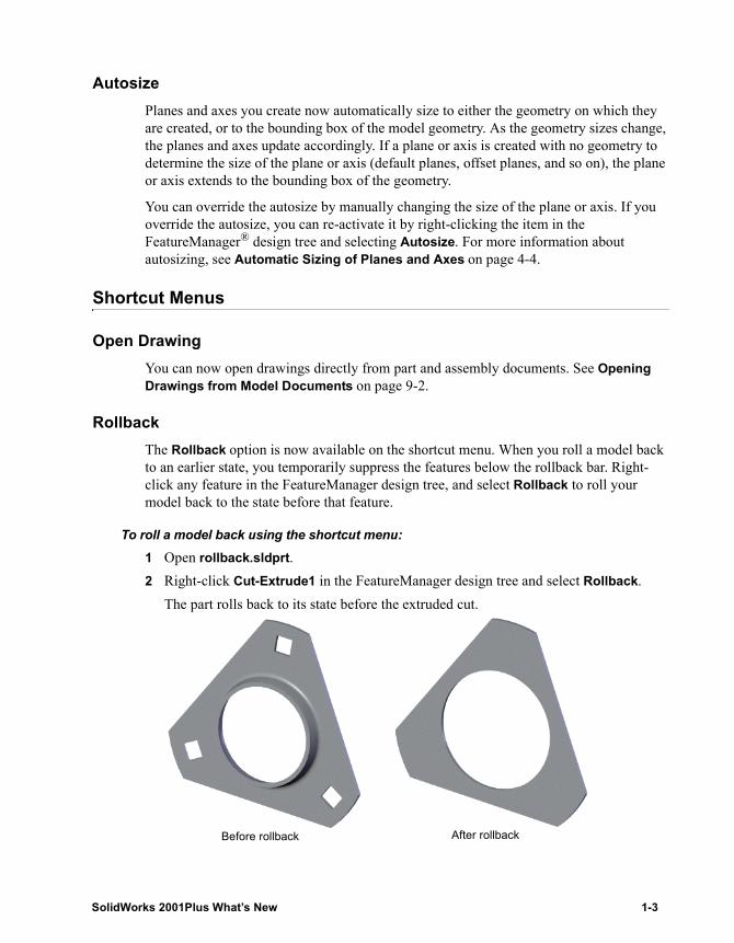
To roll a model back using the shortcut menu:1 Open rollback.sldprt.2 Right-click Cut-Extrude1 in the FeatureManager design tree and select Rollback.
The part rolls back to its state before the extruded cut.
Before rollback After rollback
SolidWorks 2001Plus What’s New 1-3
Chapter 1 SolidWorks Fundamentals
Select ChainSelect Chain has been added to the shortcut menu when selecting sketch entities. This command selects all sketch entities attached to the selected entity in both directions until a branch is encountered. For more information about select chain, see Select Chain on page 3-2.
Delete FaceIf you want to delete a face in a surface body, right-click the face and select Delete Face, or click on the Surfaces toolbar, or click Insert, Face, Delete. Previously, you had to select a face, then press Delete. For more information about the Delete Face functionality, see Deleting Faces in Surface Bodies on page 6-8.
Delete In the PropertyManager, you can right-click items in a list to delete them from the selection. For example, to delete a face selection from the Shell PropertyManager, right-click the face and click Delete.
Printing
When you set printing parameters, some options are saved as document options, while others are saved as system options. Document options include headers and footers, scale, orientation, paper size, and paper source. System options include line weights, margins, and background. Additional printing enhancements are described below.
Document Options
Header/Footer
There is a new method to set predefined or custom headers and footers for individual documents.
To create a header/footer:1 Click File, Print.
The Print dialog box appears.2 Under Document Options, click Header/Footer.
The Header/Footer dialog box appears.
NOTE: You must have a SolidWorks document open to set printing parameters.
1-4
3 Select a predefined header or footer from the Header and Footer lists.The predefined header or footer appears in the appropriate preview boxes.- or -Click Custom Header or Custom Footer to create a unique header or footer, select the items you want to appear on the page (Page Numbers, Number of Pages, Date, Time, or Filename), then click OK.
4 Click OK to close the Header/Footer dialog box.5 Click OK to close the Print dialog box and print the document.
System Options
Line Weights
There is a new method to set the line weights that work best with your printer or plotter.
To set line weights:1 Click File, Print.
The Print dialog box appears.2 Under System Options, click Line Weights.
The Line Weights dialog box appears.3 Set the line weights (Thin, Normal, and so on) to the desired values, then click OK.4 Click OK to close the Print dialog box and print the document.
Margins
There is a new method to set values for the top, bottom, left, and right margins for the printed document.
To set print margins:1 Click File, Print.
The Print dialog box appears.2 Under System Options, click Margins.
The Margins dialog box appears.3 Clear the Use printer’s margins check box.4 Set the Top, Bottom, Left, and Right margins to the desired values, then click OK.5 Click OK to close the Print dialog box and print the document.
SolidWorks 2001Plus What’s New 1-5
Chapter 1 SolidWorks Fundamentals
Drawings
Settings for individual drawing sheets
When you print a drawing for the first time, SolidWorks sets the default printer and paper size to the settings used in the last drawing printed. If you select Set each sheet individually, SolidWorks sets a default printer for each sheet according to its page size.
If you want to change the default settings, you can set specific printing options for each sheet in a drawing. For example, you can choose different settings such as the printer, scale, orientation, and so on, for each sheet.
To set print settings for drawing sheets:1 Click File, Print.
The Print dialog box appears.2 Under Document Options, click Page Setup.
The Page Setup dialog box appears.3 Under Individual Drawing Sheet Control, select Set each sheet individually, and do
the following:a) Select the sheet for which you want to apply the print settings from the Settings
for list.b) Choose print settings under Scale, Paper, Drawing Color, and Orientation.c) Repeat steps a and b for each sheet in the drawing.d) Click OK.
4 Click OK to close the Print dialog box and print the document.
1-6
Macros
If you click Edit Macro to edit macros that are password protected, the Macro Password Validation dialog box appears to verify your password.
Display
Transparency in AssembliesThere are new tools on the Assembly toolbar for setting transparency when you edit assembly components:
• Opaque . All components become opaque gray, except for the component you are editing, which becomes opaque pink.
• Force Transparency . All components become transparent except the one you are editing, which becomes opaque pink.
• Maintain Transparency . All components remain in their current state, except for the one you are editing, which becomes opaque pink.
For more information on transparency in assemblies, see Using Transparency in Assemblies on page 7-9.
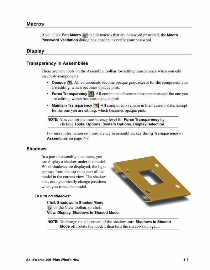
ShadowsIn a part or assembly document, you can display a shadow under the model. When shadows are displayed, the light appears from the top-most part of the model in the current view. The shadow does not dynamically change positions when you rotate the model.
To turn on shadows:Click Shadows In Shaded Mode
on the View toolbar, or click View, Display, Shadows In Shaded Mode.
NOTE: You can set the transparency level for Force Transparency by clicking Tools, Options, System Options, Display/Selection.
NOTE: To change the placement of the shadow, turn Shadows In Shaded Mode off, rotate the model, then turn the shadows on again.
SolidWorks 2001Plus What’s New 1-7
Chapter 1 SolidWorks Fundamentals
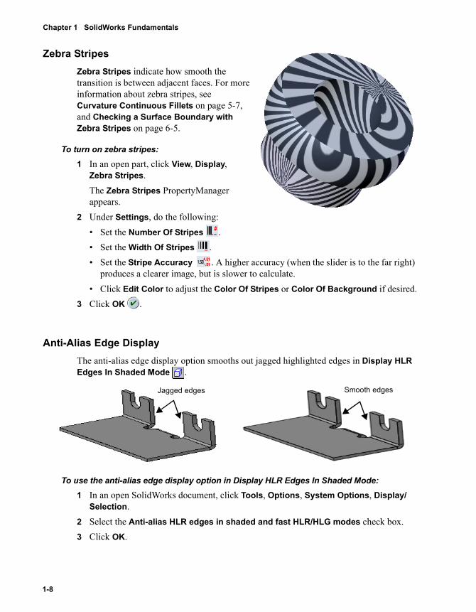
Zebra StripesZebra Stripes indicate how smooth the transition is between adjacent faces. For more information about zebra stripes, see Curvature Continuous Fillets on page 5-7, and Checking a Surface Boundary with Zebra Stripes on page 6-5.
To turn on zebra stripes:1 In an open part, click View, Display,
Zebra Stripes.The Zebra Stripes PropertyManager appears.
2 Under Settings, do the following:• Set the Number Of Stripes .• Set the Width Of Stripes .• Set the Stripe Accuracy . A higher accuracy (when the slider is to the far right)
produces a clearer image, but is slower to calculate. • Click Edit Color to adjust the Color Of Stripes or Color Of Background if desired.
3 Click OK .
Anti-Alias Edge DisplayThe anti-alias edge display option smooths out jagged highlighted edges in Display HLR Edges In Shaded Mode .
To use the anti-alias edge display option in Display HLR Edges In Shaded Mode:1 In an open SolidWorks document, click Tools, Options, System Options, Display/
Selection.2 Select the Anti-alias HLR edges in shaded and fast HLR/HLG modes check box.3 Click OK.
Jagged edges Smooth edges
1-8
Display HLR Edges in Shaded Mode ColorWhen your model is in Display HLR Edges In Shaded Mode , you can customize the color of the shaded edges. The default color is black.
To customize the color of shaded edges in Display HLR Edges in Shaded Mode:1 In an open SolidWorks document, click Tools, Options, System Options, Colors.2 Under System colors, click HLR Edges in Shaded Mode, then click Edit.3 Select a color from the color palette or define a custom color, then click OK.4 Select the Use specified color for HLR edges in shaded mode check box.5 Click OK.
Show/Hide Curves, Sketches, and AnnotationsYou can globally show all curves, sketches, or annotations in a SolidWorks document by selecting the feature in the View menu. To hide these features, deselect the feature in the View menu.
To hide all items in the View menu, (planes, axes, curves, and so on) click View, Hide All Types.
Using the Middle Mouse Wheel to ZoomIf you use a mouse with a wheel in the middle, you can zoom in to the position of the pointer instead of the center of the graphics area in a SolidWorks document. This is the default. If the pointer is outside of the graphics area, the center of the model zooms to view.
To turn this function off, click View, Modify, Zoom About Screen Center.
NOTE: If you select Hide All Types, you cannot show any hidden items until you deselect Hide All Types.
NOTE: While rolling the mouse wheel, you must keep the pointer on the area where you want to zoom.
SolidWorks 2001Plus What’s New 1-9
Chapter 1 SolidWorks Fundamentals
Remove Detail During Zoom/Pan/Rotate The Remove detail during zoom/pan/rotate option is used in SolidWorks assemblies for faster graphics display. This option removes small and interior components and faces from the graphics area to improve system performance.
To turn on Remove detail during zoom/pan/rotate:1 Click Tools, Options, System Options, Performance.2 Under Assemblies, select the Remove detail during zoom/pan/rotate check box.
3 Click OK.
DrawingsWhen you create a drawing, you now have the option to display the model in Shaded mode and to select Display HLR Edges In Shaded Mode . These views help you see the model easier in a drawing. For more information, see Displaying Drawing Views in Shaded Mode on page 9-2.
Library Features
Holes on non-planar surfaces that you create with the Hole Wizard can now be saved as library features.
Toolbars
There are two new toolbars in SolidWorks 2001Plus. These include:• Routing. See New Routing Toolbar on page 2-6.• 2D to 3D. See 2D to 3D Conversion on page 3-1.
NOTE: This option is automatically disabled when you move or rotate a component, during mate animation, and during drag and drop animation.
NOTE: When Remove detail during zoom/pan/rotate is turned on, the Optimize Zoom/Pan/Rotate option is available if the model is changed. Click View, Display or right-click in the graphics area and select Optimize Zoom/Pan/Rotate to recalculate which components and faces should be hidden.
1-10
PropertyManager
More functions now use the PropertyManager instead of dialog boxes, allowing your graphics to be displayed instead of hidden by dialog boxes. The following commands have been moved to or updated in the PropertyManager:
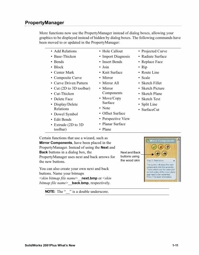
Certain functions that use a wizard, such as Mirror Components, have been placed in the PropertyManager. Instead of using the Next and Back buttons in a dialog box, the PropertyManager uses next and back arrows for the new buttons.
You can also create your own next and back buttons. Name your bitmaps <skin bitmap file name>__next.bmp or <skin bitmap file name>__back.bmp, respectively.
• Add Relations• Base-Thicken• Bends• Block• Center Mark• Composite Curve• Curve Driven Pattern• Cut (2D to 3D toolbar)• Cut-Thicken• Delete Face• Display/Delete
Relations• Dowel Symbol• Edit Bends• Extrude (2D to 3D
toolbar)
• Hole Callout• Import Diagnosis• Insert Bends• Join• Knit Surface• Mirror• Mirror All• Mirror
Components• Move/Copy
Surface• Note• Offset Surface• Perspective View• Planar Surface• Plane
• Projected Curve• Radiate Surface• Replace Face• Rip• Route Line• Scale• Sketch Fillet• Sketch Picture• Sketch Plane• Sketch Text• Split Line• SurfaceCut
NOTE: The “__” is a double underscore.
Next and Back buttons using the wood skin
SolidWorks 2001Plus What’s New 1-11
2 Sketching
There are new and enhanced 2D and 3D sketching functions in SolidWorks 2001Plus.
� User interface enhancements in sketching
� Override Dims on Drag with Move/Copy
� New Routing toolbar
� Pictures on sketch planes
� Sketch text on curves
� 3D sketching relations
� Enhancements to splines
SolidWorks 2001Plus What’s New 2-1
Chapter 2 Sketching
User Interface Enhancements in Sketching
The Confirmation Corner for Exit Sketch now allows you to exit the sketch without saving changes by clicking Cancel . This functionality is also available as a menu item, Edit, Exit Sketch without Saving Changes. A prompt asks if you are sure you want to discard the changes.
The following sketch menu items have been moved from the Tools, Sketch Tools menu to a new menu, Tools, Sketch Settings:
• Automatic Relations• Automatic Solve• Automatic Inferencing Lines• No Solve Move• Detach Segment on Drag• Override Dims on Drag (see Override Dims on Drag with Move/Copy on page
2-5)
The Align Grid item on the Tools, Sketch Tools menu is now Align, with submenu items Grid and Sketch. The following items have been added to the Tools, Sketch Tools menu. For further information, see Chapter 3, “2D to 3D Conversion.”
• Create new Sketch• Repair Sketch• 2D to 3D
The following sketch functions have been moved from dialog boxes to the PropertyManager and are discussed in detail in the next sections:
• Edit Sketch Plane• Sketch Fillet• Add Relations • Display/Delete Relations
Edit Sketch PlaneIn any part document, in the FeatureManager design tree, right-click a sketch and select Edit Sketch Plane. The Sketch Plane PropertyManager appears with the name of the plane in the Sketch Plane/Face box.
2-2
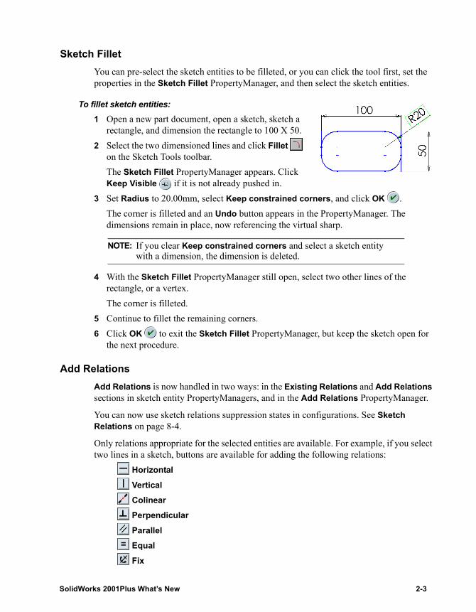
Sketch FilletYou can pre-select the sketch entities to be filleted, or you can click the tool first, set the properties in the Sketch Fillet PropertyManager, and then select the sketch entities.
To fillet sketch entities:1 Open a new part document, open a sketch, sketch a
rectangle, and dimension the rectangle to 100 X 50.2 Select the two dimensioned lines and click Fillet
on the Sketch Tools toolbar.The Sketch Fillet PropertyManager appears. Click Keep Visible if it is not already pushed in.
3 Set Radius to 20.00mm, select Keep constrained corners, and click OK .The corner is filleted and an Undo button appears in the PropertyManager. The dimensions remain in place, now referencing the virtual sharp.
4 With the Sketch Fillet PropertyManager still open, select two other lines of the rectangle, or a vertex.The corner is filleted.
5 Continue to fillet the remaining corners.6 Click OK to exit the Sketch Fillet PropertyManager, but keep the sketch open for
the next procedure.
Add RelationsAdd Relations is now handled in two ways: in the Existing Relations and Add Relations sections in sketch entity PropertyManagers, and in the Add Relations PropertyManager.
You can now use sketch relations suppression states in configurations. See Sketch Relations on page 8-4.
Only relations appropriate for the selected entities are available. For example, if you select two lines in a sketch, buttons are available for adding the following relations:
Horizontal
Vertical Colinear Perpendicular Parallel Equal Fix
NOTE: If you clear Keep constrained corners and select a sketch entity with a dimension, the dimension is deleted.
SolidWorks 2001Plus What’s New 2-3
Chapter 2 Sketching
Other combinations of sketch entities make additional relations available, including: Coincident Concentric Coradial Intersection Merge Midpoint Tangent
Relations are displayed in the Existing Relations box. Select the relation and a callout appears in the graphics area attached to the related sketch entity. The callout shows the name of the related entity and the type of relation.
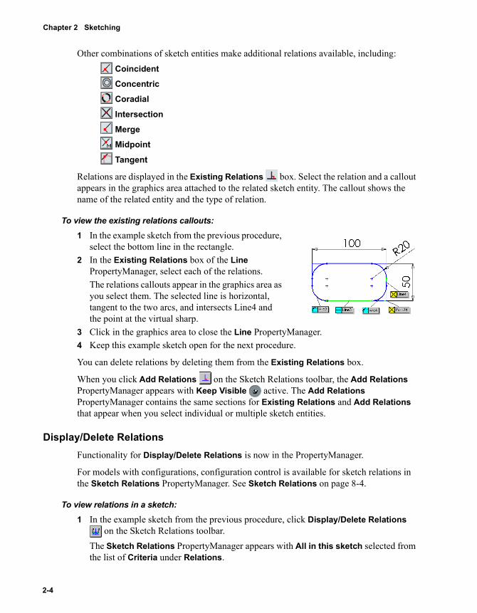
To view the existing relations callouts:1 In the example sketch from the previous procedure,
select the bottom line in the rectangle. 2 In the Existing Relations box of the Line
PropertyManager, select each of the relations. The relations callouts appear in the graphics area as you select them. The selected line is horizontal, tangent to the two arcs, and intersects Line4 and the point at the virtual sharp.
3 Click in the graphics area to close the Line PropertyManager.4 Keep this example sketch open for the next procedure.
You can delete relations by deleting them from the Existing Relations box.
When you click Add Relations on the Sketch Relations toolbar, the Add Relations PropertyManager appears with Keep Visible active. The Add Relations PropertyManager contains the same sections for Existing Relations and Add Relations that appear when you select individual or multiple sketch entities.
Display/Delete RelationsFunctionality for Display/Delete Relations is now in the PropertyManager.
For models with configurations, configuration control is available for sketch relations in the Sketch Relations PropertyManager. See Sketch Relations on page 8-4.
To view relations in a sketch:1 In the example sketch from the previous procedure, click Display/Delete Relations
on the Sketch Relations toolbar.The Sketch Relations PropertyManager appears with All in this sketch selected from the list of Criteria under Relations.
2-4
2 Select various relations from Relations and note the sketch entities listed under Entities and highlighted in green in the graphics area.Note the following information:• On the Information line under Relations, the status of the relation (Satisfied,
for example) is displayed. • Under Entities, the Status of the sketch entity (Under Defined, Fully Defined, and
so on) is displayed, along with the location of the entity (Current Sketch, for example).
3 In the Criteria list under Relations, choose Selected Entities from the list, and select the bottom line of the rectangle. The name of the line appears in the Selected Entities box. Note the relations listed.
4 Click OK to close the Sketch Relations PropertyManager.5 Keep this example sketch open for the next procedure.
Override Dims on Drag with Move/Copy
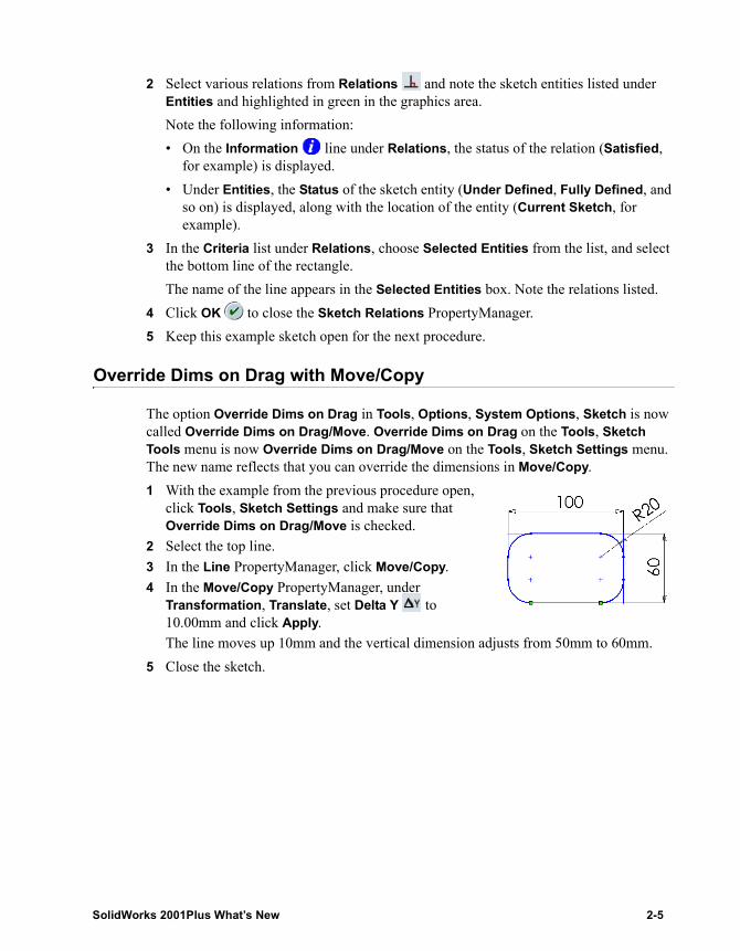
The option Override Dims on Drag in Tools, Options, System Options, Sketch is now called Override Dims on Drag/Move. Override Dims on Drag on the Tools, Sketch Tools menu is now Override Dims on Drag/Move on the Tools, Sketch Settings menu. The new name reflects that you can override the dimensions in Move/Copy.1 With the example from the previous procedure open,
click Tools, Sketch Settings and make sure that Override Dims on Drag/Move is checked.
2 Select the top line. 3 In the Line PropertyManager, click Move/Copy.4 In the Move/Copy PropertyManager, under
Transformation, Translate, set Delta Y to 10.00mm and click Apply.The line moves up 10mm and the vertical dimension adjusts from 50mm to 60mm.
5 Close the sketch.
SolidWorks 2001Plus What’s New 2-5
Chapter 2 Sketching
New Routing Toolbar
A new toolbar, Routing, contains two new tools for sketch lines: Route Line and Jog Line .
Route LineThe Route Line tool is used in explode line sketches. An Explode Line Sketch is a 3D sketch, and you can drag and jog the lines in the sketch as in any 3D sketch.
You insert an Explode Line Sketch into an assembly while the Configuration tab is selected, then you insert explode lines into the sketch with Route Line . Only one Explode Line Sketch can be inserted into a configuration.
For an example of creating explode lines in an assembly, see Assembly Explode Lines on page 7-6.
Jog LineYou can use the Jog Line tool to jog lines in 2D and 3D sketches in part, assembly, and drawing documents. The jog lines are automatically constrained to be perpendicular and parallel to the original line. You can drag and dimension jog lines.
The Jog Line tool stays active so you can insert multiple jogs.
In 3D sketches, you can press Tab to toggle between two planes.
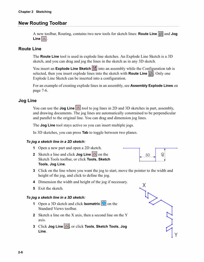
To jog a sketch line in a 2D sketch:1 Open a new part and open a 2D sketch.2 Sketch a line and click Jog Line on the
Sketch Tools toolbar, or click Tools, Sketch Tools, Jog Line.
3 Click on the line where you want the jog to start, move the pointer to the width and height of the jog, and click to define the jog.
4 Dimension the width and height of the jog if necessary.5 Exit the sketch.
To jog a sketch line in a 3D sketch:1 Open a 3D sketch and click Isometric on the
Standard Views toolbar.2 Sketch a line on the X axis, then a second line on the Y
axis.3 Click Jog Line , or click Tools, Sketch Tools, Jog
Line.
2-6
4 Click on the horizontal line where you want the jog to start, move the pointer to the width and height of the jog, and click to define the jog.
5 Click again on the same line and start the jog, but press Tab to change planes, move the pointer to the width and height of the jog, and click to define the jog.
6 Repeat steps 4 and 5 on the vertical line.7 Exit the sketch.
Pictures on Sketch Planes
You can insert pictures (.bmp, .gif, .jpg, .tif, or .wmf format) onto either side of sketch planes. Pictures can be used as an underlay for creating 2D sketches. The Sketch Picture PropertyManager controls a graphic’s position, size, angle, orientation, and whether to maintain its aspect ratio. A few items to note about pictures on sketch planes are:
• Sketch pictures are shown in the FeatureManager design tree, under their sketches• The shortcut menu contains Edit Sketch, Suppress, and Delete• If you sketch on top of the picture, there is no snap to picture or autotracing
capability. • If you hide the sketch, the image is also hidden. • The image is not linked. If you change the image, the sketch does not update.
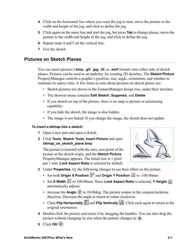
To insert a bitmap into a sketch:1 Open a new part and open a sketch.2 Click Tools, Sketch Tools, Insert Picture and open
bitmap_on_sketch_plane.bmp.The picture is inserted with the zero, zero point of the picture at the sketch origin, and the Sketch Picture PropertyManager appears. The initial size is 1 pixel per 1 mm. Lock Aspect Ratio is selected by default.
3 Under Properties, try the following changes to see their effect on the picture.• Set both Origin X Position and Origin Y Position to -100.00mm.• Set X Width to 100.00mm. Since Lock Aspect Ratio is selected, Y Height
automatically adjusts.• Increase the Angle to 10.00deg. The picture rotates in the counterclockwise
direction. Decrease the angle to return to rotate clockwise.• Click Flip Horizontally and Flip Vertically . Click each again to return to the
original orientation.4 Double-click the picture and resize it by dragging the handles. You can also drag the
picture without changing its size when the pointer changes to .5 Click OK .
SolidWorks 2001Plus What’s New 2-7
Chapter 2 Sketching
Sketch Text on Curves
You can sketch text on the face of a part and extrude or cut the text. Now this capability has been extended so that the text can be sketched on any set of continuous curves or edges, including circles or profiles made up of lines, arcs, curves, or splines. You can insert multiple texts in a sketch.
You can control the appearance of the text in the following ways:• Align the text left, right, or center, or justify it• Flip the text above or below the curve, and flip it horizontally• Scale the letters horizontally, scale the spaces, or scale letter size by percentage• Select a font face, style, size, and effects• Add bold or italic style• Rotate text
To edit text in a sketch, open the sketch, and double-click the text (the pointer changes to when it is over the text).
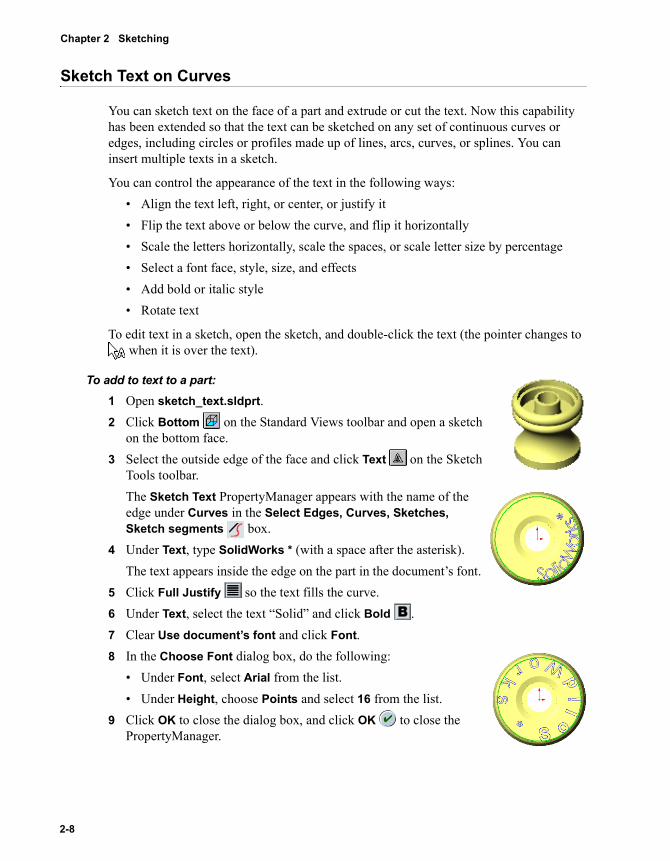
To add to text to a part:1 Open sketch_text.sldprt.2 Click Bottom on the Standard Views toolbar and open a sketch
on the bottom face.3 Select the outside edge of the face and click Text on the Sketch
Tools toolbar.The Sketch Text PropertyManager appears with the name of the edge under Curves in the Select Edges, Curves, Sketches, Sketch segments box.
4 Under Text, type SolidWorks * (with a space after the asterisk).The text appears inside the edge on the part in the document’s font.
5 Click Full Justify so the text fills the curve.6 Under Text, select the text “Solid” and click Bold .7 Clear Use document’s font and click Font.8 In the Choose Font dialog box, do the following:
• Under Font, select Arial from the list. • Under Height, choose Points and select 16 from the list.
9 Click OK to close the dialog box, and click OK to close the PropertyManager.
2-8
To extrude the text:1 With the sketch still open, click Extruded Cut on the
Features toolbar.2 In the Cut-Extrude PropertyManager, under Direction 1, leave
End Condition as Blind and set Depth to 1.00mm.3 Click OK .
To edit the text or its properties, edit the sketch, move the pointer over the text (the pointer changes to ), then right-click and select Properties. The Sketch Text PropertyManager reappears.
Inspect Curvature
Inspect Curvature has been available on the shortcut menu for splines. Now the functionality has been expanded as follows:
• Most sketch entities support Inspect Curvature.• The curvature combs remain visible when a sketch is closed.• You can turn off the display with a shortcut menu item Remove Curvature
Information.
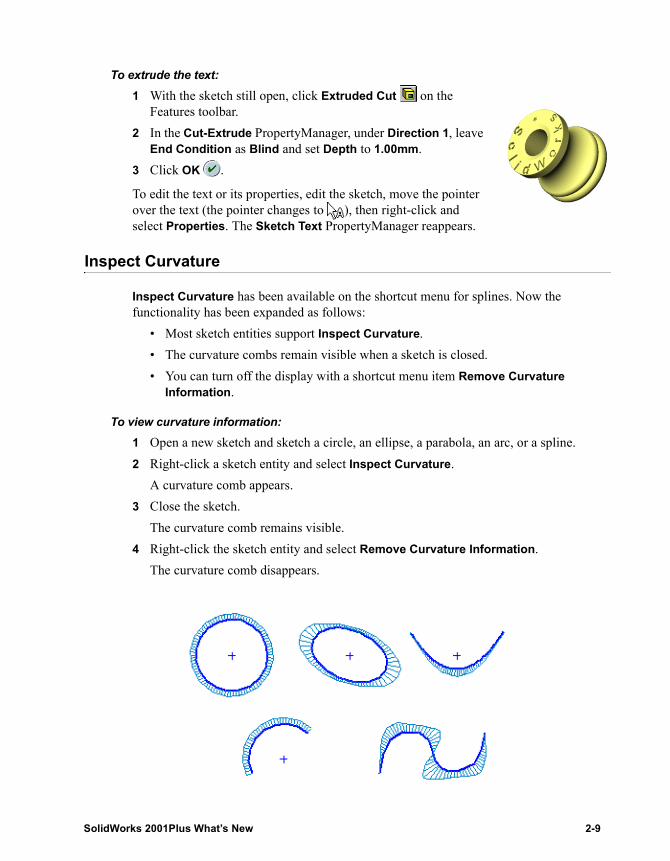
To view curvature information:1 Open a new sketch and sketch a circle, an ellipse, a parabola, an arc, or a spline.2 Right-click a sketch entity and select Inspect Curvature.
A curvature comb appears.3 Close the sketch.
The curvature comb remains visible.4 Right-click the sketch entity and select Remove Curvature Information.
The curvature comb disappears.
SolidWorks 2001Plus What’s New 2-9
Chapter 2 Sketching
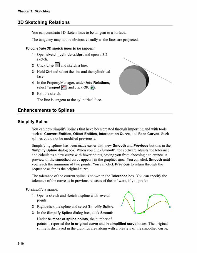
3D Sketching Relations
You can constrain 3D sketch lines to be tangent to a surface.
The tangency may not be obvious visually as the lines are projected.
To constrain 3D sketch lines to be tangent:1 Open sketch_cylinder.sldprt and open a 3D
sketch.2 Click Line and sketch a line.3 Hold Ctrl and select the line and the cylindrical
face.4 In the PropertyManager, under Add Relations,
select Tangent , and click OK .5 Exit the sketch.
The line is tangent to the cylindrical face.
Enhancements to Splines
Simplify SplineYou can now simplify splines that have been created through importing and with tools such as Convert Entities, Offset Entities, Intersection Curve, and Face Curves. Such splines could not be modified previously.
Simplifying splines has been made easier with new Smooth and Previous buttons in the Simplify Spline dialog box. When you click Smooth, the software adjusts the tolerance and calculates a new curve with fewer points, saving you from choosing a tolerance. A preview of the smoothed curve appears in the graphics area. You can click Smooth until you reach the minimum of two points. You can click Previous to return through the sequence as far as the original curve.
The tolerance of the current spline is shown in the Tolerance box. You can specify the tolerance of the curve as in previous releases of the software, if you prefer.
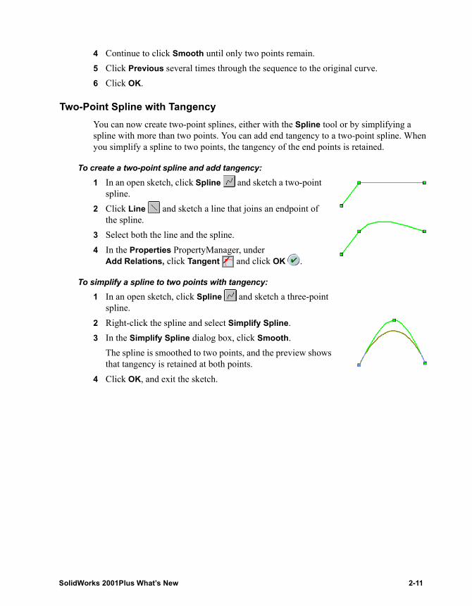
To simplify a spline:1 Open a sketch and sketch a spline with several
points.2 Right-click the spline and select Simplify Spline.3 In the Simplify Spline dialog box, click Smooth.
Under Number of spline points, the number of points is reported the In original curve and In simplified curve boxes. The original spline is displayed in the graphics area along with a preview of the smoothed curve.
2-10
4 Continue to click Smooth until only two points remain.5 Click Previous several times through the sequence to the original curve.6 Click OK.
Two-Point Spline with TangencyYou can now create two-point splines, either with the Spline tool or by simplifying a spline with more than two points. You can add end tangency to a two-point spline. When you simplify a spline to two points, the tangency of the end points is retained.
To create a two-point spline and add tangency:1 In an open sketch, click Spline and sketch a two-point
spline.2 Click Line and sketch a line that joins an endpoint of
the spline.3 Select both the line and the spline.4 In the Properties PropertyManager, under
Add Relations, click Tangent and click OK .
To simplify a spline to two points with tangency:1 In an open sketch, click Spline and sketch a three-point
spline.2 Right-click the spline and select Simplify Spline.3 In the Simplify Spline dialog box, click Smooth.
The spline is smoothed to two points, and the preview shows that tangency is retained at both points.
4 Click OK, and exit the sketch.
SolidWorks 2001Plus What’s New 2-11
3 2D to 3D Conversion
A new set of tools for 2D to 3D conversion is introduced in SolidWorks 2001Plus.
� Introduction
� Sketch tools
� Converting a 2D drawing to a 3D part
� Extracting sketches
� Aligning sketches
� Extruding a base feature
� Cutting features
SolidWorks 2001Plus What’s New 3-1
Chapter 3 2D to 3D Conversion
Introduction
You can now convert imported 2D drawings into 3D models using new conversion tools on the 2D to 3D toolbar and the Sketch Tools menu. Converting a drawing to a part by this method in most cases is faster than constructing the same part by creating a sketch.
The 2D sketch can be an imported drawing or it can be a sketch constructed in SolidWorks. In either case, you are working from a single sketch in a part document.
When importing a drawing into a part document, open the .dwg or .dxf file in SolidWorks. In the DXF/DWG Import dialog box, select Import to a new part, and then select Import to a 2D sketch. The drawing appears as Sketch1.
When you import DXF/DWG drawings for 2D to 3D conversion, it is recommended that you eliminate crosshatching. See Crosshatches on page 10-5.
Sketch Tools
The tools described in this section are used in the 2D to 3D conversion process, and they can also be used for sketching in general.
Select ChainSelect Chain has been added to the shortcut menu when selecting sketch entities. This command selects all sketch entities attached to the selected entity in both directions until a branch is encountered. Select Chain is especially useful for selecting geometry for conversion from an imported drawing, but it can also be used with sketches created in SolidWorks.
To select a chain of sketch entities:1 Open a new part and open a sketch.2 Click Rectangle and sketch a rectangle, then sketch
another rectangle inside the first.3 Exit the sketch.4 Right-click one side of one rectangle and choose Select Chain.
All sides of the rectangle are selected.5 Hold Ctrl, right-click one side of the other rectangle, and choose Select Chain.
All sides of both rectangles are selected.6 Keep the part open for the next procedure.
NOTE: Even though the sketch used for conversion can be an imported drawing, it must be imported into a sketch in a part document. You can copy and paste the sketch from a drawing document, or you can import the drawing directly into a 2D part sketch.
3-2
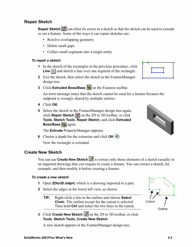
Repair SketchRepair Sketch can often fix errors in a sketch so that the sketch can be used to extrude or cut a feature. Some of the ways it can repair sketches are:
• Resolve overlapping geometry• Delete small gaps• Collect small segments into a single entity
To repair a sketch:1 In the sketch of the rectangles in the previous procedure, click
Line and sketch a line over one segment of the rectangle.2 Exit the sketch, then select the sketch in the FeatureManager
design tree.3 Click Extruded Boss/Base on the Features toolbar.
An error message states that the sketch cannot be used for a feature because the endpoint is wrongly shared by multiple entities.
4 Click OK.5 Select the sketch in the FeatureManager design tree again,
click Repair Sketch on the 2D to 3D toolbar, or click Tools, Sketch Tools, Repair Sketch, and click Extruded Boss/Base again.The Extrude PropertyManager appears.
6 Choose a depth for the extrusion and click OK .Now the rectangle is extruded.
Create New SketchYou can use Create New Sketch to extract only those elements of a sketch (usually in an imported drawing) that you require to create a feature. You can extract a sketch, for example, and then modify it before creating a feature.
To create a new sketch:1 Open 2Dto3D.sldprt, which is a drawing imported to a part.2 Select the edges in the lower left view, as shown.
3 Click Create New Sketch on the 2D to 3D toolbar, or click Tools, Sketch Tools, Create New Sketch.A new sketch appears in the FeatureManager design tree.
TIP: Right-click a line in the outline and choose Select Chain. The outline except for the cutout is selected. Then hold Ctrl and select the two lines in the cutout.
Cutout
Outline
SolidWorks 2001Plus What’s New 3-3
Chapter 3 2D to 3D Conversion
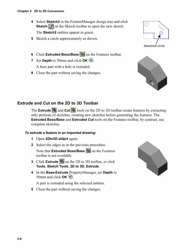
4 Select Sketch2 in the FeatureManager design tree and click Sketch on the Sketch toolbar to open the new sketch.The Sketch2 entities appear in green.
5 Sketch a circle approximately as shown.
6 Click Extruded Boss/Base on the Features toolbar.7 Set Depth to 50mm and click OK .
A base part with a hole is extruded.8 Close the part without saving the changes.
Extrude and Cut on the 2D to 3D ToolbarThe Extrude and Cut tools on the 2D to 3D toolbar create features by extracting only portions of sketches, creating new sketches before generating the features. The Extruded Boss/Base and Extruded Cut tools on the Features toolbar, by contrast, use complete sketches.
To extrude a feature in an imported drawing:1 Open 2Dto3D.sldprt again.2 Select the edges as in the previous procedure.
Note that Extruded Boss/Base on the Features toolbar is not available.
3 Click Extrude on the 2D to 3D toolbar, or click Tools, Sketch Tools, 2D to 3D, Extrude.
4 In the Base-Extrude PropertyManager, set Depth to 50mm and click OK .A part is extruded using the selected entities.
5 Close the part without saving the changes.
Sketched circle
3-4
Converting a 2D Drawing to a 3D Part
The 2D to 3D tools facilitate converting a single sketch into a set of separate sketches, each positioned and oriented as required to create a 3D model. The tools fold up the 2D sketch as if it were a piece of paper.
When you import a drawing for conversion, you specify which portions of the drawing are the sketches for the front view, right view, and so on. You can also create auxiliary sketches that are not parallel to the principal view planes. Hidden lines, which are dashed lines in an imported drawing, are construction lines.
You use the 2D to 3D tools to align sketches with each other, with edges and vertices of a part, or with the origin. You can align sketches before you use them to create a part, or you can align sketches during the part construction process.
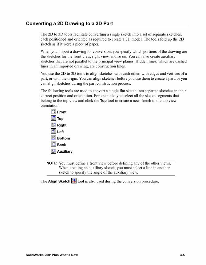
The following tools are used to convert a single flat sketch into separate sketches in their correct position and orientation. For example, you select all the sketch segments that belong to the top view and click the Top tool to create a new sketch in the top view orientation.
Front Top Right Left Bottom Back Auxiliary
The Align Sketch tool is also used during the conversion procedure.
NOTE: You must define a front view before defining any of the other views. When creating an auxiliary sketch, you must select a line in another sketch to specify the angle of the auxiliary view.
SolidWorks 2001Plus What’s New 3-5
Chapter 3 2D to 3D Conversion
Extracting Sketches
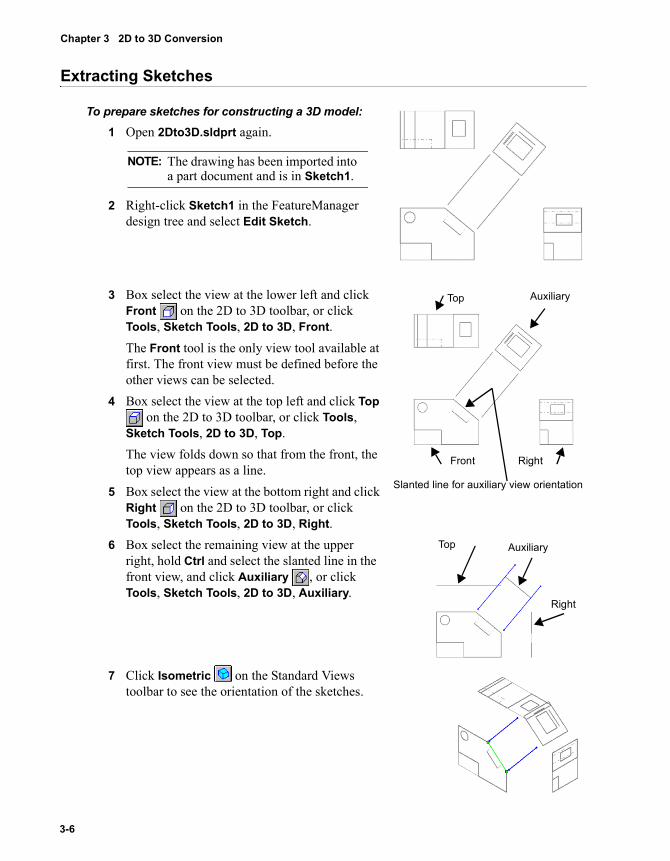
To prepare sketches for constructing a 3D model:1 Open 2Dto3D.sldprt again.
2 Right-click Sketch1 in the FeatureManager design tree and select Edit Sketch.
3 Box select the view at the lower left and click Front on the 2D to 3D toolbar, or click Tools, Sketch Tools, 2D to 3D, Front.The Front tool is the only view tool available at first. The front view must be defined before the other views can be selected.
4 Box select the view at the top left and click Top on the 2D to 3D toolbar, or click Tools,
Sketch Tools, 2D to 3D, Top.The view folds down so that from the front, the top view appears as a line.
5 Box select the view at the bottom right and click Right on the 2D to 3D toolbar, or click Tools, Sketch Tools, 2D to 3D, Right.
6 Box select the remaining view at the upper right, hold Ctrl and select the slanted line in the front view, and click Auxiliary , or click Tools, Sketch Tools, 2D to 3D, Auxiliary.
7 Click Isometric on the Standard Views toolbar to see the orientation of the sketches.
NOTE: The drawing has been imported into a part document and is in Sketch1.
Front Right
Top Auxiliary
Slanted line for auxiliary view orientation
Top Auxiliary
Right
3-6
Aligning Sketches
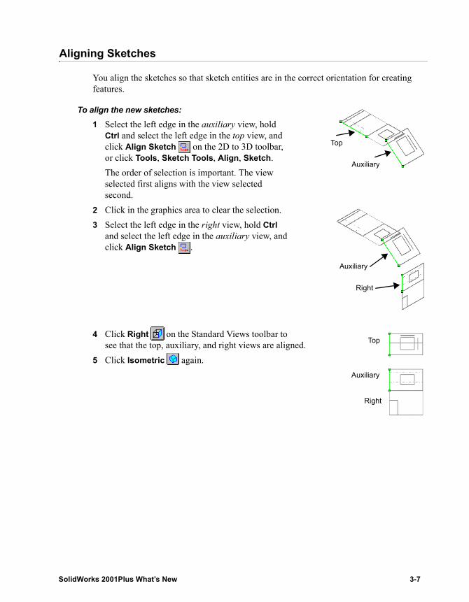
You align the sketches so that sketch entities are in the correct orientation for creating features.
To align the new sketches:1 Select the left edge in the auxiliary view, hold
Ctrl and select the left edge in the top view, and click Align Sketch on the 2D to 3D toolbar, or click Tools, Sketch Tools, Align, Sketch.The order of selection is important. The view selected first aligns with the view selected second.
2 Click in the graphics area to clear the selection.3 Select the left edge in the right view, hold Ctrl
and select the left edge in the auxiliary view, and click Align Sketch .
4 Click Right on the Standard Views toolbar to see that the top, auxiliary, and right views are aligned.
5 Click Isometric again.
Top
Auxiliary
Auxiliary
Right
Top
Auxiliary
Right
SolidWorks 2001Plus What’s New 3-7
Chapter 3 2D to 3D Conversion
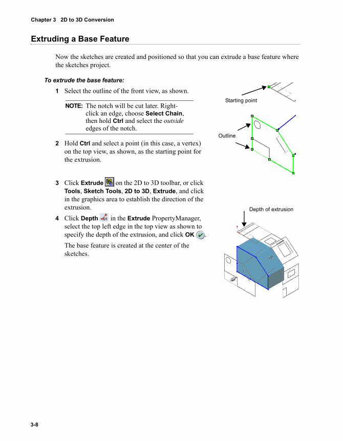
Extruding a Base Feature
Now the sketches are created and positioned so that you can extrude a base feature where the sketches project.
To extrude the base feature:1 Select the outline of the front view, as shown.
2 Hold Ctrl and select a point (in this case, a vertex) on the top view, as shown, as the starting point for the extrusion.
3 Click Extrude on the 2D to 3D toolbar, or click Tools, Sketch Tools, 2D to 3D, Extrude, and click in the graphics area to establish the direction of the extrusion.
4 Click Depth in the Extrude PropertyManager, select the top left edge in the top view as shown to specify the depth of the extrusion, and click OK .The base feature is created at the center of the sketches.
NOTE: The notch will be cut later. Right-click an edge, choose Select Chain, then hold Ctrl and select the outside edges of the notch.
Outline
Starting point
Depth of extrusion
3-8
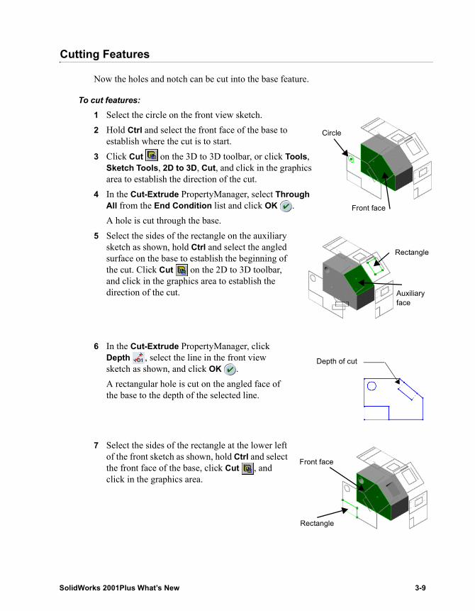
Cutting Features
Now the holes and notch can be cut into the base feature.
To cut features:1 Select the circle on the front view sketch.2 Hold Ctrl and select the front face of the base to
establish where the cut is to start.3 Click Cut on the 3D to 3D toolbar, or click Tools,
Sketch Tools, 2D to 3D, Cut, and click in the graphics area to establish the direction of the cut.
4 In the Cut-Extrude PropertyManager, select Through All from the End Condition list and click OK .A hole is cut through the base.
5 Select the sides of the rectangle on the auxiliary sketch as shown, hold Ctrl and select the angled surface on the base to establish the beginning of the cut. Click Cut on the 2D to 3D toolbar, and click in the graphics area to establish the direction of the cut.
6 In the Cut-Extrude PropertyManager, click Depth , select the line in the front view sketch as shown, and click OK .A rectangular hole is cut on the angled face of the base to the depth of the selected line.
7 Select the sides of the rectangle at the lower left of the front sketch as shown, hold Ctrl and select the front face of the base, click Cut , and click in the graphics area.
Circle
Front face
Rectangle
Auxiliary face
Depth of cut
Rectangle
Front face
SolidWorks 2001Plus What’s New 3-9
Chapter 3 2D to 3D Conversion
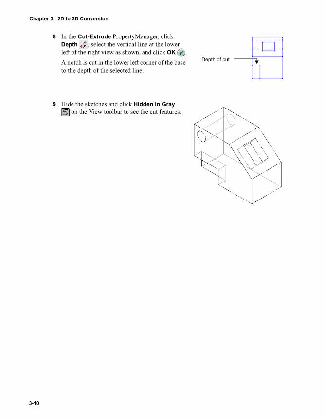
8 In the Cut-Extrude PropertyManager, click Depth , select the vertical line at the lower left of the right view as shown, and click OK .A notch is cut in the lower left corner of the base to the depth of the selected line.
9 Hide the sketches and click Hidden in Gray on the View toolbar to see the cut features.
Depth of cut
3-10
4 Reference Geometry
This chapter describes the enhancements to Reference Geometry items, including:
� Planes
� Projected curves
� Composite curves
� Split lines
SolidWorks 2001Plus What’s New 4-1
Chapter 4 Reference Geometry
Planes
Plane CreationAll plane creation dialog boxes have moved to the Plane PropertyManager. All previous dialog box functionality is retained in the PropertyManager.
New functionality includes the following:• The 3 Points and Line&Point plane options are combined into one
Through Lines/Points option in the PropertyManager.• You can create multiple offset planes by setting the
Number of Planes to Create . Each plane is created separately using the offset distance from the selected plane.
• When you have selected enough entities to create a plane, the OK pointer appears. Right-click to create the plane.
• If you select items before creating the plane, SolidWorks attempts to select the appropriate type of plane. You can always select a different type of plane.
• Some selection capabilities are now also included in the shortcut menu you access by right-clicking in the graphics area.
• You can keep the Plane PropertyManager open by clicking Keep Visible , which is useful when creating multiple planes of various types.
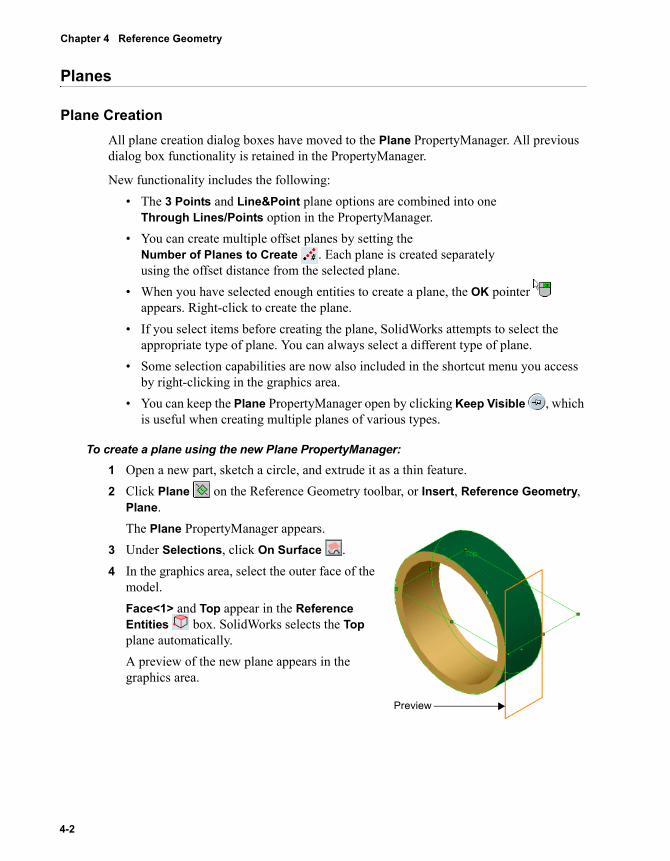
To create a plane using the new Plane PropertyManager:1 Open a new part, sketch a circle, and extrude it as a thin feature.2 Click Plane on the Reference Geometry toolbar, or Insert, Reference Geometry,
Plane.The Plane PropertyManager appears.
3 Under Selections, click On Surface .4 In the graphics area, select the outer face of the
model.Face<1> and Top appear in the Reference Entities box. SolidWorks selects the Top plane automatically.A preview of the new plane appears in the graphics area.
Preview
4-2
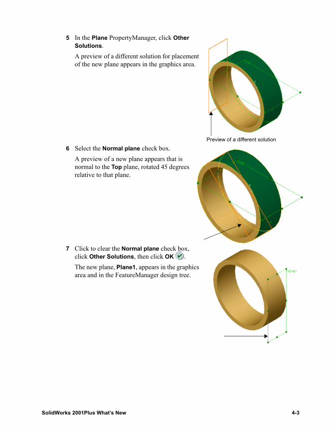
5 In the Plane PropertyManager, click Other Solutions.A preview of a different solution for placement of the new plane appears in the graphics area.
6 Select the Normal plane check box.A preview of a new plane appears that is normal to the Top plane, rotated 45 degrees relative to that plane.
7 Click to clear the Normal plane check box, click Other Solutions, then click OK .The new plane, Plane1, appears in the graphics area and in the FeatureManager design tree.
Preview of a different solution
SolidWorks 2001Plus What’s New 4-3
Chapter 4 Reference Geometry
Automatic Sizing of Planes and AxesPlanes and axes you create now automatically size to either the geometry on which they are created, or to the bounding box of the model geometry. As the geometry changes size, the planes and axes update accordingly. You can override the automatic sizing by manually changing the plane or axis size, which disables future autosizing for that entity. You can re-enable autosizing by using the new Autosize shortcut menu item.
Previously, plane and axes displayed at a default size that was often too large or too small for the geometry on which they were created.
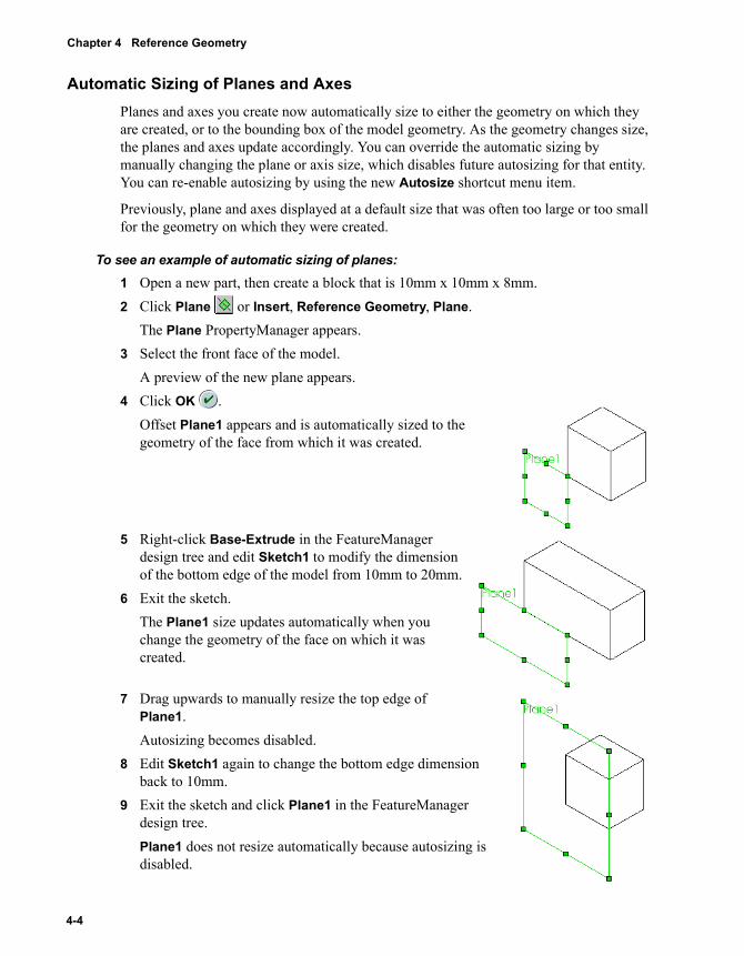
To see an example of automatic sizing of planes:1 Open a new part, then create a block that is 10mm x 10mm x 8mm.2 Click Plane or Insert, Reference Geometry, Plane.
The Plane PropertyManager appears.3 Select the front face of the model.
A preview of the new plane appears.4 Click OK .
Offset Plane1 appears and is automatically sized to the geometry of the face from which it was created.
5 Right-click Base-Extrude in the FeatureManager design tree and edit Sketch1 to modify the dimension of the bottom edge of the model from 10mm to 20mm.
6 Exit the sketch.The Plane1 size updates automatically when you change the geometry of the face on which it was created.
7 Drag upwards to manually resize the top edge of Plane1.Autosizing becomes disabled.
8 Edit Sketch1 again to change the bottom edge dimension back to 10mm.
9 Exit the sketch and click Plane1 in the FeatureManager design tree.Plane1 does not resize automatically because autosizing is disabled.
4-4
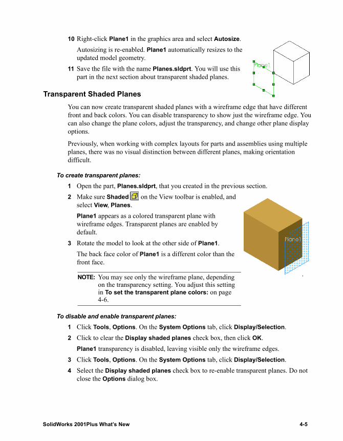
10 Right-click Plane1 in the graphics area and select Autosize.Autosizing is re-enabled. Plane1 automatically resizes to the updated model geometry.
11 Save the file with the name Planes.sldprt. You will use this part in the next section about transparent shaded planes.
Transparent Shaded PlanesYou can now create transparent shaded planes with a wireframe edge that have different front and back colors. You can disable transparency to show just the wireframe edge. You can also change the plane colors, adjust the transparency, and change other plane display options.
Previously, when working with complex layouts for parts and assemblies using multiple planes, there was no visual distinction between different planes, making orientation difficult.
To create transparent planes:1 Open the part, Planes.sldprt, that you created in the previous section.2 Make sure Shaded on the View toolbar is enabled, and
select View, Planes.Plane1 appears as a colored transparent plane with wireframe edges. Transparent planes are enabled by default.
3 Rotate the model to look at the other side of Plane1.The back face color of Plane1 is a different color than the front face.
To disable and enable transparent planes:1 Click Tools, Options. On the System Options tab, click Display/Selection.2 Click to clear the Display shaded planes check box, then click OK.
Plane1 transparency is disabled, leaving visible only the wireframe edges.3 Click Tools, Options. On the System Options tab, click Display/Selection.4 Select the Display shaded planes check box to re-enable transparent planes. Do not
close the Options dialog box.
NOTE: You may see only the wireframe plane, depending on the transparency setting. You adjust this setting in To set the transparent plane colors: on page 4-6.
SolidWorks 2001Plus What’s New 4-5
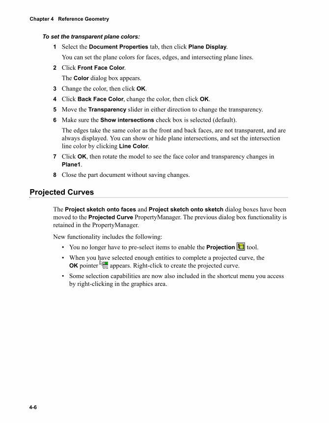
Chapter 4 Reference Geometry
To set the transparent plane colors:1 Select the Document Properties tab, then click Plane Display.
You can set the plane colors for faces, edges, and intersecting plane lines.2 Click Front Face Color.
The Color dialog box appears.3 Change the color, then click OK.4 Click Back Face Color, change the color, then click OK.5 Move the Transparency slider in either direction to change the transparency.6 Make sure the Show intersections check box is selected (default).
The edges take the same color as the front and back faces, are not transparent, and are always displayed. You can show or hide plane intersections, and set the intersection line color by clicking Line Color.
7 Click OK, then rotate the model to see the face color and transparency changes in Plane1.
8 Close the part document without saving changes.
Projected Curves
The Project sketch onto faces and Project sketch onto sketch dialog boxes have been moved to the Projected Curve PropertyManager. The previous dialog box functionality is retained in the PropertyManager.
New functionality includes the following:• You no longer have to pre-select items to enable the Projection tool. • When you have selected enough entities to complete a projected curve, the
OK pointer appears. Right-click to create the projected curve. • Some selection capabilities are now also included in the shortcut menu you access
by right-clicking in the graphics area.
4-6
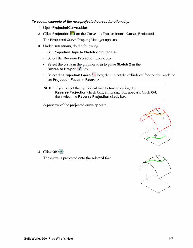
To see an example of the new projected curves functionality:1 Open ProjectedCurve.sldprt.2 Click Projection on the Curves toolbar, or Insert, Curve, Projected.
The Projected Curve PropertyManager appears.3 Under Selections, do the following:
• Set Projection Type to Sketch onto Face(s)• Select the Reverse Projection check box• Select the curve in the graphics area to place Sketch 2 in the
Sketch to Project box• Select the Projection Faces box, then select the cylindrical face on the model to
set Projection Faces to Face<1>
A preview of the projected curve appears.
4 Click OK .The curve is projected onto the selected face.
NOTE: If you select the cylindrical face before selecting the Reverse Projection check box, a message box appears. Click OK, then select the Reverse Projection check box.
SolidWorks 2001Plus What’s New 4-7
Chapter 4 Reference Geometry
Composite Curves
The Composite Curve dialog box has been moved to the Composite Curve PropertyManager. The previous dialog box functionality is retained in the PropertyManager.
New functionality includes the following:• When you have selected enough entities to complete a composite curve, the
OK pointer appears. If you have selected all the desired entities, right-click to create the composite curve.
• Some selection capabilities are now also included in the shortcut menu you access by right-clicking in the graphics area.
Split Lines
The Split Lines dialog box has been moved to the Split Lines PropertyManager. The previous dialog box functionality is retained in the PropertyManager.
New functionality includes the following:• When you have selected enough entities to create a split line, the OK pointer
appears. Right-click to create the split line. • Some selection capabilities are now also included in the shortcut menu you access
by right-clicking in the graphics area.
4-8
5 Features
Features are the individual shapes that, when combined, make up the part. The 3D part is the basic building block of the SolidWorks mechanical design software. Changes include the following:
� Migrations to the PropertyManager
� Shaded previews for lofts and sweeps
� Faces to pattern for mirror functions
� Pattern along a planar curve
� Curvature continuous fillets
� Control points for variable radius fillets
� Fillet by feature
� Loft add section
� Loft side tangency
� Translate surface option with offset from surface extrude
� Hole Wizard on non-planar faces
� Delete faces on a solid
� Draft analysis tool
SolidWorks 2001Plus What’s New 5-1
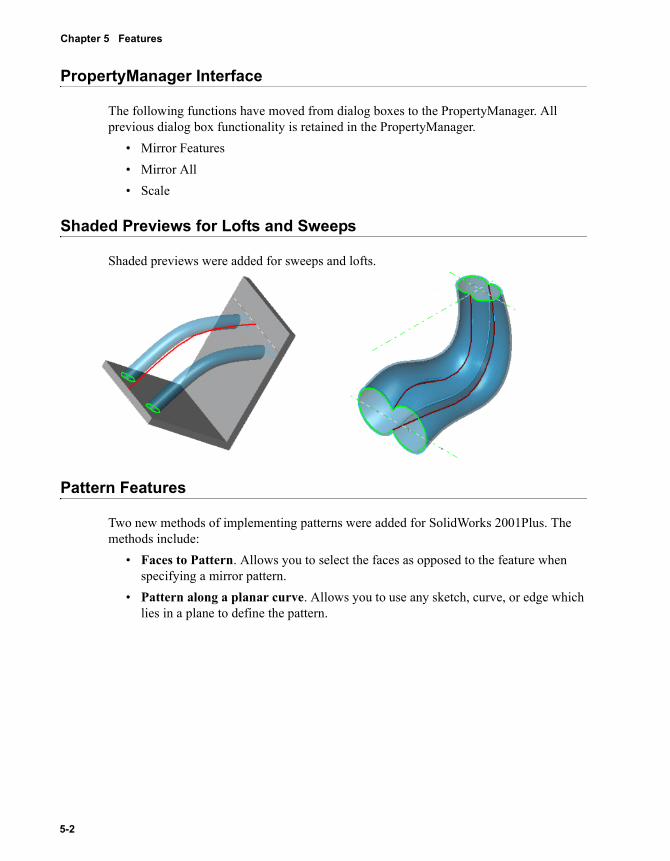
Chapter 5 Features
PropertyManager Interface
The following functions have moved from dialog boxes to the PropertyManager. All previous dialog box functionality is retained in the PropertyManager.
• Mirror Features• Mirror All• Scale
Shaded Previews for Lofts and Sweeps
Shaded previews were added for sweeps and lofts.
Pattern Features
Two new methods of implementing patterns were added for SolidWorks 2001Plus. The methods include:
• Faces to Pattern. Allows you to select the faces as opposed to the feature when specifying a mirror pattern.
• Pattern along a planar curve. Allows you to use any sketch, curve, or edge which lies in a plane to define the pattern.
5-2
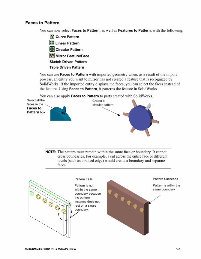
Faces to PatternYou can now select Faces to Pattern, as well as Features to Pattern, with the following:
Curve Pattern
Linear Pattern Circular Pattern Mirror Feature/Face
Sketch Driven PatternTable Driven Pattern
You can use Faces to Pattern with imported geometry when, as a result of the import process, an entity you want to mirror has not created a feature that is recognized by SolidWorks. If the imported entity displays the faces, you can select the faces instead of the feature. Using Faces to Pattern, it patterns the feature in SolidWorks.
You can also apply Faces to Pattern to parts created with SolidWorks.
NOTE: The pattern must remain within the same face or boundary. It cannot cross boundaries. For example, a cut across the entire face or different levels (such as a raised edge) would create a boundary and separate faces.
Select all the faces in the Faces to Pattern box
Create a circular pattern.
Pattern Fails
Pattern is not within the same boundary because the pattern instance does not rest on a single boundary.
Pattern Succeeds
Pattern is within the same boundary
SolidWorks 2001Plus What’s New 5-3
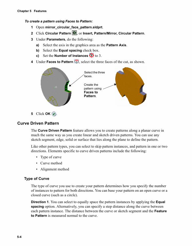
Chapter 5 Features
To create a pattern using Faces to Pattern:1 Open mirror_circular_face_pattern.sldprt.2 Click Circular Pattern , or Insert, Pattern/Mirror, Circular Pattern.3 Under Parameters, do the following:
a) Select the axis in the graphics area as the Pattern Axis.b) Select the Equal spacing check box.c) Set the Number of Instances to 3.
4 Under Faces to Pattern , select the three faces of the cut, as shown.
5 Click OK .
Curve Driven PatternThe Curve Driven Pattern feature allows you to create patterns along a planar curve in much the same way as you create linear and sketch driven patterns. You can use any sketch segment, edge, solid or surface that lies along the plane to define the pattern.
Like other pattern types, you can select to skip pattern instances, and pattern in one or two directions. Elements specific to curve driven patterns include the following:
• Type of curve• Curve method• Alignment method
Type of Curve
The type of curve you use to create your pattern determines how you specify the number of instances to pattern for both directions. You can base your pattern on an open curve or a closed curve (such as a circle).
Direction 1. You can select to equally space the pattern instances by applying the Equal spacing option. Alternatively, you can specify a step distance along the curve between each pattern instance. The distance between the curve or sketch segment and the Feature to Pattern is measured normal to the curve.
Select the three faces.
Create the pattern using Faces to Pattern.
5-4
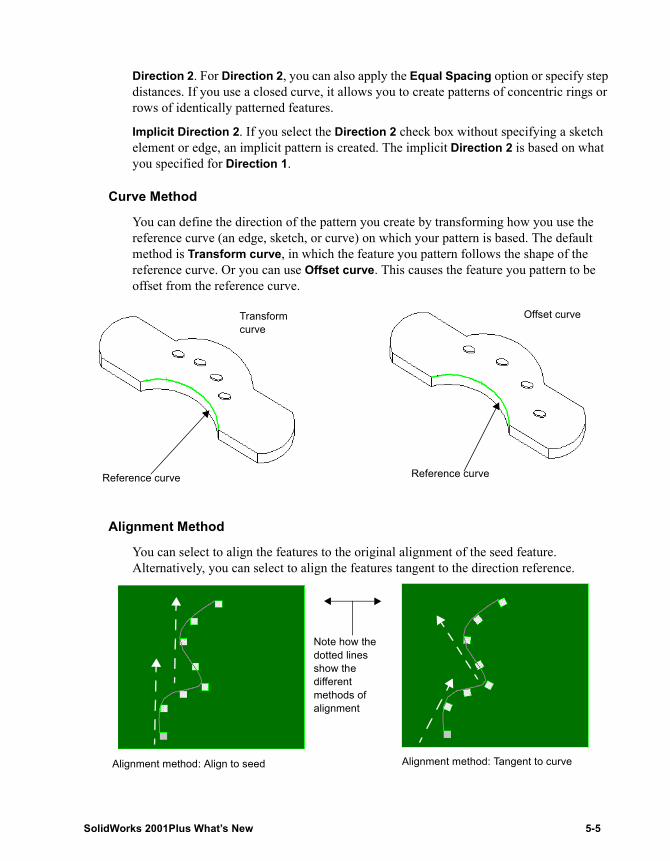
Direction 2. For Direction 2, you can also apply the Equal Spacing option or specify step distances. If you use a closed curve, it allows you to create patterns of concentric rings or rows of identically patterned features.
Implicit Direction 2. If you select the Direction 2 check box without specifying a sketch element or edge, an implicit pattern is created. The implicit Direction 2 is based on what you specified for Direction 1.
Curve Method
You can define the direction of the pattern you create by transforming how you use the reference curve (an edge, sketch, or curve) on which your pattern is based. The default method is Transform curve, in which the feature you pattern follows the shape of the reference curve. Or you can use Offset curve. This causes the feature you pattern to be offset from the reference curve.
Alignment Method
You can select to align the features to the original alignment of the seed feature. Alternatively, you can select to align the features tangent to the direction reference.
Transform curve
Offset curve
Reference curveReference curve
Alignment method: Align to seed Alignment method: Tangent to curve
Note how the dotted lines show the different methods of alignment
SolidWorks 2001Plus What’s New 5-5
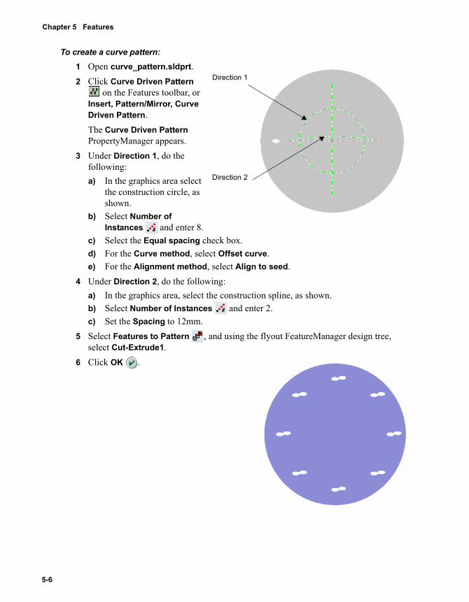
Chapter 5 Features
To create a curve pattern:1 Open curve_pattern.sldprt.2 Click Curve Driven Pattern
on the Features toolbar, or Insert, Pattern/Mirror, Curve Driven Pattern.The Curve Driven Pattern PropertyManager appears.
3 Under Direction 1, do the following:a) In the graphics area select
the construction circle, as shown.
b) Select Number of Instances and enter 8.
c) Select the Equal spacing check box.d) For the Curve method, select Offset curve.e) For the Alignment method, select Align to seed.
4 Under Direction 2, do the following:a) In the graphics area, select the construction spline, as shown.b) Select Number of Instances and enter 2.c) Set the Spacing to 12mm.
5 Select Features to Pattern , and using the flyout FeatureManager design tree, select Cut-Extrude1.
6 Click OK .
Direction 1
Direction 2
5-6
Fillet Features
Fillet features include the following enhancements:• Curvature Continuous fillets. You can use the Curvature Continuous option with
the Face fillet feature to achieve a smooth curvature between adjoining faces.• Control points. With Variable radius fillets, you have the option to apply radius
values to user-defined points along the selected edge, as well as to the vertices.• Fillet by feature. You can create edge fillets by selecting the feature that the edge
belongs to.
Curvature Continuous FilletsThe Curvature Continuous option for fillets resolves discontinuity problems when you apply a face fillet between adjacent surfaces. The Curvature Continuous option creates a smoother curvature between the adjacent faces.
You can use Curvature Continuous with or without the Hold line option. When you use Hold lines and the Curvature continuous options together, you can select a hold line for each face.
Zebra Stripes is an option that displays imperfections between faces. Used in conjunction with the Curvature Continuous fillet option, you can verify whether two adjacent faces are in contact, are tangent, or have curvature continuity.
NOTE: See Checking a Surface Boundary with Zebra Stripes on page 6-5 for analyzing curvature on a surface.
SolidWorks 2001Plus What’s New 5-7

Chapter 5 Features
To use the Curvature Continuous option:1 Open fillet_curvature_continuous.sldprt.2 Click Fillet , or Insert, Features, Fillet/Round.3 Under Fillet Type, click Face fillet.4 Under Items to Fillet, do the following:
a) Set the Radius to 40mm.b) Click Face Set 1 , and select the first face
in the graphics area, as shown.c) Click Face Set 2 , and select the second,
adjacent face, as shown.5 Under Fillet Options, select the Curvature
Continuous check box.6 Click OK .
To see the difference that Curvature Continuous option makes to the surface, you need to toggle Zebra Stripes on.
NOTE: If you are in the Wireframe, Hidden in Gray, or Hidden Lines Removed views, and you toggle Zebra Stripes on, the view automatically changes to Shaded.
5-8
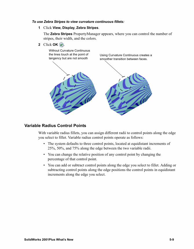
To use Zebra Stripes to view curvature continuous fillets:1 Click View, Display, Zebra Stripes.
The Zebra Stripes PropertyManager appears, where you can control the number of stripes, their width, and the colors.
2 Click OK .
Variable Radius Control PointsWith variable radius fillets, you can assign different radii to control points along the edge you select to fillet. Variable radius control points operate as follows:
• The system defaults to three control points, located at equidistant increments of 25%, 50%, and 75% along the edge between the two variable radii.
• You can change the relative position of any control point by changing the percentage of that control point.
• You can add or subtract control points along the edge you select to fillet. Adding or subtracting control points along the edge positions the control points in equidistant increments along the edge you select.
Using Curvature Continuous creates a smoother transition between faces.
Without Curvature Continuous the lines touch at the point of tangency but are not smooth
SolidWorks 2001Plus What’s New 5-9
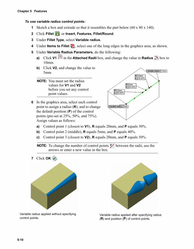
Chapter 5 Features
To use variable radius control points:1 Sketch a box and extrude so that it resembles the part below (60 x 80 x 140).2 Click Fillet , or Insert, Features, Fillet/Round.3 Under Fillet Type, select Variable radius.4 Under Items to Fillet , select one of the long edges in the graphics area, as shown.5 Under Variable Radius Parameters, do the following:
a) Click V1 in the Attached Radii box, and change the value in Radius box to 10mm.
b) Click V2, and change the value to 5mm
6 In the graphics area, select each control point to assign a radius (R), and to change the default position (P) of the control points (pre-set at 25%, 50%, and 75%). Assign values as follows:a) Control point 1 (closest to V1), R equals 20mm, and P equals 30%.b) Control point 2 (middle), R equals 5mm, and P equals 40%.c) Control point 3 (closest to V2), R equals 20mm, and P equals 50%.
7 Click OK .
NOTE: You must set the radius values for V1 and V2 before you set any control point values.
NOTE: To change the number of control points between the radii, use the arrows or enter a new value in the box.
Variable radius applied after specifying radius (R) and position (P) of control points.
Variable radius applied without specifying control points.
5-10
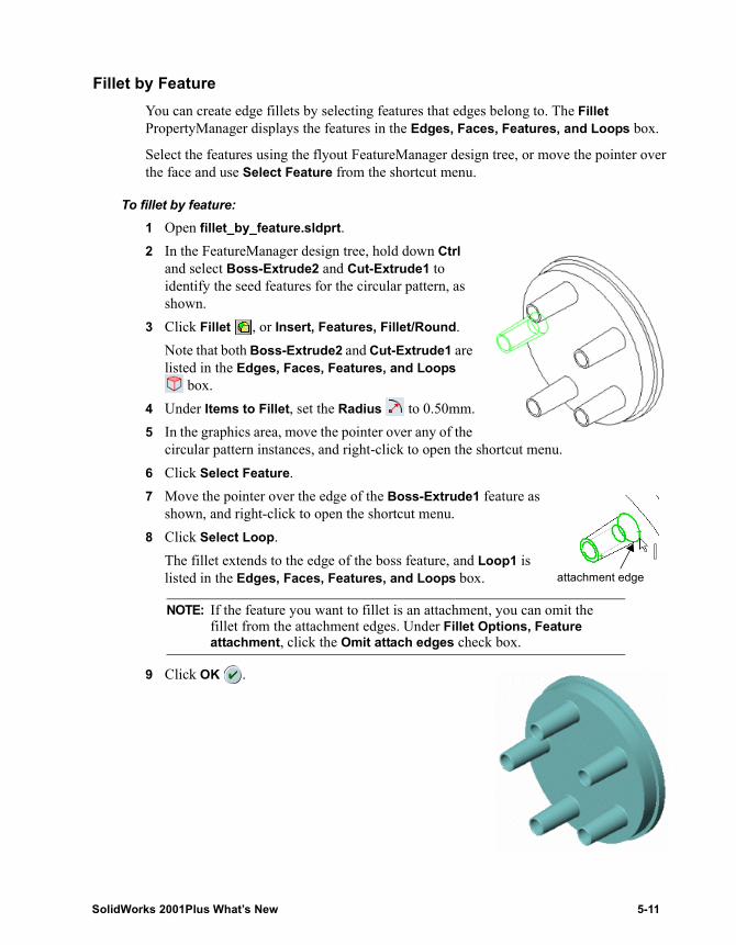
Fillet by FeatureYou can create edge fillets by selecting features that edges belong to. The Fillet PropertyManager displays the features in the Edges, Faces, Features, and Loops box.
Select the features using the flyout FeatureManager design tree, or move the pointer over the face and use Select Feature from the shortcut menu.
To fillet by feature:1 Open fillet_by_feature.sldprt.2 In the FeatureManager design tree, hold down Ctrl
and select Boss-Extrude2 and Cut-Extrude1 to identify the seed features for the circular pattern, as shown.
3 Click Fillet , or Insert, Features, Fillet/Round.Note that both Boss-Extrude2 and Cut-Extrude1 are listed in the Edges, Faces, Features, and Loops
box.4 Under Items to Fillet, set the Radius to 0.50mm.5 In the graphics area, move the pointer over any of the
circular pattern instances, and right-click to open the shortcut menu.6 Click Select Feature.7 Move the pointer over the edge of the Boss-Extrude1 feature as
shown, and right-click to open the shortcut menu.8 Click Select Loop.
The fillet extends to the edge of the boss feature, and Loop1 is listed in the Edges, Faces, Features, and Loops box.
9 Click OK .
NOTE: If the feature you want to fillet is an attachment, you can omit the fillet from the attachment edges. Under Fillet Options, Feature attachment, click the Omit attach edges check box.
attachment edge
SolidWorks 2001Plus What’s New 5-11
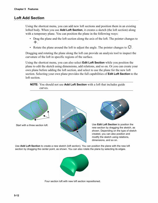
Chapter 5 Features
Loft Add Section
Using the shortcut menu, you can add new loft sections and position them in an existing lofted body. When you use Add Loft Section, it creates a sketch (the loft section) along with a temporary plane. You can position the plane in the following ways:
• Drag the plane and the loft section along the axis of the loft. The pointer changes to .
• Rotate the plane around the loft to adjust the angle. The pointer changes to .
Dragging and rotating the plane along the loft can provide an analysis tool to inspect the curvature of the loft in specific regions of the surface.
Using the shortcut menu, you can also select Edit Loft Section while you position the plane to edit the sketch using dimensions, add relations, and so on. Or you can create your own plane before adding the loft section, and select to use the plane for the new loft section. Selecting your own plane provides the full capabilities of Edit Loft Section to the loft section.
NOTE: You should not use Add Loft Section with a loft that includes guide curves.
Start with a three section loft.
Use Add Loft Section to create a new sketch (loft section). You can position the plane with the new loft section by dragging the center point, as shown. You can also rotate the plane by selecting its edges.
Use Edit Loft Section to position the new section by dragging the sketch, as shown. Depending on the type of sketch created, you can also position and modify the sketch using relations, dimensions, and so on.
Four section loft with new loft section repositioned.
5-12
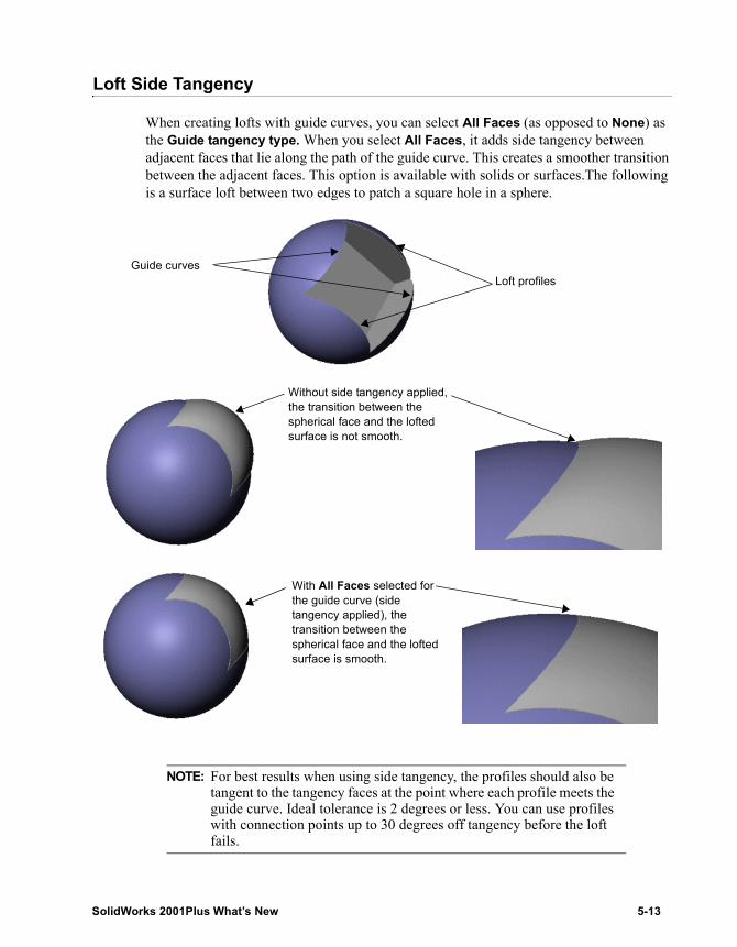
Loft Side Tangency
When creating lofts with guide curves, you can select All Faces (as opposed to None) as the Guide tangency type. When you select All Faces, it adds side tangency between adjacent faces that lie along the path of the guide curve. This creates a smoother transition between the adjacent faces. This option is available with solids or surfaces.The following is a surface loft between two edges to patch a square hole in a sphere.
NOTE: For best results when using side tangency, the profiles should also be tangent to the tangency faces at the point where each profile meets the guide curve. Ideal tolerance is 2 degrees or less. You can use profiles with connection points up to 30 degrees off tangency before the loft fails.
Without side tangency applied, the transition between the spherical face and the lofted surface is not smooth.
Guide curvesLoft profiles
With All Faces selected for the guide curve (side tangency applied), the transition between the spherical face and the lofted surface is smooth.
SolidWorks 2001Plus What’s New 5-13
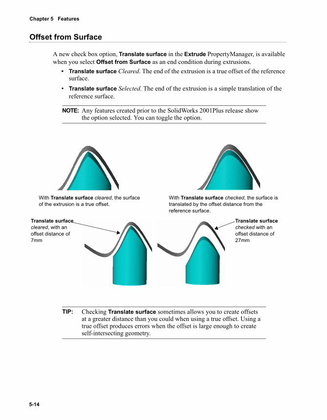
Chapter 5 Features
Offset from Surface
A new check box option, Translate surface in the Extrude PropertyManager, is available when you select Offset from Surface as an end condition during extrusions.
• Translate surface Cleared. The end of the extrusion is a true offset of the reference surface.
• Translate surface Selected. The end of the extrusion is a simple translation of the reference surface.
NOTE: Any features created prior to the SolidWorks 2001Plus release show the option selected. You can toggle the option.
TIP: Checking Translate surface sometimes allows you to create offsets at a greater distance than you could when using a true offset. Using a true offset produces errors when the offset is large enough to create self-intersecting geometry.
With Translate surface cleared, the surface of the extrusion is a true offset.
With Translate surface checked, the surface is translated by the offset distance from the reference surface.
Translate surface cleared, with an offset distance of 7mm
Translate surface checked with an offset distance of 27mm
5-14
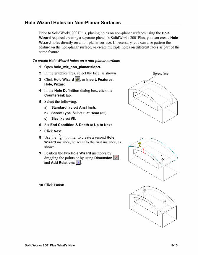
Hole Wizard Holes on Non-Planar Surfaces
Prior to SolidWorks 2001Plus, placing holes on non-planar surfaces using the Hole Wizard required creating a separate plane. In SolidWorks 2001Plus, you can create Hole Wizard holes directly on a non-planar surface. If necessary, you can also pattern the feature on the non-planar surface, or create multiple holes on different faces as part of the same feature.
To create Hole Wizard holes on a non-planar surface:1 Open hole_wiz_non_planar.sldprt.2 In the graphics area, select the face, as shown.3 Click Hole Wizard , or Insert, Features,
Hole, Wizard.4 In the Hole Definition dialog box, click the
Countersink tab.5 Select the following:
a) Standard. Select Ansi Inch.b) Screw Type. Select Flat Head (82).c) Size. Select #8.
6 Set End Condition & Depth to Up to Next.7 Click Next.8 Use the pointer to create a second Hole
Wizard instance, adjacent to the first instance, as shown.
9 Position the two Hole Wizard instances by dragging the points or by using Dimension and Add Relations .
10 Click Finish.
Select face
SolidWorks 2001Plus What’s New 5-15
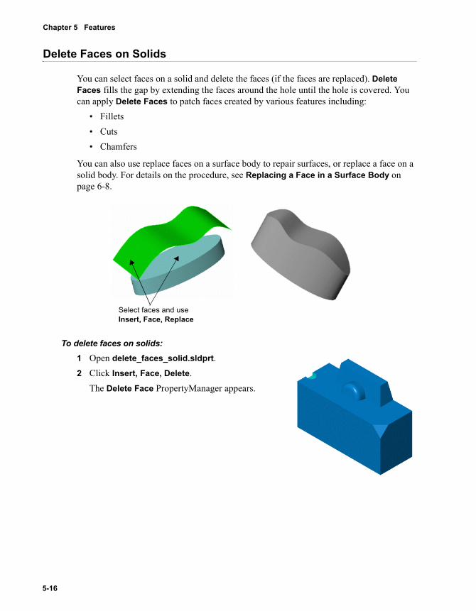
Chapter 5 Features
Delete Faces on Solids
You can select faces on a solid and delete the faces (if the faces are replaced). Delete Faces fills the gap by extending the faces around the hole until the hole is covered. You can apply Delete Faces to patch faces created by various features including:
• Fillets• Cuts• Chamfers
You can also use replace faces on a surface body to repair surfaces, or replace a face on a solid body. For details on the procedure, see Replacing a Face in a Surface Body on page 6-8.
To delete faces on solids:1 Open delete_faces_solid.sldprt.2 Click Insert, Face, Delete.
The Delete Face PropertyManager appears.
Select faces and use Insert, Face, Replace
5-16
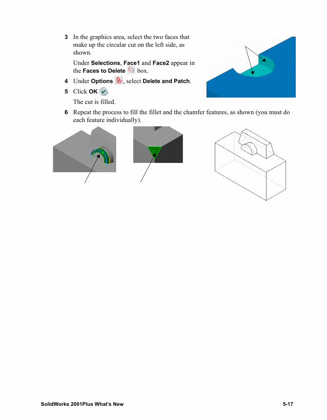
3 In the graphics area, select the two faces that make up the circular cut on the left side, as shown.Under Selections, Face1 and Face2 appear in the Faces to Delete box.
4 Under Options , select Delete and Patch.5 Click OK .
The cut is filled.6 Repeat the process to fill the fillet and the chamfer features, as shown (you must do
each feature individually).
SolidWorks 2001Plus What’s New 5-17
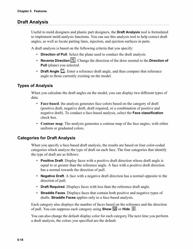
Chapter 5 Features
Draft Analysis
Useful to mold designers and plastic part designers, the Draft Analysis tool is formulated to implement mold analysis functions. You can use this analysis tool to help correct draft angles, as well as locate parting lines, injection, and ejection surfaces in parts.
A draft analysis is based on the following criteria that you specify:• Direction of Pull. Select the plane used to conduct the draft analysis. • Reverse Direction . Change the direction of the draw normal to the Direction of
Pull (plane) you selected.• Draft Angle . Enter a reference draft angle, and then compare that reference
angle to those currently existing on the model.
Types of AnalysisWhen you calculate the draft angles on the model, you can display two different types of data.
• Face-based. the analysis generates face colors based on the category of draft (positive draft, negative draft, draft required, or a combination of positive and negative draft). To conduct a face-based analysis, select the Face classification check box.
• Contour map. The analysis generates a contour map of the face angles, with either uniform or graduated colors.
Categories for Draft AnalysisWhen you specify a face-based draft analysis, the results are based on four color-coded categories which analyze the type of draft on each face. The four categories that identify the type of draft are as follows:
• Positive Draft. Display faces with a positive draft direction whose draft angle is equal to or greater than the reference angle. A face with a positive draft direction has a normal towards the direction of pull.
• Negative Draft. A face with a negative draft direction has a normal opposite to the direction of pull.
• Draft Required. Displays faces with less than the reference draft angle.• Straddle Faces. Displays faces that contain both positive and negative types of
drafts. Straddle Faces applies only to a face-based analysis.
Each category also displays the number of faces based on the reference and the direction of pull. You can suppress each category using Show or Hide .
You can also change the default display color for each category.The next time you perform a draft analysis, the colors you specified are the default.
5-18
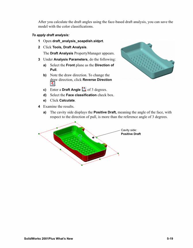
After you calculate the draft angles using the face-based draft analysis, you can save the model with the color classifications.
To apply draft analysis:1 Open draft_analysis_soapdish.sldprt.2 Click Tools, Draft Analysis.
The Draft Analysis PropertyManager appears.3 Under Analysis Parameters, do the following:
a) Select the Front plane as the Direction of Pull.
b) Note the draw direction. To change the draw direction, click Reverse Direction
.c) Enter a Draft Angle of 3 degrees.d) Select the Face classification check box.e) Click Calculate.
4 Examine the results.a) The cavity side displays the Positive Draft, meaning the angle of the face, with
respect to the direction of pull, is more than the reference angle of 3 degrees.
Cavity side:Positive Draft
SolidWorks 2001Plus What’s New 5-19
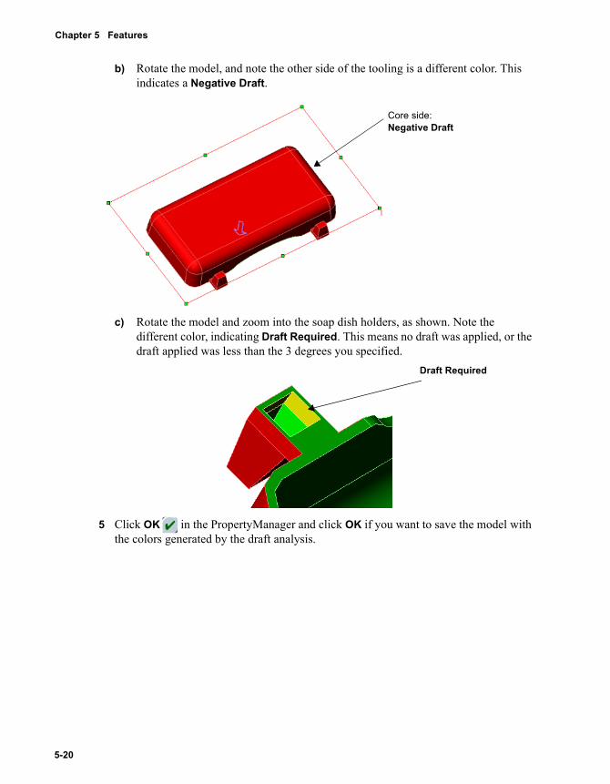
Chapter 5 Features
b) Rotate the model, and note the other side of the tooling is a different color. This indicates a Negative Draft.
c) Rotate the model and zoom into the soap dish holders, as shown. Note the different color, indicating Draft Required. This means no draft was applied, or the draft applied was less than the 3 degrees you specified.
5 Click OK in the PropertyManager and click OK if you want to save the model with the colors generated by the draft analysis.
Core side:Negative Draft
Draft Required
5-20
6 Parts and Surfaces
The 3D part is the basic building block of the SolidWorks mechanical design software. Surfaces are zero-thickness geometry that can be used to create solids. Changes include the following:
� Split part
� Section view selection
� Zebra stripes
� New functions in PropertyManager
� Mirror surfaces
� Delete face
� Replace face
SolidWorks 2001Plus What’s New 6-1
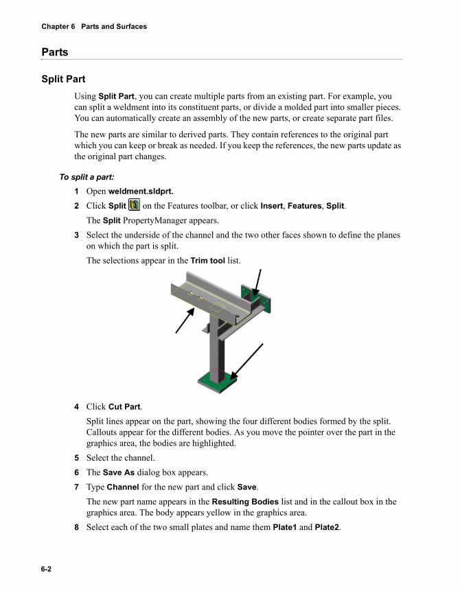
Chapter 6 Parts and Surfaces
Parts
Split PartUsing Split Part, you can create multiple parts from an existing part. For example, you can split a weldment into its constituent parts, or divide a molded part into smaller pieces. You can automatically create an assembly of the new parts, or create separate part files.
The new parts are similar to derived parts. They contain references to the original part which you can keep or break as needed. If you keep the references, the new parts update as the original part changes.
To split a part:1 Open weldment.sldprt.2 Click Split on the Features toolbar, or click Insert, Features, Split.
The Split PropertyManager appears.3 Select the underside of the channel and the two other faces shown to define the planes
on which the part is split.The selections appear in the Trim tool list.
4 Click Cut Part. Split lines appear on the part, showing the four different bodies formed by the split. Callouts appear for the different bodies. As you move the pointer over the part in the graphics area, the bodies are highlighted.
5 Select the channel.6 The Save As dialog box appears.7 Type Channel for the new part and click Save.
The new part name appears in the Resulting Bodies list and in the callout box in the graphics area. The body appears yellow in the graphics area.
8 Select each of the two small plates and name them Plate1 and Plate2.
6-2
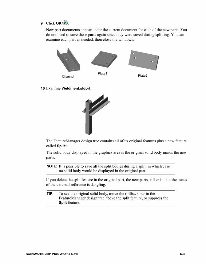
9 Click OK .New part documents appear under the current document for each of the new parts. You do not need to save these parts again since they were saved during splitting. You can examine each part as needed, then close the windows.
10 Examine Weldment.sldprt.
The FeatureManager design tree contains all of its original features plus a new feature called Split1.The solid body displayed in the graphics area is the original solid body minus the new parts.
If you delete the split feature in the original part, the new parts still exist, but the status of the external reference is dangling.
NOTE: It is possible to save all the split bodies during a split, in which case no solid body would be displayed in the original part.
TIP: To see the original solid body, move the rollback bar in the FeatureManager design tree above the split feature, or suppress the Split feature.
ChannelPlate1 Plate2
SolidWorks 2001Plus What’s New 6-3
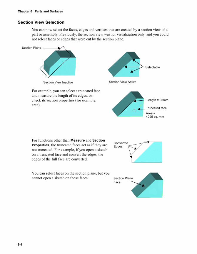
Chapter 6 Parts and Surfaces
Section View SelectionYou can now select the faces, edges and vertices that are created by a section view of a part or assembly. Previously, the section view was for visualization only, and you could not select faces or edges that were cut by the section plane.
For example, you can select a truncated face and measure the length of its edges, or check its section properties (for example, area).
For functions other than Measure and Section Properties, the truncated faces act as if they are not truncated. For example, if you open a sketch on a truncated face and convert the edges, the edges of the full face are converted.
You can select faces on the section plane, but you cannot open a sketch on those faces.
Selectable
Section View ActiveSection View Inactive
Section Plane
Area =
Length = 95mm
Truncated face
4095 sq. mm
ConvertedEdges
Section Plane Face
6-4
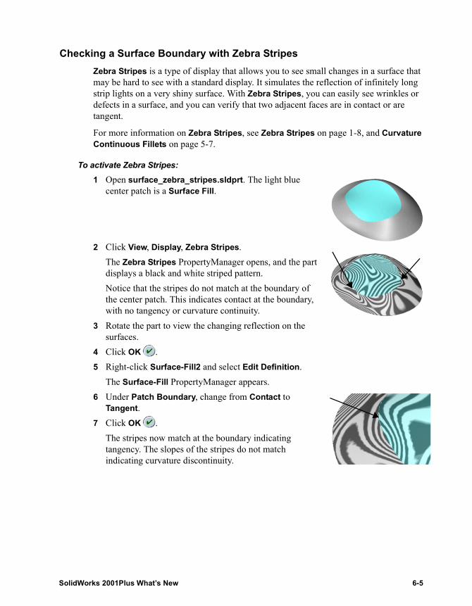
Checking a Surface Boundary with Zebra StripesZebra Stripes is a type of display that allows you to see small changes in a surface that may be hard to see with a standard display. It simulates the reflection of infinitely long strip lights on a very shiny surface. With Zebra Stripes, you can easily see wrinkles or defects in a surface, and you can verify that two adjacent faces are in contact or are tangent.
For more information on Zebra Stripes, see Zebra Stripes on page 1-8, and Curvature Continuous Fillets on page 5-7.
To activate Zebra Stripes:1 Open surface_zebra_stripes.sldprt. The light blue
center patch is a Surface Fill.
2 Click View, Display, Zebra Stripes.The Zebra Stripes PropertyManager opens, and the part displays a black and white striped pattern.Notice that the stripes do not match at the boundary of the center patch. This indicates contact at the boundary, with no tangency or curvature continuity.
3 Rotate the part to view the changing reflection on the surfaces.
4 Click OK .5 Right-click Surface-Fill2 and select Edit Definition.
The Surface-Fill PropertyManager appears.6 Under Patch Boundary, change from Contact to
Tangent.7 Click OK .
The stripes now match at the boundary indicating tangency. The slopes of the stripes do not match indicating curvature discontinuity.
SolidWorks 2001Plus What’s New 6-5
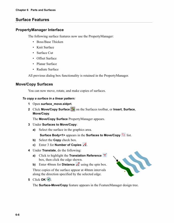
Chapter 6 Parts and Surfaces
Surface Features
PropertyManager InterfaceThe following surface features now use the PropertyManager:
• Boss/Base Thicken• Knit Surface• Surface Cut• Offset Surface• Planar Surface• Radiate Surface
All previous dialog box functionality is retained in the PropertyManager.
Move/Copy SurfacesYou can now move, rotate, and make copies of surfaces.
To copy a surface in a linear pattern:1 Open surface_move.sldprt.2 Click Move/Copy Surface on the Surfaces toolbar, or Insert, Surface,
Move/Copy.The Move/Copy Surface PropertyManager appears.
3 Under Surfaces to Move/Copy:a) Select the surface in the graphics area.
Surface Body<1> appears in the Surfaces to Move/Copy list.b) Select the Copy check box.c) Enter 3 for Number of Copies .
4 Under Translate, do the following:a) Click to highlight the Translation Reference
box, then click the edge shown.b) Enter 40mm for Distance using the spin box.Three copies of the surface appear at 40mm intervals along the direction specified by the selected edge.
5 Click OK .The Surface-Move/Copy feature appears in the FeatureManager design tree.
6-6
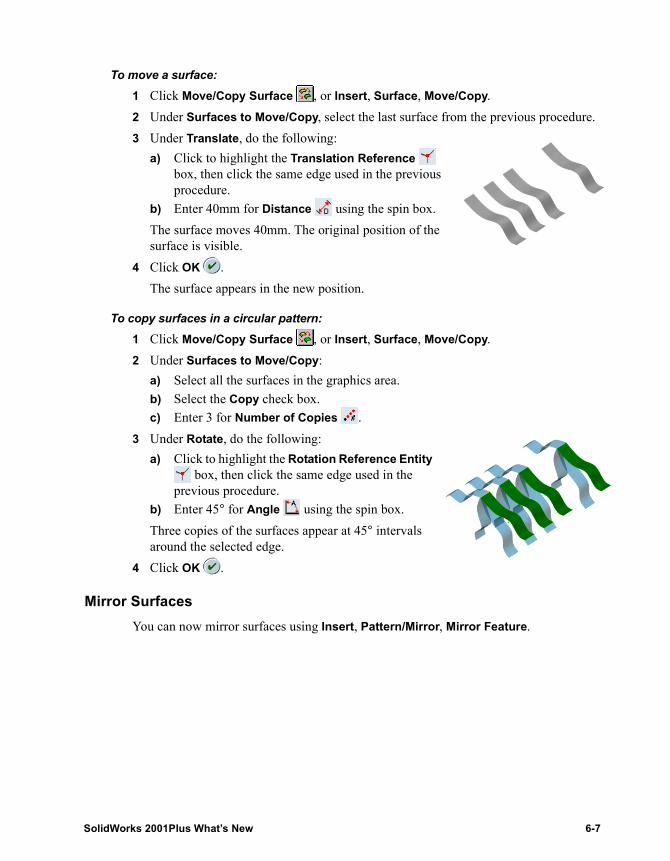
To move a surface:1 Click Move/Copy Surface , or Insert, Surface, Move/Copy.2 Under Surfaces to Move/Copy, select the last surface from the previous procedure.3 Under Translate, do the following:
a) Click to highlight the Translation Reference box, then click the same edge used in the previous procedure.
b) Enter 40mm for Distance using the spin box.The surface moves 40mm. The original position of the surface is visible.
4 Click OK .The surface appears in the new position.
To copy surfaces in a circular pattern:1 Click Move/Copy Surface , or Insert, Surface, Move/Copy.2 Under Surfaces to Move/Copy:
a) Select all the surfaces in the graphics area.b) Select the Copy check box.c) Enter 3 for Number of Copies .
3 Under Rotate, do the following:a) Click to highlight the Rotation Reference Entity
box, then click the same edge used in the previous procedure.
b) Enter 45° for Angle using the spin box.Three copies of the surfaces appear at 45° intervals around the selected edge.
4 Click OK .
Mirror SurfacesYou can now mirror surfaces using Insert, Pattern/Mirror, Mirror Feature.
SolidWorks 2001Plus What’s New 6-7
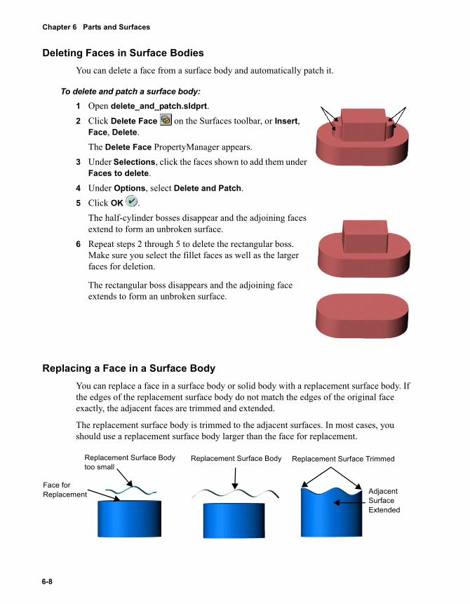
Chapter 6 Parts and Surfaces
Deleting Faces in Surface BodiesYou can delete a face from a surface body and automatically patch it.
To delete and patch a surface body:1 Open delete_and_patch.sldprt.2 Click Delete Face on the Surfaces toolbar, or Insert,
Face, Delete.The Delete Face PropertyManager appears.
3 Under Selections, click the faces shown to add them under Faces to delete.
4 Under Options, select Delete and Patch.5 Click OK .
The half-cylinder bosses disappear and the adjoining faces extend to form an unbroken surface.
6 Repeat steps 2 through 5 to delete the rectangular boss. Make sure you select the fillet faces as well as the larger faces for deletion.
The rectangular boss disappears and the adjoining face extends to form an unbroken surface.
Replacing a Face in a Surface BodyYou can replace a face in a surface body or solid body with a replacement surface body. If the edges of the replacement surface body do not match the edges of the original face exactly, the adjacent faces are trimmed and extended.
The replacement surface body is trimmed to the adjacent surfaces. In most cases, you should use a replacement surface body larger than the face for replacement.
Replacement Surface Body
Face for Replacement Adjacent
Surface Extended
Replacement Surface TrimmedReplacement Surface Body too small
6-8
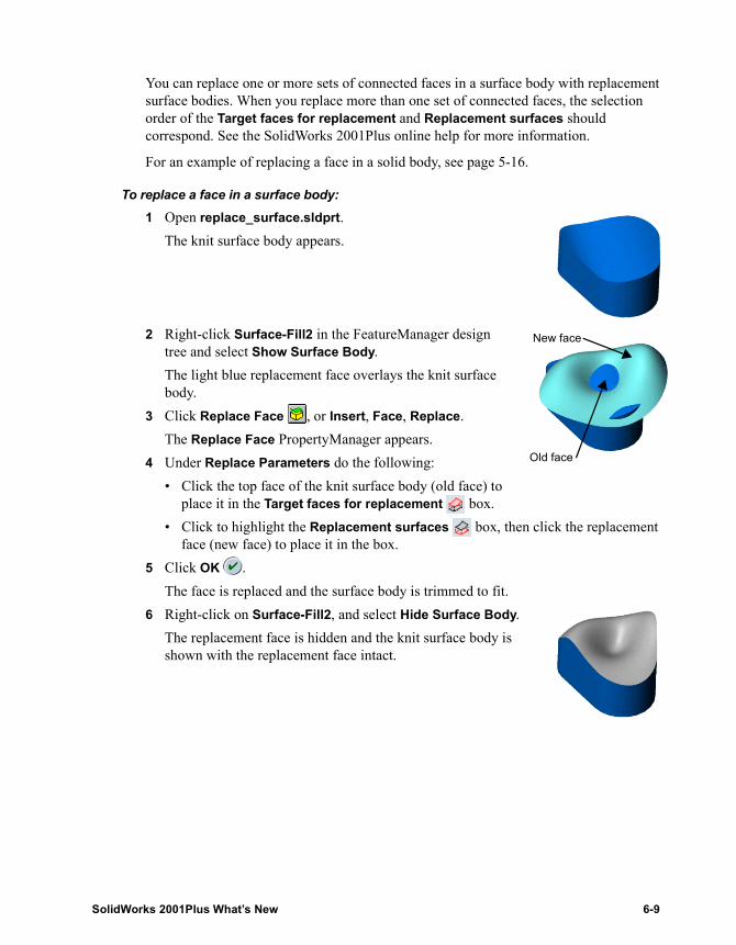
You can replace one or more sets of connected faces in a surface body with replacement surface bodies. When you replace more than one set of connected faces, the selection order of the Target faces for replacement and Replacement surfaces should correspond. See the SolidWorks 2001Plus online help for more information.
For an example of replacing a face in a solid body, see page 5-16.
To replace a face in a surface body:1 Open replace_surface.sldprt.
The knit surface body appears.
2 Right-click Surface-Fill2 in the FeatureManager design tree and select Show Surface Body.The light blue replacement face overlays the knit surface body.
3 Click Replace Face , or Insert, Face, Replace.The Replace Face PropertyManager appears.
4 Under Replace Parameters do the following:• Click the top face of the knit surface body (old face) to
place it in the Target faces for replacement box.• Click to highlight the Replacement surfaces box, then click the replacement
face (new face) to place it in the box.5 Click OK .
The face is replaced and the surface body is trimmed to fit. 6 Right-click on Surface-Fill2, and select Hide Surface Body.
The replacement face is hidden and the knit surface body is shown with the replacement face intact.
New face
Old face
SolidWorks 2001Plus What’s New 6-9
7 Assemblies
This chapter describes general information about working with assemblies of any kind. The following enhancements are discussed:
� Enhanced mate selections
� Diagnosing mate problems
� Moving and rotating multiple components
� Mirror components interface
� Explode lines
� Selection of interior parts
� Transparency in assemblies
� Large assembly performance
� Physical Dynamics
� MateGroup consolidation
SolidWorks 2001Plus What’s New 7-1
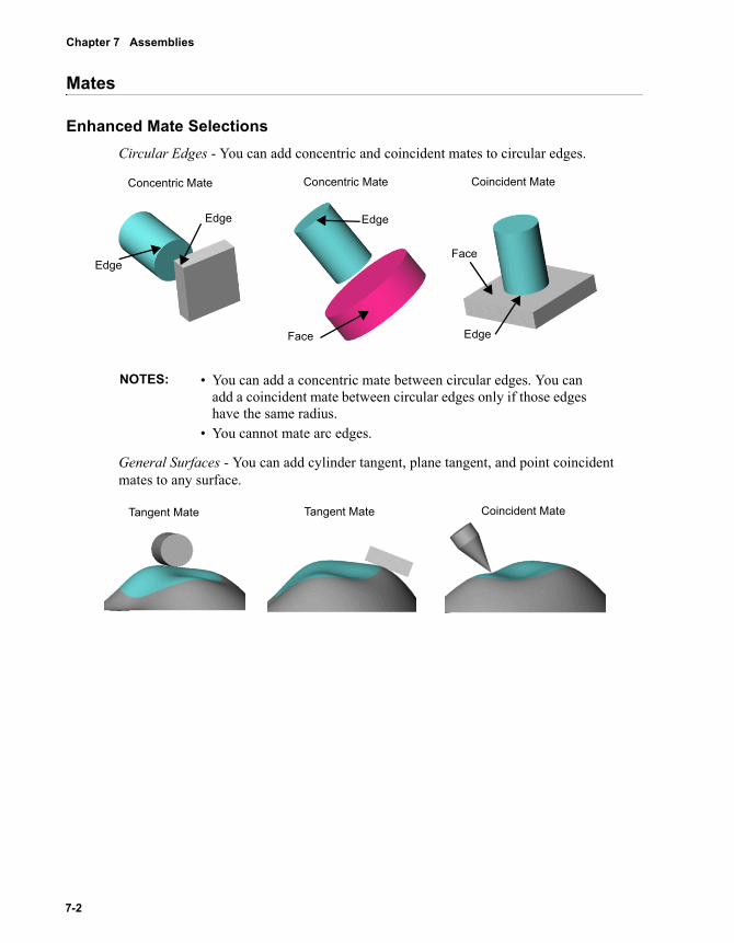
Chapter 7 Assemblies
Mates
Enhanced Mate SelectionsCircular Edges - You can add concentric and coincident mates to circular edges.
General Surfaces - You can add cylinder tangent, plane tangent, and point coincident mates to any surface.
NOTES: • You can add a concentric mate between circular edges. You can add a coincident mate between circular edges only if those edges have the same radius.
• You cannot mate arc edges.
Coincident MateConcentric Mate Concentric Mate
Edge
Edge
Edge
Face Edge
Face
Tangent Mate Tangent Mate Coincident Mate
7-2
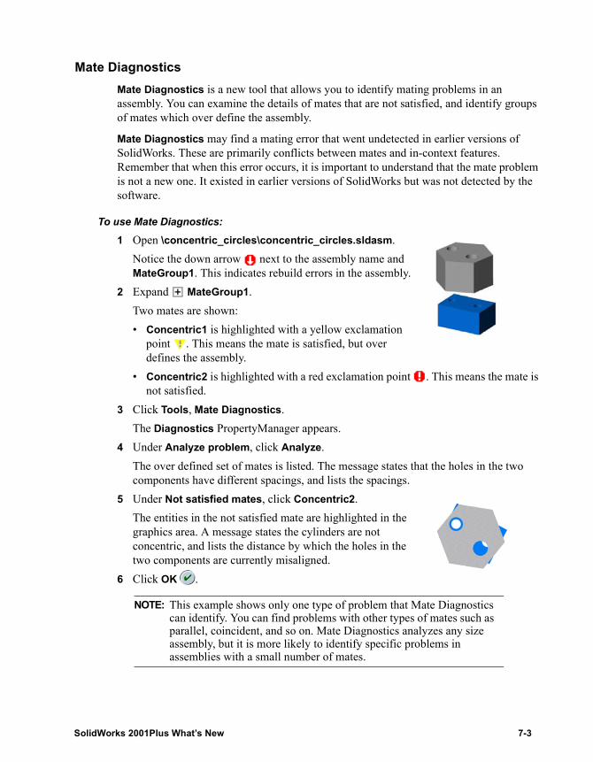
Mate DiagnosticsMate Diagnostics is a new tool that allows you to identify mating problems in an assembly. You can examine the details of mates that are not satisfied, and identify groups of mates which over define the assembly.
Mate Diagnostics may find a mating error that went undetected in earlier versions of SolidWorks. These are primarily conflicts between mates and in-context features. Remember that when this error occurs, it is important to understand that the mate problem is not a new one. It existed in earlier versions of SolidWorks but was not detected by the software.
To use Mate Diagnostics:1 Open \concentric_circles\concentric_circles.sldasm.
Notice the down arrow next to the assembly name and MateGroup1. This indicates rebuild errors in the assembly.
2 Expand MateGroup1.Two mates are shown:• Concentric1 is highlighted with a yellow exclamation
point . This means the mate is satisfied, but over defines the assembly.
• Concentric2 is highlighted with a red exclamation point . This means the mate is not satisfied.
3 Click Tools, Mate Diagnostics.The Diagnostics PropertyManager appears.
4 Under Analyze problem, click Analyze.The over defined set of mates is listed. The message states that the holes in the two components have different spacings, and lists the spacings.
5 Under Not satisfied mates, click Concentric2.The entities in the not satisfied mate are highlighted in the graphics area. A message states the cylinders are not concentric, and lists the distance by which the holes in the two components are currently misaligned.
6 Click OK .
NOTE: This example shows only one type of problem that Mate Diagnostics can identify. You can find problems with other types of mates such as parallel, coincident, and so on. Mate Diagnostics analyzes any size assembly, but it is more likely to identify specific problems in assemblies with a small number of mates.
SolidWorks 2001Plus What’s New 7-3
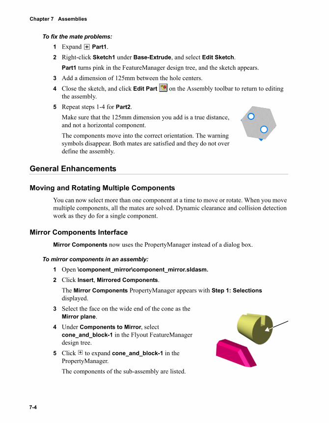
Chapter 7 Assemblies
To fix the mate problems:1 Expand Part1.2 Right-click Sketch1 under Base-Extrude, and select Edit Sketch.
Part1 turns pink in the FeatureManager design tree, and the sketch appears.3 Add a dimension of 125mm between the hole centers.4 Close the sketch, and click Edit Part on the Assembly toolbar to return to editing
the assembly.5 Repeat steps 1-4 for Part2.
Make sure that the 125mm dimension you add is a true distance, and not a horizontal component.The components move into the correct orientation. The warning symbols disappear. Both mates are satisfied and they do not over define the assembly.
General Enhancements
Moving and Rotating Multiple ComponentsYou can now select more than one component at a time to move or rotate. When you move multiple components, all the mates are solved. Dynamic clearance and collision detection work as they do for a single component.
Mirror Components InterfaceMirror Components now uses the PropertyManager instead of a dialog box.
To mirror components in an assembly:1 Open \component_mirror\component_mirror.sldasm.2 Click Insert, Mirrored Components.
The Mirror Components PropertyManager appears with Step 1: Selections displayed.
3 Select the face on the wide end of the cone as the Mirror plane.
4 Under Components to Mirror, select cone_and_block-1 in the Flyout FeatureManager design tree.
5 Click to expand cone_and_block-1 in the PropertyManager.The components of the sub-assembly are listed.
7-4
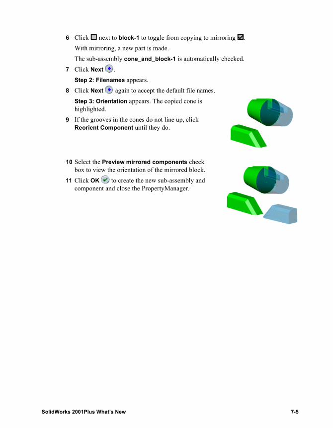
6 Click next to block-1 to toggle from copying to mirroring . With mirroring, a new part is made.The sub-assembly cone_and_block-1 is automatically checked.
7 Click Next .Step 2: Filenames appears.
8 Click Next again to accept the default file names.Step 3: Orientation appears. The copied cone is highlighted.
9 If the grooves in the cones do not line up, click Reorient Component until they do.
10 Select the Preview mirrored components check box to view the orientation of the mirrored block.
11 Click OK to create the new sub-assembly and component and close the PropertyManager.
SolidWorks 2001Plus What’s New 7-5
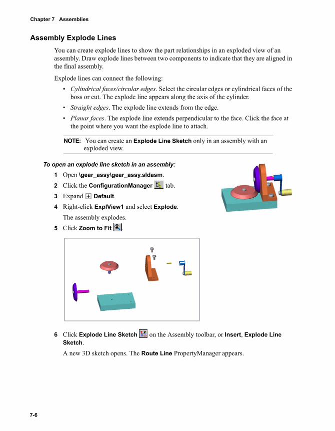
Chapter 7 Assemblies
Assembly Explode LinesYou can create explode lines to show the part relationships in an exploded view of an assembly. Draw explode lines between two components to indicate that they are aligned in the final assembly.
Explode lines can connect the following:• Cylindrical faces/circular edges. Select the circular edges or cylindrical faces of the
boss or cut. The explode line appears along the axis of the cylinder.• Straight edges. The explode line extends from the edge.• Planar faces. The explode line extends perpendicular to the face. Click the face at
the point where you want the explode line to attach.
To open an explode line sketch in an assembly:1 Open \gear_assy\gear_assy.sldasm.2 Click the ConfigurationManager tab.3 Expand Default.4 Right-click ExplView1 and select Explode.
The assembly explodes.5 Click Zoom to Fit .
6 Click Explode Line Sketch on the Assembly toolbar, or Insert, Explode Line Sketch.A new 3D sketch opens. The Route Line PropertyManager appears.
NOTE: You can create an Explode Line Sketch only in an assembly with an exploded view.
7-6
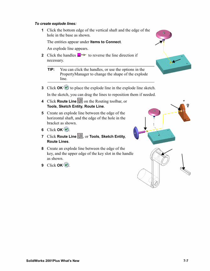
To create explode lines:1 Click the bottom edge of the vertical shaft and the edge of the
hole in the base as shown.The entities appear under Items to Connect.An explode line appears.
2 Click the handles to reverse the line direction if necessary.
3 Click OK to place the explode line in the explode line sketch. In the sketch, you can drag the lines to reposition them if needed.
4 Click Route Line on the Routing toolbar, or Tools, Sketch Entity, Route Line.
5 Create an explode line between the edge of the horizontal shaft, and the edge of the hole in the bracket as shown.
6 Click OK .7 Click Route Line , or Tools, Sketch Entity,
Route Lines.
8 Create an explode line between the edge of the key, and the upper edge of the key slot in the handle as shown.
9 Click OK .
TIP: You can click the handles, or use the options in the PropertyManager to change the shape of the explode line.
SolidWorks 2001Plus What’s New 7-7
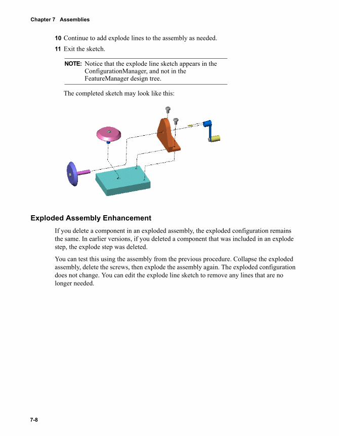
Chapter 7 Assemblies
10 Continue to add explode lines to the assembly as needed.11 Exit the sketch.
The completed sketch may look like this:
Exploded Assembly EnhancementIf you delete a component in an exploded assembly, the exploded configuration remains the same. In earlier versions, if you deleted a component that was included in an explode step, the explode step was deleted.
You can test this using the assembly from the previous procedure. Collapse the exploded assembly, delete the screws, then explode the assembly again. The exploded configuration does not change. You can edit the explode line sketch to remove any lines that are no longer needed.
NOTE: Notice that the explode line sketch appears in the ConfigurationManager, and not in the FeatureManager design tree.
7-8
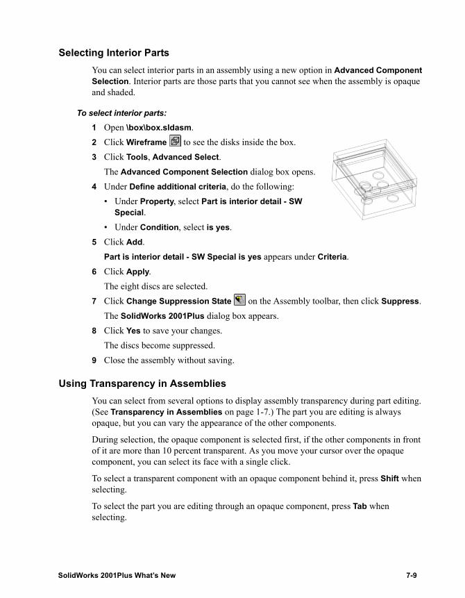
Selecting Interior PartsYou can select interior parts in an assembly using a new option in Advanced Component Selection. Interior parts are those parts that you cannot see when the assembly is opaque and shaded.
To select interior parts:1 Open \box\box.sldasm.2 Click Wireframe to see the disks inside the box.3 Click Tools, Advanced Select.
The Advanced Component Selection dialog box opens.4 Under Define additional criteria, do the following:
• Under Property, select Part is interior detail - SW Special.
• Under Condition, select is yes.5 Click Add.
Part is interior detail - SW Special is yes appears under Criteria.6 Click Apply.
The eight discs are selected.7 Click Change Suppression State on the Assembly toolbar, then click Suppress.
The SolidWorks 2001Plus dialog box appears.8 Click Yes to save your changes.
The discs become suppressed.9 Close the assembly without saving.
Using Transparency in AssembliesYou can select from several options to display assembly transparency during part editing. (See Transparency in Assemblies on page 1-7.) The part you are editing is always opaque, but you can vary the appearance of the other components.
During selection, the opaque component is selected first, if the other components in front of it are more than 10 percent transparent. As you move your cursor over the opaque component, you can select its face with a single click.
To select a transparent component with an opaque component behind it, press Shift when selecting.
To select the part you are editing through an opaque component, press Tab when selecting.
SolidWorks 2001Plus What’s New 7-9
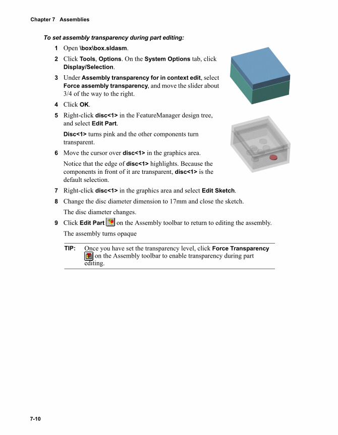
Chapter 7 Assemblies
To set assembly transparency during part editing:1 Open \box\box.sldasm.2 Click Tools, Options. On the System Options tab, click
Display/Selection.3 Under Assembly transparency for in context edit, select
Force assembly transparency, and move the slider about 3/4 of the way to the right.
4 Click OK.5 Right-click disc<1> in the FeatureManager design tree,
and select Edit Part.Disc<1> turns pink and the other components turn transparent.
6 Move the cursor over disc<1> in the graphics area. Notice that the edge of disc<1> highlights. Because the components in front of it are transparent, disc<1> is the default selection.
7 Right-click disc<1> in the graphics area and select Edit Sketch.8 Change the disc diameter dimension to 17mm and close the sketch.
The disc diameter changes.9 Click Edit Part on the Assembly toolbar to return to editing the assembly.
The assembly turns opaque
TIP: Once you have set the transparency level, click Force Transparency on the Assembly toolbar to enable transparency during part
editing.
7-10
Large Assembly ModeLarge Assembly Mode allows you to specify various performance-related options that apply only to large assemblies.
To specify Large Assembly Mode options:1 Click Tools, Options. On the System Options tab, click Large Assembly Settings.
The options appear pre-set with recommended settings for use with large assemblies.Large assembly threshold is the number of components above which Large Assembly Mode activates or sends a message, depending on your settings.
2 In the Automatically activate Large Assembly Mode list, select from the following:• Prompt. When you reach the threshold, a message appears with the option to
activate Large Assembly Mode.• Never. Ignores the threshold.• Always. When you reach the threshold, Large Assembly Mode automatically
activates.3 Modify any of the other settings as needed.
Many of the options also appear in other areas of the Options dialog box. The settings you choose under Large Assembly Settings apply only when you are in Large Assembly Mode. Options that you set elsewhere apply when Large Assembly Mode is off.
4 Click OK.
To activate Large Assembly Mode:Click Large Assembly Mode on the Assembly toolbar, or click Tools, Large Assembly Mode.-or-Set the threshold settings as described previously to activate Large Assembly Mode when the number of components in your assembly reaches the specified threshold.
SolidWorks 2001Plus What’s New 7-11
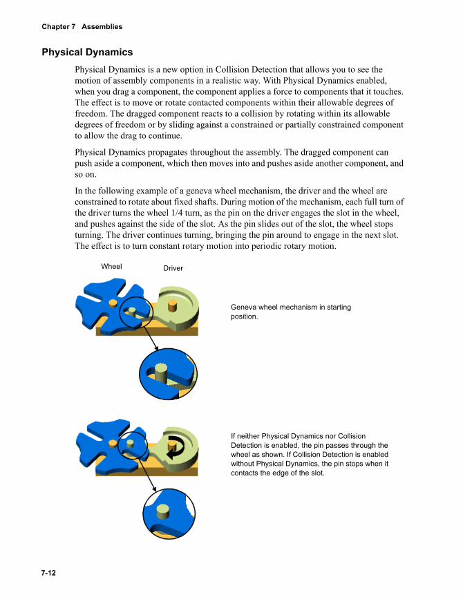
Chapter 7 Assemblies
Physical DynamicsPhysical Dynamics is a new option in Collision Detection that allows you to see the motion of assembly components in a realistic way. With Physical Dynamics enabled, when you drag a component, the component applies a force to components that it touches. The effect is to move or rotate contacted components within their allowable degrees of freedom. The dragged component reacts to a collision by rotating within its allowable degrees of freedom or by sliding against a constrained or partially constrained component to allow the drag to continue.
Physical Dynamics propagates throughout the assembly. The dragged component can push aside a component, which then moves into and pushes aside another component, and so on.
In the following example of a geneva wheel mechanism, the driver and the wheel are constrained to rotate about fixed shafts. During motion of the mechanism, each full turn of the driver turns the wheel 1/4 turn, as the pin on the driver engages the slot in the wheel, and pushes against the side of the slot. As the pin slides out of the slot, the wheel stops turning. The driver continues turning, bringing the pin around to engage in the next slot. The effect is to turn constant rotary motion into periodic rotary motion.
Geneva wheel mechanism in starting position.
If neither Physical Dynamics nor Collision Detection is enabled, the pin passes through the wheel as shown. If Collision Detection is enabled without Physical Dynamics, the pin stops when it contacts the edge of the slot.
Wheel Driver
7-12
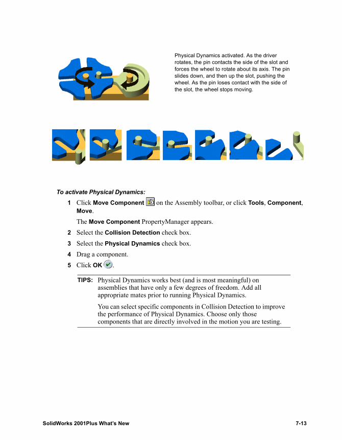
To activate Physical Dynamics:1 Click Move Component on the Assembly toolbar, or click Tools, Component,
Move.The Move Component PropertyManager appears.
2 Select the Collision Detection check box.3 Select the Physical Dynamics check box.4 Drag a component.5 Click OK .
TIPS: Physical Dynamics works best (and is most meaningful) on assemblies that have only a few degrees of freedom. Add all appropriate mates prior to running Physical Dynamics.
You can select specific components in Collision Detection to improve the performance of Physical Dynamics. Choose only those components that are directly involved in the motion you are testing.
Physical Dynamics activated. As the driver rotates, the pin contacts the side of the slot and forces the wheel to rotate about its axis. The pin slides down, and then up the slot, pushing the wheel. As the pin loses contact with the side of the slot, the wheel stops moving.
SolidWorks 2001Plus What’s New 7-13
Chapter 7 Assemblies
MateGroup ConsolidationIn earlier versions of SolidWorks, an assembly could have more than one mategroup. In SolidWorks 2001Plus, each assembly contains only one mategroup. The program solves all the mates together.
When you save an existing assembly with multiple mategroups in SolidWorks 2001Plus, the software consolidates all the mates in that assembly into a single mategroup. The other mategroups no longer appear in the FeatureManager design tree.
There are several advantages to solving all the mates in a single mategroup:• Improved drag behavior. The program solves all mates during a drag. In earlier
versions of SolidWorks, not all mates were solved during a drag. It depended on which mategroups the dragged component referenced.
• No mategroup propagation. All mates are created in and stay in MateGroup1. In earlier versions, you could not create some types of mates until an existing group of mates moved to a new mategroup.
• Fewer mating errors. You can create some mates to assembly-level features that previously were not possible.
7-14
8 Configurations
� You can set the following items with different values in specified configurations:• Individual features• End conditions• Sketch planes• Equations• Sketch constraints• Sketch dimensions• External sketch relations
� Other new functionality in configurations include:• Nested configurations• Design table icon
SolidWorks 2001Plus What’s New 8-1
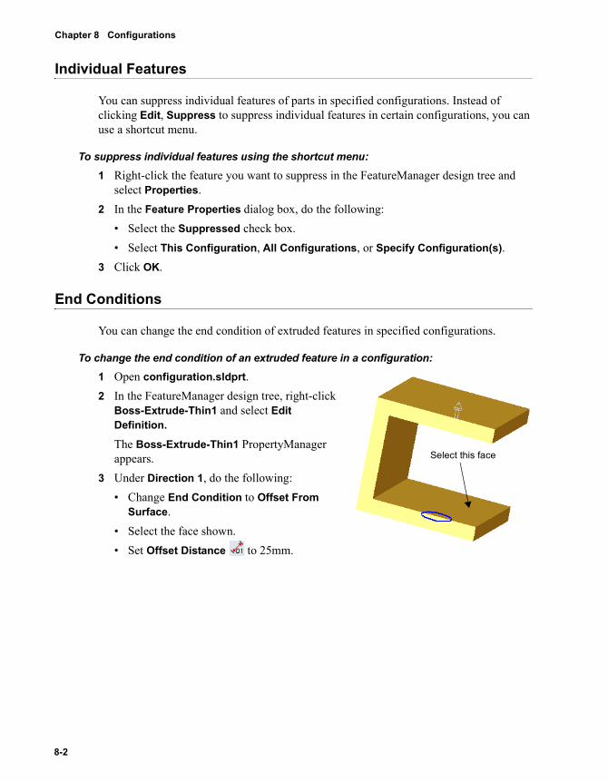
Chapter 8 Configurations
Individual Features
You can suppress individual features of parts in specified configurations. Instead of clicking Edit, Suppress to suppress individual features in certain configurations, you can use a shortcut menu.
To suppress individual features using the shortcut menu:1 Right-click the feature you want to suppress in the FeatureManager design tree and
select Properties.2 In the Feature Properties dialog box, do the following:
• Select the Suppressed check box.• Select This Configuration, All Configurations, or Specify Configuration(s).
3 Click OK.
End Conditions
You can change the end condition of extruded features in specified configurations.
To change the end condition of an extruded feature in a configuration:1 Open configuration.sldprt.2 In the FeatureManager design tree, right-click
Boss-Extrude-Thin1 and select Edit Definition.
The Boss-Extrude-Thin1 PropertyManager appears.
3 Under Direction 1, do the following:• Change End Condition to Offset From
Surface.• Select the face shown.• Set Offset Distance to 25mm.
Select this face
8-2
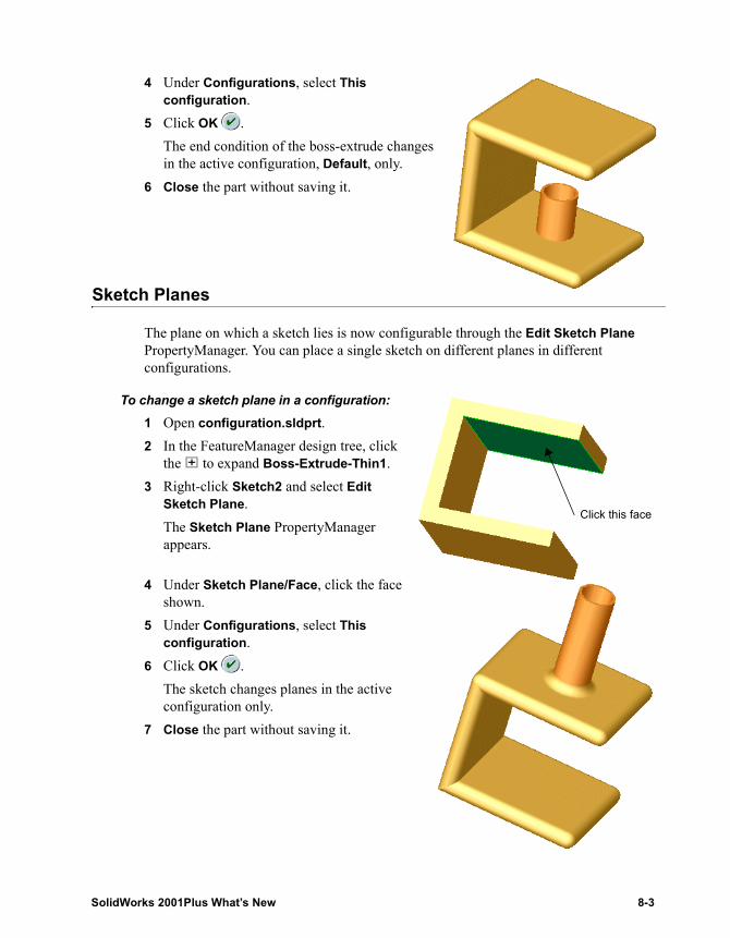
4 Under Configurations, select This configuration.
5 Click OK .The end condition of the boss-extrude changes in the active configuration, Default, only.
6 Close the part without saving it.
Sketch Planes
The plane on which a sketch lies is now configurable through the Edit Sketch Plane PropertyManager. You can place a single sketch on different planes in different configurations.
To change a sketch plane in a configuration:1 Open configuration.sldprt.2 In the FeatureManager design tree, click
the to expand Boss-Extrude-Thin1.3 Right-click Sketch2 and select Edit
Sketch Plane.The Sketch Plane PropertyManager appears.
4 Under Sketch Plane/Face, click the face shown.
5 Under Configurations, select This configuration.
6 Click OK .The sketch changes planes in the active configuration only.
7 Close the part without saving it.
Click this face
SolidWorks 2001Plus What’s New 8-3
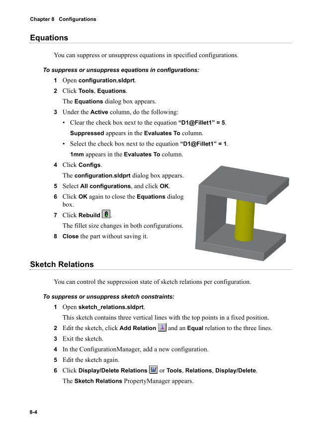
Chapter 8 Configurations
Equations
You can suppress or unsuppress equations in specified configurations.
To suppress or unsuppress equations in configurations:1 Open configuration.sldprt.2 Click Tools, Equations.
The Equations dialog box appears.3 Under the Active column, do the following:
• Clear the check box next to the equation “D1@Fillet1” = 5. Suppressed appears in the Evaluates To column.
• Select the check box next to the equation “D1@Fillet1” = 1.1mm appears in the Evaluates To column.
4 Click Configs.The configuration.sldprt dialog box appears.
5 Select All configurations, and click OK.6 Click OK again to close the Equations dialog
box.7 Click Rebuild .
The fillet size changes in both configurations.8 Close the part without saving it.
Sketch Relations
You can control the suppression state of sketch relations per configuration.
To suppress or unsuppress sketch constraints:1 Open sketch_relations.sldprt.
This sketch contains three vertical lines with the top points in a fixed position.2 Edit the sketch, click Add Relation and an Equal relation to the three lines.3 Exit the sketch.4 In the ConfigurationManager, add a new configuration.5 Edit the sketch again.6 Click Display/Delete Relations or Tools, Relations, Display/Delete.
The Sketch Relations PropertyManager appears.
8-4
7 Under Relations, do the following:• Select one of the Equal radius/length relations from the list.• Select the Suppressed check box.
The status changes to Driven.8 Under Configurations, do the following:
• Select Specify configurations.• Select Default.• Click to clear the configuration you added in step 4.
9 Click OK , but do not close the sketch.10 Drag the lines by the bottom end points to see how the Equal radius/length relation is
suppressed.
Sketch Dimensions
You can control the driving state of sketch dimensions in specified configurations to control the behavior of your model.
To control the driving state of sketch dimensions:1 Sketch and dimension a line.2 Right-click the dimension, and select Properties.
The Dimension Properties dialog box appears.3 Select the Driven check box.4 Click Specify Configs.
A dialog box appears.5 Select the configurations you want to apply the new settings to: This configuration,
All configurations, or Specify configurations.6 Click OK.7 Click OK again to close the Dimension Properties dialog box.
SolidWorks 2001Plus What’s New 8-5
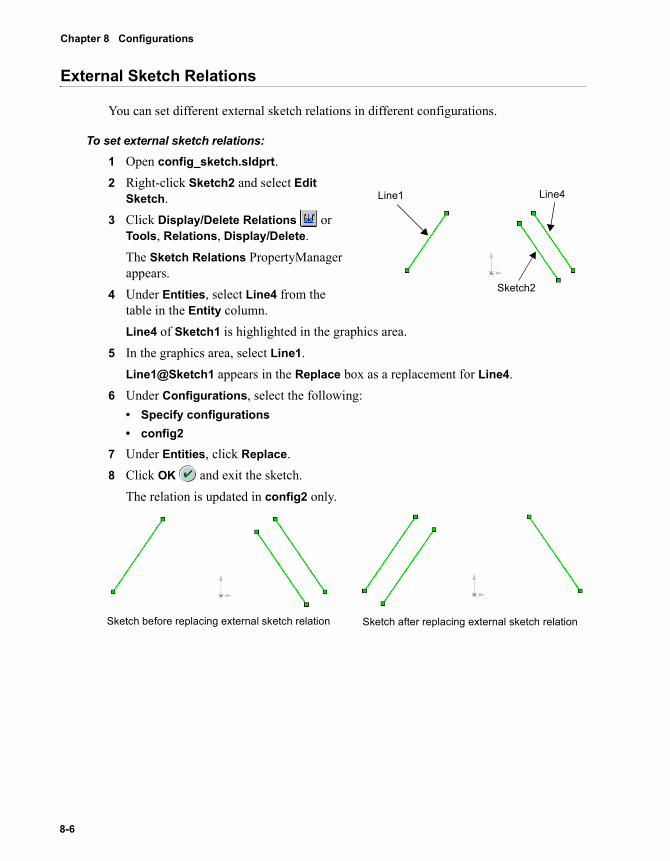
Chapter 8 Configurations
External Sketch Relations
You can set different external sketch relations in different configurations.
To set external sketch relations:1 Open config_sketch.sldprt.2 Right-click Sketch2 and select Edit
Sketch.3 Click Display/Delete Relations or
Tools, Relations, Display/Delete.The Sketch Relations PropertyManager appears.
4 Under Entities, select Line4 from the table in the Entity column.Line4 of Sketch1 is highlighted in the graphics area.
5 In the graphics area, select Line1.Line1@Sketch1 appears in the Replace box as a replacement for Line4.
6 Under Configurations, select the following:• Specify configurations• config2
7 Under Entities, click Replace.8 Click OK and exit the sketch.
The relation is updated in config2 only.
Line1 Line4
Sketch2
Sketch before replacing external sketch relation Sketch after replacing external sketch relation
8-6
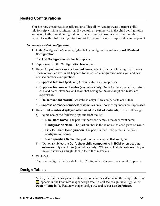
Nested Configurations
You can now create nested configurations. This allows you to create a parent-child relationship within a configuration. By default, all parameters in the child configuration are linked to the parent configuration. However, you can override any configurable parameter in the child configuration so that the parameter is no longer linked to the parent.
To create a nested configuration: 1 In the ConfigurationManager, right-click a configuration and select Add Derived
Configuration.The Add Configuration dialog box appears.
2 Type a name in the Configuration Name box.3 Under Properties for newly inserted items, select from the following check boxes.
These options control what happens to the nested configuration when you add new items to another configuration:• Suppress features (parts only). New features are suppressed.• Suppress features and mates (assemblies only). New features (including feature
cuts and holes, sketches, and so on that belong to the assembly) and mates are suppressed.
• Hide component models (assemblies only). New components are hidden.• Suppress component models (assemblies only). New components are suppressed.
4 Under Part number displayed when used in a bill of materials, do the following:a) Select one of the following options from the list:
• Document Name. The part number is the same as the document name.• Configuration Name. The part number is the same as the configuration name.• Link to Parent Configuration. The part number is the same as the parent
configuration name.• User Specified Name. The part number is a name that you type.
b) (Optional). Select the Don't show child components in BOM when used as sub-assembly check box (assemblies only). When checked, the sub-assembly is always shown as a single item in the bill of materials.
5 Click OK.The new configuration is added to the ConfigurationManager underneath its parent.
Design Tables
When you insert a design table into a part or assembly document, the design table icon appears in the FeatureManager design tree. To edit the design table, right-click
Design Table in the FeatureManager design tree and select Edit Definition.
SolidWorks 2001Plus What’s New 8-7
9 Drawings and Detailing
You can create 2D drawings from the 3D solid parts and assemblies you design. This chapter describes the enhancements to drawings in the following areas:
� Opening drawings from model documents
� Displaying drawing views in shaded mode
� New functionality in RapidDraft drawings
� Setting automatic hidden components list
� New tools to hide and show edges
� Displaying assembly explode lines in drawings
� Chinese (GB) detailing standard now available
� New functionality in dimensions
� New annotation tools
� Annotations now in the PropertyManager
SolidWorks 2001Plus What’s New 9-1
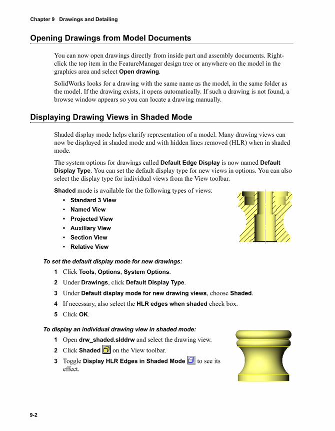
Chapter 9 Drawings and Detailing
Opening Drawings from Model Documents
You can now open drawings directly from inside part and assembly documents. Right-click the top item in the FeatureManager design tree or anywhere on the model in the graphics area and select Open drawing.
SolidWorks looks for a drawing with the same name as the model, in the same folder as the model. If the drawing exists, it opens automatically. If such a drawing is not found, a browse window appears so you can locate a drawing manually.
Displaying Drawing Views in Shaded Mode
Shaded display mode helps clarify representation of a model. Many drawing views can now be displayed in shaded mode and with hidden lines removed (HLR) when in shaded mode.
The system options for drawings called Default Edge Display is now named Default Display Type. You can set the default display type for new views in options. You can also select the display type for individual views from the View toolbar.
Shaded mode is available for the following types of views:• Standard 3 View• Named View• Projected View• Auxiliary View• Section View• Relative View
To set the default display mode for new drawings:1 Click Tools, Options, System Options.2 Under Drawings, click Default Display Type.3 Under Default display mode for new drawing views, choose Shaded. 4 If necessary, also select the HLR edges when shaded check box.5 Click OK.
To display an individual drawing view in shaded mode:1 Open drw_shaded.slddrw and select the drawing view.2 Click Shaded on the View toolbar.3 Toggle Display HLR Edges in Shaded Mode to see its
effect.
9-2
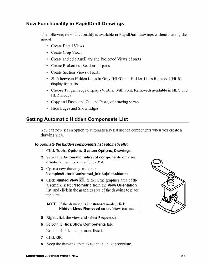
New Functionality in RapidDraft Drawings
The following new functionality is available in RapidDraft drawings without loading the model:
• Create Detail Views• Create Crop Views• Create and edit Auxiliary and Projected Views of parts• Create Broken-out Sections of parts• Create Section Views of parts• Shift between Hidden Lines in Gray (HLG) and Hidden Lines Removed (HLR)
display for parts• Choose Tangent edge display (Visible, With Font, Removed) available in HLG and
HLR modes• Copy and Paste, and Cut and Paste, of drawing views• Hide Edges and Show Edges
Setting Automatic Hidden Components List
You can now set an option to automatically list hidden components when you create a drawing view.
To populate the hidden components list automatically:1 Click Tools, Options, System Options, Drawings.2 Select the Automatic hiding of components on view
creation check box, then click OK.3 Open a new drawing and open
\samples\tutorial\universal_joint\ujoint.sldasm.4 Click Named View , click in the graphics area of the
assembly, select *Isometric from the View Orientation list, and click in the graphics area of the drawing to place the view.
5 Right-click the view and select Properties.6 Select the Hide/Show Components tab.
Note the hidden component listed.7 Click OK.8 Keep the drawing open to use in the next procedure.
NOTE: If the drawing is in Shaded mode, click Hidden Lines Removed on the View toolbar.
SolidWorks 2001Plus What’s New 9-3
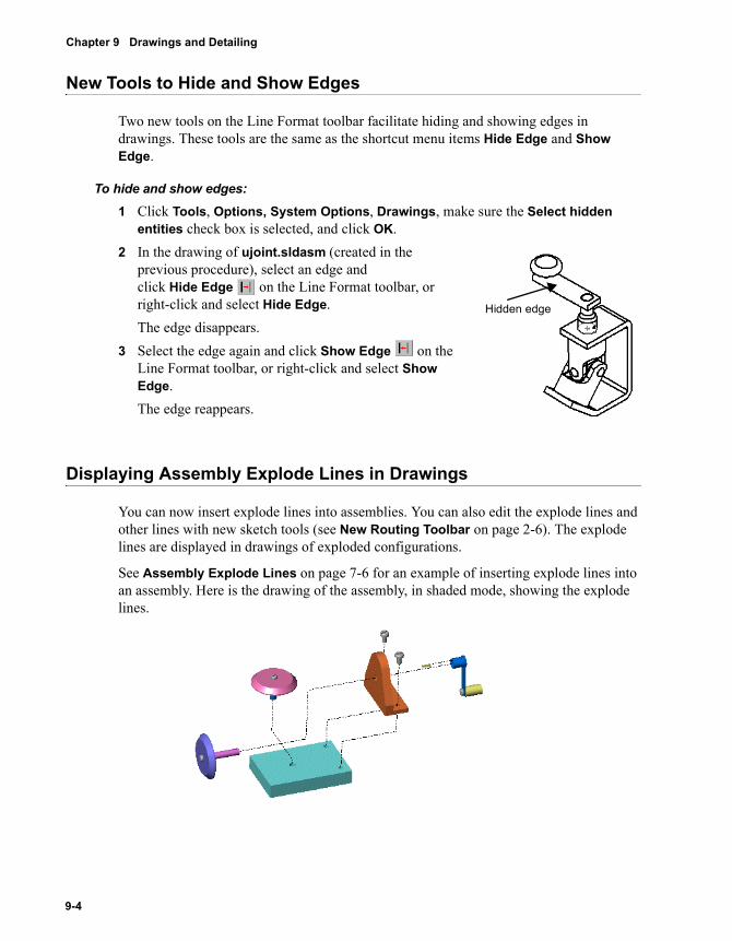
Chapter 9 Drawings and Detailing
New Tools to Hide and Show Edges
Two new tools on the Line Format toolbar facilitate hiding and showing edges in drawings. These tools are the same as the shortcut menu items Hide Edge and Show Edge.
To hide and show edges:1 Click Tools, Options, System Options, Drawings, make sure the Select hidden
entities check box is selected, and click OK.2 In the drawing of ujoint.sldasm (created in the
previous procedure), select an edge and click Hide Edge on the Line Format toolbar, or right-click and select Hide Edge.The edge disappears.
3 Select the edge again and click Show Edge on the Line Format toolbar, or right-click and select Show Edge.The edge reappears.
Displaying Assembly Explode Lines in Drawings
You can now insert explode lines into assemblies. You can also edit the explode lines and other lines with new sketch tools (see New Routing Toolbar on page 2-6). The explode lines are displayed in drawings of exploded configurations.
See Assembly Explode Lines on page 7-6 for an example of inserting explode lines into an assembly. Here is the drawing of the assembly, in shaded mode, showing the explode lines.
Hidden edge
9-4
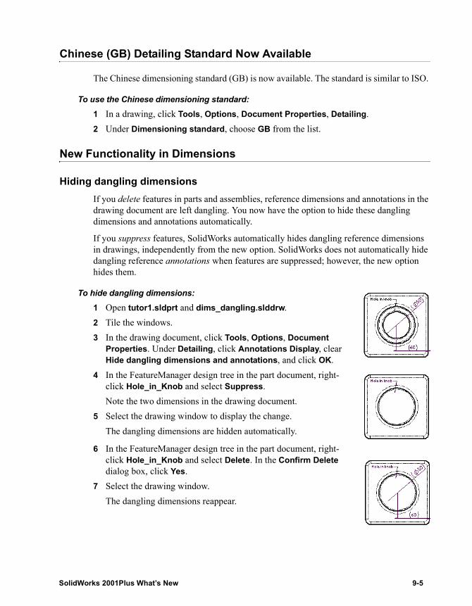
Chinese (GB) Detailing Standard Now Available
The Chinese dimensioning standard (GB) is now available. The standard is similar to ISO.
To use the Chinese dimensioning standard:1 In a drawing, click Tools, Options, Document Properties, Detailing.2 Under Dimensioning standard, choose GB from the list.
New Functionality in Dimensions
Hiding dangling dimensionsIf you delete features in parts and assemblies, reference dimensions and annotations in the drawing document are left dangling. You now have the option to hide these dangling dimensions and annotations automatically.
If you suppress features, SolidWorks automatically hides dangling reference dimensions in drawings, independently from the new option. SolidWorks does not automatically hide dangling reference annotations when features are suppressed; however, the new option hides them.
To hide dangling dimensions:1 Open tutor1.sldprt and dims_dangling.slddrw.2 Tile the windows.3 In the drawing document, click Tools, Options, Document
Properties. Under Detailing, click Annotations Display, clear Hide dangling dimensions and annotations, and click OK.
4 In the FeatureManager design tree in the part document, right-click Hole_in_Knob and select Suppress.Note the two dimensions in the drawing document.
5 Select the drawing window to display the change.The dangling dimensions are hidden automatically.
6 In the FeatureManager design tree in the part document, right-click Hole_in_Knob and select Delete. In the Confirm Delete dialog box, click Yes.
7 Select the drawing window.The dangling dimensions reappear.
SolidWorks 2001Plus What’s New 9-5
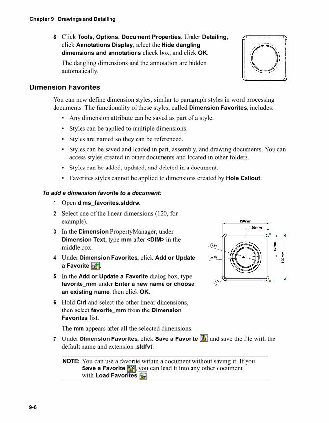
Chapter 9 Drawings and Detailing
8 Click Tools, Options, Document Properties. Under Detailing, click Annotations Display, select the Hide dangling dimensions and annotations check box, and click OK.The dangling dimensions and the annotation are hidden automatically.
Dimension FavoritesYou can now define dimension styles, similar to paragraph styles in word processing documents. The functionality of these styles, called Dimension Favorites, includes:
• Any dimension attribute can be saved as part of a style.• Styles can be applied to multiple dimensions.• Styles are named so they can be referenced.• Styles can be saved and loaded in part, assembly, and drawing documents. You can
access styles created in other documents and located in other folders.• Styles can be added, updated, and deleted in a document.• Favorites styles cannot be applied to dimensions created by Hole Callout.
To add a dimension favorite to a document:1 Open dims_favorites.slddrw.2 Select one of the linear dimensions (120, for
example).3 In the Dimension PropertyManager, under
Dimension Text, type mm after <DIM> in the middle box.
4 Under Dimension Favorites, click Add or Update a Favorite .
5 In the Add or Update a Favorite dialog box, type favorite_mm under Enter a new name or choose an existing name, then click OK.
6 Hold Ctrl and select the other linear dimensions, then select favorite_mm from the Dimension Favorites list. The mm appears after all the selected dimensions.
7 Under Dimension Favorites, click Save a Favorite and save the file with the default name and extension .sldfvt.
NOTE: You can use a favorite within a document without saving it. If you Save a Favorite , you can load it into any other document with Load Favorites .
9-6
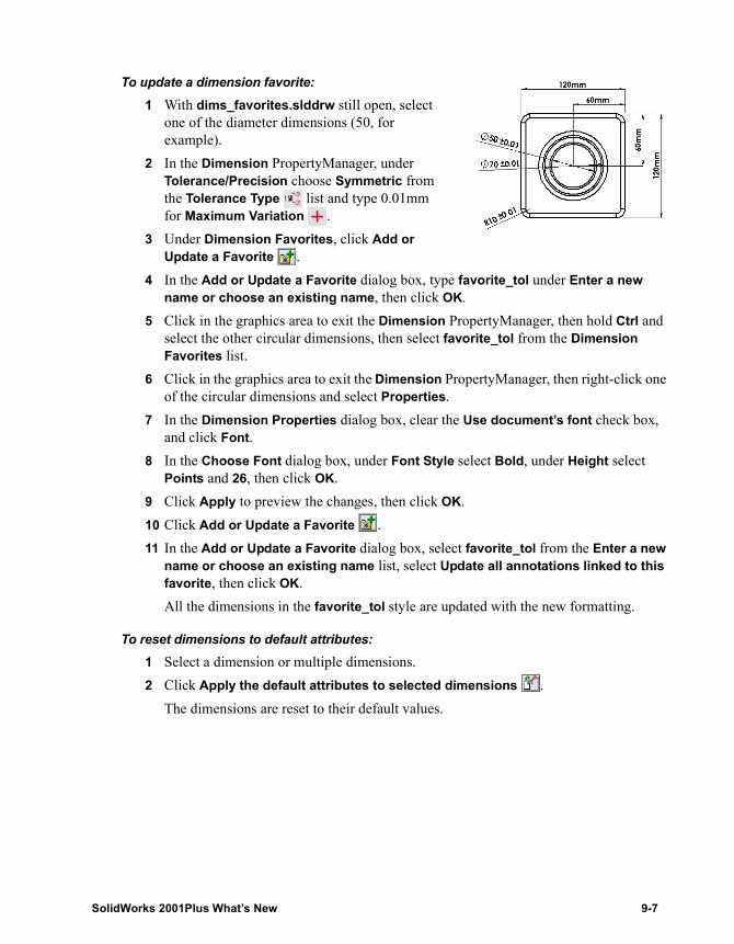
To update a dimension favorite:1 With dims_favorites.slddrw still open, select
one of the diameter dimensions (50, for example).
2 In the Dimension PropertyManager, under Tolerance/Precision choose Symmetric from the Tolerance Type list and type 0.01mm for Maximum Variation .
3 Under Dimension Favorites, click Add or Update a Favorite .
4 In the Add or Update a Favorite dialog box, type favorite_tol under Enter a new name or choose an existing name, then click OK.
5 Click in the graphics area to exit the Dimension PropertyManager, then hold Ctrl and select the other circular dimensions, then select favorite_tol from the Dimension Favorites list.
6 Click in the graphics area to exit the Dimension PropertyManager, then right-click one of the circular dimensions and select Properties.
7 In the Dimension Properties dialog box, clear the Use document’s font check box, and click Font.
8 In the Choose Font dialog box, under Font Style select Bold, under Height select Points and 26, then click OK.
9 Click Apply to preview the changes, then click OK.10 Click Add or Update a Favorite .11 In the Add or Update a Favorite dialog box, select favorite_tol from the Enter a new
name or choose an existing name list, select Update all annotations linked to this favorite, then click OK.All the dimensions in the favorite_tol style are updated with the new formatting.
To reset dimensions to default attributes:1 Select a dimension or multiple dimensions.2 Click Apply the default attributes to selected dimensions .
The dimensions are reset to their default values.
SolidWorks 2001Plus What’s New 9-7
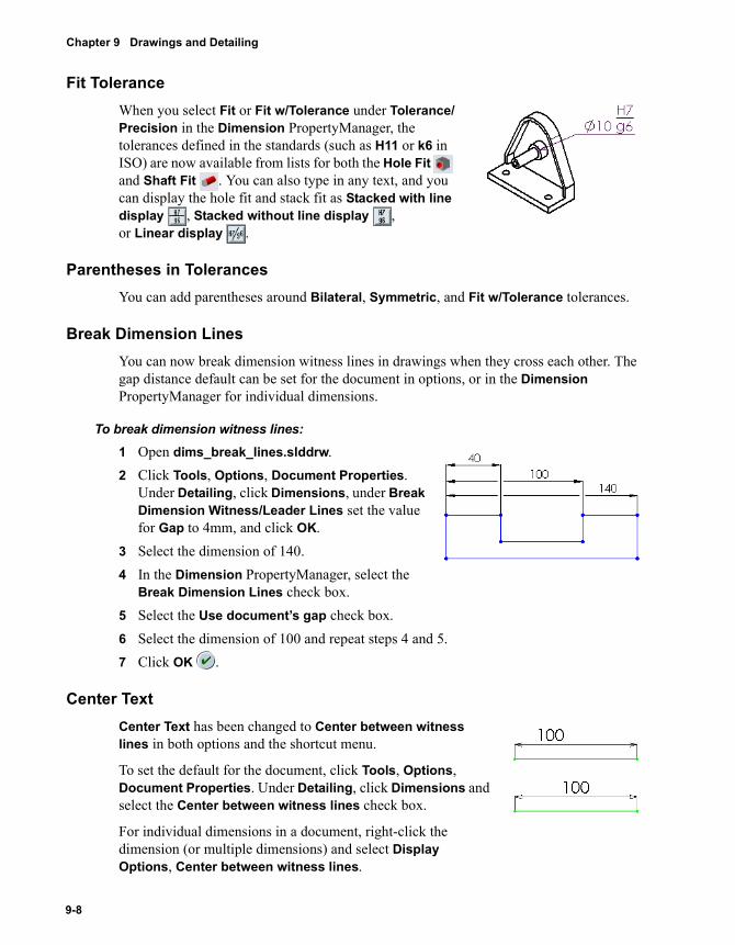
Chapter 9 Drawings and Detailing
Fit ToleranceWhen you select Fit or Fit w/Tolerance under Tolerance/Precision in the Dimension PropertyManager, the tolerances defined in the standards (such as H11 or k6 in ISO) are now available from lists for both the Hole Fit and Shaft Fit . You can also type in any text, and you can display the hole fit and stack fit as Stacked with line display , Stacked without line display , or Linear display .
Parentheses in TolerancesYou can add parentheses around Bilateral, Symmetric, and Fit w/Tolerance tolerances.
Break Dimension LinesYou can now break dimension witness lines in drawings when they cross each other. The gap distance default can be set for the document in options, or in the Dimension PropertyManager for individual dimensions.
To break dimension witness lines:1 Open dims_break_lines.slddrw.2 Click Tools, Options, Document Properties.
Under Detailing, click Dimensions, under Break Dimension Witness/Leader Lines set the value for Gap to 4mm, and click OK.
3 Select the dimension of 140.4 In the Dimension PropertyManager, select the
Break Dimension Lines check box.5 Select the Use document’s gap check box.6 Select the dimension of 100 and repeat steps 4 and 5.7 Click OK .
Center Text Center Text has been changed to Center between witness lines in both options and the shortcut menu.
To set the default for the document, click Tools, Options, Document Properties. Under Detailing, click Dimensions and select the Center between witness lines check box.
For individual dimensions in a document, right-click the dimension (or multiple dimensions) and select Display Options, Center between witness lines.
9-8
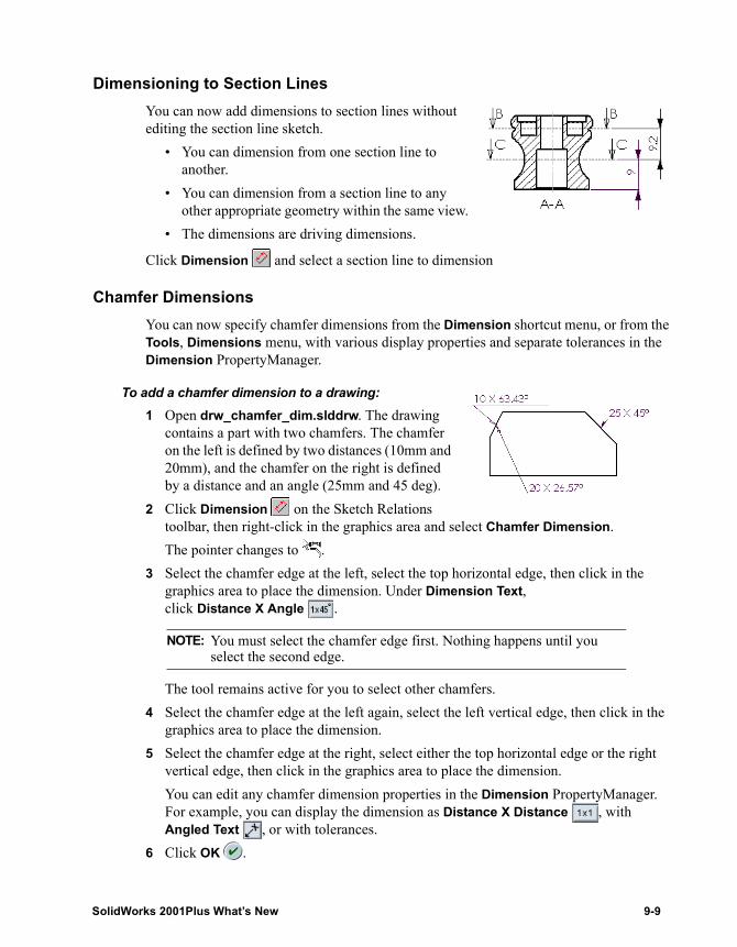
Dimensioning to Section LinesYou can now add dimensions to section lines without editing the section line sketch.
• You can dimension from one section line to another.
• You can dimension from a section line to any other appropriate geometry within the same view.
• The dimensions are driving dimensions.
Click Dimension and select a section line to dimension
Chamfer DimensionsYou can now specify chamfer dimensions from the Dimension shortcut menu, or from the Tools, Dimensions menu, with various display properties and separate tolerances in the Dimension PropertyManager.
To add a chamfer dimension to a drawing:1 Open drw_chamfer_dim.slddrw. The drawing
contains a part with two chamfers. The chamfer on the left is defined by two distances (10mm and 20mm), and the chamfer on the right is defined by a distance and an angle (25mm and 45 deg).
2 Click Dimension on the Sketch Relations toolbar, then right-click in the graphics area and select Chamfer Dimension.The pointer changes to .
3 Select the chamfer edge at the left, select the top horizontal edge, then click in the graphics area to place the dimension. Under Dimension Text, click Distance X Angle .
The tool remains active for you to select other chamfers.4 Select the chamfer edge at the left again, select the left vertical edge, then click in the
graphics area to place the dimension.5 Select the chamfer edge at the right, select either the top horizontal edge or the right
vertical edge, then click in the graphics area to place the dimension.You can edit any chamfer dimension properties in the Dimension PropertyManager. For example, you can display the dimension as Distance X Distance , with Angled Text , or with tolerances.
6 Click OK .
NOTE: You must select the chamfer edge first. Nothing happens until you select the second edge.
SolidWorks 2001Plus What’s New 9-9
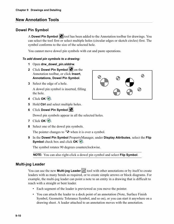
Chapter 9 Drawings and Detailing
New Annotation Tools
Dowel Pin SymbolA Dowel Pin Symbol tool has been added to the Annotation toolbar for drawings. You can select the tool first or select multiple holes (circular edges or sketch circles) first. The symbol conforms to the size of the selected hole.
You cannot move dowel pin symbols with cut and paste operations.
To add dowel pin symbols to a drawing:1 Open drw_dowel_pin.slddrw.2 Click Dowel Pin Symbol on the
Annotation toolbar, or click Insert, Annotations, Dowel Pin Symbol.
3 Select the edge of a hole.A dowel pin symbol is inserted, filling the hole.
4 Click OK .5 Hold Ctrl and select multiple holes.6 Click Dowel Pin Symbol .
Dowel pin symbols appear in all the selected holes.7 Click OK .8 Select one of the dowel pin symbols.
The pointer changes to when it is over a symbol.9 In the Dowel Pin Symbol PropertyManager, under Display Attributes, select the Flip
Symbol check box and click OK .The symbol rotates 90 degrees counterclockwise.
Multi-jog LeaderYou can use the new Multi-jog Leader tool with other annotations or by itself to create leaders with as many bends as required, or to create simple arrows or block diagrams. For example, the multi-jog leader can point a note to an entity in a drawing that is difficult to reach with a straight or bent leader.
• Each segment of the leader is previewed as you move the pointer.• You can attach the leader to a dock point of an annotation (Note, Surface Finish
Symbol, Geometric Tolerance Symbol, and so on), or you can start it anywhere on a drawing sheet. A leader attached to an annotation moves with the annotation.
NOTE: You can also right-click a dowel pin symbol and select Flip Symbol.
9-10
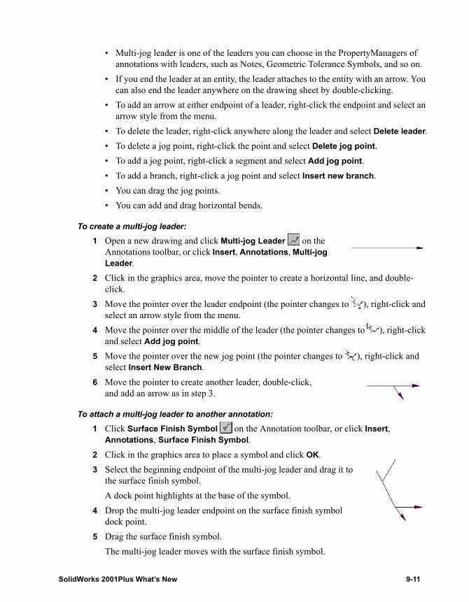
• Multi-jog leader is one of the leaders you can choose in the PropertyManagers of annotations with leaders, such as Notes, Geometric Tolerance Symbols, and so on.
• If you end the leader at an entity, the leader attaches to the entity with an arrow. You can also end the leader anywhere on the drawing sheet by double-clicking.
• To add an arrow at either endpoint of a leader, right-click the endpoint and select an arrow style from the menu.
• To delete the leader, right-click anywhere along the leader and select Delete leader.• To delete a jog point, right-click the point and select Delete jog point.• To add a jog point, right-click a segment and select Add jog point.• To add a branch, right-click a jog point and select Insert new branch.• You can drag the jog points.• You can add and drag horizontal bends.
To create a multi-jog leader:1 Open a new drawing and click Multi-jog Leader on the
Annotations toolbar, or click Insert, Annotations, Multi-jog Leader.
2 Click in the graphics area, move the pointer to create a horizontal line, and double-click.
3 Move the pointer over the leader endpoint (the pointer changes to ), right-click and select an arrow style from the menu.
4 Move the pointer over the middle of the leader (the pointer changes to ), right-click and select Add jog point.
5 Move the pointer over the new jog point (the pointer changes to ), right-click and select Insert New Branch.
6 Move the pointer to create another leader, double-click, and add an arrow as in step 3.
To attach a multi-jog leader to another annotation:1 Click Surface Finish Symbol on the Annotation toolbar, or click Insert,
Annotations, Surface Finish Symbol.2 Click in the graphics area to place a symbol and click OK.3 Select the beginning endpoint of the multi-jog leader and drag it to
the surface finish symbol.A dock point highlights at the base of the symbol.
4 Drop the multi-jog leader endpoint on the surface finish symbol dock point.
5 Drag the surface finish symbol.The multi-jog leader moves with the surface finish symbol.
SolidWorks 2001Plus What’s New 9-11
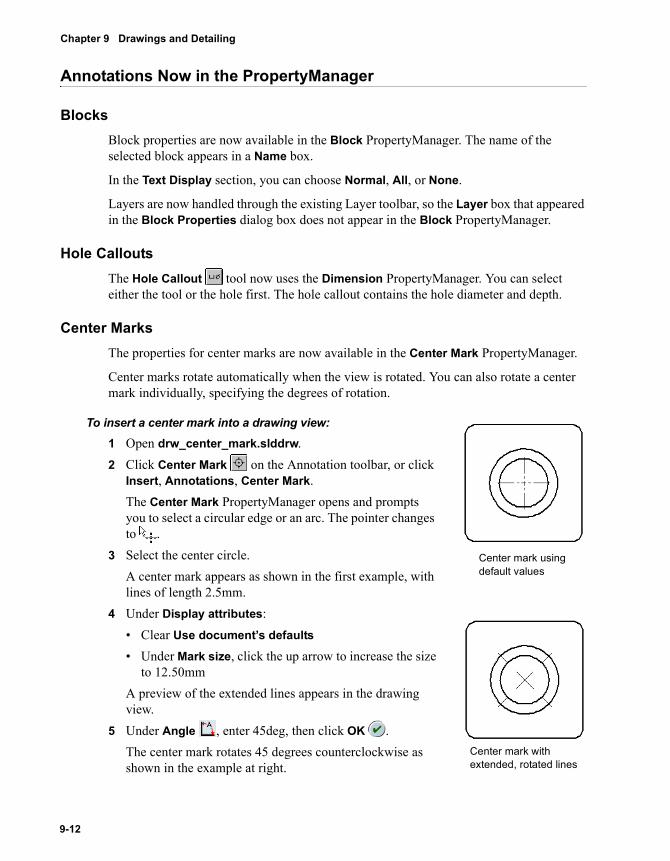
Chapter 9 Drawings and Detailing
Annotations Now in the PropertyManager
BlocksBlock properties are now available in the Block PropertyManager. The name of the selected block appears in a Name box.
In the Text Display section, you can choose Normal, All, or None.
Layers are now handled through the existing Layer toolbar, so the Layer box that appeared in the Block Properties dialog box does not appear in the Block PropertyManager.
Hole CalloutsThe Hole Callout tool now uses the Dimension PropertyManager. You can select either the tool or the hole first. The hole callout contains the hole diameter and depth.
Center MarksThe properties for center marks are now available in the Center Mark PropertyManager.
Center marks rotate automatically when the view is rotated. You can also rotate a center mark individually, specifying the degrees of rotation.
To insert a center mark into a drawing view:1 Open drw_center_mark.slddrw.2 Click Center Mark on the Annotation toolbar, or click
Insert, Annotations, Center Mark.The Center Mark PropertyManager opens and prompts you to select a circular edge or an arc. The pointer changes to .
3 Select the center circle.A center mark appears as shown in the first example, with lines of length 2.5mm.
4 Under Display attributes:• Clear Use document’s defaults• Under Mark size, click the up arrow to increase the size
to 12.50mmA preview of the extended lines appears in the drawing view.
5 Under Angle , enter 45deg, then click OK .The center mark rotates 45 degrees counterclockwise as shown in the example at right.
Center mark using default values
Center mark with extended, rotated lines
9-12
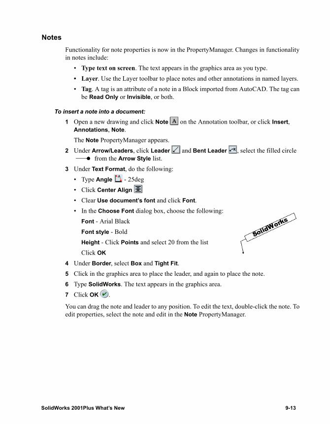
NotesFunctionality for note properties is now in the PropertyManager. Changes in functionality in notes include:
• Type text on screen. The text appears in the graphics area as you type.• Layer. Use the Layer toolbar to place notes and other annotations in named layers.• Tag. A tag is an attribute of a note in a Block imported from AutoCAD. The tag can
be Read Only or Invisible, or both.
To insert a note into a document:1 Open a new drawing and click Note on the Annotation toolbar, or click Insert,
Annotations, Note.The Note PropertyManager appears.
2 Under Arrow/Leaders, click Leader and Bent Leader , select the filled circle from the Arrow Style list.
3 Under Text Format, do the following:• Type Angle - 25deg• Click Center Align
• Clear Use document’s font and click Font.• In the Choose Font dialog box, choose the following:
Font - Arial BlackFont style - BoldHeight - Click Points and select 20 from the listClick OK
4 Under Border, select Box and Tight Fit.5 Click in the graphics area to place the leader, and again to place the note.6 Type SolidWorks. The text appears in the graphics area.7 Click OK .
You can drag the note and leader to any position. To edit the text, double-click the note. To edit properties, select the note and edit in the Note PropertyManager.
SolidWorks 2001Plus What’s New 9-13

10 Import and Export
This chapter describes the enhancements to Import and Export items, including:
� General information
� DXF/DWG files
� STEP files
SolidWorks 2001Plus What’s New 10-1
Chapter 10 Import and Export
General Information
Import Diagnosis and Improve GeometryThe Import Diagnosis dialog box and the Improve Geometry menu item have been moved to a new Import Diagnosis PropertyManager. The functionality of these items has not changed.
To open the Import Diagnosis PropertyManager, right-click an imported feature in the FeatureManager design tree, and select Diagnosis. The gap and face check results appear under Gaps and Faces.
To improve and rebuild the feature geometry, click Improve Geometry. Results are still reported in the Improve Geometry dialog box.
Import OptionsThere are two new import options to help you properly import data:
• Perform full entity check and repair errors• Customize tolerance
Entity Check and Repair
For ACIS®, IGES, STEP, and VDAFS files, you now have the option to perform a full entity check and repair errors (default is enabled). With this option enabled, import performance is slower because the software spends more time checking and repairing the model entities. If the quality of the imported data is good, you may not have to enable this option.
To set the entity check and repair option:1 Click File, Open.2 Set Files of type to either ACIS, IGES, STEP, or VDAFS, then click Options.
The Import Options dialog box appears. Note that the new option, Perform full entity check and repair errors, is enabled.
3 Click OK.4 Browse to the file to import and click Open to perform the check.
10-2
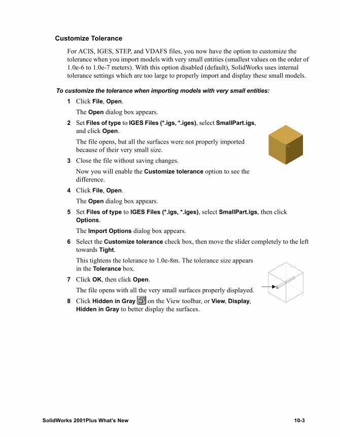
Customize Tolerance
For ACIS, IGES, STEP, and VDAFS files, you now have the option to customize the tolerance when you import models with very small entities (smallest values on the order of 1.0e-6 to 1.0e-7 meters). With this option disabled (default), SolidWorks uses internal tolerance settings which are too large to properly import and display these small models.
To customize the tolerance when importing models with very small entities:1 Click File, Open.
The Open dialog box appears.2 Set Files of type to IGES Files (*.igs, *.iges), select SmallPart.igs,
and click Open. The file opens, but all the surfaces were not properly imported because of their very small size.
3 Close the file without saving changes.Now you will enable the Customize tolerance option to see the difference.
4 Click File, Open.
The Open dialog box appears.5 Set Files of type to IGES Files (*.igs, *.iges), select SmallPart.igs, then click
Options.The Import Options dialog box appears.
6 Select the Customize tolerance check box, then move the slider completely to the left towards Tight.This tightens the tolerance to 1.0e-8m. The tolerance size appears in the Tolerance box.
7 Click OK, then click Open.The file opens with all the very small surfaces properly displayed.
8 Click Hidden in Gray on the View toolbar, or View, Display, Hidden in Gray to better display the surfaces.
SolidWorks 2001Plus What’s New 10-3
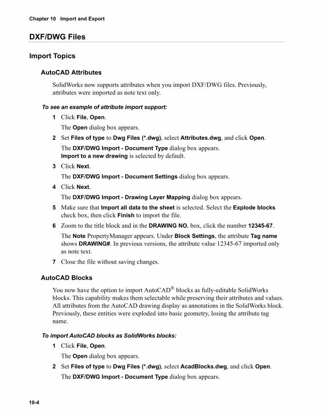
Chapter 10 Import and Export
DXF/DWG Files
Import Topics
AutoCAD Attributes
SolidWorks now supports attributes when you import DXF/DWG files. Previously, attributes were imported as note text only.
To see an example of attribute import support:1 Click File, Open.
The Open dialog box appears.2 Set Files of type to Dwg Files (*.dwg), select Attributes.dwg, and click Open.
The DXF/DWG Import - Document Type dialog box appears. Import to a new drawing is selected by default.
3 Click Next.The DXF/DWG Import - Document Settings dialog box appears.
4 Click Next.The DXF/DWG Import - Drawing Layer Mapping dialog box appears.
5 Make sure that Import all data to the sheet is selected. Select the Explode blocks check box, then click Finish to import the file.
6 Zoom to the title block and in the DRAWING NO. box, click the number 12345-67.The Note PropertyManager appears. Under Block Settings, the attribute Tag name shows DRAWING#. In previous versions, the attribute value 12345-67 imported only as note text.
7 Close the file without saving changes.
AutoCAD Blocks
You now have the option to import AutoCAD® blocks as fully-editable SolidWorks blocks. This capability makes them selectable while preserving their attributes and values. All attributes from the AutoCAD drawing display as annotations in the SolidWorks block. Previously, these entities were exploded into basic geometry, losing the attribute tag name.
To import AutoCAD blocks as SolidWorks blocks:1 Click File, Open.
The Open dialog box appears.2 Set Files of type to Dwg Files (*.dwg), select AcadBlocks.dwg, and click Open.
The DXF/DWG Import - Document Type dialog box appears.
10-4
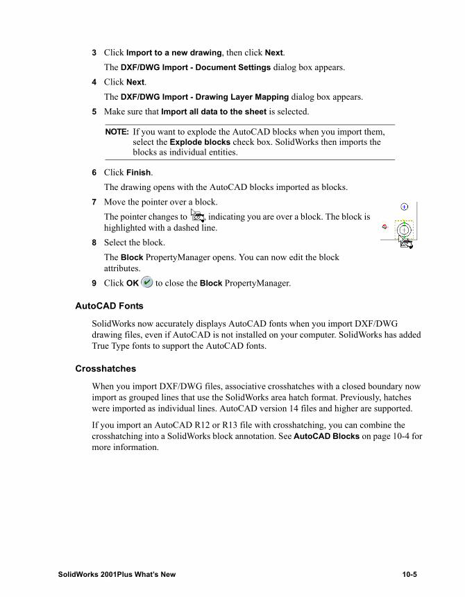
3 Click Import to a new drawing, then click Next.The DXF/DWG Import - Document Settings dialog box appears.
4 Click Next.The DXF/DWG Import - Drawing Layer Mapping dialog box appears.
5 Make sure that Import all data to the sheet is selected.
6 Click Finish.The drawing opens with the AutoCAD blocks imported as blocks.
7 Move the pointer over a block. The pointer changes to , indicating you are over a block. The block is highlighted with a dashed line.
8 Select the block.The Block PropertyManager opens. You can now edit the block attributes.
9 Click OK to close the Block PropertyManager.
AutoCAD Fonts
SolidWorks now accurately displays AutoCAD fonts when you import DXF/DWG drawing files, even if AutoCAD is not installed on your computer. SolidWorks has added True Type fonts to support the AutoCAD fonts.
Crosshatches
When you import DXF/DWG files, associative crosshatches with a closed boundary now import as grouped lines that use the SolidWorks area hatch format. Previously, hatches were imported as individual lines. AutoCAD version 14 files and higher are supported.
If you import an AutoCAD R12 or R13 file with crosshatching, you can combine the crosshatching into a SolidWorks block annotation. See AutoCAD Blocks on page 10-4 for more information.
NOTE: If you want to explode the AutoCAD blocks when you import them, select the Explode blocks check box. SolidWorks then imports the blocks as individual entities.
SolidWorks 2001Plus What’s New 10-5
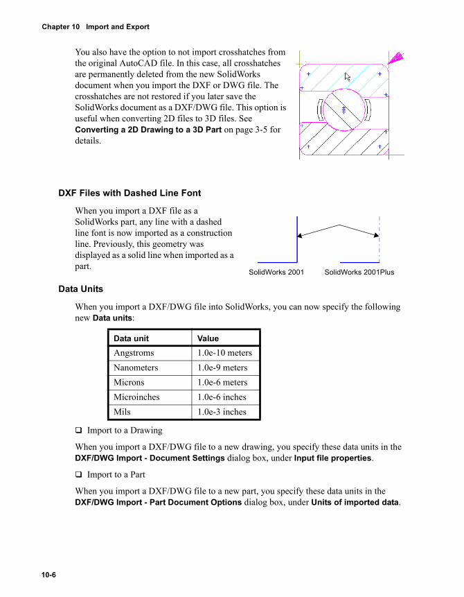
Chapter 10 Import and Export
You also have the option to not import crosshatches from the original AutoCAD file. In this case, all crosshatches are permanently deleted from the new SolidWorks document when you import the DXF or DWG file. The crosshatches are not restored if you later save the SolidWorks document as a DXF/DWG file. This option is useful when converting 2D files to 3D files. See Converting a 2D Drawing to a 3D Part on page 3-5 for details.
DXF Files with Dashed Line Font
When you import a DXF file as a SolidWorks part, any line with a dashed line font is now imported as a construction line. Previously, this geometry was displayed as a solid line when imported as a part.
Data Units
When you import a DXF/DWG file into SolidWorks, you can now specify the following new Data units:
� Import to a Drawing
When you import a DXF/DWG file to a new drawing, you specify these data units in the DXF/DWG Import - Document Settings dialog box, under Input file properties.
� Import to a Part
When you import a DXF/DWG file to a new part, you specify these data units in the DXF/DWG Import - Part Document Options dialog box, under Units of imported data.
Data unit ValueAngstroms 1.0e-10 metersNanometers 1.0e-9 metersMicrons 1.0e-6 metersMicroinches 1.0e-6 inchesMils 1.0e-3 inches
SolidWorks 2001 SolidWorks 2001Plus
10-6
Export Topics
Export Option 1:1
You now have the option to export a SolidWorks drawing document using a model geometry scale of 1:1. The paper or sheet scale is not normally used when you enable this option.
Previously, SolidWorks software always exported the DXF/DWG file based on the sheet scale. The drawing border was the correct size and items dimensioned correctly, but the actual geometry line length was at the sheet scale, and could not be used with CAM software.
To export a SolidWorks drawing document as a DXF/DWG file with a 1:1 model geometry scale:1 Open ExportScale.slddrw.2 Click File, Save As.
The Save As dialog box appears.3 Set Save as type to Dwg Files (*.dwg) or Dxf Files (*.dxf), then click Options.
The DXF/DWG Export Options dialog box appears.4 Select the 1:1 Scale output check box.
The Base scale box is activated and displays view scale = 1/2: count = 2. Base scale refers to the basis used for the 1:1 scale output of the geometry, based on the various drawing view scales on the sheet. If you have a view selected, the view scale and count values for this selected view appear in the Base scale box. If no view is selected, the view scale with the highest count is displayed by default.
5 Display the base scale menu items:• sheet scale = 1/2: count = 1• view scale = 1/3: count = 1• view scale = 1/2: count = 2• view scale = 1/1: count = 1The menu displays the sheet scale and view scales. There can be multiple view scales on a sheet. Count indicates the number of occurrences of this scale in the drawing document.
6 Make sure the Custom Map SolidWorks to DXF check box is cleared, then click OK.7 Click Save in the Save As dialog box.
The drawing document is saved with a model geometry scale of 1:1 for the chosen views, with the remainder of the sheet scaled accordingly.
SolidWorks 2001Plus What’s New 10-7

Chapter 10 Import and Export
AutoCAD Line Fonts
When you export SolidWorks drawing documents to DXF/DWG files, you now have the option to map SolidWorks line fonts to the original AutoCAD stock line types. Line font thickness is mapped to the closest AutoCAD line weight value.
To export a SolidWorks drawing document as a DXF/DWG file using AutoCAD line types:1 With a SolidWorks drawing document open, click File, Save As.
The Save As dialog box appears.2 Set Save as type to Dwg Files (*.dwg) or Dxf Files (*.dxf), then click Options.
The DXF/DWG Export Options dialog box appears.3 Select AutoCAD Standard Styles from the Line styles box.4 Click OK, then click Save in the Save As dialog box.5 If a message box appears about scaling and dimensions, click OK.
The drawing document is saved using AutoCAD line types.
NOTE: AutoCAD line weight value mapping is only supported for AutoCAD Version setting R2000 and higher in the DXF/DWG Export Options dialog box.
10-8
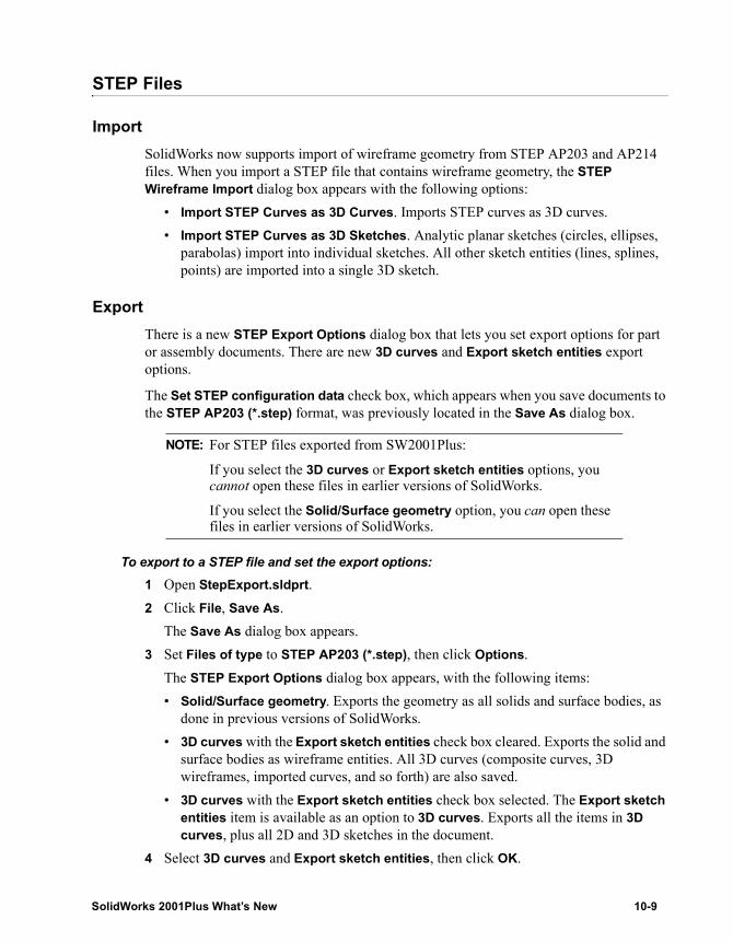
STEP Files
ImportSolidWorks now supports import of wireframe geometry from STEP AP203 and AP214 files. When you import a STEP file that contains wireframe geometry, the STEP Wireframe Import dialog box appears with the following options:
• Import STEP Curves as 3D Curves. Imports STEP curves as 3D curves.• Import STEP Curves as 3D Sketches. Analytic planar sketches (circles, ellipses,
parabolas) import into individual sketches. All other sketch entities (lines, splines, points) are imported into a single 3D sketch.
ExportThere is a new STEP Export Options dialog box that lets you set export options for part or assembly documents. There are new 3D curves and Export sketch entities export options.
The Set STEP configuration data check box, which appears when you save documents to the STEP AP203 (*.step) format, was previously located in the Save As dialog box.
To export to a STEP file and set the export options:1 Open StepExport.sldprt.2 Click File, Save As.
The Save As dialog box appears.3 Set Files of type to STEP AP203 (*.step), then click Options.
The STEP Export Options dialog box appears, with the following items:• Solid/Surface geometry. Exports the geometry as all solids and surface bodies, as
done in previous versions of SolidWorks.• 3D curves with the Export sketch entities check box cleared. Exports the solid and
surface bodies as wireframe entities. All 3D curves (composite curves, 3D wireframes, imported curves, and so forth) are also saved.
• 3D curves with the Export sketch entities check box selected. The Export sketch entities item is available as an option to 3D curves. Exports all the items in 3D curves, plus all 2D and 3D sketches in the document.
4 Select 3D curves and Export sketch entities, then click OK.
NOTE: For STEP files exported from SW2001Plus:
If you select the 3D curves or Export sketch entities options, you cannot open these files in earlier versions of SolidWorks.
If you select the Solid/Surface geometry option, you can open these files in earlier versions of SolidWorks.
SolidWorks 2001Plus What’s New 10-9
Chapter 10 Import and Export
5 Click Save and save the file as StepExport.STEP.Because you selected the 3D Curves option:• All edges of the solid and surface bodies are exported as wireframe entities. • All 3D curves in the part are exported. • No surface or solid from the model is exported.Because you selected the Export sketch entities option, in addition to the above, all 2D and 3D sketches are also exported.
6 Open StepExport.STEP to view the results.The STEP Wireframe Import dialog box appears.• If you select Import STEP Curves as 3D Curves, all 3D curves are imported as 3D
curves.• If you select Import STEP Curves as 3D Sketches, all 3D curves are imported as
3D sketches. Additionally, all lines and splines are imported into a single 3D sketch.Because you cannot group the sketch elements together in a STEP file, when you open the file in SolidWorks, circles, ellipses, and parabolas are imported into individual 2D sketches.
10-10
11 Sheet Metal
This chapter describes enhancements to the SolidWorks sheet metal functionality including:
� New sheet metal features such as:• Hem• Jog• Break Corner
� Improved sheet metal features such as:• Corner Treatments• Partial Miter Flange• Open Loop Miter Flange
SolidWorks 2001Plus What’s New 11-1
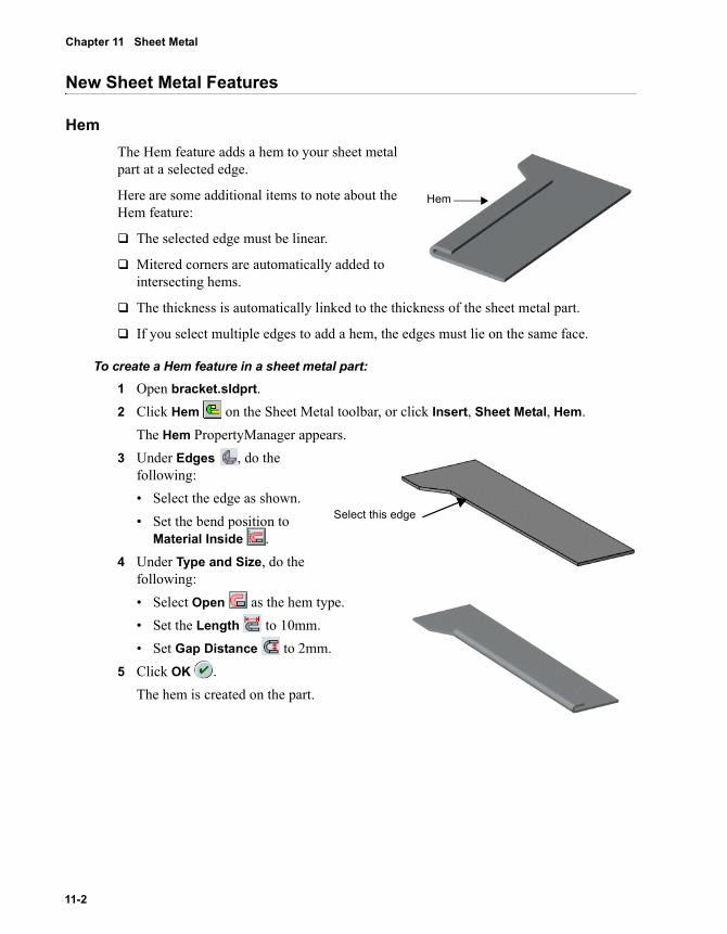
Chapter 11 Sheet Metal
New Sheet Metal Features
HemThe Hem feature adds a hem to your sheet metal part at a selected edge.
Here are some additional items to note about the Hem feature:
� The selected edge must be linear.
� Mitered corners are automatically added to intersecting hems.
� The thickness is automatically linked to the thickness of the sheet metal part.
� If you select multiple edges to add a hem, the edges must lie on the same face.
To create a Hem feature in a sheet metal part:1 Open bracket.sldprt.2 Click Hem on the Sheet Metal toolbar, or click Insert, Sheet Metal, Hem.
The Hem PropertyManager appears.3 Under Edges , do the
following:• Select the edge as shown.• Set the bend position to
Material Inside .4 Under Type and Size, do the
following:• Select Open as the hem type.• Set the Length to 10mm.• Set Gap Distance to 2mm.
5 Click OK .The hem is created on the part.
Hem
Select this edge
11-2
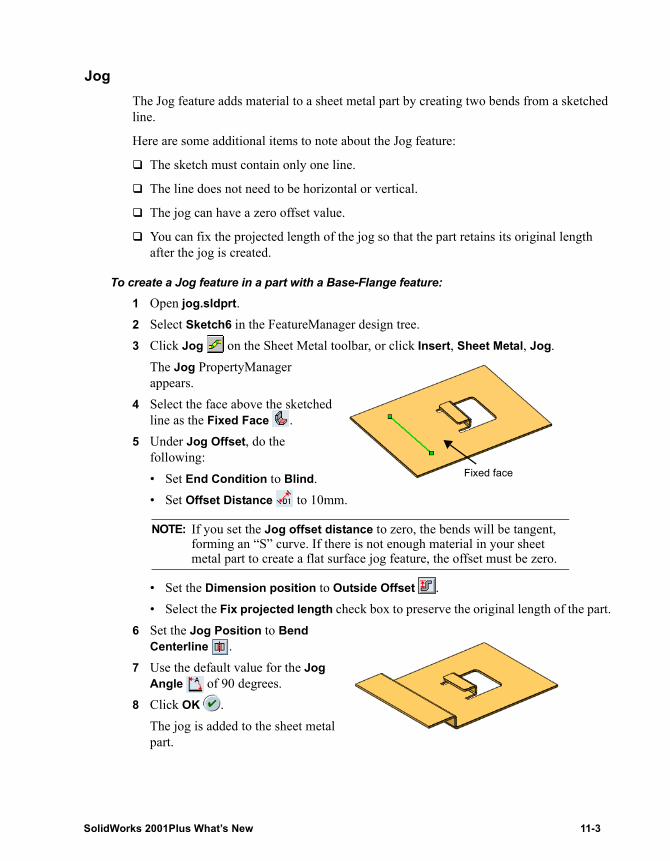
JogThe Jog feature adds material to a sheet metal part by creating two bends from a sketched line.
Here are some additional items to note about the Jog feature:
� The sketch must contain only one line.
� The line does not need to be horizontal or vertical.
� The jog can have a zero offset value.
� You can fix the projected length of the jog so that the part retains its original length after the jog is created.
To create a Jog feature in a part with a Base-Flange feature:1 Open jog.sldprt.2 Select Sketch6 in the FeatureManager design tree.3 Click Jog on the Sheet Metal toolbar, or click Insert, Sheet Metal, Jog.
The Jog PropertyManager appears.
4 Select the face above the sketched line as the Fixed Face .
5 Under Jog Offset, do the following:• Set End Condition to Blind.• Set Offset Distance to 10mm.
• Set the Dimension position to Outside Offset .• Select the Fix projected length check box to preserve the original length of the part.
6 Set the Jog Position to Bend Centerline .
7 Use the default value for the Jog Angle of 90 degrees.
8 Click OK .The jog is added to the sheet metal part.
NOTE: If you set the Jog offset distance to zero, the bends will be tangent, forming an “S” curve. If there is not enough material in your sheet metal part to create a flat surface jog feature, the offset must be zero.
Fixed face
SolidWorks 2001Plus What’s New 11-3
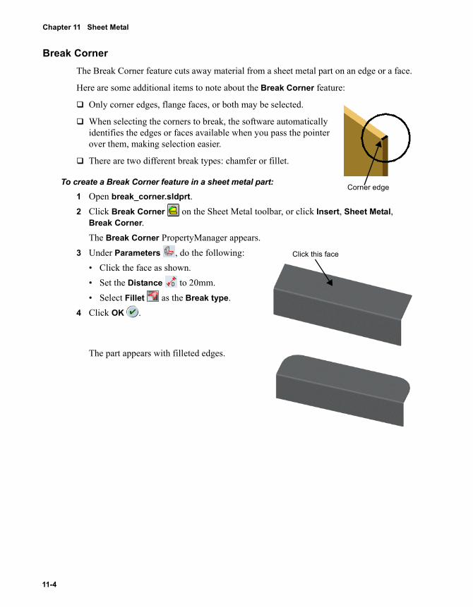
Chapter 11 Sheet Metal
Break CornerThe Break Corner feature cuts away material from a sheet metal part on an edge or a face.
Here are some additional items to note about the Break Corner feature:
� Only corner edges, flange faces, or both may be selected.
� When selecting the corners to break, the software automatically identifies the edges or faces available when you pass the pointer over them, making selection easier.
� There are two different break types: chamfer or fillet.
To create a Break Corner feature in a sheet metal part: 1 Open break_corner.sldprt.2 Click Break Corner on the Sheet Metal toolbar, or click Insert, Sheet Metal,
Break Corner.The Break Corner PropertyManager appears.
3 Under Parameters , do the following: • Click the face as shown.• Set the Distance to 20mm.• Select Fillet as the Break type.
4 Click OK .
The part appears with filleted edges.
Corner edge
Click this face
11-4
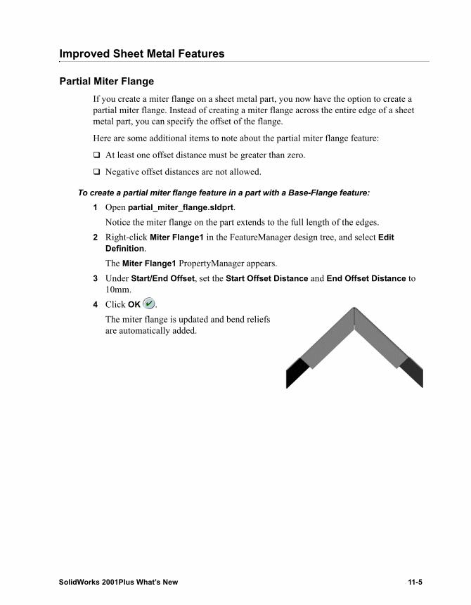
Improved Sheet Metal Features
Partial Miter FlangeIf you create a miter flange on a sheet metal part, you now have the option to create a partial miter flange. Instead of creating a miter flange across the entire edge of a sheet metal part, you can specify the offset of the flange.
Here are some additional items to note about the partial miter flange feature:
� At least one offset distance must be greater than zero.
� Negative offset distances are not allowed.
To create a partial miter flange feature in a part with a Base-Flange feature:1 Open partial_miter_flange.sldprt.
Notice the miter flange on the part extends to the full length of the edges.2 Right-click Miter Flange1 in the FeatureManager design tree, and select Edit
Definition.The Miter Flange1 PropertyManager appears.
3 Under Start/End Offset, set the Start Offset Distance and End Offset Distance to 10mm.
4 Click OK .The miter flange is updated and bend reliefs are automatically added.
SolidWorks 2001Plus What’s New 11-5
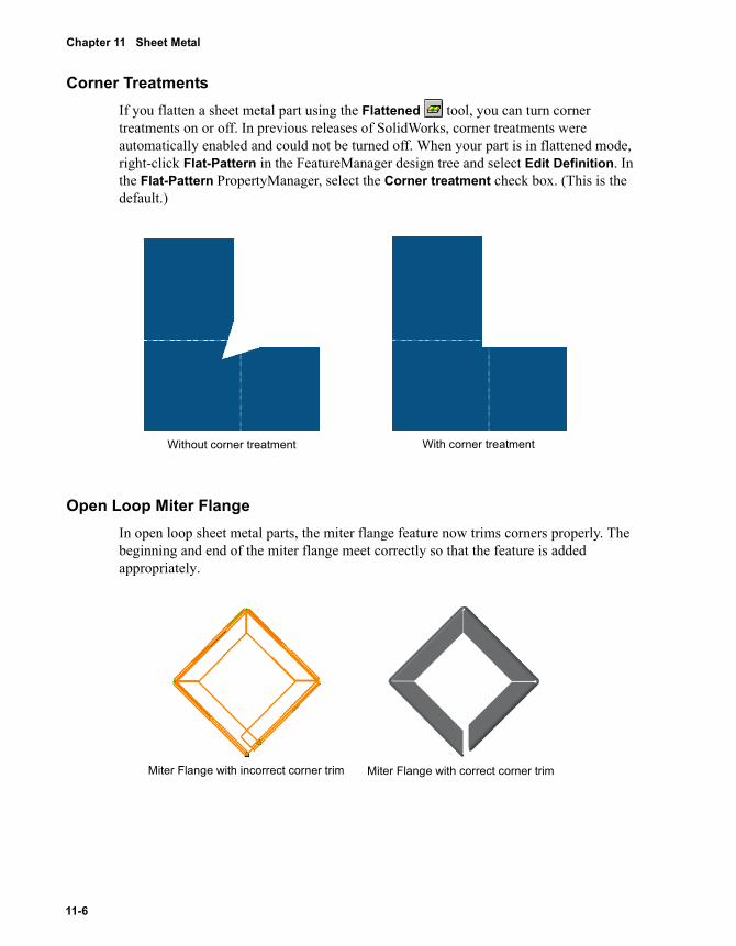
Chapter 11 Sheet Metal
Corner TreatmentsIf you flatten a sheet metal part using the Flattened tool, you can turn corner treatments on or off. In previous releases of SolidWorks, corner treatments were automatically enabled and could not be turned off. When your part is in flattened mode, right-click Flat-Pattern in the FeatureManager design tree and select Edit Definition. In the Flat-Pattern PropertyManager, select the Corner treatment check box. (This is the default.)
Open Loop Miter FlangeIn open loop sheet metal parts, the miter flange feature now trims corners properly. The beginning and end of the miter flange meet correctly so that the feature is added appropriately.
Without corner treatment With corner treatment
Miter Flange with incorrect corner trim Miter Flange with correct corner trim
11-6
A SolidWorks 2001 Service Pack Enhancements
This appendix contains information about new and changed functionality introduced in the Service Packs between the release of SolidWorks 2001 and the release of SolidWorks 2001Plus.
Assemblies
Cam-Follower MatesThe cam-follower mate functionality allows a cylinder or plane to have a tangent mate to a closed series of tangent surfaces, such as would be found on a cam. It allows a point to have a coincident mate to a closed series of tangent surfaces.
Smart FastenersSmart Fasteners allows you to add standard bolts and screws to holes in your assembly with a single command. The fasteners are automatically mated. You can add nuts and washers to the fasteners, and edit the fasteners to change type, length, drive type, and thread display.
Drawings and Detailing
BalloonsYou can specify bent leaders separately for notes and for balloons. Bent leader options were added to Tools, Options, Document Properties, Balloons. Previously, the bent leader options for notes also controlled balloons.
NOTE: Smart Fasteners requires the use of the SolidWorks Toolbox add-in. Please contact your reseller for local pricing and availability
SolidWorks 2001Plus What’s New A-1
Appendix A SolidWorks 2001 Service Pack Enhancements
BlocksThe Block Properties dialog box includes a check box for displaying Note Text. Right-click a block and select Properties. Under Note Text in the Block Properties dialog box, clear the Display check box to hide all notes and balloons in the block. Select the check box to display the text again.
Broken-Out SectionsYou can create broken-out sections in drawing views by sketching a closed profile and specifying a depth. Material is removed to the specified depth to expose inner details of the model. The profile is generally a spline, but it can be any sketched closed profile. You can specify the depth by entering a value or by selecting an edge in a related view.
Cosmetic ThreadsCosmetic threads were inserted automatically into drawings in SolidWorks 2001. Cosmetic threads are now inserted automatically for part drawings, but not for assembly drawings. A Cosmetic thread check box was added to the Insert Model Items dialog box for manual insertion in assembly drawings.
Hole Wizard DimensionsCheck boxes for Hole Wizard Profiles and Hole Wizard Locations were added to the Insert Model Items dialog box under Dimensions for greater control in inserting dimensions into drawings.
Reference DimensionsReference dimensions are now automatically hidden when a feature is suppressed. The dimensions are shown again when the feature is unsuppressed.
eDrawings 2.0
SolidWorks announces the release of eDrawings 2.0 and eDrawings Professional.
With eDrawings 2.0, you can now do the following:
� Create eDrawing files from SolidWorks part or assembly documents, as well as drawing documents
� Open SolidWorks documents in the eDrawings Viewer
� Save eDrawing data to SolidWorks documents in SolidWorks
� View models using standard orthographic views
A-2
With the optional eDrawings Professional, you can do the following:
� Markup files
� Measure models
� Move components in files
� Create cross section views in files
See http://www.solidworks.com/edrawings for more information.
Features
LoftsThe behavior of lofts has changed. If the Maintain Tangency check box under Options is checked, the tangent faces are merged. If the Maintain Tangency option is not checked, the faces are not merged and the surfaces adjust to an angular tolerance of one half a degree. Prior to the SP3 release, if the Maintain Tangency option is checked, the faces are not merged. Any lofts using Maintain Tangency that were created with the SP2 release or before exhibit this behavior.
Hole WizardHelicoil® Inch and Helicoil Metric are now available as standards for Tap holes.
Fundamentals
Selection FilterYou have the option to filter for blocks using the selection filter.
Web FoldersWhen you save assembly documents to a web folder, you have the option to retain the same folder structure in the web folder as the current path for all component documents.
Import/Export
Autodesk InventorSupport now includes through version Autodesk Inventor R4.
CATIA Graphics FilesYou can open CGR part or assembly files in SolidWorks. CGR files contain only graphical information and are for viewing only.
SolidWorks 2001Plus What’s New A-3
Appendix A SolidWorks 2001 Service Pack Enhancements
DXF 3DWhen you import a DXF 3D file that contains multiple bodies or an assembly, SolidWorks creates an assembly document.
IGESIn earlier versions of SolidWorks, a color was assigned to each face in an imported IGES model. Beginning with Service Pack 4, the most prevalent color in the IGES model becomes the part color, and the remaining faces are assigned a face color.
For example, import a block with five blue faces and one red face. Beginning with Service Pack 4, blue is the part color, and the one red face is assigned a face color.
Pro/ENGINEERThe SolidWorks Pro/E translator is available as an add-in. This translator exports SolidWorks part or assembly documents to Pro/ENGINEER part or assembly files.
Solid EdgeSolidWorks supports import of Solid Edge parts up to Solid Edge version 9.
Unigraphics IIYou can import parts and assemblies from Unigraphics II version 10 through version 17.
Virtue TranslatorThe Virtue translator is available as an add-in. This add-in exports SolidWorks part or assembly documents to Virtue (VTU) streaming graphics files.
Sheet Metal
Bend TablesSolidWorks includes two metric bend tables with default radius and thickness values. The bend allowance values are as follows:
� metric base bend table.xls - no bend allowance values are included.
� table4 - metric bend allowance.xls - sample bend allowance values are included.
Closed CornerIn the Closed Corner PropertyManager, you can select a Corner type of Butt, Overlap, or Underlap.
A-4
SolidWorks Utilities
SolidWorks Utilities is a set of applications that allows you to examine and edit individual parts, and compare the features and solid geometry of pairs of parts. The set of applications is a single, separately purchased add-in to the SolidWorks software; please contact your reseller for local pricing.
Surfaces
The Surface Fill PropertyManager has a new Quality control. This control can improve the appearance of the filled surface by changing the number of patches defining the surface.
SolidWorks 2001Plus What’s New A-5
Index
2D to 3D conversion 3-2–3-102D to 3D toolbar 3-22-point splines 2-113D sketches
jog sketch lines 2-6tangent relations 2-10
Aadd sections in lofts 5-12add sketch relations 2-3advanced component selection 7-9align
grid 2-2sketches 2-2, 3-5
alignment method in patterns 5-5Annotation toolbar 9-10annotations 9-10–9-13
blocks 9-12center marks 9-12dangling 9-5dowel pin symbols 9-10hole callouts 9-12multi-jog leaders 9-10notes 9-13show/hide 1-9
anti-alias edges 1-8assemblies 7-2–7-11
delete components 7-8edit part in context 7-10
explode lines 7-7exploded 7-8interior parts 7-9large assembly mode 7-11mate diagnostics 7-3mates 7-2performance 1-10transparency 1-7, 7-9
AutoCAD line fonts 10-8autosize planes 1-3, 4-4auxiliary sketches 3-5
Bbase scales on export 10-7blocks 9-12, 10-4branch multi-jog leaders 9-11break corners in sheet metal 11-4break dimension lines 9-8
Ccancel sketch 2-2center marks 9-12center text in dimensions 9-8chain, select 3-2chamfer dimensions 9-9Chinese (GB) dimensioning standard 9-5circular edges in new mates 7-2combs 2-9
SolidWorks 2001Plus What’s New Index-1
components 7-4–7-11default selection 7-10interior 7-9mirror 7-4move and rotate 7-4
composite curves 4-8ConfigurationManager 7-8configurations 8-2–8-7
design table icon 8-7end conditions 8-2equations 8-4external sketch relations 8-6individual features 8-2nested 8-7sketch dimensions 8-5sketch planes 8-3sketch relations 8-4
Confirmation Corner 2-2conversion, 2D to 3D 3-2–3-10corner treatments 11-6count on view scales 10-7create new sketch 3-3crosshatches on import 10-5curves
composite 4-8patterns 5-4projected 4-6show/hide 1-9sketch 2-9STEP files 10-9
customize tolerance 10-3cut 3-4, 3-9
Ddangling dimensions 9-5dashed line font import 10-6data units on import 10-6default
component selection 7-10display type in drawings 9-2document font 9-13
deletefaces on solids 5-16faces on surfaces 6-8sketch relations 2-4
derived parts 6-2design table icon 8-7
detailing 9-5–9-13annotations 9-10Chinese (GB) standard 9-5dimensions 9-5
diagnosticsimport 10-2mates 7-3
dimensions 9-5–9-9break witness lines 9-8center text 9-8chamfer 9-9configurations 8-5dangling 9-5favorites 9-6Fit tolerances 9-8parentheses 9-8section lines in drawings 9-9styles 9-6
displayanti-alias edges 1-8drawings 1-10HLR edges in shaded mode 1-9, 9-2middle mouse wheel 1-9remove detail during zoom/pan/rotate 1-10shaded mode in drawings 1-9, 9-2shaded planes 4-5shadows 1-7sketch relations 2-4transparency in assemblies 1-7zebra stripes 1-8
dowel pin symbols 9-10draft analysis 5-18drawings 9-2–9-4
explode lines 9-4hide components 9-3hide edges 9-4HLR edges in shaded mode 1-10, 9-2open 9-2print 1-6RapidDraft 9-3shaded mode 1-10, 9-2show edges 9-4
DXF/DWG 10-4–10-8attributes 10-4AutoCAD line fonts 10-8base scale 10-7blocks 10-4count 10-7
Index-2
crosshatches 10-5dashed line font import 10-6data units 10-6export scale option 10-7font import 10-5import for conversion to 3D 3-2view scale 10-7
Eend conditions in configurations 8-2entity check on import 10-2equations in configurations 8-4errors
assembly mates 7-3repair import 10-2repair sketch 3-3
existing sketch relations 2-3exit sketch 2-2explode lines 7-7
assemblies 7-6drawings 9-4sketch tools 2-6
export options, STEP files 10-9extract sketch entities 3-3, 3-4extrude 3-4, 3-8
Ffaces to pattern 5-3favorite dimensions 9-6features 5-2–5-17
2D to 3D conversion 3-8configurations 8-2cut 3-9draft 5-18extrude 3-8, 5-14fillets 5-7pattern 5-2sheet metal 11-2–11-6sweeps and lofts 5-2
fillets 5-7–5-11curvature continuous 5-7fillet by feature 5-11hold lines 5-7sheet metal 11-4sketch 2-3variable radius control points 5-9zebra stripes 5-9
Fit tolerances 9-8flanges 11-5
flipdowel pin symbols 9-10pictures on sketch planes 2-7sketch text 2-8
fold sketches 3-5font import 10-5Font toolbar 9-13force assembly transparency 7-9
Ggaps
break dimension lines 9-8import diagnosis 10-2
GB dimensioning standard 9-5geometry
import wireframe in STEP 10-9reference 4-2–4-8
grids, align 2-2
Hheader/footer 1-4hems 11-2hide
components 9-3dangling dimensions 9-5edges 9-4
HLR edges in shaded mode 1-9, 9-2hold lines 5-7hole callouts 9-12hole wizard 5-15
Iimport/export 10-2–10-10
3D curves 10-9attributes 10-4AutoCAD line fonts 10-8blocks 10-4crosshatches 10-5customize tolerance 10-3dashed line font import 10-6data units 10-6diagnosis 10-2DXF/DWG files 10-4–10-8entity checks 10-2export scale option 10-7font import 10-5gaps 10-2import diagnosis 10-2import options 10-2
SolidWorks 2001Plus What’s New Index-3
improve geometry 10-2repair errors 10-2STEP files 10-9
improve geometry 10-2insert pictures on sketch planes 2-7inspect curvature 2-9interior parts 7-9
Jjog
multi-jog leaders 9-11sheet metal 11-3sketch lines 2-6
Llarge assembly mode 7-11layers 9-13leaders
multi-jog 9-10notes 9-13
library features 1-10lines
jog 2-6split 4-8weights in printing 1-5
lofts 5-2, 5-12, 5-13
Mmacros 1-7margins 1-5mates 7-2–7-4
diagnostics 7-3new selections 7-2surfaces 7-2
measure 6-4menus
shortcut 1-3Sketch Settings 2-2, 2-5Sketch Tools 2-2, 3-2
middle mouse wheel 1-9mirror
components 7-4curve-driven patterns 5-4
miter flangeopen loop 11-6partial 11-5
move components 7-4
move/copyoverride dimensions 2-5surfaces 6-6
multi-jog leaders 9-10
Nnested configurations 8-7non-planar surfaces 5-15notes 9-13not-satisfied mates 7-3
Ooffset from surface 5-14open
drawings from models 9-2drawings in parts 3-2
optionsanti-alias display 1-8break dimension gap 9-8center dimensions 9-8color of HLR edges in shaded mode 1-9default display types 9-2hide components 9-3import 10-2large assembly mode 7-11override dims on drag 2-5transparency in assemblies 7-10
Pparentheses on tolerances 9-8parts 6-2–6-4
converted from 2D 3-5converted from drawings 3-2derived 6-2edit in assemblies 7-10section views 6-4split 6-2
patchboundaries 6-5faces 6-8
patterns 5-2–5-6curve-driven 5-4faces to pattern 5-3
perform full entity check and repair errors 10-2performance
assemblies 1-10large assemblies 7-11
pictures on sketch planes 2-7
Index-4
planesautosize 1-3, 4-4creation 4-2display 4-6edit sketch planes 2-2mirror 7-4pictures on sketch planes 2-7shaded 1-2transparent shaded 4-5
previewsshaded in sweeps and lofts 5-2simplify splines 2-10
printdrawings 1-6header/footer 1-4line weights 1-5margins 1-5
projectcurves 4-6sketch onto faces 4-6sketch onto sketch 4-6
projection tool 4-6properties in configurations 8-2PropertyManager 1-11
add relations 2-4block 9-12center mark 9-12chamfer dimensions 9-9dimension 9-8features 5-2fillets 5-11hole callout 9-12list of commands 1-11mirror components 7-4note 9-13projected curve 4-6sketch fillet 2-3sketch picture 2-7sketch plane 2-2surfaces 6-6zebra stripes 1-8, 6-5
RRapidDraft drawings 9-3reference geometry 4-2–4-8
autosize planes 4-4composite curves 4-8planes 4-2–4-6projected curves 4-6
split lines 4-8transparent shaded planes 4-5
relationsadd 2-4configurations 8-4display/delete 2-4external sketch relations 8-6sketch entities 2-3tangent splines 2-11
repairerrors on import 10-2sketches 3-3
replacefaces in surfaces 6-8faces on solids 5-16
rotatecenter marks 9-12components 7-4pictures on sketch planes 2-7surfaces 6-6
route lines 2-6, 7-6, 7-7Routing toolbar 2-6, 7-7Ssatisfied mates 7-3scales on export 10-7section
lines in drawings 9-9properties 6-4views of models 6-4
select chain 3-2shaded mode
drawings 9-2HLR edges 1-9
shaded planes 1-2, 4-5shadows 1-7sheet metal 11-2–11-6
break corners 11-4corner treatments 11-6hems 11-2jog 11-3open loop miter flange 11-6partial miter flange 11-5
Sheet Metal toolbar 11-2shortcut menus 1-3show edges 9-4show/hide
annotations 1-9curves 1-9sketches 1-9
SolidWorks 2001Plus What’s New Index-5
simplify splines 2-10sketch planes
configurations 8-3edit 2-2insert pictures 2-7
sketches 2-2–2-11, 3-2–3-72D to 3D conversion 3-2align grid 2-2auxiliary 3-5Confirmation Corner 2-2create new 3-3cut 3-4edit sketch planes 2-2explode lines 2-6extract 3-3extrude 3-4fillets 2-3fold 3-5imported drawings 3-2insert pictures 2-7jog sketch lines 2-6menus 2-2override dims on drag 2-5relations 2-3, 2-11repair 3-3select chain 3-2show/hide 1-9splines 2-10text on curves 2-8
splines 2-10split
lines 4-8parts 6-2
standardsChinese (GB) 9-5Fit tolerances 9-8
STEP files 10-9surfaces 6-5–6-9
delete faces and patch 6-8move, rotate, and copy 6-6new mates 7-2non-planar 5-15patch boundaries 6-5replace faces 6-8side tangency 5-13zebra stripes 6-5
sweeps 5-2
Ttags in notes 9-13tangent
3D lines 2-10loft guide curves 5-13mates 7-2spline end points 2-11zebra stripes 6-5
text, sketch on curves 2-8tolerances
customize on import 10-3dimensions 9-8splines 2-10
toolbars 1-102D to 3D 3-2, 3-5Annotation 9-10Font 9-13Routing 2-6Sheet Metal 11-2
translate surface 5-14transparency in assemblies 1-7, 7-9transparent shaded planes 4-5truncated faces 6-4two-point splines 2-11
Uunits of measure 1-2
Vvariable radius control points 5-9, 5-10
Wwitness lines 9-8
Zzebra stripes
curvature continuous fillets 5-9display 1-8patch boundaries 6-5surface boundaries 6-5
Index-6
SolidWorks 2001Plus Document Order Form
Getting Started Manual
SolidWorks will ship the SolidWorks 2001Plus Getting Started manual, as ordered on this form, to registered customers who have upgraded or are on the SolidWorks Subscription Service plan. Orders can be processed only if all information is received. Type or print clearly.Quantity required____________________________________________
Serial Numbers______________________________________________
Include a serial number for each set requested. (For example: 0000 0000 1234 1234)Attach additional sheet if necessary.
Language required:
Please send my package to:Company__________________________________________________________
Attention__________________________________________________________
Address___________________________________________________________
__________________________________________________________________
___________________________________Country________________________
Telephone Number____________________
� English � Italian� French � Russian� German � Spanish
Mail your request to:SolidWorks CorporationAttn: Books300 Baker AvenueConcord, MA 01742 USA
Fax your request to:+1-978-371-4996
Order online:http://www.solidworks.com/docorders
SWINS032ENG