Embed Size (px)
DESCRIPTION
gg
Citation preview

Cartesian Tube Profiling3D Modeling Guidelines
March 2013

- pg 2 of 21 -Table of Contents3 Design Checklist
3 Request for Quote: Checklist
4 Inquiry Documents
5 Preparing SolidWorks for Modeling
6 Weldment Modeling: Step-by-Step Instructions
10 Weldment Modeling: Cutlist Setup
13 Using other CAD packages: Best Practices
14 Bending: Information and Guidelines
15 Bending: Die Chart
16 Weldment Design: Square Tubes
17 Weldment Design: Trimming Options and Guidelines
18 Weldment Design: Special Design Considerations
20 SAE Student Projects
- pg 3 of 21 -
Weldment profiles need to match the material. Ensure wall thickness offset are correct, and geometry is accurate 1. and For square tubes, ensure that corner radii are correct.Ensure that all individual parts have a unique tube number in your cutlist. Match the part number to the balloon 2. number when possible.Please ensure that your assembly drawing is legible. Balloon lines should not cross, and need to be able to read 3. clearly. Please avoid the use of Auto-Balloon functions. Use the provided Sample Material List as a basis for your tube kit material list to ensure that you include Quan-4. tity, Outside Dimension, Wall Thickness, tube type, approximate length, and any mid part features (holes, slots or bends).Confirm that all nodes are trimmed correctly and in the order to be manufactured. Check that there are no hollow 5. nodes or extended trims.Our process takes the profile path directly from your model. So the cut part is entirely dependant on the accuracy 6. of the 3D data provided to us. Ensure that each tube is included, and modeled correctly (tube size, wall thickness, etc in model matches design intent). All bent tubes must follow our bend constraints: bend radii for a given wall thickness, distance from bend to end 7. of part, distance between bends, bend profile tangency. If using a 3D model software other than SolidWorks, your neutral format files are exported as solid bodies, NOT 8. surface bodies. Square tube require a minimum of 0.010” offset from the inside face for profiles.9.
Design Checklist Review this checklist and ensure that your design follows the guidelines to ensure an accurate and timely quote and tube kit. The requirements listed are explained in detail in the following pages.
Send 1. pdf of ISO weldment drawing with balloons.• Material List (with all required tube information).• Entire model (Weldment)•We review model2. : Trims, formed tubes, etc and provide quote.Once the model is approved3. : Send individual 001.sldprt files (numbered per balloon and BOM)
The files are described in detail in the following sections.
Request for Quote: ChecklistIn order to provide an accurate and timely quote, we require a specific set of information about your project or design. If you do not currently have a 3D model, we are able to provide technical support. Please see our Services page.
- pg 4 of 21 -
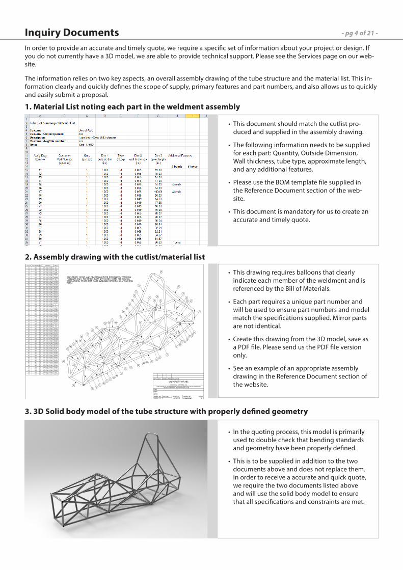
This document should match the cutlist pro-•duced and supplied in the assembly drawing.
The following information needs to be supplied •for each part: Quantity, Outside Dimension, Wall thickness, tube type, approximate length, and any additional features.
Please use the BOM template file supplied in •the Reference Document section of the web-site.
This document is mandatory for us to create an •accurate and timely quote.
This drawing requires balloons that clearly •indicate each member of the weldment and is referenced by the Bill of Materials.
Each part requires a unique part number and •will be used to ensure part numbers and model match the specifications supplied. Mirror parts are not identical.
Create this drawing from the 3D model, save as •a PDF file. Please send us the PDF file version only.
See an example of an appropriate assembly •drawing in the Reference Document section of the website.
In the quoting process, this model is primarily •used to double check that bending standards and geometry have been properly defined.
This is to be supplied in addition to the two •documents above and does not replace them. In order to receive a accurate and quick quote, we require the two documents listed above and will use the solid body model to ensure that all specifications and constraints are met.
1. Material List noting each part in the weldment assembly
2. Assembly drawing with the cutlist/material list
3. 3D Solid body model of the tube structure with properly defined geometry
Inquiry DocumentsIn order to provide an accurate and timely quote, we require a specific set of information about your project or design. If you do not currently have a 3D model, we are able to provide technical support. Please see the Services page on our web-site.
The information relies on two key aspects, an overall assembly drawing of the tube structure and the material list. This in-formation clearly and quickly defines the scope of supply, primary features and part numbers, and also allows us to quickly and easily submit a proposal.
ITEM NO. PARTNUMBER QTY. Description LENGTH
11 011 1 Tube 1.000 x 0.065 12
12 012 1 Tube 1.000 x 0.065 15
13 013 1 Tube 1.000 x 0.065 14.08
14 014 1 Tube 1.000 x 0.065 14.08
15 015 1 Tube 1.000 x 0.095 54.597
16 016 1 Tube 1.000 x 0.095 14
17 017 1 Tube 1.000 x 0.095 100.814
18 018 1 Tube 1.000 x 0.095 20
19 019 1 Tube 1.000 x 0.049 14.883
20 020 1 Tube 1.000 x 0.049 17.383
21 021 1 Tube 1.000 x 0.049 10.078
22 022 1 Tube 1.000 x 0.049 10.078
23 023 1 Tube 1.000 x 0.065 28.018
24 024 1 Tube 1.000 x 0.065 28.018
25 025 1 Tube 1.000 x 0.049 28.638
26 026 1 Tube 1.000 x 0.049 28.638
27 027 1 Tube 1.000 x 0.065 32.213
28 028 1 Tube 1.000 x 0.065 32.213
29 029 1 Tube 1.000 x 0.065 34.665
30 030 1 Tube 1.000 x 0.065 34.665
31 031 1 Tube 1.000 x 0.065 30.599
32 032 1 Tube 1.000 x 0.065 30.599
33 033 1 Tube 1.000 x 0.049 3
34 034 1 Tube 1.000 x 0.049 3
35 035 1 Tube 1.000 x 0.049 12.885
36 036 1 Tube 1.000 x 0.049 12.885
37 037 1 Tube 1.000 x 0.049 15.187
38 038 1 Tube 1.000 x 0.049 15.187
39 039 1 Tube 1.000 x 0.049 34.382
40 040 1 Tube 1.000 x 0.049 34.382
41 041 1 Tube 1.000 x 0.049 11.75
42 042 1 Tube 1.000 x 0.049 19.898
43 043 1 Tube 1.000 x 0.049 10.301
44 044 1 Tube 1.000 x 0.049 10.301
45 045 1 Tube 1.000 x 0.049 14
46 046 1 Tube 1.000 x 0.049 14
47 047 1 Tube 1.000 x 0.049 14.242
48 048 1 Tube 1.000 x 0.049 14.242
49 049 1 Tube 1.000 x 0.049 16.923
50 050 1 Tube 1.000 x 0.049 16.923
51 051 1 Tube 1.000 x 0.049 20.312
52 052 1 Tube 1.000 x 0.049 20.312
53 053 1 Tube 1.000 x 0.049 20.024
54 054 1 Tube 1.000 x 0.049 20.024
55 055 1 Tube 1.000 x 0.049 19.069
56 056 1 Tube 1.000 x 0.049 19.069
57 057 1 Tube 1.000 x 0.049 21.341
58 058 1 Tube 1.000 x 0.049 21.341
59 059 1 Tube 1.000 x 0.049 9.047
60 060 1 Tube 1.000 x 0.049 9.047
61 061 1 Tube 1.000 x 0.049 18.456
62 062 1 Tube 1.000 x 0.049 18.456
63 063 1 Tube 1.000 x 0.049 15.548
64 064 1 Tube 1.000 x 0.049 15.548
65 065 1 Tube 1.000 x 0.049 17.427
66 066 1 Tube 1.000 x 0.049 17.427
67 067 1 Tube 1.000 x 0.049 36.978
68 068 1 Tube 1.000 x 0.049 36.978
69 069 1 Tube 0.875 x 0.049 30.195
70 070 1 Tube 0.875 x 0.049 19.285
71 071 1 Tube 0.875 x 0.049 10.909
72 072 1 Tube 0.875 x 0.049 34.971
73 073 1 Tube 0.875 x 0.049 20.8
74 074 1 Tube 0.875 x 0.049 14.171
XXX
DRAWING
UNIVERSITY OF ABC
X
LINE1
LINE2
LINE3
INIT
1:5 PROJECT
REV NO.DRAWING NO.
REV'N DATE DRAWN APPRVD. DESCRIPTION
PROJECT NO.
WITHOUT PERMISSION FROM UNIVERSITY OF ABC
THIS DRAWING OR THE INFORMATION CONTAINED HEREIN MAY NOT BE REPRODUCED
'C' SCALE:
DRAWN: DATE:
SPRINGFIELD, SOMEWHERE, USA
32
46
23
26
12
14
13
43
4111
40
70
69
44
PURPOSES ONLY. THE MODEL DOES NOT COMPLY WITH SAE RULES &
REGULATIONS. IT HAS BEEN MADE AVAILABLE STRICTLY AS A TEACHING
TOOL.
15
74
16
49
53
45
24
54
50
51
72
73
27
28
58
57
29
18
17
68
67
20
22
21
1966
38
36
64
34
62
30
60
31
65
37
33
59
61
42
35
63
56
55
47
25
71
DISCLAIMER: MODEL AND DRAWING ARE FOR DISCUSSION/ TEACHING
39
- pg 5 of 21 -
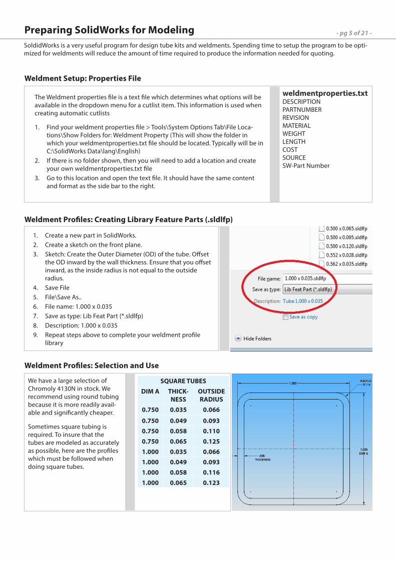
The Weldment properties file is a text file which determines what options will be available in the dropdown menu for a cutlist item. This information is used when creating automatic cutlists
Find your weldment properties file > Tools\System Options Tab\File Loca-1. tions\Show Folders for: Weldment Property (This will show the folder in which your weldmentproperties.txt file should be located. Typically will be in C:\SolidWorks Data\lang\English)If there is no folder shown, then you will need to add a location and create 2. your own weldmentproperties.txt fileGo to this location and open the text file. It should have the same content 3. and format as the side bar to the right.
Create a new part in SolidWorks.1. Create a sketch on the front plane.2. Sketch: Create the Outer Diameter (OD) of the tube. Offset 3. the OD inward by the wall thickness. Ensure that you offset inward, as the inside radius is not equal to the outside radius.Save File 4. File\Save As..5. File name: 1.000 x 0.0356. Save as type: Lib Feat Part (*.sldlfp)7. Description: 1.000 x 0.0358. Repeat steps above to complete your weldment profile 9. library
We have a large selection of Chromoly 4130N in stock. We recommend using round tubing because it is more readily avail-able and significantly cheaper.
Sometimes square tubing is required. To insure that the tubes are modeled as accurately as possible, here are the profiles which must be followed when doing square tubes.
Weldment Setup: Properties File
Weldment Profiles: Creating Library Feature Parts (.sldlfp)
Weldment Profiles: Selection and Use
Preparing SolidWorks for Modeling
weldmentproperties.txtDESCRIPTION PARTNUMBER REVISION MATERIAL WEIGHT LENGTH COST SOURCE SW-Part Number
SQUARE TUBES
DIM A THICK-NESS
OUTSIDE RADIUS
0.750 0.035 0.066
0.750 0.049 0.093
0.750 0.058 0.110
0.750 0.065 0.125
1.000 0.035 0.066
1.000 0.049 0.093
1.000 0.058 0.116
1.000 0.065 0.123
SoldidWorks is a very useful program for design tube kits and weldments. Spending time to setup the program to be opti-mized for weldments will reduce the amount of time required to produce the information needed for quoting.
- pg 6 of 21 -
This guide is to assist designers in preparing information suitable for our tube profiling process. These methods and sug-gestions are specifically for SolidWorks but should be applicable to other 3D cad packages.
Tubing structures are best suited to be built as a ‘weldment’ part. Some advantages are:
one file contains the complete parametric information and therefore can be sent without related attachment files or •libraries
trim and extend features are quick and easy•
profile library of tube sizes is convenient for creating a more ‘automatic’ BOM•
one file to update with any changes to tube sizes or geometry • Before starting your modeling; make sure that you have your weldment library updated and your weldment file in the correct location. See Weldment Profiles: Selection and Use on the previous page.
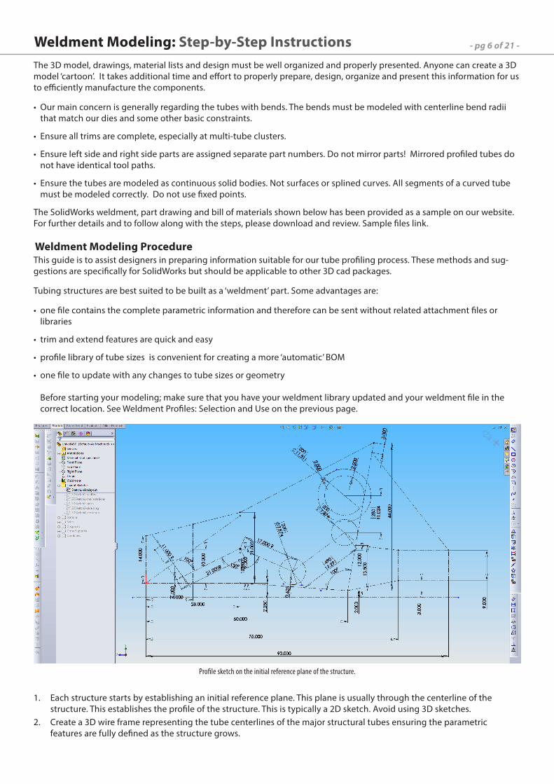
Weldment Modeling: Step-by-Step Instructions
Each structure starts by establishing an initial reference plane. This plane is usually through the centerline of the 1. structure. This establishes the profile of the structure. This is typically a 2D sketch. Avoid using 3D sketches.Create a 3D wire frame representing the tube centerlines of the major structural tubes ensuring the parametric 2. features are fully defined as the structure grows.
Weldment Modeling Procedure
The 3D model, drawings, material lists and design must be well organized and properly presented. Anyone can create a 3D model ‘cartoon’. It takes additional time and effort to properly prepare, design, organize and present this information for us to efficiently manufacture the components.
Our main concern is generally regarding the tubes with bends. The bends must be modeled with centerline bend radii •that match our dies and some other basic constraints.
Ensure all trims are complete, especially at multi-tube clusters. •
Ensure left side and right side parts are assigned separate part numbers. Do not mirror parts! Mirrored profiled tubes do •not have identical tool paths.
Ensure the tubes are modeled as continuous solid bodies. Not surfaces or splined curves. All segments of a curved tube •must be modeled correctly. Do not use fixed points.
The SolidWorks weldment, part drawing and bill of materials shown below has been provided as a sample on our website. For further details and to follow along with the steps, please download and review. Sample files link.
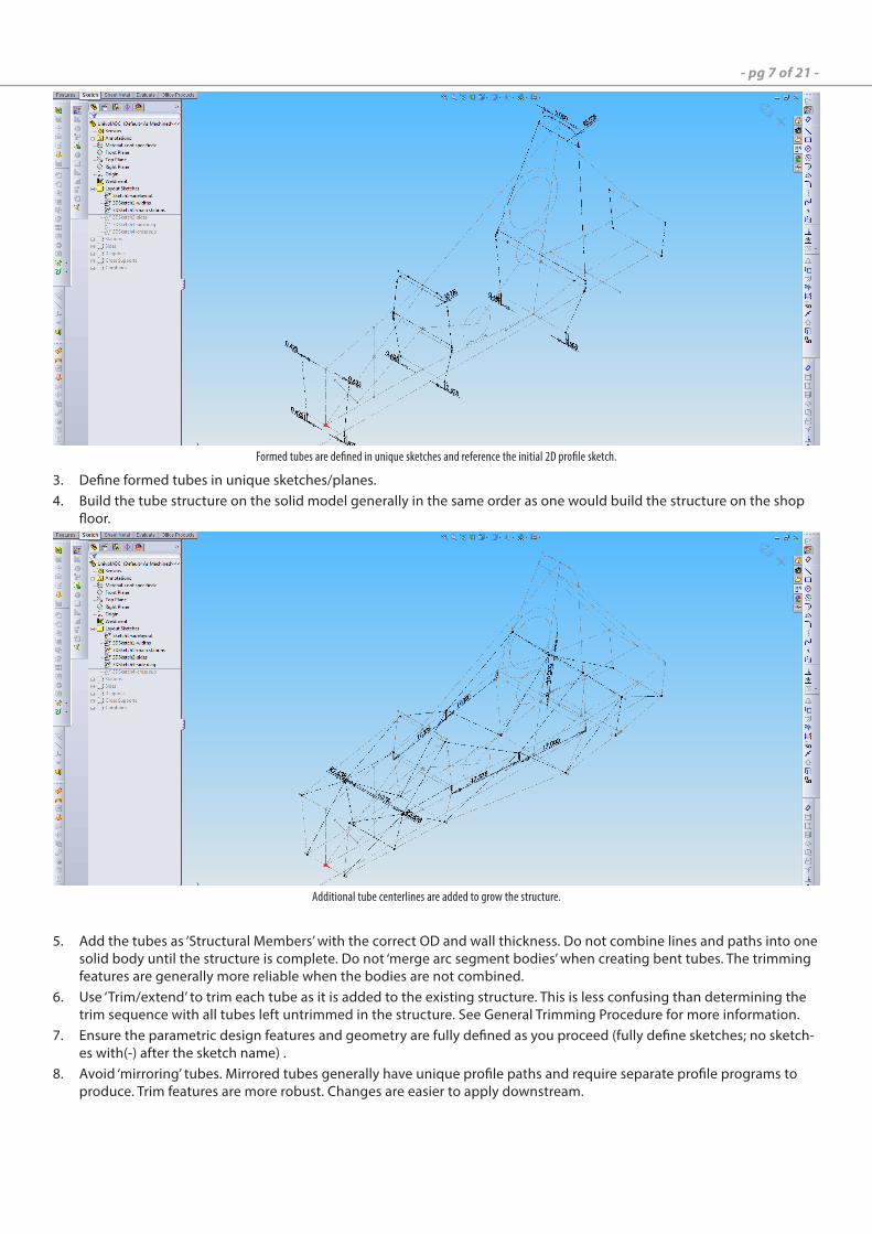
Profile sketch on the initial reference plane of the structure.
- pg 7 of 21 -
Define formed tubes in unique sketches/planes.3. Build the tube structure on the solid model generally in the same order as one would build the structure on the shop 4. floor.
Formed tubes are defined in unique sketches and reference the initial 2D profile sketch.
Additional tube centerlines are added to grow the structure.
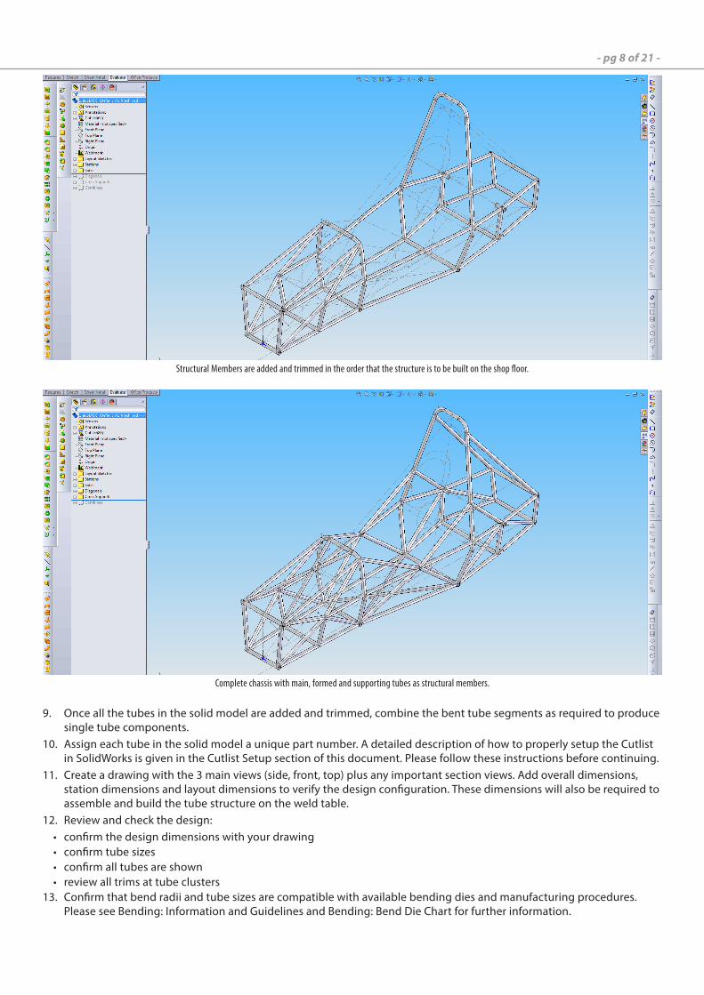
Add the tubes as ‘Structural Members’ with the correct OD and wall thickness. Do not combine lines and paths into one 5. solid body until the structure is complete. Do not ‘merge arc segment bodies’ when creating bent tubes. The trimming features are generally more reliable when the bodies are not combined.Use ‘Trim/extend’ to trim each tube as it is added to the existing structure. This is less confusing than determining the 6. trim sequence with all tubes left untrimmed in the structure. See General Trimming Procedure for more information.Ensure the parametric design features and geometry are fully defined as you proceed (fully define sketches; no sketch-7. es with(-) after the sketch name) .Avoid ‘mirroring’ tubes. Mirrored tubes generally have unique profile paths and require separate profile programs to 8. produce. Trim features are more robust. Changes are easier to apply downstream.
- pg 8 of 21 -
Structural Members are added and trimmed in the order that the structure is to be built on the shop floor.
Once all the tubes in the solid model are added and trimmed, combine the bent tube segments as required to produce 9. single tube components. Assign each tube in the solid model a unique part number. A detailed description of how to properly setup the Cutlist 10. in SolidWorks is given in the Cutlist Setup section of this document. Please follow these instructions before continuing.Create a drawing with the 3 main views (side, front, top) plus any important section views. Add overall dimensions, 11. station dimensions and layout dimensions to verify the design configuration. These dimensions will also be required to assemble and build the tube structure on the weld table.Review and check the design:12. confirm the design dimensions with your drawing•confirm tube sizes•confirm all tubes are shown•review all trims at tube clusters•Confirm that bend radii and tube sizes are compatible with available bending dies and manufacturing procedures. 13. Please see Bending: Information and Guidelines and Bending: Bend Die Chart for further information.
Complete chassis with main, formed and supporting tubes as structural members.
- pg 9 of 21 -
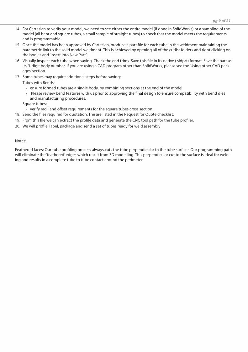
For Cartesian to verify your model, we need to see either the entire model (if done in SolidWorks) or a sampling of the 14. model (all bent and square tubes, a small sample of straight tubes) to check that the model meets the requirements and is programmable.Once the model has been approved by Cartesian, produce a part file for each tube in the weldment maintaining the 15. parametric link to the solid model weldment. This is achieved by opening all of the cutlist folders and right clicking on the bodies and ‘Insert into New Part’.Visually inspect each tube when saving. Check the end trims. Save this file in its native (.sldprt) format. Save the part as 16. its’ 3-digit body number. If you are using a CAD program other than SolidWorks, please see the ‘Using other CAD pack-ages’ section.Some tubes may require additional steps before saving:17. Tubes with Bends:
ensure formed tubes are a single body, by combining sections at the end of the model• Please review bend features with us prior to approving the final design to ensure compatibility with bend dies •and manufacturing procedures.
Square tubes:verify radii and offset requirements for the square tubes cross section.•
Send the files required for quotation. The are listed in the 18. Request for Quote checklist.From this file we can extract the profile data and generate the CNC tool path for the tube profiler.19. We will profile, label, package and send a set of tubes ready for weld assembly20.
Notes:
Feathered faces: Our tube profiling process always cuts the tube perpendicular to the tube surface. Our programming path will eliminate the ‘feathered’ edges which result from 3D modelling. This perpendicular cut to the surface is ideal for weld-ing and results in a complete tube to tube contact around the perimeter.
- pg 10 of 21 -
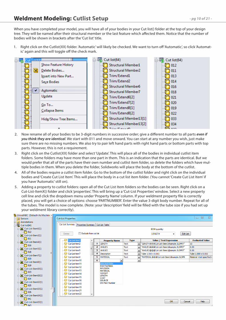
When you have completed your model, you will have all of your bodies in your Cut list() folder at the top of your design tree. They will be named after their structural member or the last feature which affected them. Notice that the number of bodies will be shown in brackets after the ‘Cut list’ title.
Weldment Modeling: Cutlist Setup
Right click on the Cutlist(XX) folder. ‘Automatic’ will likely be checked. We want to turn off ‘Automatic’, so click ‘Automat-1. ic’ again and this will toggle off the check mark.
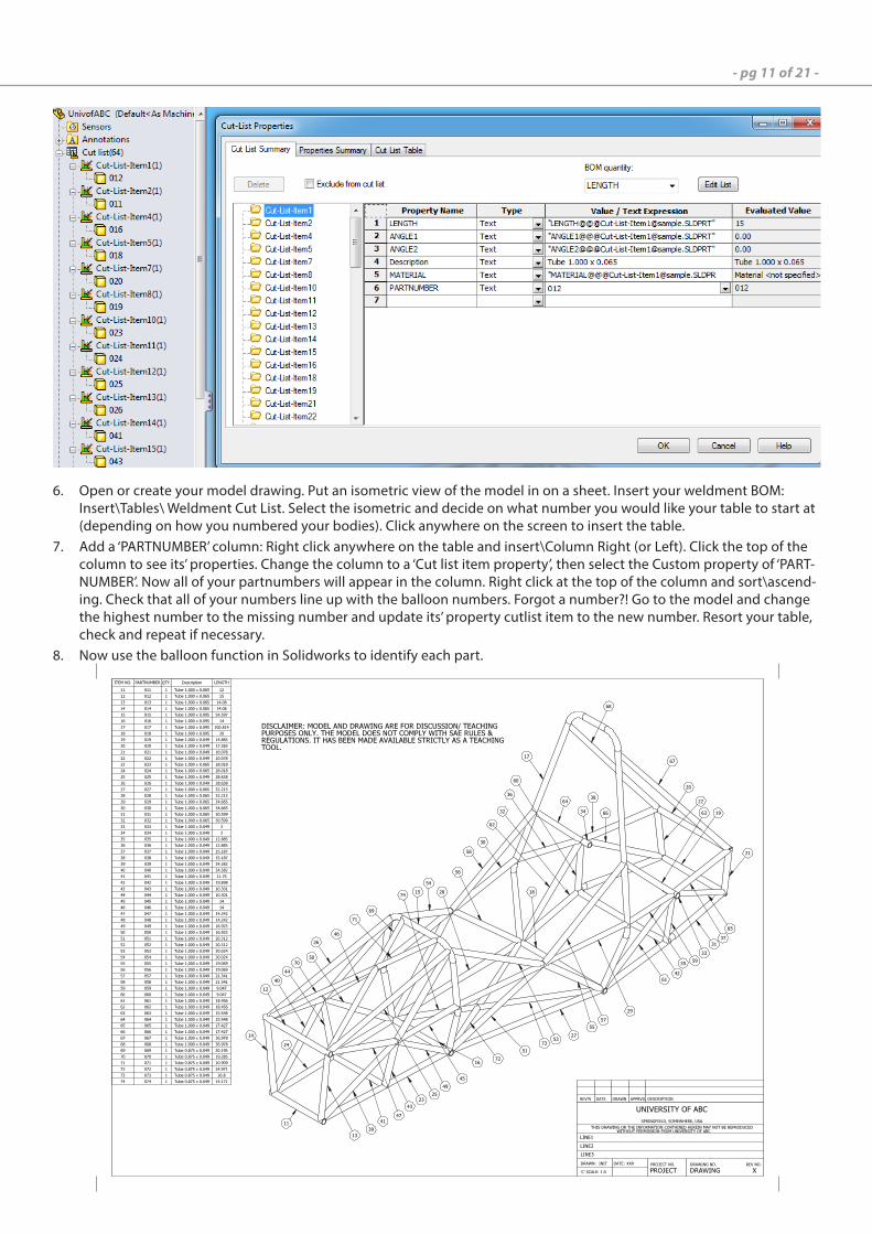
Now rename all of your bodies to be 3-digit numbers in successive order; give a different number to all parts 2. even if you think they are identical. We start with 011 and move onward. You can start at any number you wish, just make sure there are no missing numbers. We also try to pair left hand parts with right hand parts or bottom parts with top parts. However, this is not a requirement.Right click on the Cutlist(XX) folder and select ‘Update’. This will place all of the bodies in individual cutlist item 3. folders. Some folders may have more than one part in them. This is an indication that the parts are identical. But we would prefer that all of the parts have their own number and cutlist item folder, so delete the folders which have mul-tiple bodies in them. When you delete the folder, Solidworks will place the body at the bottom of the cutlist.All of the bodies require a cutlist item folder. Go to the bottom of the cutlist folder and right click on the individual 4. bodies and ‘Create Cut List Item’. This will place the body in a cut list item folder. (You cannot ‘Create Cut List Item’ if you have ‘Automatic’ still on).Adding a property to cutlist folders: open all of the Cut List Item folders so the bodies can be seen. Right click on a 5. Cut-List-ItemX() folder and click ‘properties’. This will bring up a ‘Cut-List Properties’ window. Select a new property cell line and click the dropdown menu under ‘Property Name’ column. If your weldment property file is correctly placed, you will get a choice of options: choose ‘PARTNUMBER’. Enter the value 3-digit body number. Repeat for all of the tubes. The model is now complete. (Note: your ‘description’ field will be filled with the tube size if you had set up your weldment library correctly).
- pg 11 of 21 -
Open or create your model drawing. Put an isometric view of the model in on a sheet. Insert your weldment BOM: 6. Insert\Tables\ Weldment Cut List. Select the isometric and decide on what number you would like your table to start at (depending on how you numbered your bodies). Click anywhere on the screen to insert the table.Add a ‘PARTNUMBER’ column: Right click anywhere on the table and insert\Column Right (or Left). Click the top of the 7. column to see its’ properties. Change the column to a ‘Cut list item property’, then select the Custom property of ‘PART-NUMBER’. Now all of your partnumbers will appear in the column. Right click at the top of the column and sort\ascend-ing. Check that all of your numbers line up with the balloon numbers. Forgot a number?! Go to the model and change the highest number to the missing number and update its’ property cutlist item to the new number. Resort your table, check and repeat if necessary.Now use the balloon function in Solidworks to identify each part.8.
ITEM NO. PARTNUMBER QTY. Description LENGTH
11 011 1 Tube 1.000 x 0.065 12
12 012 1 Tube 1.000 x 0.065 15
13 013 1 Tube 1.000 x 0.065 14.08
14 014 1 Tube 1.000 x 0.065 14.08
15 015 1 Tube 1.000 x 0.095 54.597
16 016 1 Tube 1.000 x 0.095 14
17 017 1 Tube 1.000 x 0.095 100.814
18 018 1 Tube 1.000 x 0.095 20
19 019 1 Tube 1.000 x 0.049 14.883
20 020 1 Tube 1.000 x 0.049 17.383
21 021 1 Tube 1.000 x 0.049 10.078
22 022 1 Tube 1.000 x 0.049 10.078
23 023 1 Tube 1.000 x 0.065 28.018
24 024 1 Tube 1.000 x 0.065 28.018
25 025 1 Tube 1.000 x 0.049 28.638
26 026 1 Tube 1.000 x 0.049 28.638
27 027 1 Tube 1.000 x 0.065 32.213
28 028 1 Tube 1.000 x 0.065 32.213
29 029 1 Tube 1.000 x 0.065 34.665
30 030 1 Tube 1.000 x 0.065 34.665
31 031 1 Tube 1.000 x 0.065 30.599
32 032 1 Tube 1.000 x 0.065 30.599
33 033 1 Tube 1.000 x 0.049 3
34 034 1 Tube 1.000 x 0.049 3
35 035 1 Tube 1.000 x 0.049 12.885
36 036 1 Tube 1.000 x 0.049 12.885
37 037 1 Tube 1.000 x 0.049 15.187
38 038 1 Tube 1.000 x 0.049 15.187
39 039 1 Tube 1.000 x 0.049 34.382
40 040 1 Tube 1.000 x 0.049 34.382
41 041 1 Tube 1.000 x 0.049 11.75
42 042 1 Tube 1.000 x 0.049 19.898
43 043 1 Tube 1.000 x 0.049 10.301
44 044 1 Tube 1.000 x 0.049 10.301
45 045 1 Tube 1.000 x 0.049 14
46 046 1 Tube 1.000 x 0.049 14
47 047 1 Tube 1.000 x 0.049 14.242
48 048 1 Tube 1.000 x 0.049 14.242
49 049 1 Tube 1.000 x 0.049 16.923
50 050 1 Tube 1.000 x 0.049 16.923
51 051 1 Tube 1.000 x 0.049 20.312
52 052 1 Tube 1.000 x 0.049 20.312
53 053 1 Tube 1.000 x 0.049 20.024
54 054 1 Tube 1.000 x 0.049 20.024
55 055 1 Tube 1.000 x 0.049 19.069
56 056 1 Tube 1.000 x 0.049 19.069
57 057 1 Tube 1.000 x 0.049 21.341
58 058 1 Tube 1.000 x 0.049 21.341
59 059 1 Tube 1.000 x 0.049 9.047
60 060 1 Tube 1.000 x 0.049 9.047
61 061 1 Tube 1.000 x 0.049 18.456
62 062 1 Tube 1.000 x 0.049 18.456
63 063 1 Tube 1.000 x 0.049 15.548
64 064 1 Tube 1.000 x 0.049 15.548
65 065 1 Tube 1.000 x 0.049 17.427
66 066 1 Tube 1.000 x 0.049 17.427
67 067 1 Tube 1.000 x 0.049 36.978
68 068 1 Tube 1.000 x 0.049 36.978
69 069 1 Tube 0.875 x 0.049 30.195
70 070 1 Tube 0.875 x 0.049 19.285
71 071 1 Tube 0.875 x 0.049 10.909
72 072 1 Tube 0.875 x 0.049 34.971
73 073 1 Tube 0.875 x 0.049 20.8
74 074 1 Tube 0.875 x 0.049 14.171
XXX
DRAWING
UNIVERSITY OF ABC
X
LINE1
LINE2
LINE3
INIT
1:5 PROJECT
REV NO.DRAWING NO.
REV'N DATE DRAWN APPRVD. DESCRIPTION
PROJECT NO.
WITHOUT PERMISSION FROM UNIVERSITY OF ABC
THIS DRAWING OR THE INFORMATION CONTAINED HEREIN MAY NOT BE REPRODUCED
'C' SCALE:
DRAWN: DATE:
SPRINGFIELD, SOMEWHERE, USA
32
46
23
26
12
14
13
43
4111
40
70
69
44
PURPOSES ONLY. THE MODEL DOES NOT COMPLY WITH SAE RULES &
REGULATIONS. IT HAS BEEN MADE AVAILABLE STRICTLY AS A TEACHING
TOOL.
15
74
16
49
53
45
24
54
50
51
72
73
27
28
58
57
29
18
17
68
67
20
22
21
1966
38
36
64
34
62
30
60
31
65
37
33
59
61
42
35
63
56
55
47
25
71
DISCLAIMER: MODEL AND DRAWING ARE FOR DISCUSSION/ TEACHING
39

- pg 12 of 21 -
Check the profiles for the library feature parts. If there is no description field, ensure that the description field has 1. been filled out. Resave all of the library feature parts once this has been completed. For complete instructions on setting up library feature parts, please see the Preparing Solidworks for Modeling section.Bring the model tree up by dragging the rollback bar in your DesignTree up to the first structural member. You 2. will need to open each structural member individually and toggle the library feature (choose a different size, then toggle back to the desired size); this will add the correct description of the tube to your cutlist. Drag the rollback bar down to the next structural member and repeat for all tubes.Next, select all of the cutlist item folders and delete them (you may need to turn off ‘automatic’). This will leave the 3. cutlist folder with only bodies. Right click the main cutlist folder and select ‘update’. This will put all of the bodies into cutlist item folders. Now check the properties of each folder and notice that there will now be a description present.
Cutlist Setup: Steps to take if no description field is present.
- pg 13 of 21 -
Our preferred CAD package is SolidWorks due to it’s tools for weldments and tube structures but there are a large number of additional CAD programs that may be used. We will take a neutral file format and import it into SolidWorks in order to get the cutting toolpaths.
There are some common problems when creating files in other CAD programs and importing them into SolidWorks:
Using other CAD packages: Best Practices
‘Sweeps’ are used to make profiles along a line to make the tubes. Sometimes the profiles’ sketch planes are not per-•pendicular to the line in which they are being swept. This in reality creates elliptical tubing!
Bent tubes: lines before and after a bend/radius need to be tangent to that radius!•
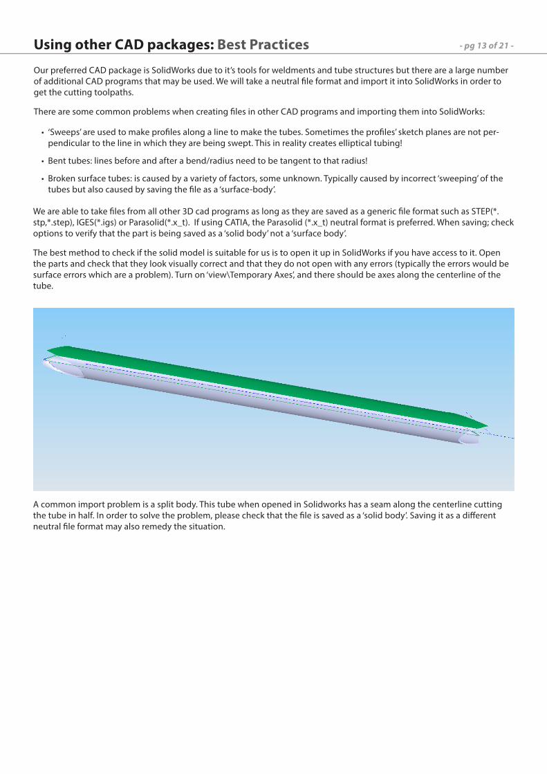
Broken surface tubes: is caused by a variety of factors, some unknown. Typically caused by incorrect ‘sweeping’ of the •tubes but also caused by saving the file as a ‘surface-body’.
We are able to take files from all other 3D cad programs as long as they are saved as a generic file format such as STEP(*.stp,*.step), IGES(*.igs) or Parasolid(*.x_t). If using CATIA, the Parasolid (*.x_t) neutral format is preferred. When saving; check options to verify that the part is being saved as a ‘solid body’ not a ‘surface body’.
The best method to check if the solid model is suitable for us is to open it up in SolidWorks if you have access to it. Open the parts and check that they look visually correct and that they do not open with any errors (typically the errors would be surface errors which are a problem). Turn on ‘view\Temporary Axes’, and there should be axes along the centerline of the tube.
A common import problem is a split body. This tube when opened in Solidworks has a seam along the centerline cutting the tube in half. In order to solve the problem, please check that the file is saved as a ‘solid body’. Saving it as a different neutral file format may also remedy the situation.
- pg 14 of 21 -
All of the tubes are bent with an electric rotary bender. There is no mandrel on the bender so there are limitations to •the size of the bend radius relative to the thickness of the tube.
Bend radii must be selected and modeled corresponding to the dies we have available and appropriate for the tube OD •/ wall thickness / bend angle required. See the attached document.
There is also a minimum distance between bends of 4-5” typically for out of plane bends. This distance can be slightly •reduced if the bends are in the same plane.
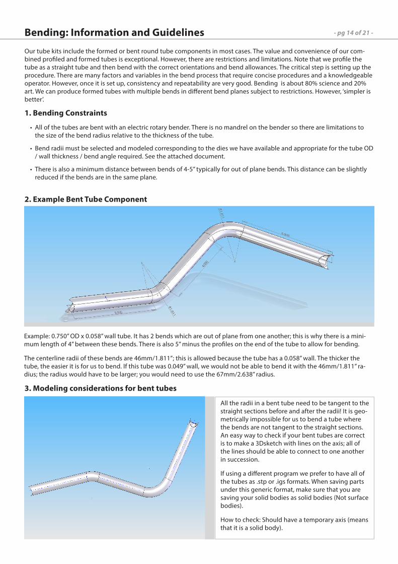
Example: 0.750” OD x 0.058” wall tube. It has 2 bends which are out of plane from one another; this is why there is a mini-mum length of 4” between these bends. There is also 5” minus the profiles on the end of the tube to allow for bending.
The centerline radii of these bends are 46mm/1.811”; this is allowed because the tube has a 0.058” wall. The thicker the tube, the easier it is for us to bend. If this tube was 0.049” wall, we would not be able to bend it with the 46mm/1.811” ra-dius; the radius would have to be larger; you would need to use the 67mm/2.638” radius.
All the radii in a bent tube need to be tangent to the straight sections before and after the radii! It is geo-metrically impossible for us to bend a tube where the bends are not tangent to the straight sections. An easy way to check if your bent tubes are correct is to make a 3Dsketch with lines on the axis; all of the lines should be able to connect to one another in succession.
If using a different program we prefer to have all of the tubes as .stp or .igs formats. When saving parts under this generic format, make sure that you are saving your solid bodies as solid bodies (Not surface bodies).
How to check: Should have a temporary axis (means that it is a solid body).
1. Bending Constraints
2. Example Bent Tube Component
3. Modeling considerations for bent tubes
Our tube kits include the formed or bent round tube components in most cases. The value and convenience of our com-bined profiled and formed tubes is exceptional. However, there are restrictions and limitations. Note that we profile the tube as a straight tube and then bend with the correct orientations and bend allowances. The critical step is setting up the procedure. There are many factors and variables in the bend process that require concise procedures and a knowledgeable operator. However, once it is set up, consistency and repeatability are very good. Bending is about 80% science and 20% art. We can produce formed tubes with multiple bends in different bend planes subject to restrictions. However, ‘simpler is better’.
Bending: Information and Guidelines
- pg 15 of 21 -
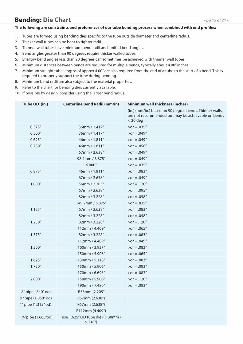
The following are constraints and preferences of our tube bending process when combined with end profiles:
Tubes are formed using bending dies specific to the tube outside diameter and centerline radius.1. Thicker wall tubes can be bent to tighter radii.2. Thinner wall tubes have minimum bend radii and limited bend angles.3. Bend angles greater than 90 degrees require thicker walled tubes.4. Shallow bend angles less than 20 degrees can sometimes be achieved with thinner wall tubes.5. Minimum distances between bends are required for multiple bends, typically about 4.00” inches.6. Minimum straight tube lengths of approx 4.00” are also required from the end of a tube to the start of a bend. This is 7. required to properly support the tube during bending.Minimum bend radii are also subject to the material properties.8. Refer to the chart for bending dies currently available.9. If possible by design, consider using the larger bend radius.10.
Bending: Die Chart
Tube OD (in.) Centerline Bend Radii (mm/in) Minimum wall thickness (inches)
(in.) (mm/in.) based on 90 degree bends. Thinner walls are not recommended but may be achievable on bends < 20 deg
0.375” 36mm / 1.417” >or = .035”
0.500” 36mm / 1.417” >or = .049”
0.625” 46mm / 1.811” >or = .049”
0.750” 46mm / 1.811” >or = .058”
67mm / 2.638” >or = .049”
98.4mm / 3.875” >or = .049”
6.000” >or = .035”
0.875” 46mm / 1.811” >or = .083”
67mm / 2.638” >or = .049”
1.000” 56mm / 2.205” >or = .120”
67mm / 2.638” >or = .095”
82mm / 3.228” >or = .058”
149.2mm / 5.875” >or = .035”
1.125” 67mm / 2.638” >or = .083”
82mm / 3.228” >or = .058”
1.250” 82mm / 3.228” >or = .120”
112mm / 4.409” >or = .065”
1.375” 82mm / 3.228” >or = .083”
112mm / 4.409” >or = .049”
1.500” 100mm / 3.937” >or = .083”
150mm / 5.906” >or = .065”
1.625” 130mm / 5.118” >or = .083”
1.750” 150mm / 5.906” >or = .083”
170mm / 6.693” >or = .083”
2.000” 150mm / 5.906” >or = .120”
190mm / 7.480” >or = .083”
½” pipe (.840” od) R56mm (2.205”
¾” pipe (1.050” od) R67mm (2.638”)
1” pipe (1.315” od) R67mm (2.638”)
R112mm (4.409”)
1 ¼”pipe (1.660”od) use 1.625” OD tube die (R130mm / 5.118”)
- pg 16 of 21 -Weldment Design: Square Tubes
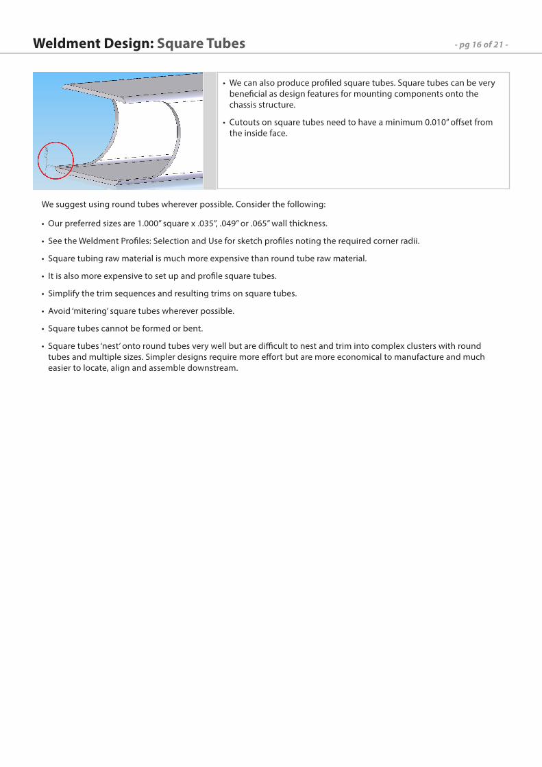
We can also produce profiled square tubes. Square tubes can be very •beneficial as design features for mounting components onto the chassis structure.
Cutouts on square tubes need to have a minimum 0.010” offset from •the inside face.
We suggest using round tubes wherever possible. Consider the following:
Our preferred sizes are 1.000” square x .035”, .049” or .065” wall thickness.•
See the Weldment Profiles: Selection and Use for sketch profiles noting the required corner radii.•
Square tubing raw material is much more expensive than round tube raw material. •
It is also more expensive to set up and profile square tubes.•
Simplify the trim sequences and resulting trims on square tubes.•
Avoid ‘mitering’ square tubes wherever possible.•
Square tubes cannot be formed or bent.•
Square tubes ‘nest’ onto round tubes very well but are difficult to nest and trim into complex clusters with round •tubes and multiple sizes. Simpler designs require more effort but are more economical to manufacture and much easier to locate, align and assemble downstream.
- pg 17 of 21 -Weldment Design: Trimming Options and GuidelinesThe sequence and options used when trimming is incredibly important to the weldment design. Below are several common areas where errors occur in weldments and need to be done in the correct method and sequence. In some situations, having incorrect trims negates having CNC profiled tubes. Proper trims will allow for easier and more accurate fabrication. Please review the situations below carefully to ensure that you follow the proper procedure. The majority of models which we receive have most of their errors in the trims. Missing trims, improper trims and hollow nodes are the most common mistakes.
In SolidWorks, the general procedure for trimming is as follows. In certain situations, different options are used in order to create a proper trim.
As you build up the weldment, create and place structural members (tubes) in the order that you will be fabricating 1. the structure.Use a unique structural member for each tube. Do NOT put all of the same size tube in one structural member •definition. Using a unique structural member allows for easier change of tube size.Trim the tubes as you create structural members, rather than doing all of the trims at the end of the design tree. •This limits missed trims in tube clusters.Trim in the order you will place tubes. Ensure that there are no hollow nodes in any cluster.•Trim a single tube at a time, both ends. If you are having difficulty with a trim, do one end at a time. DO NOT trim 2. multiple tubes in one operation, this leads to confusion, errors and limits ability to parametrically change the model. Having organized trims allows for ease of modeling and verification.For options, use the ‘Trim to Body’, do not ‘Allow Extension’ settings as a base point. If trimming to bodies does 3. not create a correct resultant trim, set the Trimming Boundary to Face/Plane. Check the bodies to keep and the trimmed bodies to discard. Review that the trims have been completed using the surface are correct.
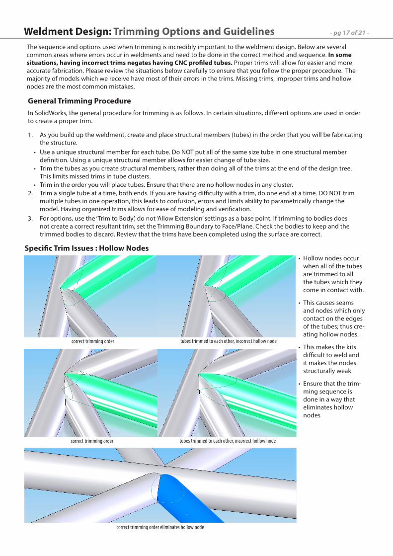
Specific Trim Issues : Hollow Nodes
General Trimming Procedure
correct trimming order tubes trimmed to each other, incorrect hollow node
correct trimming order tubes trimmed to each other, incorrect hollow node
correct trimming order eliminates hollow node
Hollow nodes occur •when all of the tubes are trimmed to all the tubes which they come in contact with.
This causes seams •and nodes which only contact on the edges of the tubes; thus cre-ating hollow nodes.
This makes the kits •difficult to weld and it makes the nodes structurally weak.
Ensure that the trim-•ming sequence is done in a way that eliminates hollow nodes
- pg 18 of 21 -Weldment Design: Special Design Considerations
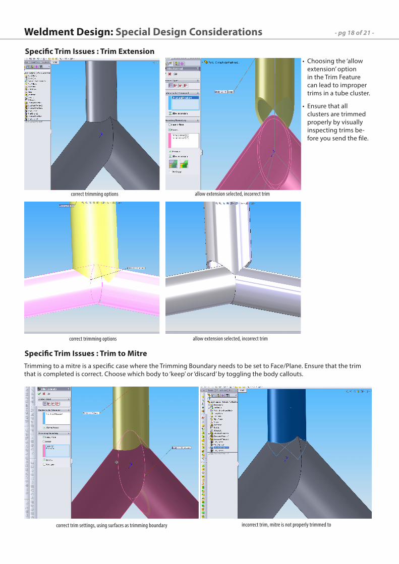
Specific Trim Issues : Trim Extension
correct trimming options allow extension selected, incorrect trim
Choosing the ‘allow •extension’ option in the Trim Feature can lead to improper trims in a tube cluster.
Ensure that all •clusters are trimmed properly by visually inspecting trims be-fore you send the file.
correct trimming options allow extension selected, incorrect trim
Specific Trim Issues : Trim to MitreTrimming to a mitre is a specific case where the Trimming Boundary needs to be set to Face/Plane. Ensure that the trim that is completed is correct. Choose which body to ‘keep’ or ‘discard’ by toggling the body callouts.
correct trim settings, using surfaces as trimming boundary incorrect trim, mitre is not properly trimmed to
- pg 19 of 21 -
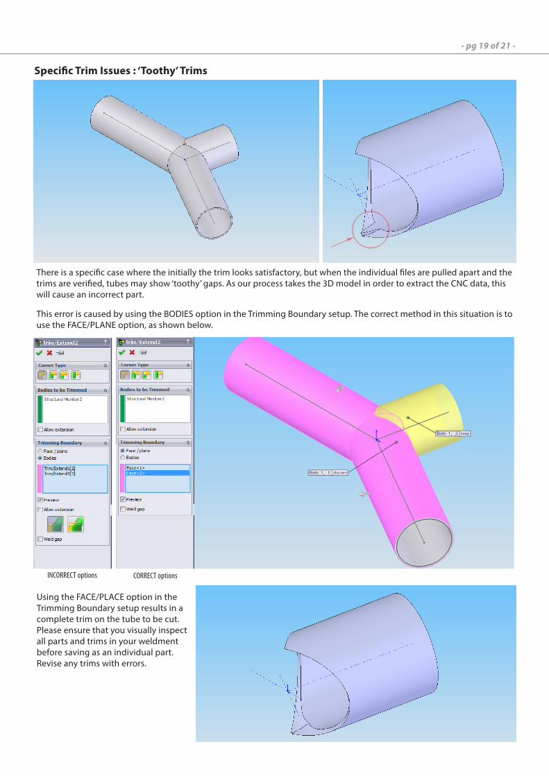
Specific Trim Issues : ‘Toothy’ Trims
INCORRECT options
Using the FACE/PLACE option in the Trimming Boundary setup results in a complete trim on the tube to be cut. Please ensure that you visually inspect all parts and trims in your weldment before saving as an individual part. Revise any trims with errors.
There is a specific case where the initially the trim looks satisfactory, but when the individual files are pulled apart and the trims are verified, tubes may show ‘toothy’ gaps. As our process takes the 3D model in order to extract the CNC data, this will cause an incorrect part.
This error is caused by using the BODIES option in the Trimming Boundary setup. The correct method in this situation is to use the FACE/PLANE option, as shown below.
CORRECT options
- pg 20 of 21 -
Most teams start their suspension node sketches and build their cars around their suspension. We recommend doing a side view of the car and determining the fit of the driver within the car. FSAE has made a model of what a 95 percentile male will look like and call this model “Percy”. The figure shows what Percy looks like according to a FSAE Workshop. We encourage putting “Percy” in your right side view of your FSAE chassis design to make sure spacing is correct.
From pg20 of FSAE Workshop 10.25.2008
Fully define the sketches when building the wireframe. Fully defined sketches helps with the stability of the model. Breaking the model down into several sketches is also very important. Some teams attempt to put all of the tubes in a single 3Dsketch and this makes it very difficult to adjust; it also makes SolidWorks less stable and makes design changes difficult to implement. We recommend doing a separate 3Dsketch for each of the bent tubes. Bent tubes must follow the “Bending Die Chart: Guidelines” Document. See the Bent tube section of this document for more details and examples.
SAE Student ProjectsCreating a Model
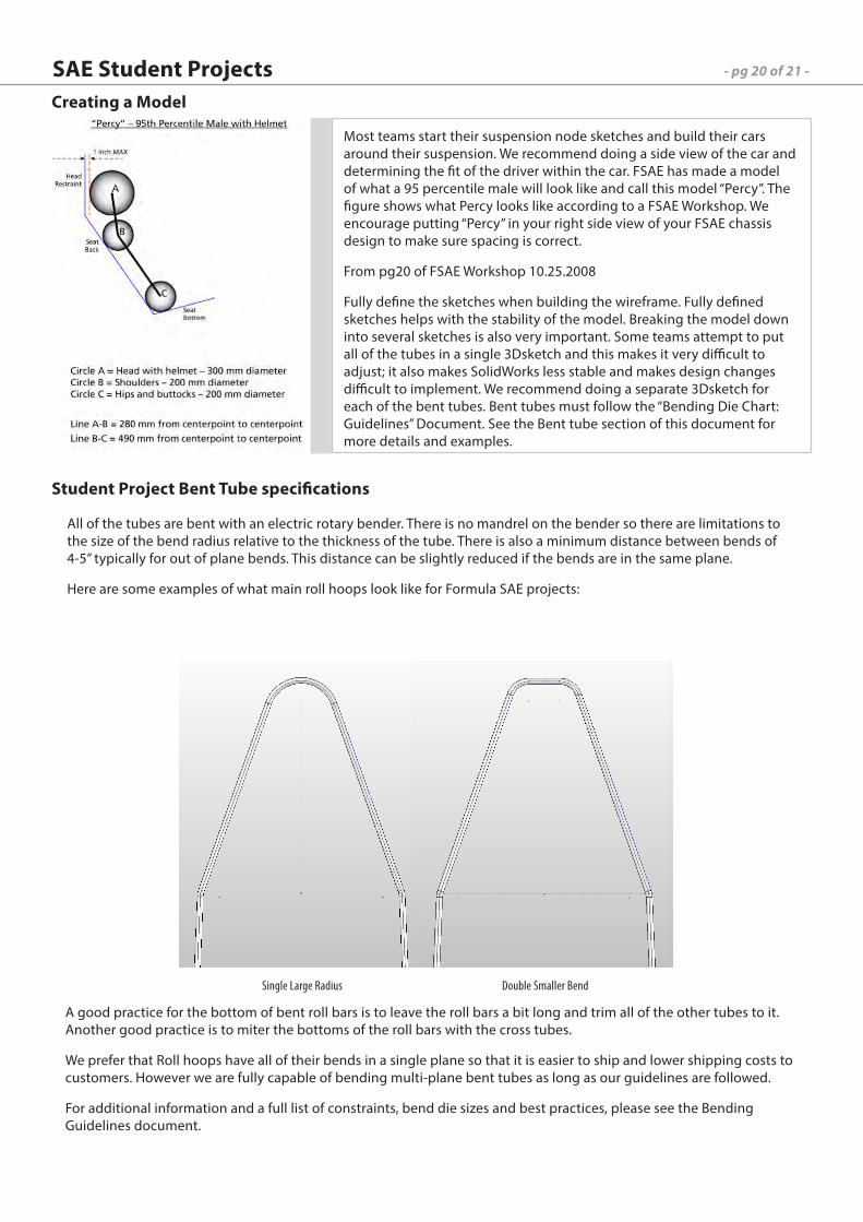
All of the tubes are bent with an electric rotary bender. There is no mandrel on the bender so there are limitations to the size of the bend radius relative to the thickness of the tube. There is also a minimum distance between bends of 4-5” typically for out of plane bends. This distance can be slightly reduced if the bends are in the same plane.
Here are some examples of what main roll hoops look like for Formula SAE projects:
A good practice for the bottom of bent roll bars is to leave the roll bars a bit long and trim all of the other tubes to it. Another good practice is to miter the bottoms of the roll bars with the cross tubes.
We prefer that Roll hoops have all of their bends in a single plane so that it is easier to ship and lower shipping costs to customers. However we are fully capable of bending multi-plane bent tubes as long as our guidelines are followed.
For additional information and a full list of constraints, bend die sizes and best practices, please see the Bending Guidelines document.
Single Large Radius Double Smaller Bend
Student Project Bent Tube specifications

VR3 Engineering Ltd.45 Dunlop Place,Stratford, ON CANADA+1 519 273 [email protected]

![1 $SU VW (G +LWDFKL +HDOWKFDUH %XVLQHVV 8QLW 1 X ñ 1 … · 2020. 5. 26. · 1 1 1 1 1 x 1 1 , x _ y ] 1 1 1 1 1 1 ¢ 1 1 1 1 1 1 1 1 1 1 1 1 1 1 1 1 1 1 1 1 1 1 1 1 1 1 1 1 1 1](https://img.pdfslide.us/doc/110x75/5fbfc0fcc822f24c4706936b/1-su-vw-g-lwdfkl-hdowkfduh-xvlqhvv-8qlw-1-x-1-2020-5-26-1-1-1-1-1-x.jpg)


![$1RYHO2SWLRQ &KDSWHU $ORN6KDUPD +HPDQJL6DQH … · 1 1 1 1 1 1 1 ¢1 1 1 1 1 ¢ 1 1 1 1 1 1 1w1¼1wv]1 1 1 1 1 1 1 1 1 1 1 1 1 ï1 ð1 1 1 1 1 3](https://img.pdfslide.us/doc/110x75/5f3ff1245bf7aa711f5af641/1ryho2swlrq-kdswhu-orn6kdupd-hpdqjl6dqh-1-1-1-1-1-1-1-1-1-1-1-1-1-1.jpg)


![[XLS] · Web view1 1 1 2 3 1 1 2 2 1 1 1 1 1 1 2 1 1 1 1 1 1 2 1 1 1 1 2 2 3 5 1 1 1 1 34 1 1 1 1 1 1 1 1 1 1 240 2 1 1 1 1 1 2 1 3 1 1 2 1 2 5 1 1 1 1 8 1 1 2 1 1 1 1 2 2 1 1 1 1](https://img.pdfslide.us/doc/110x75/5ad1d2817f8b9a05208bfb6d/xls-view1-1-1-2-3-1-1-2-2-1-1-1-1-1-1-2-1-1-1-1-1-1-2-1-1-1-1-2-2-3-5-1-1-1-1.jpg)


![089 ' # '6& *#0 & 7 · 2018. 4. 1. · 1 1 ¢ 1 1 1 ï1 1 1 1 ¢ ¢ð1 1 ¢ 1 1 1 1 1 1 1ýzð1]þð1 1 1 1 1w ï 1 1 1w ð1 1w1 1 1 1 1 1 1 1 1 1 ¢1 1 1 1û](https://img.pdfslide.us/doc/110x75/60a360fa754ba45f27452969/089-6-0-7-2018-4-1-1-1-1-1-1-1-1-1-1-1-1-1.jpg)


