Embed Size (px)
Citation preview
Sadhan aVol. 28, Parts 3 & 4,June/August 2003, pp. 359–382. © Printed in India
Solidification cracking in austenitic stainless steel welds
V SHANKAR, T P S GILL, S L MANNAN and S SUNDARESAN∗
Indira Gandhi Centre for Atomic Research, Kalpakkam 603 102, India∗Department of Metallurgical Engineering, Indian Institute of Technology –Madras, Chennai 600 036, Indiae-mail: [email protected]
Abstract. Solidification cracking is a significant problem during the weldingof austenitic stainless steels, particularly in fully austenitic and stabilized compo-sitions. Hot cracking in stainless steel welds is caused by low-melting eutecticscontaining impurities such as S, P and alloy elements such as Ti, Nb. The WRC-92 diagram can be used as a general guide to maintain a desirable solidificationmode during welding. Nitrogen has complex effects on weld-metal microstruc-ture and cracking. In stabilized stainless steels, Ti and Nb react with S, N and Cto form low-melting eutectics. Nitrogen picked up during welding significantlyenhances cracking, which is reduced by minimizing the ratio of Ti or Nb tothat of C and N present. The metallurgical propensity to solidification crack-ing is determined by elemental segregation, which manifests itself as a brittle-ness temperature range or BTR, that can be determined using the varestraint test.Total crack length (TCL), used extensively in hot cracking assessment, exhibitsgreater variability due to extraneous factors as compared to BTR. In austeniticstainless steels, segregation plays an overwhelming role in determining crackingsusceptibility.
Keywords. Austenitic stainless steels; solidification cracking; composition eff-ects; varestraint testing.
1. Introduction
Austenitic stainless steels, particularly those that contain no ferrite, are susceptible to hotcracking during welding. Hot cracking or hot tearing has been investigated in castings (Pellini1952) and welds (Medovar 1954) for several decades. Hot cracking refers to cracking thatoccurs during welding, casting or hot working at temperatures close to the melting point ofthe material. The cracking is known to occur both above the liquation temperature – knownas supersolidus cracking (Borland 1960) – and in the solid state, called subsolidus cracking.The various types of hot cracks encountered in stainless steel weldments have been classifiedby Hemsworthet al (1969). Supersolidus cracking may manifest as solidification cracking,occurring in the presence of a liquid phase in the fusion zone, or as liquation cracking in theheat-affected zone (HAZ) where it is accompanied by grain-boundary melting. Solidificationcracking in the weld metal is considered the most deleterious and is more widely observedthan the other types of cracking.
359

360 V Shankar et al
Although much research experience exists on the nature of hot cracking in stainless steelsand various measures required for minimising it, complete understanding of the phenomenonis still lacking. Further, new materials are continuously being developed for various appli-cations such as power systems, nuclear, chemical and petrochemical industries, driven byrequirements of higher operating temperatures and lifetimes (Maziasz 1989). The materialdesign criteria for these systems may vary from thermal stability, and resistance to enhancedcreep under irradiation and corrosion resistance in various media. Thus, these materials maynot be designed primarily to be weldable and there is a continuing need to solve weldingproblems in their fabrication.
Austenitic stainless steels of the AISI 300 series of stainless steels usually solidify duringwelding as a mixture of austenite and ferrite. The ferrite almost fully transforms to austen-ite on cooling, but there could be retention of a few percent ofδ-ferrite in the weld metal.The association ofδ-ferrite with cracking resistance in stainless steel welds is quite old.As early as 1938, Schereret al (1941) filed a patent, which claimed that crack-resistantweld deposits could be produced if the composition is adjusted to result in 5–35% fer-rite in the completed weld. Since then, the problem of cracking in the weld metal canbe considered as virtually eliminated in cases where ferrite can be retained in the weld.Nevertheless, solidification cracking continues to cause concern in fully austenitic stainlesssteels, when ferrite is restricted and when composition adjustments during welding are notpossible.
The addition of elements like phosphorus and boron can result in improved irradiationstability and creep properties (Maziasz 1989) and a minimum content of phosphorus isspecified on this account. However, impurity elements such as sulphur and phosphorus, andminor alloy elements such as boron, silicon, titanium and niobium promote hot cracking,particularly in fully austenitic steels (Hull 1960).
Nitrogen-added stainless steels exhibit several unique characteristics such as superiorstrength at ambient as well as high temperatures, excellent corrosion resistance in variousmedia and are candidate materials to replace other more expensive materials. Weldabilityof type 316LN steels has not been fully investigated and the service record of weldingconsumables is not currently established. Here, the major consideration is the role ofnitrogen in the base metal and consumables during welding. Nitrogen has been reportedto increase cracking in primary ferritic-solidifying compositions, but in fully austeniticsteels a beneficial effect is reported. Effects of nitrogen on microstructure and crackingbehaviour appear to be complex and the mechanisms thereof are not completely under-stood.
Development of reliable testing methods for reproducible quantitative information onhot cracking susceptibility has been continuing since the 1950s. The varestraint test (Sav-age & Lundin 1965) and its modifications have been used in a large number of studieson hot cracking susceptibility of materials. The varestraint tests provide several quanti-tative parameters that have been used for weldability comparisons and process and alloydevelopment (Lundinet al 1982). The compositional requirements for fabrication andservice properties may be in opposition, and optimal levels must be found for satisfac-tory weldability. Optimisation of composition based on weldability considerations wouldrequire standardised tests and assessment criteria to be evolved. The purpose of thisreview is to examine the current understanding of solidification cracking in austeniticstainless steels with particular emphasis on nitrogen-alloyed and stabilized stainlesssteels.

Solidification cracking in austenitic stainless steel welds 361
Figure 1. Liquidus and solidus projections of the Fe–Cr–Ni system shown along with the constituentbinaries (after Folkhard 1988).
2. Solidification-phase relationships in the Fe–Cr–Ni system
A study of the Fe–Cr–Ni phase diagram is required for an understanding of the solidificationbehaviour of stainless steel welds. The liquidus and solidus projections of the Fe–Cr–Nisystem along with the constituent binaries (Folkhard 1988) are shown in figure 1. The Fe–Crsystem is isomorphous down to temperatures well below the solidification range. The Cr–Ni system shows a eutectic at 1618K(1345◦ C) and 49wt.% nickel. In the Fe–Ni system,the δ-ferrite phase on the iron side forms a short peritectic loop, after which the system iscompletely soluble to 100wt.% nickel. Thus, in the Fe–Cr–Ni ternary system, the liquidusprojection starts at the peritectic reaction on the Fe–Ni system(δ +L ↔ γ ) and moves downto the eutectic reaction(L ↔ δ + γ ) on the Cr–Ni system. On the Ni- and Cr-enriched sidea ternary eutectic is formed at 1573K(1300◦C).
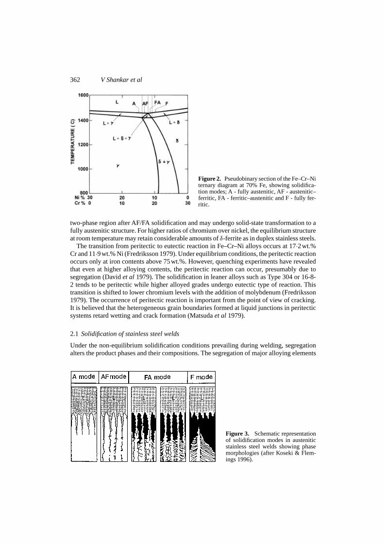
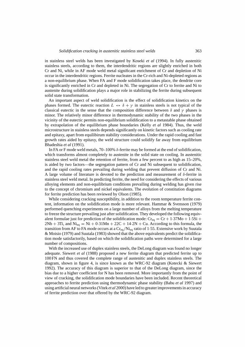
The initial solidifying phase is determined by the position of the alloy with respect to theliquidus surface, which under equilibrium conditions proceeds toward the eutectic/peritecticbefore solidification is complete. Most stainless steel compositions in wide use occur on theiron-rich side of the ternary between 50 and 70wt.% iron. The 70wt.% iron isopleth of theternary shown in figure 2 is commonly used to identify the primary solidifying phases orsolidification modes for various compositions. Four distinct modes are normally considered,viz., austenitic (A), austenitic–ferritic or primary austenitic (AF), ferritic-austenitic or primaryferritic (FA) and ferritic (F). The approximate composition ranges in which these modes occurare indicated in figure 2, while the microstructure and morphology of the phases during andafter solidification are shown schematically in figure 3. Alloys solidifying in the A modewill remain unchanged to low temperatures, while those solidifying as AF would form someeutectic ferrite. Compositions that solidify in the FA and F modes pass through theδ ↔ γ two-phase region and may re-enter the single-phase austenite field. This is due to the asymmetryof the two-phase field towards the primary ferritic side of the diagram, as seen in figure 2.Thus, alloys such as Type 304 and 316 that are fully austenitic at room temperature enter this
362 V Shankar et al
Figure 2. Pseudobinary section of the Fe–Cr–Niternary diagram at 70% Fe, showing solidifica-tion modes; A - fully austenitic, AF - austenitic–ferritic, FA - ferritic–austenitic and F - fully fer-ritic.
two-phase region after AF/FA solidification and may undergo solid-state transformation to afully austenitic structure. For higher ratios of chromium over nickel, the equilibrium structureat room temperature may retain considerable amounts ofδ-ferrite as in duplex stainless steels.
The transition from peritectic to eutectic reaction in Fe–Cr–Ni alloys occurs at 17·2wt.%Cr and 11·9wt.% Ni (Fredriksson 1979). Under equilibrium conditions, the peritectic reactionoccurs only at iron contents above 75wt.%. However, quenching experiments have revealedthat even at higher alloying contents, the peritectic reaction can occur, presumably due tosegregation (Davidet al 1979). The solidification in leaner alloys such as Type 304 or 16-8-2 tends to be peritectic while higher alloyed grades undergo eutectic type of reaction. Thistransition is shifted to lower chromium levels with the addition of molybdenum (Fredriksson1979). The occurrence of peritectic reaction is important from the point of view of cracking.It is believed that the heterogeneous grain boundaries formed at liquid junctions in peritecticsystems retard wetting and crack formation (Matsudaet al1979).
2.1 Solidification of stainless steel welds
Under the non-equilibrium solidification conditions prevailing during welding, segregationalters the product phases and their compositions. The segregation of major alloying elements
Figure 3. Schematic representationof solidification modes in austeniticstainless steel welds showing phasemorphologies (after Koseki & Flem-ings 1996).
Solidification cracking in austenitic stainless steel welds 363
in stainless steel welds has been investigated by Kosekiet al (1994). In fully austeniticstainless steels, according to them, the interdendritic regions are slightly enriched in bothCr and Ni, while in AF mode weld metal significant enrichment of Cr and depletion of Nioccur in the interdendritic regions. Ferrite nucleates in the Cr-rich and Ni-depleted regions asa non-equilibrium phase. When FA and F mode solidification takes place, the dendrite coreis significantly enriched in Cr and depleted in Ni. The segregation of Cr to ferrite and Ni toaustenite during solidification plays a major role in stabilizing the ferrite during subsequentsolid state transformation.
An important aspect of weld solidification is the effect of solidification kinetics on thephases formed. The eutectic reactionL ↔ δ + γ in stainless steels is not typical of theclassical eutectic in the sense that the composition difference betweenδ andγ phases isminor. The relatively minor difference in thermodynamic stability of the two phases in thevicinity of the eutectic permits non-equilibrium solidification to a metastable phase obtainedby extrapolation of the equilibrium phase boundaries (Kellyet al 1984). Thus, the weldmicrostructure in stainless steels depends significantly on kinetic factors such as cooling rateand epitaxy, apart from equilibirum stability considerations. Under the rapid cooling and fastgrowth rates aided by epitaxy, the weld structure could solidify far away from equilibriumBhadeshiaet al (1991).
In FA or F mode weld metals, 70–100%δ-ferrite may be formed at the end of solidification,which transforms almost completely to austenite in the solid state on cooling. In austeniticstainless steel weld metal the retention of ferrite, from a few percent to as high as 15–20%,is aided by two factors—the segregation pattern of Cr and Ni subsequent to solidification,and the rapid cooling rates prevailing during welding that prevent diffusion of Cr and Ni.A large volume of literature is devoted to the prediction and measurement ofδ-ferrite instainless steel weld metal. In predicting ferrite, the need for considering the effects of variousalloying elements and non-equilibrium conditions prevailing during welding has given riseto the concept of chromium and nickel equivalents. The evolution of constitution diagramsfor ferrite prediction has been reviewed by Olson (1985).
While considering cracking susceptibility, in addition to the room temperature ferrite con-tent, information on the solidification mode is more relevant. Hammar & Svensson (1979)performed quenching experiments on a large number of alloys from the melting temperatureto freeze the structure prevailing just after solidification. They developed the following equiv-alent formulae just for prediction of the solidification mode: Creq = Cr+ 1·37Mo+ 1·5Si+2Nb+ 3Ti, and Nieq = Ni + 0·31Mn+ 22C+ 14·2N + Cu.According to this formula, thetransition from AF to FA mode occurs at a Creq/Nieq ratio of 1·55. Extensive work by Suutala& Moisio (1979) and Suutala (1983) showed that the above equivalents predict the solidifica-tion mode satisfactorily, based on which the solidification paths were determined for a largenumber of compositions.
With the increased use of duplex stainless steels, the DeLong diagram was found no longeradequate. Siewertet al (1988) proposed a new ferrite diagram that predicted ferrite up to100FN and thus covered the complete range of austenitic and duplex stainless steels. Thediagram, shown in figure 4, is since known as the WRC-92 diagram (Kotecki & Siewert1992). The accuracy of this diagram is superior to that of the DeLong diagram, since thebias due to a higher coefficient for N has been removed. More importantly from the point ofview of cracking, the solidification mode boundaries have been included. Recent theoreticalapproaches to ferrite prediction using thermodynamic phase stability (Babuet al 1997) andusing artificial neural networks (Viteket al2000) have led to greater improvements in accuracyof ferrite prediction over that offered by the WRC-92 diagram.

364 V Shankar et al
Figure 4. The WRC-92 constitution diagram for weld metal ferrite, including solidification modeboundaries.
2.2 The relationship between solidification mode and room-temperature microstructure: Theferrite–austenite transformation
The interpretation and analysis of weld microstructures in austenitic stainless steels is com-plicated by the superposition of the solid state transformation from ferrite to austenite overthe as-solidified structure. The various ferrite morphologies observed at room temperaturecan be interpreted often only in terms of both the solidification mode and the subsequentsolid state transformation. It is convenient to consider the change in composition in terms ofCreq/Nieq ratio. For low ratios, A-mode solidification occurs and there is no change in struc-ture after solidification as no ferrite is present. For higher Creq/Nieq, AF mode solidificationoccurs in which austenite is the primary phase and a part of the remaining liquid solidifies asintercellular ferrite. For higher Creq/Nieq ratios during FA and F mode solidification, the hightemperature microstructure has been shown to contain 70–100% ferrite (Thier 1987). On cool-ing to lower temperatures, most of the ferrite transforms and the residual ferrite left behindin the Cr-rich dendritic cores gives rise to the characteristic structure known as vermicularferrite. Vermicular ferrite has been shown to result from a diffusional transformation at fairlyhigh temperatures (1373–1573K) under normal arc welding conditions (Davidet al 1979).For still higher Creq/Nieq ratios in the FA and F modes, the ferrite is increasingly stable andtheδ → δ + γ phase boundary occurs lower in temperature. At these lower transformationtemperatures, an orientation relationship between the parent and product phases is favoured.As the transformation kinetics become sluggish, elongated acicular and Widmanstätten typemorphologies are promoted.
3. The theory of hot cracking
Solidification cracking occurs predominantly by the segregation of solutes to form low-melting phases, which under the action of shrinkage stresses accompanying solidificationcause cracking. Several theories have been advanced to explain the phenomenon (Pellini

Solidification cracking in austenitic stainless steel welds 365
Figure 5. Effect of constitutional features on crack-ing susceptibility in binary systems according to thegeneralized theory of Borland (1960).
1952; Medovar 1954; Borland 1960; Holt 1992). The initial theories (Medovar 1954) tookinto account the fact that cracking is associated with segregation; the wider the liquid–solidrange of the alloy, the greater the susceptibility. However, this theory was not entirely satis-factory, as several exceptions could be found and the freezing range appeared to be only oneof many factors influencing cracking. The ‘Generalised Theory’ of cracking was proposed byBorland (1960). According to Borland, solidification involves four stages that are classifiedaccording to the distribution of the liquid and solid phases, as shown in figure 5 for a binaryalloy. In stage 1, the solid phase is dispersed, the liquid phase is continuous and both the phasescan accommodate relative movement. In stage 2, both liquid and solid phases are continuous,but the solid dendrites are interlocked and only the liquid is capable of movement. At thisstage, the liquid can heal any cracks formed. In stage 3, the solid crystals are in an advancedstage of development and the free passage of liquid is prevented. The liquid is present in verysmall quantity. At this stage, if a stress is applied which exceeds the tolerance of the material,cracking can occur, which cannot be filled by the remaining liquid phase. This stage, duringwhich much of the cracking occurs, is called the critical solidification range (CSR). In stage 4,solidification is complete and no cracking involving the liquid phase is possible.
Borland stated that for high cracking susceptibility, in addition to a wide freezing range,the liquid must also be distributed in a way that allows high stresses to be built up betweengrains. The extreme cases in which liquid can be distributed are as films or as isolated droplets,the actual behaviour depending on the interfacial energies of the solid and liquid phases. Theangle of wetting of the solid interfaces by the liquid is related to the interfacial energies asfollows (Smith 1948):
γSL/γSS = 1/(2 cosθ/2) = τ,
whereγSL andγSS are the energies of the solid–liquid interface and the solid–solid grainboundary respectively andθ is the dihedral wetting angle, which varies between 0 and 180.Figure 6 shows the variation ofθ with increasing interfacial energy ratioτ .
Wetting of the grain boundaries by a continuous liquid film occurs forτ less than 0·5(θ <
60) and for values above 0·5, the resistance to cracking increases. The higher the solid–liquidsurface energy, the greater is the tendency to minimise the liquid–solid interface by formationof isolated pockets of liquid instead of continuous films. Borland showed that the interfacialenergy ratio for iron–iron sulphide films was close to 0·5, explaining the deleterious effect

366 V Shankar et al
Figure 6. The variation of dihedral contact angle between liquid and solid phases with surface energyratio; the change in grain wetting behaviour with decreasing wetting angle is also illustrated.
of sulphur in steels. The theory revealed the importance of wetting in relation to cracking.However, Borland’s theory suffers from a few practical difficulties as listed below: (a) thenon-equilibrium nature of the segregation would maximise the freezing range for even verydilute alloys, which the theory does not take into account (Clyne & Davies 1981), and (b) theeffect of wetting angle of the liquid and solid phases on cracking is very difficult to quantify.
According to the generalised theory, hot cracks are believed to initiate during the laterstages of solidification when most of the liquid has solidified. Some experimental observa-tions (Matsudaet al1982b; Semenyuket al1986) have shown, however, that hot cracks caninitiate at temperatures very close to the liquidus and at much smaller fractions of solid thanpreviously believed(fS ≈ 0·15). In a recent review, Matsuda (1990) has suggested that crackinitiation and propagation must be considered separately, and proposed a modification toBorland’s theory. According to the modified theory, the critical solidification range (stage 3)starts at a higher temperature (closer to the liquidus) and is divided into two stages (figure 7),an initiation stage (stage 3(h)) where cracks can initiate and a propagation stage (stage 3(l))where an already-existing crack grows. Many investigators believe (Borland 1960; Prokhorov& Prokhorov 1971) that there exists a temperature range during solidification over which
Figure 7. Modified concept of the effect of con-stitution on cracking susceptibility in binary systems(Matsuda 1990).

Solidification cracking in austenitic stainless steel welds 367
a material remains prone to brittleness that is measurable experimentally. The idea is that,irrespective of the stress field experienced during welding, the temperature range of suscep-tibility known as the brittle temperature range or BTR, can be considered a function of thecomposition.
Matsudaet al (1989a, b) have shown that the BTR can be obtained by calculation of liq-uid composition applying the Schiel equation and using suitable numerical techniques forcomputation. Hot cracking test methods that enable measurement of the brittleness tempera-ture range (BTR) are therefore very useful in predicting cracking in actual situations. This isdiscussed further in a subsequent section.
4. Solidification cracking in austenitic stainless steel welds
4.1 Forms of solidification cracking
Solidification cracking is observed as (a) gross cracking, occurring at the junctions of den-drites with differing orientations, detectable by visual and liquid penetrant testing, and (b)microfissuring in the interdendritic regions which are revealed only by application of strainto the cracked region or at high magnifications. The increase in cracking that occurs whenthe solidification range is widened by the formation of low-melting eutectics with impurityelements was identified by early investigators and various theories of hot cracking were devel-oped, as already discussed. Composition affects the tendency of stainless steel weld metaltowards cracking in two major ways. First, as discussed earlier, the primary mode of solidifi-cation from the liquid is a function of composition and FA/F mode of solidification has beenfound to be beneficial in reducing cracking. Solidification mode determines the nature of thesolid interfaces present during solidification. The second effect of composition is throughsegregation, which determines the wetting characteristics and constitutional supercooling inthe interdendritic regions. The effects of solidification mode and composition on hot crackingwill be discussed in detail in subsequent sections.
The heat input during welding also affects the hot cracking behaviour significantly, primar-ily by affecting the amount and scale of segregation. Goodwin (1988) using the Sigmajig testto evaluate GTAW, laser and electron beam welds found that increased heat inputs decreasedthe threshold stress for cracking, thereby increasing cracking susceptibility. Higher energydensities decreased cracking, and cracking resistance was progressively higher for GTAW,electron and laser beam welding, in the order of decreasing heat inputs. However, in arc weld-ing of stainless steels where solidification rates do not vary over a wide range, differences incracking attributable to welding parameter variations may not be significant.
4.2 Effect ofδ-ferrite and solidification mode on solidification cracking
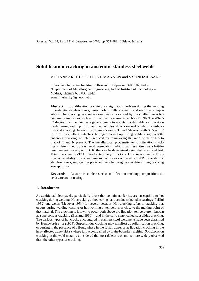
The effect of varyingδ-ferrite contents on cracking in stainless steels was studied by Hull(1967) using the cast pin tear test. Hull found that, while the cracking susceptibility washigh for fully austenitic compositions, specimens with 5–30% ferrite were quite resistantto cracking. When ferrite content increased further, the cracking sensitivity again increased.Masumotoet al (1972) found that it was the FA/F solidification mode that was essential toreducing cracking rather than residual ferrite content after welding. Subsequently, variousinvestigations were conducted using hot cracking tests for different commercially used com-positions. Kujanpaaet al (1979) represented cracking data from the literature on a map ofP+ S vs. Creq/Nieq ratio. They used the Schaeffler equivalent formulae for Cr and Ni to cal-culate the ratio. On this map, they plotted cracking data from a number of studies, including

368 V Shankar et al
Figure 8. Solidification cracking behaviour in austenitic stainless steel welds as a function of Scha-effler Creq/Nieq ratio and P+S levels (after Kujanpaaet al1979).
their own, as shown in figure 8. They found that highly susceptible compositions lay boundedby a curve with a lower limit of 0·01–0·015wt.% P+S, and limited on the Creq/Nieq axis by avalue of 1·5, up to which a primary austenitic solidification mode exists. Thus, compositionswith Creq/Nieq greater than 1·5 or with P+ S < 0·01 wt% were ‘not susceptible’. In effect,the diagram divided the compositions according to hot cracking susceptibility. However, thecracking propensity abruptly increased when the Creq/Nieq ratio was below 1·5, unless theP+ S content was below 0·01wt%.
Lundinet al(1988c) modified this diagram to represent longitudinal varestraint test data on3mm thick specimens, which is shown in figure 9. The equivalent formulae used to calculateCreq/Nieq ratio were changed to that of Hammar & Svensson (1979). Lundin classified thecompositions on the basis of total crack length (TCL) in the varestraint test at 4% strain,
Figure 9. Solidification crack-ing behaviour in austenitic stain-less steel welds as a functionof Hammar–Svensson Creq/Nieqratio and P+S levels (Lundinet al1988).
Solidification cracking in austenitic stainless steel welds 369
as ‘highly susceptible’ for TCL> 2·5mm, ‘susceptible’ for TCL between 1·5–2·5mm, and‘not susceptible’ for TCL< 1·5mm. When the data were plotted on this diagram, the mixedsolidification mode FA region, in which Creq/Nieq ratio is 1·5–1·6, was identified as having acracking susceptibility intermediate between that of the A-mode and FA or F-mode materials.In this region, cracking was sensitive to P+S levels.The FA/F-mode materials with a Creq/Nieq
above 1·6 were quite tolerant to impurity elements even over 0·04wt.%, while in A-modematerials(Creq/Nieq < 1.5), cracking is high for P+ S greater than about 0·015wt.%.
A number of factors have been proposed to explain the beneficial effects ofδ-ferrite oncracking behaviour:
(1) The higher solubility for impurity elements inδ-ferrite leads to less interdendritic seg-regation and reduces cracking tendency (Borland & Younger 1960).
(2) Cracks are arrested by the irregular path offered by a duplex austenite–ferrite structure.The peritectic/eutectic reaction interface arrests remaining pockets of liquid and thuscrack propagation (Matsuda 1979).
(3) The lower surface energy of theγ –δ boundary and its reduced wettability by eutecticfilms compared toγ –γ or δ–δ interfaces is an important factor (Hull 1967).
(4) The presence of ferrite results in a larger interface area due to the solid state transforma-tion to austenite that begins soon after solidification. The increased area disperses theconcentration of impurity elements at the grain boundaries.
(5) The ductility of ferrite at high temperatures is greater than that of austenite, allowingrelaxation of thermal stresses.
(6) The lower thermal expansion coefficient of ferrite as compared to austenite results inless contraction stresses and fissuring tendency.
(7) The solidification temperature range of primary ferrite welds is less than that of pri-mary austenite solidified welds, providing a smaller critical temperature range for crackformation (Pellini 1952).
(8) The presence of ferrite refines the grain size of the solidified metal, which results inbetter mechanical properties and cracking resistance.
(9) The higher coefficients for impurity diffusion in ferrite as compared with austenite allowfaster homogenisation in ferrite and less tendency for cracking.
(10) Coarse grain formation in the HAZ occurring by recrystallisation and grain growthin fully austenitic metals increases susceptibility to liquation cracking (Kujanpaaet al1987), while ferrite forming compositions are not susceptible.
(11) The volume contraction associated with the ferrite-austenite transformation reducestensile stresses close to the crack tip, which decreases cracking tendency (Thieret al1987).
Brookset al (1991) argue that since solidification cracking is associated mainly with grainboundaries, those factors that affect the nature of the grain boundaries should be more relevantto cracking behaviour. From this standpoint, a review of the literature suggests that the majorfactors that make FA/F mode weld metals resistant can be listed as, (a) the higher solubility ofS, P etc., in the ferrite that introduces less of the harmful solute in the interdendritic regions,(b) lower wettability of grain boundaries in a duplex structure and (c) grain refinement duringFA mode solidification. Hence the factors 1–4 and 8 listed above can be considered of majorimportance. Factors 5 and 6 relating to ductility and thermal expansion of ferrite appear lesslikely, since cracking is higher for the F-mode in relation to FA mode weld metals (Matsudaet al 1986, 1989b). The other factors may have a relatively minor but contributory role to
370 V Shankar et al
play. However, it must be mentioned that the mechanics of the cracking process is still notcompletely understood.
4.3 Effects of impurity and alloy elements on cracking
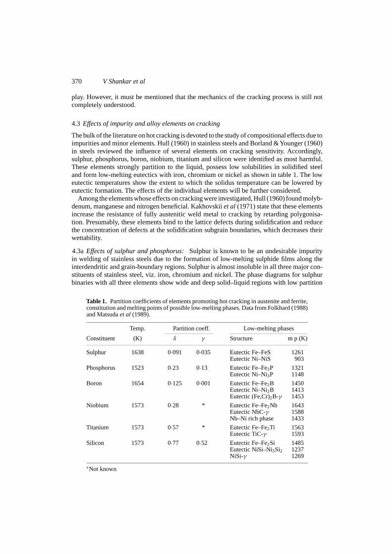
The bulk of the literature on hot cracking is devoted to the study of compositional effects due toimpurities and minor elements. Hull (1960) in stainless steels and Borland &Younger (1960)in steels reviewed the influence of several elements on cracking sensitivity. Accordingly,sulphur, phosphorus, boron, niobium, titanium and silicon were identified as most harmful.These elements strongly partition to the liquid, possess low solubilities in solidified steeland form low-melting eutectics with iron, chromium or nickel as shown in table 1. The loweutectic temperatures show the extent to which the solidus temperature can be lowered byeutectic formation. The effects of the individual elements will be further considered.
Among the elements whose effects on cracking were investigated, Hull (1960) found molyb-denum, manganese and nitrogen beneficial. Kakhovskiiet al (1971) state that these elementsincrease the resistance of fully austenitic weld metal to cracking by retarding polygonisa-tion. Presumably, these elements bind to the lattice defects during solidification and reducethe concentration of defects at the solidification subgrain boundaries, which decreases theirwettability.
4.3aEffects of sulphur and phosphorus:Sulphur is known to be an undesirable impurityin welding of stainless steels due to the formation of low-melting sulphide films along theinterdendritic and grain-boundary regions. Sulphur is almost insoluble in all three major con-stituents of stainless steel, viz. iron, chromium and nickel. The phase diagrams for sulphurbinaries with all three elements show wide and deep solid–liquid regions with low partition
Table 1. Partition coefficients of elements promoting hot cracking in austenite and ferrite,constitution and melting points of possible low-melting phases. Data from Folkhard (1988)and Matsudaet al (1989).
Temp. Partition coeff. Low-melting phases
Constituent (K) δ γ Structure m p (K)
Sulphur 1638 0·091 0·035 Eutectic Fe–FeS 1261Eutectic Ni–NiS 903
Phosphorus 1523 0·23 0·13 Eutectic Fe–Fe3P 1321Eutectic Ni–Ni3P 1148
Boron 1654 0·125 0·001 Eutectic Fe–Fe2B 1450Eutectic Ni–Ni2B 1413Eutectic (Fe,Cr)2B-γ 1453
Niobium 1573 0·28 * Eutectic Fe–Fe2Nb 1643Eutectic NbC-γ 1588Nb–Ni rich phase 1433
Titanium 1573 0·57 * Eutectic Fe–Fe2Ti 1563Eutectic TiC-γ 1593
Silicon 1573 0·77 0·52 Eutectic Fe–Fe2Si 1485Eutectic NiSi–Ni3Si2 1237NiSi-γ 1269
∗Not known

Solidification cracking in austenitic stainless steel welds 371
coefficients for sulphur in austenite. Sulphur is strongly rejected into the liquid during solid-ification of austenite, rapidly lowering the melting point of the interdendritic liquid. Thus,the potential for forming low-melting eutectics remains strong even with very low contentsin austenite(< 0·005 wt.%)(Matsuda 1981). On the other hand,δ-ferrite shows higher sol-ubility for elements like S, P, Si and Nb.
Solidification in the FA mode is known to increase tolerance for S content to as highas 0·05wt.% without hot cracking. Lundinet al (1988a) investigated weldability of free-machining stainless steels, and found that, provided a ferritic solidification mode is main-tained, steels with sulphur contents of up to 0·35wt.% could show satisfactory weldability.However, in the case of type 310 steel solidifying in the austenitic mode, sulphide filmswere present even with 0·005wt.% S and increased the brittleness temperature range alongwith phosphorus. Matsudaet al (1981) recommended that for fully austenitic stainless steels,the maximum S and P contents are 0·005 and 0·006wt.% respectively, to avoid fusion zonecracking. In a study of heat-affected zone cracking in a titanium-containing 15Cr–15Ni steel,Persson (1971) and Egnell & May (1970) found grain-boundary precipitates of titanium car-bosulphide or titanium sulphide which decreased the hot ductility in the temperature range1373–1573K. Kujanpaaet al (1987) found sulphur enrichment of 2000 times at HAZ cracksin type 310 stainless steel. Thus, the harmful role of sulphur in hot cracking is evident.
Phosphorus ranks next to sulphur in the list of elements detrimental to good weldabilityin stainless steels. Like sulphur, P forms low-melting eutectics with iron, chromium andnickel. The maximum solubility of P in austenite at the eutectic point (1423K) with ironis 0·25wt.% and that in ferrite is 2·8wt.% at 1323K. Phosphide eutectics at interdendriticregions have been found to extend the brittleness temperature range in varestraint testing to asmuch as 250K lower than the solidus in fully austenitic type 310 steel (Matsudaet al1981).The segregation tendency remains high due to the wide solid–liquid range and low eutectictemperatures (1373K). Brooks (1974) identifies phosphorus as particularly harmful in fullyaustenitic stainless steels since it has a strong tendency to spread as liquid films. Further, ithas been stated that the low diffusivity of P in both austenite and ferrite phases even at hightemperatures virtually precludes homogenisation (Folkhard 1988).
The harmful effects of S and P have led to work on addition of other elements that counteracttheir effects. Manganese additions are well-known to decrease cracking in high-S steels byforming higher-melting MnS-γeutectics in preference to FeS (Hull 1960; Dixon 1988).Further, the addition of lanthanum and other rare-earths has been found highly effective inbinding the P and S as stable compounds (Matsudaet al1982a).
4.3b Nitrogen in austenitic stainless steel welds:In 316LN stainless steel for nuclear ser-vice, carbon has been reduced to decrease the propensity for intergranular corrosion. Nitrogenis added mainly to recover the higher strength and elevated temperature properties associatedwith the loss of carbon in comparison with conventional 316 (Eckenrod & Kovach 1979).Nitrogen has potent effects on the microstructure and hence is expected to have strong influ-ence on hot cracking behaviour also. The influence of nitrogen on hot cracking of austeniticstainless steel weld metal has been reviewed by Menon & Kotecki (1989). Nitrogen in weldmetal arises from various sources such as prior content in the base metal, intentional additionthrough the shielding gas or as inadvertent pickup due to inadequate shielding during welding.
Nitrogen resides in weld metal in the following forms (Stevens 1989): (i) interstitial nitrogendissolved in the lattice structure – may collect around lattice defects, (ii) combined nitrogenpresent as nitrides, and (iii) occluded nitrogen in pores. It is the first two forms of nitrogenthat affect the metallurgical behaviour of the weld metal. According to Eckenrod & Kovach

372 V Shankar et al
(1979), 18-8 type stainless steels with nitrogen up to 0·16wt.% N show very good weldabilitywith no porosity or loss of nitrogen. However, with increased nitrogen to 0·24wt.%, pinholesand porosity due to nitrogen evolution are observed.
Nitrogen has a strong stabilising effect on austenite when present in iron and Fe–N austeniteis isomorphous with Fe–C austenite in the Fe–C–N system. The solubility of nitrogen inaustenite is enhanced by several solutes such as Cr, Mn and to a greater extent by V andNb. Mo increases solubility slightly while C, Si and Ni tend to decrease it (Pehlke & Elliott1960). However, in commercial compositions containing several elements in combination,synergistic effects are present that make prediction of actual nitrogen pickup in weld metaldifficult. The nitrogen activity in steel decreases when elements with high N-affinity such asAl, Cr, V, or Nb are added, while it increases with additions of C, Ni, P, S or Si (Stevens 1989).
During GTA welding, it has been shown that the weld nitrogen content does not followSievert’s Law but is proportional to the nitrogen partial pressure in the shielding gas (Blake1979). When welding with pure argon, a nitrogen pickup of 0·02–0·03wt.% usually occurs,which is believed to result from imperfect shielding from the atmosphere. By deliberateaddition of up to 20vol.% nitrogen through the shielding gas, a maximum pickup of about0·25wt.% N has been reported in 304 and 316 type stainless steels (Arataet al1974; Ogawa &Tsunetomi 1982; Lundinet al1988a; Mudaliet al1986). The variation in N pickup reportedin different studies for similar shielding gas compositions appears to be related to two factors,namely variations in composition of the weld metal and the oxygen content in the shieldingatmosphere, both of which have major influence. Under identical conditions, Mudaliet al(1986) reported that type 304 picks up more N than 316 for the same partial pressure ofnitrogen, as shown in figure 10.
4.3c Effects of nitrogen on solidification cracking:In FA mode compositions, the most directeffect of nitrogen on cracking is through a decrease in weld metal ferrite content. Nitrogen, bystabilising the austenite phase, decreases the occurrence of primaryδ-ferrite, which results inreduced resistance to cracking. Several studies that focused on the possible role of nitrogenin influencing hot cracking behaviour (Arataet al 1974; Cieslaket al 1982; Matsudaet al1983a; Ogawaet al 1984) point to the fact that nitrogen changes the solidification modefrom ferritic to austenitic, thus increasing the cracking. Matsudaet al (1983a) investigatedcracking in type 304 weld metal with nitrogen addition. They concluded that nitrogen addition
Figure 10. Nitrogen content obtainedin weld metal as a function of nitrogencontent in argon shielding gas for type 304and 316 weld metals (data of Mudaliet al1986).
Solidification cracking in austenitic stainless steel welds 373
decreases the amount of primary ferrite, which also reduces the residual ferrite content.Their investigations also found increasing amounts of phosphides and sulphides at the grainboundaries with nitrogen addition, which promotes cracking. The cracking is characterisedby the brittleness temperature range (BTR), which increases with nitrogen content to reachvalues similar to that of fully austenitic type 310. On the other hand, Lundinet al(1980) did notfind any detrimental effect in their study on 316 weld metal with increasing nitrogen content,presumably because of the low impurity levels in the material. Zhitnikov (1981) reportedthat if the ferrite content is kept constant, increase in the nitrogen level is not detrimental tohot cracking resistance and may even have a slight beneficial effect. However, informationon the levels of P and S in their materials is not available. In summary, it appears that theeffect of nitrogen in weld metal containing ferrite (or ferritic solidification mode) is relatedto the levels of impurity elements. Hence nitrogen is probably detrimental in high-impurityweld metal(> 0·04 wt.%), but may have a neutral or beneficial effect in relatively purecompositions.
In fully austenitic stainless steels, the effects of nitrogen on cracking have been investi-gated by several workers (Kakhovskiiet al 1971; Arataet al 1974; Zhitnikovet al 1981;Ogawa & Tsunetomi 1982; Matsudaet al1983a; Lundinet al1988a). However, the findingsare controversial and indicate the complex effect of nitrogen on weld metal solidification.Kakhovskii (1971) and Zhitnikov (1981) reported beneficial effects of nitrogen addition ofup to 0·2wt.% in 18Cr–14Ni type steel. Similar results were reported by Ogawa & Tsunetomi(1982) in type 310 stainless steel and for 316L by Lundinet al(1988c). The beneficial effectsof nitrogen in these cases have been attributed to the retardation of polygonisation (Zhitnikov1981) and to a refinement in the dendritic structure (Lundinet al1988c). On the other hand,Arataet al(1974) found no significant effect of nitrogen contents up to 0·16wt.% on crackingin type 310. Further, Brooks (1975) reported a detrimental effect of high nitrogen contents(> 0·4 wt.%) on cracking in high-manganese 21-6-9 welds, probably by the formation of anitrogen-rich M6X type of eutectic. M6X-type phases along with Cr2N and Fe4N have alsobeen found in 17·5Cr–13Ni–2·8Mo weld metal with 0·13 to 0·24wt.% N (Omsen & Eliasson1971). However, no subsequent study has confirmed the existence of these phases. There isno strong evidence that N may either segregate strongly during solidification or form low-melting eutectics unlike C, which is known to form various carbide-based eutectics. Further,there has been no attempt to associate the effect of nitrogen and cracking with the levels ofimpurity elements. In recent work (Shankar 2000), N additions enhanced cracking in fullyaustenitic 316L weld metal with high S (0·012%) but did not increase cracking in low-S(0·001%) weld metal. The P levels in these steels are 0·035% and 0·031% respectively. Itwas concluded in this study that at high S levels, N acts synergistically with S to increasecracking.
In summary, it appears that nitrogen has diverse effects on the microstructure with corre-sponding consequences on the cracking behaviour of type 316 stainless steel.
(a) In FA mode alloys, a reduction in ferrite content and increase in segregation, leading toan increase in cracking.
(b) In A-mode alloys, retardation of polygonisation, which decreases wettability and hencecracking.
(c) In fully austenitic alloys, a refining effect on the solidification structure leading to adecrease in the cracking at moderate levels (up to 0·16wt.%).
(d) N appears to act synergistically with S to increase cracking in fully austenitic 316L weldmetal; low-S weld metal shows no effect on increasing N levels.

374 V Shankar et al
4.3d Effects of titanium and niobium on cracking in stabilized stainless steels:Austeniticstainless steels stabilized with titanium or niobium such as types 321 and 347 are known toexhibit higher susceptibility to hot cracking than the unstabilized varieties. Both these ele-ments stabilise ferrite and restrict the austenite phase field (Massalski 1996). Lundinet al(1975) found that, all other residual levels being equal, the presence of niobium alone con-tributed to increasing fissuring in type 347 weld metal and a ferrite number of 6 was requiredto completely eliminate fissuring. Arataet al (1974) found good weldability for type 321 and347 steels only with high ferrite contents (6 FN or greater). Hence the problem of crackingis severe in such steels when the ferrite level is low, for instance, when ferrite is not desirableduring service. In a study on the effects of various elements on cracking of fully austenitictype 347 stainless steel, Hoerl & Moore (1957) derived a statistical relation between com-position and cracking using the segmented circular groove test. They found that increasingC and Mn has strong positive effects in decreasing cracking, while phosphorus, sulphur andsilicon enhance cracking.
Phases responsible for cracking in stabilized stainless steels have been identified by severalinvestigators. In alloy 800,Wolstenholme (1973) found that a eutectic of the type (Ti,Nb)C-γ isresponsible for cracking, which was also confirmed by Lippold (1983). Matsudaet al(1983b)found that Ti addition up to 0·05wt.% decreases the hot cracking tendency by increasingthe melting point of low-melting phosphide eutectics. However, higher amounts to 0·6wt.%increases the BTR during varestraint testing by up to 100K. They found enrichment of Palong with Ti in the low-melting constituents. Recent work by Shankaret al (2000) foundtitanium carbosulphides, carbonitride and carbide in solidification cracks in a 15Cr–15Ni–2Mo stainless steel with 0·2–0·4% Ti. Enrichment of C, N, S and Ti was detected using EPMAwhile phase identification was performed by X-ray diffraction analysis. Cracking increaseswith increasing Ti and is related to the amount of C+ N present. The results suggest thatcracking could be minimized by reducing the Ti/(C + N) to below a value of 3. Particularlysignificant is the enhancement of cracking caused by nitrogen pickup of∼ 200ppm duringthe welding process.
In Nb-containing type 310 stainless steel, Ogawa & Tsunetomi (1982) found considerablequantities of Nb(C,N) in the form of eutectic structures. Lundinet al (1988a) also foundNb(C,N)-austenite eutectic in fully austenitic type 347 steel and further reported that increasein the ratio Nb/2(30C+ 50N) increases cracking susceptibility. In an interesting study, Jol-ley & Geraghty (1979) found that in 18Cr–13Ni–1Nb steel, the high spreading tendency ofniobium-containing eutectics is neutralised by the addition of 0·25wt.% magnesium. Mag-nesium addition appeares to globularise the harmful eutectic phase. However, there are nofurther reports on whether magnesium additions are otherwise desirable.
It is clear that both Ti and Nb interact strongly with minor alloying elements such as C and Nand impurities such as P and S. Hence the cracking susceptibility of stabilized stainless steelsis influenced strongly by the stabilisation ratio, particularly the C and N levels in relation tothe Ti and Nb and the levels of impurity elements.
5. Evaluation of hot cracking in austenitic stainless steel weldments
5.1 Hot cracking evaluation criteria
Hot cracking is believed to occur owing the inability of the solidifying weld metal to supportstrain in a critical temperature range during freezing (Borland 1960).The cracking is a functionof composition as well as strain. In actual welds, the amount of strain experienced by the weld
Solidification cracking in austenitic stainless steel welds 375
metal is difficult to estimate in view of complex geometric and thermal conditions. Hencecontrolled strain applied on a geometrically simple specimen is preferred for evaluation ofcracking tendency. Several tests exist that satisfy the above condition, such as the varestrainttest, the PVR test (programmierter Verformungsrisstest) and the sigmajig test.
The varestraint test (Savage & Lundin 1965) uses a controlled, rapidly applied bendingstrain to produce cracking, and crack lengths are used for evaluation. In the PVR test (Raben-steineret al1983), the tensile strain rate is increased during welding and the critical strain ratefor onset of cracking is measured, while in the sigmajig test (Goodwin 1987), the critical ten-sile stress for crack initiation is determined. The longitudinal varestraint test and the relatedTransvarestraint test are more widely used for assessment of hot cracking during weldingthan the other two tests (Goodwin 1990). In the longitudinal varestraint test (LVT) strain isapplied in the direction of welding, whereas in the transvarestraint test (TVT), it is appliedtransverse to the welding direction. In the LVT, the total crack length (TCL) and crackingthreshold strain are considered the most important assessment criteria (Lundinet al 1982),while in the TVT the maximum crack length (MCL) is used for assessment. In addition, in theTVT, the MCL is used for estimating the temperature range of cracking during solidificationcalled the brittleness temperature range or BTR. Many studies have focused on determinationof BTR, which is possible using the varestraint type of test.
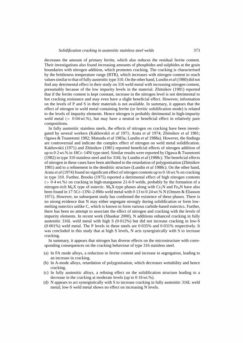
The procedure for calculating BTR from MCL is shown schematically in figure 11. Tocalculate BTR, the cooling curve at the centreline of the weld is obtained by plunging athermocouple behind the arc. The temperature-time variation of the cooling curve can beconverted into a temperature-distance relation using the transformationdistance= speedxtime. This is shown schematically in figure 11, which gives the temperature profile aroundthe weld puddle at the instant of strain application. The crack length is mapped on to thistemperature field as a function of distance from the molten zone. The difference between thetemperatures at either end of the longest crack then gives the brittleness temperature range(BTR). The MCL can thus be used to determine BTR. The starting temperature for BTR isassumed to be at the intersection of molten and solid state cooling curves. The temperatureassociated with a distance corresponding to MCL gives the lower temperature of the BTR.
While the temperature range of cracking is the major component of cracking susceptibility,strain is an essential condition to produce cracking. The BTR can therefore be expressed
Figure 11. Procedure for calculating BTR from theMCL and weld centreline cooling curve (after Lundin& Savage 1965).
376 V Shankar et al
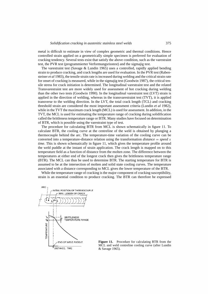
Figure 12. The concept of brittleness temperature range (BTR)during solidification of metals in the strain-temperature regime(after Prokhorov & Prokhorov 1971).
as a region in temperature-strain space, as shown in figure 12. This figure shows that thecracking continues down to a lower temperature as strain is increased and that it saturates at acertain minimum temperature. In many materials a minimum strainεmin is required to initiatecracking called the cracking threshold and also a critical strain rateεcr for cracking to occur,as shown in the figure. Various tests for hot cracking are designed to measure one or more ofthese quantities. In the TVT, the BTR is determined in terms of strain, since the MCL can bederived as a function of strain. In the PVR test, the critical strain rate for cracking is measured.
One advantage of the LVT is that in addition to fusion zone cracking, HAZ cracking canalso be studied in the same specimen, which is not possible using TVT. It is interestingto consider the question of estimating BTR using the LVT. When the varestraint test wasoriginally developed, it was claimed that the BTR could also be determined from this test.However, in the longitudinal varestraint test, the longest cracks are rarely found at the weldcentreline where segregation is highest. In the transvarestraint test (TVT) on the other hand,the weld is strained transverse to the welding direction, which always produces cracking closeto the weld centreline. Hence the TVT is widely preferred for determination of BTR (Arataet al1974). Much work has been done using the Transvarestraint test in Japan, to evaluate thebrittleness temperature range (Arataet al 1977). It is widely believed that TVT is superiorto other methods of testing for fusion zone hot cracking, because this test produces crackingalong the weld centreline in almost all cases. Further, the MCL remains constant with strain,providing a true measure of metallurgical susceptibility. On the other hand in the LVT, MCLcontinues to increase with strain. Arataet al (1974) carried out both types of tests in severalstainless steels and concluded that at high strains(> 2·5 wt.%), the MCL values obtained byeither method are equivalent. More recently, Linet al (1992) have suggested that in the LVT,the actual distance between the isotherms at either end of the crack must be considered ratherthan the maximum crack length, for cracks that are away from the weld centreline. Theyproposed that this measure, termed maximum crack distance or MCD, is more relevant forBTR evaluation. Shankaret al (2000b) comparing results of the two tests showed that MCLfrom the LVT is always higher than that in the TVT. They found that MCD values from theLVT for ten different stainless steels were in direct proportion to the MCL from the TVT. Therelation between MCD and MCL is shown in figure 13, which demonstrates that it is possibleto reliably estimate BTR from the LVT.
5.2 Relation between test criteria and actual cracking behaviour
Although it is possible to assess materials for their relative susceptibility to cracking usingthe TCL and BTR criteria, application of these results to practical welding situations iscomplicated by the fact that in the actual case, strain, strain rate and stress are all variable evenwithin a given geometrical configuration. Tests such as theY-groove test (Miura 1981) or the

Solidification cracking in austenitic stainless steel welds 377
Figure 13. The concept of maximum crackdistance (MCD) in the LVT and its rela-tion to the MCL in transvarestraint test,(a)relation between MCD and MCL for cen-treline cracks and off-centreline cracks and(b) Correlation between MCD in longitu-dinal test and MCL in transvarestraint testat 4% strain.
circular patch test (Lingenfelter 1972) or actual weld joints have been used for correlationwith varestraint test results. Lingenfelter found that the cracking behaviour of two heats ofalloy 800, when welded by GTAW to form butt joints in 12mm thickness, showed crackingas predicted by the varestraint test. Miura (1981) found good correlation between varestrainttest results and cracking in the Y-groove test. He investigated several heats of 304, 316 and347 stainless steels using the varestraint test as well as theY-groove test. The cracked length intheY-groove test specimens increases linearly with TCL in the varestraint test, after an initialthreshold TCL value. Below this threshold TCL, there is no cracking in the Y-groove test.
However, Linet al (1992) found that, when comparing cracking in pipe welds of two fullyaustenitic stainless steels, ranking based on BTR gives more accurate prediction of actualbehaviour than TCL from the varestraint test. Recent work (Shankar 2000) has shown thatweld bead geometry can have a significant effect on TCL. Changes in weld width, for example,can occur due to variations in levels of surface active elements such as S, O and to a lesserextent, N (Mills & Keene 1990). The TCL, when normalised by the weld width, shows goodcorrelation with BTR, as shown in figure 14. Nevertheless, the study showed that the TCLis a complex parameter that depends on several factors apart from segregation leading toobservation of a BTR such as the dendrite arm spacing, macroscopic grain structure, rheologyof fluid flow, among others.
This literature review shows that opinion is divided on the choice of criteria for crackingassessment of materials. Further, there are difficulties in applying the results of variablerestraint tests to actual welding situations. Recent work on hot cracking of low carbon steelduring continuous casting (Wonet al 2000) has shown that it is possible to get reliablepredictions of cracking by taking into account the deformation of the solidifying metal, inaddition to segregation effects. A similar approach in treating weld cracking could lead tobetter predictability of cracking behaviour.
6. Summary and conclusions
A review of solidification cracking in austenitic stainless steel welds shows that the problem ismore prevalent in fully austenitic and stabilized stainless steels. Solidification mode is a majordeterminant of cracking susceptibility; ensuring an FA or F mode ensures the best resistance

378 V Shankar et al
Figure 14. Correlation between TCL inlongitudinal varestraint test and BTR (R2 isthe correlation coefficient and the equationshown is an error-weighted fit).
to cracking. The WRC-92 diagram has been found useful in determining safe compositionalregimes for cracking based on the solidification mode criteria. Cracking is greater in morealloyed stainless steels than in leaner versions. In the latter the amount of retained ferrite islower in the FA/F solidification modes than in the higher-alloyed steels.
A large number of studies have been done on the effect of impurity and alloying elementson cracking behaviour. The review considered in detail the effects of impurity elements Sand P and alloying elements N, Ti and Nb on cracking. In N-enhanced stainless steels (N upto 0·2%), cracking is found to be dependent on the levels of impurity elements. ParticularlyS may have a synergistic detrimental effect when present at high levels in fully austeniticsteels. There is no strong evidence that N may itself form low-melting phases unlike C, whichis known to form various carbide-based eutectics. Ti and Nb increase cracking by formingvarious eutectics in conjunction with S, N and C. The most deleterious phases in such steels areprobably the carbosulphides such as those of titanium, followed by the carbonitrides and thecarbides. In Ti-bearing stainless steels, the amount of these phases increases with increasingstabilization ratio, i.e. (Ti,Nb)/(C,N). A lower ratio is desirable for minimizing the crackingpropensity. In Ti-bearing fully austentic stainless steel Ti/(C+N) between 2 and 3 was foundoptimal.
Present theories on hot cracking suggest that cracking in welds depend on mechanical andmetallurgical factors that are assumed to be independent of one another. However, there iscontroversy regarding at what stage during solidification cracking initiates. Some studies haveshown that cracking could initiate very early during solidification (0·15 fraction solid). Recentwork shows that prediction of cracking is more successful when mechanical behaviour of thesolid is also considered than when only segregation is taken into account.
A review of hot cracking assessment methods and criteria shows that the brittleness tem-perature range or BTR is a useful concept. The BTR is determined from the maximum cracklength in the varestraint test. An alternative way to measure cracking is to use a variable strainrate test to determine the critical strain rate for cracking. The BTR is much less subject toexperimental variation than total crack length or TCL; one way to improve the reliability ofTCL is to normalize crack length by weld width. Although impurity segregation is a majorcontributor to TCL, other factors such as dendrite arm spacing and grain orientations, alsoappear to have a minor role in determining TCL. Application of hot cracking test results toactual welding situations is complicated by the fact that the way strain is applied also influ-ences cracking.
Solidification cracking in austenitic stainless steel welds 379
The authors are grateful to Dr. Baldev Raj for his keen interest and encouragement during thecourse of this work.
References
Arata Y, Matsuda F, Katayama S 1977 Solidification crack susceptibility in weld metals of fullyaustenitic stainless steels (report II) – effect of ferrite, P, S, C, Si, and Mn on ductility properties ofsolidification brittleness.Trans. Jpn. Weld. Res. Inst.6: 105–116
Arata Y, Matsuda F, Saruwatari S 1974 Varestraint test for solidification crack susceptibility in weldmetals of austenitic stainless steels.Trans. Jpn. Weld. Res. Inst.3: 79–88
Babu S S, Vitek J M, Iskander Y S, David S A 1997 New model for prediction of ferrite number ofstainless steel welds.Sci. Technol. Welding Joining2: 279–285
Bhadeshia H K D H, David S A, Vitek J M 1991 Solidification sequences in stainless steel dissimilaralloy welds.Mater. Sci. Technol.7: 50–61
Blake P D 1979 Nitrogen in steel weld metals.Metal Constr.9: 196–197Borland J C 1960 Generalized theory of super-solidus cracking in welds (and castings).Br. Weld. J.
7: 508–512Borland J C,Younger R N 1960 Some aspects of cracking in welded Cr–Ni austenitic steels.Br. Weld.
J. 7: 22–59Brooks J A 1974 Effect of alloy modifications on HAZ cracking of A-286 stainless steel.Weld. J.53:
517s–523sBrooks J A 1975 Weldability of high N, high-Mn austenitic stainless steel.Weld. J.54: 189s–195sBrooks JA, Lambert Jr. F J 1978 The effects of phosphorus, sulfur and ferrite content on weld cracking
of type 309 stainless steel.Weld. J.57: 139s–143sBrooks J A, Thompson A W, Williams J C 1984 A fundamental study of the beneficial effects of
δ-ferrite in reducing weld cracking.Weld. J.63: 71s–83sBrooks J A, Thompson A W 1991 Microstructural development and solidification cracking suscepti-
bility of austenitic stainless steel welds.Int. Mater. Rev.36: 16–44Cieslak M J, Ritter A M, Savage W F 1982 Solidification cracking and analytical electron microscopy
of austenitic stainless steel weld metals.Weld. J.61: 1s–8sClyne T W, Davies G J 1981 The influence of composition on solidification cracking susceptibility in
binary alloy systems.Bri. Foundryman74: 65–73David S A, Goodwin G M, Braski D N 1979 Solidification behaviour of austenitic stainless steel filler
metals.Weld. J.58: 330s–336sDixon B 1988 Weld metal solidification cracking in austenitic stainless steels.Aust. Weld. J.16: 2–10Eckenrod J J, Kovach C W 1979Effect of nitrogen on the sensitization, corrosion and mechanical
properties of 18Cr-8Ni stainless steels(eds) C R Brinkman, H W Garvin,ASTM STP679, pp 17–41Egnell L, May W M 1970 Welding trials on a titanium-bearing austenitic steel.Welding Inst. Conf. on
welding of creep-resistant steels,pp 144–151Folkhard E 1988Welding metallurgy of stainless steels(New York: Springer Verlag)Fredriksson H 1979 Transition from peritectic to eutectic reaction in iron-base alloys.Solidification
and casting of metals(London: The Metals Society) pp 131–138Goodwin G M 1987 Development of a new hot-cracking test – the sigmajig.Weld. J.66: 33s–38sGoodwin G M 1988 The effects of heat input and weld process on hot cracking in stainless steel.Weld.
J. 67: 88s–94sGoodwin G M 1990 Test methods for evaluating hot cracking : review and perspective.Advances in
welding metallurgy(Miami, FL: Am. Welding Soc./Jap. Welding Soc./Japn. Welding Eng. Soc.)pp 37–49
Hammar O, Svensson U 1979 Influence of steel composition on segregation and microstructure duringsolidification of austenitic stainless steels.Solidification and casting of metals(London: The MetalsSociety) pp 401–410

380 V Shankar et al
Hemsworth B, Boniszewski T, Eaton N F 1969 Classification and definition of high temperaturewelding cracks in alloys.Met. Constr. Br. Weld. J.2: 5–16
Hoerl A, Moore T J 1957 The welding of type 347 steels.Weld. J.46: 442s–448sHull F C 1960 Effects of alloying additions on hot cracking of austenitic stainless steels.Proc. ASTM
60: 667–690Hull F C 1967 The effect ofδ-ferrite on the hot cracking of stainless steel.Weld. J.46: 399s–409sJolley G, Geraghty J E 1979 Solidification cracking in 18Cr–13Ni–1Nb stainless steel weld metal: the
role of magnesium additions.Solidification and casting of metals(London: The Metals Society)pp 411–415
Kakhovskii N I et al 1971 Effects of silicon, nitrogen and manganese on chemical heterogeneity intype 0Kh23N28M3D3T weld metals and their resistance to hot cracking.Avtomatich. Svarka8:11–14
Kelly T F, Cohen M, Vandersande J B 1984 Rapid solidification of a droplet-processed stainless steel.Met. Trans.A15: 819–833
Koseki T, Flemings M C 1996 Solidification of undercooled Fe–Cr–Ni alloys part II – microstructuralevolution.Metall. Mater. Trans.A27: 3226–3240
Koseki T, Matsumiya T, Yamada W, Ogawa T 1994 Numerical modeling of solidification and subse-quent transformation of Fe–Cr–Ni alloys.Metall. Mater. Trans.A25: 1309–1321
Kotecki D J, Siewert T A 1992 WRC-1992 constitution diagram for stainless steel weld metals: Amodification of the WRC-1988 diagram.Weld. J.71: 171s–178s
Kujanpaa V, Suutala N, Takalo T, Moisio T 1979 Correlation between solidification cracking andmicrostructure in austenitic–ferritic stainless steel welds.Weld. Res. Int.9: 55–76
Kujanpaa V P 1985 Effects of steel type and impurities in solidification cracking of austeneniticstainless steel welds.Met. Constr.117: 40R–46R
Kurz W, Fischer D J 1985Fundamentals of solidification(New York: Trans. Tech.)Li L, Messler R W 1999 The effects of phosphorus and sulfur on susceptibility to weld hot cracking
in austenitic stainless steels.Weld. J.88: 387-s–396-sLin W, Nelson T, Lippold J C 1992 InProc. ‘Eighth Annual North American Welding Research
Conference’(Columbus, OH: Am. Welding Soc./Edison Welding Inst./TWI) pp 1–6Lingenfelter A C 1972 Varestraint testing of nickel alloys.Weld. J.51: 430s–436s.Lundin C D, DeLong W T, Spond D F 1975 Ferrite-fissuring relationships in austenitic stainless steel
weld metals.Weld. J.54: 241s–246sLundin C D, Chou C-P D, Sullivan D J 1980 Hot cracking resistance of austenitic stainless steel weld
metals.Weld. J.59: 226s–232sLundin C D, Lingenfelter A C, Grotke G E, Lessman G G, Matthews S J 1982 The varestraint test.
Weld. Res. Bull.(280): 1–19Lundin C D, Chou C-P D 1983 Hot cracking of austenitic stainless steels weld metals.WRC Bull.
No. 289Lundin C D, Menon R, Lee C H, OsorioV 1986 New concepts in varestraint testing for hot cracking. In
Welding Research: The State of the Art, JDC University Research Symposium Proceedings, ASM,pp 33–42
Lundin C D, Lee C H, Menon R, Osorio V 1988a Weldability evaluations of modified 316 and 347austenitic stainless steels: Part I – preliminary results.Weld. J.67: 35s–46s
Lundin C D, Lee C H, Menon R 1988b Hot ductility and weldability of free machining austeniticstainless steel.Weld. J.67: 119s–130s
Lundin C D, Lee C H, Qiao C Y P 1988cGroup sponsored study – weldability and hot ductilitybehaviour of nuclear grade austenitic stainless steels. Final Report, Univ. of Tennessee, Knoxville,TN
Massalski T B 1996Alloy phase diagrams(Metals Park, OH: ASM)Masumoto I, Takami K, Kutsuna M 1972 Hot cracking of austenitic stainless steel weld metal.J. Jpn.
Welding Soc.41: 1306–1314

Solidification cracking in austenitic stainless steel welds 381
Matsuda F 1990 Hot crack susceptibility of weld metal. InAdvances in welding metallurgy(Miami,FL: Am. Welding Soc./Jap. Welding Soc./Japn. Welding Eng. Soc.) pp 19–35
Matsuda F, Nakagawa H, Nakara K, Sasaki I 1976Trans. Jpn. Weld. Res. Inst.5: 53–67Matsuda F, Nakagawa H, Uehara T, Katayama S, ArataY 1979 A new explanation for role ofδ-ferrite
improving weld solidification crack susceptibility in austenitic stainless steel.Trans. Jpn. Weld.Res. Inst.8: 105–112
Matsuda F, Katayama S, Arata Y 1981 Solidification crack susceptibility in weld metals of fullyaustenitic stainless steels – solidification crack susceptibility and amount of phosphide and sulphidein SUS 310 weld metal.Trans. Jpn. Weld. Res. Inst.10: 201–212
Matsuda F, Nakagawa H, Katayama S,ArataY 1982a Solidification crack susceptibility in weld metalsof fully austenitic stainless steels (report VI) – effect of La or REM addition on solidification crackresistance.Trans. Jpn. Weld. Res. Inst.11: 79–94
Matsuda F, Nakagawa H, Sorada K 1982b Dynamic observation of solidification and solidificationcracking during welding with optical microscope.Trans. Jpn. Weld. Res. Inst.11: 67–77
Matsuda F, Nakagawa H, Katayama S,ArataY 1983a Solidification crack susceptibility in weld metalsof fully austenitic stainless steels (report VIII) – effect of nitrogen on cracking in SUS 304 weldmetal.Trans. Jpn. Weld. Res. Inst.12: 89–95
Matsuda F, Katayama S, Arata Y 1983b Solidification crack susceptibility in weld metals of fullyaustenitic stainless steels (report IX) – effect of titanium on solidification crack resistance.Trans.Jpn. Weld. Res. Inst.12: 87–92
Matsuda F, Nakagawa H, Kato I, Murata Y 1986Trans. Jpn. Weld. Res. Inst.15: 99–112Matsuda F, Nakagawa H, Lee J B 1989a Weld cracking in duplex stainless steel (Report II) – modelling
of cellular dendritic growth during weld solidification.Trans. Jpn. Weld. Res. Inst.18: 107–117Matsuda F, Nakagawa H, Lee J B 1989bWeld cracking in duplex stainless steel (Report III) – numerical
analysis of solidification BTR in stainless steel.Trans. Jpn. Weld. Res. Inst.18: 119–126Maziasz P J 1989 Developing an austenitic stainless steel for improved performance in advanced fossil
power facilities.J. Met.12: 14–20Medovar I 1954 On the nature of weld hot cracking.Avtomatich. Svarka7: 12–28Menon R, Kotecki D J 1989 Literature review – nitrogen in stainless steel weld metal.WRC Bull.
No. 389, pp 142–161Mills K C, Keene B J 1990Int. Mater. Rev.35: 185–216Miura M 1981 Weldability of austenitic stainless steel tubes.J. Sumitomo Met.34: 201–213Mudali U K, Dayal R K, Gill T P S, Gnanamoorthy J B 1986 Influence of nitrogen addition on
microstructure and pitting corrosion resistance of austenitic weld metals.Werkstoffe Korros.37:637–643
Ogawa T, Tsunetomi E 1982 Hot cracking susceptibility of austenitic stainless steels.Weld. J.61:82s–93s
Ogawa T, Suzuki K, Zaizen T 1984 The weldability of nitrogen-containing austenitic stainless steel:part II – porosity, cracking and creep properties.Weld. J.63: 213s–223s
Olson D L 1985 Prediction of austenitic weld metal microstructure and properties.Weld. J.64: 281s–295s
Omsen A, Eliasson L 1971 Distribution of nitrogen during solidification of a 17·5Cr–13Ni–2·8Mostainless steel.J. Iron Steel Inst.10: 830–833
Pehlke R D, Elliott J F 1960Trans. AIME218: 1088–1101Pellini W S 1952 Strain theory of hot tearing.FoundryNovember 1952, p 125Pepe J J, Savage W F 1967 Effects of constitutional liquation on 18-Ni maraging steel weldments.
Weld. J.46: 411s–422sPersson N G 1971 The influence of sulphur on the structure and weldability of a titanium-bearing
austenitic stainless steel.Proc. of the Soviet-Swedish Symposium. Clean Steel, Sandviken, SwedenI: 142–151
Prokhorov N N, Prokhorov N Nikol 1971 Fundamentals of the theory for technological strength ofmetals while crystallizing during welding.Trans Jap. Welding Soc.2: 109–117

382 V Shankar et al
Rabensteiner G, Tosch J, Schaberiter H 1983 Hot cracking problems in different fully austenitic weldmetals.Weld. J.62: 21s–27s
Savage W F, Lundin C D 1965 Application of the varestraint technique to the study of weldability.Weld. J.45: 497s–503s
Schaeffler A L 1949 Constitution diagram for stainless steel weld metal.Met. Progr.56: 680–680BScherer R, Riedrich G, Hougardy H 1941 US Patent 2 240 672Semenyuk N I, Rabkin D M, Korshun A O 1986 Determining the hot cracking temperature range in
the welding of aluminium alloys.Autom. Weld.39: 16–18Shankar V 2000Role of compositional factors in hot cracking of austenitic stainless steel weldments.
PhD thesis, Indian Institute of Technology – Madras, ChennaiShankarV, Gill T P S, TerranceA L E, Mannan S L, Sundaresan S 2000a Relation between microstruc-
ture, composition and hot cracking in Ti-stabilised austenitic stainless steel weldments.Metall.Mater. Trans.A31: 3109–3122
Shankar V, Gill T P S, Mannan S L, Sundaresan S 2000b Criteria for hot cracking evaluation inaustenitic stainless steel welds using the longitudinal varestraint and transvarestraint tests.Sci.Technol. Weld. Join.5: 91–97
Siewert T A, McCowan C N, Olson D L 1988 Ferrite number prediction to 100 FN in stainless steelweld metal.Weld. J.37: 289s–298s
Smith C S 1948 Grains, phases and interfaces: an interpretation of microstructure.Trans. Am. Inst.Mining Metall. Eng.175: 15–51
Stevens S M 1989 Forms of nitrogen in weld metal.WRC Bull.(369): pp 1–2Suutala N, Moisio T 1979Solidification technology in the foundry and the casthouse(London: The
Metals Society)Suutala N 1982 Effect of manganese and nitrogen on the solidification mode in austenitic stainless
steel welds.Met. Trans.A13: 2121–2130Suutala N 1983 Effect of solidification conditions on the solidification mode in austenitic stainless
steels.Met. Trans.A14: 191–197Thier H, Killing R, Killing U 1987 Solidification modes of weldments in corrosion resistant steels –
how to make them visible.Met. Constr.19: 127–130Vitek J M, Iskander Y S, Oblow E M 2000 Improved ferrite number prediction in stainless steel arc
welds using artificial neural networks – Parts I and II.Weld. J.79: 33-s–40-s, 41-s–50-sWonY M,Yeo T-J, Seol D J, Oh K H 2000A new criterion for internal crack formation in continuously
cast steels.Met. Mater. Trans.B31: 779–794Wolstenholme D A 1973 Weld crater cracking in Incoloy 800.Weld. Met. Fabrication41: 433–438Zhitnikov N P 1981 The hot cracking resistance of austenitic CrNi weld metal and weld zone in
relation to nitrogen content.Weld. Prod.3: 14–16