Embed Size (px)
Citation preview

Solid State Telescope InstrumentpEnd of Prime Mission Review
Dr Davin LarsonDr. Davin LarsonUC Berkeley SSL
THEMIS SWG SST-1 UCB, December, 19 2009
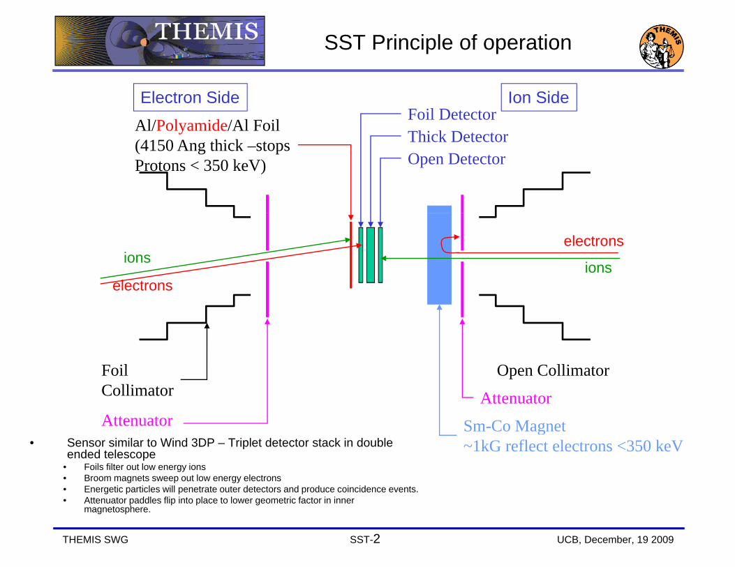
SST Principle of operation
Thick DetectorAl/Polyamide/Al Foil(4150 A thi k t
Foil DetectorElectron Side Ion Side
Thick Detector(4150 Ang thick –stopsProtons < 350 keV) Open Detector
electrons
ionselectrons
ionselectrons
FoilCollimator
Sm Co Magnet
AttenuatorAttenuator
Open Collimator
• Sensor similar to Wind 3DP – Triplet detector stack in double ended telescope
• Foils filter out low energy ions• Broom magnets sweep out low energy electrons• Energetic particles will penetrate outer detectors and produce coincidence events.
f f
Sm-Co Magnet~1kG reflect electrons <350 keV
Attenuator
THEMIS SWG SST-2 UCB, December, 19 2009
• Attenuator paddles flip into place to lower geometric factor in inner magnetosphere.

Summary Performance
SST Prime mission requirements• No major failures during prime mission
Degradation of 3 out of 20 ion detectors was much greater than• Degradation of 3 out of 20 ion detectors was much greater than expected (possibly due to radiation damage but cause not known for certain)All data is valid for timing analysis• All data is valid for timing analysis
• SST met nearly all mission and science requirements• SST met most performance requirements• SST team has provided software and preliminary calibrated data • Over ? papers with SST data published
SST Current Status• All sensors continue functioning • All attenuator mechanisms are working well• Final calibrations are still in progress• No noticeable increase in background noise since launch
THEMIS SWG SST-3 UCB, December, 19 2009
No noticeable increase in background noise since launch

SST
ESAElectrons
SST
ect o s
ESAIons
THEMIS SWG SST-4 UCB, December, 19 2009
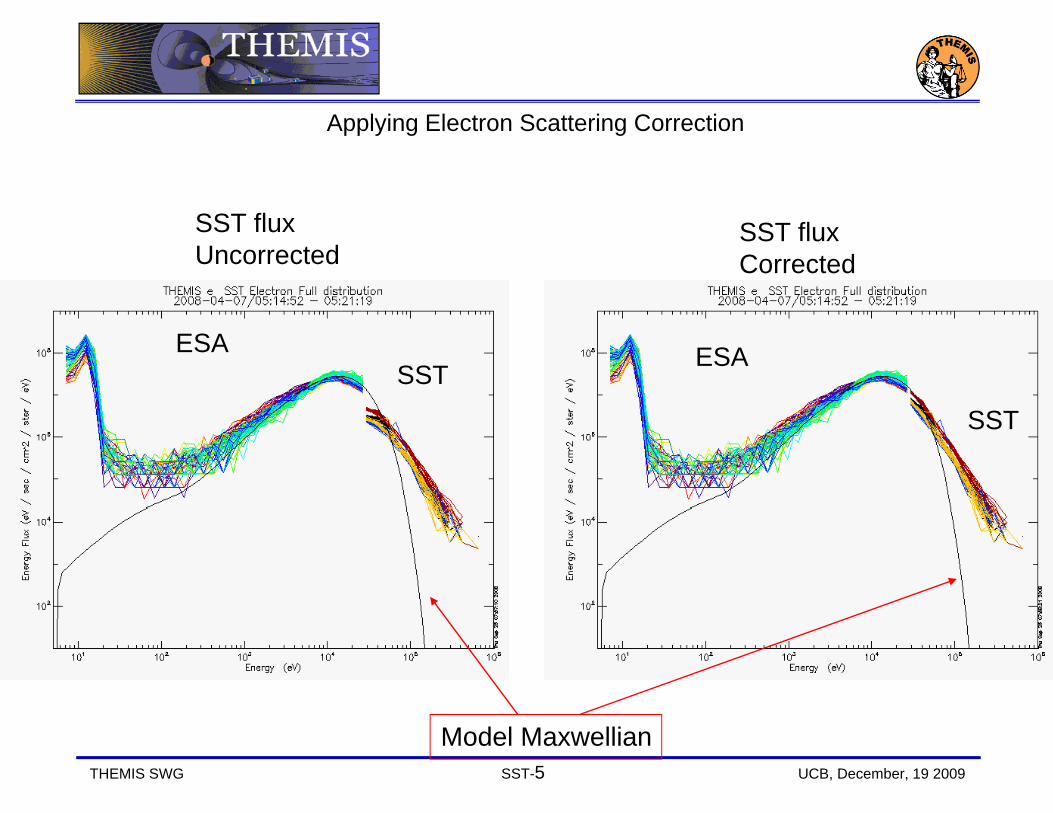
Applying Electron Scattering Correction
SST fluxUncorrected
SST fluxCorrected
ESA ESASST
SST
THEMIS SWG SST-5 UCB, December, 19 2009
Model Maxwellian

Electon Efficiency correction for E>300 keV
U t d Accounting for high energyUncorrected g g gyefficiency.
We know there is a substantial difference in measured flux as compared with LANL! (~8)
THEMIS SWG SST-6 UCB, December, 19 2009
Slightly higher flux at high energyflux as compared with LANL! (~8)

Dead Layer (thickness grows in time)
Solid state detectors only measure the grows in time)
ChargedParticle
only measure the energy deposited in the active (depleted) region of the silicon Particle
trackAs the dead layer grows in time all energy channels shift to higher
Ionization charges onlyCollected fromDepleted region
channels shift to higher energy
During the first 9 months f l h i d
Electric
Depleted regionafter launch we noticed a gradual reduction in signal, primarily in 3 of 20 ion detectors (1 on Probe
fieldion detectors (1 on Probe-B, 2 on Probe-C) Somewhat mitigated by increasing bias voltage
THEMIS SWG SST-7 UCB, December, 19 2009Distance
increasing bias voltage

Correcting for increase in Dead layer
Themis E is shownThemis B&C have much more severe damage
Ion Distribution
Uncorrected
Ion Distribution
Corrected
Themis B&C have much more severe damage
U co ected
All energiesShifted up
THEMIS SWG SST-8 UCB, December, 19 2009
Shifted up6 keV

Future Improvements
SST Data Work in Progress or planned workp• In flight calibration of ion
sensors• Placing new electronPlacing new electron
calibrations in public source• Modeling of SST sensor head
using GEANT4using GEANT4• Removal of cross contamination
between electron and ion channels in innerchannels in inner Magnetosphere
• Improved dead time correctionsNew software algorithms for• New software algorithms for more accurate moments (combining ESA and SST partial moments)
THEMIS SWG SST-9 UCB, December, 19 2009
moments)

Summary Performance
SST Prime mission requirements• No major failures during prime mission
Degradation of 3 out of 20 ion detectors was much greater than• Degradation of 3 out of 20 ion detectors was much greater than expected (possibly due to radiation damage but cause not known for certain)All data is valid for timing analysis• All data is valid for timing analysis
• SST met nearly all mission and science requirements• SST met most performance requirements• SST team has provided software and preliminary calibrated data • Over ? papers with SST data published
SST Current Status• All sensors continue functioning • All attenuator mechanisms are working well• Final calibrations are still in progress• No noticeable increase in background noise since launch
THEMIS SWG SST-10 UCB, December, 19 2009
No noticeable increase in background noise since launch

End of Presentation
THEMIS SWG SST-11 UCB, December, 19 2009

SST efforts to facilitate data analysis
• SST data is available within 24 hrs after collection on the THEMIS Website:
• Summary Plots with SST data at: http://themis.ssl.berkeley.edu/summary.shtml?autoload=1
• SST instrument paper (in preparation) :
• Instrument description at: http://themis.ssl.berkeley.edu/instrument_sst.shtml
THEMIS SWG SST-12 UCB, December, 19 2009

Bremsstrahlung Background
Energetic electrons measured by the SST detectors produce X-detectors produce Xrays that contaminate the ion ESA measurement
Electrons
measurement.
Moment calculations without removal of thiswithout removal of this background will overestimate ion d it ( ) Si l
Ions
density (green). Simple background removal algorithms (black) h l b ill dhelp, but still do not provide good agreement with
THEMIS SWG SST-13 UCB, December, 19 2009
electron density (red).

Caveats when using SST data
Saturation at high count rates (>20 kHz/channel)Sun Pulse
• Once per spinOnce per spin • Affects all channels• Easily removed if FULL dists are used
Low energy electron geometric factor caused by scattering by foil
Ion detectors – Increasing Dead layer vs time.Cross Species contamination
• Only important when flux of >400 keV particles becomes significant (inner magnetosphere)
Attenuator state (64x) • Closed within inner magnetosphere (<10 Re)• Controlled by count rate in outer MS• Controlled by count rate in outer MS
We know there is a substantial difference in measured flux as compared with LANL! (~10)
THEMIS SWG SST-14 UCB, December, 19 2009

Publication History and Data Maturity
THEMIS Papers utilizing SST Data: • List in formulation (Vassilis has this).
Data Analysis Software and ProductsData Analysis Software and Products• SST raw and level 2 data available within ~24 hrs of collection. • Data analysis tools available to all, regular improvements to software.
El t L l 2 d t ill b t d t t f f il• Electron Level 2 data will be soon regenerated to account for foil efficiency.
• Ion Level 2 data will be regenerated to account for degradation of ion sensors.
• Data will continue to improve with age like a good bottle of wine.
THEMIS SWG SST-15 UCB, December, 19 2009

SST Lessons Learned• TEST – TEST – TEST! And then test some more. Consider all possible failure modes.• Set up GSE that will record all instrument data as well as laboratory environmental data (i.e. vacuum
pressure, temperature, input voltages and currents) so that if a problem occurs the experimenter can go back and find the cause.
• Automate test routines so that they can be repeated identically and quickly. Avoid human input.• Be more selective when choosing detectors. Monitor many detectors over a long time interval (months)
and then pick the best ones that show no change over time.• Leave equipment running (and recording) throughout thermal-vac testing. Perform tests at all
temperatures, not just the extremes. Ignore any concerns about instruments running while not “monitored” by a human.
• Conducting (aluminum) tape does not work well in vacuum.• Don’t do initial instrument turn-on while in the radiation belts. (or if you do – at least know that the
instrument is in the radiation belt)• Check (and test) polarity of all polarized capacitors on all boards. Don’t assume the circuit board was
printed correctly. (This is a very common problem!)• Thoroughly test instrument for light sensitivity.• Test for noise contamination early.• Measure and/or account for in-rush current at instrument turn-on.• Watch out for large preamp current draw during saturation events.• Build at least two of every unit, even if you only need one unit.• Built in test electronics simplifies in-flight instrument monitoring.• Two electron sensors looking in opposite directions are essential for accurate Ve measurements
when density fluctuations are present.• Combined plasma measurements (ESA+SST) are required for correct plasma moment calculations.
THEMIS SWG SST-16 UCB, December, 19 2009

Requirements and Specifications
MeasurementTh SST i t t 3 D l t d i di t ib ti f ti• The SST instrument measures 3-D electron and ion energy distribution functions over
the Energy range 30 KeV to ~1 MeV. • A full 4-pi distribution measurement is produced during each spin• Raw measurements are compressed to selectable “reduced distributions” and momentsp
Implementation• 2 Pairs of double ended Triplet Stack of electrostatic analyzers have 180 degree field of2 Pairs of double ended Triplet Stack of electrostatic analyzers have 180 degree field of view• Field of view is divided into 16 phi sectors and 4 elevation bins• SST detectors have configurable energy, angle and time resolution. These functions are
b dset by command.• Higher level data formatting and computed products are carried out in the ETC board.• Default Energy table is approximately logarithmic.
SST Instrument continues to operate and continues to produce data products. However there is some degradation of ion detectors. The ion sensor degradation primarily affects 2 probes (P1 and P2).
THEMIS SWG SST-17 UCB, December, 19 2009
sensor degradation primarily affects 2 probes (P1 and P2).

Block Diagram
• Electronics functional design is similar to Stereo STE• Amptek 225FB used as preamplifier in sensor head.• PHA circuitry on DAP board in the IDPU
Signal chain: 1 of 12 channels shownBias Voltage
DAC
Test Pulserg
FPGAC i id
DACThresh
GainPD
ADC
CoincidenceLogic &
AccumulatorsA225FPreampShaper
MemoryBLRShaper
DFE
THEMIS SWG SST-18 UCB, December, 19 2009
DFEBoard
DAP Board

Mission Requirements
REQUIREMENT SST DESIGNIN-1. The Instrument Payload shall be designed for at least a two-year lifetime
Compliance. All 10 Sensors functioning after 2.5 years. y y
IN-2. The Instrument Payload shall be designed for a total dose environment of 33 krad/year(66 krad for 2 year mission, 5mm of Al, RDM 2)
Compliance. No evidence of radiation degradation of the electronics. Some degradation of detectors possibly due to low energy (30-100 keV) ion implantations .
IN-3. The Instrument Payload shall be Single Event Effect (SEE) tolerant and immune to destructive latch-up
Compliance. No known SEEs or latch-ups of the SST sensors or electronics.
IN-7 No component of the Instrument Payload shall Compliance No mass budget problemIN-7. No component of the Instrument Payload shall exceed the allocated mass budget in THM-SYS-008 THEMIS System Mass Budget.xls
Compliance. No mass budget problem.Sensor: 554 gm x2 (Measured)Harness: 141 gm x2 (1.73 meter)(DAP Board tracked with IDPU)
IN-9. No component of the Instrument Payload shall exceed the power allocated in THM-SYS-009 THEMIS System Power Budget.xls
Compliance. No power problems during 2.5 years.DFE + DAP: 1200 mW (Estimate @ 10 kHz count rate)
IN-13. The Instrument Payload shall survive the Compliance. No observed anomalies during temperature ranges provided in the ICDs eclipse.
IN-14. The Instrument Payload shall perform as designed within the temperature ranges provided in
Compliance. No SST temperature problems.
THEMIS SWG SST-19 UCB, December, 19 2009
the ICDs

Mission Requirements
REQUIREMENT SST DESIGNIN-16 The Instrument Payload shall comply with the Magnetics Cleanliness standard described in the
Compliance. SST complied (with expanded budget) and experienced no magnetic problems. <2 nT @Magnetics Cleanliness standard described in the
THEMIS Magnetics Control Planand experienced no magnetic problems. 2 nT @ 2.5 meters. 11 Hz FGM noise first attributed to SST was found to be due to aliasing of digital noise in the IDPU
IN-17 The Instrument Payload shall comply with the Compliance. SST complied and experienced no y p yTHEMIS Electrostatic Cleanliness Plan
p p pelectrostatic cleanliness problems.
IN-18 The Instrument Payload shall comply with the THEMIS Contamination Control Plan
Compliance. SST complied and experienced no contamination problems.
IN-19 All Instruments shall comply with all electrical Compliance SST complied and experienced noIN 19. All Instruments shall comply with all electrical specifications
Compliance. SST complied and experienced no electrical problems.
IN-20. The Instrument Payload shall be compatible per IDPU-Instrument ICDs
Compliance. SST was compatible and experienced no communication problems with the IDPU and ETC. ETC table loading problems were resolved duringETC table loading problems were resolved during commissioning phase prior to first tail season.
IN-21. The Instrument Payload shall be compatible per the IDPU-Probe Bus ICD
Compliance. SST was compatible.
IN 23 The Instrument Payload shall verify Compliance SST performance met the VerificationIN-23 The Instrument Payload shall verify performance requirements are met per the THEMIS Verification Plan and Environmental Test Spec.
Compliance. SST performance met the Verification Plan and Environmental Test Specification.
IN-24 The Instrument Payload shall survive and function prior during and after exposure to the
Compliance. SST survived all pre-launch testing and continues to function
THEMIS SWG SST-20 UCB, December, 19 2009
function prior, during and after exposure to the environments described in the THEMIS Verification Plan and Environmental Test Specification
and continues to function.

Science RequirementsREQUIREMENT SST DESIGN
IN.SST-1. The SST shall perform measurements of the tailward-moving current disruption boundary speed using the finite gyroradius technique
Compliance. Provided by Full Distribution Functions (FDFs). Technique used in paper by (provide reference)using the finite gyroradius technique reference)
IN.SST-2. The SST shall measure the time-of-arrival of superthermal ions and electrons of different energies emanating from the reconnection region to determine
Compliance. 3 second time resolution of FDFs
emanating from the reconnection region to determine RX onset time.
IN.SST-3. The SST shall obtain partial moments of the plasma electron and ion distributions in the magnetotail plasma sheet
Compliance. Partial moments produced by ETC board but are of limited quality for ions. Higher quality partial moments are computed on the groundplasma sheet moments are computed on the ground.
IN.SST-4. The SST shall obtain measurements of ion and electron distribution functions with one spin resolution (<10sec required)
Compliance. Full electron distribution functions at 1 spin resolution obtained in burst mode. Full ion distribution function at 1 spin res are produced in fastresolution ( 10sec required) distribution function at 1 spin res are produced in fast survey .
IN.SST-5. The SST shall measure energetic electron fluxes as close to Earth as 6RE geocentric, at all local times.
Compliance. Attenuator lowers flux sufficiently to avoid saturation at this distance. All Attenuators are functioning nominally after 2.5 yearsg y y
IN.SST-6. The SST shall measure energetic ions in the solar wind, at the magnetopause and in the magnetosheath.
Compliance. As above when sensors are operating
THEMIS SWG SST-21 UCB, December, 19 2009
g

Science RequirementsREQUIREMENT SST DESIGNIN.SST-7. The SST shall measure energetic particles over an energy range of 30-300keV for ions and 30-100keV for electrons found in the magnetotail plasma
Compliance.Electrons: ~30 keV to ~800 keV
100keV for electrons found in the magnetotail plasma sheet . Ions: ~30 keV to ~6 MeV
IN.SST-8. The SST energy sampling resolution, dE/E, shall be better than 30% for ions and electrons.
Compliance.Intrinsic energy resolution is ~6 keV with 1.5 keV bi i M d f ll t l ti i 8 k V @ 30binning. Measured full system resolution is 8 keV @ 30 keV
IN.SST-9. The SST shall be capable of measuring differential energy flux in the range from: 10^2 to 5x10^6 f i 10^3 10^7 f l t (k V/ 2 t k V)
Compliance. Max counting rate estimated at 50,000 cps (per detector). Two geometric factors:
for ions; 10^3-10^7 for electrons (keV/cm2-s -st- keV) whilst providing adequate counts within a 10 second interval.
G1 ~ 0.1 cm2-sterG2 = G1/64.Dead time correction required for R>20,000 cps
IN.SST-10. The SST shall measure over 90 deg. in Compliance.gelevation with a minimum resolution of 45 deg.
pElevation: +/- 60 deg, Resolution:~37 deg.
IN.SST-11. The SST shall have an azimuthal resolution of 45 deg.
Compliance.Azimuthal resolution = 22.5 deg
IN SST 12 Th SST h ll l th hi h ti l C liIN.SST-12. The SST shall supply the high energy partial moments at one spin time resolution.
Compliance.Performed by ETC board
IN.SST-13. SST calibration shall ensure <20% relative flux uncertainty over the ranges defined above.
Partial Compliance. Measured pre-flight;In-flight calibration has shown changes in ion calibration,
THEMIS SWG SST-22 UCB, December, 19 2009
primarily caused by increased dead layers over time.

Scientific assessment of data products: • a. Are the products sufficient to meet L1 requirements?YYes• b. How far do products go beyond L1 science requirements Data maturity: • a. Version history and release dates Level 1 has no version number (unless major architecture
change is required)Level 2(we don't have versions but > you can talk about how
often we re-processed) • b. Data accessibility, calibration and error estimates • c. Community use and publication history [L1 versus non-
L1] > > I will have presented the data analysis tools and concept of data > distribution. > I can find the community use and publication history and will add a chart > > for theuse and publication history and will add a chart > > for the ESA/SST, either in your presentation or in a top-level > presentation.
THEMIS SWG SST-23 UCB, December, 19 2009

ESA and SST combined
Accurate density measurementsmeasurements
Errors in electronErrors in electron velocity measurements due to density fluctuations
THEMIS SWG SST-24 UCB, December, 19 2009

eSST Determines iESA Bgnd
We estimate background using b h h SST d
Background
both the eSST and iESA data.
ElectronsCross fitting these two estimates allows corrections due to
Electrons
corrections due to changes in response with time. Ions
Using eSST rather than iESA estimate Density after background subtractioneliminates removal of real counts at low energy
THEMIS SWG SST-25 UCB, December, 19 2009
energy.